KR100954333B1 - Method and device for measuring response speed of liquid crystal and method and device for driving liquid crystal display device using same - Google Patents
Method and device for measuring response speed of liquid crystal and method and device for driving liquid crystal display device using sameDownload PDFInfo
- Publication number
- KR100954333B1 KR100954333B1KR1020030043805AKR20030043805AKR100954333B1KR 100954333 B1KR100954333 B1KR 100954333B1KR 1020030043805 AKR1020030043805 AKR 1020030043805AKR 20030043805 AKR20030043805 AKR 20030043805AKR 100954333 B1KR100954333 B1KR 100954333B1
- Authority
- KR
- South Korea
- Prior art keywords
- liquid crystal
- level
- temperature
- crystal display
- signal
- Prior art date
- Legal status (The legal status is an assumption and is not a legal conclusion. Google has not performed a legal analysis and makes no representation as to the accuracy of the status listed.)
- Expired - Fee Related
Links
Images


Classifications
- G—PHYSICS
- G09—EDUCATION; CRYPTOGRAPHY; DISPLAY; ADVERTISING; SEALS
- G09G—ARRANGEMENTS OR CIRCUITS FOR CONTROL OF INDICATING DEVICES USING STATIC MEANS TO PRESENT VARIABLE INFORMATION
- G09G3/00—Control arrangements or circuits, of interest only in connection with visual indicators other than cathode-ray tubes
- G09G3/20—Control arrangements or circuits, of interest only in connection with visual indicators other than cathode-ray tubes for presentation of an assembly of a number of characters, e.g. a page, by composing the assembly by combination of individual elements arranged in a matrix no fixed position being assigned to or needed to be assigned to the individual characters or partial characters
- G09G3/34—Control arrangements or circuits, of interest only in connection with visual indicators other than cathode-ray tubes for presentation of an assembly of a number of characters, e.g. a page, by composing the assembly by combination of individual elements arranged in a matrix no fixed position being assigned to or needed to be assigned to the individual characters or partial characters by control of light from an independent source
- G09G3/36—Control arrangements or circuits, of interest only in connection with visual indicators other than cathode-ray tubes for presentation of an assembly of a number of characters, e.g. a page, by composing the assembly by combination of individual elements arranged in a matrix no fixed position being assigned to or needed to be assigned to the individual characters or partial characters by control of light from an independent source using liquid crystals
- G09G3/3611—Control of matrices with row and column drivers
- G—PHYSICS
- G09—EDUCATION; CRYPTOGRAPHY; DISPLAY; ADVERTISING; SEALS
- G09G—ARRANGEMENTS OR CIRCUITS FOR CONTROL OF INDICATING DEVICES USING STATIC MEANS TO PRESENT VARIABLE INFORMATION
- G09G3/00—Control arrangements or circuits, of interest only in connection with visual indicators other than cathode-ray tubes
- G09G3/006—Electronic inspection or testing of displays and display drivers, e.g. of LED or LCD displays
- G—PHYSICS
- G09—EDUCATION; CRYPTOGRAPHY; DISPLAY; ADVERTISING; SEALS
- G09G—ARRANGEMENTS OR CIRCUITS FOR CONTROL OF INDICATING DEVICES USING STATIC MEANS TO PRESENT VARIABLE INFORMATION
- G09G2320/00—Control of display operating conditions
- G09G2320/02—Improving the quality of display appearance
- G09G2320/0252—Improving the response speed
- G—PHYSICS
- G09—EDUCATION; CRYPTOGRAPHY; DISPLAY; ADVERTISING; SEALS
- G09G—ARRANGEMENTS OR CIRCUITS FOR CONTROL OF INDICATING DEVICES USING STATIC MEANS TO PRESENT VARIABLE INFORMATION
- G09G2320/00—Control of display operating conditions
- G09G2320/04—Maintaining the quality of display appearance
- G09G2320/041—Temperature compensation
- G—PHYSICS
- G09—EDUCATION; CRYPTOGRAPHY; DISPLAY; ADVERTISING; SEALS
- G09G—ARRANGEMENTS OR CIRCUITS FOR CONTROL OF INDICATING DEVICES USING STATIC MEANS TO PRESENT VARIABLE INFORMATION
- G09G2320/00—Control of display operating conditions
- G09G2320/06—Adjustment of display parameters
- G09G2320/0693—Calibration of display systems
- G—PHYSICS
- G09—EDUCATION; CRYPTOGRAPHY; DISPLAY; ADVERTISING; SEALS
- G09G—ARRANGEMENTS OR CIRCUITS FOR CONTROL OF INDICATING DEVICES USING STATIC MEANS TO PRESENT VARIABLE INFORMATION
- G09G2340/00—Aspects of display data processing
- G09G2340/16—Determination of a pixel data signal depending on the signal applied in the previous frame
- G—PHYSICS
- G09—EDUCATION; CRYPTOGRAPHY; DISPLAY; ADVERTISING; SEALS
- G09G—ARRANGEMENTS OR CIRCUITS FOR CONTROL OF INDICATING DEVICES USING STATIC MEANS TO PRESENT VARIABLE INFORMATION
- G09G3/00—Control arrangements or circuits, of interest only in connection with visual indicators other than cathode-ray tubes
- G09G3/20—Control arrangements or circuits, of interest only in connection with visual indicators other than cathode-ray tubes for presentation of an assembly of a number of characters, e.g. a page, by composing the assembly by combination of individual elements arranged in a matrix no fixed position being assigned to or needed to be assigned to the individual characters or partial characters
- G09G3/2007—Display of intermediate tones
- G09G3/2011—Display of intermediate tones by amplitude modulation
- G—PHYSICS
- G09—EDUCATION; CRYPTOGRAPHY; DISPLAY; ADVERTISING; SEALS
- G09G—ARRANGEMENTS OR CIRCUITS FOR CONTROL OF INDICATING DEVICES USING STATIC MEANS TO PRESENT VARIABLE INFORMATION
- G09G3/00—Control arrangements or circuits, of interest only in connection with visual indicators other than cathode-ray tubes
- G09G3/20—Control arrangements or circuits, of interest only in connection with visual indicators other than cathode-ray tubes for presentation of an assembly of a number of characters, e.g. a page, by composing the assembly by combination of individual elements arranged in a matrix no fixed position being assigned to or needed to be assigned to the individual characters or partial characters
- G09G3/34—Control arrangements or circuits, of interest only in connection with visual indicators other than cathode-ray tubes for presentation of an assembly of a number of characters, e.g. a page, by composing the assembly by combination of individual elements arranged in a matrix no fixed position being assigned to or needed to be assigned to the individual characters or partial characters by control of light from an independent source
- G09G3/36—Control arrangements or circuits, of interest only in connection with visual indicators other than cathode-ray tubes for presentation of an assembly of a number of characters, e.g. a page, by composing the assembly by combination of individual elements arranged in a matrix no fixed position being assigned to or needed to be assigned to the individual characters or partial characters by control of light from an independent source using liquid crystals
- G09G3/3611—Control of matrices with row and column drivers
- G09G3/3648—Control of matrices with row and column drivers using an active matrix
Landscapes
- Engineering & Computer Science (AREA)
- Physics & Mathematics (AREA)
- Computer Hardware Design (AREA)
- General Physics & Mathematics (AREA)
- Theoretical Computer Science (AREA)
- Chemical & Material Sciences (AREA)
- Crystallography & Structural Chemistry (AREA)
- Liquid Crystal (AREA)
- Liquid Crystal Display Device Control (AREA)
- Control Of Indicators Other Than Cathode Ray Tubes (AREA)
Abstract
Translated fromKoreanDescription
Translated fromKorean도 1은 통상의 액정표시장치에 있어서 데이터에 따른 휘도 변화를 나타내는 파형도이다.1 is a waveform diagram showing a change in luminance according to data in a conventional liquid crystal display.
도 2는 종래의 고속 구동방법에 있어서 데이터 변조에 따른 휘도 변화의 일례를 나타내는 파형도이다.2 is a waveform diagram showing an example of a luminance change caused by data modulation in the conventional high speed driving method.
도 3은 8 비트 데이터에서 종래의 고속 구동방법의 일례를 나타내는 도면이다.3 is a diagram illustrating an example of a conventional high speed driving method in 8 bit data.
도 4는 종래의 고속 구동장치를 나타내는 블록도이다.4 is a block diagram showing a conventional high speed drive device.
도 5는 본 발명의 실시예에 따른 응답속도 측정장치를 나타내는 도면이다.5 is a view showing a response speed measuring apparatus according to an embodiment of the present invention.
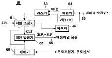
도 6은 도 5에 도시된 시스템을 상세히 나타내는 블록도이다.6 is a block diagram illustrating in detail the system illustrated in FIG. 5.
도 7a 및 도 7b는 본 발명에 따른 응답속도 측정장치에서 이용되는 3 레벨 신호를 나타내는 파형도이다.7A and 7B are waveform diagrams showing three-level signals used in the response speed measuring apparatus according to the present invention.
도 8은 본 발명의 실시예에 따른 응답속도 측정방법을 단계적으로 나타내는 흐름도이다.8 is a flowchart illustrating a method for measuring a response speed in accordance with an embodiment of the present invention.
도 9a 및 도 9b는 3 레벨 신호와 그에 따른 액정의 응답특성을 나타내는 파형도이다.9A and 9B are waveform diagrams illustrating response characteristics of a three-level signal and liquid crystal accordingly.
도 10a는 정극성의 변조 데이터 전압 설정시 최적 응답특성과 임계값의 관계를 나타내는 파형도이다.FIG. 10A is a waveform diagram illustrating a relationship between an optimum response characteristic and a threshold value when setting a positive modulation data voltage. FIG.
도 10b는 부극성의 변조 데이터 전압 설정시 최적 응답특성과 임계값의 관계를 나타내는 파형도이다.FIG. 10B is a waveform diagram illustrating a relationship between an optimum response characteristic and a threshold value when setting a negative modulation data voltage. FIG.
도 11은 본 발명의 실시예에 따른 액정표시소자의 구동장치를 나타내는 블록도이다.11 is a block diagram illustrating a driving device of a liquid crystal display device according to an exemplary embodiment of the present invention.
도 12는 도 11에 도시된 온도별 데이터 변조기의 제1 실시예를 나타내는 블록도이다.FIG. 12 is a block diagram illustrating a first embodiment of a temperature-specific data modulator shown in FIG. 11.
도 13은 도 11에 도시된 온도별 데이터 변조기의 제1 실시예를 나타내는 블록도이다.
FIG. 13 is a block diagram illustrating a first embodiment of a temperature-specific data modulator shown in FIG. 11.
< 도면의 주요 부분에 대한 부호의 설명 ><Description of Symbols for Main Parts of Drawings>
51 : 시스템 52 : 액정표시패널 샘플51: system 52: liquid crystal display panel sample
53 : 광검출기 55 : 신호증폭기53: photodetector 55: signal amplifier
56 : 데이터수집카드 57, 118 : 온도센서56:
58 : 온도조절기 59 : 온도조절챔버58: temperature controller 59: temperature control chamber
60 : 냉각/가열기 61 : 레벨조정기60: cooling / heater 61: level adjuster
62 : 신호발생기 63 : 감산기62: signal generator 63: subtractor
64 : 지연기 67 : 메모리64: delay 67: memory
68 : 제어기 111 : 타이밍 콘트롤러68: controller 111: timing controller
112 : 온도별 데이터 변조기 113 : 데이터 구동부112: data modulator for each temperature 113: data driver
114 : 게이트 구동부 115 : 데이터라인114: gate driver 115: data line
116 : 게이트라인 117 : 액정표시패널116: gate line 117: liquid crystal display panel
119 : 신호증폭기/DAC 43, 123, 133 : 프레임 메모리119: signal amplifier /
44, 124a 내지 124c, 134a 내지 134c : 룩업 테이블44, 124a to 124c, 134a to 134c: lookup table
125, 135 : 선택기
125, 135: selector
본 발명은 액정표시소자에 관한 것으로, 특히 액정의 온도가 달라질 때 최적의 응답속도를 자동으로 도출하도록 한 액정의 응답속도 측정방법 및 장치에 관한 것이다. 또한, 본 발명은 상기 액정의 응답속도 측정방법 및 장치에 의해 도출된 최적의 응답속도를 기반으로 하여 액정표시소자의 사용온도가 변할 때 발생되는 화질의 저하를 최소화하도록 한 액정표시소자의 구동방법 및 장치에 관한 것이다.The present invention relates to a liquid crystal display device, and more particularly, to a method and apparatus for measuring a response speed of a liquid crystal to automatically derive an optimum response speed when the temperature of the liquid crystal is changed. In addition, the present invention is a method of driving a liquid crystal display device to minimize the deterioration of the image quality generated when the use temperature of the liquid crystal display device is changed based on the optimum response speed derived by the method and device for measuring the response speed of the liquid crystal And to an apparatus.
통상적으로, 액정표시소자(Liquid Crystal Display)는 비디오신호에 따라 액정셀들의 광투과율을 조절하여 화상을 표시하게 된다. 액정셀마다 스위칭소자가 형성된 액티브 매트릭스(Active Matrix) 타입의 액정표시소자는 동영상을 표시하기에 적합하다. 액티브 매트릭스 타입의 액정표시소자에 사용되는 스위칭소자로는 주로 박막트랜지스터(Thin Film Transistor; 이하 "TFT"라 함)가 이용되고 있다.In general, a liquid crystal display (LCD) displays an image by adjusting light transmittance of liquid crystal cells according to a video signal. An active matrix liquid crystal display device in which switching elements are formed for each liquid crystal cell is suitable for displaying moving images. As a switching device used in an active matrix type liquid crystal display device, a thin film transistor (hereinafter, referred to as TFT) is mainly used.
액정표시소자는 수학식 1 및 2에서 알 수 있는 바, 액정의 고유한 점성과 탄성 등의 특성에 의해 응답속도가 느린 단점이 있다.As the liquid crystal display device can be seen in

여기서, τr는 액정에 전압이 인가될 때의 라이징 타임(rising time)을, Va는 인가전압을, VF는 액정분자가 경사운동을 시작하는 프리드릭 천이 전압(Freederick Transition Voltage)을, d는 액정셀의 셀갭(cell gap)을,

여기서, τf는 액정에 인가된 전압이 오프된 후 액정이 탄성 복원력에 의해 원위치로 복원되는 폴링타임(falling time)을, K는 액정 고유의 탄성계수를 각각 의미한다.Here, τf denotes a falling time during which the liquid crystal is restored to its original position by the elastic restoring force after the voltage applied to the liquid crystal is turned off, and K denotes an elastic modulus inherent to the liquid crystal.
현재까지 액정표시소자에서 가장 일반적으로 사용되어 왔던 액정 모드인 TN 모드(Twisted Nematic mode)의 액정 응답속도는 액정 재료의 물성과 셀갭 등에 의 해 달라질 수 있지만 통상, 라이징 타임이 20-80ms이고 폴링 타임이 20-30ms이다. 이러한 액정의 응답속도는 한 프레임기간(NTSC : 16.67ms)보다 길기 때문에 도 1과 같이 액정셀에 충전되는 전압이 원하는 전압에 도달하기 전에 다음 프레임으로 진행되기 때문에 동영상에서 화면이 흐릿하게 되는 모션블러링(Motion Burring) 현상이 나타나게 된다.The liquid crystal response speed of TN mode (Twisted Nematic mode), which has been the most commonly used liquid crystal display device, can vary depending on the material properties and cell gap of the liquid crystal material. This is 20-30ms. Since the response speed of the liquid crystal is longer than one frame period (NTSC: 16.67ms), as shown in FIG. 1, the motion blur blurs the screen in the video because the voltage charged in the liquid crystal cell proceeds to the next frame before reaching the desired voltage. Motion Burring phenomenon appears.
도 1을 참조하면, 종래의 액정표시소자는 느린 응답속도로 인하여 한 레벨에서 다른 레벨로 데이터(VD)가 변할 때 그에 대응하는 표시 휘도(BL)가 원하는 휘도에 도달하지 못하게 되어 원하는 색과 휘도를 표현하지 못하게 된다. 그 결과, 액정표시소자는 동화상에서 모션 블러링 현상이 나타나게 되고, 명암비(Contrast ratio)의 저하로 인하여 화질이 떨어지게 된다.Referring to FIG. 1, in the conventional LCD, when the data VD changes from one level to another level due to a slow response speed, the corresponding display luminance BL does not reach the desired luminance. Will not be represented. As a result, the motion blurring phenomenon appears in the moving picture, and the image quality is deteriorated due to the deterioration of the contrast ratio.
이러한 액정표시소자의 느린 응답속도를 해결하기 위하여, 미국특허 제5,495,265호와 PCT 국제공개번호 WO 99/05567에는 룩업 테이블을 이용하여 데이터의 변화여부에 따라 데이터를 변조하는 방안(이하, '고속구동'이라 한다)이 제안된 바 있다. 이 고속 구동방법은 도 2와 같은 원리로 데이터를 변조하게 된다.In order to solve the slow response speed of the liquid crystal display device, U.S. Patent No. 5,495,265 and PCT International Publication No. WO 99/05567 use a lookup table to modulate the data according to whether or not the data is changed (hereinafter, 'high speed driving'). Has been proposed. This high speed driving method modulates data in the same principle as in FIG. 2.
도 2를 참조하면, 종래의 고속 구동방법은 입력 데이터(VD)를 변조하고 변조 데이터(MVD)를 액정셀에 인가하여 원하는 휘도(MBL)를 얻게 된다. 이 고속 구동방법은 한 프레임기간 내에 입력 데이터의 휘도값에 대응하여 원하는 휘도를 얻을 수 있도록 데이터의 변화여부를 기초하여 수학식 1에서
다시 말하여, 고속 구동방법은 이전 프레임(Fn-1)과 현재 프레임(Fn) 각각의 최상위 비트 데이터(MSB)를 비교하여 최상위 비트 데이터(MSB) 간의 변화가 있으면, 룩업 테이블에서 해당되는 변조 데이터(Mdata)를 선택하여 도 3과 같이 변조하게 된다. 이러한 고속 구동방법은 하드웨어 구현시 메모리의 용량 부담을 줄이기 위하여, 상위 수 비트만을 변조하게 된다. 이렇게 구현된 고속 구동장치는 도 4와 같다.In other words, the fast driving method compares the most significant bit data MSB of each of the previous frame Fn-1 and the current frame Fn, and if there is a change between the most significant bit data MSB, the corresponding modulation data in the lookup table. Select (Mdata) to modulate as shown in FIG. This high speed driving method modulates only the upper few bits in order to reduce the capacity burden of the memory in hardware implementation. The high speed drive device implemented as described above is illustrated in FIG. 4.
도 4를 참조하면, 종래의 고속 구동장치는 상위 비트 버스라인(42)에 접속된 프레임 메모리(43)와, 상위 비트 버스라인(42)과 프레임 메모리(43)의 출력단자에 공통으로 접속된 룩업 테이블(44)을 구비한다.Referring to FIG. 4, the conventional high speed drive device is commonly connected to the
프레임 메모리(43)는 최상위 비트 데이터(MSB)를 1 프레임기간 동안 저장하고 저장된 데이터를 룩업 테이블(44)에 공급하게 된다. 여기서, 최상위 비트 데이터(MSB)는 8 비트의 소스 데이터(RGB Data In) 중에서 상위 4 비트로 설정된다.The
룩업 테이블(44)은 상위 비트 버스라인(42)으로부터 입력되는 현재 프레임(Fn)의 상위 비트 데이터(MSB)와 프레임 메모리(43)로부터 입력되는 이전 프레임(Fn-1)의 상위 비트 데이터(MSB)를 아래의 표 1과 같이 비교하고 그 비교결과에 대응하는 변조 데이터(Mdata)를 선택하게 된다. 변조 데이터(Mdata)는 하위 비트 버스라인(41)으로부터의 하위 비트 데이터(LSB)와 가산되어 액정표시소자에 공 급된다. 표 1은 이전 프레임(Fn-1)의 최상위 4 비트(24,25,26,27)와 현재 프레임(Fn)의 최상위 4 비트(24,25,26,27)를 비교하고 그 비교결과에 대응하는 변조 데이터(Mdata)를 선택하는 룩업 테이블(44)의 일례를 나타낸다.The lookup table 44 includes the upper bit data MSB of the current frame Fn input from the upper
최상위 비트 데이터(MSB)를 4 비트로 한정한 경우에, 고속 구동방법의 룩업테이블(44)은 아래의 표 1 및 표 2와 같이 구현된다.When the most significant bit data MSB is limited to 4 bits, the lookup table 44 of the fast driving method is implemented as shown in Tables 1 and 2 below.
표 1 및 표 2에 있어서, 최좌측열은 이전 프레임(Fn-1)의 데이터전압(VDn-1)이며, 최상측행은 현재 프레임(Fn)의 데이터전압(VDn)이다. 표 1은 최상위 4 비트(20,21,22,23)를 10 진수로 표현한 룩업 테이블 정보이다. 표 2는 8 비트의 데이터 중에 최상위 4 비트의 가중치(24,25,26,27)를 표 1의 데이터에 적용한 경우의 룩업 테이블 정보이다.In Tables 1 and 2, the leftmost column is the data voltage VDn-1 of the previous frame Fn-1, and the uppermost row is the data voltage VDn of the current frame Fn. Table 1 shows lookup table information in which the most significant four bits (20 , 21 , 22 , 23 ) are expressed in decimal. Table 2 is lookup table information in the case where the weight (24 , 25 , 26 , 27 ) of the most significant 4 bits is applied to the data of Table 1 among the 8 bits of data.
그런데 고속 구동방법은 액정표시소자의 사용온도에 따라 그 효과가 다르게되는 문제점이 있다. 이러한 문제점은 본원 출원인에 의해 제작되고 시판되고 있는 해상도 1280×768의 30" 액정표시모듈을 시편으로 하여 실험한 결과로 확인된 바 있다.However, the high-speed driving method has a problem that the effect is different depending on the use temperature of the liquid crystal display device. This problem has been confirmed as a result of experiments using a 30 "liquid crystal display module having a resolution of 1280 x 768, which is manufactured and marketed by the applicant of the present application.
표 3은 0℃에서 상기 시편을 도 1과 같은 정상적인 구동방식으로 구동시킨 경우에 계조 0(G0), 63(G63), 127(G127), 191(G191), 255(G255) 각각에서의 라이징 타임과 폴링 타임에서의 응답속도[ms]를 나타낸다.Table 3 shows the rise in gradation 0 (G0), 63 (G63), 127 (G127), 191 (G191), and 255 (G255) when the specimen was driven in the normal driving method as shown in FIG. The response speed [ms] at the time and polling time.

표 4는 0℃에서 상기 시편을 고속 구동방법으로 구동시킨 경우에 계조 0(G0), 63(G63), 127(G127), 191(G191), 255(G255) 각각에서의 라이징 타임과 폴링 타임에서의 응답속도[ms]를 나타낸다.Table 4 shows the rise time and polling time at gradation 0 (G0), 63 (G63), 127 (G127), 191 (G191), and 255 (G255), respectively, when the specimen was driven at a high speed. Represents the response speed in ms.

표 3 및 표 4에서 알 수 있는 바, 0℃의 사용환경에서 상기 시편을 각각 고속 구동방법과 도 1과 같은 정상 구동방법으로 구동하는 경우에 액정셀의 라이징 타임은 거의 차이가 없다. 다시 말하여, 고속 구동방법으로 액정표시소자를 구동하더라도 저온환경에서 응답속도를 빠르게 하는데 어려움이 있다.As can be seen from Table 3 and Table 4, the rise time of the liquid crystal cell is hardly different when the specimens are driven by the high-speed driving method and the normal driving method as shown in FIG. In other words, even when the liquid crystal display is driven by a high speed driving method, it is difficult to increase the response speed in a low temperature environment.
표 5는 25℃에서 상기 시편을 고속 구동방법으로 구동시킨 경우에 계조 0(G0), 63(G63), 127(G127), 191(G191), 255(G255) 각각에서의 라이징 타임과 폴링 타임에서의 응답속도[ms]를 나타낸다.Table 5 shows the rise time and polling time at gradation 0 (G0), 63 (G63), 127 (G127), 191 (G191), and 255 (G255), respectively, when the specimen was driven at 25 ° C by the high-speed driving method. Represents the response speed in ms.

표 4 및 표 5에서 알 수 있는 바, 액정표시소자를 고속 구동방법으로 구동하여 액정의 응답속도를 빠르게 하는 경우에도 그 액정표시소자의 사용환경이 저온(0℃)이면 액정의 응답속도가 현저히 느려지게 되어 화질이 떨어진다. 결과적으로, 종래의 액정표시소자는 도 1과 같은 정상 구동방법이나 고속 구동방법으로 구동되더라도 사용온도가 바뀌면 액정의 응답속도가 달라지게 되어 화질이 변하게 된다.
As can be seen from Tables 4 and 5, even when the liquid crystal display device is driven by a high-speed driving method to speed up the liquid crystal response speed, the response speed of the liquid crystal is remarkably high when the operating environment of the liquid crystal display device is low temperature (0 ° C). This slows down the picture quality. As a result, even if the conventional liquid crystal display device is driven by the normal driving method or the high speed driving method as shown in FIG. 1, the response speed of the liquid crystal is changed when the use temperature is changed, thereby changing the image quality.
따라서, 본 발명의 목적은 액정의 온도가 달라질 때 최적의 응답속도를 자동으로 도출하도록 한 액정의 응답속도 측정방법 및 장치를 제공함에 있다.Accordingly, an object of the present invention is to provide a method and apparatus for measuring a response speed of a liquid crystal to automatically derive an optimum response speed when the temperature of the liquid crystal is changed.
본 발명의 다른 목적은 상기 액정의 응답속도 측정방법 및 장치에 의해 도출 된 최적의 응답속도를 기반으로 하여 액정표시소자의 사용온도가 변할 때 발생되는 화질의 저하를 최소화하도록 한 액정표시소자의 구동방법 및 장치를 제공함에 있다.
Another object of the present invention is to drive the liquid crystal display device to minimize the deterioration of image quality generated when the use temperature of the liquid crystal display device is changed based on the optimum response speed derived by the method and device for measuring the response speed of the liquid crystal. A method and apparatus are provided.
상기 목적을 달성하기 위하여, 본 발명의 실시예에 따른 액정의 응답속도 측정방법은 타겟 전압레벨과 액정표시패널의 응답특성에 따라 가변되는 가변 전압레벨을 가지는 액정 구동신호를 발생하는 제1 단계와; 상기 액정 구동신호를 상기 액정표시패널에 공급하는 제2 단계와; 상기 액정 구동신호에 응답하는 상기 액정표시패널의 응답특성을 검출하는 제3 단계와; 상기 응답특성이 원하는 수준에 도달할 때까지 상기 가변 전압레벨을 조정하는 제4 단계와; 상기 응답특성이 원하는 수준에 도달할 때의 상기 가변 전압레벨을 변조 데이터로 설정하는 제5 단계와; 상기 액정표시패널의 온도를 가변하여 상기 제1 내지 제5 단계를 반복하여 각 온도별로 변조 데이터를 검색하는 제6 단계를 포함한다.In order to achieve the above object, a method of measuring a response speed of a liquid crystal according to an embodiment of the present invention includes a first step of generating a liquid crystal driving signal having a variable voltage level that varies according to a target voltage level and a response characteristic of a liquid crystal display panel; ; Supplying the liquid crystal driving signal to the liquid crystal display panel; Detecting a response characteristic of the liquid crystal display panel in response to the liquid crystal drive signal; Adjusting the variable voltage level until the response characteristic reaches a desired level; A fifth step of setting the variable voltage level as modulation data when the response characteristic reaches a desired level; And varying a temperature of the liquid crystal display panel to repeat modulation of the first to fifth steps to retrieve modulated data for each temperature.
상기 제3 단계는 상기 액정표시패널의 휘도를 검출하는 단계와; 상기 검출된 휘도에 대응하는 전압신호를 발생하는 단계와; 연속되는 두 시점 사이에서 상기 전압신호의 차를 검출하는 단계와; 상기 전압신호의 차를 소정의 임계값과 비교하여 그 비교결과에 따라 상기 응답특성이 원하는 수준에 도달하는가를 판단하는 단계를 포함한다.The third step may include detecting luminance of the liquid crystal display panel; Generating a voltage signal corresponding to the detected luminance; Detecting a difference in the voltage signal between two successive time points; Comparing the difference of the voltage signal with a predetermined threshold value and determining whether the response characteristic reaches a desired level according to the comparison result.
본 발명의 실시예에 따른 액정의 응답속도 측정장치는 액정표시패널의 온도 를 조절하기 위한 온도조절기와; 타겟 전압레벨과 액정표시패널의 응답특성에 따라 가변되는 가변 전압레벨을 가지는 액정 구동신호를 발생하고 상기 액정 구동신호를 상기 액정표시패널에 공급하는 신호발생기와; 상기 액정 구동신호에 응답하는 상기 액정표시패널의 응답특성을 검출하는 광검출기와; 상기 응답특성이 원하는 수준에 도달할 때까지 상기 가변 전압레벨을 조정하고 상기 응답특성이 원하는 수준에 도달할 때의 상기 가변 전압레벨을 변조 데이터로 설정하는 레벨조정기를 구비한다.An apparatus for measuring a response speed of a liquid crystal according to an embodiment of the present invention includes a temperature controller for controlling a temperature of a liquid crystal display panel; A signal generator for generating a liquid crystal drive signal having a variable voltage level that is variable according to a target voltage level and a response characteristic of the liquid crystal display panel and supplying the liquid crystal drive signal to the liquid crystal display panel; A photodetector detecting a response characteristic of the liquid crystal display panel in response to the liquid crystal drive signal; And a level adjuster for adjusting the variable voltage level until the response characteristic reaches a desired level and setting the variable voltage level when the response characteristic reaches a desired level as modulation data.
이 액정의 응답속도 측정장치는 상기 온도조절기를 제어함으로써 상기 액정표시패널의 온도를 가변하여 각 온도별로 변조 데이터를 검색하는 것을 특징으로 한다.The response speed measuring apparatus of the liquid crystal may vary the temperature of the liquid crystal display panel by controlling the temperature controller to retrieve modulated data for each temperature.
본 발명의 실시예에 따른 액정의 응답속도 측정장치는 상기 액정표시패널이 로드되는 온도조절챔버와; 상기 액정표시패널의 온도를 감지하기 위한 온도센서와; 상기 온도조절기의 제어 하에 상기 온도조절챔버 내의 온도를 가변하기 위한 냉각/가열기를 더 구비한다.An apparatus for measuring a response speed of liquid crystal according to an embodiment of the present invention includes a temperature control chamber in which the liquid crystal display panel is loaded; A temperature sensor for sensing a temperature of the liquid crystal display panel; And a cooling / heater for varying the temperature in the temperature control chamber under the control of the temperature controller.
본 발명의 실시예에 따른 액정의 응답속도 측정장치는 상기 온도센서로부터의 온도감지신호에 응답하여 상기 신호발생기와 상기 레벨조정기를 제어하고 상기 온도조절기를 제어하는 제어기를 더 구비한다.The response speed measuring apparatus of the liquid crystal according to the embodiment of the present invention further includes a controller for controlling the signal generator and the level regulator and controlling the temperature controller in response to a temperature sensing signal from the temperature sensor.
상기 레벨조정기는 연속되는 두 시점 사이에서 상기 전압신호의 차를 검출하고, 상기 전압신호의 차를 소정의 임계값과 비교하여 그 비교결과에 따라 상기 응답특성이 원하는 수준에 도달하는가를 판단하여 상기 가변 전압레벨의 조정여부를 결정하는 것을 특징으로 한다.The level adjuster detects the difference between the voltage signals between two consecutive time points, compares the difference between the voltage signals with a predetermined threshold value, and determines whether the response characteristic reaches a desired level according to the comparison result. It is characterized by determining whether to adjust the variable voltage level.
상기 액정 구동신호는 상기 타겟 전압레벨과 상기 가변 전압레벨을 포함하여 전압레벨이 적어도 3 이상인 것을 특징으로 한다.The liquid crystal driving signal may include at least three voltage levels including the target voltage level and the variable voltage level.
본 발명의 실시예에 따른 액정표시소자의 구동방법은 액정표시패널의 온도별로 설정된 변조 데이터들을 저장하는 단계와; 상기 액정표시패널의 온도를 감지하는 단계와; 상기 액정표시패널의 온도에 따라 상기 변조 데이터를 선택하고 선택된 변조 데이터를 이용하여 소스 데이터를 변조하는 단계를 포함한다.A method of driving a liquid crystal display device according to an embodiment of the present invention includes the steps of storing the modulation data set for each temperature of the liquid crystal display panel; Sensing a temperature of the liquid crystal display panel; And selecting the modulated data according to the temperature of the liquid crystal display panel and modulating the source data using the selected modulated data.
상기 변조 데이터는 상기 온도를 가변시키면서 타겟 전압레벨과 액정표시패널의 응답특성에 따라 가변되는 가변 전압레벨을 가지는 액정 구동신호로 상기 액정표시패널을 구동할 때 검출되는 상기 액정표시패널의 응답특성이 원하는 수준에 도달할 때의 전압레벨로 설정되는 것을 특징으로 한다.The modulation data is a liquid crystal drive signal having a variable voltage level which is variable according to a target voltage level and a response characteristic of a liquid crystal display panel while varying the temperature, and thus the response characteristic of the liquid crystal display panel detected when the liquid crystal display panel is driven. It is characterized in that it is set to the voltage level when the desired level is reached.
상기 변조 데이터들은 40℃∼70℃의 고온일 때 설정되는 고온 변조 데이터들과; 15℃∼35℃의 상온에 대응하여 설정되는 상온 변조 데이터들과; -20℃∼10℃의 저온에 대응하여 설정되는 저온 변조 데이터들을 포함한다.The modulation data are high temperature modulation data set at a high temperature of 40 ° C to 70 ° C; Room temperature modulated data set corresponding to a room temperature of 15 ° C to 35 ° C; Low temperature modulation data set corresponding to a low temperature of -20 ° C to 10 ° C.
상기 액정표시패널의 온도에 따라 상기 고온 변조 데이터, 상기 상온 변조 데이터들 및 상기 저온 변조 데이터 중 어느 하나가 선택되는 것을 특징으로 한다.The high temperature modulated data, the room temperature modulated data, and the low temperature modulated data may be selected according to the temperature of the liquid crystal display panel.
본 발명의 실시예에 따른 액정표시소자의 구동장치는 액정표시패널의 온도를 감지하는 온도센서와; 상기 액정표시패널의 온도별로 설정된 변조 데이터들이 저장되고 상기 온도센서로부터의 온도감지신호에 응답하여 상기 변조 데이터를 선택하고 선택된 변조 데이터를 이용하여 소스 데이터를 변조하는 변조기를 구비한다.A driving device of a liquid crystal display device according to an embodiment of the present invention includes a temperature sensor for sensing the temperature of the liquid crystal display panel; And a modulator configured to store modulation data set for each temperature of the liquid crystal display panel, select the modulation data in response to a temperature sensing signal from the temperature sensor, and modulate source data using the selected modulation data.
상기 변조기는 입력라인으로부터의 소스 데이터를 저장하기 위한 프레임 메 모리와; 40℃∼70℃의 고온에 대응하여 설정되는 고온 변조 데이터들을 포함하는 제1 룩업 테이블과; 15℃∼35℃의 상온에 대응하여 설정되는 상온 변조 데이터들을 포함하는 제2 룩업 테이블과; -20℃∼10℃의 저온에 대응하여 설정되는 저온 변조 데이터들을 포함하는 제3 룩업 테이블과; 상기 온도센서로부터의 온도감지신호에 응답하여 상기 제1 내지 제3 룩업 테이블 중 어느 하나에 상기 입력라인으로부터의 소스 데이터와 상기 프레임 메모리로부터의 소스 데이터를 공급하기 위한 선택기를 구비한다.The modulator includes frame memory for storing source data from an input line; A first lookup table including high temperature modulation data set corresponding to a high temperature of 40 ° C to 70 ° C; A second lookup table including room temperature modulation data set corresponding to a room temperature of 15 ° C to 35 ° C; A third lookup table including low temperature modulation data set corresponding to a low temperature of -20 ° C to 10 ° C; And a selector for supplying source data from the input line and source data from the frame memory to any one of the first to third lookup tables in response to a temperature sensing signal from the temperature sensor.
상기 목적 외에 본 발명의 다른 목적 및 특징들은 첨부한 도면들을 참조한 실시예의 설명을 통하여 명백하게 드러나게 될 것이다.Other objects and features of the present invention in addition to the above objects will become apparent from the description of the embodiments with reference to the accompanying drawings.
이하, 도 5 내지 도 14을 참조하여 본 발명의 바람직한 실시예에 대하여 설명하기로 한다.Hereinafter, exemplary embodiments of the present invention will be described with reference to FIGS. 5 to 14.
도 5를 참조하면, 본 발명에 따른 액정의 응답속도 측정장치는 액정표시패널 샘플(52)이 로드되는 온도조절챔버(59)와, 온도조절챔버(59)의 온도를 조절하기 위한 냉각/가열기(60)와, 액정표시패널 샘플(52)의 주위 온도를 검출하기 위한 온도센서(57)와, 온도센서(57)와 냉각/가열기(60)에 접속된 온도조절기(58)와, 액정표시패널 샘플(52)에 3 레벨 신호를 공급하기 위한 시스템(51)과, 액정표시패널 샘플(52) 상에 표시된 화상의 광세기를 검출하기 위한 광검출기(53)와, 광검출기(53)와 시스템(51) 사이에 접속된 신호증폭기(55) 및 데이터수집카드(56)를 구비한다.Referring to FIG. 5, an apparatus for measuring a response speed of a liquid crystal according to the present invention includes a
온도조절챔버(59) 내에는 광검출기(53), 도시하지 않은 스테이지(stage), 냉 각/가열기(60)가 설치된다. 스테이지 상에는 액정표시패널 샘플(52)이 놓여진다. 이 온도조절챔버(59) 내의 온도는 냉각/가열기(60)로부터 발생되는 냉기나 열기에 의해 조절된다.In the
냉각/가열기(60)는 신호선(60a)을 경유하여 온도조절기(58)로부터 공급되는 전류, 전압 등의 전기적 신호에 의해 발열 또는 흡열하여 열기나 냉기를 온도조절챔버(59) 내에 공급한다.The cooling /
온도센서(57)는 공지의 온도센서로 구현되며 온도조절챔버(59) 내에 설치되어 온도조절챔버(59) 내의 온도를 전류, 전압 등의 전기적인 신호로 감지하고 온도를 지시하는 온도감지신호를 신호선(57a)을 경유하여 시스템(51)에 공급한다. 온도감지신호는 도시하지 않은 아날로그/디지털 변환기((Analog to Digital Convertor : 이하 "ADC"라 한다)에 의해 디지털 신호로 변환되어 시스템(51)에 입력된다.The
온도조절기(58)는 시스템(51)의 제어 하여 냉각/가열기(60)를 제어한다. 이 온도조절기(58)는 시스템 내에 내장될 수 있다.The
시스템(51)은 액정표시패턴 샘플(52)의 데이터라인들에 공급되는 3 레벨 신호를 생성하여 액정표시패널 샘플(52)에 공급하게 된다. 이 시스템(51)은 모니터와 그 구동회로를 포함하여 온도조절기(58)와 데이터수집카드(56)로부터 공급되는 데이터를 모니터 상에 표시함과 아울러 도 6과 같은 패턴제어회로와 프로그램을 포함하여 검사 운용자의 제어 하에 또는 미리 프로그램된 제어수순에 따라 자동적으로 액정의 응답특성에 따라 3 레벨 신호를 조정하게 된다. 또한, 시스템(51)은 온 도조절기(58)로부터의 온도감지신호를 모니터 상에 표시함으로써 검사 운용자로 하여금 온도조절챔버(59)의 온도를 실시간으로 감시할 수 있게 하며 검사 운용자로부터의 명령을 실행한다.The
액정표시패널 샘플(52)은 두 장의 유리기판 사이에 액정이 주입되며, 그 하부 유리기판 상에 데이터라인들과 게이트라인들이 상호 직교되도록 형성된다. 데이터라인들과 게이트라인들의 교차부에는 TFT가 형성된다. TFT는 스캐닝펄스에 응답하여 데이터라인들 상의 데이터를 액정셀에 공급하게 된다. 이 액정표시패널 샘플(52)은 시스템(51)로부터 입력되는 3 레벨 신호에 따라 샘플 화상을 표시하게 된다.In the liquid crystal
광검출기(53)는 액정표시패널 샘플(52)의 화소에 대향하도록 온도조절챔버(90) 내 위치하며 온도조절챔버(59)를 통해 연결되는 신호선(54)을 경유하여 신호증폭기(55)에 접속된다. 이 광검출기(53)는 액정표시패널 샘플(52) 상에 표시된 샘플 화상으로부터 입사되는 광을 광전변환하게 된다. 광검출기(53)로부터 출력되는 전류는 광세기에 비례하게 된다. 이 광검출기(53)는 광다이오드(Photo-diode)나 포토멀티플라이어튜브(Photo-multiplier Tube : PMT)로 구현된다.The
신호증폭기(55)는 광검출기(53)로부터의 광검출신호를 증폭하고 증폭된 광검출신호를 데이터 수집카드(56)에 공급한다.The
데이터수집카드(56)는 신호증폭기(55)로부터의 광검출신호를 시스템(51)이 인식할 수 있는 디지털형태로 변환하여 시스템(51)에 공급한다.The
도 6은 시스템(51)의 패턴 제어회로를 나타낸다.6 shows a pattern control circuit of the
도 6을 참조하면, 시스템(51)은 3 레벨신호(3LP)를 발생하기 위한 신호발생기(62)와, 입력라인(65)과 지연기(64)를 경유하여 데이터수집카드(56)에 접속된 감산기(63)와, 감산기(63)와 신호발생기(62) 사이에 접속된 레벨조정기(61)와, 레벨조정기(61)에 접속된 메모리(67)와, 시스템(51)을 제어하기 위한 제어기(68)를 구비한다.Referring to FIG. 6, the
신호발생기(62)는 제어기(68)와 레벨조정기(61)의 제어 하에 도 7a 및 도 7b와 같은 정극성/부극성의 3 레벨신호(3LP,-3LP)를 발생한다. 정극성의 3 레벨신호(3LP)는 도 7a와 같이 기저레벨(L1)과 그 보다 높은 정극성 타겟레벨(Target level)(L2)과, 라이징타임부터 1 프레임기간(1F)까지 유지되는 정극성 가변레벨(VL3)을 포함한다. 여기서, 기저레벨(L1)과 정극성 타겟레벨(L2)은 고정되는데 반하여, 정극성 가변레벨(VL3)은 레벨조정기(61)의 제어 하에 정극성 타겟레벨(L2) 보다 높은 특정 전위부터 그 보다 높은 최상위 정극성 전위(ML) 사이에서 가변된다. 마찬 가지로, 부극성의 3 레벨신호(-3LP)는 도 7a와 같이 기저레벨(L1)과 그 보다 낮은 부극성 타겟레벨(-L2)과, 폴링타임부터 1 프레임기간(1F)까지 유지되는 부극성 가변레벨(-VL3)을 포함한다. 기저레벨(L1)과 부극성 타겟레벨(-L2)은 고정되는데 반하여, 부극성 가변레벨(-VL3)은 레벨조정기(61)의 제어 하에 부극성 타겟레벨(L2) 보다 낮은 특정 전위부터 그 보다 낮은 최하위 부극성 전위(-LL) 사이에서 가변된다.The
가변레벨(VL3,-VL3)이 유지되는 1 프레임 기간(1f)은 표시소자의 구동 주파 수에 따라 조정될 수 있다. 예를 들어, 1 프레임 기간(1f)은 50Hz의 구동 주파수에서 20.00ms로, 60Hz의 구동 주파수에서 16.67ms로, 70Hz의 구동 주파수에서 14.29ms로, 80Hz의 구동 주파수에서 12.50ms로 각각 설정될 수 있다.One
신호발생기(62)로부터 발생된 3 레벨신호(3LP,-3LP)는 도 5의 액정표시패널 샘플(52)의 데이터라인에 공급된다.The three level signals 3LP and -3LP generated from the
지연기(64)는 PMT(54)로부터 입력되는 신호를 1 프레임기간 동안 지연시킨 후, 지연된 신호(Vf(t'))를 감산기(63)에 공급하게 된다.The
감산기(63)는 입력라인(65)으로부터 공급되는 미지연된 신호(Vf(t'+1f))와 지연기(64)에 의해 지연된 신호(Vf(t'))를 감산하고, 그 감산 결과 생성된 차전압(Vsbt)을 레벨조정기(61)에 공급하게 된다.The
레벨조정기(61)에는 미리 설정된 임계값(Lth)이 저장되어 있다. 이 레벨조정기(61)는 제어기(68)의 제어 하에 감산기(63)로부터의 차전압(Vsbt)과 임계값(Lth)을 비교하여, 그 비교 결과에 따라 감산기(63)의 차전압(Vsbt)이 임계값(Lth) 보다 클 때 가변레벨(VL3,-VL3)이 조정되도록 신호발생기(62)를 제어하게 된다. 또한, 레벨조정기(61)는 감산기(63)로부터의 차전압(Vsbt)과 임계값(Lth)을 비교하고, 그 비교 결과에 따라 감산기(63)의 차전압(Vsbt)이 임계값(Lth) 이하이면, 그 때의 가변레벨(VL3,-VL3)을 변조 데이터 전압으로써 메모리(67)에 저장하게 된다.The
제어기(68)는 레벨조정기(68)를 제어하고 온도감지 데이터, 변조 데이터, 메뉴 데이터를 모니터에 공급한다. 그리고 제어기(68)는 특정 온도에서 각 계조의 최적 변조 데이터가 검색된 후에는 온도 조절기(58)를 제어 하여 온도조절챔버(59) 내의 온도를 가변시킨 다음, 레벨 조절기(61)를 제어 하여 가변된 온도에서 최적 변조 데이터를 다시 검색하게 된다.The
도 8은 본 발명에 따른 액정의 응답속도 측정장치를 이용하여 변조 데이터를 생성하는 과정을 단계적으로 나타내는 흐름도이다.8 is a flowchart illustrating a process of generating modulated data using an apparatus for measuring a response speed of liquid crystal according to the present invention.
도 8을 참조하면, 신호발생기(62)로부터 3 레벨신호(3LP,-3LP)가 발생되면, 이 3 레벨신호(3LP,-3LP)에 응답하여 액정표시패널 샘플(52)에는 샘플화상이 표시된다.(S81 및 S82 단계) 이 샘플화상의 휘도는 광검출기(53)에 의해 검출되고, 광검출기(53)로부터 출력되는 신호는 신호증폭기(55)에 의해 증폭되고 데이터수집카드(56)에 의해 디지털 형태의 전압신호로 변환된다.(S83 및 S84 단계) 감산기(63)는 한 프레임의 종료시점(t')에 검출되는 가변레벨 신호(Vf(t'))와 그 다음 프레임의 종료시점에 검출되는 타겟레벨 신호(Vf(t'+1f))를 감산하고 그 차전압(Vsbt)의 절대값을 레벨조정기(61)에 공급한다.(S85 단계)Referring to FIG. 8, when three level signals 3LP and -3LP are generated from the
레벨조정기(61)는 감산기(63)로부터의 차전압(Vsbt)과 임계값(Lth)을 비교한다.(S86 단계) 그 비교 결과, 차전압(Vsbt)이 임계값(Lth) 보다 클 때, 레벨조정기(61)의 제어에 의해 가변레벨(VL3,-VL3)이 조정되고(S87 단계), S81 내지 S86 단계가 반복된다. 이와 달리, 차전압(Vsbt)이 임계값(Lth) 이하일 때, 레벨조정기(61)의 제어에 의해 그 때의 가변레벨(VL3,-VL3)이 메모리(67)에 저장된다. 이렇게 메모리(67)에 저장된 가변레벨 전압은 변조 데이터 전압으로 설정된다.(S88 단계)The
S81 내지 S88 단계를 반복 수행하여 각 계조값(G0 내지 G255)에 대한 모든 변조 데이터 전압이 검색되면(S89 단계), 시스템(51)은 검사 운용자나 프로그램의 제어하여 온도 조절기(58)를 조작하여 온도조절챔버(59) 내의 온도를 변경하여 S81 내지 S89 단계를 재수행한다.(S90 단계)When all the modulation data voltages for each gray value G0 to G255 are retrieved by repeating steps S81 to S88 (step S89), the
S90 단계의 온도 변경은 저온(-20℃∼10℃)에서 상온(15℃∼35℃), 상온(15℃∼35℃)에서 고온(40℃∼70℃) 또는 고온(40℃∼70℃)에서 저온(-20℃∼10℃)으로 실시된다.The temperature change of step S90 may be performed at low temperature (-20 ° C to 10 ° C) at room temperature (15 ° C to 35 ° C), at room temperature (15 ° C to 35 ° C), at high temperature (40 ° C to 70 ° C) or at high temperature (40 ° C to 70 ° C). ) At low temperature (-20 ° C to 10 ° C).
도 8의 알고리즘은 그래픽 유저 인터페이스를 기반으로 하는 프로그램으로 구현되어 시스템 내의 ROM에 저장된다. 이 프로그램은 검사 운영자의 제어 하에 시스템의 마이크로 프로세서에 의해 호출되어 실행된다.The algorithm of Figure 8 is implemented as a program based on a graphical user interface and stored in a ROM in the system. This program is called and executed by the system's microprocessor under the control of the inspection operator.
S86 내지 S88 단계의 변조 데이터 설정과정에 대하여 도 9 및 도 10을 결부하여 상세히 설명하기로 한다.The modulation data setting process of steps S86 to S88 will be described in detail with reference to FIGS. 9 and 10.
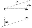
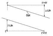
도 9a 및 도 9b를 참조하면, 3 레벨 신호(3LP)에 의해 액정 응답특성(휘도 또는 액정셀 전압)이 변할 때, 가변레벨에 따라 한 프레임의 종료시점(t')에서 응답특성이 다르게 된다. 가변레벨(VL3)이 원하는 수준보다 크거나 작으면, 그 때의 액정 응답특성(NG1,NG2)은 최적 응답특성(Opt)보다 크거나 작게 된다. 최적 응답특성(Opt)은 한 프레임의 종료시점(t')에서 타겟레벨 또는 미리 설정된 임계값(Lth) 이하로 타겟레벨과 근소한 차이를 가지는 응답특성이다. 변조 데이터 전압은 도 10a 및 도 10b와 한 프레임의 종료시점(t')과 그 다음 프레임(t'+1f) 사이에 변하는 응답특성이 임계값(Lth) 이하일 때, 즉 최적 응답특성(Opt)일 때의 가 변레벨 전압이다.9A and 9B, when the liquid crystal response characteristic (luminance or liquid crystal cell voltage) is changed by the 3 level signal 3LP, the response characteristic is different at the end point t 'of one frame according to the variable level. . If the variable level VL3 is larger or smaller than the desired level, the liquid crystal response characteristics NG1 and NG2 at that time become larger or smaller than the optimum response characteristic Opt. The optimum response characteristic Opt is a response characteristic having a slight difference from the target level at the end point t 'of one frame below the target level or a predetermined threshold Lth. The modulation data voltage is determined when the response characteristic that varies between FIGS. 10A and 10B and the end point t 'of one frame and the next frame t' + 1f is equal to or less than the threshold Lth, that is, the optimum response characteristic Opt. Is the variable level voltage.
이렇게 각 온도별로 설정된 최적 변조 데이터는 룩업 테이블(Look-up table)에 저장된다. 저온에서 최적으로 설정된 변조 데이터는 저온 룩업 테이블에, 상온에서 최적으로 설정된 변조 데이터는 상온 룩업 테이블에 그리고 고온에서 최적으로 설정된 변조 데이터들은 고온 룩업 테이블에 등재되고 각각의 룩업 테이블은 메모리에 저장된다.The optimal modulation data set for each temperature is stored in a look-up table. The modulation data optimally set at low temperature is stored in the low temperature lookup table, the modulation data optimally set at room temperature is stored in the normal temperature lookup table, and the modulation data optimally set at high temperature is stored in the high temperature lookup table and each lookup table is stored in the memory.
도 11은 본 발명의 실시예에 따른 액정표시장치를 나타낸다.11 illustrates a liquid crystal display according to an exemplary embodiment of the present invention.
도 11을 참조하면, 본 발명의 실시예에 따른 액정표시장치는 데이터라인(115)과 게이트라인(116)이 교차되며 그 교차부에 액정셀(Clc)을 구동하기 위한 TFT가 형성된 액정표시패널(117)과, 액정표시패널(117)의 온도를 감지하기 위한 온도센서(118)와, 액정표시패널(117)의 데이터라인(115)에 데이터를 공급하기 위한 데이터 구동부(113)와, 액정표시패널(117)의 게이트라인(116)에 스캔펄스를 공급하기 위한 게이트 구동부(114)와, 온도별로 데이터(RGB)를 변조하기 위한 온도별 데이터 변조기(112)를 구비한다.Referring to FIG. 11, in the liquid crystal display according to the exemplary embodiment, a liquid crystal display panel in which a
액정표시패널(117)은 두 장의 유리기판 사이에 액정이 주입되며, 그 하부 유리기판 상에 데이터라인들(115)과 게이트라인들(116)이 상호 직교되도록 형성된다. 데이터라인들(115)과 게이트라인들(116)의 교차부에 형성된 TFT는 게이트라인(116)으로부터의 스캔펄스에 응답하여 데이터라인들(115) 상의 데이터를 액정셀(Clc)에 공급하게 된다. 이를 위하여, TFT의 게이트전극은 게이트라인(116)에 접속되며, 소스전극은 데이터라인(115)에 접속된다. 그리고 TFT의 드레인전극은 액정셀(Clc) 의 화소전극에 접속된다. 또한, 액정표시패널(117)의 하부유리기판 상에는 액정셀(Clc)의 전압을 유지시키기 위한 스토리지 캐패시터(Storage Capacitor : Cst)가 형성된다. 이 스토리지 캐패시터는 k(단, k는 임의의 양의 정수) 번째 게이트라인(116)에 접속된 액정셀(Clc)과 k-1 번째의 전단 게이트라인(116) 사이에 형성될 수도 있으며, k 번째 게이트라인(116)에 접속된 액정셀(Clc)과 별도의 공통라인 사이에 형성될 수도 있다.In the liquid
온도센서(118)는 액정표시패널(117)의 주변에 설치되거나 액정표시패널(117)의 기판 상에 실장되어 액정표시패널(117)과 그 주변의 사용온도를 감지하고 그 온도를 지시하는 온도감지신호를 발생한다. 온도감지신호는 감도를 높이기 위하여 신호증폭기 및 ADC(119)를 통해 증폭되고 디지털 데이터로 변환되어 온도별 데이터 변조기(112)에 공급된다.The
데이터 구동부(113)는 데이터 제어신호(DDC)의 도트클럭을 샘플링하기 위한 쉬프트레지스터, 데이터를 일시저장하기 위한 레지스터, 쉬프트레지스터로부터의 클럭신호에 응답하여 데이터를 1 라인분씩 저장하고 저장된 1 라인분의 데이터를 동시에 출력하기 위한 래치, 래치로부터의 디지털 데이터값에 대응하여 정극성/부극성의 감마전압을 선택하기 위한 디지털/아날로그 변환기, 정극성/부극성 감마전압에 의해 변환된 아날로그 데이터가 공급되는 데이터라인(115)을 선택하기 위한 멀티플렉서 및 멀티플렉서와 데이터라인 사이에 접속된 출력버퍼 등으로 구성된다. 이 데이터 구동부(113)는 온도별 데이터 변조기(112)로부터 출력되는 변조 데이터(MRGB(St))를 입력 받고 그 변조 데이터(MRGB(St))를 타이밍 콘트롤러(111) 의 제어 하에 액정표시패널(117)의 데이터라인들(115)에 공급하게 된다.The
게이트 구동부(114)는 타이밍 콘트롤러(111)로부터의 게이트 제어신호(GDC)에 응답하여 스캔펄스를 순차적으로 발생하는 쉬프트 레지스터, 스캔펄스의 전압을 액정셀(Clc)의 구동에 적합한 레벨로 쉬프트 시키기 위한 레벨 쉬프터, 출력버퍼 등으로 구성된다. 이 게이트 구동부(114)는 스캔펄스를 게이트라인(116)에 공급함으로써 그 게이트라인(116)에 접속된 TFT들을 턴-온(Turn-on)시켜 1 수평라인의 액정셀(Clc)을 선택한다. 데이터 구동부(113)로부터 발생되는 데이터는 스캔펄스에 동기됨으로써 선택된 1 수평라인의 액정셀(Clc)에 공급된다.The
타이밍 콘트롤러(111)는 수직/수평 동기신호(V,H)와 클럭(CLK)을 이용하여 게이트 구동부(114)를 제어하기 위한 게이트 제어신호(GDC)와 데이터 구동부(113)를 제어하기 위한 데이터 제어신호(DDC)를 발생한다. 그리고 타이밍 콘트롤러(111)는 온도별 데이터 변조기(112)에 디지털 비디오 데이터(RGB)를 공급하고 온도별 데이터 변조기(112)의 동작 타이밍을 제어한다.The
온도별 데이터 변조기(112)에는 도 8의 온도별 최적 데이터 검색 알고리즘으로 검색된 온도별 변조 데이터가 미리 저장되어 있다. 이 온도별 데이터 변조기(112)는 온도센서(118)에 의해 감지된 액정표시패널(117)의 온도에 따라 그 온도에 대응하는 최적 변조 데이터를 선택하고 선택된 최적 변조 데이터를 데이터 구동부(113)에 공급한다.The temperature-modulated
온도별 데이터 변조기(112)에 룩업 테이블 형태로 저장된 변조 데이터들은 온도에 따라 그 값이 다르지만 온도에 관계없이 아래의 관계식 ① 내지 ③을 만족 하게 된다.Modulated data stored in the look-up table form in the temperature-
VDn < VDn-1 ---> MVDn < VDn -------- ①VDn <VDn-1 ---> MVDn <VDn -------- ①
VDn = VDn-1 ---> MVDn = VDn, -------- ②VDn = VDn-1 ---> MVDn = VDn, -------- ②
VDn > VDn-1 ---> MVDn > VDn. -------- ③VDn> VDn-1 ---> MVDn> VDn. -------- ③
① 내지 ③에 있어서, VDn-1은 이전 프레임(Fn)의 데이터전압, VDn은 현재 프레임(Fn)의 데이터전압, 그리고 MVDn은 변조 데이터 전압을 각각 나타낸다.In (1) to (3), VDn-1 represents the data voltage of the previous frame Fn, VDn represents the data voltage of the current frame Fn, and MVDn represents the modulated data voltage, respectively.
도 12는 온도별 데이터 변조기(112)를 상세히 나타낸다.12 shows the temperature-
도 12를 참조하면, 온도별 데이터 변조기(112)는 최하위 비트들의 데이터(RGB(LSB))를 바이패스시키기 위한 하위 비트 버스라인(121)과, 상위 비트 버스라인(122)에 접속된 프레임 메모리(123)와, 상위 비트 버스라인(122)과 프레임 메모리(123)에 접속된 선택기(125)와, 선택기(125)와 상위 비트 출력라인(126) 사이에 접속된 제1 내지 제3 룩업 테이블(124a, 124b, 124c)을 구비한다.Referring to FIG. 12, the temperature-
하위 비트 버스라인(121)을 통해 바이패스되는 하위 비트들의 데이터(RGB(MSB))는 소스 데이터가 8 비트일 때 하위 4 비트들을 포함할 수 있다.The lower bit data RGB (MSB) bypassed through the lower
프레임 메모리(123)는 상위 비트들(MSB)을 1 프레임기간 동안 저장하고 저장된 데이터를 선택기(125)에 공급함으로써 상위 비트들(MSB)을 1 프레임기간 동안 지연시켜 선택기(125)에 공급한다. 상위 비트들(MSB)은 소스 데이터가 8 비트일 때 상위 4 비트를 포함할 수 있다.The
선택기(125)는 온도감지신호(St)에 응답하여 상위 비트 버스라인(122)을 경유하여 입력되는 현재 프레임(Fn)의 상위 비트 데이터들(RGB(MSB))과 프레임 메모 리(123)로부터 입력되는 이전 프레임(Fn-1)의 상위 비트 데이터들(RGB(MSB))을 제1 내지 제3 룩업 테이블(124a 내지 124c) 중 어느 하나에 공급한다. 액정표시패널(117)의 현재 온도가 고온(40℃∼70℃)이면 선택기(125)는 고온의 온도감지신호(St)에 응답하여 현재 프레임(Fn)의 상위 비트 데이터들(RGB(MSB))과 이전 프레임(Fn-1)의 상위 비트 데이터들(RGB(MSB))을 제1 룩업 테이블(124a)에 공급한다. 액정표시패널(117)의 현재 온도가 상온(15℃∼35℃)이면 선택기(125)는 상온의 온도감지신호(St)에 응답하여 현재 프레임(Fn)의 상위 비트 데이터들(RGB(MSB))과 이전 프레임(Fn-1)의 상위 비트 데이터들(RGB(MSB))을 제2 룩업 테이블(124b)에 공급한다. 그리고 액정표시패널(117)의 현재 온도가 저온(-20℃∼10℃)이면 선택기(125)는 저온의 온도감지신호(St)에 응답하여 현재 프레임(Fn)의 상위 비트 데이터들(RGB(MSB))과 이전 프레임(Fn-1)의 상위 비트 데이터들(RGB(MSB))을 제3 룩업 테이블(124b)에 공급한다.The
제1 룩업 테이블(124a)에는 고온(40℃∼70℃)에서 실시되는 도 8과 같은 온도별 최적 데이터 검색 알고리즘에서 검색된 고온의 최적 변조 데이터들이 저장된다. 이 제1 룩업 테이블(124a)은 액정표시패널(117)의 현재 온도가 고온(40℃∼70℃)일 때 현재 프레임(Fn)의 상위 비트 데이터들(RGB(MSB))과 이전 프레임(Fn-1)의 상위 비트 데이터들(RGB(MSB))을 비교하고 그 비교결과에 따라 미리 저장된 고온의 최적 변조 데이터를 선택한다.The first lookup table 124a stores optimum modulation data of the high temperature retrieved by the optimum data search algorithm for each temperature as shown in FIG. 8 performed at a high temperature (40 ° C to 70 ° C). The first lookup table 124a includes the upper bit data RGB (MSB) of the current frame Fn and the previous frame Fn when the current temperature of the liquid
제2 룩업 테이블(124b)에는 상온(15℃∼35℃)에서 실시되는 도 8과 같은 온도별 최적 데이터 검색 알고리즘에서 검색된 상온의 최적 변조 데이터들이 저장된 다. 이 제2 룩업 테이블(124b)은 액정표시패널(117)의 현재 온도가 상온(15℃∼35℃)일 때 현재 프레임(Fn)의 상위 비트 데이터들(RGB(MSB))과 이전 프레임(Fn-1)의 상위 비트 데이터들(RGB(MSB))을 비교하고 그 비교결과에 따라 미리 저장된 상온의 최적 변조 데이터를 선택하여 출력한다. 이 제2 룩업 테이블(124b)에 저장된 변조 데이터를 이용하여 상온 예컨대, 25℃에서 소스 데이터를 변조 데이터(MRGB)로 변조하여 데이터 구동부(113)에 공급하면 액정의 응답속도는 표 5와 같다.The second lookup table 124b stores optimal modulation data of room temperature searched by the optimum data search algorithm for each temperature shown in FIG. 8 performed at room temperature (15 ° C to 35 ° C). The second lookup table 124b includes the upper bit data RGB (MSB) of the current frame Fn and the previous frame Fn when the current temperature of the liquid
제3 룩업 테이블(124c)에는 저온(-20℃∼10℃)에서 실시되는 도 8과 같은 온도별 최적 데이터 검색 알고리즘에서 검색된 저온의 최적 변조 데이터들이 저장된다. 이 제3 룩업 테이블(124c)은 액정표시패널(117)의 현재 온도가 저온(-20℃∼10℃)일 때 현재 프레임(Fn)의 상위 비트 데이터들(RGB(MSB))과 이전 프레임(Fn-1)의 상위 비트 데이터들(RGB(MSB))을 비교하고 그 비교결과에 따라 미리 저장된 저온의 최적 변조 데이터를 선택하여 출력한다. 이 제3 룩업 테이블(124c)에 저장된 변조 데이터를 이용하여 저온 예컨대, 0℃에서 소스 데이터를 변조 데이터(MRGB)로 변조하여 데이터 구동부(113)에 공급하면 액정의 응답속도는 아래의 표 6과 같다. 표 6은 0℃에서 도 8과 같은 온도별 최적 데이터 검색 알고리즘에서 검색된 저온의 최적 변조 데이터들을 이용하여 본원 출원인에 의해 제작되고 시판되고 있는 해상도 1280×768의 30" 액정표시모듈을 구동하였을 때 계조 0(G0), 63(G63), 127(G127), 191(G191), 255(G255) 각각에서의 라이징 타임과 폴링 타임에서의 액정 응답속도[ms]를 나타낸다.The third lookup table 124c stores the optimum modulation data of the low temperature retrieved by the optimum data search algorithm for each temperature as shown in FIG. 8 performed at a low temperature (-20 ° C to 10 ° C). The third lookup table 124c includes the upper bit data RGB (MSB) of the current frame Fn and the previous frame when the current temperature of the liquid

표 4 및 표 6에서 알 수 있는 바, 본 발명의 따른 액정표시소자는 저온에서도 응답속도가 빠르게 된다. 또한, 본 발명의 따른 액정표시소자는 도 8과 같은 온도별 최적 데이터 검색 알고리즘을 이용하여 고온, 상온, 저온의 온도별로 최적의 변조 데이터를 검색하여 룩업 테이블로 구성하고 액정표시패널(117)의 온도에 따라 룩업 테이블에서 온도별 최적 변조 데이터를 선택하여 소스 데이터를 변조함으로써 액정표시패널(117)의 사용 온도가 바뀌더라도 최적의 화질을 유지할 수 있다.As can be seen from Table 4 and Table 6, the liquid crystal display device according to the present invention has a fast response speed even at low temperatures. In addition, the liquid crystal display device according to the present invention searches for the optimal modulation data for each temperature of the high temperature, room temperature, and low temperature by using the optimum data search algorithm for each temperature as shown in FIG. By selecting the optimum modulation data for each temperature in the lookup table according to the temperature and modulating the source data, the optimum image quality can be maintained even when the use temperature of the liquid
도 12와 같이 소스 데이터에서 상위 비트 데이터들(RGB(MSB))만을 변조하면 룩업 테이블(124a, 124b, 124c)의 크기와 그 룩업 테이블(124a, 124b, 124c)이 저장되는 메모리의 용량을 줄일 수 있다.Modulating only the upper bit data RGB (MSB) from the source data as shown in FIG. 12 reduces the size of the lookup tables 124a, 124b, and 124c and the memory capacity of the lookup tables 124a, 124b, and 124c. Can be.
도 13은 온도별 데이터 변조기(112)의 다른 실시예를 나타낸다.13 illustrates another embodiment of a temperature-
이 실시예의 온도별 데이터 변조기(112)는 소스 데이터를 풀비트로 변조하여 화질을 더 높일 수 있다.The temperature-specific data modulator 112 of this embodiment may further improve image quality by modulating the source data into full bits.
도 13을 참조하면, 온도별 데이터 변조기(112)는 풀비트의 소스 데이터 버스라인(131)에 접속된 프레임 메모리(133)와, 소스 데이터 버스라인(131)과 프레임 메모리(133)에 접속된 선택기(135)와, 선택기(135)와 변조 데이터 출력라인(136) 사이에 접속된 제1 내지 제3 룩업 테이블(134a, 134b, 134c)을 구비한다.Referring to FIG. 13, a temperature-
프레임 메모리(133)는 8 비트의 소스 데이터들(RGB)을 1 프레임기간 동안 저장하고 저장된 데이터를 선택기(125)에 공급함으로써 소스 데이터들(RGB)을 1 프레임기간 동안 지연시켜 선택기(125)에 공급한다.The
선택기(135)는 온도감지신호(St)에 응답하여 소스 데이터 버스라인(131)을 경유하여 입력되는 현재 프레임(Fn)의 소스 데이터들(RGB)과 프레임 메모리(133)로부터 입력되는 이전 프레임(Fn-1)의 소스 데이터들(RGB)을 제1 내지 제3 룩업 테이블(134a 내지 134c) 중 어느 하나에 공급한다. 액정표시패널(117)의 현재 온도가 고온(40℃∼70℃)이면 선택기(135)는 고온의 온도감지신호(St)에 응답하여 현재 프레임(Fn)의 소스 데이터들(RGB)과 이전 프레임(Fn-1)의 소스 데이터들(RGB)을 제1 룩업 테이블(134a)에 공급한다. 액정표시패널(117)의 현재 온도가 상온(15℃∼35℃)이면 선택기(135)는 상온의 온도감지신호(St)에 응답하여 현재 프레임(Fn)의 소스 데이터들(RGB)과 이전 프레임(Fn-1)의 소스 데이터들(RGB)을 제2 룩업 테이블(134b)에 공급한다. 그리고 액정표시패널(117)의 현재 온도가 저온(-20℃∼10℃)이면 선택기(135)는 저온의 온도감지신호(St)에 응답하여 현재 프레임(Fn)의 소스 데이터들(RGB)과 이전 프레임(Fn-1)의 소스 데이터들(RGB)을 제3 룩업 테이블(124c)에 공급한다.The
제1 룩업 테이블(134a)은 액정표시패널(117)의 현재 온도가 고온(40℃∼70℃)일 때 선택기(135)로부터 입력되는 현재 프레임(Fn)과 이전 프레임(Fn-1)의 소스 데이터들(RGB)을 비교하고 그 비교결과에 따라 미리 저장된 고온의 최적 변조 데이터를 선택한다.The first lookup table 134a is a source of the current frame Fn and the previous frame Fn-1 input from the
제2 룩업 테이블(134b)은 액정표시패널(117)의 현재 온도가 상온(15℃∼35℃)일 때 선택기(135)로부터 입력되는 현재 프레임(Fn)과 이전 프레임(Fn-1)의 소스 데이터들(RGB)을 비교하고 그 비교결과에 따라 미리 저장된 상온의 최적 변조 데이터를 선택한다.The second lookup table 134b is a source of the current frame Fn and the previous frame Fn-1 input from the
제3 룩업 테이블(134c)은 액정표시패널(117)의 현재 온도가 저온(-20℃∼10℃)일 때 선택기(135)로부터 입력되는 현재 프레임(Fn)과 이전 프레임(Fn-1)의 소스 데이터들(RGB)을 비교하고 그 비교결과에 따라 미리 저장된 저온의 최적 변조 데이터를 선택한다.
The third lookup table 134c includes the current frame Fn and the previous frame Fn-1 that are input from the
상술한 바와 같이, 본 발명에 따른 액정의 응답속도 측정방법 및 장치는 3 레벨 신호를 이용하여 액정표시패널의 주변온도를 바꾸면서 각 계조의 최적 변조 데이터를 자동으로 검색함으로써 각 온도별로 액정의 응답속도를 빠르게 하기 위한 최적의 변조 데이터를 자동으로 도출할 수 있다. 또한, 본 발명에 따른 액정표시소자의 구동방법 및 장치는 상기 액정의 응답속도 측정방법 및 장치에 의해 도출된 온도별 최적 변조 데이터를 룩업 테이블로 구성하고 온도센서를 통해 감지된 액정표시패널의 온도에 적합한 최적의 변조 데이터를 상기 룩업 테이블에서 선택하여 소스 데이터를 변조함으로써 액정표시소자의 사용온도가 변할 때 발생되는 화질의 저하를 최소화할 수 있다.As described above, the method and apparatus for measuring the response speed of a liquid crystal according to the present invention automatically retrieves the optimum modulation data of each gray level by changing the ambient temperature of the liquid crystal display panel using a three-level signal, thereby responsiveness of the liquid crystal for each temperature. Automatically derive optimal modulation data to speed up In addition, the method and apparatus for driving a liquid crystal display according to the present invention comprise a look-up table of temperature-optimized modulation data derived by the method and device for measuring a response speed of the liquid crystal, and detects the temperature of the liquid crystal display panel using a temperature sensor. Degradation of the image quality generated when the use temperature of the liquid crystal display device is changed by selecting the optimal modulation data suitable for the data from the lookup table and modulating the source data can be minimized.
이상 설명한 내용을 통해 당업자라면 본 발명의 기술사상을 일탈하지 아니하는 범위에서 다양한 변경 및 수정이 가능함을 알 수 있을 것이다. 따라서, 본 발명의 기술적 범위는 명세서의 상세한 설명에 기재된 내용으로 한정되는 것이 아니라 특허 청구의 범위에 의해 정하여 져야만 할 것이다.Those skilled in the art will appreciate that various changes and modifications can be made without departing from the technical spirit of the present invention. Therefore, the technical scope of the present invention should not be limited to the contents described in the detailed description of the specification but should be defined by the claims.
Claims (14)
Translated fromKoreanPriority Applications (5)
| Application Number | Priority Date | Filing Date | Title |
|---|---|---|---|
| KR1020030043805AKR100954333B1 (en) | 2003-06-30 | 2003-06-30 | Method and device for measuring response speed of liquid crystal and method and device for driving liquid crystal display device using same |
| US10/874,547US7446749B2 (en) | 2003-06-30 | 2004-06-24 | Method and apparatus for measuring response time of liquid crystal, and method and apparatus for driving liquid crystal display device using the same |
| CNB2004100694131ACN100545662C (en) | 2003-06-30 | 2004-06-28 | Liquid crystal display driving method and device |
| JP2004192226AJP3885069B2 (en) | 2003-06-30 | 2004-06-29 | Method and apparatus for measuring response time of liquid crystal |
| JP2006219598AJP4889407B2 (en) | 2003-06-30 | 2006-08-11 | Method and apparatus for driving liquid crystal display element |
Applications Claiming Priority (1)
| Application Number | Priority Date | Filing Date | Title |
|---|---|---|---|
| KR1020030043805AKR100954333B1 (en) | 2003-06-30 | 2003-06-30 | Method and device for measuring response speed of liquid crystal and method and device for driving liquid crystal display device using same |
Publications (2)
| Publication Number | Publication Date |
|---|---|
| KR20050002427A KR20050002427A (en) | 2005-01-07 |
| KR100954333B1true KR100954333B1 (en) | 2010-04-21 |
Family
ID=33536411
Family Applications (1)
| Application Number | Title | Priority Date | Filing Date |
|---|---|---|---|
| KR1020030043805AExpired - Fee RelatedKR100954333B1 (en) | 2003-06-30 | 2003-06-30 | Method and device for measuring response speed of liquid crystal and method and device for driving liquid crystal display device using same |
Country Status (4)
| Country | Link |
|---|---|
| US (1) | US7446749B2 (en) |
| JP (2) | JP3885069B2 (en) |
| KR (1) | KR100954333B1 (en) |
| CN (1) | CN100545662C (en) |
Cited By (1)
| Publication number | Priority date | Publication date | Assignee | Title |
|---|---|---|---|---|
| US12057048B2 (en) | 2022-06-20 | 2024-08-06 | Samsung Display Co., Ltd. | Display device having scale factor provider controlled by temperature sensor, current sensor, and power controller and method of driving the same |
Families Citing this family (67)
| Publication number | Priority date | Publication date | Assignee | Title |
|---|---|---|---|---|
| US7064740B2 (en) | 2001-11-09 | 2006-06-20 | Sharp Laboratories Of America, Inc. | Backlit display with improved dynamic range |
| WO2005052673A2 (en) | 2003-11-21 | 2005-06-09 | Sharp Laboratories Of America, Inc. | Liquid crystal display with adaptive color |
| KR100875326B1 (en)* | 2003-12-18 | 2008-12-22 | 샤프 가부시키가이샤 | Liquid crystal display response characteristics determination method and presentation method |
| US7532192B2 (en) | 2004-05-04 | 2009-05-12 | Sharp Laboratories Of America, Inc. | Liquid crystal display with filtered black point |
| US7612757B2 (en) | 2004-05-04 | 2009-11-03 | Sharp Laboratories Of America, Inc. | Liquid crystal display with modulated black point |
| US7777714B2 (en) | 2004-05-04 | 2010-08-17 | Sharp Laboratories Of America, Inc. | Liquid crystal display with adaptive width |
| US7602369B2 (en) | 2004-05-04 | 2009-10-13 | Sharp Laboratories Of America, Inc. | Liquid crystal display with colored backlight |
| US7872631B2 (en) | 2004-05-04 | 2011-01-18 | Sharp Laboratories Of America, Inc. | Liquid crystal display with temporal black point |
| US8395577B2 (en) | 2004-05-04 | 2013-03-12 | Sharp Laboratories Of America, Inc. | Liquid crystal display with illumination control |
| US7505018B2 (en) | 2004-05-04 | 2009-03-17 | Sharp Laboratories Of America, Inc. | Liquid crystal display with reduced black level insertion |
| US7023451B2 (en) | 2004-06-14 | 2006-04-04 | Sharp Laboratories Of America, Inc. | System for reducing crosstalk |
| JP4523348B2 (en)* | 2004-07-06 | 2010-08-11 | 株式会社 日立ディスプレイズ | Display device and driving method thereof |
| US7556836B2 (en) | 2004-09-03 | 2009-07-07 | Solae, Llc | High protein snack product |
| KR101056371B1 (en)* | 2004-09-08 | 2011-08-11 | 삼성전자주식회사 | Display device, driving method and device thereof |
| US7898519B2 (en) | 2005-02-17 | 2011-03-01 | Sharp Laboratories Of America, Inc. | Method for overdriving a backlit display |
| US8643595B2 (en) | 2004-10-25 | 2014-02-04 | Sipix Imaging, Inc. | Electrophoretic display driving approaches |
| US8050511B2 (en) | 2004-11-16 | 2011-11-01 | Sharp Laboratories Of America, Inc. | High dynamic range images from low dynamic range images |
| US7525528B2 (en) | 2004-11-16 | 2009-04-28 | Sharp Laboratories Of America, Inc. | Technique that preserves specular highlights |
| US8050512B2 (en) | 2004-11-16 | 2011-11-01 | Sharp Laboratories Of America, Inc. | High dynamic range images from low dynamic range images |
| KR20060073741A (en)* | 2004-12-24 | 2006-06-29 | 삼성전자주식회사 | Response speed measuring device and response speed measuring method using the same |
| JP2006195231A (en)* | 2005-01-14 | 2006-07-27 | Kawasaki Microelectronics Kk | Overdrive circuit and liquid crystal panel driving device |
| CN100350304C (en)* | 2005-04-19 | 2007-11-21 | 浙江大学 | Liquid crystal display response time electrooptical automatic measuring instrument |
| DE102006032262A1 (en)* | 2005-07-15 | 2007-05-03 | Samsung Electronics Co., Ltd., Suwon | A temperature sensor for a display device, a thin film transistor array panel including the temperature sensor, a liquid crystal display, a liquid crystal display drive circuit, and a liquid crystal display flicker control system |
| JP4241702B2 (en)* | 2005-09-29 | 2009-03-18 | エプソンイメージングデバイス株式会社 | LIQUID CRYSTAL DEVICE, LIGHT EMITTING DEVICE, ELECTRONIC DEVICE, LIQUID CRYSTAL DEVICE CONTROL METHOD, AND LIGHT EMITTING DEVICE CONTROL METHOD |
| US9143657B2 (en) | 2006-01-24 | 2015-09-22 | Sharp Laboratories Of America, Inc. | Color enhancement technique using skin color detection |
| US8121401B2 (en) | 2006-01-24 | 2012-02-21 | Sharp Labortories of America, Inc. | Method for reducing enhancement of artifacts and noise in image color enhancement |
| JP5255186B2 (en)* | 2006-02-20 | 2013-08-07 | Necディスプレイソリューションズ株式会社 | Image display device and method for optimizing overdrive coefficient in image display device |
| KR101243817B1 (en)* | 2006-07-28 | 2013-03-18 | 엘지디스플레이 주식회사 | Flat panel display and data multi-modulation method thereof |
| US7714981B2 (en) | 2006-10-30 | 2010-05-11 | Asml Netherlands B.V. | Lithographic apparatus and method |
| US8941580B2 (en) | 2006-11-30 | 2015-01-27 | Sharp Laboratories Of America, Inc. | Liquid crystal display with area adaptive backlight |
| JP5348751B2 (en) | 2007-01-25 | 2013-11-20 | 株式会社東陽テクニカ | Method for measuring physical properties of TFT liquid crystal panel and device for measuring physical properties of TFT liquid crystal panel |
| KR101386264B1 (en)* | 2007-02-28 | 2014-04-30 | 엘지디스플레이 주식회사 | Apparatus of setting automatically over-driving look-up table for liquid crystal display device and control method thereof |
| US8274472B1 (en) | 2007-03-12 | 2012-09-25 | Sipix Imaging, Inc. | Driving methods for bistable displays |
| US8243013B1 (en) | 2007-05-03 | 2012-08-14 | Sipix Imaging, Inc. | Driving bistable displays |
| US20080303780A1 (en)* | 2007-06-07 | 2008-12-11 | Sipix Imaging, Inc. | Driving methods and circuit for bi-stable displays |
| WO2009049204A1 (en)* | 2007-10-12 | 2009-04-16 | Sipix Imaging, Inc. | Approach to adjust driving waveforms for a display device |
| TW200921606A (en)* | 2007-11-02 | 2009-05-16 | Qisda Corp | Compensation device, method, and electronic system utilizing the same |
| US8462102B2 (en) | 2008-04-25 | 2013-06-11 | Sipix Imaging, Inc. | Driving methods for bistable displays |
| KR101521649B1 (en)* | 2008-06-10 | 2015-05-19 | 엘지디스플레이 주식회사 | Liquid crystal display |
| JP2010014941A (en)* | 2008-07-03 | 2010-01-21 | Hitachi Displays Ltd | Display device |
| KR101490894B1 (en)* | 2008-10-02 | 2015-02-09 | 삼성전자주식회사 | Display apparatus and timing controller for calibrating grayscale data, and panel driving method using the same |
| US8558855B2 (en)* | 2008-10-24 | 2013-10-15 | Sipix Imaging, Inc. | Driving methods for electrophoretic displays |
| US9019318B2 (en)* | 2008-10-24 | 2015-04-28 | E Ink California, Llc | Driving methods for electrophoretic displays employing grey level waveforms |
| US9251736B2 (en) | 2009-01-30 | 2016-02-02 | E Ink California, Llc | Multiple voltage level driving for electrophoretic displays |
| US20100194733A1 (en)* | 2009-01-30 | 2010-08-05 | Craig Lin | Multiple voltage level driving for electrophoretic displays |
| US9460666B2 (en)* | 2009-05-11 | 2016-10-04 | E Ink California, Llc | Driving methods and waveforms for electrophoretic displays |
| US8576164B2 (en)* | 2009-10-26 | 2013-11-05 | Sipix Imaging, Inc. | Spatially combined waveforms for electrophoretic displays |
| US11049463B2 (en) | 2010-01-15 | 2021-06-29 | E Ink California, Llc | Driving methods with variable frame time |
| US8558786B2 (en)* | 2010-01-20 | 2013-10-15 | Sipix Imaging, Inc. | Driving methods for electrophoretic displays |
| US9224338B2 (en) | 2010-03-08 | 2015-12-29 | E Ink California, Llc | Driving methods for electrophoretic displays |
| US9013394B2 (en) | 2010-06-04 | 2015-04-21 | E Ink California, Llc | Driving method for electrophoretic displays |
| KR101303456B1 (en) | 2010-06-22 | 2013-09-10 | 엘지디스플레이 주식회사 | 3 dimensional data modulation method and liquid crystal display device using the same |
| TWI598672B (en) | 2010-11-11 | 2017-09-11 | 希畢克斯幻像有限公司 | Driving method for electrophoretic displays |
| CN103308330B (en)* | 2012-03-14 | 2017-08-01 | 富泰华工业(深圳)有限公司 | Test device and test method for electronic product performance |
| KR102090715B1 (en)* | 2013-08-02 | 2020-03-19 | 삼성디스플레이 주식회사 | Method and apparatus for measuring capacitance of organic light emitting device |
| US10380931B2 (en) | 2013-10-07 | 2019-08-13 | E Ink California, Llc | Driving methods for color display device |
| TWI550332B (en) | 2013-10-07 | 2016-09-21 | 電子墨水加利福尼亞有限責任公司 | Driving methods for color display device |
| US10726760B2 (en) | 2013-10-07 | 2020-07-28 | E Ink California, Llc | Driving methods to produce a mixed color state for an electrophoretic display |
| USD742770S1 (en) | 2014-01-06 | 2015-11-10 | Greenwave Systems Pte. Ltd. | Enclosure for electronic device |
| US9997121B2 (en)* | 2015-05-21 | 2018-06-12 | Apple Inc. | Display with physically modeled charge accumulation tracking |
| CN105353088B (en)* | 2015-11-12 | 2017-11-10 | 湖北大学 | Automatically controlled light-scattering material and device time domain response characteristic test method |
| CN107092117B (en)* | 2017-06-29 | 2019-11-12 | 京东方科技集团股份有限公司 | Display panel and method for improving display quality of display panel |
| US10339881B1 (en)* | 2017-12-28 | 2019-07-02 | Shenzhen China Star Optoelectronics Technology Co., Ltd. | Method of acquiring overdrive look-up table of liquid crystal display |
| CN114114725B (en)* | 2020-08-28 | 2024-11-15 | 深圳莱宝高科技股份有限公司 | A method for testing LCM response time and related equipment |
| KR20230053196A (en)* | 2021-10-14 | 2023-04-21 | 주식회사 엘엑스세미콘 | Driving circuit for display |
| CN115128853B (en)* | 2022-06-17 | 2023-10-17 | 京东方科技集团股份有限公司 | Response time testing method and system for liquid crystal phase shifter and driving method |
| CN117174044A (en)* | 2023-07-26 | 2023-12-05 | 重庆惠科金渝光电科技有限公司 | Method, system and display panel for reducing liquid crystal response time |
Citations (2)
| Publication number | Priority date | Publication date | Assignee | Title |
|---|---|---|---|---|
| JPH085974A (en)* | 1994-06-17 | 1996-01-12 | Casio Comput Co Ltd | LCD test equipment |
| KR20030048529A (en)* | 2001-12-12 | 2003-06-25 | 엘지.필립스 엘시디 주식회사 | Method and apparatus for driving liquid crystal display |
Family Cites Families (9)
| Publication number | Priority date | Publication date | Assignee | Title |
|---|---|---|---|---|
| NL9002516A (en) | 1990-11-19 | 1992-06-16 | Philips Nv | DISPLAY DEVICE AND METHOD OF MANUFACTURE THEREOF. |
| DE69616621D1 (en)* | 1995-03-22 | 2001-12-13 | Canon Kk | Display device with even temperature distribution over the screen |
| EP0927416A1 (en) | 1997-07-22 | 1999-07-07 | Koninklijke Philips Electronics N.V. | Display device |
| JP2001331154A (en) | 2000-05-23 | 2001-11-30 | Matsushita Electric Ind Co Ltd | Liquid crystal display device and liquid crystal display method |
| JP3769463B2 (en) | 2000-07-06 | 2006-04-26 | 株式会社日立製作所 | Display device, image reproducing device including display device, and driving method thereof |
| KR100363540B1 (en) | 2000-12-21 | 2002-12-05 | 삼성전자 주식회사 | Fast driving liquid crystal display and gray voltage generating circuit for the same |
| KR100835928B1 (en)* | 2001-12-13 | 2008-06-09 | 엘지디스플레이 주식회사 | Method and apparatus for measuring the response speed of liquid crystal |
| US7038647B2 (en)* | 2002-03-25 | 2006-05-02 | Sharp Kabushiki Kaisha | Liquid crystal display apparatus |
| JP4425643B2 (en) | 2003-02-10 | 2010-03-03 | シャープ株式会社 | Evaluation apparatus for liquid crystal display device, liquid crystal display device, and evaluation method for liquid crystal display device |
- 2003
- 2003-06-30KRKR1020030043805Apatent/KR100954333B1/ennot_activeExpired - Fee Related
- 2004
- 2004-06-24USUS10/874,547patent/US7446749B2/ennot_activeExpired - Fee Related
- 2004-06-28CNCNB2004100694131Apatent/CN100545662C/ennot_activeExpired - Fee Related
- 2004-06-29JPJP2004192226Apatent/JP3885069B2/ennot_activeExpired - Fee Related
- 2006
- 2006-08-11JPJP2006219598Apatent/JP4889407B2/ennot_activeExpired - Fee Related
Patent Citations (2)
| Publication number | Priority date | Publication date | Assignee | Title |
|---|---|---|---|---|
| JPH085974A (en)* | 1994-06-17 | 1996-01-12 | Casio Comput Co Ltd | LCD test equipment |
| KR20030048529A (en)* | 2001-12-12 | 2003-06-25 | 엘지.필립스 엘시디 주식회사 | Method and apparatus for driving liquid crystal display |
Cited By (1)
| Publication number | Priority date | Publication date | Assignee | Title |
|---|---|---|---|---|
| US12057048B2 (en) | 2022-06-20 | 2024-08-06 | Samsung Display Co., Ltd. | Display device having scale factor provider controlled by temperature sensor, current sensor, and power controller and method of driving the same |
Also Published As
| Publication number | Publication date |
|---|---|
| KR20050002427A (en) | 2005-01-07 |
| US20040263450A1 (en) | 2004-12-30 |
| CN100545662C (en) | 2009-09-30 |
| JP2006313384A (en) | 2006-11-16 |
| JP2005025188A (en) | 2005-01-27 |
| JP4889407B2 (en) | 2012-03-07 |
| JP3885069B2 (en) | 2007-02-21 |
| US7446749B2 (en) | 2008-11-04 |
| CN1576869A (en) | 2005-02-09 |
Similar Documents
| Publication | Publication Date | Title |
|---|---|---|
| KR100954333B1 (en) | Method and device for measuring response speed of liquid crystal and method and device for driving liquid crystal display device using same | |
| KR100815899B1 (en) | Method and apparatus for driving a liquid crystal display | |
| KR100835928B1 (en) | Method and apparatus for measuring the response speed of liquid crystal | |
| US9837031B2 (en) | Apparatus and method for driving liquid crystal display device | |
| KR100815893B1 (en) | Method and apparatus for driving a liquid crystal display | |
| US8284143B2 (en) | Timing controller, liquid crystal display device having the same, and driving method thereof | |
| KR100859391B1 (en) | Display device | |
| US8994760B2 (en) | Liquid crystal display device and method for driving a liquid crystal display device | |
| US8259050B2 (en) | Liquid crystal display device and video processing method thereof | |
| KR20190069668A (en) | Display device capable of grayscale expantion | |
| KR100908655B1 (en) | Modulation method of data supply time and driving method and device of liquid crystal display device using the same | |
| KR101773419B1 (en) | Methode for compensating data and display apparatus performing the method | |
| KR101222535B1 (en) | Liquid crystal display and driving method thereof | |
| KR101408254B1 (en) | Apparatus and method for improving response time of liquid crystal display | |
| KR20090099668A (en) | Driving apparatus and driving method of liquid crystal display | |
| KR100769170B1 (en) | Method and Apparatus For Driving Liquid Crystal Display | |
| KR101222977B1 (en) | Appratus and method for driving LCD | |
| KR20180042603A (en) | Liquid crystal display | |
| KR100982065B1 (en) | LCD and its driving method | |
| KR20100006392A (en) | Liquid crystal display device | |
| KR20100005853A (en) | Over driving circuit and liquid crystal display device using the same and driving method thereof | |
| KR20050066748A (en) | Method and apparatus for driving memory of liquid crystal display device |
Legal Events
| Date | Code | Title | Description |
|---|---|---|---|
| PA0109 | Patent application | St.27 status event code:A-0-1-A10-A12-nap-PA0109 | |
| PG1501 | Laying open of application | St.27 status event code:A-1-1-Q10-Q12-nap-PG1501 | |
| R17-X000 | Change to representative recorded | St.27 status event code:A-3-3-R10-R17-oth-X000 | |
| A201 | Request for examination | ||
| PA0201 | Request for examination | St.27 status event code:A-1-2-D10-D11-exm-PA0201 | |
| PN2301 | Change of applicant | St.27 status event code:A-3-3-R10-R13-asn-PN2301 St.27 status event code:A-3-3-R10-R11-asn-PN2301 | |
| E902 | Notification of reason for refusal | ||
| PE0902 | Notice of grounds for rejection | St.27 status event code:A-1-2-D10-D21-exm-PE0902 | |
| AMND | Amendment | ||
| E13-X000 | Pre-grant limitation requested | St.27 status event code:A-2-3-E10-E13-lim-X000 | |
| P11-X000 | Amendment of application requested | St.27 status event code:A-2-2-P10-P11-nap-X000 | |
| P13-X000 | Application amended | St.27 status event code:A-2-2-P10-P13-nap-X000 | |
| E601 | Decision to refuse application | ||
| PE0601 | Decision on rejection of patent | St.27 status event code:N-2-6-B10-B15-exm-PE0601 | |
| T11-X000 | Administrative time limit extension requested | St.27 status event code:U-3-3-T10-T11-oth-X000 | |
| AMND | Amendment | ||
| E13-X000 | Pre-grant limitation requested | St.27 status event code:A-2-3-E10-E13-lim-X000 | |
| J201 | Request for trial against refusal decision | ||
| P11-X000 | Amendment of application requested | St.27 status event code:A-2-2-P10-P11-nap-X000 | |
| P13-X000 | Application amended | St.27 status event code:A-2-2-P10-P13-nap-X000 | |
| PJ0201 | Trial against decision of rejection | St.27 status event code:A-3-3-V10-V11-apl-PJ0201 | |
| PB0901 | Examination by re-examination before a trial | St.27 status event code:A-6-3-E10-E12-rex-PB0901 | |
| B701 | Decision to grant | ||
| PB0701 | Decision of registration after re-examination before a trial | St.27 status event code:A-3-4-F10-F13-rex-PB0701 | |
| GRNT | Written decision to grant | ||
| PR0701 | Registration of establishment | St.27 status event code:A-2-4-F10-F11-exm-PR0701 | |
| PR1002 | Payment of registration fee | St.27 status event code:A-2-2-U10-U11-oth-PR1002 Fee payment year number:1 | |
| PG1601 | Publication of registration | St.27 status event code:A-4-4-Q10-Q13-nap-PG1601 | |
| R18-X000 | Changes to party contact information recorded | St.27 status event code:A-5-5-R10-R18-oth-X000 | |
| R18-X000 | Changes to party contact information recorded | St.27 status event code:A-5-5-R10-R18-oth-X000 | |
| R18-X000 | Changes to party contact information recorded | St.27 status event code:A-5-5-R10-R18-oth-X000 | |
| FPAY | Annual fee payment | Payment date:20130329 Year of fee payment:4 | |
| PR1001 | Payment of annual fee | St.27 status event code:A-4-4-U10-U11-oth-PR1001 Fee payment year number:4 | |
| PR1001 | Payment of annual fee | St.27 status event code:A-4-4-U10-U11-oth-PR1001 Fee payment year number:5 | |
| PR1001 | Payment of annual fee | St.27 status event code:A-4-4-U10-U11-oth-PR1001 Fee payment year number:6 | |
| FPAY | Annual fee payment | Payment date:20160329 Year of fee payment:7 | |
| PR1001 | Payment of annual fee | St.27 status event code:A-4-4-U10-U11-oth-PR1001 Fee payment year number:7 | |
| FPAY | Annual fee payment | Payment date:20170320 Year of fee payment:8 | |
| PR1001 | Payment of annual fee | St.27 status event code:A-4-4-U10-U11-oth-PR1001 Fee payment year number:8 | |
| PR1001 | Payment of annual fee | St.27 status event code:A-4-4-U10-U11-oth-PR1001 Fee payment year number:9 | |
| FPAY | Annual fee payment | Payment date:20190318 Year of fee payment:10 | |
| PR1001 | Payment of annual fee | St.27 status event code:A-4-4-U10-U11-oth-PR1001 Fee payment year number:10 | |
| PC1903 | Unpaid annual fee | St.27 status event code:A-4-4-U10-U13-oth-PC1903 Not in force date:20200416 Payment event data comment text:Termination Category : DEFAULT_OF_REGISTRATION_FEE | |
| PC1903 | Unpaid annual fee | St.27 status event code:N-4-6-H10-H13-oth-PC1903 Ip right cessation event data comment text:Termination Category : DEFAULT_OF_REGISTRATION_FEE Not in force date:20200416 |