KR100953424B1 - Bidirectional backlight assembly and bidirectional liquid crystal display using the same - Google Patents
Bidirectional backlight assembly and bidirectional liquid crystal display using the sameDownload PDFInfo
- Publication number
- KR100953424B1 KR100953424B1KR1020030042007AKR20030042007AKR100953424B1KR 100953424 B1KR100953424 B1KR 100953424B1KR 1020030042007 AKR1020030042007 AKR 1020030042007AKR 20030042007 AKR20030042007 AKR 20030042007AKR 100953424 B1KR100953424 B1KR 100953424B1
- Authority
- KR
- South Korea
- Prior art keywords
- light
- light guide
- bidirectional
- sub
- liquid crystal
- Prior art date
- Legal status (The legal status is an assumption and is not a legal conclusion. Google has not performed a legal analysis and makes no representation as to the accuracy of the status listed.)
- Expired - Fee Related
Links
Images


Classifications
- G—PHYSICS
- G02—OPTICS
- G02F—OPTICAL DEVICES OR ARRANGEMENTS FOR THE CONTROL OF LIGHT BY MODIFICATION OF THE OPTICAL PROPERTIES OF THE MEDIA OF THE ELEMENTS INVOLVED THEREIN; NON-LINEAR OPTICS; FREQUENCY-CHANGING OF LIGHT; OPTICAL LOGIC ELEMENTS; OPTICAL ANALOGUE/DIGITAL CONVERTERS
- G02F1/00—Devices or arrangements for the control of the intensity, colour, phase, polarisation or direction of light arriving from an independent light source, e.g. switching, gating or modulating; Non-linear optics
- G02F1/01—Devices or arrangements for the control of the intensity, colour, phase, polarisation or direction of light arriving from an independent light source, e.g. switching, gating or modulating; Non-linear optics for the control of the intensity, phase, polarisation or colour
- G02F1/13—Devices or arrangements for the control of the intensity, colour, phase, polarisation or direction of light arriving from an independent light source, e.g. switching, gating or modulating; Non-linear optics for the control of the intensity, phase, polarisation or colour based on liquid crystals, e.g. single liquid crystal display cells
- G02F1/133—Constructional arrangements; Operation of liquid crystal cells; Circuit arrangements
- G02F1/1333—Constructional arrangements; Manufacturing methods
- G02F1/1335—Structural association of cells with optical devices, e.g. polarisers or reflectors
- G02F1/1336—Illuminating devices
- G02F1/133615—Edge-illuminating devices, i.e. illuminating from the side
- G—PHYSICS
- G02—OPTICS
- G02F—OPTICAL DEVICES OR ARRANGEMENTS FOR THE CONTROL OF LIGHT BY MODIFICATION OF THE OPTICAL PROPERTIES OF THE MEDIA OF THE ELEMENTS INVOLVED THEREIN; NON-LINEAR OPTICS; FREQUENCY-CHANGING OF LIGHT; OPTICAL LOGIC ELEMENTS; OPTICAL ANALOGUE/DIGITAL CONVERTERS
- G02F1/00—Devices or arrangements for the control of the intensity, colour, phase, polarisation or direction of light arriving from an independent light source, e.g. switching, gating or modulating; Non-linear optics
- G02F1/01—Devices or arrangements for the control of the intensity, colour, phase, polarisation or direction of light arriving from an independent light source, e.g. switching, gating or modulating; Non-linear optics for the control of the intensity, phase, polarisation or colour
- G02F1/13—Devices or arrangements for the control of the intensity, colour, phase, polarisation or direction of light arriving from an independent light source, e.g. switching, gating or modulating; Non-linear optics for the control of the intensity, phase, polarisation or colour based on liquid crystals, e.g. single liquid crystal display cells
- G02F1/133—Constructional arrangements; Operation of liquid crystal cells; Circuit arrangements
- G02F1/1333—Constructional arrangements; Manufacturing methods
- G02F1/1335—Structural association of cells with optical devices, e.g. polarisers or reflectors
- G—PHYSICS
- G02—OPTICS
- G02B—OPTICAL ELEMENTS, SYSTEMS OR APPARATUS
- G02B6/00—Light guides; Structural details of arrangements comprising light guides and other optical elements, e.g. couplings
- G02B6/0001—Light guides; Structural details of arrangements comprising light guides and other optical elements, e.g. couplings specially adapted for lighting devices or systems
- G02B6/0011—Light guides; Structural details of arrangements comprising light guides and other optical elements, e.g. couplings specially adapted for lighting devices or systems the light guides being planar or of plate-like form
- G02B6/0081—Mechanical or electrical aspects of the light guide and light source in the lighting device peculiar to the adaptation to planar light guides, e.g. concerning packaging
- G02B6/0086—Positioning aspects
- G02B6/0088—Positioning aspects of the light guide or other optical sheets in the package
- G—PHYSICS
- G02—OPTICS
- G02F—OPTICAL DEVICES OR ARRANGEMENTS FOR THE CONTROL OF LIGHT BY MODIFICATION OF THE OPTICAL PROPERTIES OF THE MEDIA OF THE ELEMENTS INVOLVED THEREIN; NON-LINEAR OPTICS; FREQUENCY-CHANGING OF LIGHT; OPTICAL LOGIC ELEMENTS; OPTICAL ANALOGUE/DIGITAL CONVERTERS
- G02F1/00—Devices or arrangements for the control of the intensity, colour, phase, polarisation or direction of light arriving from an independent light source, e.g. switching, gating or modulating; Non-linear optics
- G02F1/01—Devices or arrangements for the control of the intensity, colour, phase, polarisation or direction of light arriving from an independent light source, e.g. switching, gating or modulating; Non-linear optics for the control of the intensity, phase, polarisation or colour
- G02F1/13—Devices or arrangements for the control of the intensity, colour, phase, polarisation or direction of light arriving from an independent light source, e.g. switching, gating or modulating; Non-linear optics for the control of the intensity, phase, polarisation or colour based on liquid crystals, e.g. single liquid crystal display cells
- G02F1/133—Constructional arrangements; Operation of liquid crystal cells; Circuit arrangements
- G02F1/1333—Constructional arrangements; Manufacturing methods
- G02F1/1335—Structural association of cells with optical devices, e.g. polarisers or reflectors
- G02F1/1336—Illuminating devices
- G02F1/133602—Direct backlight
- G02F1/133608—Direct backlight including particular frames or supporting means
- G—PHYSICS
- G02—OPTICS
- G02B—OPTICAL ELEMENTS, SYSTEMS OR APPARATUS
- G02B6/00—Light guides; Structural details of arrangements comprising light guides and other optical elements, e.g. couplings
- G02B6/0001—Light guides; Structural details of arrangements comprising light guides and other optical elements, e.g. couplings specially adapted for lighting devices or systems
- G02B6/0011—Light guides; Structural details of arrangements comprising light guides and other optical elements, e.g. couplings specially adapted for lighting devices or systems the light guides being planar or of plate-like form
- G02B6/0033—Means for improving the coupling-out of light from the light guide
- G02B6/0063—Means for improving the coupling-out of light from the light guide for extracting light out both the major surfaces of the light guide
- G—PHYSICS
- G02—OPTICS
- G02F—OPTICAL DEVICES OR ARRANGEMENTS FOR THE CONTROL OF LIGHT BY MODIFICATION OF THE OPTICAL PROPERTIES OF THE MEDIA OF THE ELEMENTS INVOLVED THEREIN; NON-LINEAR OPTICS; FREQUENCY-CHANGING OF LIGHT; OPTICAL LOGIC ELEMENTS; OPTICAL ANALOGUE/DIGITAL CONVERTERS
- G02F1/00—Devices or arrangements for the control of the intensity, colour, phase, polarisation or direction of light arriving from an independent light source, e.g. switching, gating or modulating; Non-linear optics
- G02F1/01—Devices or arrangements for the control of the intensity, colour, phase, polarisation or direction of light arriving from an independent light source, e.g. switching, gating or modulating; Non-linear optics for the control of the intensity, phase, polarisation or colour
- G02F1/13—Devices or arrangements for the control of the intensity, colour, phase, polarisation or direction of light arriving from an independent light source, e.g. switching, gating or modulating; Non-linear optics for the control of the intensity, phase, polarisation or colour based on liquid crystals, e.g. single liquid crystal display cells
- G02F1/133—Constructional arrangements; Operation of liquid crystal cells; Circuit arrangements
- G02F1/1333—Constructional arrangements; Manufacturing methods
- G02F1/133342—Constructional arrangements; Manufacturing methods for double-sided displays
Landscapes
- Physics & Mathematics (AREA)
- Nonlinear Science (AREA)
- General Physics & Mathematics (AREA)
- Optics & Photonics (AREA)
- Mathematical Physics (AREA)
- Chemical & Material Sciences (AREA)
- Crystallography & Structural Chemistry (AREA)
- Liquid Crystal (AREA)
- Planar Illumination Modules (AREA)
Abstract
Translated fromKoreanDescription
Translated fromKorean도 1은 본 발명의 일 실시예에 따른 양방향 백라이트 어셈블리를 설명하기 위한 개념도이다.1 is a conceptual diagram illustrating a bidirectional backlight assembly according to an embodiment of the present invention.
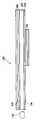
도 2는 도 1에 도시된 양방향 백라이트 어셈블리를 상세히 도시한 분해 사시도이다.FIG. 2 is an exploded perspective view illustrating in detail the bidirectional backlight assembly shown in FIG. 1.
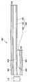
도 3은 도 2에 도시된 메인 몰드를 보다 상세히 도시한 사시도이다.3 is a perspective view illustrating the main mold shown in FIG. 2 in more detail.
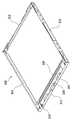
도 4는 도 2에 도시된 수납용기와 서브 몰드의 결합 관계를 설명하기 위한 도면이다.4 is a view for explaining the coupling relationship between the storage container and the sub-mold shown in FIG.
도 5는 도 4에 도시된 서브 몰드를 보다 상세히 도시한 사시도이다.FIG. 5 is a perspective view illustrating the sub mold shown in FIG. 4 in more detail.
도 6은 도 2에 도시된 양방향 백라이트 어셈블리의 빛샘 현상을 설명하기 위한 도면이다.FIG. 6 is a diagram for describing a light leakage phenomenon of the bidirectional backlight assembly illustrated in FIG. 2.
도 7은 도 6의 D-D 선을 절단한 단면도이다.FIG. 7 is a cross-sectional view taken along line D-D of FIG. 6.
도 8은 본 발명의 다른 실시예에 따른 양방향 백라이트 어셈블리를 설명하기 위한 개념도이다.8 is a conceptual diagram illustrating a bidirectional backlight assembly according to another embodiment of the present invention.
도 9는 도 8에 도시된 양방향 백라이트 어셈블리를 상세히 도시한 분해 사시도이다.FIG. 9 is an exploded perspective view illustrating in detail the bidirectional backlight assembly shown in FIG. 8.
도 10은 본 발명의 일 실시예에 따른 양방향 액정표시장치를 도시한 분해 사시도이다.10 is an exploded perspective view illustrating a bidirectional liquid crystal display according to an exemplary embodiment of the present invention.
도 11은 도 10에 도시된 액정표시패널 어셈블리를 상세히 설명하기 위한 도면이다.FIG. 11 is a view for explaining the liquid crystal display panel assembly shown in FIG. 10 in detail.
<도면의 주요 부분에 대한 부호의 설명><Explanation of symbols for the main parts of the drawings>
100 : 양방향 백라이트 어셈블리 110 : 광원100: bidirectional backlight assembly 110: light source
120 : 도광판 130 : 반사/투과 시트120: light guide plate 130: reflective / transparent sheet
140 : 제1 광학시트류 150 : 제2 광학시트류140: first optical sheet 150: second optical sheet
210 : 메인 몰드 220 : 수납용기210: main mold 220: storage container
230 : 서브 몰드 610 : 메인 액정표시패널 어셈블리230: sub mold 610: main liquid crystal display panel assembly
620 : 서브 액정표시패널 어셈블리620: sub liquid crystal display panel assembly
본 발명은 양방향 백라이트 어셈블리 및 이를 이용한 양방향 액정표시장치에 관한 것으로, 더욱 상세하게는 광원에서 발생한 광을 서로 다른 2개의 방향으로 공급하여 서로 다른 2개의 방향에서 정보를 디스플레이 할 수 있도록 한 양방향 백라이트 어셈블리 및 이를 이용한 양방향 액정표시장치에 관한 것이다.The present invention relates to a bidirectional backlight assembly and a bidirectional liquid crystal display device using the same. More particularly, the bidirectional backlight assembly is configured to display information in two different directions by supplying light generated from a light source in two different directions. And a bidirectional liquid crystal display using the same.
일반적으로 종래 액정표시장치는 전계의 세기에 따라서 광투과도가 변경되는 액정을 이용하여 디스플레이를 수행하는 장치로 정의할 수 있다. 이와 같은 액정표 시장치는 얇은 두께를 갖는 평판 타입의 표시장치로 구현할 수 있는 장점을 갖는다.In general, a conventional liquid crystal display device may be defined as a device for performing a display using a liquid crystal whose light transmittance is changed according to the intensity of an electric field. Such a liquid crystal display market has an advantage that it can be implemented as a flat panel type display device having a thin thickness.
이와 같은 장점을 갖는 액정표시장치는 휴대폰과 같은 통신 장치 및 휴대용 컴퓨터 또는 데스크탑용 컴퓨터의 디스플레이 장치로 폭넓게 사용되고 있다.The liquid crystal display device having such an advantage is widely used as a communication device such as a mobile phone and a display device of a portable computer or a desktop computer.
이와 같은 종래 액정표시장치는 일반적으로 한쪽 방향으로만 화상을 디스플레이하는 것이 일반적이었다.In such a conventional liquid crystal display device, it is common to display an image only in one direction.
최근에는 액정표시장치가 한쪽 방향으로만 화상을 디스플레이 하는 것에서 탈피하여 양쪽 방향으로 동일한 화상 또는 서로 다른 화상을 디스플레이 하기 위한 노력 및 기술 개발이 진행되고 있다.In recent years, efforts have been made to develop and display technologies for displaying the same image or different images in both directions, instead of displaying the image in only one direction.
양쪽 방향으로 화상을 디스플레이 하는 종래 액정표시장치는 메인 화면을 디스플레이하기 위한 메인 액정표시패널과, 상기 메인 액정표시패널에 광을 공급하는 메인 백라이트 어셈블리와, 서브 화면을 디스플레이하기 위한 서브 액정표시패널, 및 상기 서브 액정표시패널에 광을 공급하기 위한 서브 백라이트 어셈블리를 구성 요소로 갖는다.Conventional liquid crystal display devices for displaying images in both directions include a main liquid crystal display panel for displaying a main screen, a main backlight assembly for supplying light to the main liquid crystal display panel, a sub liquid crystal display panel for displaying a sub screen, And a sub backlight assembly for supplying light to the sub liquid crystal display panel.
또한, 상기 메인 백라이트 어셈블리와 상기 서브 백라이트 어셈블리는 광을 발생하는 광원과, 상기 광의 경로를 변경시키기 위한 도광판과, 상기 광을 반사시키기 위한 반사판, 및 이들을 수납하기 위한 수납용기를 별도로 구비한다.The main backlight assembly and the sub backlight assembly may include a light source for generating light, a light guide plate for changing the path of the light, a reflector for reflecting the light, and a storage container for storing the light.
이와 같은 구성을 갖는 양쪽 방향으로 화상을 디스플레이 하는 종래 액정표시장치는 상기 메인 백라이트 어셈블리와 상기 서브 백라이트 어셈블리가 각각 하나의 모듈로 제작된 후, 상기 두 개의 백라이트 어셈블리를 결합하는 방식에 의해 양쪽 방향으로 별도의 광을 공급한다.In the conventional liquid crystal display for displaying images in both directions having the above configuration, the main backlight assembly and the sub backlight assembly are each made of one module, and then the two backlight assemblies are combined in both directions. Supply extra light.
그러나, 이와 같은 종래 액정표시장치는 별도로 모듈화된 두 개의 백라이트 어셈블리를 사용함으로써, 전체 백라이트 어셈블리의 두께가 두꺼워지는 문제점과 두 개의 광원을 구동하기 위해 소비 전력이 증가되는 문제점이 있다. 또한, 광원, 도광판, 반사판, 및 수납용기 등의 재료가 이중으로 소모되어 제조 원가가 증가되는 문제점이 있다.However, such a conventional liquid crystal display device has a problem in that the thickness of the entire backlight assembly is thickened and power consumption is increased to drive two light sources by using two separate backlight assemblies. In addition, a material such as a light source, a light guide plate, a reflecting plate, and a storage container is consumed in duplicate, thereby increasing manufacturing costs.
따라서, 본 발명은 이와 같은 종래 문제점을 감안한 것으로써, 본 발명의 목적은 하나의 광원을 이용하여 서로 다른 2개의 방향으로 광을 공급할 수 있는 양방향 백라이트 어셈블리를 제공하는 것이다.Accordingly, the present invention has been made in view of such a conventional problem, and an object of the present invention is to provide a bidirectional backlight assembly capable of supplying light in two different directions using one light source.
본 발명의 다른 목적은 하나의 광원에서 발생한 광을 서로 다른 2개의 방향으로 공급하여 서로 다른 2개의 방향에서 정보를 디스플레이 할 수 있는 양방향 액정표시장치를 제공하는 것이다.Another object of the present invention is to provide a bidirectional liquid crystal display device which can display information in two different directions by supplying light generated from one light source in two different directions.
상술한 본 발명의 목적을 달성하기 위한 양방향 백라이트 어셈블리는 광을 발생하는 광원, 도광판, 상기 광원과 상기 도광판을 수납하는 메인 몰드, 광량 제어 시트, 수납용기 및 서브 몰드를 포함한다.The bidirectional backlight assembly for achieving the above object of the present invention includes a light source for generating light, a light guide plate, a main mold for receiving the light source and the light guide plate, a light amount control sheet, a storage container, and a sub mold.
상기 도광판은 상기 광원으로부터 입사된 광을 제1 출사면과 상기 제1 출사면과 반대되는 제2 출사면으로 출사하고, 상기 광량 제어 시트는 상기 도광판의 상기 제2 출사면 상에 실장되어 상기 제2 출사면에서 출사되는 광의 일부는 반사하고 일부는 투과하는 역할을 수행한다.The light guide plate is configured to emit light incident from the light source to a first emission surface and a second emission surface opposite to the first emission surface, and the light amount control sheet is mounted on the second emission surface of the light guide plate, 2 A part of the light emitted from the exit surface reflects and a part transmits.
상기 수납용기는 상기 광량 제어 시트를 고정하기 위해 상기 메인 몰드와 결합되며, 바닥면 중 일부에는 광을 통과시키기 위한 개구부가 형성된다.The storage container is coupled to the main mold to fix the light quantity control sheet, and an opening part is formed at a part of the bottom surface to allow light to pass therethrough.
상기 서브 몰드는 상기 수납용기의 상기 개구부와 동일한 크기를 가지며, 상기 수납용기의 배면에 결합된다. 이때, 상기 서브 몰드는 광의 반사를 방지하기 위해 무광택의 검정색 재질로 이루어진다.The sub mold has the same size as the opening of the storage container and is coupled to the rear surface of the storage container. At this time, the sub-mold is made of a matte black material to prevent the reflection of light.
또한, 상기 양방향 백라이트 어셈블리는 상기 도광판의 제1 출사면 상에 실장되어 광의 휘도 특성을 향상시키는 제1 광학시트류와, 상기 수납용기의 상기 개구부 상에 배치되며 상기 서브 몰드에 의해 고정되는 제2 광학시트류를 더 포함한다.The bidirectional backlight assembly may include a first optical sheet mounted on a first exit surface of the light guide plate to improve a brightness characteristic of light, and a second optical sheet disposed on the opening of the storage container and fixed by the sub mold. It further includes optical sheets.
본 발명의 다른 목적을 달성하기 위한 양방향 액정표시장치는 메인 백라이트, 서브 백라이트, 메인 액정표시패널 어셈블리 및 서브 액정표시패널 어셈블리를 구비한다.A bidirectional liquid crystal display device for achieving another object of the present invention includes a main backlight, a sub backlight, a main liquid crystal display panel assembly and a sub liquid crystal display panel assembly.
상기 메인 백라이트는 광을 발생하는 광원과, 상기 광원으로부터 입사된 광을 제1 방향과 상기 제1 방향과 반대되는 제2 방향으로 출사하는 도광부 및 상기 광원과 상기 도광부를 수납하는 메인 몰드를 포함한다.The main backlight includes a light source for generating light, a light guide part for emitting light incident from the light source in a first direction and a second direction opposite to the first direction, and a main mold accommodating the light source and the light guide part. do.
상기 서브 백라이트는 상기 메인 백라이트의 제2 방향 측에 설치되어 상기 도광부의 상기 제2 방향으로 출사되는 광의 휘도 특성을 향상시키기 위한 제1 광학시트류와 상기 제1 광학시트류를 고정하는 서브 몰드를 포함한다.The sub backlight may be provided on the second direction side of the main backlight to fix the first optical sheets and the sub mold fixing the first optical sheets to improve the luminance characteristics of the light emitted in the second direction of the light guide part. Include.
상기 메인 액정표시패널 어셈블리는 상기 메인 백라이트의 상기 제1 방향 측 에 실장되어 상기 메인 백라이트로부터 출사되는 광을 이용하여 화면을 디스플레이하며, 상기 서브 액정표시패널 어셈블리는 상기 서브 백라이트의 상기 제2 방향 측에 실장되어 상기 서브 백라이트로부터 출사되는 광을 이용하여 화면을 디스플레이한다.The main liquid crystal display panel assembly is mounted on the first direction side of the main backlight to display a screen using light emitted from the main backlight, and the sub liquid crystal display panel assembly is the second direction side of the sub backlight. The screen is displayed by using the light emitted from the sub backlight.
이러한 양방향 백라이트 어셈블리 및 이를 이용한 양방향 액정표시장치에 따르면, 하나의 광원을 이용하여 서로 다른 2개의 방향으로 광을 공급함으로써, 백라이트 어셈블리의 두께를 줄이고 소비 전력을 감소시킬 수 있다. 또한, 서브 몰드를 검정색으로 구성함으로써, 서브 백라이트의 에지 부분에서 발생하는 빛샘 현상을 제거할 수 있다.According to the bidirectional backlight assembly and the bidirectional liquid crystal display using the same, light is supplied in two different directions using one light source, thereby reducing the thickness of the backlight assembly and power consumption. In addition, by configuring the sub mold in black, light leakage phenomenon occurring at the edge portion of the sub backlight can be eliminated.
이하, 첨부한 도면들을 참조하여, 본 발명의 바람직한 실시예들을 보다 상세하게 설명하고자 한다.Hereinafter, exemplary embodiments of the present invention will be described in detail with reference to the accompanying drawings.
도 1은 본 발명의 일 실시예에 따른 양방향 백라이트 어셈블리를 설명하기 위한 개념도이다.1 is a conceptual diagram illustrating a bidirectional backlight assembly according to an embodiment of the present invention.
도 1을 참조하면, 본 발명의 일 실시예에 따른 양방향 백라이트 어셈블리(100)는 광을 발생하는 광원(110), 광의 경로를 변경하기 위한 도광판(120), 반사/투과 시트(130), 제1 광학시트류(140) 및 제2 광학시트류(150)를 구비한다.Referring to FIG. 1, the
구체적으로, 광원(110)으로부터 발생한 광을 입사받은 도광판(120)은 제1 출사면(122)과, 제1 출사면(122)의 반대측에 위치한 제2 출사면(124)을 통해 양방향으로 광을 출사한다. 이와 같이 도광판(120)은 광원(110)으로부터 출사되는 점광원 또는 선광원 상태의 광을 면광원 상태의 광으로 변경하여 양방향으로 출사하는 역할을 수행한다.Specifically, the
도광판(120)의 제2 출사면(124) 상에는 전면적에 걸쳐 반사/투과 시트(130)가 배치된다. 반사/투과 시트(130)는 도광판(120)의 제2 출사면(124)으로 출사되는 광 중에서 일부는 반사시키고, 나머지 일부는 투과시키는 역할을 수행한다.The reflection /
이러한 반사/투과 시트(130)는 일 실시예로 폴리에틸렌 텔레프탈레이트 레진(polyethylene terephthalate resin ,PET) 물질을 발포 처리한 두께가 얇은 시트 또는 시트보다 후박한 플레이트 형상으로 제작할 수 있다. 이때, 반사/투과 시트(130)의 발포 처리 정도 또는 두께를 조절함으로써, 도광판(120)의 제1 출사면(122) 방향으로 출사되는 광량과 제2 출사면(124) 방향으로 출사되는 광량의 비율을 조절할 수 있다.In one embodiment, the reflective /
본 발명에서는 바람직한 일 실시예로 폴리에틸렌 텔레프탈레이트 레진 (PET)물질을 발포 처리하여 사용하였지만, 이외에도 광의 일부를 반사하고 나머지는 투과시키는 다른 물질로 제작하여도 무방하다.In the present invention, a polyethylene terephthalate resin (PET) material is used by foaming as a preferred embodiment, but may be made of another material that reflects a part of light and transmits the rest.
한편, 도광판(120)의 제1 출사면(122) 상에는 제1 광학시트류(140)가 배치되고, 반사/투과 시트(130) 상에는 제2 광학시트류(150)가 배치된다. 제1 광학시트류(140)는 도광판(120)의 제1 출사면(122)으로부터 출사되는 광의 휘도 특성을 향상시키기 위해, 광을 확산하는 확산 시트와 광을 집광하는 적어도 1매의 프리즘 시트로 구성된다. 제2 광학시트류(150)는 도광판(120)의 제2 출사면(124)으로부터 출사된 광 중에서 반사/투과 시트(130)를 투과한 광의 휘도 특성을 향상시키 기 위해 확산판과 적어도 1매의 프리즘 시트로 구성된다.Meanwhile, first
한편, 제2 광학시트류(150)는 반사/투과 시트(130)의 전면적에 걸쳐 배치될 수 있으나, 사용자가 원하는 크기와 원하는 위치에 따라 얼마든지 변화가 가능하며, 일반적으로 반사/투과 시트(130)보다는 작은 크리를 가지면서 중앙부 소정 위치에 배치된다.On the other hand, the second
이러한 구성을 갖는 본 발명의 일 실시예에 따른 양방향 백라이트 어셈블리(100)는 하나의 광원(110)과 하나의 도광판(120) 및 반사/투과 시트(130)를 이용하여 서로 다른 2개의 방향으로 광을 출사한다.
도 2는 도 1에 도시된 양방향 백라이트 어셈블리를 상세히 도시한 분해 사시도이다.FIG. 2 is an exploded perspective view illustrating in detail the bidirectional backlight assembly shown in FIG. 1.
도 2를 참조하면, 양방향 백라이트 어셈블리(100)는 광원(110)과 도광판(120)을 수납하기 위한 메인 몰드(210)와, 도광판(120)과 반사/투과 시트(130)를 메인 몰드(210)에 고정하기 위한 수납용기(220), 및 제2 광학시트류(150)를 고정하기 위한 서브 몰드(230)를 더 구비한다.Referring to FIG. 2, the
구체적으로, 도광판(120)과 반사/투과 시트(130)는 차례로 메인 몰드(210)에 실장된다. 이후 도광판(120)과 반사/투과 시트(130)를 고정하기 위해 메인 몰드(210)는 수납용기(220)와 체결된다. 또한, 메인 몰드(210)에는 광원(110)을 수납하기 위한 별도의 수납공간이 마련되어 있으며, 상기 수납공간에 광원(110)을 실장한 후 광원(110)에 구동 전원을 인가하기 위한 연성 인쇄회로기판(240)을 실장한다.Specifically, the
이때, 광원(110)으로는 적어도 하나의 발광 다이오드(Light Emitting Diode) 또는 냉음극 형광램프(Cold Cathode Fluorescence Lamp)가 사용되며, 연성 인쇄회로기판(240)은 일정 접점을 통해 광원(110)과 연결되어 외부로부터 공급되는 구동 전원을 상기 접점을 통해 광원(110)에 인가한다.In this case, at least one light emitting diode or a cold cathode fluorescent lamp is used as the
수납용기(220)의 바닥면(222) 상에는 반사/투과 시트(130)를 투과한 광을 출사하기 위한 개구부(224)가 형성된다. 또한, 수납용기(220)의 외측면 상에는 개구부(224)와 대응하는 위치에 제2 광학시트류(150)가 배치되며, 제2 광학시트류(150)를 고정하기 위한 서브 몰드(230)가 수납용기(220)의 개구부(224)에 체결된다.An
이와 같은 구성을 갖는 본 발명의 일 실시예에 따른 양방향 백라이트 어셈블리(100)는 메인 몰드(210)에 수납된 도광판(120)의 제1 출사면(122)을 통해 출사되어 제1 광학시트류(140)를 통과하여 출사되는 제1 방향의 광과, 도광판(120)의 제2 출사면(124)을 통해 출사되어 반사/투과 시트(130)를 투과한 광 중에서 수납용기(220)의 개구부(224)를 통해 출사되는 제2 방향의 광으로 이루어진 서로 다른 방향의 2개의 광을 공급한다.
도 3은 도 2에 도시된 메인 몰드를 보다 상세히 도시한 사시도이다.3 is a perspective view illustrating the main mold shown in FIG. 2 in more detail.
도 3을 참조하면, 메인 몰드(210)는 제1 내지 제4 측벽(211, 212, 213, 214)을 갖는 형태로 이루어지고, 그 중 제1 측벽(211)에는 광원(110)과 연성 인쇄회로기판(240)을 수납하기 위한 광원 수납공간을 갖는다. 또한, 제1 측벽(211)에 대향하는 제2 측벽(212)과, 제1 측벽(211)과 제2 측벽(212)을 연결하는 제3 측벽(213)의 높이는 제1 측벽(211)이나 제4 측벽(214)의 높이보다는 높게 형성되어, 제1 광 학시트류(140)의 수납을 원활하게 한다.Referring to FIG. 3, the
그러면, 상기한 메인 몰드(210)의 제1 측벽(211)에 대해서 보다 상세히 설명한다.Next, the
제1 측벽(211)은 매설부(216), 돌출부재(217), 요입부(218) 및 격벽(219)으로 이루어진다.The
보다 상세하게는, 매설부(216)는 제1 측벽(211)의 높이를 일정 단차만큼 차감한 높이로 형성되는데, 바람직하게는 연성 인쇄회로기판(240)과 연결된 신호라인을 통과시키기에 적당한 높이로 형성된다. 여기서, 매설부(216)를 경유하는 신호라인은 외부로부터 제공되는 구동 전원을 연성 인쇄회로기판(240)에 제공하며, 구동 전원을 제공받은 연성 인쇄회로기판(240)은 일정 접점을 통해 연결된 광원(110)에 발광을 위한 일정 전원을 제공한다.More specifically, the buried
돌출부재(217)는 메인 몰드(210)의 내측을 향하도록 돌출 형성되어, 상부에 배치되는 연성 인쇄회로기판(240)을 지지하고, 측부에는 광원(110)을 격납한다. 이때 돌출되는 길이는 도광판(120)에 접하는 광원(110)의 길이와 동일한 것이 바람직하다.The protruding
요입부(218)는 제1 측벽(211)으로부터 돌출된 돌출부재(217)를 제외한 나머지 공간에 형성되어, 광원(110), 바람직하게는 복수의 발광 다이오드를 수납한다.The
격벽(219)은 상기한 돌출부재(217)와 일정 간격만큼 이격되고, 제1 측벽(211)의 형성 방향과 평행하게 형성되어 상부에 배치되는 연성 인쇄회로기판(240)을 지지하며, 하부에 배치되는 도광판(120)을 고정한다.The
이러한 구성을 갖는 메인 몰드(210)는 제1 내지 제4 측벽(211, 212, 213, 214)에 형성된 걸림턱을 통해 수납용기(220)와 체결된다.The
도 4는 도 2에 도시된 수납용기와 서브 몰드의 결합 관계를 설명하기 위한 도면이며, 도 5는 도 4에 도시된 서브 몰드를 보다 상세히 도시한 사시도이다.FIG. 4 is a view for explaining a coupling relationship between the storage container and the sub mold illustrated in FIG. 2, and FIG. 5 is a perspective view illustrating the sub mold illustrated in FIG. 4 in more detail.
도 4 및 도 5를 참조하면, 수납용기(220)의 바닥면(222) 상에는 광을 출사하기 위한 개구부(224)가 형성되며, 개구부(224)의 네 면에는 서브 몰드(230)와의 체결을 위한 돌출부(226)가 각각 형성된다. 또한 수납용기(220)의 네 측면에는 메인 몰드(210)와의 결합을 위한 결합부재(228)가 형성된다.4 and 5, an
이러한 형상을 갖는 수납용기(220)는 결합부재(228)에 형성된 홈이 메인 몰드(210)의 제1 내지 제4 측벽(211, 212, 213, 214)에 형성된 걸림턱과 결합되는 방식에 의해 메인 몰드(210)와 체결된다.The
한편, 제2 광학시트류(150)는 수납용기(220)의 개구부(224)와 같은 면적을 갖도록 형성되어 개구부(224)와 대응되는 위치에 실장된다. 여기서, 제2 광학시트류(150)는 수납용기(220)의 개구부(224)를 통해 출사되는 제2 방향의 광의 특성을 향상시키기 위해 확산 시트와 적어도 1매의 프리즘 시트를 포함한다.On the other hand, the second
구체적으로, 상기 확산 시트는 도광판(120)의 제2 출사면(124)에서 출사되어 반사/투과 시트(130)를 투과한 광 중에서 수납용기(220)의 개구부(224)를 통해 출사되는 광을 산란시켜 보다 균일한 휘도 분포를 갖도록 한다.Specifically, the diffusion sheet is a light emitted from the
상기 프리즘 시트는 적어도 1매가 일 실시예로 상기 확산 시트의 상면에 설치되어 상기 확산 시트로부터 출사된 광의 방향성을 보정하여 시야각을 개선하는 역할을 수행한다.At least one prism sheet is installed on an upper surface of the diffusion sheet in one embodiment, and serves to improve the viewing angle by correcting the direction of light emitted from the diffusion sheet.
이와 같은 제2 광학시트류(150)를 고정하기 위해 서브 몰드(230)는 수납용기(220)와 체결된다.In order to fix the second
서브 몰드(230)는 제5 내지 제8 측벽(231, 233, 235, 237)으로 이루어진 사각 프레임 형상을 가지며, 제5 내지 제8 측벽(231, 233, 235, 237) 외측면에는 각각 수납용기(220)의 개구부(224)에 형성된 돌출부(226)와 결합하기 위한 결합홈(232)이 형성된다.The
구체적으로, 결합홈(232)은 제5 내지 제8 측벽(231, 233, 235, 237) 외측면으로부터 내측으로 일정 거리만큼 들어가는 형태로 형성된다. 따라서, 제2 광학시트류(150)를 수납용기(220)의 개구부(224) 상에 실장한 후, 상기한 서브 몰드(230)의 결합홈(232)에 수납용기(220)의 돌출부(226)를 끼워 넣는 방식에 의해 제2 광학시트류(150)와 서브 몰드(230)를 수납용기(220)에 고정한다.Specifically, the
또한, 서브 몰드(230)의 제5 내지 제8 측벽(231, 233, 235, 237) 내측면에는 제2 광학시트류(150)의 이탈을 방지하고, 서브 영상을 디스플레이하기 위한 서브 액정표시패널 어셈블리(미도시)의 실장을 가이드하기 위한 고정부재(234)가 더 형성된다.In addition, a sub liquid crystal display panel for preventing separation of the second
그러나, 이와 같은 구성을 갖는 본 발명의 일 실시예에 따른 양방향 백라이트 어셈블리(100)는 제1 방향으로 광이 출사되는 면적에 비해 제2 방향으로 광이 출사되는 면적이 작을 경우, 제2 방향의 광이 출사되는 서브 몰드(230)의 모서리 부분이 다른 부분보다 밝게 보이는 빛샘 현상이 발생할 수 있다.However, in the
도 6은 도 2에 도시된 양방향 백라이트 어셈블리의 빛샘 현상을 설명하기 위한 도면이며, 도 7은 도 6의 D-D 선을 절단한 단면도로써, 빛샘 현상을 제거하기 위한 일 예를 보여주기 위한 도면이다.FIG. 6 is a diagram illustrating a light leakage phenomenon of the bidirectional backlight assembly illustrated in FIG. 2, and FIG. 7 is a cross-sectional view taken along line D-D of FIG. 6, and illustrates an example for removing the light leakage phenomenon.
도 6 및 도 7을 참조하면, 서브 몰드(230)는 제2 방향의 광을 출사하기 위해 수납용기(220)의 전체 면적 중에서 중앙 부분의 일정 영역만 차지하도록 설치된다. 이런 경우, 광원(110)에서 발생하여 도광판(120)으로 입사된 광 중에서, 도광판(120)의 제2 출사면(124)으로 출사되는 광은 반사/투과 시트(130)를 투과한 후, 서브 몰드(230)가 위치한 영역에 한정하여 출사된다.6 and 7, the
이때, 서브 몰드(230)가 흰색이나 광택이 나는 재질로 이루어진 경우, 광원(110)과 대향하는 위치에 배치된 서브 몰드(230)의 제5 측벽(231)에 인접한 A 영역과, 제5 측벽(232)과 접하는 제6 측벽(233)에 인접한 B 영역, 및 제6 측벽(233)과 대향하는 제7 측벽에 인접한 C 영역에서는 출사되는 광이 서브 몰드(230)의 내측면에 반사되어 다른 영역보다 밝게 보이는 빛샘 현상이 발생한다.In this case, when the
따라서, 본 발명의 일 실시예에 따른 서브 몰드(230)는 상기한 빛샘 현상을 제거하기 위해, 서브 몰드(230)의 재질을 무광택의 검정색 재질로 구성하여 서브 몰드(230)의 내측면에서 일어나는 반사를 차단하는 것이 바람직하다.Accordingly, in order to remove the light leakage phenomenon, the
또한, 서브 몰드(230)의 네 측벽이 위치하는 영역에 검정 테이프(240)를 붙여 빛이 새는 것을 차단하는 것도 가능하다.In addition, the
구체적으로, 검정 테이프(240)는 반사/투과 시트(130)와 서브 몰드(230)의 네 측벽(231, 233, 235, 237)이 접하는 부분에 개재되어 설치된다. 이러한 검정 테 이프(240)는 반사/투과 시트(130)를 통해 출사되는 제2 방향의 광 중에서 서브 몰드(230)의 측벽으로 향하는 광을 차단함으로써, 서브 몰드(230)의 모서리 부분에서 발생하는 빛샘 현상을 제거할 수 있다.Specifically, the
이상과 같이 본 발명의 일 실시예에 따른 양방향 백라이트 어셈블리(100)는 하나의 광원(110)과 하나의 도광판(120)을 이용하여 서로 다른 2 개의 방향으로 광을 공급할 수 있으며, 또한, 서브 몰드(230)의 재질을 무광택의 검정색 재질로 사용하여 빛샘 현상을 제거할 수 있다.As described above, the
도 8은 본 발명의 다른 실시예에 따른 양방향 백라이트 어셈블리를 설명하기 위한 개념도이다. 본 실시예에서 도광판과 반사/투과 시트를 제외한 나머지 구성은 일 실시예와 동일함으로 그 중복된 설명은 생략하기로 하며, 일 실시예와 동일한 부분에 대해서는 동일한 도면 부호 및 명칭을 사용하기로 한다.8 is a conceptual diagram illustrating a bidirectional backlight assembly according to another embodiment of the present invention. Except for the light guide plate and the reflection / transmission sheet in this embodiment, the rest of the configuration is the same as in the exemplary embodiment, and the duplicate description thereof will be omitted, and the same reference numerals and names will be used for the same parts as the exemplary embodiment.
도 8을 참조하면, 본 발명의 다른 실시예에 따른 백라이트 어셈블리(400)는 광을 발생하는 광원(110)과, 광의 경로를 변경하기 위한 도광부(440)와, 제1 광학시트류(140), 및 제2 광학 시트류(150)를 구비한다.Referring to FIG. 8, the
도광부(440)는 다시 제1 도광판(410)과, 제2 도광판(420), 및 상기 제1 도광판(410)과 제2 도광판(420) 사이에 배치되는 반사판(430)을 포함한다.The
구체적으로, 하나의 광원(110)으로부터 발생한 광 중에서 일부는 제1 도광판(410)으로 입사되고, 나머지 일부는 제2 도광판(420)으로 입사된다. 광원(110)으로부터 광을 입사 받은 제1 도광판(410)은 제1 광학시트류(140)와 접하는 광출사면(412)과, 이에 대향하여 반사판(430)과 접하는 광반사면(414)을 가지 며, 제2 도광판(420) 또한 제2 광학시트류(150)와 접하는 광출사면(422)과, 이에 대향하여 반사판(430)과 접하는 광반사면(424)을 갖는다.Specifically, some of the light generated from one
광원(110)으로부터 제1 도광판(410)으로 입사된 대부분의 광은 광출사면(412)으로 직접 출사되거나 또는 반사판(430)에 반사되는 과정을 통해 광출사면(412)으로 출사된다. 이와 마찬가지로, 광원(110)으로부터 제2 도광판(420)으로 입사된 대부분의 광은 제2 도광판(420)의 광출사면(422)으로 직접 출사되거나 또는 반사판(430)에 반사되는 과정을 통해 광출사면(422)으로 출사된다.Most of the light incident from the
한편, 제2 도광판(420)은 제1 도광판(410)과 같은 크기를 가질 수 있으나, 사용자가 원하는 크기에 따라 얼마든지 변화가 가능하며, 바람직하게는, 제1 도광판(410)보다는 작은 크기를 가지면서 광이 입사되는 측면이 나란히 위치할 수 있도록 배치된다.Meanwhile, the
이러한 구성을 갖는 본 발명의 다른 실시예에 따른 양방향 백라이트 어셈블리(400)는 하나의 광원(110)과 두 개의 도광판(410, 420) 및 반사판(430)를 이용하여 서로 다른 2개의 방향으로 광을 출사한다.The
도 9는 도 8에 도시된 양방향 백라이트 어셈블리를 상세히 도시한 분해 사시도이다.FIG. 9 is an exploded perspective view illustrating in detail the bidirectional backlight assembly shown in FIG. 8.
도 9를 참조하면, 본 발명의 다른 실시예에 따른 양방향 백라이트 어셈블리(400)는 광을 발생하는 광원(110)과, 광을 양방향으로 출사하기 위한 도광부(440)와, 광원(110)과 도광부(440)를 수납하기 위한 메인 몰드(210)와, 수납용기(220), 및 서브 몰드(230)를 포함한다.9, a
도광부(440)는 다시 제1 도광판(410)과, 제2 도광판(420), 및 제1 도광판(410)과 제2 도광판(420) 사이에 개재되는 반사판(430)을 포함한다.The
구체적으로, 광원(110)으로부터 발생한 광은 제1 도광판(410)과 제2 도광판(420)으로 나누어져 입사된다. 이때, 제1 도광판(410)과 제2 도광판(420)의 사이에는 반사판(430)이 설치되어, 제1 도광판(410)의 광반사면(414)으로 출사되는 광을 제1 도광판(410)의 광출사면(412)으로 반사시키며, 제2 도광판(420)의 광반사면(424)으로 출사되는 광을 제2 도광판(420)의 광출사면(422)으로 반사시키는 역할을 수행한다. 이러한 반사판(430)의 역할에 의해, 제1 도광판(410)은 광출사면(412)으로만 제1 방향의 광을 출사하며, 제2 도광판(420)은 광출사면(422)으로만 제1 방향의 반대인 제2 방향의 광을 출사한다.Specifically, the light generated from the
이러한 구성을 갖는 도광부(440)는 메인 몰드(210)와 수납용기(220)의 체결에 의해 수납된다.The
한편, 수납용기(220)의 바닥면(222) 상에는 제2 도광판(420)의 위치와 대응하여 개구부(224)가 형성된다. 이러한 개구부(224)는 제2 도광판(420)의 광출사면(422)을 통해 출사되는 광을 통과시키기 위해 형성되며, 바람직하게는, 광원(110)으로부터 발생한 광이 제2 도광판(420)으로 바로 입사될 수 있도록 광원(110)과 인접한 위치에 형성된다.On the other hand, the
수납용기(220)의 개구부(224)에 결합되는 서브 몰드(230)는 상술한 일 실시예와 마찬가지로, 서브 몰드(230)의 모서리 부분에서 발생할 수 있는 빛샘 현상을 제거하기 위해 무광택의 검정색 재질로 이루어지는 것이 바람직하다. 또한, 서브 몰드(230)의 측벽과 제2 도광판(420) 사이에 검정 테이프를 개재하여 빛이 새는 현상을 제거할 수 있다.The
이와 같은 구성을 갖는 본 발명의 다양한 실시예에 의한 양방향 백라이트 어셈블리에는 액정표시패널 어셈블리가 결합되어 양방향 액정표시장치를 이룬다. 이하, 양방향 액정표시장치의 구성요소인 양방향 백라이트 어셈블리는 앞서 상세하게 설명하였음으로, 그 중복된 설명은 생략하기로 한다. 또한, 앞서 양방향 백라이트 어셈블리를 설명하는 과정에서 사용되었던 용어 및 도면부호는 그대로 사용하기로 한다.The bidirectional backlight assembly according to various embodiments of the present invention having such a configuration forms a bidirectional liquid crystal display by combining a liquid crystal display panel assembly. Hereinafter, since the bidirectional backlight assembly, which is a component of the bidirectional liquid crystal display, has been described in detail above, a duplicate description thereof will be omitted. In addition, terms and reference numerals used in the above description of the bidirectional backlight assembly will be used as they are.
도 10은 본 발명의 일 실시예에 따른 양방향 액정표시장치를 도시한 분해 사시도이다.10 is an exploded perspective view illustrating a bidirectional liquid crystal display according to an exemplary embodiment of the present invention.
도 10을 참조하면, 본 발명의 일 실시예에 따른 양방향 액정표시장치(600)는 메인 액정표시패널 어셈블리(610), 서브 액정표시패널 어셈블리(620) 및 앞서 도 2에서 설명된 양방향 백라이트 어셈블리(100)를 포함한다.Referring to FIG. 10, the bidirectional liquid
양방향 백라이트 어셈블리(100)는 다시 메인 백라이트(630)와 서브 백라이트(640)로 구분될 수 있다.The
구체적으로, 메인 액정표시패널 어셈블리(610)는 메인 백라이트(630)에 실장된다. 이러한 메인 액정표시패널 어셈블리(610)는 도광판(120)의 제1 출사면(122)에서 출사되어 제1 광학시트류(140)를 통과한 제1 방향의 광을 공급받아 정보가 포함된 메인 화면을 디스플레이한다.In detail, the main liquid crystal
한편, 서브 액정표시패널 어셈블리(620)는 서브 백라이트(640)에 실장된다. 이러한 서브 액정표시패널 어셈블리(640)는 도광판(120)의 제2 출사면(124)에서 출사되어 반사/투과 시트(130)를 투과한 후 제2 광학시트류(150)를 통과한 제2 방향의 광을 공급받아 정보가 포함된 서브 화면을 디스플레이한다.The sub liquid
이때, 메인 액정표시패널 어셈블리(610)의 디스플레이 면적과 서브 액정표시패널 어셈블리(620)의 디스플레이 면적은 동일하게 설정될 수 있으나, 도 10에 도시된 바와 같이 메인 액정표시패널 어셈블리(610)의 디스플레이 면적 및 서브 액정표시패널 어셈블리(620)의 디스플레이 면적을 서로 다르게 구성할 수도 있다.In this case, the display area of the main liquid
본 발명에서는 일 실시예로 메인 액정표시패널 어셈블리(610)의 디스플레이 면적이 서브 액정표시패널 어셈블리(620)의 디스플레이 면적보다 크게 설정된다.In an exemplary embodiment, the display area of the main liquid
이처럼 서브 액정표시패널 어셈블리(620)의 디스플레이 면적이 메인 액정표시패널 어셈블리(610)의 디스플레이 면적보다 작을 경우, 앞서 설명한 양방향 백라이트 어셈블리(100)의 일 실시예에서와 같이 서브 몰드(230)의 모서리 부분에서 발생하는 빛샘 현상에 의해 부분적으로 화면이 밝게 보이는 현상이 발생할 수 있다.As such, when the display area of the sub liquid
따라서, 앞서 설명한 양방향 백라이트 어셈블리(100)와 같이, 서브 몰드(230)의 재질을 광택이 나지 않는 검정색의 재질을 사용하거나, 또는 서브 몰드(230)의 측벽과 반사/투과 시트(130) 사이에 검정색 테이프를 붙이는 방식으로 상기한 빛샘 현상을 제거할 수 있다.Accordingly, as in the
한편, 양방향 액정표시장치(600)는 메인 액정표시패널 어셈블리(610)가 메인 백라이트(630)로부터 이탈되는 것을 방지하기 위한 메인 샤시(650)와 서브 액정표시패널 어셈블리(620)가 서브 백라이트(640)로부터 이탈되는 것을 방지하기 위한 서브 샤시(660)를 더 포함한다.Meanwhile, in the bidirectional
도 11은 도 10에 도시된 액정표시패널 어셈블리를 상세히 설명하기 위한 도면이다. 여기서, 메인 액정표시패널 어셈블리(610)와 서브 액정표시패널 어셈블리(620)는 동일한 구성을 가지므로, 서브 액정표시패널 어셈블리(620)에 대한 설명은 생략한다.FIG. 11 is a view for explaining the liquid crystal display panel assembly shown in FIG. 10 in detail. Here, since the main liquid crystal
도 11을 참조하면, 메인 액정표시패널 어셈블리(610)는 액정표시패널(614), 구동칩(616) 및 연성 회로부(618)로 구성된다.Referring to FIG. 11, the main liquid crystal
액정표시패널(614)은 다시 제1 기판(611), 상기 제1 기판(611)과 마주보는 제2 기판(612) 및 상기 제1 기판(611)과 제2 기판(612)의 사이에 개재된 액정층(미도시)을 포함한다.The liquid
구체적으로, 제2 기판(612)에는 다수의 화소가 매트릭스 형태로 구비되고, 상기 다수의 화소 각각은 제1 방향으로 연장된 게이트 라인 및 상기 제1 방향과 직교하는 제2 방향으로 연장되어 상기 게이트 라인과 절연되어 교차하는 데이터 라인을 구비한다. 또한, 상기 각 화소에는 박막 트랜지스터(Thin Film Transistor; 이하, TFT)가 형성되어 상기 게이트 라인 및 데이터 라인에 연결된다.In detail, the
제2 기판(612)의 일측에는 상기 데이터 라인 및 상기 게이트 라인에 구동신호를 인가하기 위한 구동칩(616)이 실장된다. 이러한 구동칩(616)은 데이터 라인용 칩과 게이트 라인용 칩으로 분리된 두 개 이상의 칩으로 구성되거나, 이들을 통합한 하나의 칩으로 구성될 수 있으며, COG(Chip On Glass) 공정에 의하여 상기 제2 기판(612)의 일측에 실장된다.On one side of the
또한, 구동칩(616)이 실장된 제2 기판(612)의 일측에는 상기 구동칩(616)을 제어하기 위한 제어신호를 인가하기 위해 연성 회로부(618)가 더 부착된다. 이러한 연성 회로부(618)는 구동신호의 타이밍을 조절하기 위한 타이밍 컨트롤러나 데이터 신호를 저장하기 위한 메모리 등이 실장되며, 이방성 도전필름을 매개로 제2 기판(612)과 전기적으로 연결된다.In addition, a
이와 같은 구성을 갖는 본 발명의 일 실시예에 따른 양방향 액정표시장치(600)는 하나의 광원(110)과, 하나의 도광판(120), 및 반사/투과 시트(130)를 이용하여 양방향으로 광을 공급하는 양방향 백라이트 어셈블리(100)를 이용하여 메인 액정표시패널 어셈블리(610)와 서브 액정표시패널 어셈블리(620)를 통해 양방향으로 화면을 디스플레이한다.The bidirectional
이와 같은 양방향 백라이트 어셈블리 및 이를 이용한 양방향 액정표시장치에 따르면, 하나의 광원만을 이용하여 서로 다른 두 개의 방향으로 광을 공급함으로써, 백라이트 어셈블리의 두께를 줄이고 소비전력을 감소시킬 수 있다.According to such a bidirectional backlight assembly and a bidirectional liquid crystal display using the same, by supplying light in two different directions using only one light source, the thickness of the backlight assembly can be reduced and power consumption can be reduced.
또한, 메인 디스플레이 면적과 서브 디스플레이 면적이 다를 경우, 서브 몰드의 재질을 광의 반사가 일어나지 않는 검정색 재질로 구성함으로써, 빛샘 현상을 제거할 수 있다.In addition, when the main display area and the sub display area are different, the light leakage phenomenon may be removed by configuring the material of the sub mold with a black material which does not reflect light.
앞서 설명한 본 발명의 상세한 설명에서는 본 발명의 바람직한 실시예를 참조하여 설명하였지만, 해당 기술분야의 숙련된 당업자 또는 해당 기술분야에 통상의 지식을 갖는 자라면 후술될 특허청구범위에 기재된 본 발명의 사상 및 기술 영 역으로부터 벗어나지 않는 범위 내에서 본 발명을 다양하게 수정 및 변경시킬 수 있음을 이해할 수 있을 것이다.In the detailed description of the present invention described above with reference to a preferred embodiment of the present invention, those skilled in the art or those skilled in the art having ordinary knowledge in the scope of the invention described in the claims to be described later It will be understood that various modifications and variations can be made in the present invention without departing from the scope of the present invention.
Claims (17)
Translated fromKoreanPriority Applications (5)
| Application Number | Priority Date | Filing Date | Title |
|---|---|---|---|
| KR1020030042007AKR100953424B1 (en) | 2003-06-26 | 2003-06-26 | Bidirectional backlight assembly and bidirectional liquid crystal display using the same |
| US10/679,400US7001059B2 (en) | 2003-06-26 | 2003-10-07 | Two-way backlight assembly and two-way liquid crystal display apparatus having the same |
| US11/326,197US7290918B2 (en) | 2003-06-26 | 2006-01-05 | Two-way backlight assembly and two-way liquid crystal display apparatus having the same |
| US11/926,651US7527417B2 (en) | 2003-06-26 | 2007-10-29 | Two-way backlight assembly and two-way liquid crystal display apparatus having the same |
| US12/411,440US7922381B2 (en) | 2003-06-26 | 2009-03-26 | Two-way backlight assembly and two-way liquid crystal display apparatus having the same |
Applications Claiming Priority (1)
| Application Number | Priority Date | Filing Date | Title |
|---|---|---|---|
| KR1020030042007AKR100953424B1 (en) | 2003-06-26 | 2003-06-26 | Bidirectional backlight assembly and bidirectional liquid crystal display using the same |
Publications (2)
| Publication Number | Publication Date |
|---|---|
| KR20050001726A KR20050001726A (en) | 2005-01-07 |
| KR100953424B1true KR100953424B1 (en) | 2010-04-19 |
Family
ID=36567199
Family Applications (1)
| Application Number | Title | Priority Date | Filing Date |
|---|---|---|---|
| KR1020030042007AExpired - Fee RelatedKR100953424B1 (en) | 2003-06-26 | 2003-06-26 | Bidirectional backlight assembly and bidirectional liquid crystal display using the same |
Country Status (2)
| Country | Link |
|---|---|
| US (4) | US7001059B2 (en) |
| KR (1) | KR100953424B1 (en) |
Cited By (1)
| Publication number | Priority date | Publication date | Assignee | Title |
|---|---|---|---|---|
| US8773614B2 (en) | 2011-01-03 | 2014-07-08 | Lg Display Co., Ltd. | Two-way liquid crystal display device |
Families Citing this family (65)
| Publication number | Priority date | Publication date | Assignee | Title |
|---|---|---|---|---|
| KR100887635B1 (en)* | 2002-09-26 | 2009-03-11 | 삼성전자주식회사 | Backlight Assembly and Liquid Crystal Display Using Same |
| TWI227768B (en)* | 2002-10-29 | 2005-02-11 | Fujitsu Display Tech | Illumination device and liquid crystal display device using the same |
| KR100953424B1 (en)* | 2003-06-26 | 2010-04-19 | 삼성전자주식회사 | Bidirectional backlight assembly and bidirectional liquid crystal display using the same |
| KR101016564B1 (en)* | 2003-08-01 | 2011-02-22 | 삼성전자주식회사 | Bidirectional backlight assembly and bidirectional liquid crystal display using the same |
| JP4079143B2 (en)* | 2003-12-22 | 2008-04-23 | セイコーエプソン株式会社 | LIGHTING DEVICE, ELECTRO-OPTICAL DEVICE, AND ELECTRONIC DEVICE |
| JP2005243346A (en)* | 2004-02-25 | 2005-09-08 | Citizen Electronics Co Ltd | Double-side light-emitting lighting device |
| KR101001457B1 (en)* | 2004-04-23 | 2010-12-14 | 엘지디스플레이 주식회사 | LCD Display |
| JP4055741B2 (en)* | 2004-05-24 | 2008-03-05 | セイコーエプソン株式会社 | Electro-optical device and electronic apparatus |
| KR100961074B1 (en)* | 2004-05-31 | 2010-06-08 | 엘지디스플레이 주식회사 | LCD Display |
| JP4238806B2 (en)* | 2004-09-21 | 2009-03-18 | セイコーエプソン株式会社 | Light guide plate, lighting device, electro-optical device, and electronic device |
| KR20060034528A (en)* | 2004-10-19 | 2006-04-24 | 삼성전자주식회사 | Display device that can adjust the height of display panel |
| KR101082904B1 (en)* | 2004-10-25 | 2011-11-11 | 삼성전자주식회사 | Light guide panel, and back light assembly and display device having the same |
| US7165865B2 (en)* | 2004-12-03 | 2007-01-23 | Arima Display Corporation | Folding mobile phone and double-sided liquid crystal display panel |
| US7322732B2 (en)* | 2004-12-23 | 2008-01-29 | Cree, Inc. | Light emitting diode arrays for direct backlighting of liquid crystal displays |
| US20060139297A1 (en)* | 2004-12-29 | 2006-06-29 | Esa-Sakari Maatta | Display for mobile phone |
| KR20060086174A (en)* | 2005-01-26 | 2006-07-31 | 삼성전자주식회사 | Integrated liquid crystal display |
| CN100376971C (en)* | 2005-03-03 | 2008-03-26 | 友达光电股份有限公司 | Backlight module and liquid crystal display device |
| JP2007206546A (en)* | 2006-02-03 | 2007-08-16 | Citizen Electronics Co Ltd | Backlight |
| JP2007225788A (en)* | 2006-02-22 | 2007-09-06 | Citizen Electronics Co Ltd | Light guide plate, front and rear integrally formed backlight using light guide plate and liquid crystal display device using backlight |
| US7637648B2 (en)* | 2006-02-28 | 2009-12-29 | Samsung Mobile Display Co., Ltd. | Portable display device |
| KR101272256B1 (en)* | 2006-03-20 | 2013-06-13 | 삼성디스플레이 주식회사 | Container Member, Manufacturing Method of Container Member and Flat Panel Display Using the Same |
| WO2007139781A2 (en)* | 2006-05-23 | 2007-12-06 | Cree Led Lighting Solutions, Inc. | Lighting device |
| KR100968340B1 (en)* | 2006-06-30 | 2010-07-08 | 엘지디스플레이 주식회사 | LCD and portable computer having same |
| US7759882B2 (en)* | 2006-07-31 | 2010-07-20 | Microsemi Corp.—Analog Mixed Signal Group Ltd. | Color control for scanning backlight |
| KR100785025B1 (en)* | 2006-10-26 | 2007-12-12 | 삼성전자주식회사 | Double-sided lighting device for display device and double-sided display device using the same |
| US20080136770A1 (en)* | 2006-12-07 | 2008-06-12 | Microsemi Corp. - Analog Mixed Signal Group Ltd. | Thermal Control for LED Backlight |
| US7548030B2 (en)* | 2007-03-29 | 2009-06-16 | Microsemi Corp.—Analog Mixed Signal Group Ltd. | Color control for dynamic scanning backlight |
| US20080297691A1 (en)* | 2007-05-29 | 2008-12-04 | Shawn Kim | Back light unit and liquid crystal display with the same |
| US7812297B2 (en)* | 2007-06-26 | 2010-10-12 | Microsemi Corp. - Analog Mixed Signal Group, Ltd. | Integrated synchronized optical sampling and control element |
| US8562770B2 (en) | 2008-05-21 | 2013-10-22 | Manufacturing Resources International, Inc. | Frame seal methods for LCD |
| KR200466526Y1 (en)* | 2007-11-30 | 2013-04-24 | 엘지디스플레이 주식회사 | Display device |
| US8408775B1 (en)* | 2008-03-12 | 2013-04-02 | Fusion Optix, Inc. | Light recycling directional control element and light emitting device using the same |
| WO2009113055A2 (en)* | 2008-03-13 | 2009-09-17 | Microsemi Corp. - Analog Mixed Signal Group, Ltd. | A color controller for a luminaire |
| TWI398686B (en)* | 2008-03-26 | 2013-06-11 | Au Optronics Corp | Dual display module |
| TWI413951B (en)* | 2008-05-20 | 2013-11-01 | Lextar Electronics Corp | Image display apparatus |
| US9573346B2 (en) | 2008-05-21 | 2017-02-21 | Manufacturing Resources International, Inc. | Photoinitiated optical adhesive and method for using same |
| TW201004477A (en)* | 2008-06-10 | 2010-01-16 | Microsemi Corp Analog Mixed Si | Color manager for backlight systems operative at multiple current levels |
| BRPI1008027A2 (en)* | 2009-02-10 | 2016-03-15 | Sharp Kk | liquid crystal display device |
| US8529111B2 (en)* | 2009-02-12 | 2013-09-10 | Nai-Chien Chang | Notebook computer having dual display screens |
| US8324830B2 (en)* | 2009-02-19 | 2012-12-04 | Microsemi Corp.—Analog Mixed Signal Group Ltd. | Color management for field-sequential LCD display |
| US8764264B2 (en) | 2011-10-11 | 2014-07-01 | GE Lighting Solutions, LLC | Edge-lit luminaire |
| US9881528B2 (en) | 2011-10-13 | 2018-01-30 | Manufacturing Resources International, Inc. | Transparent liquid crystal display on display case |
| JP6189588B2 (en)* | 2012-09-03 | 2017-08-30 | Necプラットフォームズ株式会社 | Liquid crystal display device and manufacturing method thereof |
| KR101882827B1 (en) | 2012-11-02 | 2018-07-30 | 삼성디스플레이 주식회사 | LIQUID CRYSTAL display |
| CN103287651B (en)* | 2013-05-31 | 2015-11-25 | 深圳市华星光电技术有限公司 | A kind of pallet of display panel assembly |
| JP2015227987A (en)* | 2014-06-02 | 2015-12-17 | 株式会社ジャパンディスプレイ | Liquid crystal display device |
| JP6425425B2 (en)* | 2014-06-10 | 2018-11-21 | 三菱電機株式会社 | Display device |
| US9500801B2 (en) | 2014-06-16 | 2016-11-22 | Manufacturing Resources International, Inc. | LED assembly for transparent liquid crystal display |
| US9535293B2 (en) | 2014-06-16 | 2017-01-03 | Manufacturing Resources International, Inc. | Sealed transparent liquid crystal display assembly |
| EP3550547B1 (en)* | 2014-06-16 | 2023-01-11 | Manufacturing Resources International, Inc. | Transparent lcd assembly with display case |
| US9526352B2 (en) | 2014-06-16 | 2016-12-27 | Manufacturing Resources International, Inc. | Wireless video transmission system for liquid crystal display |
| US9633366B2 (en) | 2014-06-16 | 2017-04-25 | Manufacturing Resources International, Inc. | System for tracking and analyzing display case usage |
| US9500896B2 (en) | 2014-06-16 | 2016-11-22 | Manufacturing Resources International, Inc. | Cooling system for liquid crystal display |
| US9436037B2 (en)* | 2014-06-20 | 2016-09-06 | Shenzhen China Star Optoelectronics Technology Co., Ltd | Double-sides liquid crystal devices and backlight modules |
| TWI557474B (en)* | 2014-09-16 | 2016-11-11 | 友達光電股份有限公司 | Double-layered backlight module |
| US10649273B2 (en) | 2014-10-08 | 2020-05-12 | Manufacturing Resources International, Inc. | LED assembly for transparent liquid crystal display and static graphic |
| US9832847B2 (en) | 2014-10-09 | 2017-11-28 | Manufacturing Resources International, Inc. | System for decreasing energy usage of a transparent LCD display case |
| US10182665B2 (en) | 2014-10-15 | 2019-01-22 | Manufacturing Resources International, Inc. | System and method for preventing damage to products |
| JP2019513251A (en) | 2016-03-02 | 2019-05-23 | マニュファクチャリング・リソーシズ・インターナショナル・インコーポレーテッド | Vending machine with transparent display |
| WO2018009399A1 (en) | 2016-07-08 | 2018-01-11 | Manufacturing Resources International, Inc. | Mirror having an integrated electronic display |
| CN205880454U (en)* | 2016-08-04 | 2017-01-11 | 扬升照明股份有限公司 | Backlight module and display device |
| TWI686634B (en)* | 2019-07-11 | 2020-03-01 | 友達光電股份有限公司 | Display device |
| WO2022174006A1 (en) | 2021-02-12 | 2022-08-18 | Manufacturing Resourcesinternational, Inc | Display assembly using structural adhesive |
| CN113514976A (en)* | 2021-04-28 | 2021-10-19 | 武汉华星光电技术有限公司 | Vehicle-mounted display panel and vehicle device |
| US12350730B1 (en) | 2023-12-27 | 2025-07-08 | Manufacturing Resources International, Inc. | Bending mandril comprising ultra high molecular weight material, related bending machines, systems, and methods |
Citations (3)
| Publication number | Priority date | Publication date | Assignee | Title |
|---|---|---|---|---|
| JPH1152140A (en)* | 1997-08-07 | 1999-02-26 | Enplas Corp | Side light type surface light source device |
| KR20010035369A (en)* | 2001-02-07 | 2001-05-07 | 박종섭 | device for backright of dual polder handyphone |
| KR20030045888A (en)* | 2001-12-03 | 2003-06-12 | 주식회사 팬택 | Dual way display type liquid crystal display device |
Family Cites Families (9)
| Publication number | Priority date | Publication date | Assignee | Title |
|---|---|---|---|---|
| JPH0670882B2 (en)* | 1988-08-23 | 1994-09-07 | 株式会社明拓システム | Edge light panel using single plate |
| JP3714735B2 (en)* | 1996-08-26 | 2005-11-09 | シャープ株式会社 | Display element holding frame and display device using the same |
| US6925313B2 (en)* | 2001-02-07 | 2005-08-02 | Hyundai Curitel Inc. | Folder-type mobile communication terminal having double-sided LCD |
| JP3901503B2 (en)* | 2001-07-30 | 2007-04-04 | 株式会社東芝 | Liquid crystal display device and manufacturing method thereof |
| JP3599022B2 (en)* | 2002-01-10 | 2004-12-08 | カシオ計算機株式会社 | Liquid crystal display |
| JP4323219B2 (en)* | 2002-05-31 | 2009-09-02 | 三星モバイルディスプレイ株式會社 | Surface light source device and liquid crystal display element assembly using the same |
| JP2004021238A (en)* | 2002-06-20 | 2004-01-22 | Nec Saitama Ltd | Display device and mobile terminal system |
| TWI308239B (en)* | 2002-10-25 | 2009-04-01 | Toppoly Optoelectronics Corp | Light module and flat panel display including the light module |
| KR100953424B1 (en)* | 2003-06-26 | 2010-04-19 | 삼성전자주식회사 | Bidirectional backlight assembly and bidirectional liquid crystal display using the same |
- 2003
- 2003-06-26KRKR1020030042007Apatent/KR100953424B1/ennot_activeExpired - Fee Related
- 2003-10-07USUS10/679,400patent/US7001059B2/ennot_activeExpired - Fee Related
- 2006
- 2006-01-05USUS11/326,197patent/US7290918B2/ennot_activeExpired - Fee Related
- 2007
- 2007-10-29USUS11/926,651patent/US7527417B2/ennot_activeExpired - Fee Related
- 2009
- 2009-03-26USUS12/411,440patent/US7922381B2/ennot_activeExpired - Fee Related
Patent Citations (3)
| Publication number | Priority date | Publication date | Assignee | Title |
|---|---|---|---|---|
| JPH1152140A (en)* | 1997-08-07 | 1999-02-26 | Enplas Corp | Side light type surface light source device |
| KR20010035369A (en)* | 2001-02-07 | 2001-05-07 | 박종섭 | device for backright of dual polder handyphone |
| KR20030045888A (en)* | 2001-12-03 | 2003-06-12 | 주식회사 팬택 | Dual way display type liquid crystal display device |
Cited By (1)
| Publication number | Priority date | Publication date | Assignee | Title |
|---|---|---|---|---|
| US8773614B2 (en) | 2011-01-03 | 2014-07-08 | Lg Display Co., Ltd. | Two-way liquid crystal display device |
Also Published As
| Publication number | Publication date |
|---|---|
| KR20050001726A (en) | 2005-01-07 |
| US7527417B2 (en) | 2009-05-05 |
| US20040264211A1 (en) | 2004-12-30 |
| US20060114692A1 (en) | 2006-06-01 |
| US7922381B2 (en) | 2011-04-12 |
| US20080049169A1 (en) | 2008-02-28 |
| US20090185103A1 (en) | 2009-07-23 |
| US7001059B2 (en) | 2006-02-21 |
| US7290918B2 (en) | 2007-11-06 |
Similar Documents
| Publication | Publication Date | Title |
|---|---|---|
| KR100953424B1 (en) | Bidirectional backlight assembly and bidirectional liquid crystal display using the same | |
| JP4520116B2 (en) | Backlight assembly and liquid crystal display device having the same | |
| US7139048B2 (en) | Backlight assembly and liquid crystal display apparatus comprising a light guide plate having light source receiving recess and light guiding recess | |
| KR101232045B1 (en) | Back light assembly and liquid crystal display apparatus having the same | |
| US20100053506A1 (en) | Liquid crystal display using the same | |
| US20080297698A1 (en) | Light illuminating unit and liquid crystal display device having the same | |
| WO2012057017A1 (en) | Lighting device and display device | |
| KR101016564B1 (en) | Bidirectional backlight assembly and bidirectional liquid crystal display using the same | |
| KR20050030723A (en) | Back light assembly and liquid crystal display having the same | |
| KR20050030724A (en) | Back light assembly and liquid crystal display having the same | |
| KR100887633B1 (en) | LCD Display | |
| KR20060059476A (en) | Back light assembly and liquid crystal display device having same | |
| KR20050049196A (en) | Back light assembly and liquid crystal display having the same | |
| KR101075598B1 (en) | Display device | |
| KR100948620B1 (en) | Interactive LCD | |
| KR20070044312A (en) | Interactive LCD | |
| KR20050097791A (en) | Display apparatus | |
| KR20050005865A (en) | Two-way back light assembly and two-way liquid crystal display device using the same | |
| KR20060094196A (en) | Back light assembly and display device having same | |
| KR20060019217A (en) | LCD Display | |
| KR20060134741A (en) | LCD Display | |
| KR20060012195A (en) | LCD Display | |
| KR20060110652A (en) | Back light assembly and display device having same | |
| KR20060019215A (en) | Back light assembly and liquid crystal display device having the same | |
| KR20060005865A (en) | Display |
Legal Events
| Date | Code | Title | Description |
|---|---|---|---|
| PA0109 | Patent application | St.27 status event code:A-0-1-A10-A12-nap-PA0109 | |
| R18-X000 | Changes to party contact information recorded | St.27 status event code:A-3-3-R10-R18-oth-X000 | |
| PG1501 | Laying open of application | St.27 status event code:A-1-1-Q10-Q12-nap-PG1501 | |
| PN2301 | Change of applicant | St.27 status event code:A-3-3-R10-R13-asn-PN2301 St.27 status event code:A-3-3-R10-R11-asn-PN2301 | |
| PN2301 | Change of applicant | St.27 status event code:A-3-3-R10-R13-asn-PN2301 St.27 status event code:A-3-3-R10-R11-asn-PN2301 | |
| A201 | Request for examination | ||
| PA0201 | Request for examination | St.27 status event code:A-1-2-D10-D11-exm-PA0201 | |
| E902 | Notification of reason for refusal | ||
| PE0902 | Notice of grounds for rejection | St.27 status event code:A-1-2-D10-D21-exm-PE0902 | |
| E13-X000 | Pre-grant limitation requested | St.27 status event code:A-2-3-E10-E13-lim-X000 | |
| P11-X000 | Amendment of application requested | St.27 status event code:A-2-2-P10-P11-nap-X000 | |
| P13-X000 | Application amended | St.27 status event code:A-2-2-P10-P13-nap-X000 | |
| E701 | Decision to grant or registration of patent right | ||
| PE0701 | Decision of registration | St.27 status event code:A-1-2-D10-D22-exm-PE0701 | |
| GRNT | Written decision to grant | ||
| PR0701 | Registration of establishment | St.27 status event code:A-2-4-F10-F11-exm-PR0701 | |
| PR1002 | Payment of registration fee | St.27 status event code:A-2-2-U10-U11-oth-PR1002 Fee payment year number:1 | |
| PG1601 | Publication of registration | St.27 status event code:A-4-4-Q10-Q13-nap-PG1601 | |
| R18-X000 | Changes to party contact information recorded | St.27 status event code:A-5-5-R10-R18-oth-X000 | |
| PN2301 | Change of applicant | St.27 status event code:A-5-5-R10-R11-asn-PN2301 | |
| PN2301 | Change of applicant | St.27 status event code:A-5-5-R10-R11-asn-PN2301 | |
| PN2301 | Change of applicant | St.27 status event code:A-5-5-R10-R14-asn-PN2301 | |
| FPAY | Annual fee payment | Payment date:20130329 Year of fee payment:4 | |
| PR1001 | Payment of annual fee | St.27 status event code:A-4-4-U10-U11-oth-PR1001 Fee payment year number:4 | |
| FPAY | Annual fee payment | Payment date:20140401 Year of fee payment:5 | |
| PR1001 | Payment of annual fee | St.27 status event code:A-4-4-U10-U11-oth-PR1001 Fee payment year number:5 | |
| FPAY | Annual fee payment | Payment date:20150417 Year of fee payment:6 | |
| PR1001 | Payment of annual fee | St.27 status event code:A-4-4-U10-U11-oth-PR1001 Fee payment year number:6 | |
| R18-X000 | Changes to party contact information recorded | St.27 status event code:A-5-5-R10-R18-oth-X000 | |
| LAPS | Lapse due to unpaid annual fee | ||
| PC1903 | Unpaid annual fee | St.27 status event code:A-4-4-U10-U13-oth-PC1903 Not in force date:20160410 Payment event data comment text:Termination Category : DEFAULT_OF_REGISTRATION_FEE | |
| PC1903 | Unpaid annual fee | St.27 status event code:N-4-6-H10-H13-oth-PC1903 Ip right cessation event data comment text:Termination Category : DEFAULT_OF_REGISTRATION_FEE Not in force date:20160410 |