KR100950990B1 - Bone Therapy - Google Patents
Bone TherapyDownload PDFInfo
- Publication number
- KR100950990B1 KR100950990B1KR1020080089358AKR20080089358AKR100950990B1KR 100950990 B1KR100950990 B1KR 100950990B1KR 1020080089358 AKR1020080089358 AKR 1020080089358AKR 20080089358 AKR20080089358 AKR 20080089358AKR 100950990 B1KR100950990 B1KR 100950990B1
- Authority
- KR
- South Korea
- Prior art keywords
- tool
- bone
- conduit
- guide
- head
- Prior art date
- Legal status (The legal status is an assumption and is not a legal conclusion. Google has not performed a legal analysis and makes no representation as to the accuracy of the status listed.)
- Active
Links
- 210000000988bone and boneAnatomy0.000titleclaimsabstractdescription115
- 238000002560therapeutic procedureMethods0.000titleclaimsdescription6
- 238000000034methodMethods0.000claimsabstractdescription45
- 230000008878couplingEffects0.000claimsabstractdescription38
- 238000010168coupling processMethods0.000claimsabstractdescription38
- 238000005859coupling reactionMethods0.000claimsabstractdescription38
- 125000006850spacer groupChemical group0.000claimsabstractdescription30
- 238000003780insertionMethods0.000claimsabstractdescription18
- 230000037431insertionEffects0.000claimsabstractdescription18
- 210000002615epidermisAnatomy0.000claimsabstractdescription7
- 229910000831SteelInorganic materials0.000claimsdescription53
- 239000010959steelSubstances0.000claimsdescription53
- 239000000463materialSubstances0.000claimsdescription28
- 239000000945fillerSubstances0.000claimsdescription26
- 238000007920subcutaneous administrationMethods0.000claimsdescription2
- 230000001939inductive effectEffects0.000claims2
- 230000001225therapeutic effectEffects0.000claims2
- 230000002093peripheral effectEffects0.000claims1
- 238000001356surgical procedureMethods0.000abstractdescription6
- 230000035876healingEffects0.000abstract1
- 229920005989resinPolymers0.000description29
- 239000011347resinSubstances0.000description29
- 239000004743PolypropyleneSubstances0.000description10
- DHKHKXVYLBGOIT-UHFFFAOYSA-Nacetaldehyde Diethyl AcetalNatural productsCCOC(C)OCCDHKHKXVYLBGOIT-UHFFFAOYSA-N0.000description10
- 125000002777acetyl groupChemical class[H]C([H])([H])C(*)=O0.000description10
- -1polypropylenePolymers0.000description10
- 229920001155polypropylenePolymers0.000description10
- 230000010339dilationEffects0.000description8
- 239000005020polyethylene terephthalateSubstances0.000description8
- 229920000139polyethylene terephthalatePolymers0.000description8
- 239000004677NylonSubstances0.000description5
- 229920000122acrylonitrile butadiene styrenePolymers0.000description5
- 239000004568cementSubstances0.000description5
- 229920005669high impact polystyrenePolymers0.000description5
- 239000004797high-impact polystyreneSubstances0.000description5
- 229920001778nylonPolymers0.000description5
- 239000004417polycarbonateSubstances0.000description5
- 229920000515polycarbonatePolymers0.000description5
- 229920013716polyethylene resinPolymers0.000description5
- 229910001220stainless steelInorganic materials0.000description5
- RTAQQCXQSZGOHL-UHFFFAOYSA-NTitaniumChemical compound[Ti]RTAQQCXQSZGOHL-UHFFFAOYSA-N0.000description4
- 239000002639bone cementSubstances0.000description4
- 238000000926separation methodMethods0.000description4
- 239000010935stainless steelSubstances0.000description4
- 229910052719titaniumInorganic materials0.000description3
- 239000010936titaniumSubstances0.000description3
- 241001631457CannulaSpecies0.000description1
- 208000020339Spinal injuryDiseases0.000description1
- 230000004308accommodationEffects0.000description1
- 229910052782aluminiumInorganic materials0.000description1
- XAGFODPZIPBFFR-UHFFFAOYSA-NaluminiumChemical compound[Al]XAGFODPZIPBFFR-UHFFFAOYSA-N0.000description1
- 239000000316bone substituteSubstances0.000description1
- 230000006835compressionEffects0.000description1
- 238000007906compressionMethods0.000description1
- 238000010276constructionMethods0.000description1
- 230000007423decreaseEffects0.000description1
- 230000000694effectsEffects0.000description1
- 229920006015heat resistant resinPolymers0.000description1
- 239000007788liquidSubstances0.000description1
- 238000010297mechanical methods and processMethods0.000description1
- 239000000203mixtureSubstances0.000description1
- 206010033675panniculitisDiseases0.000description1
- 238000000053physical methodMethods0.000description1
- 238000011084recoveryMethods0.000description1
- 239000000523sampleSubstances0.000description1
- 238000004904shorteningMethods0.000description1
- 210000003491skinAnatomy0.000description1
- 206010041569spinal fractureDiseases0.000description1
- 230000000087stabilizing effectEffects0.000description1
- 210000004304subcutaneous tissueAnatomy0.000description1
Images


Classifications
- A—HUMAN NECESSITIES
- A61—MEDICAL OR VETERINARY SCIENCE; HYGIENE
- A61B—DIAGNOSIS; SURGERY; IDENTIFICATION
- A61B17/00—Surgical instruments, devices or methods
- A61B17/34—Trocars; Puncturing needles
- A—HUMAN NECESSITIES
- A61—MEDICAL OR VETERINARY SCIENCE; HYGIENE
- A61B—DIAGNOSIS; SURGERY; IDENTIFICATION
- A61B17/00—Surgical instruments, devices or methods
- A61B17/34—Trocars; Puncturing needles
- A61B17/3472—Trocars; Puncturing needles for bones, e.g. intraosseus injections
- A—HUMAN NECESSITIES
- A61—MEDICAL OR VETERINARY SCIENCE; HYGIENE
- A61B—DIAGNOSIS; SURGERY; IDENTIFICATION
- A61B17/00—Surgical instruments, devices or methods
- A61B17/56—Surgical instruments or methods for treatment of bones or joints; Devices specially adapted therefor
- A61B17/58—Surgical instruments or methods for treatment of bones or joints; Devices specially adapted therefor for osteosynthesis, e.g. bone plates, screws or setting implements
- A61B17/88—Osteosynthesis instruments; Methods or means for implanting or extracting internal or external fixation devices
- A61B17/8802—Equipment for handling bone cement or other fluid fillers
- A61B17/8805—Equipment for handling bone cement or other fluid fillers for introducing fluid filler into bone or extracting it
- A61B17/8819—Equipment for handling bone cement or other fluid fillers for introducing fluid filler into bone or extracting it characterised by the introducer proximal part, e.g. cannula handle, or by parts which are inserted inside each other, e.g. stylet and cannula
- A—HUMAN NECESSITIES
- A61—MEDICAL OR VETERINARY SCIENCE; HYGIENE
- A61M—DEVICES FOR INTRODUCING MEDIA INTO, OR ONTO, THE BODY; DEVICES FOR TRANSDUCING BODY MEDIA OR FOR TAKING MEDIA FROM THE BODY; DEVICES FOR PRODUCING OR ENDING SLEEP OR STUPOR
- A61M25/00—Catheters; Hollow probes
- A61M25/01—Introducing, guiding, advancing, emplacing or holding catheters
- A61M25/06—Body-piercing guide needles or the like
Landscapes
- Health & Medical Sciences (AREA)
- Life Sciences & Earth Sciences (AREA)
- Surgery (AREA)
- Animal Behavior & Ethology (AREA)
- General Health & Medical Sciences (AREA)
- Engineering & Computer Science (AREA)
- Biomedical Technology (AREA)
- Heart & Thoracic Surgery (AREA)
- Veterinary Medicine (AREA)
- Public Health (AREA)
- Orthopedic Medicine & Surgery (AREA)
- Medical Informatics (AREA)
- Molecular Biology (AREA)
- Nuclear Medicine, Radiotherapy & Molecular Imaging (AREA)
- Pathology (AREA)
- Biophysics (AREA)
- Pulmonology (AREA)
- Anesthesiology (AREA)
- Hematology (AREA)
- Surgical Instruments (AREA)
- Prostheses (AREA)
Abstract
Translated fromKoreanDescription
Translated fromKorean본 발명은 표피에서 뼈로의 통로를 제공하기 위한 뼈 치료용 장치에 관한 것으로, 특히 척추 골절을 치료하기 위한 외과적 수술방법의 하나인 척추굴절복원술(Kyphoplasty)에 사용되는 카테터 액세서리 도구를 포함하는 장치에 관한 것이다.The present invention relates to a device for treating bone for providing a passage from the epidermis to a bone, in particular a device comprising a catheter accessory tool used in Kyphoplasty, which is one of the surgical methods for treating spinal fractures. It is about.
척추굴절복원술이란 척추후만증에서 손상된 척추를 원래의 높이 및 각도로 회복시킨 후 뼈 충진 물질을 주입하여 안정화시키는 시술방법이다. 이 시술은 일반적으로 경피적으로 수행되며, 척추의 높이 및 각도의 회복은 현재 액체의 압력 또는 기계적인 방법에 의한 척추내 팽창에 의해 수행되고 있다.Spinal refraction surgery is a method of stabilizing spinal injuries by injecting bone filling material after restoring the vertebrae damaged at the original height and angle. This procedure is generally performed percutaneously, and the recovery of the height and angle of the spine is currently being performed by the pressure of the liquid or by intravertebral dilation by mechanical methods.
척추굴절복원술에 사용되는 장치에는 복원기와 액세서리 도구들이 있으며, 풍선 복원 시술의 경우 풍선 카테터 등의 공동형성도구(cavity-forming instrument)가 복원기와 함께 사용된다. 상기 액세서리 도구들 중 뼈로의 접근통로를 제공하기 위해 사용되는 도구는 통상 파이프와 강선으로 이루어지는 니들(Needle), 와이어핀(Wire-pin), 캐뉼러(Cannula)와 확장관(Expander)을 포함하여 이루어진다. 또한, 그 외에 스페이서(Spacer), 필러(Filler), 푸셔(Pusher) 등을 추가로 포함할 수 있다.Apparatuses used in spinal refraction surgery include restoring and accessory tools, and in the case of balloon restoring procedures, a cavity-forming instrument such as a balloon catheter is used with the restoring apparatus. Among the accessory tools, tools used to provide access to bones include needles, wire-pins, cannulas and expanders, which usually consist of pipes and steel wires. Is done. In addition, a spacer, a filler, a pusher, and the like may be further included.
종래의 풍선 복원 시술방법은, 예를 들어, 압박 굴절된 부위에 가늘고 긴 특수 튜브를 삽입하여 이를 통해 풍선을 넣어 정상적인 높이만큼 팽창시킨 후 풍선은 제거하고 뼈 충진물질(예: 골시멘트, 골 대체물질)로 벌어진 공간을 채워주는 순서로 진행될 수 있다.Conventional balloon restoration method, for example, by inserting a long elongated special tube into the compression refracted portion through the balloon inflated to a normal height, the balloon is removed and bone filling material (eg bone cement, bone replacement) It can proceed in order to fill the spaces of the material).
상기 방법을 상술하면, 먼저 선단부(시술시 기준)가 뾰쪽하게 형성된 니들로 인체 외부에서 시술부를 뚫고 척추 내부로 들어간 후 상기 니들의 구성품 중 파이프(Pipe) 안에서 강선을 빼낸다. 이후 와이어 핀을 니들의 파이프에 삽입한 후 니들의 파이프를 인체로부터 빼내어 분리시킨다. 이후 와이어 핀을 가이드로 하여 확장관과 캐뉼러를 차례로 인체 내에 삽입하여 공간을 넓힌 후 상기 확장관을 인체 외부로 분리한다. 이후 스페이서를 캐뉼러에 삽입하여 드릴 모양의 선단부로 주변부에 풍선 카테터 등의 공동형성도구가 원활하게 삽입될 수 있도록 내부 공간을 확보해준다. 이후 복원기에 풍선 카테터를 장착하여 풍선이 구비된 카테터의 선단부를 캐뉼러에 삽입하고, 복원기의 압력에 의해 척추 내부에서 풍선을 확장하게 된다. 이후, 뼈 충진물질이 주입된 복수의 필러(Filler, 1회적 사용)를 한번씩 반복적으로 캐뉼러에 삽입하고, 푸셔(Pusher)에 의해 도관 형태의 필러 내부를 뼈 쪽으로 밀어줌으로써, 척추 내에 확장된 공간 안으로 뼈 충진물질이 주입되는 단계로 수술과정이 일단락된다.When the method is described in detail, first, the tip portion (standard during the procedure) is penetrated into the spine through the treatment part from the outside of the human body with a needle having a sharp point, and then the wire is removed from the pipe among the components of the needle. After inserting the wire pin into the pipe of the needle and then remove the pipe of the needle from the human body. Thereafter, the extension tube and the cannula are inserted into the human body in turn using a wire pin as a guide, thereby widening the space, and then separating the extension tube to the outside of the human body. The spacer is then inserted into the cannula to secure the internal space so that the cavity-shaped catheter such as a balloon catheter can be inserted smoothly into the periphery of the drill shape. Thereafter, the balloon catheter is mounted on the decompressor to insert the tip of the catheter with the balloon into the cannula, and the balloon is expanded inside the spine by the pressure of the decompressor. Thereafter, a plurality of fillers (one-time use) into which the bone filling material is injected are repeatedly inserted into the cannula one by one, and the inside of the conduit-shaped filler is pushed toward the bone by a pusher, thereby expanding the space within the spine. The procedure is completed by the step of injecting bone filler into.
그러나 상기 배경기술의 외과적 시술 단계에 제공되는 기존의 카테터 액세서리 도구는 사용상에 있어서 여러 가지 문제점 및 불편한 요소들을 안고 있다.However, existing catheter accessory tools provided in the surgical procedure stage of the background suffer from various problems and inconveniences in use.
예를 들어, 시술자에 의해 피시술자(被施術者)의 피부를 통하여 삽입되는 니들은, 선단부가 뾰쪽하고 날카로운 형태로 연마된 탐침으로 구성되는 것이 일반적이고, 외과용 해머나 전동기구에 의하여 척추 뼈에 이르게 되는데, 이후 분리시에 뼈를 이루고 있는 무기질과 유기질 혼합물이 일종의 콘크리트와 같은 역할을 하여 뼈로부터 쉽게 분리되지 못하는 문제가 있다. 따라서 이를 해결하기 위해 별도의 분리장치가 마련되거나 해머 등의 물리적 방법에 의해 삽입시의 타격방향과 역방향으로 니들을 가격하는 등의 비정형적 방법 등이 실시되고 있으나, 이는 시술자에게 불편을 주고 시술의 완성도를 저하시킨다.For example, the needle inserted by the operator through the skin of the operator is generally composed of a probe whose tip is polished into a sharp and sharp shape, and is applied to the vertebral bone by a surgical hammer or a power tool. This leads to a problem in that the inorganic and organic mixture forming the bone at the time of separation acts like a kind of concrete and is not easily separated from the bone. Therefore, in order to solve this problem, a separate separation device is provided or atypical methods such as hitting the needle in the opposite direction to the hitting direction at the time of insertion by a physical method such as a hammer are performed. Decreases completeness.
또한, 와이어 핀을 가이드로 하여 확장관과 캐뉼러를 인체 내에 삽입한 후 확장관을 외부에서 조작하여 척추 내부를 확장하는 단계에서도, 확장관을 손쉽게 분리하거나 또는 캐뉼러에 안정적으로 고정할 수 있는 구조를 마련하지 못하여 많은 불편과 제약이 따르고 있는 실정이다.In addition, the extension tube and the cannula are inserted into the human body using the wire pin as a guide, and then, even in the step of expanding the inside of the spine by manipulating the extension tube from the outside, the extension tube can be easily removed or stably fixed to the cannula. There is a lot of inconvenience and constraints due to the lack of structure.
뿐만 아니라 기존의 척추 뼈 내부에 공간을 확보하기 위한 스페이서는 선단부를 드릴 날의 모양으로 구비하고 있으나, 이는 뼈 조직을 파고들어가면서 불필요한 절삭분을 발생시키고 작업의 효율성을 떨어뜨리는 문제점이 있다.In addition, the spacer for securing a space inside the existing vertebral bone is provided with a tip of a drill blade, but this has a problem of generating unnecessary cutting while digging into bone tissue and reducing work efficiency.
본 발명은 상기와 같은 문제점을 해결하기 위한 것으로서, 본 발명의 목적은, 확장관과 캐뉼러를 용이하게 결합 및 분리할 수 있는 뼈 치료용 장치를 제공하는데 있다.The present invention is to solve the above problems, it is an object of the present invention to provide a device for bone treatment that can be easily coupled and separated expansion tube and cannula.
본 발명의 다른 목적은, 니들 또는 니들 내의 강선을 뼈로부터 손쉽게 분리할 수 있는 뼈 치료용 장치를 제공하는데 있다.Another object of the present invention is to provide a device for bone treatment that can easily separate the needle or the wire in the needle from the bone.
본 발명의 또 다른 목적은, 불필요한 절삭의 발생을 방지하고, 뼈 속 내부에 공동형성도구의 삽입 공간을 보다 용이하게 확보할 수 있는 뼈 치료용 장치를 제공하는데 있다.Still another object of the present invention is to provide an apparatus for treating bone, which prevents unnecessary cutting and makes it possible to more easily secure an insertion space of the cavity-forming tool inside the bone.
또한 본 발명은 시술시의 문제만을 극복하는데에 그치지 아니하고, 인체공학적인 외형 구조를 포함하여 이를 통한 편의성을 도모하도록 하는 것에도 부가적인 목적이 있다.In addition, the present invention is not only to overcome the problems during the procedure, but also has an additional object to facilitate the convenience, including the ergonomic appearance structure.
상기 목적을 달성하기 위하여, 본 발명은 결합 구조가 개선된 확장관 및 캐뉼러를 포함하는 새로운 형태의 장치를 제공한다.In order to achieve the above object, the present invention provides a new type of device including an expansion tube and cannula with improved coupling structure.
또한, 본 발명은 구성요소의 결합 구조가 개선된 니들을 추가로 포함하는 장치를 제공한다.The present invention also provides an apparatus further comprising a needle with an improved coupling structure of the components.
또한, 본 발명은 나사부 형태가 개선된 스페이서를 추가로 포함하는 장치를 제공한다.The present invention also provides a device further comprising a spacer with improved thread form.
또한, 본 발명은 가이드, 필러, 푸셔 등의 다른 도구를 추가로 포함하는 장치를 제공한다.The present invention also provides an apparatus further comprising other tools such as guides, pillars, pushers and the like.
그 외에, 본 발명은 뼈로부터의 분리가 용이한 니들 도구를 포함하는 뼈 치료용 장치 및 불필요한 절삭분을 발생시키지 않는 개선된 구조의 스페이서 도구를 포함하는 뼈 치료용 장치를 제공한다.In addition, the present invention provides a device for treating bone, including a device for treating bone, including a needle tool that is easy to detach from the bone, and a device for treating bone, including a spacer tool of improved construction that does not generate unnecessary cutting.
이와 같은 본 발명의 뼈 치료용 장치에 의하면, 특히 경피적 풍선 척추굴절복원 시술에 있어서, 골시멘트 등의 뼈 충진물질을 채울 수 있도록 풍선 등에 의해 공간을 형성시키는 장치의 사용에 앞서, 뼈를 관통하여 접근 통로를 제공하고 뼈 내부에 공간을 확보하는 카테터 액세서리 도구의 기능적 동작을 보다 효과적으로 제공할 수 있다. 즉, 확장관을 캐뉼러에 안정적으로 고정하고, 이를 뼈 또는 캐뉼러로부터 손쉽게 분리할 수 있으며, 도킹가능한 구조의 확장관과 캐뉼러를 제공하여 시술과정을 간단화할 수 있다. 또한 니들을 뼈로부터 용이하게 분리할 수 있다. 또한, 스페이서 작업시 불필요한 절삭을 발생시키지 않아 작업의 효율을 높일 수 있으며, 뼈 속 내부에 공동형성도구가 원활히 삽입될 수 있는 공간을 보다 손쉽게 확보할 수 있다. 그 결과, 시술 시간을 단축시키고 시술의 완성도를 높일 수 있는 뛰어난 효과가 있다.According to such a device for bone treatment of the present invention, particularly in the percutaneous balloon spinal refraction restoration procedure, prior to the use of the device for forming a space by a balloon or the like to fill the bone filling material such as bone cement, It can more effectively provide the functional behavior of a catheter accessory tool that provides access passages and provides space inside the bone. That is, the expansion tube can be stably fixed to the cannula, and it can be easily separated from the bone or cannula, and the expansion tube and the cannula of the dockable structure can be provided to simplify the procedure. The needle can also be easily separated from the bone. In addition, it is possible to increase the efficiency of the work by not generating unnecessary cutting when working with the spacer, it is possible to more easily secure a space for the cavity forming tool can be inserted into the bone smoothly. As a result, there is an excellent effect that can shorten the procedure time and increase the completeness of the procedure.
본 발명은 표피에서 뼈로의 통로를 제공하기 위한 뼈 치료용 장치에 관한 것으로, 특히 척추굴절복원 시술에 응용될 수 있는 카테터 액세서리 도구를 포함하는 뼈 치료용 장치에 관한 것이다.The present invention relates to a device for treating bone for providing a passage from the epidermis to a bone, and more particularly to a device for treating bone comprising a catheter accessory tool that can be applied to spinal refraction surgery.
구체적으로 본 발명의 장치는,Specifically, the device of the present invention,
도관(330)의 단부에 수용홈(312)을 갖는 손잡이(311)가 배치되는 캐뉼러 도구(300);와,A
상기 캐뉼러 도구(300)의 도관(330) 내부로 삽입되는 확장도관(430)을 가지며, 상기 확장도관(430)의 단부에 배치되고 결합수단을 매개로 상기 수용홈(312) 내에 수용되도록 결합되는 헤드(421)를 갖는 확장관 도구(400);를 포함한다.Has an
이와 같이 본 발명의 장치는 캐뉼러 도구(300)와 확장관 도구(400)가 도킹 가능하게 결합될 수 있는 구조를 가짐으로써, 원스텝 방식에 의해 시술과정을 간단화할 수 있고 시술시간 또한 단축시킬 수 있다.As such, the device of the present invention has a structure in which the
일 구현예에서, 상기 결합수단은,In one embodiment, the coupling means,
상기 수용홈(312)의 내주면에 돌출되게 형성되는 가이드 돌기(313)와,A
상기 헤드(421)의 저면에 형성되고, 상기 가이드 돌기(313)가 록킹 결합되는 안착부(429)를 구비하는 것이다.It is formed on the bottom of the
이 때, 상기 결합수단은 상기 가이드 돌기(313)가 상기 안착부(429)로부터 이탈되는 것을 방지하도록 상기 헤드(421)의 저면 부위에 돌출되게 형성되는 걸림 턱(428)을 더 구비할 수 있다.In this case, the coupling means may further include a locking jaw 428 protruding from the bottom portion of the
또한 상기 결합수단은 상기 안착부(429) 내에 록킹 결합되는 가이드 돌기(313)의 진입을 가이드하는 가이드 수단을 더 구비할 수도 있다.In addition, the coupling means may further include a guide means for guiding the entry of the
상기 가이드 수단은 공지된 임의의 수단일 수 있다. 바람직하게는, 상기 가 이드 수단은 상기 수용홈(312)의 측면 부위에 고정홈(315)이 형성되고, 상기 헤드(421)의 측면에 돌출되게 형성되어 상기 고정홈(315)에 슬라이딩 결합되는 고정돌기(423)를 구비한다.The guide means can be any means known in the art. Preferably, the guide means is formed with a
상기 가이드 수단은 상기 헤드(421)의 저면 부위에 경사지게 형성되어 상기 가이드 돌기(313)가 상기 안착부(429) 측으로 슬라이딩 진입을 유도하기 위한 경사 가이드(427)를 더 구비할 수 있다.The guide means may further include an inclined guide 427 which is formed to be inclined at the bottom of the
본 발명의 장치는, 상기와 같은 결합수단을 매개로 하여 캐뉼러와 확장관이 결합됨으로써, 시술시 확장관을 캐뉼러에 안정적으로 손쉽게 고정할 수 있고, 확장관을 캐뉼러 또는 뼈로부터 용이하게 분리할 수 있다.The device of the present invention, the cannula and the expansion tube is coupled via the coupling means as described above, it is possible to easily and stably secure the expansion tube to the cannula during the procedure, the expansion tube easily from the cannula or bone Can be separated.
일 구현예에서, 상기 캐뉼러 도구(300)의 손잡이(311)는 그 상부에 수용홈(312)을 오목하게 마련하여 상기 수용홈(312) 내에 확장관의 헤드(421)가 수용될 수 있다. 또한 수용홈(312)이 형성된 손잡이(311)의 중앙 부분에는 확장 도관(430)이 도관(330) 내로 삽입되도록 삽입구(316)가 마련된다. 상기 손잡이(311)의 저면에는 작업시 안정감을 주기 위하여 만곡부(314)가 형성될 수 있고, 도관(330)을 손잡이(311)에 고정하기 위하여 고정부재(318)가 형성될 수 있다. 이 때, 상기 고정부재(318)로는 임의의 것을 사용할 수 있다. 또한 상기 손잡이(311)는 임의의 공지된 재료를 사용할 수 있으며, 예를 들면 ABS 수지, 폴리프로필렌(PP) 수지, 폴리카보네이트(PC) 수지, 나일론(Ny), 아세탈(AT) 수지, 폴리에틸렌(PE) 수지, 폴리에틸렌테레프탈레이트(PET) 수지, HIPS 수지, AS 수지, 내열성 수지 등을 사용할 수 있다.In one embodiment, the
상기 캐뉼러의 도관(330)은 확장도관(430)이 삽입될 수 있도록 내부가 비어있는 구조를 가지며, 확장도관(430)의 직경보다 더 큰 직경을 갖는다. 예를 들어, 상기 도관(330)의 직경은 2.5mm 내지 7.5mm이다. 이러한 도관(330)의 재료로는 공지된 임의의 것을 사용할 수 있으며, 예를 들면 스테인리스 파이프, 티타늄 파이프 등일 수 있다. 상기 도관(330)의 일면에는 캐뉼러의 삽입 위치를 파악하기 위한 표시부(331)가 형성될 수 있다.The cannula's
일 구현예에 따르면, 상기 확장관(400)의 헤드(421)는 회전이 용이하도록 회전시 도구를 잡고 있는 손이 미끄러지는 것을 방지하기 위하여 그 전면과 배면으로 복수의 홈을 형성하는 그립부(424)가 마련될 수 있다. 상기 그립부(424)의 하단에는 그립감을 좋게 하고, 몸체의 중량을 감소하기 위해 외홈부(425)를 구비할 수 있다. 이러한 헤드(420)의 재료로는 예를 들어, ABS 수지, 폴리프로필렌(PP) 수지, 폴리카보네이트(PC) 수지, 나일론(Ny), 아세탈(AT) 수지, 폴리에틸렌(PE) 수지, 폴리에틸렌테레프탈레이트(PET) 수지, HIPS 수지, AS 수지 등을 사용할 수 있다.According to one embodiment, the
또한 상기 확장관 도구(400)의 확장도관(430)은 다른 도구가 삽입될 수 있도록 내부가 비어있는 구조를 갖는다. 상기 확장도관(430)은 캐뉼러 도관(330)의 직경보다는 작고, 내부에 삽입될 수 있는 다른 도구(예: 가이드 도구)의 직경보다는 큰 직경을 갖는다. 상기 확장도관(430)은 뼈로의 삽입이 용이하도록 선단부(시술시 기준)가 테이퍼링된 구조를 갖는 것이 바람직하다. 그 재료로는 임의의 재료를 사용할 수 있으며, 예를 들어 스테인리스 파이프, 티타늄 파이프 등을 사용 할 수 있다.In addition, the
일 구현예에서, 상기 확장관 도구(400)는, 헤드 중앙 부분에 확장도관(430)으로 연결되는 구멍(426)을 구비하여 뼈로의 접근을 안내하는 다른 도구가 확장도관(430) 및 헤드(421)를 통과할 수 있게 한다. 상기 뼈로의 접근을 안내하는 다른 도구는 공지된 임의의 도구일 수 있고, 예를 들면 와이어 핀으로 되어 있는 가이드 도구(200)일 수 있다.In one embodiment, the
본 발명의 장치는 표피에서 뼈로의 최초의 피하 통로를 만들기 위한 니들 도구(100)를 더 포함할 수 있다.The device of the present invention may further comprise a
일 구현예에 의하면, 상기 니들 도구(100)는,According to one embodiment, the
도관(130)의 단부에 수용홈(112)을 갖는 손잡이(111)가 배치되는 파이프 도구(110);와,A
상기 파이프 도구(110)의 도관(130) 내부로 삽입되는 강선(122)을 가지며, 상기 강선(122)의 단부에 배치되고 결합수단을 매개로 상기 수용홈(112) 내에 수용되도록 결합되는 헤드(121)를 갖는 강선 도구(120);를 구비한다.Head having a
일 구현예에 의하면, 상기 결합수단은 상기 수용홈(112)의 내주면에 돌출되게 형성되는 가이드 돌기(113);와, 상기 헤드(121)의 저면에 형성되고 상기 가이드 돌기(113)가 록킹 결합되는 안착부(129);를 구비하는 것이다.According to one embodiment, the coupling means is a
상기 결합수단은 상기 가이드 돌기(113)가 상기 안착부(129)로부터 이탈되는 것을 방지하도록 상기 헤드(121)의 저면 부위에 돌출되게 형성되는 걸림 턱(128)을 더 구비할 수 있다.The coupling means may further include a locking
또한 상기 결합수단은 상기 안착부(129) 내에 록킹 결합되는 가이드 돌기(113)의 진입을 가이드하는 가이드 수단을 더 구비할 수도 있다.In addition, the coupling means may further include a guide means for guiding the entry of the
상기 가이드 수단은 공지된 임의의 수단일 수 있다. 일 구현예에 따르면 상기 가이드 수단은 상기 수용홈(112)의 측면 부위에 고정홈(115)이 형성되고 , 상기 헤드(121)의 측면에 돌출되게 형성되어 상기 고정홈(115)에 슬라이딩 결합되는 고정돌기(123)를 구비할 수 있다.The guide means can be any means known in the art. According to one embodiment the guide means is formed with a fixing
또한, 상기 가이드 수단은 상기 헤드(121)의 저면 부위에 경사지게 형성되어 상기 가이드 돌기(113)가 상기 안착부(129) 측으로 슬라이딩 진입을 유도하기 위한 경사 가이드(127)를 더 구비할 수 있다.In addition, the guide means may be further provided with an
본 발명의 장치는, 상기와 같은 결합수단을 매개로 하여 수용홈을 통해 파이프와 강선이 결합되는 니들 도구를 포함함으로써, 뼈로부터 니들 또는 니들 내의 강선을 용이하게 분리할 수 있고, 시술시간을 단축시킬 수 있다.The device of the present invention includes a needle tool to which the pipe and the steel wire are coupled through the receiving groove via the coupling means as described above, so that the needle or the steel wire in the needle can be easily separated from the bone, and the procedure time is shortened. You can.
일 구현예에서, 상기 파이프 도구(110)의 손잡이(111)는 그 상부에 수용홈(112)을 오목하게 마련하여 상기 수용홈(112) 내에 강선 도구(120)의 헤드(121)가 수용되도록 한다. 또한 수용홈(112)이 형성된 손잡이(111)의 중앙 부분에는 강선 도구의 강선(122)이 도관(130) 내로 삽입되도록 삽입구(116)가 마련된다. 상기 손잡이(111)의 저면에는 작업시 안정감을 주기 위하여 만곡부(114)가 형성될 수 있고, 도관(130)을 손잡이(111)에 고정하기 위하여 고정부재(118)가 형성될 수 있다. 이 때, 상기 고정부재(118)로는 임의의 것을 사용할 수 있다. 또한 상기 손잡이(111)는 임의의 공지된 재료를 사용할 수 있으며, 예를 들면 ABS 수지, 폴리프로필렌(PP) 수지, 폴리카보네이트(PC) 수지, 나일론(Ny), 아세탈(AT) 수지, 폴리에틸렌(PE) 수지, 폴리에틸렌테레프탈레이트(PET) 수지, HIPS 수지, AS 수지 등을 사용할 수 있다.In one embodiment, the
상기 파이프 도구(110)의 도관(130)은 강선 도구의 강선(122)이 삽입될 수 있도록 내부가 비어있는 구조를 가지며, 강선(122)의 직경보다 더 큰 직경을 갖는다. 예를 들어, 상기 도관(130)의 직경은 1mm 내지 6mm 이다. 이러한 도관(130)의 재료로는 공지된 임의의 것을 사용할 수 있으며, 예를 들면 스테인리스 파이프, 티타늄 파이프 등일 수 있다. 상기 도관(130)은 뼈로의 삽입이 용이하도록 바람직하게는 선단부(시술시 기준)가 테이퍼(117)지는 형태로 마련된다.The
상기 강선도구(120)의 헤드(121)는 회전이 용이하도록 회전시 도구를 잡고 있는 손이 미끄러지는 것을 방지하기 위하여 그 전면과 배면으로 복수의 홈을 형성하는 그립부(124)가 마련될 수 있다. 상기 그립부(124)의 하단에는 그립감을 좋게 하고 몸체의 중량을 감소하기 위해 외홈부(125)를 구비할 수 있다. 이러한 헤드의 재료로는 예를 들어 ABS 수지, 폴리프로필렌(PP) 수지, 폴리카보네이트(PC) 수지, 나일론(Ny), 아세탈(AT) 수지, 폴리에틸렌(PE) 수지, 폴리에틸렌테레프탈레이트(PET) 수지, HIPS 수지, AS 수지 등을 사용할 수 있다.The
상기 강선도구(120)의 강선(122)은 바람직하게는 선단부(시술시 기준)가 척추 뼈에 삽입이 용이하도록 날카롭고 뾰족하게 마련되는 것이 바람직하다. 예를 들어, 상기 강선(122)의 선단부는 도 5에 도시된 바와 같이 원통면의 경사 절단 형 상이나, 삼각, 사각, 오각, 육각 등의 다각뿔 형상일 수 있다. 이러한 강선(122)의 재료로는 공지된 임의의 것을 사용할 수 있으며, 예를 들면 스테인리스 강선, 티타늄 봉일 수 있다.The
또한, 본 발명의 장치는 상기 뼈로의 접근을 안내하는 다른 도구를 더 포함할 수 있다. 바람직하게는 상기 뼈로의 접근을 안내하는 다른 도구는 와이어 핀으로 되어 있는 가이드 도구(200)이다.In addition, the device of the present invention may further comprise another tool for guiding access to the bone. Another tool that preferably guides access to the bone is a
일 구현예에서, 본 발명의 장치가 상술한 바와 같은 캐뉼러 도구(300), 확장관 도구(400) 및 니들 도구(100)를 포함하는 경우, 상기 뼈로의 접근을 안내하는 다른 도구는 상기 니들 도구(100)에서 강선 도구(120)를 제거한 후 파이프 도구(110)의 도관(130) 내부로 삽입되고, 상기 파이프 도구(110)의 제거 후에는, 이를 가이드로 하여 확장관(400)이 결합된 구조의 캐뉼러 도구(300)가 뼈 속으로 삽입된다. 따라서, 상기 가이드 도구(200)의 직경은 상기 파이프 도구(110)의 도관(130) 직경이나 확장도관(430)의 직경보다 작은 것이 바람직하다.In one embodiment, when the device of the present invention comprises the
또한 본 발명의 장치는, 척추 뼈 내부에 공동형성도구(cavity forming instrument)의 삽입공간을 만들어주기 위한 도구를 더 포함할 수 있다.The apparatus of the present invention may further comprise a tool for creating an insertion space of a cavity forming instrument inside the vertebral bone.
일 구현예에 의하면, 상기 공동형성도구의 삽입공간을 만들어주기 위한 도구는 스페이서 도구(500)로서, 예를 들면, 상기 캐뉼러 도구(300)의 도관(330) 내부로 삽입되며 일단부에 나사부(520)가 형성된 강선(522);과, 상기 강선(522)의 타단부에 배치되는 손잡이(511);를 구비하는 스페이서 도구(500)이다. 이러한 스페이서 도구(500)는 캐뉼러 도구(300)로부터 확장관 도구(400)를 분리한 후 상기 캐뉼 러 도구(300)의 도관(330) 내부에 삽입된다.According to one embodiment, the tool for creating the insertion space of the cavity forming tool is a
한편, 본 발명에서 상기 공동형성도구는 공지된 임의의 것을 사용할 수 있고, 예를 들어 당업계에서 공지된 구조의 풍선 카테터일 수 있다.On the other hand, the cavity forming tool in the present invention may be any known, for example, may be a balloon catheter of the structure known in the art.
일 구현예에서, 상기 나사부(520)는, 90도 내지 180도의 위상차를 가지고 나사산이 원통을 일 회전하여 축 방향으로 진행하는 거리가 나사의 축선을 포함하는 단면에서 서로 이웃한 나사산에 대응하는 두 점 사이의 축선 방향의 거리의 2배 내지 4배가 되도록 구성된 2줄 내지 4줄 나사로 이루어진다.In one embodiment, the
가장 바람직하게는, 상기 나사부(520)는 120도의 위상차를 가지고 나사산이 원통을 일 회전하여 축 방향으로 진행하는 거리가 나사의 축선을 포함하는 단면에서 서로 이웃한 나사산에 대응하는 두 점 사이의 축선 방향의 거리의 3배가 되도록 구성된 3줄 나사로 이루어진다.Most preferably, the
본 발명에서 상기 스페이서 도구(500)는 상기와 같이 나사부(520) 형태가 개선되어 있어 종래의 드릴비트 방식에서 보여지는 과도한 절삭의 문제를 야기하지 않고 뼈 속 내부에 풍선 카테터와 같은 공동형성도구의 삽입공간을 용이하게 확보할 수 있다.In the present invention, the
일 구현예에서, 상기 스페이서 도구(500)의 손잡이(511)는 이를 용이하게 비틀 수 있는 구조를 제공하도록, 상부에 좌우대칭을 이루는 돌기가 구비되며, 하부에는 만곡진 그립부(524)가 형성된다.In one embodiment, the
또한 본 발명의 장치는,In addition, the apparatus of the present invention,
뼈 충진물질이 삽입되는 필러 도구(600);와
상기 필러도구(600)에 삽입된 뼈 충진물질을 뼈속으로 밀어주기 위한 푸셔 도구(700);를 더 포함할 수 있다.A
상기 필러 도구(600)와 푸셔 도구(700)는 업계에서 공지된 임의의 도구를 사용할 수 있다. 상기 뼈 충진물질로는 의료용 골 시멘트 또는 공지의 골 대체물질 등이 사용될 수 있다.The
일 구현예에서, 상기 필러 도구(600)는In one embodiment, the
상기 캐뉼러 도구(300)의 도관(330) 내부로 삽입되는 도관(630)과;A conduit (630) inserted into the conduit (330) of the cannula tool (300);
일단부에 푸셔 도구(700)가 삽입되기 위한 일정 높이의 턱을 갖는 완충구(626)가 배치되고, 타단부에 상기 도관(630)이 배치되는 손잡이(611);를 구비한다.And a
이러한 필러 도구(600)는 캐뉼러 도구(300)로부터 스페이서 도구(500)를 분리한 후 상기 캐뉼러 도구(300) 내부로 삽입될 수 있다. 상기 필러 도구(600)의 손잡이(611)는 좌우대칭을 이루는 돌기를 구비할 수 있고, 그 저면에 만곡진 그립부(624)가 형성될 수 있다. 상기 완충구(626)는 임의의 재료로 만들어질 수 있으며, 예를 들면 ABS 수지, 폴리프로필렌(PP) 수지, 폴리카보네이트(PC) 수지, 나일론(Ny), 아세탈(AT) 수지, 폴리에틸렌(PE) 수지, HIPS 수지, AS 수지를 사용할 수 있다. 상기 완충구(626)의 턱의 높이는 당업자가 자유로이 결정할 수 있으나, 예를 들면 2mm 내지 15mm이다.The
일 구현예에서, 상기 푸셔 도구(700)는,In one embodiment, the
필러 도구(600)에 삽입되는 핀(722);과A
상기 핀(722)의 단부에 배치되는 손잡이(711);A
를 구비하는 것이다.It is to be provided.
이 때, 상기 손잡이(711)의 형태는 신중한 작업에 적합한 것이면 제한이 없으며, 예를 들어 눈사람 형태일 수 있다.At this time, the shape of the
일 구현예에서, 본 발명의 장치는,In one embodiment, the device of the present invention,
도관(130)의 단부에 수용홈(112)을 갖는 손잡이(111)가 배치되는 파이프 도구(110)와, 상기 파이프 도구(110)의 도관(130) 내부로 삽입되는 강선(122)을 가지며 상기 강선(122)의 단부에 배치되어 결합수단을 매개로 상기 수용홈(112) 내에 수용되도록 결합되는 헤드(121)를 갖는 강선 도구(120)를 구비하는 니들 도구(100);A
상기 니들 도구(100) 내부에 삽입되며 뼈로의 접근을 안내하는 가이드 도구(200); A
상기 가이드 도구(200)로부터 니들 도구(100)를 분리한 후 가이드 도구(200)로 안내되어 뼈 내부로 삽입되며, 도관(330)의 단부에 수용홈(312)을 갖는 손잡이(311)가 배치되는 캐뉼러 도구(300);The
상기 캐뉼러 도구(300)의 도관(330) 내부로 삽입되는 확장도관(430)을 가지며, 상기 확장도관(430)의 단부에 배치되어 결합수단을 매개로 상기 수용홈(312) 내에 수용되도록 결합되는 헤드(421)를 갖는 확장관 도구;Has an
캐뉼러 도구(300)로부터 확장관 도구(400)를 분리한 후 상기 캐뉼러 도 구(300)에 삽입되며, 일단부에 나사부(520)가 형성되고 타단부에 손잡이(511)가 배치된 강선(522)을 갖는 스페이서 도구(500);After removing the
상기 스페이서 도구(500)를 분리한 후 상기 캐뉼러 도구(300)에 삽입되며, 일단부에 완충턱(626)이 배치되고 타단부에 도관(630)이 배치되는 손잡이(611)를 갖는 필러 도구(600);Peeler tool having a
뼈 충진물질이 삽입된 필러 도구(600)에 삽입되는 핀(722)과, 상기 핀(722)의 단부에 배치되는 손잡이(711)를 구비하는 푸셔 도구(700);를 포함한다.And a
또한, 본 발명은 표피에서 뼈로의 통로를 제공하기 위해 뼈에 삽입되며, 뼈로부터의 분리가 용이한 새로운 니들 도구(100)를 포함하는 뼈 치료용 장치를 제공한다.The present invention also provides a device for treating bone, comprising a
구체적으로, 상기 장치는Specifically, the device
도관(130)의 단부에 수용홈(112)을 갖는 손잡이(111)가 배치되는 파이프 도구(110);와, 상기 파이프 도구(110)의 도관(130) 내부로 삽입되는 강선(122)을 가지며, 상기 강선(122)의 단부에 배치되고 결합수단을 매개로 상기 수용홈(112) 내에 수용되도록 결합되는 헤드(121)를 갖는 강선 도구(120);를 구비하는 니들 도구(100)를 포함하는 것이다. 이 때, 상기 니들 도구(100)를 구성하는 파이프 도구(110) 및 강선 도구(120)의 구조는 상술한 바와 같다.A
상기 니들 도구(100)를 포함하는 본 발명의 뼈 치료용 장치는 공지의 캐뉼러 도구와 확장관 도구를 더 포함할 수 있고, 나아가 공지의 가이드 도구, 스페이서 도구, 필러, 푸셔 도구 등을 하나 이상 더 포함할 수 있다. 상기 캐뉼러 도구 및 확장관 도구는 본 발명에서와 같은 구조를 가질 수도 있다.The device for bone treatment of the present invention including the
또한, 본 발명은 뼈 내부에 공동형성도구의 삽입공간을 확보하기 위한 스페이서 도구(500)를 포함하는 뼈 치료용 장치를 제공한다.In addition, the present invention provides a device for bone treatment comprising a
이 때, 상기 스페이서 도구(500)는 일단부에 나사부(520)가 형성된 강선(522);과, 상기 강선(522)의 타단부에 배치되는 손잡이(511);를 구비하며, 상기 나사부(520)가 90도 내지 180도의 위상차를 가지고 나사산이 원통을 일 회전하여 축 방향으로 진행하는 거리가 나사의 축선을 포함하는 단면에서 서로 이웃한 나사산에 대응하는 두 점 사이의 축선 방향의 거리의 2배 내지 4배가 되도록 구성된 2줄 내지 4줄 나사로 이루어지는 것이다.In this case, the
상기 스페이서 도구(500)를 포함하는 본 발명의 뼈 치료용 장치는, 공지의 니들 도구, 캐뉼러 도구, 확장관 도구, 가이드 도구, 필러 도구, 푸셔 도구 등을 하나 이상 더 포함할 수 있다. 이 때, 상기 니들, 캐뉼러 및 확장관의 경우에는 본 발명에서와 같은 구조를 가질 수도 있다.The device for bone treatment of the present invention including the
이하, 본 발명에 의한 뼈 치료용 장치의 바람직한 구조와 실시예를 첨부된 도면을 통하여 상세하게 기술하기로 한다.Hereinafter, preferred structures and embodiments of the apparatus for treating bones according to the present invention will be described in detail with reference to the accompanying drawings.
도 1 및 도 2는 본 발명의 일 구현예에 따른 캐뉼러 및 확장관 구조를 보인 도면이다.1 and 2 is a view showing the cannula and expansion tube structure according to an embodiment of the present invention.
상기 캐뉼러(300)의 손잡이(311)는 그 상부에 확장관 도구(400)의 헤드(421)를 수용하기 위해 오목하게 마련된 수용홈(312)을 구비하며, 그 저면에는 만곡부(314)가 형성되어 있다. 상기 수용홈(312)의 양 측면부위에는 확장관 도구(400)의 헤드(421) 부위에 형성된 고정돌기(423)가 슬리이딩 결합되는 고정홈(315)이 형성되어 있다. 또한 평면상으로는, 상기 수용홈(312)의 내주면에 캐뉼러 도구(300)와 확장관 도구(400) 간의 결합 및 분리를 용이하게 하기 위한 가이드 돌기(313)가 형성되어 있고, 상기 수용홈(312)이 형성된 손잡이(311)의 중앙 부분에 확장관 도구의 확장도관(430)이 도관(330) 내로 삽입되도록 삽입구(316)가 마련된다. 상기 손잡이(311)의 저면에는 도관(330)이 고정부재(318)에 의해 손잡이(311)와 고정되어 있고, 상기 도관(330)의 일면에는 삽입 위치 등을 파악하기 위한 표시부(331)가 마련되어 있다.The
또한, 상기 확장관(400)은 헤드(421)와 확장 도관(430)으로 구성된다. 상기 헤드(421)는 캐뉼러 도구(300)의 작업시 안정감을 주기 위해 형성된 만곡부(314)와 마찬가지로 주로 회전이 용이하도록 회전시 도구를 잡고 있는 손이 미끄러지는 것을 방지하기 위하여 그 전면과 배면으로 복수의 홈을 형성하는 그립부(424)가 마련되어 있다. 상기 그립부(424)의 하단에는 그립감을 좋게 하고 헤드의 중량을 감소하기 위해 외홈부(425)가 마련되어 있다. 상기 헤드(421)의 좌우측면에는 고정돌기(423)가 형성되어 있어 캐뉼러 도구(300)의 고정 홈(315)과 슬라이딩 결합된다. 또한 상기 헤드(421)의 중앙 부분에는 상기 확장도관(430)과 연결되는 구멍(426)이 구비되어 있어, 가이드 도구(200)가 확장도관(430) 및 상기 헤드(421)를 통과할 수 있도록 한다. 상기 확장도관(430)은 그 선단부에 테이퍼를 형성하고 있으며, 가이드 도구(200)가 삽입될 수 있도록 내부가 비어 있는 구조를 갖는다.In addition, the
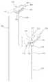
도 3 내지 도 6은 본 발명의 일 구현예에 따른 니들 도구(100)의 구조를 보인 도면이다.3 to 6 show the structure of the
도 3 내지 도 6에 의하면, 상기 니들 도구(100)는, 도관(130)의 단부에 수용홈(112)을 갖는 손잡이(111)가 배치되는 파이프 도구(110);와, 상기 파이프 도구(110)의 도관(130) 내부로 삽입되는 강선(122)을 가지며, 상기 강선(122)의 단부에 배치되며 결합수단을 매개로 상기 수용홈(112) 내에 수용되도록 결합되는 헤드(121)를 갖는 강선 도구(120);를 구비한다.3 to 6, the
상기 파이프 도구(110)의 손잡이(111)는 그 상부에, 강선 도구(120)의 헤드(121)를 수용하기 위해 오목하게 마련된 수용홈(112)을 구비하며, 그 저면에는 만곡부(114)가 형성되어 있다. 상기 수용홈(112)의 양 측면부위에는 강선 도구(120)의 헤드(121) 부위에 형성된 고정돌기(123)가 슬리이딩 결합되는 고정홈(115)이 형성되어 있다. 또한 평면상으로는, 상기 수용홈(112)의 내주면에 파이프 도구(110)와 강선 도구(120) 간의 결합 및 분리를 용이하게 하기 위한 가이드 돌기(113)가 형성되어 있고, 상기 수용홈(112)이 형성된 손잡이(111)의 중앙 부분에 강선 도구의 강선(122)이 도관(130) 내로 삽입되도록 삽입구(116)가 마련된다. 상기 손잡이(111)의 저면에는 도관(130)이 고정부재(118)에 의해 손잡이(111)와 고정되어 있고, 상기 도관(130)은 선단부(시술시 기준)가 테이퍼(117)지는 형태로 마련되어 있다.The
상기 강선도구(120)는 헤드(121)와 강선(122)으로 구성된다. 상기 헤드(121)는 파이프 도구의 작업시 안정감을 주기 위해 형성된 만곡부(114)와 마찬가지로 주로 회전이 용이하도록 회전시 도구를 잡고 있는 손이 미끄러지는 것을 방지하기 위하여 그 전면과 배면으로 복수의 홈을 형성하는 그립부(124)가 마련되어 있다. 상기 그립부(124)의 하단에는 그립감을 좋게 하고 헤드의 중량을 감소하기 위해 외홈부(125)가 마련되어 있다. 상기 헤드(121)의 좌우측면에는 고정돌기(123)가 형성되어 있어 파이프 도구(110)의 고정 홈(115)과 슬라이딩 결합된다. 상기 강선(122)은 그 선단이 척추 뼈에 용이하게 삽입되도록 예를 들어 원통면 경사 절단 형상 또는 다각뿔 형상으로 날카롭고 뾰쪽하게 마련된다.The
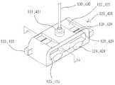
도 7은 강선 도구(120)와 확장관 도구(400)의 요부인 결합부의 구성을 도시한 저면 사시도이고, 도 8 및 도 9는 니들 결합부의 요부 결합 및 분리상태를 보인 도면이다.7 is a bottom perspective view showing the configuration of the coupling portion that is the main portion of the
강선 도구(120)와 확장관(400)은, 도 7에서 보는 바와 같이, 그 저면에, 파이프 도구(110)나 캐뉼러 도구(300)와 결합하기 위하여 상기 도구들(110)(300)에 형성된 가이드 돌기(113)(313)가 안착부(129)(429) 측으로 슬라이딩 진입하는 것을 유도하기 위한 경사 가이드(127)(427)와, 상기 경사 가이드(127)(427)를 따라 도구 간의 결합이 유도되는 가이드 돌기(113)(313)가 역회전에 의해 분리되는 것을 방지하기 위하여 마련된 걸림 턱(128)(428)과, 상기 걸림 턱(128)(428)을 통과하여 가이드 돌기(113)(313)가 고정되는 안착부(129)(429)가 마련되어 있다. 이러한 구 조를 통하여, 강선이 니들 또는 뼈로부터 용이하게 분리될 수 있으며, 확장관이 캐뉼러에 안정적으로 결합될 수 있고 그로부터 손쉽게 분리될 수 있다.The
이와 같은 가이드 돌기(113)(313), 경사 가이드(127)(427) 및 걸림턱(128)(428)의 작동에 따른 실시예를 니들 도구(100)를 통하여 살펴보면, 도 8 및 도 9에서 보는 바와 같다.An embodiment of the operation of the
도 8에 도시된 바와 같이, 파이프 도구(110)에 마련된 가이드 돌기(113)가 강선 도구(120)에 마련된 경사 가이드(127)를 따라 유도되어 걸림턱(128)을 통과하게 되면 강선 도구(120)의 안착부(129)에 안착되고, 이처럼 파이프 도구(110)와 강선 도구(120)가 결합 완료되면, 상기 파이프 도구(110)의 도관(130)에 강선 도구(120)의 강선(122)이 돌출되는 구조를 가지게 된다. 이를 통해 척추 뼈로의 최초의 통로를 개설하는 강선 도구(120)의 기능을 수행할 수 있다.As shown in FIG. 8, when the
단단한 척추 뼈에 삽입된 강선(122)을 다시 척추 뼈로부터 분리하기 위해서는, 도 9에서와 같이 행한다. 즉, 결합된 강선 도구(120)를 파이프 도구(110)로부터 그립부(124)를 잡고 비틀어주게 되면 가이드 돌기(113)가 경사 가이드(127)를 따라 이동하게 되어 강선 도구(120)가 파이프 도구(110)로부터 분리되고, 상기 파이프 도구(110)의 도관(130)으로부터 강선 도구(120)의 강선(122)이 상승되어 척추 뼈로부터 분리되는 구조를 가지게 된다.In order to separate the
도 10은 본 발명의 일 구현예에 따른 스페이서 도구(500)의 구조를 보인 확대도이다. 스페이서(500)는 앞서 기술한 바와 같이 척추 뼈 내부에 풍선 카테터와 같은 공동형성도구가 원활히 삽입될 수 있는 공간을 만들어주기 위한 것이다.10 is an enlarged view showing the structure of a
상기 스페이서(500)는 크게 손잡이(511)와 강선(522)으로 구성된다. 상기 손잡이(511)는 상부에 좌우대칭을 이루는 돌기가 구비되어 있고, 하부에는 만곡진 그립부(524)가 형성되어 있다. 상기와 같은 구조에 의해 손가락을 상기 그립부(524) 사이에 결합하고 손잡이(511)를 움켜진 손바닥을 용이하게 비틀 수 있다. 상기 그립부(524)가 형성된 손잡이(511)의 하단에는 강선(522)이 마련되어 있다. 상기 강선(522)의 선단부(시술시 기준)에는 뼈 내부에 공간을 만들기 용이하도록 나사부(520)를 형성하고 있다. 상기 나사부(520)는 종래의 드릴비트 방식에서 보여지는 과도한 절삭분 등의 문제를 야기하지 않도록, 120도의 위상차를 가지고 나사산이 원통을 일 회전하여 축 방향으로 진행하는 거리가 나사의 축선을 포함하는 단면에서 서로 이웃한 나사산에 대응하는 2점 사이의 축선 방향의 거리의 3배가 되도록 구성된 3줄 나사를 사용하여 이루어진다.The
도 11 및 도 12는 본 발명의 일 구현예에 따른 뼈 치료용 장치의 필러 도구(600)와 푸셔 도구(700)의 작동 전후 상태를 보인 단면도이다.11 and 12 are cross-sectional views showing the state before and after the operation of the
상기 필러 도구(600)는 크게 손잡이(611), 도관(620), 완충구(626)로 구성된다. 상기 손잡이(611)는, 스페이서 도구(500)의 손잡이(511)와 마찬가지로, 상부에 좌우대칭을 이루는 돌기가 구비되어 있고, 그 하부에 만곡진 그립부(624)가 마련되어 있다. 상기 그립부(524)가 형성된 손잡이(511)의 상단에는 푸셔(700)에 구비된 핀(722)이 삽입되기 위한 일정한 높이의 턱을 가지는 완충구(626)가 마련되어 있다. 상기 손잡이(611)의 하단에는 상기 핀(722)이 가이드 되며, 캐뉼러 도구의 도관(330) 내부로 삽입되는 도관(630)이 마련되어 있다.The
또한, 상기 푸셔 도구(700)는 상부에 손잡이(711)가 마련되고, 상기 손잡이(711)의 하단에 핀(722)이 구비되어 있다. 이 때, 상기 손잡이(711)는 눈사람 형태이다.In addition, the
일 실시예를 예를 들면, 상기 필러(600)의 도관(630)에 뼈 충진물질(800), 예를 들어 의료용 시멘트를 삽입한 후 이를 푸셔(700)의 핀(722)을 통하여 밀어줌으로써 도관(630)의 끝으로 삽입되었던 시멘트(800)가 도출되고 이로써 척추 뼈 속으로 시멘트가 충진될 수 있다.For example, the conduit by inserting a
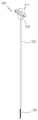
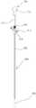
한편 도 13은 본 발명의 뼈 치료용 장치의 일 예로서 니들(100), 가이드(200), 캐뉼러(300), 확장관(400), 스페이서(500), 필러(600) 및 푸셔(700) 도구를 모두 포함하는 장치의 전체구성을 보인 사시도이다.Meanwhile, FIG. 13 is an example of the apparatus for treating bone of the present invention, the
도 13에 의하면, 본 발명의 장치는, 스테인리스 또는 알루미늄으로 이루어지고 도관(130)의 단부에 수용홈(112)을 갖는 손잡이(111)가 배치되는 파이프 도구(110)와, 상기 파이프 도구(110)의 도관(130) 내부로 삽입되는 강선(122)을 가지며 상기 강선(122)의 단부에 배치되어 결합수단을 매개로 상기 수용홈(112) 내에 수용되도록 결합되는 헤드(121)를 갖는 강선 도구(120)를 구비하는 니들 도구(100); 상기 니들 도구(100) 내부에 삽입되며 와이어 핀으로 되어 있는 가이드 도구(200); 상기 가이드 도구(200)로부터 니들 도구(100)를 분리한 후 가이드 도구(200)로 안내되어 뼈 내부로 삽입되며, 도관(330)의 단부에 수용홈(312)을 갖는 손잡이(311)가 배치되는 캐뉼러 도구(300); 상기 캐뉼러 도구(300)의 도관(330) 내부로 삽입되는 확장도관(430)을 가지며, 상기 확장도관(430)의 단부에 배치되어 결 합수단을 매개로 상기 수용홈(312) 내에 수용되도록 결합되는 헤드(421)를 갖는 확장관 도구; 캐뉼러 도구(300)로부터 확장관 도구(400)를 분리한 후 상기 캐뉼러 도구(300)에 삽입되며, 일단부에 나사부(520)가 형성되고 타단부에 손잡이(511)가 배치되는 강선(522)을 갖는 스페이서 도구(500); 상기 스페이서 도구(500)를 분리한 후 상기 캐뉼러 도구(300)에 삽입되며, 일단부에 완충턱(626)이 배치되고 타단부에 도관(630)이 배치되는 손잡이(611)를 갖는 복수의 필러 도구(600); 상기 뼈 충진물질이 삽입된 필러 도구(600)에 삽입되는 핀(722)과, 상기 핀(722)의 단부에 배치되는 손잡이(711)를 구비하는 복수의 푸셔 도구(700);를 구비한다.According to FIG. 13, the apparatus of the present invention comprises a
이러한 장치가 이용되는 척추굴절복원술의 일반적인 시술의 일 실시예를 기술하면 다음과 같다:One embodiment of a general procedure for spinal refractive surgery in which such a device is used is as follows:
제 1 단계, 피시술자의 등을 절개하여 니들의 구성요소 중 강선 도구를 사용하여 피하조직을 관통한 후 척추 뼈의 내부에 삽입하며 이 때 파이프(Pipe)를 포함하는 니들이 함께 척추 뼈의 내부에 삽입된다.In the first step, the incision of the subject is performed and penetrated the subcutaneous tissue using the wire tool among the components of the needle, and then inserted into the inside of the vertebral bone, and the needle including the pipe is inserted together inside the vertebral bone. do.
제 2 단계, 삽입된 니들의 강선 도구를 파이프로부터 분리하고, 와이어 핀을 파이프의 내부에 삽입한 후 위치를 확보하고, 파이프를 삽입된 척추 뼈로부터 제거하여 전체 니들을 분리한다.In the second step, the wire tool of the inserted needle is separated from the pipe, the wire pin is inserted into the inside of the pipe to secure its position, and the pipe is removed from the inserted vertebral bone to separate the entire needle.
제 3 단계, 척추 뼈 내부에 부분 삽입된 와이어 핀을 가이드로 하여 캐뉼러를 삽입하며, 이 때 삽입되는 캐뉼러의 내부에는 삽입이 용이하도록 선단으로 협소하게 테이퍼링된 확장관이 삽입되어 있다.In the third step, the cannula is inserted with the wire pin partially inserted into the vertebral bone as a guide, and a narrowly tapered extension tube is inserted into the inside of the cannula to be inserted to facilitate insertion.
제 4 단계, 확장관 및 와이어 핀을 캐뉼러로부터 분리하고, 캐뉼러의 내부에 스페이서를 삽입하여 이후 풍선 카테터(ballon catheter)가 원활하게 삽입될 수 있는 공간을 만들어준다.The fourth step, the extension tube and the wire pins are separated from the cannula and a spacer is inserted into the cannula to make room for the balloon catheter to be inserted smoothly.
제 5 단계, 선단부(시술시 기준)에 풍선이 마련된 카테터를 캐뉼러를 통하여 척추 뼈의 내부에 삽입하고, 상기 카테터 외부에 별도의 실린더 장치를 결합하며, 상기 결합된 실린더를 동작시켜 카테터에 마련된 풍선을 팽창시킨다.In a fifth step, a catheter provided with a balloon at the distal end portion (inserted during the procedure) is inserted into the vertebral bone through a cannula, and a separate cylinder device is coupled to the outside of the catheter, and the coupled cylinder is operated to provide a catheter. Inflate the balloon.
제 6 단계, 척추 뼈의 몸체가 원래의 형태로 복원되면 상기 풍선 카테터를 캐뉼러로부터 제거하고 필러(filler)의 관 내부에 뼈 충진 물질(예, 의료용 골시멘트(bone cement))을 주입하고 캐뉼러에 삽입한 후 외부에서 상기 필러의 도관에 푸셔를 밀어넣어, 풍선에 의해 형성된 척추 뼈 내부의 공간에 시멘트를 주입하게 된다.Step 6, when the body of the vertebral bone is restored to its original shape, the balloon catheter is removed from the cannula and bone filling material (e.g. medical bone cement) is injected into the tube of the filler and After inserting into the cannula, the pusher is pushed into the conduit of the filler from the outside to inject cement into the space inside the vertebral bone formed by the balloon.
이처럼 상기와 같은 단계를 통하여 손상된 척추 뼈 속에 시멘트가 주입되어 경화됨으로써, 원래의 형태로 척추 뼈의 몸체가 복원될 수 있다.In this way, the cement is injected into the damaged vertebral bone through the above-described steps, and thus, the body of the vertebral bone can be restored to its original shape.
본 발명은 표피에서 뼈로의 통로를 제공하는 카테터 액세서리 도구에 있어, 사용시에 불편함이 따르는 문제를 개선하고, 기능적인 구조를 제공함으로써 시술자와 피시술자 간에 시술 후 만족도를 높이고, 보다 효율적으로 척추굴절복원술용 풍선 카테터 시술이 이루어질 수 있도록 하는 획기적인 뼈 치료용 장치를 제공하므로, 그 산업상 이용가능성이 뛰어나다 할 수 있다.The present invention provides a catheter accessory tool that provides a passage from the epidermis to the bone, and improves the post-operation satisfaction between the operator and the subject by providing a functional structure and improving a problem caused by inconvenience. It provides a breakthrough bone therapy device that allows the balloon catheter procedure for the dragon, it can be said that the industrial applicability is excellent.
도 1은 본 발명의 일 구현예에 따른 도킹(결합)된 상태의 캐뉼러 도구 및 확장관 도구의 구조를 보인 사시도.1 is a perspective view showing the structure of a cannula tool and an extension tube tool in a docked state in accordance with an embodiment of the present invention.
도 2는 본 발명의 일 구현예에 따른 캐뉼러 도구, 확장관 도구 및 가이드 도구를 도시한 분리도.2 is an exploded view showing a cannula tool, an extension tube tool and a guide tool according to one embodiment of the invention.
도 3은 본 발명의 일 구현예에 따른 도킹(결합)된 상태의 니들 도구의 구조를 보인 사시도.Figure 3 is a perspective view showing the structure of the needle tool in the docked (coupled) state according to an embodiment of the present invention.
도 4는 본 발명의 일 구현예에 따른 니들 도구의 구조를 보인 단면도,4 is a cross-sectional view showing the structure of a needle tool according to an embodiment of the present invention,
도 5는 본 발명의 일 구현예에 따른 강선의 선단부(시술시 기준) 구조를 보인 확대도.5 is an enlarged view showing the structure of the leading end portion (based on the procedure) of the steel wire according to an embodiment of the present invention.
도 6은 본 발명의 일 구현예에 따른 니들 도구의 구조를 보인 분리도.Figure 6 is an exploded view showing the structure of the needle tool according to an embodiment of the present invention.
도 7은 강선도구와 확장관 도구의 요부인 결합부의 구성을 도시한 저면 사시도.Figure 7 is a bottom perspective view showing the configuration of the coupling portion that is the main portion of the steel wire tool and expansion tube tool.
도 8은 도 3 내지 도 6에 있어서, 결합부의 요부 결합상태를 보인 개략도.8 is a schematic view showing the main portion engaged state of the coupling portion in FIGS.
도 9는 도 3 내지 도 6에 있어서, 결합부의 요부 분리상태를 보인 개략도.9 is a schematic view showing a main portion separated state of the coupling portion in Figs.
도 10은 본 발명의 일 구현예에 따른 스페이서 도구의 구조를 보인 확대도.10 is an enlarged view showing the structure of a spacer tool according to an embodiment of the present invention.
도 11은 본 발명의 일 구현예에 따른 뼈 치료용 장치의 필러와 푸셔의 작동전 상태를 보인 단면도.Figure 11 is a cross-sectional view showing the pre-operation state of the filler and the pusher of the device for bone treatment according to an embodiment of the present invention.
도 12는 본 발명의 일 구현예에 따른 뼈 치료용 장치의 필러와 푸셔의 작동시 상태를 보인 단면도.12 is a cross-sectional view showing a state of operation of the filler and the pusher of the device for bone treatment according to an embodiment of the present invention.
도 13은 본 발명의 일 구현예에 따른 뼈 치료용 장치의 전체구성을 보인 사시도.Figure 13 is a perspective view showing the overall configuration of the device for bone treatment according to an embodiment of the present invention.
Claims (17)
Translated fromKoreanPriority Applications (4)
| Application Number | Priority Date | Filing Date | Title |
|---|---|---|---|
| CN200880116281XACN101861183B (en) | 2007-09-14 | 2008-09-12 | Apparatus for treating bone |
| EP08830455AEP2195067A4 (en) | 2007-09-14 | 2008-09-12 | Apparatus for treating bone |
| US12/209,438US20090076520A1 (en) | 2007-09-14 | 2008-09-12 | Apparatus For Treating Bone |
| PCT/KR2008/005407WO2009035291A2 (en) | 2007-09-14 | 2008-09-12 | Apparatus for treating bone |
Applications Claiming Priority (2)
| Application Number | Priority Date | Filing Date | Title |
|---|---|---|---|
| KR20070093572 | 2007-09-14 | ||
| KR1020070093572 | 2007-09-14 |
Publications (2)
| Publication Number | Publication Date |
|---|---|
| KR20090028436A KR20090028436A (en) | 2009-03-18 |
| KR100950990B1true KR100950990B1 (en) | 2010-04-02 |
Family
ID=40695690
Family Applications (1)
| Application Number | Title | Priority Date | Filing Date |
|---|---|---|---|
| KR1020080089358AActiveKR100950990B1 (en) | 2007-09-14 | 2008-09-10 | Bone Therapy |
Country Status (5)
| Country | Link |
|---|---|
| US (1) | US20090076520A1 (en) |
| EP (1) | EP2195067A4 (en) |
| KR (1) | KR100950990B1 (en) |
| CN (1) | CN101861183B (en) |
| WO (1) | WO2009035291A2 (en) |
Cited By (1)
| Publication number | Priority date | Publication date | Assignee | Title |
|---|---|---|---|---|
| KR200453097Y1 (en)* | 2009-04-02 | 2011-04-05 | 이달호 | Maxillary remain bone final boring combined use maxillary sinus membrane seperator |
Families Citing this family (97)
| Publication number | Priority date | Publication date | Assignee | Title |
|---|---|---|---|---|
| US8361067B2 (en) | 2002-09-30 | 2013-01-29 | Relievant Medsystems, Inc. | Methods of therapeutically heating a vertebral body to treat back pain |
| US9918740B2 (en) | 2006-02-27 | 2018-03-20 | Biomet Manufacturing, Llc | Backup surgical instrument system and method |
| US8591516B2 (en) | 2006-02-27 | 2013-11-26 | Biomet Manufacturing, Llc | Patient-specific orthopedic instruments |
| US8603180B2 (en)* | 2006-02-27 | 2013-12-10 | Biomet Manufacturing, Llc | Patient-specific acetabular alignment guides |
| US20110046735A1 (en)* | 2006-02-27 | 2011-02-24 | Biomet Manufacturing Corp. | Patient-Specific Implants |
| US8864769B2 (en) | 2006-02-27 | 2014-10-21 | Biomet Manufacturing, Llc | Alignment guides with patient-specific anchoring elements |
| US9173661B2 (en) | 2006-02-27 | 2015-11-03 | Biomet Manufacturing, Llc | Patient specific alignment guide with cutting surface and laser indicator |
| US9339278B2 (en) | 2006-02-27 | 2016-05-17 | Biomet Manufacturing, Llc | Patient-specific acetabular guides and associated instruments |
| US8407067B2 (en) | 2007-04-17 | 2013-03-26 | Biomet Manufacturing Corp. | Method and apparatus for manufacturing an implant |
| US9345548B2 (en) | 2006-02-27 | 2016-05-24 | Biomet Manufacturing, Llc | Patient-specific pre-operative planning |
| US8608749B2 (en) | 2006-02-27 | 2013-12-17 | Biomet Manufacturing, Llc | Patient-specific acetabular guides and associated instruments |
| US9113971B2 (en) | 2006-02-27 | 2015-08-25 | Biomet Manufacturing, Llc | Femoral acetabular impingement guide |
| US8377066B2 (en) | 2006-02-27 | 2013-02-19 | Biomet Manufacturing Corp. | Patient-specific elbow guides and associated methods |
| US10278711B2 (en) | 2006-02-27 | 2019-05-07 | Biomet Manufacturing, Llc | Patient-specific femoral guide |
| US8535387B2 (en)* | 2006-02-27 | 2013-09-17 | Biomet Manufacturing, Llc | Patient-specific tools and implants |
| US9289253B2 (en) | 2006-02-27 | 2016-03-22 | Biomet Manufacturing, Llc | Patient-specific shoulder guide |
| US8568487B2 (en) | 2006-02-27 | 2013-10-29 | Biomet Manufacturing, Llc | Patient-specific hip joint devices |
| US20150335438A1 (en) | 2006-02-27 | 2015-11-26 | Biomet Manufacturing, Llc. | Patient-specific augments |
| US9907659B2 (en) | 2007-04-17 | 2018-03-06 | Biomet Manufacturing, Llc | Method and apparatus for manufacturing an implant |
| US8608748B2 (en) | 2006-02-27 | 2013-12-17 | Biomet Manufacturing, Llc | Patient specific guides |
| US8092465B2 (en) | 2006-06-09 | 2012-01-10 | Biomet Manufacturing Corp. | Patient specific knee alignment guide and associated method |
| US8133234B2 (en) | 2006-02-27 | 2012-03-13 | Biomet Manufacturing Corp. | Patient specific acetabular guide and method |
| US8858561B2 (en) | 2006-06-09 | 2014-10-14 | Blomet Manufacturing, LLC | Patient-specific alignment guide |
| US8241293B2 (en) | 2006-02-27 | 2012-08-14 | Biomet Manufacturing Corp. | Patient specific high tibia osteotomy |
| US7967868B2 (en) | 2007-04-17 | 2011-06-28 | Biomet Manufacturing Corp. | Patient-modified implant and associated method |
| US9795399B2 (en) | 2006-06-09 | 2017-10-24 | Biomet Manufacturing, Llc | Patient-specific knee alignment guide and associated method |
| USD603502S1 (en)* | 2007-12-03 | 2009-11-03 | Orthopedic Development Corporation | Surgical impactor |
| WO2009129272A2 (en) | 2008-04-15 | 2009-10-22 | Lonnie Paulos | Tissue microfracture apparatus and methods of use |
| US10028753B2 (en) | 2008-09-26 | 2018-07-24 | Relievant Medsystems, Inc. | Spine treatment kits |
| CA2737374C (en) | 2008-09-26 | 2017-03-28 | Relievant Medsystems, Inc. | Systems and methods for navigating an instrument through bone |
| KR100919623B1 (en)* | 2009-04-06 | 2009-09-30 | (주)비엠코리아 | Instruments that access interior body regions |
| US8377013B2 (en)* | 2009-08-05 | 2013-02-19 | The University Of Toledo | Needle for directional control of the injection of bone cement into a vertebral compression fracture |
| DE102009028503B4 (en) | 2009-08-13 | 2013-11-14 | Biomet Manufacturing Corp. | Resection template for the resection of bones, method for producing such a resection template and operation set for performing knee joint surgery |
| US8632547B2 (en) | 2010-02-26 | 2014-01-21 | Biomet Sports Medicine, Llc | Patient-specific osteotomy devices and methods |
| KR101150283B1 (en) | 2010-03-15 | 2012-05-24 | (주)엘앤케이바이오메드 | Injection device for bone cement |
| US9144501B1 (en) | 2010-07-16 | 2015-09-29 | Nuvasive, Inc. | Fracture reduction device and methods |
| US9271744B2 (en) | 2010-09-29 | 2016-03-01 | Biomet Manufacturing, Llc | Patient-specific guide for partial acetabular socket replacement |
| US9968376B2 (en) | 2010-11-29 | 2018-05-15 | Biomet Manufacturing, Llc | Patient-specific orthopedic instruments |
| US9241745B2 (en) | 2011-03-07 | 2016-01-26 | Biomet Manufacturing, Llc | Patient-specific femoral version guide |
| US8715289B2 (en) | 2011-04-15 | 2014-05-06 | Biomet Manufacturing, Llc | Patient-specific numerically controlled instrument |
| US9675400B2 (en) | 2011-04-19 | 2017-06-13 | Biomet Manufacturing, Llc | Patient-specific fracture fixation instrumentation and method |
| US8956364B2 (en) | 2011-04-29 | 2015-02-17 | Biomet Manufacturing, Llc | Patient-specific partial knee guides and other instruments |
| US8668700B2 (en) | 2011-04-29 | 2014-03-11 | Biomet Manufacturing, Llc | Patient-specific convertible guides |
| US8532807B2 (en) | 2011-06-06 | 2013-09-10 | Biomet Manufacturing, Llc | Pre-operative planning and manufacturing method for orthopedic procedure |
| US9084618B2 (en) | 2011-06-13 | 2015-07-21 | Biomet Manufacturing, Llc | Drill guides for confirming alignment of patient-specific alignment guides |
| US8764760B2 (en) | 2011-07-01 | 2014-07-01 | Biomet Manufacturing, Llc | Patient-specific bone-cutting guidance instruments and methods |
| US20130001121A1 (en) | 2011-07-01 | 2013-01-03 | Biomet Manufacturing Corp. | Backup kit for a patient-specific arthroplasty kit assembly |
| US8597365B2 (en) | 2011-08-04 | 2013-12-03 | Biomet Manufacturing, Llc | Patient-specific pelvic implants for acetabular reconstruction |
| US9066734B2 (en) | 2011-08-31 | 2015-06-30 | Biomet Manufacturing, Llc | Patient-specific sacroiliac guides and associated methods |
| US9295497B2 (en) | 2011-08-31 | 2016-03-29 | Biomet Manufacturing, Llc | Patient-specific sacroiliac and pedicle guides |
| US9386993B2 (en) | 2011-09-29 | 2016-07-12 | Biomet Manufacturing, Llc | Patient-specific femoroacetabular impingement instruments and methods |
| KR20130046337A (en) | 2011-10-27 | 2013-05-07 | 삼성전자주식회사 | Multi-view device and contol method thereof, display apparatus and contol method thereof, and display system |
| US9451973B2 (en) | 2011-10-27 | 2016-09-27 | Biomet Manufacturing, Llc | Patient specific glenoid guide |
| US9301812B2 (en) | 2011-10-27 | 2016-04-05 | Biomet Manufacturing, Llc | Methods for patient-specific shoulder arthroplasty |
| US9554910B2 (en) | 2011-10-27 | 2017-01-31 | Biomet Manufacturing, Llc | Patient-specific glenoid guide and implants |
| WO2013062848A1 (en) | 2011-10-27 | 2013-05-02 | Biomet Manufacturing Corporation | Patient-specific glenoid guides |
| AU2012362524B2 (en) | 2011-12-30 | 2018-12-13 | Relievant Medsystems, Inc. | Systems and methods for treating back pain |
| US9237950B2 (en) | 2012-02-02 | 2016-01-19 | Biomet Manufacturing, Llc | Implant with patient-specific porous structure |
| PL2822483T3 (en)* | 2012-03-09 | 2016-05-31 | George J Sikora | Microfracture apparatuses |
| US10588691B2 (en) | 2012-09-12 | 2020-03-17 | Relievant Medsystems, Inc. | Radiofrequency ablation of tissue within a vertebral body |
| WO2014071161A1 (en) | 2012-11-05 | 2014-05-08 | Relievant Medsystems, Inc. | System and methods for creating curved paths through bone and modulating nerves within the bone |
| US9060788B2 (en) | 2012-12-11 | 2015-06-23 | Biomet Manufacturing, Llc | Patient-specific acetabular guide for anterior approach |
| US9204977B2 (en) | 2012-12-11 | 2015-12-08 | Biomet Manufacturing, Llc | Patient-specific acetabular guide for anterior approach |
| US8920512B2 (en) | 2012-12-19 | 2014-12-30 | Biomet Sports Medicine, Llc | Method and apparatus for pre-forming a high tibial osteotomy |
| US9839438B2 (en) | 2013-03-11 | 2017-12-12 | Biomet Manufacturing, Llc | Patient-specific glenoid guide with a reusable guide holder |
| US9579107B2 (en) | 2013-03-12 | 2017-02-28 | Biomet Manufacturing, Llc | Multi-point fit for patient specific guide |
| US9498233B2 (en) | 2013-03-13 | 2016-11-22 | Biomet Manufacturing, Llc. | Universal acetabular guide and associated hardware |
| US9826981B2 (en) | 2013-03-13 | 2017-11-28 | Biomet Manufacturing, Llc | Tangential fit of patient-specific guides |
| US9517145B2 (en) | 2013-03-15 | 2016-12-13 | Biomet Manufacturing, Llc | Guide alignment system and method |
| CN103251445B (en)* | 2013-04-19 | 2015-04-22 | 南京医科大学第一附属医院 | Device for operating vertebroplasty through unilateral vertebral pedicle |
| US9724151B2 (en) | 2013-08-08 | 2017-08-08 | Relievant Medsystems, Inc. | Modulating nerves within bone using bone fasteners |
| US10238401B2 (en) | 2013-09-23 | 2019-03-26 | Arthrosurface, Inc. | Microfracture apparatuses and methods |
| US20150112349A1 (en) | 2013-10-21 | 2015-04-23 | Biomet Manufacturing, Llc | Ligament Guide Registration |
| KR20150047340A (en)* | 2013-10-24 | 2015-05-04 | 안용철 | Apparatus for Treating Bone |
| US10282488B2 (en) | 2014-04-25 | 2019-05-07 | Biomet Manufacturing, Llc | HTO guide with optional guided ACL/PCL tunnels |
| US9408616B2 (en) | 2014-05-12 | 2016-08-09 | Biomet Manufacturing, Llc | Humeral cut guide |
| US9839436B2 (en) | 2014-06-03 | 2017-12-12 | Biomet Manufacturing, Llc | Patient-specific glenoid depth control |
| US9561040B2 (en) | 2014-06-03 | 2017-02-07 | Biomet Manufacturing, Llc | Patient-specific glenoid depth control |
| US9826994B2 (en) | 2014-09-29 | 2017-11-28 | Biomet Manufacturing, Llc | Adjustable glenoid pin insertion guide |
| US9833245B2 (en) | 2014-09-29 | 2017-12-05 | Biomet Sports Medicine, Llc | Tibial tubercule osteotomy |
| US10702395B2 (en) | 2014-10-01 | 2020-07-07 | Arthrosurface, Inc. | Microfracture apparatuses and methods |
| US9820868B2 (en) | 2015-03-30 | 2017-11-21 | Biomet Manufacturing, Llc | Method and apparatus for a pin apparatus |
| US10568647B2 (en) | 2015-06-25 | 2020-02-25 | Biomet Manufacturing, Llc | Patient-specific humeral guide designs |
| US10226262B2 (en) | 2015-06-25 | 2019-03-12 | Biomet Manufacturing, Llc | Patient-specific humeral guide designs |
| CN105559869B (en)* | 2016-02-06 | 2019-08-20 | 贺新宁 | A kind of general percutaneous cervical arc root nail stick internal fixation system |
| CN105596077A (en)* | 2016-02-06 | 2016-05-25 | 贺新宁 | Universal screw-setting device for pedicle screw |
| US10722310B2 (en) | 2017-03-13 | 2020-07-28 | Zimmer Biomet CMF and Thoracic, LLC | Virtual surgery planning system and method |
| CN108836451B (en)* | 2018-07-11 | 2020-12-15 | 上海锐植医疗器械有限公司 | An orthopedic surgery trocar |
| CN108938058A (en)* | 2018-08-13 | 2018-12-07 | 苏州爱得科技发展股份有限公司 | A kind of self-positioning locking percutaneous needle |
| KR102177008B1 (en)* | 2018-10-01 | 2020-11-10 | 가톨릭대학교 산학협력단 | Medical guide unit capable of crushing bone |
| AU2020346827A1 (en) | 2019-09-12 | 2022-03-31 | Relievant Medsystems, Inc. | Systems and methods for tissue modulation |
| EP3892215B1 (en)* | 2020-04-09 | 2023-10-11 | Biedermann Technologies GmbH & Co. KG | Surgical instrument |
| US12082876B1 (en) | 2020-09-28 | 2024-09-10 | Relievant Medsystems, Inc. | Introducer drill |
| EP4268150A4 (en) | 2020-12-22 | 2024-12-18 | Relievant Medsystems, Inc. | PREDICTION OF CANDIDATES FOR SPINAL NEUROMODULATION |
| CN113288390B (en)* | 2021-05-21 | 2024-08-20 | 山东威高骨科材料股份有限公司 | Detachable opening puncture tool |
| CN113925576B (en)* | 2021-07-01 | 2024-07-30 | 上海锐植医疗器械有限公司 | A puncture opener |
| US12433668B1 (en) | 2021-11-08 | 2025-10-07 | Relievant Medsystems, Inc. | Impedance stoppage mitigation during radiofrequency tissue ablation procedures |
Citations (4)
| Publication number | Priority date | Publication date | Assignee | Title |
|---|---|---|---|---|
| US4838282A (en) | 1987-02-26 | 1989-06-13 | Manan Manufacturing Co., Inc. | Bone biopsy needle assembly |
| US5257632A (en) | 1992-09-09 | 1993-11-02 | Symbiosis Corporation | Coaxial bone marrow biopsy coring and aspirating needle assembly and method of use thereof |
| US6613018B2 (en) | 2001-02-20 | 2003-09-02 | Vita Licensing, Inc. | System and kit for delivery of restorative materials |
| US6749595B1 (en) | 2000-06-15 | 2004-06-15 | Kieran P. J. Murphy | Cement delivery needle |
Family Cites Families (21)
| Publication number | Priority date | Publication date | Assignee | Title |
|---|---|---|---|---|
| US5279306B1 (en)* | 1981-03-16 | 1998-06-02 | Creative Res & Mfg | Biopsy needle |
| US4630616A (en)* | 1984-06-15 | 1986-12-23 | Berkley And Company, Inc. | Bone marrow needle |
| US4793363A (en)* | 1986-09-11 | 1988-12-27 | Sherwood Medical Company | Biopsy needle |
| US4919153A (en)* | 1988-10-11 | 1990-04-24 | Origin Medsystems, Inc. | Method and apparatus for removing pre-placed prosthetic joints and preparing for their replacement |
| US4969888A (en)* | 1989-02-09 | 1990-11-13 | Arie Scholten | Surgical protocol for fixation of osteoporotic bone using inflatable device |
| US5013318A (en)* | 1990-07-31 | 1991-05-07 | Special Devices Incorporated | Medical instrument for measuring depth of fastener hold in bone |
| US5047035A (en)* | 1990-08-10 | 1991-09-10 | Mikhail Michael W E | System for performing hip prosthesis revision surgery |
| US5171248A (en)* | 1991-02-27 | 1992-12-15 | Intermedics Orthopedics, Inc. | Medullary caliper |
| US5423850A (en)* | 1993-10-01 | 1995-06-13 | Berger; J. Lee | Balloon compressor for internal fixation of bone fractures |
| US6241734B1 (en)* | 1998-08-14 | 2001-06-05 | Kyphon, Inc. | Systems and methods for placing materials into bone |
| US6716216B1 (en)* | 1998-08-14 | 2004-04-06 | Kyphon Inc. | Systems and methods for treating vertebral bodies |
| US5468245A (en)* | 1994-02-03 | 1995-11-21 | Vargas, Iii; Joseph H. | Biomedical cement bonding enhancer |
| US5464254A (en)* | 1994-08-29 | 1995-11-07 | Moore Business Forms, Inc. | Fishing license protector |
| US5807275A (en)* | 1995-07-19 | 1998-09-15 | Medical Biopsy, Inc. | Biopsy needle |
| US6468279B1 (en)* | 1998-01-27 | 2002-10-22 | Kyphon Inc. | Slip-fit handle for hand-held instruments that access interior body regions |
| US6575919B1 (en)* | 1999-10-19 | 2003-06-10 | Kyphon Inc. | Hand-held instruments that access interior body regions |
| US7815649B2 (en)* | 2000-04-07 | 2010-10-19 | Kyphon SÀRL | Insertion devices and method of use |
| US6312394B1 (en)* | 2000-04-25 | 2001-11-06 | Manan Medical Products, Inc. | Bone marrow biopsy device |
| US7081123B2 (en)* | 2002-06-18 | 2006-07-25 | Musculoskeletal Transplant Foundation | Bone marrow aspiration instrument |
| US7582107B2 (en)* | 2003-02-03 | 2009-09-01 | Integra Lifesciences Corporation | Compression screw apparatuses, systems and methods |
| US20070010843A1 (en)* | 2005-07-07 | 2007-01-11 | Stryker Corporation | Medical apparatus with cannula and releasable handle assembly for accessing remote anatomical sites |
- 2008
- 2008-09-10KRKR1020080089358Apatent/KR100950990B1/enactiveActive
- 2008-09-12WOPCT/KR2008/005407patent/WO2009035291A2/enactiveApplication Filing
- 2008-09-12CNCN200880116281XApatent/CN101861183B/ennot_activeExpired - Fee Related
- 2008-09-12EPEP08830455Apatent/EP2195067A4/ennot_activeWithdrawn
- 2008-09-12USUS12/209,438patent/US20090076520A1/ennot_activeAbandoned
Patent Citations (4)
| Publication number | Priority date | Publication date | Assignee | Title |
|---|---|---|---|---|
| US4838282A (en) | 1987-02-26 | 1989-06-13 | Manan Manufacturing Co., Inc. | Bone biopsy needle assembly |
| US5257632A (en) | 1992-09-09 | 1993-11-02 | Symbiosis Corporation | Coaxial bone marrow biopsy coring and aspirating needle assembly and method of use thereof |
| US6749595B1 (en) | 2000-06-15 | 2004-06-15 | Kieran P. J. Murphy | Cement delivery needle |
| US6613018B2 (en) | 2001-02-20 | 2003-09-02 | Vita Licensing, Inc. | System and kit for delivery of restorative materials |
Cited By (1)
| Publication number | Priority date | Publication date | Assignee | Title |
|---|---|---|---|---|
| KR200453097Y1 (en)* | 2009-04-02 | 2011-04-05 | 이달호 | Maxillary remain bone final boring combined use maxillary sinus membrane seperator |
Also Published As
| Publication number | Publication date |
|---|---|
| CN101861183A (en) | 2010-10-13 |
| EP2195067A2 (en) | 2010-06-16 |
| KR20090028436A (en) | 2009-03-18 |
| US20090076520A1 (en) | 2009-03-19 |
| WO2009035291A2 (en) | 2009-03-19 |
| EP2195067A4 (en) | 2012-12-19 |
| WO2009035291A3 (en) | 2009-05-14 |
| CN101861183B (en) | 2012-10-03 |
Similar Documents
| Publication | Publication Date | Title |
|---|---|---|
| KR100950990B1 (en) | Bone Therapy | |
| KR100950989B1 (en) | Device for transdermal delivery of bone filling material | |
| EP3205371B1 (en) | Telescopic percutaneous tissue dilation systems and related methods of producing | |
| CA2677644C (en) | Device, system and method for delivering a curable material into bone | |
| US9387313B2 (en) | Telescopic percutaneous tissue dilation systems and related methods | |
| ES2357496T3 (en) | DEVICE AND SYSTEM FOR ADMINISTRATION OF A CURABLE MATERIAL IN A BONE. | |
| CN104116555B (en) | Surgical tools, kits for facet treatment of spinal joints for pain relief | |
| KR101150283B1 (en) | Injection device for bone cement | |
| JP2007511324A (en) | Windowed bone tap and method | |
| BRPI0616369A2 (en) | surgical drill, bone cutting system and bone removal method | |
| CN201379636Y (en) | Percutaneous puncturing spine posterior vertebral pedicle nail bar fixing system | |
| CN102973314A (en) | Thoracolumbar spine posterior minimally invasive bone cement spine internal fixation system and application | |
| CN110115611A (en) | A kind of operation tool for caput femoris necrosis bone grafting | |
| CN100490753C (en) | A set of minimally invasive lumbosacral anterior fusion and internal fixation surgical instrument and method of use | |
| CN202313683U (en) | Posterior thoracolumbar minimally-invasive bone cement spinal internal fixing system | |
| KR200409151Y1 (en) | Spine Surgical Spiral Pipe | |
| CN203749544U (en) | Minimally invasive thoracolumbar posterior percutaneous internal fixation system | |
| CN203873868U (en) | Pedicle screw rod-holding device for minimally invasive surgery | |
| KR20090110983A (en) | Bone Cement Injection Kit | |
| KR100963993B1 (en) | Instruments that access interior body regions | |
| KR100476972B1 (en) | Cathter struction for balloon spinal correction | |
| CN203873865U (en) | Bar holding device | |
| KR200361374Y1 (en) | Surgical device for spiral vertebral column | |
| KR200404913Y1 (en) | Needle For Spine Surgery | |
| CN111449717B (en) | Pedicle screw channel construction device |
Legal Events
| Date | Code | Title | Description |
|---|---|---|---|
| A201 | Request for examination | ||
| PA0109 | Patent application | Patent event code:PA01091R01D Comment text:Patent Application Patent event date:20080910 | |
| PA0201 | Request for examination | ||
| PG1501 | Laying open of application | ||
| A302 | Request for accelerated examination | ||
| PA0302 | Request for accelerated examination | Patent event date:20091006 Patent event code:PA03022R01D Comment text:Request for Accelerated Examination Patent event date:20080910 Patent event code:PA03021R01I Comment text:Patent Application | |
| E902 | Notification of reason for refusal | ||
| PE0902 | Notice of grounds for rejection | Comment text:Notification of reason for refusal Patent event date:20091124 Patent event code:PE09021S01D | |
| E701 | Decision to grant or registration of patent right | ||
| PE0701 | Decision of registration | Patent event code:PE07011S01D Comment text:Decision to Grant Registration Patent event date:20100218 | |
| GRNT | Written decision to grant | ||
| PR0701 | Registration of establishment | Comment text:Registration of Establishment Patent event date:20100326 Patent event code:PR07011E01D | |
| PR1002 | Payment of registration fee | Payment date:20100326 End annual number:3 Start annual number:1 | |
| PG1601 | Publication of registration | ||
| FPAY | Annual fee payment | Payment date:20130327 Year of fee payment:4 | |
| PR1001 | Payment of annual fee | Payment date:20130327 Start annual number:4 End annual number:4 | |
| FPAY | Annual fee payment | Payment date:20140219 Year of fee payment:7 | |
| PR1001 | Payment of annual fee | Payment date:20140219 Start annual number:5 End annual number:7 | |
| FPAY | Annual fee payment | Payment date:20170109 Year of fee payment:8 | |
| PR1001 | Payment of annual fee | Payment date:20170109 Start annual number:8 End annual number:8 | |
| FPAY | Annual fee payment | Payment date:20190220 Year of fee payment:10 | |
| PR1001 | Payment of annual fee | Payment date:20190220 Start annual number:10 End annual number:10 | |
| PR1001 | Payment of annual fee | Payment date:20210218 Start annual number:12 End annual number:12 | |
| PR1001 | Payment of annual fee | Payment date:20220328 Start annual number:13 End annual number:13 | |
| PR1001 | Payment of annual fee | Payment date:20230327 Start annual number:14 End annual number:14 | |
| PR1001 | Payment of annual fee | Payment date:20240326 Start annual number:15 End annual number:15 | |
| PR1001 | Payment of annual fee | Payment date:20250326 Start annual number:16 End annual number:16 |