KR100950567B1 - Cctv camera system - Google Patents
Cctv camera systemDownload PDFInfo
- Publication number
- KR100950567B1 KR100950567B1KR1020090017849AKR20090017849AKR100950567B1KR 100950567 B1KR100950567 B1KR 100950567B1KR 1020090017849 AKR1020090017849 AKR 1020090017849AKR 20090017849 AKR20090017849 AKR 20090017849AKR 100950567 B1KR100950567 B1KR 100950567B1
- Authority
- KR
- South Korea
- Prior art keywords
- information
- signal
- camera
- image
- traffic
- Prior art date
- Legal status (The legal status is an assumption and is not a legal conclusion. Google has not performed a legal analysis and makes no representation as to the accuracy of the status listed.)
- Active
Links
- 238000004891communicationMethods0.000claimsabstractdescription49
- 230000005540biological transmissionEffects0.000claimsabstractdescription28
- 238000012545processingMethods0.000claimsabstractdescription23
- 230000008054signal transmissionEffects0.000claimsabstractdescription6
- 238000005070samplingMethods0.000claimsabstractdescription5
- 230000007246mechanismEffects0.000claimsabstractdescription4
- 230000004044responseEffects0.000claimsabstractdescription4
- 230000001629suppressionEffects0.000claimsabstractdescription4
- 238000000034methodMethods0.000claimsdescription34
- 230000010363phase shiftEffects0.000claimsdescription5
- 238000007493shaping processMethods0.000claimsdescription5
- 239000000919ceramicSubstances0.000claimsdescription3
- 230000000295complement effectEffects0.000claimsdescription3
- 229910044991metal oxideInorganic materials0.000claimsdescription3
- 150000004706metal oxidesChemical class0.000claimsdescription3
- 239000000758substrateSubstances0.000claimsdescription3
- 230000009977dual effectEffects0.000claimsdescription2
- 230000006855networkingEffects0.000claimsdescription2
- 239000004065semiconductorSubstances0.000claimsdescription2
- 238000012216screeningMethods0.000claims2
- 230000000694effectsEffects0.000abstractdescription3
- 238000004806packaging method and processMethods0.000abstract1
- 230000008569processEffects0.000description9
- 238000010586diagramMethods0.000description5
- 230000006870functionEffects0.000description3
- 238000012544monitoring processMethods0.000description3
- 238000009434installationMethods0.000description2
- 238000013461designMethods0.000description1
- 239000000284extractSubstances0.000description1
- 238000010295mobile communicationMethods0.000description1
- 238000012986modificationMethods0.000description1
- 230000004048modificationEffects0.000description1
- 230000007480spreadingEffects0.000description1
Images


Classifications
- G—PHYSICS
- G08—SIGNALLING
- G08G—TRAFFIC CONTROL SYSTEMS
- G08G1/00—Traffic control systems for road vehicles
- G08G1/01—Detecting movement of traffic to be counted or controlled
- G08G1/042—Detecting movement of traffic to be counted or controlled using inductive or magnetic detectors
- G—PHYSICS
- G08—SIGNALLING
- G08G—TRAFFIC CONTROL SYSTEMS
- G08G1/00—Traffic control systems for road vehicles
- G08G1/09—Arrangements for giving variable traffic instructions
- G08G1/091—Traffic information broadcasting
- G08G1/094—Hardware aspects; Signal processing or signal properties, e.g. frequency bands
- H—ELECTRICITY
- H04—ELECTRIC COMMUNICATION TECHNIQUE
- H04N—PICTORIAL COMMUNICATION, e.g. TELEVISION
- H04N23/00—Cameras or camera modules comprising electronic image sensors; Control thereof
- H04N23/60—Control of cameras or camera modules
- H—ELECTRICITY
- H04—ELECTRIC COMMUNICATION TECHNIQUE
- H04N—PICTORIAL COMMUNICATION, e.g. TELEVISION
- H04N7/00—Television systems
- H04N7/18—Closed-circuit television [CCTV] systems, i.e. systems in which the video signal is not broadcast
- H—ELECTRICITY
- H04—ELECTRIC COMMUNICATION TECHNIQUE
- H04W—WIRELESS COMMUNICATION NETWORKS
- H04W84/00—Network topologies
- H04W84/02—Hierarchically pre-organised networks, e.g. paging networks, cellular networks, WLAN [Wireless Local Area Network] or WLL [Wireless Local Loop]
- H04W84/10—Small scale networks; Flat hierarchical networks
- H04W84/12—WLAN [Wireless Local Area Networks]
Landscapes
- Engineering & Computer Science (AREA)
- Signal Processing (AREA)
- Multimedia (AREA)
- Physics & Mathematics (AREA)
- General Physics & Mathematics (AREA)
- Computer Networks & Wireless Communication (AREA)
- Closed-Circuit Television Systems (AREA)
Abstract
Translated fromKoreanDescription
Translated fromKorean본 발명은 교통정보 영상수집 장치에 관한 것으로, 더욱 상세하게는 CCTV 카메라, 네트워크 카메라(NC), IP 카메라, 웹 카메라 등으로 구성된 교통정보 수집장치로 무선통신 모듈을 장착하여 카메라의 설치 및 교통영상 수집이 용이하도록 한 교통정보 수집을 위한 카메라 장치에 관한 것이다.The present invention relates to a traffic information image collection device, and more particularly, to a traffic information collection device consisting of a CCTV camera, a network camera (NC), an IP camera, a web camera, and the like, by installing a wireless communication module and installing a traffic image. It relates to a camera device for collecting traffic information to facilitate the collection.
일반적으로 소정의 대상 또는 영역을 감시하기 위한 수단으로 건물이나, 은행, 주차장, 도로 등 다양한 장소에 CCTV 카메라가 설치되어 사용된다. 이와 같은 CCTV 카메라 제어시스템은 중앙의 감시통제 제어시스템에서 건물의 각 위치에 설치된 카메라를 원격 제어하고, 해당 카메라로부터 촬영된 영상데이터를 중앙의 감시통제 제어시스템에서 전송 받아 모니터링 및 저장하는 시스템으로 이루어진다.In general, CCTV cameras are installed and used in various places such as buildings, banks, parking lots, and roads as a means for monitoring a predetermined object or area. Such a CCTV camera control system is composed of a system for remotely controlling cameras installed at each location of a building in a central surveillance control system, and receiving and monitoring image data captured by the camera from a central surveillance control system. .
따라서 이와 같은 CCTV 카메라는 피사체의 영상을 취득하기 위한 카메라와, 중앙의 감시통제 제어시스템으로부터 제공된 카메라의 원격제어 데이터에 따라 카메라의 촬영각도 및 방향을 제어하고, 카메라로부터 촬영된 영상 데이터를 중앙의 감시통제 제어시스템으로 전송하기 위한 카메라 제어수단을 포함하는 구성을 갖는 다.Therefore, such a CCTV camera controls the camera's shooting angle and direction according to the camera for acquiring the image of the subject and the remote control data of the camera provided from the central surveillance control system, and the image data taken from the camera And camera control means for transmitting to the surveillance control system.
그러면, 전술된 종래 카메라 제어장치를 도 1을 참조하여 개략적으로 설명하면 다음과 같다.Then, the above-described conventional camera control apparatus is described schematically with reference to FIG.
먼저, 피사체의 영상을 취득하기 위한 카메라 렌즈부(1)와, 카메라 렌즈부(1)의 수평, 수직축(X,Y축) 각도를 조절하기 위한 팬/틸트(PAN/Tilt)조절모터(2)와, 카메라 렌즈부(1)의 초점(focus)과 배율(zoom)을 조절하기 위한 초점/줌 모터(3)와, 상기 팬/틸트조절모터(2) 및 초점/줌 모터(3)를 구동시키기 위한 모터 구동부(4)와, 중앙 원격제어시스템(7)으로부터 전달된 원격제어정보에 따라 상기 모터 구동부(4)를 제어하여 카메라 렌즈부(1)의 팬/틸트 조절 및 초점/줌을 제어하며, 카메라 렌즈부(1)로부터 취득된 영상데이터를 저장 및 중앙 원격제어시스템(7)으로 전송하는 제어부(5)와, 중앙 원격제어시스템(7)과의 데이터 송수신을 위한 데이터송수신부(6)를 포함하여 구성된다.First, a
이와 같은 구성에 따르면 CCTV 카메라 제어장치는 카메라 렌즈부(1)를 통해 취득된 영상데이터는 데이터 송수신부(6)를 통해 중앙 원격제어시스템(7)으로 전송된다. 이때 카메라 렌즈부(1)의 촬영 각도 및 초점/줌은 중앙 원격 제어시스템(9)의 원격제어에 의해 설정된다.According to such a configuration, the CCTV camera control apparatus transmits image data acquired through the
중앙 원격제어시스템(7)에서는 카메라 렌즈부(1)를 통해 감시하고자 하는 영역을 지정하고자 팬/틸트를 조절하여 카메라 렌즈부(1)의 X,Y축 각도를 설정하고, 또한 감시영역 대상에 대하여 초점 및 줌 배율을 설정하게 된다. 이와 같은 제어 데이터는 데이터 송수신부(7)를 통해 제어부(5)로 전달되고, 제어부(5)에서는 이와 같은 제어 데이터를 이용하여 카메라 렌즈부(1)의 팬/틸트 및 초점/줌 배율을 설정하게 된다.The central
모터구동부(4)에서는 상기에서와 같이 제어부(5)로부터 출력되는 제어 데이터를 입력받아 팬/틸트조절모터(2) 및 초점/줌 모터(3)를 구동시켜 카메라 렌즈부(1)의 촬영 각도(PAN/Tilt) 및 초점/줌 배율을 조정하게 되는바, 팬/틸트조절모터(2)가 동작하게 되면, 팬/틸트조절모터(2)에 연결 구성된 다수의 기어가 회전하면서 카메라 렌즈부(1)의 수평,수직 각도(팬/틸트)를 조절하게 된다.The
초점/줌 모터(3)가 동작하게되면, 초점/줌 모터(3)에 연결된 기어가 회전하면서 초점/줌 렌즈의 위치를 조절하여 카메라 렌즈부(1)의 초점 및 줌 배율을 조절하게 된다. 여기서 팬/틸트조절모터(2)를 조절하여 카메라 렌즈부(1)의 촬영 각도를 조절하고, 조절이 완료된 후 초점/줌 조정을 완료하여 그 설정을 완료하게 된다.When the focus /
중앙 원격제어시스템(9)에서는 내부 모니터를 확인하면서 카메라 렌즈부(1)의 위치를 원격 조절하게 되고, CCTV 제어 장치에서는 이와 같은 조절 데이터를 이용하여 상기와 같은 동작과정을 거쳐 카메라의 원격 제어에 의한 동작을 수행하는 것이다.The central remote control system 9 remotely controls the position of the
그런데, 전술한 바와 같이 영상 취득을 목적으로 구성된 카메라는 중앙 원격제어 시스템과의 데이터 송수신을 수행하여, 원격지에서 촬영된 영상을 취득하기 때문에, 카메라와 중앙 원격제어시스템과의 통신이 매우 중요한 구성 중 하나로 인지되고 있다. 특히, 교통정보 수집용으로 적용되는 카메라의 통신 방식은 전력선 통신 또는 유선 모뎀에 의한 통신 방식이 적용되고 있으며, 이를 위한 통신설비에 많은 비용이 따르고 설치의 어려움이 야기되고 있다.However, as described above, since a camera configured for image acquisition performs data transmission and reception with a central remote control system to acquire an image captured at a remote location, communication between the camera and the central remote control system is very important. It is recognized as one. In particular, the communication method of the camera applied for collecting traffic information is a communication method using a power line communication or a wired modem, the communication equipment for this has a lot of costs and difficulty in installation.
본 발명은 이와 같은 문제점을 해결하기 위해 창출된 것으로, 본 발명의 목적은 도로상으로 설치된 교통정보 수집 장치로부터 촬영된 교통 영상을 무선통신에 의해 전송토록 함으로써, 카메라의 설치가 용이한 교통정보 수집을 위한 카메라 장치를 제공함에 있다.The present invention was created to solve the above problems, and an object of the present invention is to transmit a traffic image photographed from a traffic information collecting device installed on a road by wireless communication, so that traffic information can be easily installed by a camera. To provide a camera device for.
본 발명의 다른 목적은, 현존 인프라의 무선 통신망으로 교통영상을 실시간 탑재함에 따라, 무선 단말기를 이용한 지역별 교통정보를 제공받을 수 있어, 교통정체 해소를 유도할 수 있는 교통정보 수집을 위한 카메라 장치를 제공함에 있다.Another object of the present invention is to provide a traffic information for each region using a wireless terminal, as the traffic image is loaded in real time to a wireless communication network of the existing infrastructure, to induce traffic congestion camera device for collecting traffic information In providing.
상기 목적을 달성하기 위한 본 발명의 관점에 따른 교통정보 수집을 위한 카메라 장치는, 교통영상을 수집하기 위한 카메라에 있어서, 도로상의 차량 운행상태를 영상신호로 변환 출력하는 센서모듈; 상기 센서모듈에서 출력되는 전기적 신호에 대한 상관이중 샘플링처리, 노이즈 억제처리 및 자동게인 조절의 신호처리를 행하여 영상신호로서 출력하는 신호 처리부; 시스템의 고유코드 정보 및 무선통신 프로토콜에 따른 데이터 전송 알고리즘이 탑재된 메모리; 상기 영상신호 및 고유코드 정보를 포함하는 교통영상 정보를 무선통신 프로토콜에 따라 변조 출력하는 신호 변조부; 영상신호 전송지시에 응답하여 상기 교통영상 정보를 무선 통신망으로 송출하는 무선 접속부; 및 카메라의 매카니즘 제어를 수행하고, 상기 신호 처리부에 서 제공되는 영상신호를 디지털 정보로 변환하며, 상기 메모리로 기 설정된 고유코드 정보를 추출한 후, 무선통신 프로토콜에 따라 상기 디지털 정보 및 고유코드 정보를 패키지화된 정보로 가공하여 상기 신호 변조부로 제공하며, 상기 무선 접속부로 영상신호 전송을 지시하는 제어부로 이루어진 것을 특징으로 한다.Camera apparatus for collecting traffic information according to an aspect of the present invention for achieving the above object, Camera for collecting a traffic image, the sensor module for converting and outputting the vehicle driving state on the road to an image signal; A signal processor which performs correlation double sampling processing, noise suppression processing, and automatic gain control signal processing on the electrical signal output from the sensor module and outputs it as an image signal; A memory equipped with a unique code information of a system and a data transmission algorithm according to a wireless communication protocol; A signal modulator for modulating and outputting traffic video information including the video signal and unique code information according to a wireless communication protocol; A wireless connection unit for transmitting the traffic image information to a wireless communication network in response to a video signal transmission instruction; And controlling a camera mechanism, converting an image signal provided from the signal processor into digital information, extracting predetermined code information into the memory, and converting the digital information and unique code information according to a wireless communication protocol. It is processed into packaged information and provided to the signal modulator, and characterized in that the control unit for instructing the video signal transmission to the wireless connection.
구체적으로, 상기 카메라는 교통정보 수집을 위한 CCTV 카메라, 웹 카메라, 네트워크 카메라, IP 카메라 중 어느 하나인 것을 특징으로 한다.Specifically, the camera is any one of a CCTV camera, a web camera, a network camera, an IP camera for collecting traffic information.
본 발명은 각 도로별로 설치된 교통정보 수집장치에서 촬영된 교통영상을 무선 통신망으로 실시간 탑재하도록 함에 따라, 휴대폰, 무선 노트북 등과 같은 무선 단말을 통해 주변 교통정보를 쉽게 수신할 수 있어 교통정보의 활용성을 증대시킬 수 있는 효과가 있다. 또한, 본 발명에 따른 교통정보 수집장치는 유선통신망과 접속하기 위한 통신설비의 공정을 배제함으로써, 설비에 따른 경비절감 효과를 갖는다.According to the present invention, the traffic information collected by the traffic information collecting device installed in each road is mounted in real time through a wireless communication network, so that the surrounding traffic information can be easily received through a wireless terminal such as a mobile phone or a wireless notebook. There is an effect that can increase. In addition, the traffic information collecting device according to the present invention has a cost-saving effect according to the facility by excluding the process of the communication facility for connecting to the wired communication network.
이하, 본 발명의 바람직한 실시 예를 첨부된 예시도면에 의거 상세히 설명하면 다음과 같다.Hereinafter, preferred embodiments of the present invention will be described in detail with reference to the accompanying drawings.
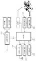
도 2는 본 발명에서 제시되는 교통정보 수집장치의 주요 기능을 설명하기 위한 구성도이다. 먼저, 본 발명에서 기술되는 카메라는 CCTV 카메라, 웹 카메라, 네 트워크 카메라, IP 카메라를 총칭하며, 이러한 카메라의 주요 기능으로서 교통정보 수집을 본 발명의 실시 예로 한다. 따라서, 본 발명에 따른 교통정보 수집장치는 도로상으로 설치되는 교통영상 수집 카메라를 포함하여, 건물 내외에 설치되어 침입자를 감시하기 위한 CCTV 카메라로 적용될 수 있을 것이다.2 is a configuration diagram for explaining the main functions of the traffic information collecting device presented in the present invention. First, the cameras described in the present invention collectively include CCTV cameras, web cameras, network cameras, and IP cameras, and traffic information collection is an embodiment of the present invention as a main function of such a camera. Accordingly, the traffic information collecting device according to the present invention may be applied to a CCTV camera for monitoring an intruder installed inside and outside a building, including a traffic image collecting camera installed on a road.
통상적으로 교통정보 수집을 위한 카메라는 고정 설치되는 반면, 상기한 CCTV 카메라는 피사체 감시를 목적으로 하기 때문에 유동 제어가 가능하다. 이와 같이 카메라의 유동 제어를 수행하는 구동장치는 도 2의 '구동부'로 설명될 수 있으나, 본 발명의 실시 예로서 제시된 교통정보 수집장치에는 배제될 수 있음은 당연할 것이다. 상기 '구동부'는 원격에 의한 제어가 이루어지기 위해 이하 설명될 통신모듈은 양방향 통신을 전제로 할 것이다. 그러나, 본 실시 예에서 기술되는 무선통신 모듈은 일방향 통신을 전제로 한다.Typically, a camera for collecting traffic information is fixedly installed, while the CCTV camera is for controlling a subject, and thus flow control is possible. As described above, the driving device for performing the flow control of the camera may be described as the 'drive unit' of FIG. 2, but it may be obvious that the driving device may be excluded from the traffic information collecting device presented as an embodiment of the present invention. The 'drive unit' is a communication module to be described below in order to be controlled by a remote will assume a two-way communication. However, the wireless communication module described in the present embodiment assumes one-way communication.
도시된 바와 같이, 도로상의 차량 운행상태를 영상신호로 변환 출력하는 센서모듈(209)과, 상기 센서모듈(209)에서 출력되는 전기적 신호에 대한 상관이중 샘플링처리, 노이즈 억제처리 및 자동게인 조절의 신호처리를 행하여 영상신호로서 출력하는 신호 처리부(211)와, 시스템의 고유코드 정보 및 무선통신 프로토콜에 따른 데이터 전송 알고리즘이 탑재된 메모리(203)와, 상기 영상신호 및 고유코드 정보를 포함하는 교통영상 정보를 무선통신 프로토콜에 따라 변조 출력하는 신호 변조부(205)와, 영상신호 전송지시에 응답하여 상기 교통영상 정보를 무선 통신망으로 송출하는 무선 접속부(207)와, 카메라의 매카니즘 제어를 수행하고, 상기 신호 처리부(211)에서 제공되는 영상신호를 디지털 정보로 변환하며, 상기 메모리(203) 로 기 설정된 고유코드 정보를 추출한 후, 무선통신 프로토콜에 따라 상기 디지털 정보 및 고유코드 정보를 패키지화된 정보로 가공하여 상기 신호 변조부(205)로 제공하며, 상기 무선 접속부(207)로 영상신호 전송을 지시하는 제어부(201)로 이루어진다.As shown in the drawing, the
미설명된 정전압 출력부(213)는 교통정보 수집장치와 더불어 설치된 전력 공급선으로부터 상용전원을 인가받아 설정된 정격 전압으로 변환 출력한다. 여기서, 상기 정전압 출력부(213)는 쏠라 셀을 이용한 태양광 에너지를 사용하거나, 상용전원과 겸용되도록 듀얼 시스템으로 구축될 수 있을 것이다.The non-described constant
한편, 상기 센서모듈(209)은 고체촬상 소자 - CCD(Charge Coupled Device) 센서가 사용되거나 상보성 금속산화물 반도체 - CMOS(Complementary Metal-Oxide Semiconductor) 이미지 센서로 구성되며, 이는 카메라의 종류나 설치 환경에 따라 선택될 수 있다.On the other hand, the
그리고, 상기 무선 접속부(207)는 WLAN, WPAN(Wireless Personal Area network) 또는 WSN(Wireless Sensor Network) 접속을 위한 통신 모듈로 구성되나, 교통정보 수집 카메라의 특성상 WLAN 방식이 적절할 것이다. 또한, 상기 신호 변조부(205)는 데이터, 영상 등의 신호원이 코딩과정을 거쳐 전송하기 적합한 형태의 신호로 변형시키는 것으로, 에러를 복원하기 위한 채널코딩 절차를 거쳐 변조를 수행한다. 물론, 변조된 신호는 RF(Radio Frequency)회로를 거쳐 증폭된 후 안테나를 거쳐 공기 중으로 방사되고 수신 안테나를 거쳐 변조의 반대과정인 복조과정을 고친 후 코딩의 반대과정인 디코딩 과정을 거쳐 원래 신호로 복원되게 된다.The
전술된 신호 변조부(205)의 변조 방식은 아날로그 변조 방식과 디지털 변조 방식이 적용되며, 아날로그 변조방식은 크게 진폭변조(AM : Amplitude Modulation), 주파수변조(FM : Frequency Modulation) 및 위상변조(PM : Phase Modulation)로 적용될 수 있다. 그러나, 본 발명의 실시 예에서는 신호 변조부(205)의 변조 방식을 디지털 변조로 기술하며, 이러한 디지털 변조는 진폭편이 변조(ASK : Amplitude Shift Keying), 주파수편이 변조(FSK : Frequency Shift Keying) 및 위상편이 변조(PSK : Phase Shift Keying) 중 어느 하나의 방식이 사용된다.As the modulation method of the
여기서, ASK 방식은 전송하고자 하는 디지털 신호에 대응하여 송신주파수의 진폭을 변화시켜 전송하는 방식으로 디지털 신호를 쉽게 변조할 수 있어 저가의 회로구현이 가능하지만 오류확률이 높아 1200bps이하의 저속, 비동기 데이터 전송에 이용되기 때문에, 사설 영상 카메라 또는 소량의 갯 수로 설치되는 CCTV 카메라에 적용될 수 있다. 한편, 주파수 편이 변조는 디지털 신호인 비트 정보를 기반으로 두 종류의 주파수에 데이터를 각각 할당하여 전송하기 때문에, 잡음이나 레벨 변동에 별로 영향을 받지 않는 특성이 있으며, 다량으로 보유되는 교통정보 수집 카메라에 적용될 수 있을 것이다.Here, the ASK method is a method of changing the amplitude of the transmission frequency corresponding to the digital signal to be transmitted to easily modulate the digital signal, thereby enabling a low-cost circuit implementation, but low-speed and asynchronous data of 1200bps or less due to high error probability. As it is used for transmission, it can be applied to a private video camera or a CCTV camera installed in a small number. On the other hand, since frequency shifted modulation allocates and transmits data to each of two types of frequencies based on bit information, which is a digital signal, it is not affected by noise or level fluctuations. Could be applied to
또한 상기 신호 변조부(205)는 위상편이 변조 방식이 적용될 수 있는데, 이러한 PSK 방식은 전송하고자 하는 데이터의 값에 따라 송신주파수의 위상을 변화시키는 방식으로, 신호의 진폭이 작아져도 위상이 표시되기 때문에 에러율이 적어 대부분의 고속 디지털 통신에서 사용되는 방식이다. 이러한 위상편이 변조 방식 또한 교통정보 수집을 위한 카메라의 무선 통신 방식으로 적용될 수 있을 것이다.In addition, the
한편, 상기 무선 접속부(207)의 데이터 전송을 위한 다중 접속(Multiple Access) 방식은, 주파수 분할 다중 접속(FDMA : Frequency Division Multiple Access), 시간 분할 다중 접속(TDMA : Time Division Multiple Access) 및 코드분할 다중 접속(CDMA: Code Division Multiple Access) 중 어느 하나의 방식이 사용될 수 있을 것이다.On the other hand, the multiple access scheme for data transmission of the
전술된 FDMA는 제한된 주파수 대역을 여러 사람이 이용하기 위해 할당된 주파수를 여러 개의 채널로 분할하는 방식이며, TDMA는 일정한 주파수 대역을 시간으로 분할하여 전송하고 수신 시에 시간차이를 복원함으로써 원래 신호를 재생하는 방식이다. CDMA는 특별한 확산코드를 더하여 주파수 대역폭을 넓혀 송신하고 부여된 코드에 따라 수신측에서도 동일한 코드를 이용해서 수신하는 방식이다.The above-described FDMA is a method of dividing an allocated frequency into several channels to use a limited frequency band by several people, and TDMA divides the original frequency signal by dividing a predetermined frequency band by time and recovering the time difference at the time of reception. It is a way to play. In CDMA, a special spreading code is added to increase the frequency bandwidth, and the receiving side uses the same code according to the assigned code.
도 3은 본 발명에 따른 무선 접속부(207)의 주요 기능을 나타낸 구성도이다.3 is a block diagram showing the main functions of the
본 발명에 따른 무선 접속부(207)는 네트워크 접속모듈(301)과, 상기 네트워크 접속모듈(301)에 의해 총괄 제어되는 네트워크 선별모듈(311), 무선 랜 송신모듈(305), RF 송신모듈(309), 안테나모듈(307)을 포함하여 상기 제어부(201)로부터 제공되는 영상 데이터 및 고유코드 정보를 설정된 프로토콜에 따라 포맷팅하는 정형화 처리부(303)로 구성된다. 상기 네트워크 선별모듈(311)은 본 발명에 따른 교통정보 수집 장치의 교통영상을 무선 LAN 또는 RF 방식의 통신에 근거하여 전송할 수 있도록 네트워킹을 선별하기 위한 장치이다.The
이와 같이 구성된 무선 접속부(207)는 제어부(201)에서 제공되는 교통영상 데이터를 정형화 처리부(303)를 통해 수신한 후 이를 무선 송출하는데, 상기 정형화 처리부(303)는 RS-232 방식의 통신 인프라, USB 방식의 통신 인프라 등을 제공하여, 네트워크 접속모듈(301)이 교통영상 정보, 고유코드 정보를 안정적으로 수신할 수 있게 된다.The
상기 네트워크 접속모듈(301)은 네트워크 선별모듈(311)에 의해 전술된 교통정보 즉, 교통영상 정보, 고유코드 정보를 무선랜을 통해 송출할 것인지, RF 방식으로 송출할 것인지를 결정한다. 이는 전술한 바와 같이 카메라 시스템의 종류에 따라 관리자에 의해 선택되는 것으로 상기 네트워크 선별모듈(311)은 딥 스위치에 의해 모드 선택이 이루어질 수 있다. 이는 무선통신 환경에 호환성을 갖고 접근할 수 있도록 함에 있는 것이다.The
그리고, 상기 안테나 모듈(307)은 2.4GHz의 주파수 대역에 적합하게 설계된 기판 패턴 타입의 안테나 또는 2.4GHz의 주파수 대역에 적합하게 설계된 세라믹 바 타입의 안테나 등이 탄력적으로 선택될 수 있다. 이러한 안테나모듈의 종류는 설계내역 등은 상황에 따라 다양한 변형을 이룰 수 있을 것이다.The
전술된 바와 같이, 본 발명에 따른 교통영상 수집 장치는 카메라로 피사체의 영상이 입력되면 센서모듈(209)에 의해 전기적 신호로 변환된 후, 상기 신호 처리부(211)에 의해 샘플링처리, 노이즈 처리, 게인 조절 등의 신호처리를 수행한다. 따라서, 상기 신호 처리부(211)는 교통영상에 대한 프레임 단위의 신호 처리를 수행하고, 해당 영상신호를 제어부(201)로 제공한다.As described above, the traffic image collecting apparatus according to the present invention is converted into an electrical signal by the
상기 제어부(201)는 메모리(203)로부터 해당 카메라에 대한 고유코드 정보를 추출하고, 통신 프로토콜에 따라 상기 영상신호 및 고유코드 정보의 데이터 구조를 형성한다. 상기 데이터 구조는 무선 통신을 위한 구조로서, 도 4에 도시된 바와 같이 데이터의 시작코드를 시점으로 카메라의 고유정보를 갖는 고유코드 정보, 카메라로부터 촬영된 교통영상을 데이터 처리한 교통영상 정보, 상기 교통영상 정보에 대한 영상 프레임 번호를 나타내는 프레임 정보, 데이터 구조의 전체 비트 수에 대한 에러 여부를 판단하는 에러코드 및 데이터 종료를 나타내는 종료 코드 정보로 이루어진다. 필요에 따라 상기 데이터 구조는 어드레스 정보, 프레임 길이정보, 패킷 에러율 정보, 채널 이용률 정보, 인증정보, 실데이터 등의 정보가 포함되도록 구현될 수 있음은 물론이다.The
제어부(201)는 이러한 데이터 구조를 기반으로 상기 메모리(209)로부터 추출된 고유코드 정보 및 현재 실시간 촬영되는 교통영상 정보에 대한 프레임 영상, 프레임 정보 등을 생성하여 상기 신호 변조부(205)로 전송한다. 상기 신호 변조부(205)는 디지털 변조로서, 진폭편이 변조(ASK : Amplitude Shift Keying), 주파수편이 변조(FSK : Frequency Shift Keying) 및 위상편이 변조(PSK : Phase Shift Keying) 중 어느 하나의 방식이 적용될 수 있다.The
신호 변조부(205)에서 출력된 변조 신호는 상기 무선 접속부(207)로 제공되며, 무선 접속부(207)는 정형화 처리부(303)를 통해 변조 신호에 대한 규격화된 정격신호로 변환 출력한다. 그리고, 상기한 바와 같이 네트워크 선별모듈(311)에 의해 선택된 무선 통신방식에 근거하여, 상기 네트워크 접속모듈(301)은 무선랜 송신모듈(305) 또는 RF 송신모듈(309)을 선택한 후, 상기 규격화된 교통영상 신호를 선 택된 어느 하나의 송신모듈로 제공한다.The modulated signal output from the
상기 무선랜 송신모듈(305) 및 RF 송신모듈(309)은 안테나 모듈(307)과 정합되며, 기판 패턴 타입의 안테나 또는 세라믹 바 타입의 안테나가 사용되는 안테나 모듈(307)을 통해 상기 교통영상 정보가 방사된다. 상기 교통영상 정보는 무선 통신망으로 탑재되며, 교통관제 센터에서 이를 수신하거나 인증된 이동통신 단말기의 어플리케이션 상으로 해당 교통영상 정보가 디스플레이된다.The
전술된 바와 같이, 본 발명에서 제시되는 교통정보 수집장치는 유선통신망과 접속하기 위한 통신설비의 공정을 배제함으로써, 설비에 따른 경비절감을 유도할 뿐만 아니라, 도로별, 지역별로 분산 설치되는 특성을 갖는 교통정보 수집 카메라로 용이하게 적용될 수 있어 산업적 이용 가치가 극히 높을 것으로 판단된다.As described above, the traffic information collection device proposed in the present invention not only induces cost savings according to the facilities by eliminating the process of communication facilities for connecting to the wired communication network, but also distributes the characteristics of each road and region. It can be easily applied as a traffic information collection camera having a high value of industrial use.
도 1은 종래 카메라의 원격 제어장치를 설명하기 위한 구성도이다.1 is a configuration diagram for explaining a remote control apparatus of a conventional camera.
도 2는 본 발명에 따른 무선통신 모듈이 장착된 교통정보 수집장치를 설명하기 위한 구성도이다.2 is a block diagram illustrating a traffic information collection apparatus equipped with a wireless communication module according to the present invention.
도 3은 도 2의 무선 접속부를 나타낸 구성도이다.3 is a diagram illustrating a wireless connection of FIG. 2.
도 4는 본 발명의 실시 예로 나타낸 데이터 구조이다.4 is a data structure shown in an embodiment of the present invention.
<주요 도면에 대한 부호의 설명><Explanation of symbols for main drawings>
201 : 제어부 203 : 메모리201: controller 203: memory
205 : 신호 변조부 207 : 무선 접속부205: signal modulation unit 207: wireless connection unit
209 : 센서 모듈 211 : 신호 처리부209: sensor module 211: signal processing unit
213 : 정전압 출력부 301 : 네트워크 접속모듈213: constant voltage output unit 301: network connection module
303 : 정형화 처리부 305 : 무선랜 송신모듈303: shaping processing unit 305: wireless LAN transmission module
307 : 안테나 모듈 309 : RF 송신모듈307: antenna module 309: RF transmission module
311 : 네트워크 선별모듈311: network sorting module
Claims (8)
Translated fromKoreanPriority Applications (1)
| Application Number | Priority Date | Filing Date | Title |
|---|---|---|---|
| KR1020090017849AKR100950567B1 (en) | 2009-03-03 | 2009-03-03 | Cctv camera system |
Applications Claiming Priority (1)
| Application Number | Priority Date | Filing Date | Title |
|---|---|---|---|
| KR1020090017849AKR100950567B1 (en) | 2009-03-03 | 2009-03-03 | Cctv camera system |
Publications (1)
| Publication Number | Publication Date |
|---|---|
| KR100950567B1true KR100950567B1 (en) | 2010-04-01 |
Family
ID=42219441
Family Applications (1)
| Application Number | Title | Priority Date | Filing Date |
|---|---|---|---|
| KR1020090017849AActiveKR100950567B1 (en) | 2009-03-03 | 2009-03-03 | Cctv camera system |
Country Status (1)
| Country | Link |
|---|---|
| KR (1) | KR100950567B1 (en) |
Cited By (4)
| Publication number | Priority date | Publication date | Assignee | Title |
|---|---|---|---|---|
| KR101722169B1 (en) | 2016-08-09 | 2017-03-31 | 한국정보기술 주식회사 | System for monitoring real-time stagnant situation using cctv and method thereof |
| KR20210126307A (en) | 2020-04-10 | 2021-10-20 | 구성진 | A traffic information collecting camera |
| CN114299458A (en)* | 2021-12-31 | 2022-04-08 | 高德软件有限公司 | Data processing method, navigation method, and computer program product |
| KR20230165533A (en) | 2022-05-27 | 2023-12-05 | 주식회사 티앤피넷 | A traffic information collecting camera |
Citations (4)
| Publication number | Priority date | Publication date | Assignee | Title |
|---|---|---|---|---|
| KR20010067701A (en)* | 2001-03-09 | 2001-07-13 | 강문호 | Vehicle detector using earth magnetic field sensor |
| KR200375262Y1 (en) | 2004-11-19 | 2005-02-07 | 주식회사 도래정보시스템 | Cctv system |
| KR20050075261A (en)* | 2004-01-16 | 2005-07-20 | 서정수 | Traffic information transmission device |
| KR200407416Y1 (en) | 2005-11-15 | 2006-01-31 | 최점분 | Real time video transmission system using CDA network |
- 2009
- 2009-03-03KRKR1020090017849Apatent/KR100950567B1/enactiveActive
Patent Citations (4)
| Publication number | Priority date | Publication date | Assignee | Title |
|---|---|---|---|---|
| KR20010067701A (en)* | 2001-03-09 | 2001-07-13 | 강문호 | Vehicle detector using earth magnetic field sensor |
| KR20050075261A (en)* | 2004-01-16 | 2005-07-20 | 서정수 | Traffic information transmission device |
| KR200375262Y1 (en) | 2004-11-19 | 2005-02-07 | 주식회사 도래정보시스템 | Cctv system |
| KR200407416Y1 (en) | 2005-11-15 | 2006-01-31 | 최점분 | Real time video transmission system using CDA network |
Cited By (4)
| Publication number | Priority date | Publication date | Assignee | Title |
|---|---|---|---|---|
| KR101722169B1 (en) | 2016-08-09 | 2017-03-31 | 한국정보기술 주식회사 | System for monitoring real-time stagnant situation using cctv and method thereof |
| KR20210126307A (en) | 2020-04-10 | 2021-10-20 | 구성진 | A traffic information collecting camera |
| CN114299458A (en)* | 2021-12-31 | 2022-04-08 | 高德软件有限公司 | Data processing method, navigation method, and computer program product |
| KR20230165533A (en) | 2022-05-27 | 2023-12-05 | 주식회사 티앤피넷 | A traffic information collecting camera |
Similar Documents
| Publication | Publication Date | Title |
|---|---|---|
| KR100677252B1 (en) | Remote monitoring system and method using robot cleaner | |
| CN101951652B (en) | Method for automatically switching WiFi and 3G in video transmission | |
| US9743047B2 (en) | Network camera using hierarchical event detection and data determination | |
| KR100950567B1 (en) | Cctv camera system | |
| US8085342B2 (en) | Highly miniaturized, battery operated, digital wireless camera using programmable single chip active pixel sensor (APS) digital camera chip | |
| US8687077B2 (en) | Method and system for controlling camera through wireless sensor network | |
| US11575857B2 (en) | Wireless power transmission of electronic device having rotating body | |
| KR101467908B1 (en) | Network camera for light pole and network monitoring system using thereof | |
| JP2014017803A (en) | Imaging device, mobile terminal, imaging method, and program | |
| KR101261293B1 (en) | Control system for video security device using smart phone | |
| CN202026425U (en) | Server with 3rd generation (3G) and wireless fidelity (WIFI) network video function | |
| KR20090123636A (en) | Wireless camera system | |
| KR20030063810A (en) | Repeating instellation of watching and management system using internet | |
| KR101830109B1 (en) | The apparatus of visible light communications for automatic driving object indoor | |
| CN108093209B (en) | Image transmission system and mobile camera equipment | |
| KR20030017602A (en) | A wireless camera having CDMA module and moving picture transferring system using thereof | |
| KR101179127B1 (en) | wireless transmission control method for high resolution picture image for vehicle | |
| KR20180066341A (en) | Wireless CCTV system using multi-band antenna | |
| KR101145408B1 (en) | Realtime Multi-channel Video Security Mobile System using Binary CDMA | |
| JP2013156820A (en) | Traffic signal controller and traffic signal control method | |
| KR200474732Y1 (en) | Security Camara System Including Security Camaera Device Equipped With Photovoltaic LED Streetlight | |
| KR101234769B1 (en) | A remote contralled autofocus cctv camera system for binary cdma | |
| KR100785657B1 (en) | Network camera for electronic device control | |
| KR101596809B1 (en) | Transmission apparatus incorporating receiver and method for transmitting signal in cctv system | |
| CN109450534B (en) | Visible light wireless local area network based on image sensor |
Legal Events
| Date | Code | Title | Description |
|---|---|---|---|
| A201 | Request for examination | ||
| PA0109 | Patent application | Patent event code:PA01091R01D Comment text:Patent Application Patent event date:20090303 | |
| PA0201 | Request for examination | ||
| N231 | Notification of change of applicant | ||
| PN2301 | Change of applicant | Patent event date:20091103 Comment text:Notification of Change of Applicant Patent event code:PN23011R01D | |
| A302 | Request for accelerated examination | ||
| PA0302 | Request for accelerated examination | Patent event date:20100118 Patent event code:PA03022R01D Comment text:Request for Accelerated Examination Patent event date:20090303 Patent event code:PA03021R01I Comment text:Patent Application | |
| E902 | Notification of reason for refusal | ||
| PE0902 | Notice of grounds for rejection | Comment text:Notification of reason for refusal Patent event date:20100315 Patent event code:PE09021S01D | |
| E701 | Decision to grant or registration of patent right | ||
| PE0701 | Decision of registration | Patent event code:PE07011S01D Comment text:Decision to Grant Registration Patent event date:20100323 | |
| GRNT | Written decision to grant | ||
| PR0701 | Registration of establishment | Comment text:Registration of Establishment Patent event date:20100324 Patent event code:PR07011E01D | |
| PR1002 | Payment of registration fee | Payment date:20100325 End annual number:3 Start annual number:1 | |
| PG1601 | Publication of registration | ||
| FPAY | Annual fee payment | Payment date:20130314 Year of fee payment:4 | |
| PR1001 | Payment of annual fee | Payment date:20130314 Start annual number:4 End annual number:4 | |
| FPAY | Annual fee payment | Payment date:20140217 Year of fee payment:5 | |
| PR1001 | Payment of annual fee | Payment date:20140217 Start annual number:5 End annual number:5 | |
| FPAY | Annual fee payment | Payment date:20150312 Year of fee payment:6 | |
| PR1001 | Payment of annual fee | Payment date:20150312 Start annual number:6 End annual number:6 | |
| FPAY | Annual fee payment | Payment date:20160524 Year of fee payment:7 | |
| PR1001 | Payment of annual fee | Payment date:20160524 Start annual number:7 End annual number:7 | |
| FPAY | Annual fee payment | Payment date:20170207 Year of fee payment:8 | |
| PR1001 | Payment of annual fee | Payment date:20170207 Start annual number:8 End annual number:8 | |
| FPAY | Annual fee payment | Payment date:20180112 Year of fee payment:9 | |
| PR1001 | Payment of annual fee | Payment date:20180112 Start annual number:9 End annual number:9 | |
| FPAY | Annual fee payment | Payment date:20190211 Year of fee payment:10 | |
| PR1001 | Payment of annual fee | Payment date:20190211 Start annual number:10 End annual number:10 | |
| PR1001 | Payment of annual fee | Payment date:20210111 Start annual number:12 End annual number:12 | |
| PR1001 | Payment of annual fee | Payment date:20230117 Start annual number:14 End annual number:14 | |
| PR1001 | Payment of annual fee | Payment date:20240110 Start annual number:15 End annual number:15 | |
| PR1001 | Payment of annual fee | Payment date:20250205 Start annual number:16 End annual number:16 |