KR100950234B1 - Implementation method of mouse algorithm using pressure sensor - Google Patents
Implementation method of mouse algorithm using pressure sensorDownload PDFInfo
- Publication number
- KR100950234B1 KR100950234B1KR1020070068237AKR20070068237AKR100950234B1KR 100950234 B1KR100950234 B1KR 100950234B1KR 1020070068237 AKR1020070068237 AKR 1020070068237AKR 20070068237 AKR20070068237 AKR 20070068237AKR 100950234 B1KR100950234 B1KR 100950234B1
- Authority
- KR
- South Korea
- Prior art keywords
- sensor
- max
- mouse
- force
- pressure
- Prior art date
- Legal status (The legal status is an assumption and is not a legal conclusion. Google has not performed a legal analysis and makes no representation as to the accuracy of the status listed.)
- Expired - Fee Related
Links
Images


Classifications
- G—PHYSICS
- G06—COMPUTING OR CALCULATING; COUNTING
- G06F—ELECTRIC DIGITAL DATA PROCESSING
- G06F3/00—Input arrangements for transferring data to be processed into a form capable of being handled by the computer; Output arrangements for transferring data from processing unit to output unit, e.g. interface arrangements
- G06F3/01—Input arrangements or combined input and output arrangements for interaction between user and computer
- G06F3/03—Arrangements for converting the position or the displacement of a member into a coded form
- G06F3/041—Digitisers, e.g. for touch screens or touch pads, characterised by the transducing means
- G06F3/0414—Digitisers, e.g. for touch screens or touch pads, characterised by the transducing means using force sensing means to determine a position
- G—PHYSICS
- G06—COMPUTING OR CALCULATING; COUNTING
- G06F—ELECTRIC DIGITAL DATA PROCESSING
- G06F3/00—Input arrangements for transferring data to be processed into a form capable of being handled by the computer; Output arrangements for transferring data from processing unit to output unit, e.g. interface arrangements
- G06F3/01—Input arrangements or combined input and output arrangements for interaction between user and computer
- G06F3/03—Arrangements for converting the position or the displacement of a member into a coded form
- G06F3/033—Pointing devices displaced or positioned by the user, e.g. mice, trackballs, pens or joysticks; Accessories therefor
- G06F3/0346—Pointing devices displaced or positioned by the user, e.g. mice, trackballs, pens or joysticks; Accessories therefor with detection of the device orientation or free movement in a 3D space, e.g. 3D mice, 6-DOF [six degrees of freedom] pointers using gyroscopes, accelerometers or tilt-sensors
- G—PHYSICS
- G06—COMPUTING OR CALCULATING; COUNTING
- G06F—ELECTRIC DIGITAL DATA PROCESSING
- G06F3/00—Input arrangements for transferring data to be processed into a form capable of being handled by the computer; Output arrangements for transferring data from processing unit to output unit, e.g. interface arrangements
- G06F3/01—Input arrangements or combined input and output arrangements for interaction between user and computer
- G06F3/03—Arrangements for converting the position or the displacement of a member into a coded form
- G06F3/033—Pointing devices displaced or positioned by the user, e.g. mice, trackballs, pens or joysticks; Accessories therefor
- G06F3/0354—Pointing devices displaced or positioned by the user, e.g. mice, trackballs, pens or joysticks; Accessories therefor with detection of 2D relative movements between the device, or an operating part thereof, and a plane or surface, e.g. 2D mice, trackballs, pens or pucks
Landscapes
- Engineering & Computer Science (AREA)
- General Engineering & Computer Science (AREA)
- Theoretical Computer Science (AREA)
- Human Computer Interaction (AREA)
- Physics & Mathematics (AREA)
- General Physics & Mathematics (AREA)
- Position Input By Displaying (AREA)
Abstract
Translated fromKoreanDescription
Translated fromKorean본 발명은 마우스 알고리즘 구현 방법에 관한 것으로서, 더욱 상세하게는 압력 센서를 이용하여 마우스의 X,Y,Z 방향 및 이동을 자유롭게 하여 모바일 폰과 같은 슬림화된 기기의 인터페이스 장치로 적용할 수 있도록 하는 압력 센서를 이용한 마우스 알고리즘 구현 방법에 관한 것이다.The present invention relates to a method for implementing a mouse algorithm, and more particularly, a pressure that allows a user to apply an interface device of a slimmer device such as a mobile phone by freeing the X, Y, Z direction and movement of the mouse using a pressure sensor. The present invention relates to a method of implementing a mouse algorithm using a sensor.
현재 컴퓨터 시스템에서는 동작들을 수행하는 많은 방식의 입력 장치가 있다. 이 동작들은 일반적으로 커서를 이동시켜 디스플레이 화면 상에서 선택을 하는 것에 대응되며, 페이지 넘김, 스크롤링, 패닝(panning), 줌(zoom) 기능 등을 포함할 수 있다.In current computer systems there are many ways of input devices that perform operations. These operations generally correspond to moving a cursor and making selections on a display screen, and may include page turning, scrolling, panning, zooming, and the like.
일반적으로 알려진 입력 장치는 버튼, 스위치, 키보드, 마우스, 트랙볼, 조이스틱, 등을 포함할 수 있다.Commonly known input devices may include buttons, switches, keyboards, mice, trackballs, joysticks, and the like.
여기서, 버튼 및 스위치는 일반적으로 사실상 기계적인 것이며, 커서를 이동시키거나 선택을 위한 제어는 제한된 단점이 있다. 예를 들어, 버튼이나 스위치는 화살표 방향키와 같은 키를 이용하여 커서를 특정 방향으로 이동시키거나 Enter, Delete, 숫자, 기타 등등의 키를 이용하여 특정의 선택을 하는 기능만을 제공한다.Here, the buttons and switches are generally mechanical in nature, and control for moving the cursor or selecting is limited. For example, a button or switch only provides the ability to move the cursor in a specific direction using keys such as arrow keys or to make specific selections using keys such as Enter, Delete, Number, and so on.
한편, 마우스는 사용자가 표면을 따라 마우스를 움직일 때, 마우스의 상대적인 움직임에 대응하여 입력 포인터가 이동하게 되며, 트랙볼은 사용자가 하우징 내에서 볼을 움직일 때, 볼의 상대적 움직임에 대응하여 입력 포인터가 이동하게 된다.On the other hand, the mouse moves the input pointer in response to the relative movement of the mouse when the user moves the mouse along the surface, and the trackball moves the input pointer in response to the relative movement of the ball when the user moves the ball in the housing. Will move.
이러한, 마우스 및 트랙볼은 선택 기능을 하는 하나 이상의 버튼을 포함하며, 마우스는 휠을 전후방으로 굴리는 것만으로 GUI(graphical user interface)를 통해 움직일 수 있게 해주는 스크롤 휠을 포함할 수 있다.Such a mouse and trackball may include one or more buttons for selection, and the mouse may include a scroll wheel that allows movement through a graphical user interface (GUI) simply by rolling the wheel forward and backward.
또한 위와 같은 위치 인식을 통한 입력 포인터의 이동과 선택 기능 및 스크롤 기능을 가지는 다기능의 마우스는 책상, 탁자 등 비교적 넓은 마우스 패드를 필요로 한다. 따라서 모바일 기기에 적용하기에는 크기 제한 문제로 위치 인식을 이용한 일반 마우스를 사용하기는 어렵다.In addition, a multifunctional mouse having a function of moving, selecting, and scrolling an input pointer through position recognition as described above requires a relatively wide mouse pad such as a desk and a table. Therefore, it is difficult to use a general mouse using location recognition as a size limitation problem for mobile devices.
한편, 힘을 이용한 커서 조작에는 조이스틱이 있는데 이것 역시 두께가 크기 때문에 점차 슬림화되는 모바일 기기에는 적용이 어려우며, GUI 환경 디자인을 고려한 설계 및 개발에 한계를 가지고 있다.On the other hand, there is a joystick for cursor operation using force, which is also difficult to apply to mobile devices that are gradually slimmer due to its large thickness, and has a limitation in design and development considering the GUI environment design.
이에, 기존의 마우스를 대체할 수 있는 힘 기반의 촉각 감지를 통해 커서의 X방향, Y방향, 및 Z 방향 이동 및 회전을 인식하는 입력 장치 및 이를 감지하는 알고리즘의 개발이 요구되고 있다.Accordingly, development of an input device that recognizes movement and rotation of the X, Y, and Z directions of the cursor through force-based tactile sensing, which can replace the existing mouse, and an algorithm for detecting the same are required.
본 발명의 목적은, 압력 센서를 이용하여 마우스의 X,Y,Z 방향 및 이동을 자유롭게 하는 마우스 알고리즘을 구현하여 모바일 폰과 같은 슬림화된 기기의 인터페이스 장치로 적용할 수 있도록 하는 압력 센서를 이용한 마우스 알고리즘 구현 방법을 제공함에 있다.An object of the present invention, by using a pressure sensor to implement the mouse algorithm to freely move the X, Y, Z direction and movement of the mouse by using a mouse using a pressure sensor that can be applied to the interface device of a slimmer device such as a mobile phone An algorithm implementation method is provided.
상기 과제를 해결하기 위한 본 발명의 압력 센서를 이용한 마우스 알고리즘 구현 방법은, 환형으로 배열된 복수의 압력 센서를 이용하여 터치 입력을 처리하기 위한 알고리즘 구현 방법에 관한 것으로서, 상기 각 압력 센서는 가해진 힘의 크기 또는 압력에 따라 출력값이 연속적으로 변화하고, 상기 출력값을 통해 검출된 접촉 위치에 따라 마우스 커서의 이동 방향이 결정되며, 상기 힘의 크기에 비례하여 마우스 커서의 이동 거리와 이동 속도가 결정되는 것이다.Mouse algorithm implementation method using the pressure sensor of the present invention for solving the above problem, relates to an algorithm implementation method for processing a touch input using a plurality of pressure sensors arranged in an annular, wherein each pressure sensor is applied force The output value continuously changes according to the size or pressure of the mouse, and the moving direction of the mouse cursor is determined according to the contact position detected through the output value, and the moving distance and the moving speed of the mouse cursor are determined in proportion to the magnitude of the force. will be.
여기서, 상기 마우스 커서의 이동 방향과 이동 거리를 산출하는 것은 접촉에 의한 다수의 압력 센서(…,Ai, Ai+1,…, Ak, Ak+1,…)에 대한 각각 힘의 크기(…, |Fi|, |Fi+1|,…, |Fk|, |Fk+1|,…)와 X축에 대한 각도(…, θi, θi+1,…, θk, θk+1,…)를 갖는 힘 벡터(…, Fi, Fi+1,…, Fk, Fk+1,… )들을 얻는 단계와, 상기 힘 벡터들의 차이 (…, ΔFi, ΔFi+1,…)를 구하여 이로부터 다수의 센서 힘 벡터들의 총합 크기|Fmax| 와 각도 θmax를 갖는 Fmax를 계산하는 단계, 상기 θmax를 갖는 Fmax를 이용하여 마우스 커서의 이동 방향 및 이동 거리를 계산하는 단계를 포함하여 이루어질 수 있다.Here, calculating the moving direction and the moving distance of the mouse cursor is based on the force of each of the force for the plurality of pressure sensors (..., Ai , Ai + 1 ,…, Ak , Ak + 1, …) by contact. The magnitude (…, | Fi |, | Fi + 1 |,…, | Fk |, | Fk + 1 |, …) and the angle with respect to the X-axis (…, θi , θi + 1 ,... obtaining the force vectors (..., Fi , Fi + 1 , ..., Fk , Fk + 1, ...) with, θk , θk + 1, ... , ΔFi , ΔFi + 1 ,…) and obtain the sum of the magnitudes of the multiple sensor force vectors | Fmax | And calculating an Fmax having an angle θmax , and calculating a moving direction and a moving distance of the mouse cursor using the Fmax having the θmax .
또한, 상기 마우스 커서의 이동 방향과 이동 거리를 산출하는 것은 접촉점 주변의 다수의 센서 중 최대 힘의 크기를 가지는 제 i+1 센서 Ai+1 의 힘 벡터 Fi+1와 상기 제 i+1 센서 양쪽에 위치한 제 i 센서 Ai 및 제 i+2 센서 Ai+2의 힘 벡터 Fi와 Fi+2를 찾는 단계와, 상기 제 i+1 센서, 제 i 센서 및 제 i+2 센서 힘 벡터들의 총합 크기|Fmax| 와 각도 θmax를 갖는 Fmax를 계산하는 단계와, 상기 θmax및 Fmax를 이용하여 마우스 커서의 이동 방향 및 이동 거리를 계산하는 단계를 포함하여 이루어질 수 있다.In addition, calculating the moving direction and the moving distance of the mouse cursor are the force vectors Fi + 1 of the i + 1 sensor Ai + 1 having the maximum magnitude among the plurality of sensors around the contact point and the i + 1. Finding the force vectors Fi and Fi + 2 of the i th sensor Ai and the i + 2 sensor Ai + 2 located on both sides of the sensor, the i + 1 sensor, the i sensor and the i + 2 sensor Total size of force vectors | Fmax | And calculating Fmax having an angle θmax , and calculating a moving direction and a moving distance of the mouse cursor using the θmax and Fmax .
또한, 상기 마우스 커서의 이동 방향과 이동 거리를 산출하는 것은 접촉점 주변의 다수의 센서 중 최대 힘의 크기를 가지는 제 i+1 센서 Ai+1 의 힘 벡터 Fi+1와 상기 제 i+1 센서 양쪽에 위치한 제 i 센서 Ai 및 제 i+2 센서 Ai+2의 힘 벡터 Fi와 Fi+2를 찾는 단계와, 상기 제 i 센서와 상기 제 i+1 센서 및 상기 제 i+2 센서의 힘 크기들( |Fi|, |Fi+1|, |Fi+2|)을 2차 곡선으로 피팅하여 힘 크기 분포함수 F(θ)=a0+a1θ+a2θ2를 계산하는 단계와, 최대 힘이 나오는 X축에 대한 각도 θmax를 구하는 단계와, 상기 피팅 함수에서 각도 θmax에서 최대 힘 크기 갖는 힘 벡터 Fmax를 구하는 단계와, 상기 θmax및 Fmax를 이용하여 마우스 커서의 이동 방향 및 이동 거리를 계산하는 단계를 포함하여 이루어질 수 있다.In addition, calculating the moving direction and the moving distance of the mouse cursor are the force vectors Fi + 1 of the i + 1 sensor Ai + 1 having the maximum magnitude among the plurality of sensors around the contact point and the i + 1. Finding the force vectors Fi and Fi + 2 of the i th sensor Ai and the i + 2 sensor Ai + 2 located on both sides of the sensor, the i th sensor and the i + 1 sensor and the i + The force magnitude distribution function F (θ) = a0 + a1 θ + a2 by fitting the force magnitudes of the two sensors (| Fi |, | Fi + 1 |, | Fi + 2 |) to a quadratic curve calculating θ2 , obtaining an angle θmax with respect to the X axis from which the maximum force occurs, obtaining a force vector Fmax having the maximum force magnitude at the angle θmax in the fitting function, and θmax and F and calculating the moving direction and the moving distance of the mouse cursor usingmax .
상기 본 발명의 다양한 양상에서 마우스 커서의 이동 방향 및 이동 거리를 계산하는 단계는 상기 마우스 커서의 이동 거리는 총 힘 크기 |Fmax|로 계산하고 이동 방향은 θmax로 계산하거나, Fmax의 X 성분과 Y 성분의 크기 합인 |Fmax|cosθmax+ |Fmax|sinθmax로 이동거리를 계산하고 방향은 θmax 로 계산할 수 있다.In various aspects of the present disclosure, the calculating of the moving direction and the moving distance of the mouse cursor may include calculating the moving distance of the mouse cursor as a total force magnitude | Fmax | and the moving direction as θmax , or an X component of Fmax . The moving distance can be calculated with the | Fmax | cosθmax + | Fmax | sinθmax , the sum of the magnitudes of the Y and Y components, and the direction can be calculated with θmax .
본 발명은 압력 센서를 이용하여 마우스의 X,Y,Z 방향 및 이동을 자유롭게하는 마우스 알고리즘을 구현하여 모바일 폰과 같은 슬림화된 기기의 인터페이스 장치로 적용할 수 있어, 기존의 마우스나 조이스틱을 압력 센서로 대체하여 GUI 환경에 적용할 수 있도록 하는 이점이 있다.The present invention implements a mouse algorithm to free the X, Y, Z direction and movement of the mouse using a pressure sensor can be applied to the interface device of a slimmer device such as a mobile phone, the existing mouse or joystick pressure sensor This has the advantage that it can be applied to GUI environment.
본 발명은 다수의 압력 센서 터치 입력을 처리하기 위한 알고리즘 구현 방법에 관한 것으로서, 압력 센서를 터치하는 힘의 크기 및 방향을 통해 접촉 지점의 힘 벡터 값을 산출하여 마우스 커서의 이동거리와 방향에 관한 터치 입력정보를 감지하는 것이다.The present invention relates to a method for implementing an algorithm for processing a plurality of pressure sensor touch inputs, and to calculate a force vector value of a contact point through the magnitude and direction of the force touching the pressure sensor. Detecting touch input information.
도 1 내지 도 3은 본 발명의 제 1 실시예 내지 제 3 실시예에 따른 압력 센서를 이용한 마우스 알고리즘 구현 방법을 설명하기 위한 예시도로서, 단위셀 압력 센서의 마우스 알고리즘 구현 방법에 관한 것이며, 힘의 크기를 통해 접촉 지점의 힘 벡터 값을 산출하는 방식은 아래와 같다.1 to 3 are exemplary views for explaining a method of implementing a mouse algorithm using a pressure sensor according to the first to third embodiments of the present invention, and relates to a method of implementing a mouse algorithm of a unit cell pressure sensor. The method of calculating the force vector value of the contact point through the size of is as follows.
도 1을 참조하여 본 발명의 제 1 실시예를 설명하면, 우선 도 1의 (a)와 같이 다수의 센서 중 힘의 출력을 나타내는 임의의 각각 압력 센서들(Ai, Ai+1, Ak, Ak+1)에 대하여 각각 힘의 크기(|Fi|, |Fi+1|, |Fk|, |Fk+1|)와 X축에 대한 각도(θi, θi+1, θk, θk+1)을 갖는 힘 벡터(Fi, Fi+1, Fk, Fk+1 )들을 얻는다.Referring to the first embodiment of the present invention with reference to FIG. 1, first, any of the pressure sensors Ai , Ai + 1 , A representing the output of force among a plurality of sensors as shown in FIG.k , Ak + 1 ) and the magnitude of the force (| Fi |, | Fi + 1 |, | Fk |, | Fk + 1 |) and the angle (θi , θi ) with respect to the X-axis, respectively. Force vectors Fi , Fi + 1 , Fk , Fk + 1 with+1 , θk , θk + 1 .
이어서, 도 1의 (b)와 같이 힘 벡터 Fi, Fk,Fi+1, Fk+1를 이용하여 힘 벡터 ΔFi, ΔFi+1를 계산하여 X축에 대한 각각의 각도(θi, θi+1) 및 크기 성분( |Fi-Fk|, |Fi+1-Fk+1| )을 계산한다.Subsequently, as shown in FIG. 1B, the force vectors Fi , Fk , Calculate the force vectors ΔFi , ΔFi+1 using Fi+1 , Fk+1 , and calculate the angle (θi , θi + 1 ) and magnitude components (| Fi -Fk ) relative to the X axis. |, | Fi + 1 -Fk + 1 |)
그리고, 벡터 ΔFi와 상기 벡터 ΔFi+1의 각도(θi, θi+1) 및 크기 성분( |Fi-Fk|, |Fi+1-Fk+1| )을 이용하여 접촉지점의 X축에 대한 각도 θmax 및 힘 크기 |Fmax|을 갖는 힘 벡터 Fmax를 계산하여 힘 벡터 Fmax를 이용하여 마우스의 이동 거리 및 방향을 감지한다.Then, by using the angle θi , θi + 1 and the magnitude component (| Fi -Fk |, | Fi+1 -Fk+1 |) of the vector ΔFi and the vector ΔFi+1 The force vector Fmax with the angle θmax and the force magnitude | Fmax | with respect to the X-axis of the contact point is calculated to detect the moving distance and direction of the mouse using the force vector Fmax .
이때, 마우스 커서의 이동 거리는 총 힘 크기 |Fmax|로 그리고 방향은 θmax로 계산하거나, 총 힘의 크기를 힘 벡터 Fmax의 X 성분과 Y 성분의 크기 합인 |Fmax|cosθmax+ |Fmax|sinθmax로 정의할 수 있다. 이것은 마우스 커서의 이동거리 X 방향과 Y 방향을 조절함으로써 커서를 회전방향으로 이동하는 것처럼 구현할 수 있 다는 것을 의미한다.At this time, the moving distance of the mouse cursor is calculated as the total force magnitude | Fmax and the direction is θmax , or the total force magnitude is the sum of the magnitudes of the X and Y components of the force vector Fmax | Fmax | cosθmax + | Fmax | sinθmax can be defined. This means that the mouse cursor can be implemented as if the cursor is moved in the rotational direction by adjusting the moving distance in the X and Y directions.
본 발명의 제 2 실시예를 도 2를 참조하여 설명하면, 우선 도 2의 (a)에 도시된 바와 같이 접촉점 주변의 다수의 센서 중 최대 힘의 크기를 가지는 제 i+1 센서 Ai+1 의 힘 벡터 Fi+1와 상기 제 i+1 센서 양쪽에 위치한 제 i 센서 Ai 및 제 i+2 센서 Ai+2의 힘 벡터 Fi와 Fi+2를 찾는다.A second embodiment of the present invention will be described with reference to FIG. 2. First, as shown in FIG. 2A, first i + 1 sensor Ai + 1 having the maximum magnitude of force among a plurality of sensors around a contact point. Find the force vectors Fi and Fi + 2 of the i th sensor Ai and the i + 2 sensor Ai + 2 located at both the force vectors Fi + 1 and the i th +1 sensor.
그리고, 도 2의 (b)와 같이 제 i+1 센서 Ai+1, 제 i 센서 Ai 및 제 i+2 센서 Ai+2의 힘 벡터들의 총합 크기 |Fmax| 와 각도 θmax를 갖는 Fmax를 계산한다.And, the total magnitude of the force vectors of the i + 1 sensor Ai+1 , the i sensor Ai, and the i + 2 sensor Ai + 2 as shown in FIG. 2 (b) | Fmax | Calculate Fmax with angle θmax .
이후, 총 힘 벡터 Fmax이용하여 마우스 커서의 이동 거리와 방향을 계산하되, 총 힘 크기 |Fmax|로 마우스의 이동거리를, θmax로 방향을 계산하거나, 총 힘 크기는 힘 벡터 Fmax의 X 성분과 Y 성분의 크기 합인 |Fmax|cosθmax+ |Fmax|sinθmax로 마우스의 이동 거리를 계산할 수 있다. 이것은 마우스 커서의 이동거리 X 방향과 Y 방향을 조절함으로써 커서를 회전방향으로 이동하는 것으로 구현할 수 있다는 것을 의미한다.Then, the moving distance and direction of the mouse cursor are calculated using the total force vector Fmax, and the moving distance of the mouse is calculated using the total force magnitude | Fmax , and the direction is calculated by θmax , or the total force magnitude is the force vector Fmax. The moving distance of the mouse can be calculated with | Fmax | cosθmax + | Fmax | sinθmax , which is the sum of the magnitudes of the X and Y components of. This means that the cursor can be implemented by moving the cursor in the rotation direction by adjusting the moving distance X and Y directions of the mouse cursor.
한편, 도 3을 참조하면 본 발명의 제 3 실시예는 접촉점 주변의 다수의 센서 중 최대 힘의 크기를 가지는 제 i+1 센서 Ai+1 의 힘 벡터 Fi+1와 상기 제 i+1 센서 양쪽에 위치한 제 i 센서 Ai 및 제 i+2 센서 Ai+2의 힘 벡터 Fi와 Fi+2를 찾는다.Meanwhile, referring to FIG. 3, according to the third embodiment of the present invention, the force vector Fi + 1 and thei + 1 of the i + 1 sensor Ai + 1 having the maximum magnitude of force among the plurality of sensors around the contact point are shown. Find the force vectors Fi and Fi + 2 of the i th sensor Ai and the i + 2th sensor Ai + 2 located on both sides of the sensor.
그리고, 제 i 센서와 상기 제 i+1 센서 및 상기 제 i+2 센서의 좌표에 해당하는 힘 크기들( |Fi|, |Fi+1|, |Fi+2|)을 2차 곡선으로 피팅하여 힘의 크기에 대한 함수F(θ)=a0+a1θ+a2θ2를 계산한다.Then, the force magnitudes (| Fi |, | Fi+1 |, | Fi+2 |) corresponding to the coordinates of the i-th sensor, the i + 1 sensor, and the i + 2 sensor are secondary. Fit a curve to calculate the function F (θ) = a0 + a1 θ + a2 θ2 for the magnitude of the force.
이어서, 최대 힘이 나오는 X축에 대한 각도 θmax를 구하고, 피팅 함수에서 각도 θmax에서 최대 힘 크기 |Fmax|를 갖는 힘 벡타 Fmax를 구하여 이를 이용하여 마우스의 이동 거리 및 방향을 계산한다.Then, the angle θmax for the X axis of the maximum force is obtained, and the force vector Fmax having the maximum force magnitude | Fmax | is obtained at the angle θmax in the fitting function, and the distance and direction of the mouse are calculated using the same. .
이때, 마우스의 이동 거리는 총 힘 크기 |Fmax| 또는 힘 벡터 Fmax의 X 성분과 Y 성분의 크기 합인 |Fmax|cosθmax+ |Fmax|sinθmax로 정의하며, 방향은 θmax로 계산할 수 있다. 이것은 마우스 커서의 이동거리 X 방향과 Y 방향을 조절함으로써 커서를 회전방향으로 이동하는 것으로 구현할 수 있다는 것을 의미한다.At this time, the mouse movement distance is the total force magnitude | Fmax | Alternatively, it is defined as | Fmax | cosθmax + | Fmax | sinθmax , which is the sum of the magnitudes of the X and Y components of the force vector Fmax , and the direction may be calculated as θmax . This means that the cursor can be implemented by moving the cursor in the rotation direction by adjusting the moving distance X and Y directions of the mouse cursor.
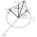
한편, 도 4는 본 발명의 제 4 실시예에 따른 압력 센서를 이용한 마우스 알고리즘 구현 방법을 설명하기 위한 도면으로서, 본 발명의 제 4 실시예를 도 4를 참조하여 설명하면 우선 도 4의 (a)에 도시된 바와 같이 네 개의 힘센서(A1, A2, A3, A4)로 이루어진 촉각센서 이용한다. 힘의 크기를 통해 접촉 지점의 힘 벡터 값을 산출하는 방식은 아래와 같다.Meanwhile, FIG. 4 is a view for explaining a method of implementing a mouse algorithm using a pressure sensor according to a fourth embodiment of the present invention. Referring to FIG. 4, a fourth embodiment of the present invention will be described with reference to FIG. As shown in Fig.4 , a tactile sensor consisting of four force sensors (A1 , A2 , A3 , A4 ) is used. The method of calculating the force vector value of the contact point through the magnitude of the force is as follows.
우선, 4개의 센서에 대한 힘의 크기를 갖는 힘 벡타는 제 1 센서는 F1, 제 2센서는 F2, 제 3센서는 F3 그리고 제 4센서는 F4를 갖는다. 본 실시예에서는 제 2센서의 힘의 크기가 가장 크고 다음으로 제 1센서 힘의 크기이다.First, a force vector having a magnitude of force for four sensors has a first sensor F1 , a second sensor F2 , a third sensor F3, and a fourth sensor F4 . In this embodiment, the magnitude of the force of the second sensor is the largest and next is the magnitude of the first sensor force.
이어서, 도 4(b)를 참조하면, 제 1 센서의 벡터 ΔF1과 상기 제 2 센서의 벡 터 ΔF2의 각각 크기 성분(|F1-F3|, |F2-F4|)을 계산한다. 이때, ΔF1는 각도 0°를 갖으며, ΔF2는 각도 90°를 갖는다.Then, Fig. 4 (b) With reference to the first sensor vector ΔF1 and ΔF of the first vectors each size of thesecond component of the second sensor(| F 1 -F 3 |, | F 2 -F 4 |) of Calculate In this case, ΔF1 has an angle of 0 ° and ΔF2 has an angle of 90 °.
그리고, 벡터 ΔF1과 상기 벡터 ΔF2의 각도(0°, 90°) 및 크기 성분(|F1-F3|, |F2-F4|)을 이용하여 X축에 대한 각도 θmax 및 벡터 Fmax의 크기 |Fmax|를 계산한다.And the angle θmax with respect to the X axis using the angles (0 °, 90 °) and the magnitude components (| F1 -F3 |, | F2 -F4 |) of the vector ΔF1 and the vector ΔF2 . Calculate the size | Fmax | of the vector Fmax .
이때, 힘의 크기는

여기서,
이때, 접촉지점의 X축 방향은 Fmax의 X 성분으로서


또한, 본 발명의 제 1 실시예 내지 제 4 실시예에서는 압력 센서의 연속 접촉 감지를 통해 X 방향, Y 방향, Z 방향 및 회전 방향 궤적 이동을 감지하고, 다수의 압력 센서를 통해 검출되는 힘의 크기가 임펄스 신호 일 경우 또는 검출된 Z 축 방향 크기가 기준 값 이상일 경우 클릭으로 인식하도록 한다.In addition, in the first to fourth embodiments of the present invention, the X-, Y-, Z-, and rotational-direction trajectory movements are detected through continuous contact sensing of the pressure sensor, and the force detected by the plurality of pressure sensors is measured. If the magnitude is an impulse signal or if the detected Z-axis magnitude is greater than or equal to the reference value, it is recognized as a click.
삭제delete
상기와 같이 클릭 인식 기능을 추가할 경우 기존 컴퓨터에서 마우스를 사용하는 것과 같이 본 촉각센서는 화면상에서의 파일을 열고 닫는 기능이 가능하다.As described above, when the click recognition function is added, the tactile sensor can open and close the file on the screen as in the case of using a mouse in an existing computer.
또는, 도 5에 도시된 바와 같이 네 개의 힘센서(A1, A2, A3, A4)로 외에 중앙에 제 5 센서 A5를 설치하여 이것을 클릭 인식 장치로 활용할 수 있다.Alternatively, as shown in FIG. 5, in addition to the four force sensors A1 , A2 , A3 , and A4 , a fifth sensor A5 may be installed at the center to be used as a click recognition device.
예를 들어, 제 5 센서의 클릭이 감지될 경우 클릭으로 인식하도록 하여 화면상에서 파일을 열거나 닫을 수 있도록 한다. 한편 제 5 센서를 클릭하고 제 2 센서 및 제 4센서 중 어느 하나를 누르면 해당 센서가 설정된 방향으로 스크롤 하도록 할 수 있다.For example, when a click of the fifth sensor is detected, the file is recognized as a click so that the file can be opened or closed on the screen. Meanwhile, when the fifth sensor is clicked and one of the second and fourth sensors is pressed, the corresponding sensor may be scrolled in the set direction.
또한, 3 차원 공간에서의 마우스 커서 이동이 필요할 경우 X, Y, 회전 이동은 도 4에 도시된 바와 같이 네 개의 힘센서를 이용하고, Z 방향의 커서 이동거리는 제 5센서의 힘 벡터 크기로 정의한다. 단 Z축의 방향은 한쪽 방향만 가능하다.In addition, when the mouse cursor movement in the three-dimensional space is required, X, Y, rotational movement is used by four force sensors as shown in Figure 4, the cursor movement distance in the Z direction is defined as the force vector size of the fifth sensor do. However, only one direction is possible in the direction of the Z axis.
또는, 도 6에 도시된 바와 같이 네 개의 힘센서(A1, A2, A3, A4)와 더불어 바 깥 쪽에 네 개의 힘센서(A5, A6, A7, A8)로 이루어진 촉각센서를 이용하여 X, Y, Z 방향 그리고 회전방향으로 마우스 커서를 이동하도록 한다. 또한 기존 마우스처럼 클릭 및 스크롤 기능이 가능하도록 한다.Alternatively, as shown in FIG. 6, four force sensors A5 , A6 , A7 , and A8 are formed on the outer side together with four force sensors A1 , A2 , A3 , and A4 . Use the tactile sensor to move the mouse cursor in the X, Y, Z and rotation directions. It also enables click and scroll functions just like a traditional mouse.
상기 제 1 내지 제 4 센서(A1, A2, A3, A4)는 도 5에 도시된 바와 같이 마우스 커서를 X, Y 방향 및 회전방향으로 이동시키는 센서로 사용할 수 있다. 그리고, 마우스 커서의 Z축 한쪽방향 및 이동거리는 제 6 센서로 그리고 Z축 다른쪽 방향 및 이동거리는 제 8 센서의 힘 벡터의 크기 및 방향으로 결정한다.As illustrated in FIG. 5, the first to fourth sensors A1 , A2 , A3 , and A4 may be used as sensors for moving the mouse cursor in the X, Y, and rotation directions. The Z axis one direction and the moving distance of the mouse cursor are determined by the sixth sensor, and the Z direction one direction and the moving distance are determined by the magnitude and direction of the force vector of the eighth sensor.
한편, 기존 마우스처럼 XY 평면상에서 커서를 움직이면서 클릭 기능 및 스크롤 기능을 수행할 경우 먼저 제 5 센서 내지 제 8센서 (A5, A6, A7, A8) 중 어느 하나를 클릭기능으로 지정하여 해당 센서에 대한 접촉이 감지되면 클릭 기능을 수행하도록 한다. 따라서 클릭인식을 통해 기존의 마우스처럼 화면상에서 파일을 열거나 닫을 수 있다.On the other hand, when performing the click function and the scroll function while moving the cursor on the XY plane like a conventional mouse, first designate any one of the fifth sensor to the eighth sensor (A5 , A6 , A7 , A8 ) as a click function. When a contact with the sensor is detected, the click function is performed. Therefore, click recognition allows you to open or close a file on the screen like a conventional mouse.
또한, 제 5 내지 제 8 센서 (A5, A6, A7, A8) 중에서 특정 센서를 클릭 인식 센서로 설정하여 해당 센서의 접촉이 감지되면 클릭 기능을 하도록 하고 해당 센서를 제외한 나머지 센서의 접촉이 감지되면 스크롤 기능을 수행하도록 한다. 예를 들어 제 5 센서 및 제 7 센서를 클릭인식으로 설정할 경우 제 6 센서와 제 8센서를 사용하여 기존 마우스의 스크롤 기능을 수행할 수 있다.In addition, by setting a specific sensor among the fifth to eighth sensors A5 , A6 , A7 , and A8 as a click recognition sensor, when a touch of the corresponding sensor is detected, a click function is performed. When a contact is detected, the scroll function is performed. For example, when the fifth sensor and the seventh sensor are set to click recognition, the scroll function of the existing mouse may be performed by using the sixth sensor and the eighth sensor.
도 1은 본 발명의 제 1 실시예에 따른 압력 센서를 이용한 마우스 알고리즘 구현 방법을 설명하기 위한 예시도.1 is an exemplary view for explaining a mouse algorithm implementation method using a pressure sensor according to a first embodiment of the present invention.
도 2는 본 발명의 제 2 실시예에 따른 압력 센서를 이용한 마우스 알고리즘 구현 방법을 설명하기 위한 예시도.Figure 2 is an exemplary view for explaining a mouse algorithm implementation method using a pressure sensor according to a second embodiment of the present invention.
도 3은 본 발명의 제 3 실시예에 따른 압력 센서를 이용한 마우스 알고리즘 구현 방법을 설명하기 위한 예시도.Figure 3 is an exemplary view for explaining a mouse algorithm implementation method using a pressure sensor according to a third embodiment of the present invention.
도 4는 본 발명의 제 4 실시예에 따른 압력 센서를 이용한 마우스 알고리즘 구현 방법을 설명하기 위한 예시도.Figure 4 is an exemplary view for explaining a mouse algorithm implementation method using a pressure sensor according to a fourth embodiment of the present invention.
도 5는 본 발명의 제 5 실시예에 따른 압력 센서를 이용한 마우스 알고리즘 구현 방법을 설명하기 위한 예시도.5 is an exemplary view for explaining a mouse algorithm implementation method using a pressure sensor according to a fifth embodiment of the present invention.
도 6는 본 발명의 제 실시예에 따른 압력 센서를 이용한 마우스 알고리즘 구현 방법을 설명하기 위한 예시도.6 is an exemplary view for explaining a mouse algorithm implementation method using a pressure sensor according to an embodiment of the present invention.
Claims (11)
Translated fromKoreanPriority Applications (3)
| Application Number | Priority Date | Filing Date | Title |
|---|---|---|---|
| KR1020070068237AKR100950234B1 (en) | 2007-07-06 | 2007-07-06 | Implementation method of mouse algorithm using pressure sensor |
| US12/667,983US20100149124A1 (en) | 2007-07-06 | 2007-08-03 | Method for implementing mouse algorithm using tactile sensor |
| PCT/KR2007/003742WO2009008568A1 (en) | 2007-07-06 | 2007-08-03 | Method for implementing mouse algorithm using tactile sensor |
Applications Claiming Priority (1)
| Application Number | Priority Date | Filing Date | Title |
|---|---|---|---|
| KR1020070068237AKR100950234B1 (en) | 2007-07-06 | 2007-07-06 | Implementation method of mouse algorithm using pressure sensor |
Publications (2)
| Publication Number | Publication Date |
|---|---|
| KR20090004211A KR20090004211A (en) | 2009-01-12 |
| KR100950234B1true KR100950234B1 (en) | 2010-03-29 |
Family
ID=40228727
Family Applications (1)
| Application Number | Title | Priority Date | Filing Date |
|---|---|---|---|
| KR1020070068237AExpired - Fee RelatedKR100950234B1 (en) | 2007-07-06 | 2007-07-06 | Implementation method of mouse algorithm using pressure sensor |
Country Status (3)
| Country | Link |
|---|---|
| US (1) | US20100149124A1 (en) |
| KR (1) | KR100950234B1 (en) |
| WO (1) | WO2009008568A1 (en) |
Cited By (1)
| Publication number | Priority date | Publication date | Assignee | Title |
|---|---|---|---|---|
| KR101795268B1 (en) | 2016-06-07 | 2017-11-07 | 현대자동차주식회사 | Touch input device and control method of the same |
Families Citing this family (27)
| Publication number | Priority date | Publication date | Assignee | Title |
|---|---|---|---|---|
| JP5173870B2 (en) | 2009-01-28 | 2013-04-03 | 京セラ株式会社 | Input device |
| JP4723656B2 (en)* | 2009-02-03 | 2011-07-13 | 京セラ株式会社 | Input device |
| US9740341B1 (en) | 2009-02-26 | 2017-08-22 | Amazon Technologies, Inc. | Capacitive sensing with interpolating force-sensitive resistor array |
| US10180746B1 (en) | 2009-02-26 | 2019-01-15 | Amazon Technologies, Inc. | Hardware enabled interpolating sensor and display |
| US9740340B1 (en) | 2009-07-31 | 2017-08-22 | Amazon Technologies, Inc. | Visually consistent arrays including conductive mesh |
| US9785272B1 (en) | 2009-07-31 | 2017-10-10 | Amazon Technologies, Inc. | Touch distinction |
| KR101115418B1 (en)* | 2009-11-09 | 2012-02-16 | 한국표준과학연구원 | 6-axis sensor structure using force sensor and method of measuring force and moment therewith |
| US8810524B1 (en) | 2009-11-20 | 2014-08-19 | Amazon Technologies, Inc. | Two-sided touch sensor |
| KR101739054B1 (en)* | 2010-09-08 | 2017-05-24 | 삼성전자주식회사 | Motion control method and apparatus in a device |
| US9870093B2 (en)* | 2010-11-23 | 2018-01-16 | Ge Aviation Systems Llc | System and method for improving touch screen display use under vibration and turbulence |
| US9417754B2 (en) | 2011-08-05 | 2016-08-16 | P4tents1, LLC | User interface system, method, and computer program product |
| KR101894951B1 (en) | 2011-09-20 | 2018-10-15 | 삼성전자주식회사 | Tactile sense feedback apparatus and method for operating tactile sense feedback apparatus |
| WO2013170099A1 (en) | 2012-05-09 | 2013-11-14 | Yknots Industries Llc | Calibration of haptic feedback systems for input devices |
| WO2013169299A1 (en) | 2012-05-09 | 2013-11-14 | Yknots Industries Llc | Haptic feedback based on input progression |
| WO2013188307A2 (en) | 2012-06-12 | 2013-12-19 | Yknots Industries Llc | Haptic electromagnetic actuator |
| US9886116B2 (en) | 2012-07-26 | 2018-02-06 | Apple Inc. | Gesture and touch input detection through force sensing |
| WO2014104726A1 (en)* | 2012-12-26 | 2014-07-03 | 전자부품연구원 | Method for providing user interface using one-point touch and apparatus for same |
| US9547378B2 (en) | 2013-03-07 | 2017-01-17 | Hewlett-Packard Development Company, L.P. | Sensor on side of computing device |
| KR102088339B1 (en)* | 2013-04-30 | 2020-03-12 | 인텔렉추얼디스커버리 주식회사 | Touch pad having force sensor and input method using the same |
| JP5824487B2 (en)* | 2013-08-09 | 2015-11-25 | レノボ・シンガポール・プライベート・リミテッド | Pointing device, keyboard assembly and portable computer. |
| CN105765504A (en)* | 2013-11-21 | 2016-07-13 | 3M创新有限公司 | Touch system and method employing force direction determination |
| US20150242037A1 (en) | 2014-01-13 | 2015-08-27 | Apple Inc. | Transparent force sensor with strain relief |
| US10297119B1 (en) | 2014-09-02 | 2019-05-21 | Apple Inc. | Feedback device in an electronic device |
| US9939901B2 (en) | 2014-09-30 | 2018-04-10 | Apple Inc. | Haptic feedback assembly |
| US9798409B1 (en)* | 2015-03-04 | 2017-10-24 | Apple Inc. | Multi-force input device |
| US10402042B2 (en)* | 2016-06-13 | 2019-09-03 | Lenovo (Singapore) Pte. Ltd. | Force vector cursor control |
| CN109782930B (en)* | 2019-01-17 | 2020-07-10 | 珠海恒宇新科技有限公司 | Control method of pressure speed mouse |
Citations (4)
| Publication number | Priority date | Publication date | Assignee | Title |
|---|---|---|---|---|
| JPH07114438A (en)* | 1993-10-18 | 1995-05-02 | Nec Corp | Pressure sensing type pointing device |
| JP2002182847A (en)* | 2000-12-12 | 2002-06-28 | Hitachi Ltd | Information processing device with touchpad |
| KR20060076293A (en)* | 2003-09-16 | 2006-07-04 | 가부시키가이샤 도쿄다이가쿠 티엘오 | Optical tactile sensor and method of reconstructing force vector distribution using the sensor |
| KR20060076292A (en)* | 2003-09-16 | 2006-07-04 | 가부시키가이샤 도쿄다이가쿠 티엘오 | Force vector reconstruction method using optical tactile sensor |
Family Cites Families (8)
| Publication number | Priority date | Publication date | Assignee | Title |
|---|---|---|---|---|
| JPS6211925A (en)* | 1985-07-09 | 1987-01-20 | Nec Corp | Pressure sensor mouse |
| FR2675285B1 (en)* | 1991-04-11 | 1993-07-16 | Archos | TOUCHSCREEN. |
| US6025832A (en)* | 1995-09-29 | 2000-02-15 | Kabushiki Kaisha Toshiba | Signal generating apparatus, signal inputting apparatus and force-electricity transducing apparatus |
| JP3191284B2 (en)* | 1998-06-23 | 2001-07-23 | 日本電気株式会社 | Character input device |
| JP2000047811A (en)* | 1998-07-27 | 2000-02-18 | Alps Electric Co Ltd | Input device |
| KR100855603B1 (en)* | 2005-03-18 | 2008-09-01 | 전자부품연구원 | Tactile sensor and manufacturing method |
| KR100740669B1 (en)* | 2005-08-11 | 2007-07-18 | 한국표준과학연구원 | Signal processing device for tactile sensor composed of 3 axis force sensors |
| KR101016221B1 (en)* | 2008-11-14 | 2011-02-25 | 한국표준과학연구원 | Implementation of Algorithm for Processing Touch Input on Input Module with Force Sensor |
- 2007
- 2007-07-06KRKR1020070068237Apatent/KR100950234B1/ennot_activeExpired - Fee Related
- 2007-08-03USUS12/667,983patent/US20100149124A1/ennot_activeAbandoned
- 2007-08-03WOPCT/KR2007/003742patent/WO2009008568A1/enactiveApplication Filing
Patent Citations (4)
| Publication number | Priority date | Publication date | Assignee | Title |
|---|---|---|---|---|
| JPH07114438A (en)* | 1993-10-18 | 1995-05-02 | Nec Corp | Pressure sensing type pointing device |
| JP2002182847A (en)* | 2000-12-12 | 2002-06-28 | Hitachi Ltd | Information processing device with touchpad |
| KR20060076293A (en)* | 2003-09-16 | 2006-07-04 | 가부시키가이샤 도쿄다이가쿠 티엘오 | Optical tactile sensor and method of reconstructing force vector distribution using the sensor |
| KR20060076292A (en)* | 2003-09-16 | 2006-07-04 | 가부시키가이샤 도쿄다이가쿠 티엘오 | Force vector reconstruction method using optical tactile sensor |
Cited By (1)
| Publication number | Priority date | Publication date | Assignee | Title |
|---|---|---|---|---|
| KR101795268B1 (en) | 2016-06-07 | 2017-11-07 | 현대자동차주식회사 | Touch input device and control method of the same |
Also Published As
| Publication number | Publication date |
|---|---|
| WO2009008568A1 (en) | 2009-01-15 |
| US20100149124A1 (en) | 2010-06-17 |
| KR20090004211A (en) | 2009-01-12 |
Similar Documents
| Publication | Publication Date | Title |
|---|---|---|
| KR100950234B1 (en) | Implementation method of mouse algorithm using pressure sensor | |
| JP4743267B2 (en) | Information processing apparatus, information processing method, and program | |
| US6677927B1 (en) | X-Y navigation input device | |
| US20120120002A1 (en) | System and method for display proximity based control of a touch screen user interface | |
| KR101749956B1 (en) | Computer keyboard with integrated an electrode arrangement | |
| EP1727028B1 (en) | Dual-positioning controller and method for controlling an indicium on a display of an electronic device | |
| US20100177053A2 (en) | Method and apparatus for control of multiple degrees of freedom of a display | |
| KR100934767B1 (en) | Slim mouse for mobile device and manufacturing method thereof | |
| US20080231601A1 (en) | Input device for continuous gesturing within a user interface | |
| CA2937956A1 (en) | In-air ultrasound pen gestures | |
| WO2007121676A1 (en) | Method and device for controlling information display output and input device | |
| KR100936046B1 (en) | Implementation method of touch pad with mouse function using tactile sensor | |
| KR101124818B1 (en) | Input device and pointing device | |
| TWI413916B (en) | Touch sensor track point and methods | |
| JPWO2012111227A1 (en) | Touch-type input device, electronic apparatus, and input method | |
| KR100664963B1 (en) | Slide type input device, portable device having same and input method | |
| CN103257724B (en) | A kind of non-contact type mouse and method of operating thereof | |
| EP1973029B1 (en) | Input device for continuous gesturing within a user interface | |
| US20090153484A1 (en) | Mouse and method for cursor control | |
| CN105278780B (en) | Capacitive finger navigation device with hybrid mode and operation method thereof | |
| KR101065921B1 (en) | Pointing method using touch sensor and pointing device using the same | |
| JP5992380B2 (en) | Pointing device, notebook personal computer, and operation method. | |
| KR101598579B1 (en) | User interface and method for providing guidance information | |
| CN102298484B (en) | Portable electronic device and control method of software object thereof | |
| KR101095923B1 (en) | Cursor input device of portable terminal |
Legal Events
| Date | Code | Title | Description |
|---|---|---|---|
| A201 | Request for examination | ||
| PA0109 | Patent application | St.27 status event code:A-0-1-A10-A12-nap-PA0109 | |
| PA0201 | Request for examination | St.27 status event code:A-1-2-D10-D11-exm-PA0201 | |
| D13-X000 | Search requested | St.27 status event code:A-1-2-D10-D13-srh-X000 | |
| D14-X000 | Search report completed | St.27 status event code:A-1-2-D10-D14-srh-X000 | |
| E902 | Notification of reason for refusal | ||
| PE0902 | Notice of grounds for rejection | St.27 status event code:A-1-2-D10-D21-exm-PE0902 | |
| PG1501 | Laying open of application | St.27 status event code:A-1-1-Q10-Q12-nap-PG1501 | |
| T11-X000 | Administrative time limit extension requested | St.27 status event code:U-3-3-T10-T11-oth-X000 | |
| E13-X000 | Pre-grant limitation requested | St.27 status event code:A-2-3-E10-E13-lim-X000 | |
| P11-X000 | Amendment of application requested | St.27 status event code:A-2-2-P10-P11-nap-X000 | |
| P13-X000 | Application amended | St.27 status event code:A-2-2-P10-P13-nap-X000 | |
| E90F | Notification of reason for final refusal | ||
| PE0902 | Notice of grounds for rejection | St.27 status event code:A-1-2-D10-D21-exm-PE0902 | |
| P11-X000 | Amendment of application requested | St.27 status event code:A-2-2-P10-P11-nap-X000 | |
| P13-X000 | Application amended | St.27 status event code:A-2-2-P10-P13-nap-X000 | |
| E902 | Notification of reason for refusal | ||
| PE0902 | Notice of grounds for rejection | St.27 status event code:A-1-2-D10-D21-exm-PE0902 | |
| E13-X000 | Pre-grant limitation requested | St.27 status event code:A-2-3-E10-E13-lim-X000 | |
| P11-X000 | Amendment of application requested | St.27 status event code:A-2-2-P10-P11-nap-X000 | |
| P13-X000 | Application amended | St.27 status event code:A-2-2-P10-P13-nap-X000 | |
| E701 | Decision to grant or registration of patent right | ||
| PE0701 | Decision of registration | St.27 status event code:A-1-2-D10-D22-exm-PE0701 | |
| GRNT | Written decision to grant | ||
| PR0701 | Registration of establishment | St.27 status event code:A-2-4-F10-F11-exm-PR0701 | |
| PR1002 | Payment of registration fee | Fee payment year number:1 St.27 status event code:A-2-2-U10-U11-oth-PR1002 | |
| PG1601 | Publication of registration | St.27 status event code:A-4-4-Q10-Q13-nap-PG1601 | |
| P22-X000 | Classification modified | St.27 status event code:A-4-4-P10-P22-nap-X000 | |
| FPAY | Annual fee payment | Payment date:20130207 Year of fee payment:4 | |
| PR1001 | Payment of annual fee | Fee payment year number:4 St.27 status event code:A-4-4-U10-U11-oth-PR1001 | |
| R18-X000 | Changes to party contact information recorded | St.27 status event code:A-5-5-R10-R18-oth-X000 | |
| LAPS | Lapse due to unpaid annual fee | ||
| PC1903 | Unpaid annual fee | Not in force date:20140324 Payment event data comment text:Termination Category : DEFAULT_OF_REGISTRATION_FEE St.27 status event code:A-4-4-U10-U13-oth-PC1903 | |
| PC1903 | Unpaid annual fee | Ip right cessation event data comment text:Termination Category : DEFAULT_OF_REGISTRATION_FEE Not in force date:20140324 St.27 status event code:N-4-6-H10-H13-oth-PC1903 | |
| PN2301 | Change of applicant | St.27 status event code:A-5-5-R10-R11-asn-PN2301 St.27 status event code:A-5-5-R10-R13-asn-PN2301 | |
| R18-X000 | Changes to party contact information recorded | St.27 status event code:A-5-5-R10-R18-oth-X000 | |
| R18-X000 | Changes to party contact information recorded | St.27 status event code:A-5-5-R10-R18-oth-X000 | |
| R18-X000 | Changes to party contact information recorded | St.27 status event code:A-5-5-R10-R18-oth-X000 |