KR100949976B1 - A method and apparatus for decoding/encoding a video signal - Google Patents
A method and apparatus for decoding/encoding a video signalDownload PDFInfo
- Publication number
- KR100949976B1 KR100949976B1KR1020097017180AKR20097017180AKR100949976B1KR 100949976 B1KR100949976 B1KR 100949976B1KR 1020097017180 AKR1020097017180 AKR 1020097017180AKR 20097017180 AKR20097017180 AKR 20097017180AKR 100949976 B1KR100949976 B1KR 100949976B1
- Authority
- KR
- South Korea
- Prior art keywords
- view
- prediction
- reference picture
- inter
- picture
- Prior art date
- Legal status (The legal status is an assumption and is not a legal conclusion. Google has not performed a legal analysis and makes no representation as to the accuracy of the status listed.)
- Expired - Fee Related
Links
Images


Classifications
- H—ELECTRICITY
- H04—ELECTRIC COMMUNICATION TECHNIQUE
- H04N—PICTORIAL COMMUNICATION, e.g. TELEVISION
- H04N19/00—Methods or arrangements for coding, decoding, compressing or decompressing digital video signals
- H04N19/10—Methods or arrangements for coding, decoding, compressing or decompressing digital video signals using adaptive coding
- H04N19/102—Methods or arrangements for coding, decoding, compressing or decompressing digital video signals using adaptive coding characterised by the element, parameter or selection affected or controlled by the adaptive coding
- H04N19/103—Selection of coding mode or of prediction mode
- H04N19/105—Selection of the reference unit for prediction within a chosen coding or prediction mode, e.g. adaptive choice of position and number of pixels used for prediction
- H—ELECTRICITY
- H04—ELECTRIC COMMUNICATION TECHNIQUE
- H04N—PICTORIAL COMMUNICATION, e.g. TELEVISION
- H04N19/00—Methods or arrangements for coding, decoding, compressing or decompressing digital video signals
- H04N19/50—Methods or arrangements for coding, decoding, compressing or decompressing digital video signals using predictive coding
- H04N19/503—Methods or arrangements for coding, decoding, compressing or decompressing digital video signals using predictive coding involving temporal prediction
- H04N19/51—Motion estimation or motion compensation
- H04N19/573—Motion compensation with multiple frame prediction using two or more reference frames in a given prediction direction
- H—ELECTRICITY
- H04—ELECTRIC COMMUNICATION TECHNIQUE
- H04N—PICTORIAL COMMUNICATION, e.g. TELEVISION
- H04N19/00—Methods or arrangements for coding, decoding, compressing or decompressing digital video signals
- H04N19/50—Methods or arrangements for coding, decoding, compressing or decompressing digital video signals using predictive coding
- H04N19/503—Methods or arrangements for coding, decoding, compressing or decompressing digital video signals using predictive coding involving temporal prediction
- H04N19/51—Motion estimation or motion compensation
- H—ELECTRICITY
- H04—ELECTRIC COMMUNICATION TECHNIQUE
- H04N—PICTORIAL COMMUNICATION, e.g. TELEVISION
- H04N19/00—Methods or arrangements for coding, decoding, compressing or decompressing digital video signals
- H04N19/50—Methods or arrangements for coding, decoding, compressing or decompressing digital video signals using predictive coding
- H04N19/597—Methods or arrangements for coding, decoding, compressing or decompressing digital video signals using predictive coding specially adapted for multi-view video sequence encoding
- H—ELECTRICITY
- H04—ELECTRIC COMMUNICATION TECHNIQUE
- H04N—PICTORIAL COMMUNICATION, e.g. TELEVISION
- H04N19/00—Methods or arrangements for coding, decoding, compressing or decompressing digital video signals
- H04N19/70—Methods or arrangements for coding, decoding, compressing or decompressing digital video signals characterised by syntax aspects related to video coding, e.g. related to compression standards
- H—ELECTRICITY
- H04—ELECTRIC COMMUNICATION TECHNIQUE
- H04N—PICTORIAL COMMUNICATION, e.g. TELEVISION
- H04N19/00—Methods or arrangements for coding, decoding, compressing or decompressing digital video signals
- H04N19/10—Methods or arrangements for coding, decoding, compressing or decompressing digital video signals using adaptive coding
- H04N19/169—Methods or arrangements for coding, decoding, compressing or decompressing digital video signals using adaptive coding characterised by the coding unit, i.e. the structural portion or semantic portion of the video signal being the object or the subject of the adaptive coding
- H04N19/17—Methods or arrangements for coding, decoding, compressing or decompressing digital video signals using adaptive coding characterised by the coding unit, i.e. the structural portion or semantic portion of the video signal being the object or the subject of the adaptive coding the unit being an image region, e.g. an object
- H04N19/176—Methods or arrangements for coding, decoding, compressing or decompressing digital video signals using adaptive coding characterised by the coding unit, i.e. the structural portion or semantic portion of the video signal being the object or the subject of the adaptive coding the unit being an image region, e.g. an object the region being a block, e.g. a macroblock
- H—ELECTRICITY
- H04—ELECTRIC COMMUNICATION TECHNIQUE
- H04N—PICTORIAL COMMUNICATION, e.g. TELEVISION
- H04N19/00—Methods or arrangements for coding, decoding, compressing or decompressing digital video signals
- H04N19/60—Methods or arrangements for coding, decoding, compressing or decompressing digital video signals using transform coding
- H04N19/61—Methods or arrangements for coding, decoding, compressing or decompressing digital video signals using transform coding in combination with predictive coding
Landscapes
- Engineering & Computer Science (AREA)
- Multimedia (AREA)
- Signal Processing (AREA)
- Compression Or Coding Systems Of Tv Signals (AREA)
- Testing, Inspecting, Measuring Of Stereoscopic Televisions And Televisions (AREA)
Abstract
Translated fromKorean
Description
Translated fromKorean본 발명은 비디오 신호의 코딩에 관한 기술이다.The present invention relates to the coding of video signals.
압축 부호화란 디지털화한 정보를 통신 회선을 통해 전송하거나, 저장 매체에 적합한 형태로 저장하는 일련의 신호 처리 기술을 의미한다. 압축 부호화의 대상에는 음성, 영상, 문자 등의 대상이 존재하며, 특히 영상을 대상으로 압축 부호화를 수행하는 기술을 비디오 영상 압축이라고 일컫는다. 비디오 영상의 일반적인 특징은 공간적 중복성, 시간적 중복성을 지니고 있는 점에 특징이 있다.Compression coding refers to a series of signal processing techniques that transmit digitized information through a communication line or store the data in a form suitable for a storage medium. The object of compression encoding includes objects such as voice, video, text, and the like. In particular, a technique of performing compression encoding on an image is called video image compression. The general feature of the video image is that it has spatial redundancy and temporal redundancy.
본 발명의 목적은 비디오 신호의 코딩 효율을 높이고자 함에 있다.An object of the present invention is to improve the coding efficiency of a video signal.
블록 간 또는 시점 간의 상관관계를 이용하여 비디오 신호의 코딩 효율을 높이고자 한다.The coding efficiency of a video signal is improved by using correlations between blocks or views.
픽쳐의 시점을 식별할 수 있는 시점 정보를 정의함으로써 비디오 신호를 효율적으로 코딩하고자 한다.It is intended to efficiently code a video signal by defining viewpoint information that can identify a viewpoint of a picture.
시점간 예측에 이용되는 참조 픽쳐들을 관리하기 위한 방법을 제공함으로써 비디오 신호를 효율적으로 코딩하고자 한다.It is intended to efficiently code a video signal by providing a method for managing reference pictures used for inter-view prediction.
시점간 예측을 위한 참조 픽쳐 리스트를 생성하는 방법을 제공함으로써 비디오 신호를 효율적으로 코딩하고자 한다.It is intended to efficiently code a video signal by providing a method of generating a reference picture list for inter-view prediction.
시점간 예측을 위한 참조 픽쳐 리스트를 재배열하는 방법을 제공함으로써 비디오 신호를 효율적으로 코딩하고자 한다.The present invention seeks to efficiently code a video signal by providing a method of rearranging a reference picture list for inter-view prediction.
인터뷰 픽쳐 그룹 식별 정보를 규격화된 방식으로 추가함으로써 비디오 신호의 랜덤 액세스를 효율적으로 수행하고자 한다.By adding the interview picture group identification information in a standardized manner, the random access of the video signal is efficiently performed.
인터뷰 픽쳐 그룹과 넌-인터 뷰 픽쳐 그룹을 정의함으로써 랜덤 액세스 및 시점간 예측을 보다 효율적으로 수행하고자 한다.By defining an interview picture group and a non-interview picture group, it is intended to perform random access and inter-view prediction more efficiently.
인터뷰 픽쳐 그룹 식별 정보를 이용함으로써 시점간 예측을 보다 효율적으로 수행하고자 한다.Interview prediction is more efficiently performed by using the interview picture group identification information.
인터뷰 픽쳐 그룹 식별 정보를 이용함으로써 시점간 예측을 위한 참조 픽쳐 들을 보다 효율적으로 관리하고자 한다.By using the interview picture group identification information, reference pictures for inter-view prediction are more efficiently managed.
상기 목적을 달성하기 위하여 본 발명은, 랜덤 액세스 픽쳐를 포함하는 다시점 비디오 데이터 스트림을 수신하는 단계, 여기서 상기 랜덤 액세스 픽쳐는 랜덤 액세스 슬라이스를 포함하고, 상기 랜덤 액세스 슬라이스는 상기 랜덤 액세스 픽쳐와 동일 시간 및 다른 시점에 대응되는 슬라이스만을 참조함; 상기 랜덤 액세스 슬라이스를 위한 참조 픽쳐 리스트의 초기화 정보를 포함하는 상기 다시점 비디오 데이터 스트림을 나타내는 식별 정보를 획득하는 단계; 상기 식별 정보에 기초하여 상기 랜덤 액세스 슬라이스의 참조 픽쳐 리스트의 초기화 정보를 획득하는 단계, 여기서 상기 초기화 정보는 복수개의 시점들 사이의 참조 관계를 나타내고, 상기 초기화 정보는 상기 복수개의 시점들의 시점 개수 정보와 시점 식별 정보를 포함함; 상기 시점 개수 정보와 상기 시점 식별 정보를 이용하여 상기 랜덤 액세스 슬라이스의 참조 픽쳐 리스트를 초기화하는 단계; 상기 다시점 비디오 데이터 스트림으로부터 시점간 참조 인덱스의 차이값을 획득하는 단계, 여기서 상기 시점간 참조 인덱스의 차이값은 상기 초기화된 참조 픽쳐 리스트 내에서 시점간 참조 인덱스의 변경을 위한 차이값을 나타냄; 상기 차이값에 따라, 상기 초기화된 참조 픽쳐 리스트 내에서 상기 시점간 참조 인덱스를 변경하기 위한 할당 변경 값을 결정하는 단계; 상기 결정된 할당 변경 값을 이용하여 상기 초기화된 참조 픽쳐 리스트를 변경하는 단계; 상기 변경된 참조 픽쳐 리스트에 기초하여 상기 랜덤 액세스 슬라이스 내에 있는 매크로블록의 예측값을 결정하는 단계; 및 상기 예측값을 이용하여 상기 매크로블록을 디코딩하는 단계를 포함하되, 상기 초기화 정보는 시퀀스의 확장 영역으로부터 획득되는 것을 특징으로 하는 다시점 비디오 데이터를 디코딩하는 방법을 제공한다.In order to achieve the above object, the present invention provides a method comprising the steps of: receiving a multiview video data stream comprising a random access picture, wherein the random access picture comprises a random access slice, the random access slice being the same as the random access picture Refer only to slices corresponding to time and other time points; Obtaining identification information representing the multi-view video data stream including initialization information of a reference picture list for the random access slice; Acquiring initialization information of a reference picture list of the random access slice based on the identification information, wherein the initialization information indicates a reference relationship between a plurality of viewpoints, and the initialization information indicates the number of viewpoints of the plurality of viewpoints. And point of view identification information; Initializing a reference picture list of the random access slice using the viewpoint number information and the viewpoint identification information; Obtaining a difference value of the inter-view reference index from the multi-view video data stream, wherein the difference value of the inter-view reference index indicates a difference value for changing the inter-view reference index in the initialized reference picture list; Determining an allocation change value for changing the inter-view reference index in the initialized reference picture list according to the difference value; Changing the initialized reference picture list using the determined allocation change value; Determining a predicted value of a macroblock within the random access slice based on the modified reference picture list; And decoding the macroblock using the prediction value, wherein the initialization information is obtained from an extended region of a sequence.
또한, 본 발명은, 랜덤 액세스 픽쳐를 포함하는 다시점 비디오 데이터 스트림을 수신하고, 랜덤 액세스 슬라이스를 위한 참조 픽쳐 리스트의 초기화 정보를 포함하는 상기 다시점 비디오 데이터 스트림을 나타내는 식별 정보를 획득하고, 상기 식별 정보에 기초하여 상기 랜덤 액세스 슬라이스의 참조 픽쳐 리스트의 초기화 정보를 획득하는 NAL 파싱부, 여기서 상기 랜덤 액세스 픽쳐는 상기 랜덤 액세스 슬라이스를 포함하고, 상기 랜덤 액세스 슬라이스는 상기 랜덤 액세스 픽쳐와 동일 시간 및 다른 시점에 대응되는 슬라이스만을 참조하고, 상기 초기화 정보는 복수개의 시점들 사이의 참조 관계를 나타내고, 상기 초기화 정보는 상기 복수개의 시점들의 시점 개수 정보와 시점 식별 정보를 포함함; 상기 시점 개수 정보와 상기 시점 식별 정보를 이용하여 상기 랜덤 액세스 슬라이스의 참조 픽쳐 리스트를 초기화하고, 상기 다시점 비디오 데이터 스트림으로부터 시점간 참조 인덱스의 차이값을 획득하고, 상기 차이값에 따라 상기 초기화된 참조 픽쳐 리스트 내에서 상기 시점간 참조 인덱스를 변경하기 위한 할당 변경 값을 결정하고, 상기 결정된 할당 변경 값을 이용하여 상기 초기화된 참조 픽쳐 리스트를 변경하는 복호 픽쳐 버퍼부, 여기서 상기 시점간 참조 인덱스의 차이값은 상기 초기화된 참조 픽쳐 리스트 내에서 시점간 참조 인덱스의 변경을 위한 차이값을 나타냄; 및 상기 변경된 참조 픽쳐 리스트에 기초하여 상기 랜덤 액세스 슬라이스 내에 있는 매크로블록의 예측값을 결 정하고, 상기 예측값을 이용하여 상기 매크로블록을 디코딩하는 인터 예측부를 포함하되, 상기 초기화 정보는 시퀀스의 확장 영역으로부터 획득되는 것을 특징으로 하는 다시점 비디오 데이터를 디코딩하는 장치를 제공한다.The present invention also provides a multi-view video data stream including a random access picture, obtains identification information indicating the multi-view video data stream including initialization information of a reference picture list for the random access slice, A NAL parsing unit obtaining initialization information of a reference picture list of the random access slice based on identification information, wherein the random access picture includes the random access slice, wherein the random access slice is the same time as the random access picture and Refers only to slices corresponding to different viewpoints, wherein the initialization information indicates a reference relationship between a plurality of viewpoints, and the initialization information includes view number information and viewpoint identification information of the plurality of viewpoints; The reference picture list of the random access slice is initialized using the view number information and the view identification information, a difference value of an inter-view reference index is obtained from the multi-view video data stream, and the initialized according to the difference value. A decoded picture buffer unit configured to determine an allocation change value for changing the inter-view reference index in a reference picture list and to change the initialized reference picture list using the determined allocation change value, wherein the decoded picture buffer unit The difference value represents a difference value for changing the inter-view reference index in the initialized reference picture list; And an inter predictor configured to determine a predicted value of a macroblock in the random access slice based on the changed reference picture list, and to decode the macroblock using the predicted value, wherein the initialization information is obtained from an extended region of a sequence. An apparatus for decoding multi-view video data, characterized in that the.
또한, 본 발명에서, 상기 시점 개수 정보는 상기 랜덤 액세스 픽쳐의 참조 시점의 개수를 나타내고, 상기 시점 식별 정보는 상기 랜덤 액세스 픽쳐의 참조 시점의 시점 식별자를 나타내는 것을 특징으로 한다.In the present invention, the number of viewpoint information indicates the number of reference viewpoints of the random access picture, and the viewpoint identification information indicates a viewpoint identifier of the reference viewpoint of the random access picture.
또한, 본 발명에서, 상기 다시점 비디오 데이터는 다른 시점들과는 독립적인 기준 시점의 비디오 데이터를 포함하고, 상기 기준 시점은 시점간 예측을 이용하지 않고 디코딩 가능한 시점인 것을 특징으로 한다.In the present invention, the multi-view video data includes video data of a reference view independent from other views, and the reference view is a view that can be decoded without using inter-view prediction.
또한, 본 발명에서, 상기 식별 정보는 NAL 유닛 타입에 기초하여 획득되고, 이때 상기 NAL 유닛 타입은 상기 다시점 비디오 데이터의 시퀀스 정보를 나타내는 것을 특징으로 한다.Also, in the present invention, the identification information is obtained based on the NAL unit type, wherein the NAL unit type indicates sequence information of the multi-view video data.
또한, 본 발명에서, 상기 차이값은 슬라이스 헤더로부터 획득되는 것을 특징으로 한다.In the present invention, the difference value is characterized in that is obtained from the slice header.
또한, 본 발명에서, 상기 결정된 할당 변경 값은 상기 초기화된 참조 픽쳐 리스트 내에 있는 랜덤 액세스 픽쳐에 시점간 참조 인덱스를 할당하기 위해 이용되는 것을 특징으로 한다.Further, in the present invention, the determined allocation change value is used to assign an inter-view reference index to a random access picture in the initialized reference picture list.
또한, 본 발명에서, 상기 할당 변경 값은 상기 초기화된 참조 픽쳐 리스트 내에 있는 시점간 참조 픽쳐의 시점 식별자와 관련된 변수를 나타내는 것을 특징으로 한다.Also, in the present invention, the allocation change value may be a variable related to a viewpoint identifier of an inter-view reference picture in the initialized reference picture list.
또한, 본 발명에서, 상기 초기화된 참조 픽쳐 리스트 내에서 변경되는 픽쳐 외의 나머지 픽쳐들의 위치는 참조 픽쳐 리스트의 뒤쪽으로 옮겨지는 것을 특징으로 한다.In addition, in the present invention, the positions of the remaining pictures other than the changed picture in the initialized reference picture list may be moved to the rear of the reference picture list.
본 발명은 비디오 신호를 코딩함에 있어서, 다시점 비디오 영상의 전반적인 코딩 구조에 따를 때, 인터 뷰 픽쳐 그룹과 넌-인터 뷰 픽쳐 그룹의 참조 정보가 다르기 때문에 상기 인터 뷰 픽쳐 그룹 식별 정보에 따라 인터 뷰 픽쳐 그룹과 넌-인터 뷰 픽쳐 그룹을 구별하여 코딩하게 될 경우 보다 효율적인 코딩이 가능할 수 있다. 또한, 인터 뷰 픽쳐 그룹과 넌-인터 뷰 픽쳐 그룹을 구별하여 참조 픽쳐 리스트를 관리함으로써 보다 효율적인 시점간 예측을 수행할 수 있다.According to the present invention, when the video signal is coded, the reference information of the inter-view picture group and the non-inter-view picture group is different according to the overall coding structure of the multi-view video image, so that the inter-view according to the inter-view picture group identification information. If coding is performed by distinguishing the picture group from the non-inter view picture group, more efficient coding may be possible. In addition, more efficient inter-view prediction may be performed by managing the reference picture list by distinguishing the inter view picture group from the non-inter view picture group.
또한, 시점간 예측에 이용되는 참조 픽쳐들을 관리하기 위한 방법을 제공함으로써 보다 효율적으로 코딩을 수행할 수 있게 된다. 또한, 시점간 예측을 위한 참조 픽쳐 리스트를 초기화하는 방법 및 재배열하는 방법을 제공함으로써 보다 효율적으로 코딩을 수행할 수 있게 된다. 본 발명을 이용하여 시점간 예측(inter-view prediction)을 수행할 때, DPB(Decoded Picture Buffer)의 부담을 감소시켜 코딩 속도를 향상시킬 수 있을 뿐만 아니라 보다 정확한 예측이 가능하여 전송할 비트수를 감소시킬 수도 있다.In addition, by providing a method for managing reference pictures used for inter-view prediction, coding can be performed more efficiently. In addition, by providing a method of initializing and rearranging a reference picture list for inter-view prediction, coding can be performed more efficiently. When performing inter-view prediction using the present invention, the coding speed can be improved by reducing the burden of a decoded picture buffer (DPB), and more accurate prediction can be performed, thereby reducing the number of bits to be transmitted. You can also
비디오 신호 데이터를 압축 부호화하는 기술은 공간적 중복성, 시간적 중복성, 스케일러블한 중복성, 시점간 존재하는 중복성을 고려하고 있다. 또한, 이러한 압축 부호화 과정에서 시점 간 존재하는 상호 중복성을 고려하여 압축 코딩을 할 수 있다. 시점간 중복성을 고려하는 압축 코딩에 대한 기술은 본 발명의 실시예일 뿐이며, 본 발명의 기술적 사상은 시간적 중복성, 스케일러블한 중복성 등에도 적용될 수 있다.The compression coding technique of video signal data considers spatial redundancy, temporal redundancy, scalable redundancy, and redundancy existing between views. In this compression encoding process, compression coding may be performed in consideration of mutual redundancy existing between views. The compression coding technique considering the inter-view redundancy is only an embodiment of the present invention, and the technical idea of the present invention may be applied to temporal redundancy, scalable redundancy, and the like.
비디오 신호의 비트열 구성을 살펴보면, 동영상 부호화 처리 그 자체를 다루는 VCL(Video Coding Layer, 비디오 부호화 계층)과 부호화된 정보를 전송하고 저장하는 하위 시스템과의 사이에 있는 NAL(Network Abstraction Layer, 네트워크 추상 계층)이라는 분리된 계층 구조로 정의되어 있다. 부호화 과정의 출력은 VCL 데이터이고 전송하거나 저장하기 전에 NAL 단위로 맵핑된다. 각 NAL 단위는 압축된 비디오 데이터 또는 헤더 정보에 해당하는 데이터인 RBSP(Raw Byte Sequence Payload, 동영상 압축의 결과데이터)를 포함한다.Looking at the bit string structure of the video signal, the Network Abstraction Layer (NAL) between the Video Coding Layer (VCL), which handles the video encoding process itself, and a subsystem for transmitting and storing coded information. Hierarchical structure). The output of the encoding process is VCL data and is mapped in units of NAL before transmission or storage. Each NAL unit includes raw video sequence payload (RBSP), which is data corresponding to compressed video data or header information.
NAL 단위는 기본적으로 NAL헤더와 RBSP의 두 부분으로 구성된다. NAL 헤더에는 그 NAL 단위의 참조픽처가 되는 슬라이스가 포함되어 있는지 여부를 나타내는 플래그 정보(nal_ref_idc)와 NAL 단위의 종류를 나타내는 식별자(nal_unit_type)가 포함되어 있다. RBSP 에는 압축된 원본의 데이터를 저장하며, RBSP 의 길이를 8비트의 배수로 표현하기 위해 RBSP 의 마지막에 RBSP 채워넣기 비트(RBSP trailing bit)를 첨가한다. 이러한 NAL 단위의 종류에는 IDR (Instantaneous Decoding Refresh, 순간 복호 리프레쉬) 픽쳐, SPS (Sequence Parameter Set, 시퀀스 파라미터 세트), PPS (Picture Parameter Set, 픽쳐 파라미터 세트), SEI (Supplemental Enhancement Information, 보충적 부가정보) 등이 있다.The NAL unit basically consists of two parts: the NAL header and the RBSP. The NAL header includes flag information (nal_ref_idc) indicating whether a slice serving as a reference picture of the NAL unit is included and an identifier (nal_unit_type) indicating the type of the NAL unit. The RBSP stores the compressed original data and adds an RBSP trailing bit at the end of the RBSP to express the length of the RBSP in multiples of 8 bits. These NAL unit types include Instantaneous Decoding Refresh (IDR) pictures, Sequence Parameter Set (SPS), Picture Parameter Set (PPS), and Supplemental Enhancement Information (SEI). Etc.
또한, 규격에서는 대상 제품을 적당한 비용으로 구현 가능하도록 여러 가지 프로파일 및 레벨로 제약하고 있는데, 복호기는 해당 프로파일과 레벨에서 정해진 제약을 만족시켜야 한다. 이처럼 복호기가 어떤 압축 영상의 범위까지 대응할 수 있는지 그 기능 또는 파라미터를 나타내기 위해 프로파일과 레벨이라는 두 가지의 개념이 정의되었다. 비트스트림이 어떤 프로파일에 기초하는 것인가는 프로파일 식별자(profile_idc)로 식별할 수 있다. 프로파일 식별자란, 비트스트림이 기반을 둔 프로파일을 나타내는 플래그를 의미한다. 예를 들어, H.264/AVC 에서는 프로파일 식별자가 66 이면 베이스라인 프로파일에 기초함을 의미하고, 77 이면 메인 프로파일에 기초함을 의미하며, 88 이면 확장 프로파일에 기초함을 의미한다. 상기 프로파일 식별자는 시퀀스 파라미터 세트에 포함될 수 있다.In addition, the specification restricts the product to various profiles and levels so that the target product can be implemented at a reasonable cost. The decoder must satisfy the constraints defined in the profile and level. As such, two concepts, profile and level, have been defined to represent the function or parameter of a compressed video range. Which profile the bitstream is based on may be identified by a profile identifier (profile_idc). The profile identifier means a flag indicating a profile on which the bitstream is based. For example, in H.264 / AVC, 66 means that the profile identifier is based on the baseline profile, 77 means that it is based on the main profile, and 88 means that it is based on the extended profile. The profile identifier may be included in a sequence parameter set.
따라서, 다시점(multiview) 영상을 다루기 위해서는 입력되는 비트스트림이 다시점 프로파일(Multiview Profile)에 대한 것인지 여부를 식별하고, 다시점 프로파일로 식별되면 다시점에 대한 하나 이상의 추가 정보를 전송할 수 있도록 신택스를 추가할 필요가 있다. 여기서 다시점 프로파일이란, H.264/AVC의 추가 기술로서 다시점 비디오(multiview video)를 다루는 프로파일 모드(profile mode)를 나타낸다. MVC는 기존 AVC 기술에 대한 추가 기술이므로 무조건적인 신택스보다는 MVC 모드인 경우에 대한 추가 정보로서 신택스를 추가하는 것이 더 효율적일 수 있다. 예를 들어, AVC의 프로파일 식별자가 다시점 프로파일을 나타낼 때 다시점 영상에 대한 정보를 추가하면 부호화 효율을 높일 수 있다.Therefore, in order to handle a multiview image, a syntax for identifying whether an input bitstream is for a multiview profile, and for transmitting one or more additional information about a multiview if identified as a multiview profile. You need to add The multiview profile here refers to a profile mode that handles multiview video as an additional technique of H.264 / AVC. Since MVC is an additional technology to the existing AVC technology, it may be more efficient to add syntax as additional information for the MVC mode than an unconditional syntax. For example, when the profile identifier of the AVC indicates a multi-view profile, adding information about the multi-view image may increase encoding efficiency.
시퀀스 파라미터 세트란, 프로파일, 레벨 등 시퀀스 전체의 부호화에 걸쳐있 는 정보가 포함되어 있는 헤더 정보를 말한다. 압축된 동영상 전체, 즉 시퀀스는 반드시 시퀀스 헤더로부터 시작하여야 하므로 헤더 정보에 상당하는 시퀀스 파라미터 세트는 그 파라미터 세트를 참조하는 데이터보다 먼저 복호기에 도착하여야 한다. 결국, 시퀀스 파라미터 세트 RBSP 는 동영상 압축의 결과 데이터에 대한 헤더 정보로써의 역할을 한다. 비트스트림이 입력되면, 먼저 프로파일 식별자는 입력된 비트스트림이 복수개의 프로파일 중에서 어떤 프로파일에 기초하는 것인지를 식별하게 된다. 따라서, 입력되는 비트스트림이 다시점 프로파일에 대한 것인지 여부를 판단하는(예를 들어, " If ( profile_idc == MULTI_VIEW_PROFILE )") 부분을 신택스 상에 추가함으로써, 입력된 비트스트림이 다시점 프로파일에 대한 것인지 여부를 판별하고, 다시점 프로파일에 대한 것으로 인정되는 경우에만 여러 가지 속성 정보들을 추가할 수 있게 된다. 예를 들어, 전체 시점의 개수, 인터 뷰 픽쳐 그룹인 경우의 시점간 참조 픽쳐의 개수(List0/1), 넌-인터 뷰 픽쳐 그룹인 경우의 시점간 참조 픽쳐의 개수(List0/1) 등을 추가할 수 있다. 또한, 복호 픽쳐 버퍼에서는 참조 픽쳐 리스트를 생성 및 관리하기 위하여 시점에 대한 정보들을 이용할 수 있다.The sequence parameter set refers to header information that contains information that covers the entire sequence, such as profile and level. Since the entire compressed video, i.e., the sequence, must start from the sequence header, the sequence parameter set corresponding to the header information must arrive at the decoder before the data referring to the parameter set. After all, the sequence parameter set RBSP serves as header information for the result data of the video compression. When the bitstream is input, the profile identifier first identifies which of the plurality of profiles the input bitstream is based on. Thus, by adding a portion on the syntax that determines whether the input bitstream is for a multiview profile (e.g., "If (profile_idc == MULTI_VIEW_PROFILE)"), the input bitstream It is possible to add various attribute information only when it is determined whether or not to be a multi-view profile. For example, the number of all viewpoints, the number of inter-view reference pictures in the case of the inter-view picture group (List0 / 1), the number of inter-view reference pictures in the case of the non-interview picture group (List0 / 1), and the like. You can add In addition, the decoded picture buffer may use information about a viewpoint to generate and manage a reference picture list.
도 1은 본 발명이 적용되는 비디오 신호 디코딩 장치의 개략적인 블록도를 나타낸다.1 is a schematic block diagram of a video signal decoding apparatus to which the present invention is applied.
상기 디코딩 장치는 크게 파싱부(100), 엔트로피 디코딩부(200), 역양자화/역변환부(300), 인트라 예측부(400), 디블록킹 필터부(500), 복호 픽쳐 버퍼부(600), 인터 예측부(700) 등을 포함한다. 그리고, 복호 픽쳐 버퍼부(600)는 크게 참조 픽쳐 저장부(610), 참조 픽쳐 리스트 생성부(620), 참조 픽쳐 관리부(640) 등을 포함하며, 상기 참조 픽쳐 리스트 생성부(620)는 변수 유도부(625), 참조 픽쳐 리스트 초기화부(630), 참조 픽쳐 리스트 재배열부(640)을 포함한다. 그리고, 인터 예측부(700)는 움직임 보상부(710), 휘도 보상부(720), 휘도 차분 예측부(730), 시점 합성 예측부(740) 등을 포함한다.The decoding apparatus includes a
파싱부(100)에서는 수신된 비디오 영상을 복호하기 위하여 NAL 단위로 파싱을 수행한다. 일반적으로 하나 또는 그 이상의 시퀀스 파라미터 셋과 픽쳐 파라미터 셋이 슬라이스 헤더와 슬라이스 데이터가 디코딩되기 전에 디코더로 전송된다. 이 때 NAL 헤더 영역 또는 NAL 헤더의 확장 영역에는 여러 가지 속성 정보가 포함될 수 있다. MVC는 기존 AVC 기술에 대한 추가 기술이므로 무조건적으로 추가하기보다는 MVC 비트스트림인 경우에 한해 여러 가지 속성 정보들을 추가하는 것이 더 효율적일 수 있다. 예를 들어, 상기 NAL 헤더 영역 또는 NAL 헤더의 확장 영역에서 MVC 비트스트림인지 여부를 식별할 수 있는 플래그 정보를 추가할 수 있다. 상기 플래그 정보에 따라 입력된 비트스트림이 다시점 영상 코딩된 비트스트림일 경우에 한해 다시점 영상에 대한 속성 정보들을 추가할 수 있다. 예를 들어, 상기 속성 정보들은 시간적 레벨(temporal level) 정보, 시점 레벨(view level) 정보, 인터 뷰 픽쳐 그룹 식별 정보, 시점 식별(view identification) 정보 등을 포함할 수 있다. 이는 도 2에서 상세히 설명하도록 한다.The
도 2는 본 발명이 적용되는 실시예로서, 다시점 영상 코딩된 비트스트림에 추가될 수 있는 다시점 영상에 대한 속성 정보들을 나타낸다. 이하 다시점 영상에 대한 속성 정보들에 대해 구체적으로 살펴보도록 한다.2 is an embodiment to which the present invention is applied and shows attribute information of a multiview image that may be added to a multiview image coded bitstream. Hereinafter, attribute information on a multiview image will be described in detail.
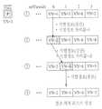
먼저 시간적 레벨 정보란, 비디오 신호로부터 시간적 확장성을 제공하기 위한 계층적인 구조에 대한 정보를 말한다(①). 이러한 시간적 레벨 정보를 통해 사용자에게 다양한 시간대의 영상을 제공할 수 있게 된다.First, temporal level information refers to information on a hierarchical structure for providing temporal scalability from a video signal (1). Through such temporal level information, it is possible to provide a user with images of various time zones.
시점 레벨 정보란, 비디오 신호로부터 시점 확장성을 제공하기 위한 계층적인 구조에 대한 정보를 말한다(②). 다시점 비디오 영상에서는 사용자에게 다양한 시간 및 시점의 영상을 제공하도록 하기 위해 시간 및 시점에 대한 레벨을 정의해 줄 필요가 있다. 이처럼 레벨 정보를 정의할 경우, 시간 및 시점에 대한 확장성(scalability)을 이용할 수 있게 된다. 따라서, 사용자는 원하는 시간 및 시점의 영상만을 볼 수도 있고, 다른 제한 조건에 따른 영상만을 볼 수 있게 된다. 상기 레벨 정보는 그 기준 조건에 따라 다양한 방법으로 다르게 설정될 수 있다. 예를 들어, 카메라의 위치에 따라 다르게 설정될 수 있고, 카메라의 배열 형태에 따라 다르게 설정될 수 있다. 또한, 상기 레벨 정보는 시점간 참조 정보를 고려하여 결정될 수도 있는데, 예를 들어, 인터 뷰 픽쳐 그룹이 I픽쳐인 시점에는 레벨을 0으로 할당하고, 인터 뷰 픽쳐 그룹이 P픽쳐인 시점에는 레벨을 1로 할당하고, 인터 뷰 픽쳐 그룹이 B픽쳐인 시점에는 레벨을 2로 할당할 수 있다. 또한, 상기 레벨 정보는 특별한 기준에 의하지 않고 임의로 설정될 수도 있다. 상기 시점 레벨 정보에 대해서는 도 4,5에서 상세히 설명하도록 한다.The viewpoint level information refers to information on a hierarchical structure for providing viewpoint scalability from a video signal (2). In a multi-view video image, it is necessary to define the levels of time and view in order to provide a user with images of various times and views. When defining the level information in this way, scalability with respect to time and time can be used. Accordingly, the user may view only an image of a desired time and time point, and may view only an image according to another constraint. The level information may be set differently in various ways according to the reference condition. For example, it may be set differently according to the position of the camera, or may be set differently according to the arrangement of the camera. In addition, the level information may be determined in consideration of the inter-view reference information. For example, when the inter-view picture group is an I picture, the level is assigned to 0, and when the inter-view picture group is a P picture, the level is changed. When the interview picture group is a B picture, the level may be allocated to 2. In addition, the level information may be arbitrarily set regardless of a special criterion. The viewpoint level information will be described in detail with reference to FIGS. 4 and 5.
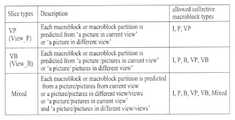
인터 뷰 픽쳐 그룹 식별 정보란, 현재 NAL 유닛의 코딩된 픽쳐가 인터 뷰 픽쳐 그룹인지 여부를 식별하는 정보를 말한다(③). 그리고, 인터 뷰 픽쳐 그룹이라 함은, 모든 슬라이스들이 동일 시간대의 프레임에 있는 슬라이스만을 참조하는 부호화된 픽쳐를 의미한다. 예를 들어, 다른 시점에 있는 슬라이스만을 참조하고 현재 시점에 있는 슬라이스는 참조하지 않는 부호화된 픽쳐를 말한다. 다시점 영상의 복호화 과정에 있어서, 시점 간의 랜덤 액세스는 가능할 수 있다. 또한, 시점간 예측을 위해서는 시점간 참조 정보가 필요한데, 상기 시점간 참조 정보를 알기 위해 인터 뷰 픽쳐 그룹 식별 정보가 이용될 수 있다. 또한, 참조 픽쳐 리스트를 생성할 때 시점간 예측을 위한 참조 픽쳐들을 추가하는데 상기 인터 뷰 픽쳐 그룹 식별 정보가 이용될 수도 있다. 그리고, 추가된 상기 시점간 예측을 위한 참조 픽쳐들을 관리하기 위해서도 이용될 수 있다. 예를 들어, 상기 참조 픽쳐들을 인터 뷰 픽쳐 그룹과 넌-인터 뷰 픽쳐 그룹으로 나누고, 시점간 예측을 수행할 때 이용되지 않는 참조 픽쳐들은 사용하지 않겠다는 마킹을 할 수 있다. 또한, 상기 인터 뷰 픽쳐 그룹 식별 정보는 가상 참조 디코더(hypothetical reference decoder)에서도 적용될 수 있다. 상기 인터 뷰 픽쳐 그룹 식별 정보에 대해서는 도 6에서 상세히 설명하도록 한다.The interview picture group identification information refers to information for identifying whether a coded picture of a current NAL unit is an interview picture group (3). The inter-view picture group means an encoded picture in which all slices refer only to slices in frames of the same time zone. For example, an encoded picture refers to only a slice at another viewpoint and no slice at the current viewpoint. In the decoding process of a multiview image, random access between views may be possible. In addition, inter-view reference information is required for inter-view prediction, and interview picture group identification information may be used to know the inter-view reference information. In addition, the inter-view picture group identification information may be used to add reference pictures for inter-view prediction when generating a reference picture list. It may also be used to manage the added reference pictures for the inter-view prediction. For example, the reference pictures may be divided into an inter-view picture group and a non-inter-view picture group, and may be marked not to use reference pictures that are not used when performing inter-view prediction. The interview picture group identification information may also be applied to a hypothetical reference decoder. The interview picture group identification information will be described in detail with reference to FIG. 6.
또한 시점 식별 정보란, 현재 시점에 있는 픽쳐와 다른 시점에 있는 픽쳐를 구별하기 위한 정보를 말한다(④). 비디오 영상 신호가 코딩될 때, 각각의 픽쳐를 식별하기 위하여 POC(Picture Order Count)와 frame_num 이 이용된다. 다시점 비디오 영상인 경우에는 시점간 예측이 수행되기 때문에 현재 시점에 있는 픽쳐와 다른 시점에 있는 픽쳐를 구별하기 위한 식별 정보가 필요하다. 따라서, 픽쳐의 시점을 식별하는 시점 식별 정보를 정의할 필요가 있다. 상기 시점 식별 정보는 비디오 신 호의 헤더 영역으로부터 획득될 수 있다. 예를 들어, 상기 헤더 영역은 NAL 헤더 영역 또는 NAL 헤더의 확장 영역일 수도 있고, 슬라이스 헤더 영역일 수도 있다. 상기 시점 식별 정보를 이용하여 현재 픽쳐와 다른 시점에 있는 픽쳐의 정보를 획득하고, 상기 다른 시점에 있는 픽쳐의 정보를 이용하여 상기 비디오 신호를 디코딩할 수 있다. 이러한 상기 시점 식별 정보는 비디오 신호의 인코딩/디코딩 과정 전반에 걸쳐 적용될 수 있다. 또한, 특정한 시점 식별자가 아닌, 시점이 고려된 frame_num을 이용하여 다시점 비디오 코딩에 그대로 적용할 수도 있다.The viewpoint identification information refers to information for distinguishing a picture at a current viewpoint from a picture at a different viewpoint (4). When a video image signal is coded, a picture order count (POC) and frame_num are used to identify each picture. In the case of a multiview video image, since inter-view prediction is performed, identification information for distinguishing a picture at a current view from a picture at a different view is required. Therefore, it is necessary to define viewpoint identification information for identifying the viewpoint of the picture. The view identification information may be obtained from a header area of a video signal. For example, the header area may be an NAL header area or an extension area of the NAL header, or may be a slice header area. The view identification information may be used to obtain information of a picture that is different from the current picture, and the video signal may be decoded using the information of the picture at the other view. The viewpoint identification information may be applied throughout the encoding / decoding process of the video signal. In addition, the frame_num may be applied to a multi-view video coding as it is, using a frame_num in consideration of a view rather than a specific view identifier.
파싱된 비트스트림은 엔트로피 디코딩부(200)를 통하여 엔트로피 디코딩되고, 각 매크로브록의 계수, 움직임 벡터 등이 추출된다. 역양자화/역변환부(300)에서는 수신된 양자화된 값에 일정한 상수를 곱하여 변환된 계수값을 획득하고, 상기 계수값을 역변환하여 화소값을 복원하게 된다. 상기 복원된 화소값을 이용하여 인트라 예측부(400)에서는 현재 픽쳐 내의 디코딩된 샘플로부터 화면내 예측을 수행하게 된다. 한편, 디블록킹 필터부(500)에서는 블록 왜곡 현상을 감소시키기 위해 각각의 코딩된 매크로블록에 적용된다. 필터는 블록의 가장자리를 부드럽게 하여 디코딩된 프레임의 화질을 향상시킨다. 필터링 과정의 선택은 경계 세기(boundary strenth)와 경계 주위의 이미지 샘플의 변화(gradient)에 의해 좌우된다. 필터링을 거친 픽쳐들은 출력되거나 참조 픽쳐로 이용하기 위해 복호 픽쳐 버퍼부(600)에 저장된다.The parsed bitstream is entropy decoded by the
복호 픽쳐 버퍼부(Decoded Picture Buffer unit)(600)에서는 화면간 예측을 수행하기 위해서 이전에 코딩된 픽쳐들을 저장하거나 개방하는 역할 등을 수행한 다. 이 때 복호 픽쳐 버퍼부(600)에 저장하거나 개방하기 위해서 각 픽쳐의 frame_num 과 POC(Picture Order Count)를 이용하게 된다. 따라서, MVC에 있어서 상기 이전에 코딩된 픽쳐들 중에는 현재 픽쳐와 다른 시점에 있는 픽쳐들도 있으므로, 이러한 픽쳐들을 참조 픽쳐로서 활용하기 위해서는 상기 frame_num 과 POC 뿐만 아니라 픽쳐의 시점을 식별하는 시점 정보도 함께 이용할 수 있다. 상기 복호 픽쳐 버퍼부(600)는 참조 픽쳐 저장부(610)와 참조 픽쳐 리스트 생성부(620)와 참조 픽쳐 관리부(640)를 포함한다. 참조 픽쳐 저장부(610)는 현재 픽쳐의 코딩을 위해 참조가 되는 픽쳐들을 저장한다. 참조 픽쳐 리스트 생성부(620)는 화면간 예측을 위한 참조 픽쳐들의 리스트를 생성하게 된다. 다시점 비디오 코딩에 있어서는 시점간 예측이 이루어질 수 있으므로 현재 픽쳐가 다른 시점에 있는 픽쳐를 참조하게 되는 경우, 시점간 예측을 위한 참조 픽쳐 리스트를 생성할 필요가 있을 수 있다. 이 때, 참조 픽쳐 리스트 생성부(620)는 시점간 예측을 위한 참조 픽쳐 리스트를 생성하기 위하여 시점에 대한 정보를 이용할 수 있다. 이는 도 3에서 상세히 설명하도록 한다.The decoded
도 3은 본 발명이 적용되는 실시예로서, 참조 픽쳐 리스트 생성부(620)의 내부 블록도를 나타낸다. 상기 참조 픽쳐 리스트 생성부(620)는 변수 유도부(625), 참조 픽쳐 리스트 초기화부(630) 및 참조 픽쳐 리스트 재배열부(640)을 포함한다.3 is an embodiment to which the present invention is applied and shows an internal block diagram of the reference
변수 유도부(625)는 참조 픽쳐 리스트 초기화에 사용되는 변수들을 유도한다. 예를 들어, 픽쳐의 식별 번호를 나타내는 frame_num 을 이용하여 상기 변수를 유도할 수 있다. 구체적 예로, 각각의 단기 참조 픽쳐에는 변수 FrameNum과 변수 FrameNumWrap 이 이용될 수 있다. 먼저 상기 변수 FrameNum은 신택스 요소인 frame_num 값과 같다. 그리고, 상기 변수 FrameNumWrap은 상기 복호 픽쳐 버퍼부(600)에서 참조 픽쳐마다 작은 번호를 할당해주기 위하여 이용될 수 있으며, 상기 변수 FrameNum으로부터 유도될 수 있다. 이렇게 유도된 상기 변수 FrameNumWrap 을 이용하여 변수 PicNum 을 유도할 수 있다. 여기서 변수 PicNum은 상기 복호 픽쳐 버퍼부(600)에서 사용되는 픽쳐의 식별 번호를 의미할 수 있다. 장기 참조 픽쳐를 나타내는 경우에는 변수 LongTermPicNum이 이용될 수 있다.The
또한, 시점간 예측을 위한 참조 픽쳐 리스트를 생성하기 위해서는 시점에 대한 정보를 이용하여 시점간 예측을 위한 참조 픽쳐 리스트를 생성하기 위한 제 1 변수(예를 들어, ViewNum)를 유도할 수 있다. 예를 들어, 픽쳐의 시점을 식별해주는 view_id 를 이용하여 상기 제 2 변수(예를 들어, ViewId)를 유도할 수 있다. 먼저 상기 제 2 변수는 신택스 요소인 상기 view_id 값과 같을 수 있다. 그리고, 제 3 변수(예를 들어, ViewIdWrap)는 상기 복호 픽쳐 버퍼부(600)에서 참조 픽쳐마다 작은 시점 식별 번호를 할당해주기 위하여 이용될 수 있으며, 상기 제 2 변수로부터 유도될 수 있다. 여기서 상기 제 1 변수(ViewNum)는 상기 복호 픽쳐 버퍼부(600)에서 사용되는 픽쳐의 시점 식별 번호를 의미할 수 있다. 다만, 다시점 비디오 코딩에서는 시간적 예측에 이용되는 참조 픽쳐의 수에 비해 시점간 예측에 이용되는 참조 픽쳐의 수가 상대적으로 작을 수 있으므로, 장기 참조 픽쳐의 시점 식별 번호를 표시하기 위한 별도의 변수를 정의하지 않을 수 있다.In addition, in order to generate a reference picture list for inter-view prediction, a first variable (eg, ViewNum) for generating a reference picture list for inter-view prediction may be derived using information about the viewpoint. For example, the second variable (eg, ViewId) may be derived by using view_id identifying a viewpoint of the picture. First, the second variable may be equal to the view_id value that is a syntax element. The third variable (eg, ViewIdWrap) may be used by the decoded
참조 픽쳐 리스트 초기화부(630)는 상기 변수들을 이용하여 참조 픽쳐 리스 트를 초기화한다. 이때 참조 픽쳐 리스트의 초기화 과정은 슬라이스 타입에 따라 그 방식이 달라질 수 있다. 예를 들어, P슬라이스를 디코딩할 경우에는 디코딩 순서에 기초하여 참조 픽쳐 번호를 할당할 수 있으며, B슬라이스를 디코딩할 경우에는 픽쳐 출력 순서에 기초하여 참조 픽쳐 번호를 할당할 수 있다. 또한, 시점간 예측을 위한 참조 픽쳐 리스트를 초기화할 경우에는 상기 제 1 변수, 즉 시점 정보로부터 유도된 변수에 기초하여 참조 픽쳐에 번호를 할당할 수 있다.The reference picture
참조 픽쳐 리스트 재배열부(640)는 초기화된 참조 픽쳐 리스트에서 빈번하게 참조된 픽쳐에 더 작은 번호를 할당함으로써 압축률을 향상시키는 역할을 수행한다. 참조 픽쳐를 지정하는 참조 픽쳐 번호는 블록단위로 부호화되는데 참조 픽쳐 번호의 부호화를 위한 참조 픽쳐 번호가 작을수록 작은 비트수의 부호가 할당되기 때문이다.The reference
또한, 상기 참조 픽쳐 리스트 재배열부(640)는 슬라이스 타입 확인부(642), 참조 픽쳐 리스트0 재배열부(643) 및 참조 픽쳐 리스트1 재배열부(645)를 포함한다. 슬라이스 타입 확인부(642)는 초기화된 참조 픽쳐 리스트가 입력될 경우, 디코딩하려는 슬라이스의 타입을 확인하여 참조 픽쳐 리스트0을 재배열할지, 참조 픽쳐 리스트1을 재배열할지를 결정하게 된다. 이에 따라 참조 픽쳐 리스트0/1 재배열부(643,645)에서는, 예를 들어, 슬라이스 타입이 I슬라이스가 아닌 경우에는 참조 픽쳐 리스트0의 재배열을 수행하고, 슬라이스 타입이 B슬라이스인 경우에는 참조 픽쳐 리스트1의 재배열도 수행한다. 이렇게 재배열 과정이 종료되면, 참조 픽쳐 리스트가 생성된다.In addition, the reference picture
그리고, 상기 참조 픽쳐 리스트0/1 재배열부(643,645)는 각각 식별정보 획득부(643A,645A)와 참조번호 할당 변경부(643B,645B)를 포함한다. 식별정보 획득부(643A,645A)는 참조 픽쳐 리스트의 재배열을 수행할지 여부를 나타내는 플래그 정보에 따라 참조 픽쳐 리스트의 재배열을 수행하게 되는 경우, 참조 번호의 할당 방법을 나타내는 식별 정보(reordering_of_pic_nums_idc)를 입력받는다. 참조번호 할당 변경부(643B,645B)에서는 상기 식별 정보에 따라 참조번호의 할당을 변경함으로써 참조 픽쳐 리스트를 재배열하게 된다.The
또한, 상기 참조 픽쳐 리스트 재배열부(640)는 다른 방식을 적용하여 수행될 수도 있다. 예를 들어, 슬라이스 타입 확인부(642)를 거치기 전에 전송된 NAL의 타입을 확인하여 MVC NAL 인 경우와 그렇지 않은 경우로 나누어서 재배열을 할 수도 있다.In addition, the reference
참조 픽쳐 관리부(640)는 보다 유연하게 화면간 예측을 실현하기 위하여 참조 픽쳐를 관리한다. 예를 들어, 적응 메모리 관리 방법(Memory Management Control Operation Method)과 이동 윈도우 방법(Sliding Window Method)이 이용될 수 있다. 이는 참조 픽쳐와 비참조 픽쳐의 메모리를 하나의 메모리로 통일하여 관리하고 적은 메모리로 효율적으로 관리하기 위함이다. 다시점 비디오 코딩에 있어서, 시점 방향의 픽쳐들은 픽쳐 출력 순서(Picture Order Count)가 동일하기 때문에 이들의 마킹을 위해서는 각 픽쳐의 시점을 식별해주는 정보가 이용될 수 있다. 이러한 과정을 통해 관리되는 참조 픽쳐들은 인터 예측부(700)에서 이용될 수 있다.The
인터 예측부(700)에서는 복호 픽쳐 버퍼부(600)에 저장된 참조 픽쳐를 이용하여 화면간 예측을 수행한다. 인터 코딩된 매크로블록은 매크로블록 파티션으로 나누어질 수 있으며, 각 매크로블록 파티션은 하나 또는 두개의 참조 픽쳐로부터 예측될 수 있다. 상기 인터 예측부(700)는 움직임 보상부(710)와 휘도 보상부(720), 휘도 차분 예측부(730), 시점 합성 예측부(740) 및 가중치 예측부(750) 등을 포함한다.The
움직임 보상부(710)에서는 엔트로피 디코딩부(200)로부터 전송된 정보들을 이용하여 현재 블록의 움직임을 보상한다. 비디오 신호로부터 현재 블록에 이웃하는 블록들의 움직임 벡터를 추출하고, 상기 현재 블록의 움직임 벡터 휘도 차분를 획득한다. 상기 획득된 움직임 벡터 휘도 차분와 비디오 신호로부터 추출되는 차분 벡터를 이용하여 현재 블록의 움직임을 보상한다. 또한, 이러한 움직임 보상은 하나의 참조 픽쳐를 이용하여 수행될 수도 있고, 복수의 픽쳐를 이용하여 수행될 수도 있다. 다시점 비디오 코딩에 있어서, 현재 픽쳐가 다른 시점에 있는 픽쳐들을 참조하게 되는 경우, 상기 복호 픽쳐 버퍼부(600)에 저장되어 있는 시점간 예측을 위한 참조 픽쳐 리스트에 대한 정보를 이용하여 움직임 보상을 수행할 수 있다. 또한, 그 픽쳐의 시점을 식별하는 시점 정보를 이용하여 움직임 보상을 수행할 수도 있다. 또한, 직접 예측 모드(direct mode)는 부호화가 끝난 블록의 움직임 정보로부터 현재 블록의 움직임 정보를 예측하는 부호화 모드이다. 이러한 방법은 움직임 정보를 부호화할 때 필요한 비트수가 절약되기 때문에 압축 효율이 향상된다. 예를 들어, 시간 직접 예측 모드(temporal direct mode)는 시간 방향의 움직임 정보 상 관도를 이용하여 현재 블록의 움직임 정보를 예측하게 된다. 이 방법과 유사하게 본 발명에서는 시점 방향의 움직임 정보 상관도를 이용하여 현재 블록의 움직임 정보를 예측할 수 있다.The
또한, 입력된 비트스트림이 다시점 영상에 해당되는 경우, 각 시점 영상(view sequence)들은 각기 다른 카메라에서 취득된 영상들이기 때문에 카메라의 내외적 요인으로 인하여 휘도 (illumination) 차이가 발생하게 된다. 이를 방지하기 위해서 휘도 보상부(720)에서는 휘도 보상(illumination compensation)을 수행하게 된다. 휘도 보상을 수행함에 있어서, 비디오 신호의 일정 계층에 대한 휘도 보상 수행여부를 나타내는 플래그 정보를 이용할 수 있다. 예를 들어, 해당 슬라이스 또는 해당 매크로블록의 휘도 보상 수행여부를 나타내는 플래그 정보를 이용하여 휘도 보상을 수행할 수 있다. 또한, 상기 플래그 정보를 이용하여 휘도 보상을 수행함에 있어서, 여러 가지 매크로블록의 타입(예를 들어, 인터16×16모드 또는 B-skip모드 또는 직접 예측 모드 등)에 적용될 수 있다.In addition, when the input bitstream corresponds to a multi-view image, since the view sequences are images obtained from different cameras, luminance differences occur due to internal and external factors of the camera. In order to prevent this, the
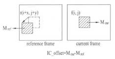
또한, 휘도 보상을 수행함에 있어서, 현재 블록을 복원하기 위하여 주변 블록의 정보 또는 현재 블록과 다른 시점에 있는 블록의 정보를 이용할 수 있으며, 현재 블록의 휘도 차분값을 이용할 수도 있다. 이 때 현재 블록이 다른 시점에 있는 블록들을 참조하게 되는 경우, 상기 복호 픽쳐 버퍼부(600)에 저장되어 있는 시점간 예측을 위한 참조 픽쳐 리스트에 대한 정보를 이용하여 휘도 보상을 수행할 수 있다. 여기서 현재 블록의 휘도 차분 값이란, 현재 블록의 평균 화소값과 그에 대응하는 참조 블록의 평균 화소값 사이의 차이를 말한다. 상기 휘도 차분 값을 이 용하는 일례로, 상기 현재 블록의 이웃 블록들을 이용하여 상기 현재 블록의 휘도 차분 예측값을 획득하고, 상기 휘도 차분 값과 상기 휘도 차분 예측값와의 차이값인 휘도 차분 레지듀얼(IC offset residual)을 이용할 수 있다. 따라서, 디코딩부에서는 상기 휘도 차분 레지듀얼과 상기 휘도 차분 예측값을 이용하여 상기 현재 블록의 휘도 차분 값을 복원할 수 있다. 또한, 현재 블록의 휘도 차분 예측값을 획득함에 있어서, 이웃 블록의 정보를 이용할 수 있다. 예를 들어, 이웃 블록의 휘도 차분 값을 이용하여 현재 블록의 휘도 차분 값을 예측할 수 있는데, 이에 앞서 상기 현재 블록의 참조 번호(reference index)와 상기 이웃 블록의 참조 번호가 동일한지 여부를 확인하고, 그 확인 결과에 따라 어떤 이웃 블록을 이용할지, 또는 어떤 값을 이용할지가 결정될 수 있다.In addition, in performing the luminance compensation, information of a neighboring block or information on a block that is different from the current block may be used to restore the current block, and a luminance difference value of the current block may be used. In this case, when the current block refers to blocks at different views, luminance compensation may be performed using information on a reference picture list for inter-view prediction stored in the decoded
시점 합성 예측부(740)는 현재 픽쳐의 시점에 이웃하는 시점에 있는 픽쳐들을 이용하여 새로운 시점의 픽쳐들을 합성하고, 합성된 새로운 시점의 픽쳐들을 이용하여 현재 픽쳐를 예측하기 위해 이용된다. 디코딩부에서는 인코딩부로부터 전송된 시점간 합성 예측 식별자에 따라서 새로운 시점의 픽쳐를 합성할지 여부를 판단할 수 있다. 예를 들어, view_synthesize_pred_flag = 1 이거나, 또는 view_syn_pred_flag = 1 인 경우, 각각 새로운 시점의 슬라이스 또는 매크로블록을 합성하게 된다. 이 때, 상기 시점간 합성 예측 식별자가 새로운 시점을 생성할 것임을 알려주었을 때, 픽쳐의 시점을 식별하는 시점 정보를 이용하여 새로운 시점의 픽쳐를 생성할 수 있다. 또한, 상기 새로운 시점의 픽쳐를 합성하고 현재 픽쳐를 예측할 때, 상기 새로운 시점의 픽쳐를 참조 픽쳐로 이용하기 위해 상기 시점 정보 가 이용될 수 있다.The view
가중치 예측부(750)는 밝기가 시간적으로 변화하는 영상을 부호화할 때 영상의 화질이 크게 열화되는 현상을 보상하기 위해 이용된다. MVC에서는 시간적으로 밝기가 변화하는 영상뿐만 아니라 다른 시점에 있는 영상과의 밝기 차이를 보상하기 위해 가중치 예측이 수행될 수 있다. 예를 들어, 가중치 예측 방법에는 명시적(explicit) 가중치 예측 방법과 암시적(implicit) 가중치 예측 방법이 있다. 상기 명시적 가중치 예측 방법에는 한 장의 참조 픽쳐를 이용하는 경우 또는 두 장의 참조 픽쳐를 이용하는 경우가 있다. 한 장의 참조 픽쳐를 이용하는 경우에는 움직임 보상에 해당하는 예측 신호에 가중치 계수를 곱해서 예측 신호를 생성하고, 두 장의 참조 픽쳐를 이용하는 경우에는 움직임 보상에 해당하는 예측 신호에 가중치 계수를 곱한 값에 오프셋 값을 더하여 예측 신호를 생성한다. 암시적 가중치 예측 방법은 참조 픽쳐로부터의 거리를 이용하여 가중치 예측을 수행한다. 상기 참조 픽쳐로부터의 거리를 구하는 방법으로는, 예를 들어, 픽쳐의 출력 순서를 나타내는 값인 POC(Picture Order Count)를 이용하는 경우가 있는데, 상기 POC는 각 픽쳐의 시점을 구분할 수 있도록 고려하여 만들어진 POC이다. 또는, 다른 시점에 있는 픽쳐에 대하여 가중치 계수를 획득할 때, 각 픽쳐의 시점 사이의 거리를 계산하기 위하여 픽쳐의 시점을 식별하는 시점 정보가 이용될 수 있다.The
또한, 비디오 신호 코딩에 있어서, 특정 어플리케이션을 위해서 또는 다른 목적을 위해서 깊이 정보를 이용할 수 있다. 깊이 정보란, 시점 간의 변이 차이를 나타낼 수 있는 정보를 의미할 수 있다. 예를 들어, 시점 간의 예측을 통해서 변이 벡터를 획득할 수 있는데 상기 획득된 변이 벡터는 현재 블록의 변이 보상을 위해 디코딩 장치에 전송되어야 한다. 하지만, 깊이 맵을 구하여 이를 디코딩 장치에 전송하게 될 경우, 상기 변이 벡터를 디코딩 장치에 전송할 필요없이 상기 깊이 맵(depth map)(또는 변이 맵(disparity map))으로부터 상기 변이 벡터를 유추해낼 수 있다. 이러한 경우, 디코딩 장치에 전송되어져야 할 깊이 정보의 비트수를 감소시킬 수 있는 장점이 있다. 따라서, 상기 깊이 맵으로부터 변이 벡터를 유추함으로써 새로운 변이 보상하는 방법이 제공될 수 있다. 위와 같이 상기 깊이 맵으로부터 변이 벡터를 유추하는 과정에서 다른 시점의 픽쳐를 이용할 경우, 픽쳐의 시점을 식별할 수 있는 시점 정보가 이용될 수 있다.In addition, in video signal coding, depth information may be used for specific applications or for other purposes. Depth information may refer to information that may indicate a difference in variation between viewpoints. For example, a disparity vector may be obtained through inter-view prediction, and the obtained disparity vector should be transmitted to the decoding apparatus to compensate for disparity of the current block. However, when the depth map is obtained and transmitted to the decoding apparatus, the disparity vector may be inferred from the depth map (or disparity map) without transmitting the disparity vector to the decoding apparatus. . In this case, there is an advantage in that the number of bits of depth information to be transmitted to the decoding apparatus can be reduced. Accordingly, a method of compensating for the new variation may be provided by inferring the disparity vector from the depth map. As described above, when a picture of another viewpoint is used in the process of inferring the disparity vector from the depth map, viewpoint information for identifying the viewpoint of the picture may be used.
상기와 같은 과정을 통해 인터 예측된 픽쳐들과 인트라 예측된 픽쳐들은 예측 모드에 따라 선택되어 현재 픽쳐를 복원하게 된다. 이하에서는 비디오 신호의 효율적인 디코딩 방법을 제공하기 위한 다양한 실시예들을 설명하도록 한다.Through the above process, the inter predicted pictures and the intra predicted pictures are selected according to the prediction mode to reconstruct the current picture. Hereinafter, various embodiments for providing an efficient decoding method of a video signal will be described.
도4는 본 발명이 적용된 실시예로서, 비디오 신호의 시점 확장성(view scalability)을 제공하기 위한 레벨 정보의 계층적 구조를 나타낸다.FIG. 4 is an embodiment to which the present invention is applied and shows a hierarchical structure of level information for providing view scalability of a video signal.
각 시점의 레벨 정보는 시점간 참조 정보를 고려하여 결정될 수 있다. 예를 들어, I픽쳐 없이는 P픽쳐와 B픽쳐의 디코딩이 불가능하기 때문에 인터 뷰 픽쳐 그룹이 I픽쳐인 기준 시점(Base view)에는 level=0을 할당할 수 있고, 앵커 쳐가 P픽쳐인 시점에는 level=1을 할당할 수 있으며, 인터 뷰 픽쳐 그룹이 B픽쳐인 시점에는 level=2를 할당할 수 있다. 하지만 특정 기준에 따라 임의대로 레벨 정보를 결정할 수도 있다.Level information of each viewpoint may be determined in consideration of inter-view reference information. For example, since I and P pictures cannot be decoded without an I picture, level = 0 can be assigned to the base view where the inter-view picture group is an I picture, and when the anchor picture is a P picture, level = 1 may be allocated, and level = 2 may be allocated when the interview picture group is a B picture. However, level information may be arbitrarily determined according to specific criteria.
또한, 레벨 정보는 특정 기준에 따라 임의대로 결정될 수 있고, 또는 기준없이 랜덤하게 결정될 수도 있다. 예를 들어, 시점을 기준으로 레벨 정보를 결정하게 되는 경우, V0 시점을 기준 시점(base view)으로 설정하여 view level 0, 하나의 시점에 있는 픽쳐들을 이용하여 예측된 픽쳐들의 시점을 view level 1, 그리고 복수개의 시점에 있는 픽쳐들을 이용하여 예측된 픽쳐들의 시점을 view level 2로 설정할 수 있다. 이 경우, 기존의 디코더(예를 들어, H.264/AVC, MPEG-2, MPEG-4 등)와 호환성을 가지기 위한 적어도 하나의 시점 영상(view sequence)이 필요할 수 있다. 이러한 기준 시점은 다시점(multi view) 중 부호화의 기준이 되며, 이는 다른 시점의 예측을 위한 참조 시점(reference view)에 해당될 수 있다. MVC(Multiview Video Coding)에서 기준 시점에 해당되는 영상은 종래 일반적인 영상 부호화 방식(MPEG-2, MPEG-4, H.263, H.264 등)에 의해 부호화되어 독립적인 비트스트림으로 형성될 수 있다. 기준 시점에 해당되는 영상은 H.264/AVC와 호환될 수도 있고, 되지 않을 수도 있다. 하지만, H.264/AVC와 호환될 수 있는 시점의 영상은 기준 시점이 된다.In addition, the level information may be arbitrarily determined according to a specific criterion, or may be randomly determined without the criterion. For example, when the level information is determined based on the view point, the
상기 도 4에서 알 수 있듯이, 상기 V0 시점에 있는 픽쳐들을 이용하여 예측된 픽쳐들의 시점인 V2 시점, V2 시점에 있는 픽쳐들을 이용하여 예측된 픽쳐들의 시점인 V4 시점과 V4 시점에 있는 픽쳐들을 이용하여 예측된 픽쳐들의 시점인 V6 시점, 그리고 V6 시점에 있는 픽쳐들을 이용하여 예측된 픽쳐들의 시점인 V7 시점을 view level 1 으로 설정할 수 있다. 그리고, V0 시점과 V2 시점에 있는 픽쳐들을 이용하여 예측된 픽쳐들의 시점인 V1 시점, 그리고 동일한 방식으로 예측된 V3 시점, V5 시점은 view level 2 로 설정할 수 있다. 따라서, 사용자의 디코더가 다시점 비디오 영상을 볼 수 없는 경우에는 상기 view level 0 에 해당되는 시점의 영상들만을 디코딩하게 된다. 또는 사용자의 디코더가 프로파일 정보에 의해 제한되는 경우에도 제한된 view level의 정보만을 디코딩할 수 있게 된다. 여기서, 프로파일(profile)이란 비디오 부호화/복호화 과정에서 알고리즘상 들어가는 기술적 구성요소를 규격화한 것을 의미한다. 즉, 압축된 영상의 비트열을 복호하기 위해 필요한 기술요소의 집합으로서 일종의 서브 규격이라 할 수 있다.As can be seen in FIG. 4, pictures at a view point V4 and a view point V4 which are views of pictures predicted using pictures at a view point V2 and a view point V2 that are predicted using pictures at the view point V0 are used. A
본 발명이 적용되는 다른 일실시예로서, 레벨 정보는 카메라의 위치에 따라 달라질 수 있다. 예를 들어, V0 시점과 V1 시점은 정면에 위치한 카메라에 의해 획득된 영상들이고, V2 시점과 V3 시점은 후면에 위치한 카메라에 의해 획득된 영상들이고, V4 시점과 V5 시점은 좌측에 위치한 카메라에 의해 획득된 영상들이며, V6 시점과 V7 시점은 우측에 위치한 카메라에 의해 획득된 영상들이라고 가정할 경우, V0 시점과 V1 시점을 view level 0로, V2 시점과 V3 시점은 view level 1로, V4 시점과 V5 시점은 view level 2로, V6 시점과 V7 시점은 view level 3로 설정할 수도 있다. 또 다른 실시예로서, 레벨 정보는 카메라의 배열 형태에 따라 달라질 수 있다. 또한, 레벨 정보는 특별한 기준에 의하지 않고 임의로 결정될 수도 있다.In another embodiment to which the present invention is applied, the level information may vary depending on the position of the camera. For example, viewpoints V0 and V1 are images acquired by a camera located in the front, views V2 and V3 are images acquired by a camera located at the rear, and views V4 and V5 are viewed by a camera located on the left. When the V6 and V7 views are acquired by the camera located on the right side, the V0 and V1 views are
도 5는 본 발명이 적용되는 일실시예로서, NAL헤더의 확장 영역 내에 레벨 정보를 포함하는 NAL단위의 구성을 나타낸다.FIG. 5 illustrates a configuration of an NAL unit including level information in an extended area of a NAL header according to an embodiment to which the present invention is applied.
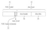
NAL 단위는 기본적으로 NAL헤더와 RBSP의 두 부분으로 구성된다. NAL헤더에는 그 NAL 단위의 참조픽처가 되는 슬라이스가 포함되어 있는지 여부를 나타내는 플래그 정보(nal_ref_idc)와 NAL 단위의 종류를 나타내는 식별자(nal_unit_type)가 포함되어 있다. 그리고, 시점 확장성(view scalability)을 제공하기 위한 계층적인 구조에 대한 정보를 나타내는 레벨 정보(view_level)도 포함할 수 있다.The NAL unit basically consists of two parts: the NAL header and the RBSP. The NAL header includes flag information (nal_ref_idc) indicating whether a slice serving as a reference picture of the NAL unit is included and an identifier (nal_unit_type) indicating the type of the NAL unit. And, it may also include level information (view_level) indicating information on a hierarchical structure for providing view scalability.
RBSP 에는 압축된 원본의 데이터를 저장하며, RBSP 의 길이를 8비트의 배수로 표현하기 위해 RBSP 의 마지막에 RBSP trailing bit(RBSP 채워넣기 비트)를 첨가한다. 이러한 NAL 단위의 종류에는 IDR (Instantaneous Decoding Refresh, 순간 복호 리프레쉬) 픽쳐, SPS (Sequence Parameter Set, 시퀀스 파라미터 세트), PPS (Picture Parameter Set, 픽쳐 파라미터 세트), SEI (Supplemental Enhancement Information, 보충적 부가정보) 등이 있다.The RBSP stores the compressed original data and adds an RBSP trailing bit to the end of the RBSP to express the length of the RBSP in multiples of 8 bits. These NAL unit types include Instantaneous Decoding Refresh (IDR) pictures, Sequence Parameter Set (SPS), Picture Parameter Set (PPS), and Supplemental Enhancement Information (SEI). Etc.
상기 NAL 헤더에는 시점 식별자(view identifer)에 대한 정보를 포함하고 있으며, 시점 레벨에 따라서 디코딩을 수행하는 과정에서 시점 식별자를 참조하여 해당 시점 레벨의 비디오 영상을 디코딩한다. 상기 NAL 단위는 NAL 헤더(header)(51)와 슬라이스 계층(slice layer)(53)을 포함하며, 상기 NAL 헤더(710)는 NAL 헤더 확장 영역(NAL header extention) (52)을 포함하고, 상기 슬라이스 계층(53)은 슬라이스 헤더(slice header)(54)와 슬라이스 데이터(slice data)(55)를 포함한다. 상기 NAL 헤더(51)는 NAL 단위의 종류를 나타내는 식별자(nal_unit_type)를 포함하고 있는데, 예를 들어, 상기 NAL 단위의 종류를 나타내는 식별자는 스케일러블 비디오 코딩(Scalable Video Coding)과 다시점 비디오 코딩(Multi-view Video Coding) 모두를 위한 식별자일 수 있다. 이 때 상기 NAL 헤더 확장 영역(52)에서는 현재 NAL이 스케일러블 비디오 코딩을 위한 NAL인지 다시점 비디오 코딩을 위한 NAL인지를 구별하는 플래그 정보를 포함할 수 있고, 상기 플래그 정보에 따라 상기 현재 NAL의 확장 정보를 포함할 수 있다. 예를 들어, 상기 플래그 정보에 따라 상기 현재 NAL이 다시점 비디오 코딩을 위한 NAL인 경우, 상기 NAL 헤더 확장 영역(52)은 시점 확장성(view scalability)을 제공하기 위한 계층적인 구조에 대한 정보를 나타내는 레벨 정보(view_level)를 포함할 수 있다.The NAL header includes information about a view identifier, and decodes a video image of a corresponding view level with reference to the view identifier in the process of decoding according to the view level. The NAL unit includes a
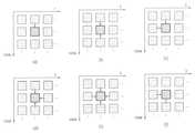
도6은 본 발명이 적용되는 실시예로서, 인터 뷰 픽쳐 그룹의 개념을 설명하기 위한 다시점 영상 신호의 전체적인 예측 구조를 나타낸다.6 is an embodiment to which the present invention is applied and shows an overall prediction structure of a multiview image signal for explaining the concept of an interview picture group.
도 6에 나타난 바와 같이 가로축의 T0 ∼ T100 은 각각 시간에 따른 프레임을 나타낸 것이고, 세로축의 S0 ∼ S7은 각각 시점에 따른 프레임을 나타낸 것이다. 예를 들어, T0에 있는 픽쳐들은 같은 시간대(T0)에 서로 다른 카메라에서 찍은 영상들을 의미하며, S0 에 있는 픽쳐들은 한 대의 카메라에서 찍은 다른 시간대의 영상들을 의미한다. 또한, 도면 상의 화살표들은 각 픽쳐들의 예측 방향과 순서를 나타낸 것으로서, 예를 들어, T0 시간대의 S2 시점에 있는 P0 픽쳐는 I0로부터 예측된 픽쳐이며, 이는 TO 시간대의 S4 시점에 있는 P0 픽쳐의 참조 픽쳐가 된다. 또한, S2 시점의 T4, T2 시간대에 있는 B1, B2 픽쳐의 참조 픽쳐가 된다.As shown in FIG. 6, T0 to T100 on the horizontal axis represent frames over time, and S0 to S7 on the vertical axis represent frames according to viewpoints, respectively. For example, pictures in T0 refer to images taken by different cameras in the same time zone (T0), and pictures in S0 refer to images in different time zones taken by one camera. In addition, the arrows in the drawings indicate the prediction direction and the order of each picture. For example, a P0 picture at S2 time point in the T0 time zone is a picture predicted from I0, which refers to a P0 picture at S4 time point in the TO time zone. It becomes a picture. It is also a reference picture of the B1 and B2 pictures in the T4 and T2 time zones at the time S2.
다시점 영상의 복호화 과정에 있어서, 시점 간의 랜덤 액세스는 필수적이다. 따라서, 복호화 노력을 최소화하면서 임의 시점에 대한 액세스가 가능하도록 하여야 한다. 여기서 효율적인 랜덤 액세스를 실현하기 위하여 인터 뷰 픽쳐 그룹의 개념이 필요할 수 있다. 인터 뷰 픽쳐 그룹이라 함은, 모든 슬라이스들이 동일 시간대의 프레임에 있는 슬라이스만을 참조하는 부호화된 픽쳐를 의미한다. 예를 들어, 다른 시점에 있는 슬라이스만을 참조하고 현재 시점에 있는 슬라이스는 참조하지 않는 부호화된 픽쳐를 말한다. 도 6에서 보면, T0 시간대의 S0 시점에 있는 I0픽쳐가 인터 뷰 픽쳐 그룹이라면, 같은 시간대에 있는, 즉 T0 시간대의 다른 시점에 있는 모든 픽쳐들 또한 인터 뷰 픽쳐 그룹이 된다. 또 다른 예로서, T8 시간대의 S0 시점에 있는 I0픽쳐가 인터 뷰 픽쳐 그룹이라면, 같은 시간대에 있는, 즉 T8 시간대의 다른 시점에 있는 모든 픽쳐들 또한 인터 뷰 픽쳐 그룹이 된다. 마찬가지로, T16, ..., T96, T100 에 있는 모든 픽쳐들이 인터 뷰 픽쳐 그룹의 예가 된다.In the decoding process of a multiview image, random access between viewpoints is essential. Therefore, access to arbitrary time points should be made possible while minimizing decryption effort. In this case, the concept of an inter-view picture group may be necessary to realize efficient random access. The interview picture group refers to an encoded picture in which all slices refer only to slices in frames of the same time zone. For example, an encoded picture refers to only a slice at another viewpoint and no slice at the current viewpoint. In FIG. 6, if the I0 picture at the time S0 at the time zone T0 is an interview picture group, all pictures in the same time zone, that is, at another time point in the time zone T0, are also interview picture groups. As another example, if an I0 picture at time S0 in the T8 time zone is an interview picture group, all pictures in the same time zone, that is, at different time points in the T8 time zone, are also interview picture groups. Likewise, all pictures in T16, ..., T96, T100 are examples of interview picture groups.
도 7은 본 발명이 적용되는 실시예로서, 새롭게 정의된 인터 뷰 픽쳐 그룹의 개념을 설명하기 위한 예측 구조를 나타낸다.7 is an embodiment to which the present invention is applied and shows a prediction structure for explaining the concept of a newly defined inter-view picture group.
MVC의 전반적인 예측 구조에 있어서, GOP는 I 픽쳐로부터 시작될 수 있으며, 상기 I 픽쳐는 H.264/AVC와 호환 가능하다. 따라서, H.264/AVC와 호환 가능한 모든 인터 뷰 픽쳐 그룹들은 항상 I 픽쳐가 될 수 있다. 그러나, 상기 I 픽쳐들을 P 픽쳐로 대체하게 될 경우, 우리는 보다 효율적인 코딩이 가능해질 수 있다. 즉, GOP가 H.264/AVC와 호환 가능한 P 픽쳐로 시작하도록 하는 예측 구조를 이용할 경우 보다 효율적인 코딩이 가능해질 것이다.In the overall prediction structure of MVC, a GOP can be started from an I picture, and the I picture is compatible with H.264 / AVC. Thus, all interview picture groups compatible with H.264 / AVC can always be I pictures. However, if we replace the I pictures with P pictures, we can enable more efficient coding. In other words, more efficient coding will be enabled if the GOP starts with a P picture that is compatible with H.264 / AVC.
이 때, 인터 뷰 픽쳐 그룹을 다시 정의하면, 모든 슬라이스들이 동일 시간대의 프레임에 있는 슬라이스뿐만 아니라 동일 시점의 다른 시간대에 있는 슬라이스도 참조할 수 있는 부호화된 픽쳐가 된다. 다만, 동일 시점의 다른 시간대에 있는 슬라이스를 참조하는 경우는 오로지 H.264/AVC와 호환 가능한 인터 뷰 픽쳐 그룹에 한할 수 있다. 예를 들어, 도 6에서 S0 시점의 T8 시간에 있는 P 픽쳐는 새롭게 정 의된 인터 뷰 픽쳐 그룹이 될 수 있으며, 마찬가지로 S0 시점의 T96 시간에 있는 P 픽쳐, 그리고 S0 시점의 T100 시간에 있는 P 픽쳐가 상기 새롭게 정의된 인터 뷰 픽쳐 그룹이 될 수 있다. 또는 상기 인터 뷰 픽쳐 그룹은 기준 시점인 경우에 한하여 정의될 수도 있다.In this case, if the interview picture group is redefined, all slices become encoded pictures that may refer not only to slices in the frame of the same time zone but also slices in different time zones of the same viewpoint. However, when referring to slices in different time zones at the same time, it may be limited to an interview picture group compatible with H.264 / AVC. For example, in FIG. 6, a P picture at time T8 at time S0 may be a newly defined interview picture group, similarly a P picture at time T96 at time S0, and P at time T100 at time S0. The picture may be the newly defined inter-view picture group. Alternatively, the inter view picture group may be defined only in the case of a reference view.
인터 뷰 픽쳐 그룹이 디코딩된 후, 차례로 코딩된 모든 픽쳐들은 출력 순서상 인터 뷰 픽쳐 그룹에 선행하여 디코딩된 픽쳐로부터 인터-프리딕션(inter-prediction)없이 디코딩된다.After the inter-view picture group is decoded, all pictures coded in turn are decoded without inter-prediction from the decoded picture prior to the inter-view picture group in output order.
따라서, 상기 도 6 및 도 7의 다시점 비디오 영상의 전반적인 코딩 구조에 따를 때, 인터 뷰 픽쳐 그룹과 넌-인터 뷰 픽쳐 그룹의 시점간 참조 정보가 다르기 때문에 상기 인터 뷰 픽쳐 그룹 식별 정보에 따라 인터 뷰 픽쳐 그룹과 넌-인터 뷰 픽쳐 그룹을 구별할 필요가 있다.Therefore, according to the overall coding structure of the multi-view video image of FIGS. 6 and 7, since the inter-view picture groups and the non-inter-view picture group reference information are different from each other, the inter-view picture group identification information may be used according to the inter-view picture group identification information. It is necessary to distinguish between view picture groups and non-inter view picture groups.
상기 시점간 참조 정보는, 시점간 영상들이 어떠한 구조로 예측되었는지를 알 수 있는 정보를 말한다. 이는 비디오 신호의 데이터 영역로부터 획득될 수 있는데, 예를 들어, 시퀀스 파라미터 셋 영역으로부터 획득될 수 있다. 또한, 상기 시점간 참조 정보는 참조 픽쳐의 개수와 참조 픽쳐의 시점 정보를 이용하여 파악할 수 있다. 예를 들어, 먼저 전체 시점의 개수를 획득하고, 상기 전체 시점의 개수에 근거하여 각 시점을 구별하는 시점 정보를 파악할 수 있다. 그리고, 각 시점마다 참조 방향에 대한 참조 픽쳐의 개수를 획득할 수 있다. 상기 참조 픽쳐의 개수에 따라 각 참조 픽쳐의 시점 정보를 획득할 수 있다. 이러한 방식을 통해서 상기 시점간 참조 정보가 획득될 수 있으며, 상기 시점간 참조 정보는 인터 뷰 픽쳐 그룹 일 경우와 넌-인터 뷰 픽쳐 그룹일 경우로 나누어서 파악될 수 있다. 이는 현재 NAL에 있는 코딩된 슬라이스가 인터 뷰 픽쳐 그룹인지 여부를 나타내는 인터 뷰 픽쳐 그룹 식별 정보를 이용하여 알 수 있다. 이하 도 8에서는 상기 인터 뷰 픽쳐 그룹 식별 정보에 대하여 상세히 알아본다.The inter-view reference information refers to information capable of knowing what structure the inter-view images are predicted. This may be obtained from the data region of the video signal, for example from the sequence parameter set region. The inter-view reference information may be determined using the number of reference pictures and the view information of the reference picture. For example, first, the number of all viewpoints may be obtained, and viewpoint information for distinguishing each viewpoint may be determined based on the number of all viewpoints. In addition, the number of reference pictures with respect to the reference direction may be obtained at each viewpoint. View information of each reference picture may be obtained according to the number of the reference pictures. In this manner, the inter-view reference information may be obtained, and the inter-view reference information may be identified by being divided into an inter-view picture group and a non-inter-view picture group. This can be known using the interview picture group identification information indicating whether the coded slice in the current NAL is an interview picture group. Hereinafter, the inter-view picture group identification information will be described in detail with reference to FIG. 8.
도 8은 본 발명이 적용되는 실시예로서, 인터 뷰 픽쳐 그룹 식별 정보를 이용하여 다시점 영상을 디코딩하는 장치의 개략적인 블록도를 나타낸다.8 is a block diagram of an apparatus for decoding a multiview image using interview picture group identification information according to an embodiment to which the present invention is applied.
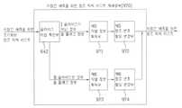
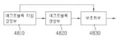
본 실시예에서의 디코딩 장치는 비트스트림 판단부(81), 인터 뷰 픽쳐 그룹 식별 정보 획득부(82) 및 다시점 영상 디코딩부(83)를 포함한다. 비트스트림 판단부(81)에서는 비트스트림이 입력되면 상기 비트스트림이 스케일러블 비디오 코딩된 비트스트림인지, 아니면 다시점 비디오 코딩된 비트스트림인지 여부를 판단하게 된다. 이는 비트스트림으로 날라오는 플래그 정보에 의해 판단될 수 있다.The decoding apparatus according to the present embodiment includes a
인터 뷰 픽쳐 그룹 식별 정보 획득부(82)에서는 상기 판단 결과 다시점 비디오 코딩된 비트스트림인 경우 인터 뷰 픽쳐 그룹 식별 정보를 획득할 수 있다. 상기 획득된 인터 뷰 픽쳐 그룹 식별 정보가 참일 경우에는 현재 NAL에 있는 코딩된 슬라이스가 인터 뷰 픽쳐 그룹임을 의미하고, 거짓일 경우에는 넌-인터 뷰 픽쳐 그룹임을 의미할 수 있다. 이러한 인터 뷰 픽쳐 그룹 식별 정보는 NAL 헤더의 확장 영역으로부터 획득될 수 있으며, 또는 슬라이스 레이어 영역으로부터 획득될 수도 있다.The interview picture group identification
다시점 영상 디코딩부(83)에서는 상기 인터 뷰 픽쳐 그룹 식별 정보에 따라 다시점 영상을 디코딩하게 된다. 다시점 비디오 영상의 전반적인 코딩 구조에 따를 때, 인터 뷰 픽쳐 그룹과 넌-인터 뷰 픽쳐 그룹의 시점간 참조 정보가 다르기 때문에, 예를 들어, 참조 픽쳐 리스트를 생성할 때 시점간 예측을 위한 참조 픽쳐들을 추가하는데 상기 인터 뷰 픽쳐 그룹 식별 정보가 이용될 수 있다. 그리고, 추가된 상기 시점간 예측을 위한 참조 픽쳐들을 관리하기 위해서도 이용될 수 있다. 또한, 상기 인터 뷰 픽쳐 그룹 식별 정보는 가상 참조 디코더(hypothetical reference decoder)에서도 적용될 수 있다.The multiview
상기 인터 뷰 픽쳐 그룹 식별 정보가 이용되는 다른 예로서, 각 디코딩 프로세스에서 다른 시점에 있는 정보를 이용하게 되는 경우, 시퀀스 파라미터 셋에 포함된 시점간 참조 정보가 이용될 수 있다. 이 때, 현재 픽쳐가 인터 뷰 픽쳐 그룹인지 넌-인터 뷰 픽쳐 그룹인지 여부를 구분할 수 있는 정보, 즉 인터 뷰 픽쳐 그룹 식별 정보가 필요할 수 있으며, 이에 따라 각 디코딩 프로세스마다 다른 시점간 참조 정보가 이용될 수 있다.As another example in which the inter-view picture group identification information is used, when information at different views are used in each decoding process, inter-view reference information included in a sequence parameter set may be used. In this case, information that can distinguish whether the current picture is an interview picture group or a non-interview picture group, that is, interview picture group identification information, may be needed. Accordingly, different inter-view reference information is used for each decoding process. Can be.
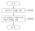
도 9는 본 발명이 적용되는 실시예로서, 참조 픽쳐 리스트를 생성하는 흐름도를 나타낸다.9 is a flowchart for generating a reference picture list according to an embodiment to which the present invention is applied.
복호 픽쳐 버퍼부(Decoded Picture Buffer unit)(600)에서는 화면간 예측을 수행하기 위해서 이전에 코딩된 픽쳐들을 저장하거나 개방하는 역할 등을 수행한다. 먼저, 현재 픽쳐 이전에 코딩된 픽쳐들은 참조 픽쳐로 활용하기 위하여 참조 픽쳐 저장부(610)에 저장된다(S91). 다시점 비디오 코딩에 있어서 상기 이전에 코딩된 픽쳐들 중에는 현재 픽쳐와 다른 시점에 있는 픽쳐들도 있으므로, 이러한 픽쳐들을 참조 픽쳐로서 활용하기 위해서는 픽쳐의 시점을 식별하는 시점 정보를 이 용할 수 있다. 따라서, 디코더에서는 픽쳐의 시점을 식별하는 시점 정보를 획득하여야 한다(S92). 예를 들어, 상기 시점 정보는 픽쳐의 시점을 식별하는 view_id 를 포함할 수 있다. 상기 복호 픽쳐 버퍼부(600)에서는 참조 픽쳐 리스트를 생성하기 위하여 상기 복호 픽쳐 버퍼부(600) 내에서 사용되는 변수를 유도할 필요가 있다. 다시점 비디오 코딩에 있어서는 시점간 예측이 이루어질 수 있으므로 현재 픽쳐가 다른 시점에 있는 픽쳐를 참조하게 되는 경우, 시점간 예측을 위한 참조 픽쳐 리스트를 생성할 필요가 있을 수 있다. 이 때, 상기 복호 픽쳐 버퍼부(600)에서는 상기 획득된 시점 정보를 이용하여, 시점간 예측을 위한 참조 픽쳐 리스트를 생성하기 위해 사용되는 변수를 유도할 필요가 있다(S93).The decoded
시간적 예측을 위한 참조 픽쳐 리스트 또는 시점간 예측을 위한 참조 픽쳐 리스트는 현재 슬라이스의 슬라이스 타입에 따라 다른 방식으로 생성될 수 있다(S94). 예를 들어, 슬라이스 타입이 P/SP 슬라이스인 경우에는 참조 픽쳐 리스트0를 생성하게 되고(S95), 슬라이스 타입이 B 슬라이스인 경우에는 참조 픽쳐 리스트0와 참조 픽쳐 리스트1을 생성하게 된다(S96). 이 때 참조 픽쳐 리스트 0 또는 참조 픽쳐 리스트 1은 시간적 예측을 위한 참조 픽쳐 리스트만을 포함할 수 있고, 또는 상기 시간적 예측을 위한 참조 픽쳐 리스트와 시점간 예측을 위한 참조 픽쳐 리스트를 모두 포함하고 있을 수 있다. 이에 대해서는 도 8 및 도 9에서 상세히 설명하도록 한다.A reference picture list for temporal prediction or a reference picture list for inter-view prediction may be generated in different ways according to the slice type of the current slice (S94). For example, when the slice type is a P / SP slice, a
이렇게 초기화된 참조 픽쳐 리스트는 보다 압축률을 향상시키기 위하여 빈번하게 참조된 픽쳐에 더 작은 번호를 할당하는 과정을 거치게 된다(S97). 이를 참조 픽쳐 리스트의 재배열 과정이라고 한다. 도 12 내지 도 19에서 상세히 설명하도록 한다. 이렇게 재배열된 참조 픽쳐 리스트를 이용하여 현재 픽쳐를 디코딩하게 되며, 상기 복호 픽쳐 버퍼부(600)에서는 버퍼를 보다 효율적으로 운영하기 위하여 디코딩된 참조 픽쳐들을 관리할 필요가 있다(S98). 이러한 과정을 통해 관리되는 참조 픽쳐들은 상기 인터 예측부(700)로부터 불러들여져 인터 예측을 위해 이용된다. 다시점 비디오 코딩에 있어서, 상기 인터 예측은 시점간 예측을 포함할 수 있으므로 이러한 경우에는 시점간 예측을 위한 참조 픽쳐 리스트가 이용될 수 있다.The initialized reference picture list is subjected to a process of allocating a smaller number to the frequently referenced pictures in order to improve the compression ratio (S97). This is called a rearrangement process of the reference picture list. 12 to 19 will be described in detail. The current picture is decoded using the rearranged reference picture list, and the decoded
이하 도 10 및 도 11에서는 슬라이스 타입에 따라 참조 픽쳐 리스트가 어떠한 방식으로 생성되는지 구체적인 실시예들을 통해서 알아보도록 한다.10 and 11 will be described with reference to specific embodiments of how the reference picture list is generated according to the slice type.
도 10은 본 발명이 적용되는 일실시예로서, 현재 슬라이스가 P슬라이스일 때의 참조 픽쳐 리스트를 초기화하는 방법을 설명하기 위해 나타낸 것이다.FIG. 10 is a diagram for explaining a method of initializing a reference picture list when a current slice is a P slice according to an embodiment to which the present invention is applied.
T0, T1, ...,TN 은 시간을 나타내고, V0, V1, ...,V4 는 시점을 나타낸다. 예를 들어, 현재 픽쳐(current picture)는 V4 시점의 T3 시간에 있는 픽쳐를 나타낸다. 또한 현재 픽쳐의 슬라이스 타입은 P 슬라이스인 경우이다. PN은 변수 PicNum의 약자이며, LPN은 변수 LongtermPicNum의 약자이며, VN은 변수 ViewNum의 약자이다. 각 변수 뒤에 붙은 숫자는 각 픽쳐의 시간(PN,LPN의 경우) 또는 시점(VN의 경우)을 가리키는 인덱스를 의미한다. 이는 도 11에서도 동일하게 적용된다.T0 , T1 , ..., TN represent time, and V0 , V1 , ..., V4 represent time points. For example, the current picture represents a picture at T3 time at the time V4 . In addition, the slice type of the current picture is a P slice. PN stands for variable PicNum, LPN stands for variable LongtermPicNum, and VN stands for variable ViewNum. The number after each variable means an index indicating a time (for PN or LPN) or a viewpoint (for VN) of each picture. The same applies to FIG. 11.
시간적 예측을 위한 참조 픽쳐 리스트 또는 시점간 예측을 위한 참조 픽쳐 리스트는 현재 슬라이스의 슬라이스 타입에 따라 다른 방식으로 생성될 수 있다. 예를 들어, 도 12에서는 슬라이스 타입이 P/SP 슬라이스인 경우로, 이 경우에는 참조 픽쳐 리스트0를 생성하게 된다. 여기서 상기 참조 픽쳐 리스트0는 시간적 예측을 위한 참조 픽쳐 리스트 및/또는 시점간 예측을 위한 참조 픽쳐 리스트를 포함할 수 있다. 본 실시예에서는 참조 픽쳐 리스트 0가 시간적 예측을 위한 참조 픽쳐 리스트와 시점간 예측을 위한 참조 픽쳐 리스트 모두를 포함하는 경우를 설명하도록 한다. 참조 픽쳐들을 배열하는 방법으로는 여러 가지가 있을 수 있는데, 예를 들어, 디코딩 순서에 따라 참조 픽쳐들을 배열할 수 있으며, 또는 픽쳐 출력 순서에 따라 참조 픽쳐들을 배열할 수도 있다. 또는 시점 정보를 이용하여 유도된 변수에 기초하여 배열될 수 있으며, 또는 시점 간의 예측 구조를 알 수 있는 시점간 참조 정보에 따라 참조 픽쳐들이 배열될 수도 있다.The reference picture list for temporal prediction or the reference picture list for inter-view prediction may be generated in different ways according to the slice type of the current slice. For example, in FIG. 12, when the slice type is a P / SP slice, the
시간적 예측을 위한 참조 픽쳐 리스트의 경우, 단기 참조 픽쳐와 장기 참조 픽쳐는 디코딩 순서에 기초하여 배열될 수 있다. 예를 들어, 픽쳐의 식별 번호를 나타내는 값(예를 들어, frame_num 또는 Longtermframeidx)으로부터 유도된 변수(PicNum 또는 LongtermPicNum)값에 따라 배열될 수 있다. 먼저 장기 참조 픽쳐에 앞서 단기 참조 픽쳐들이 초기화될 수 있다. 단기 참조 픽쳐의 배열되는 순서는 참조 픽쳐 중 가장 높은 변수(PicNum)값을 갖는 참조 픽쳐부터 가장 낮은 변수값을 갖는 참조 픽쳐의 순서로 배열될 수 있다. 예를 들어, PN0,PN1,PN2 중 가장 높은 변수를 갖는 PN1부터 시작하여, 그 다음에 PN2, 그 다음에 가장 낮은 변수를 갖는 PN0 순서로 배열될 수 있다. 장기 참조 픽쳐의 배열되는 순서는 참조 픽쳐 중 가장 낮은 변수(LongtermPicNum)값을 갖는 참조 픽쳐부터 가장 높은 변수값을 갖는 참조 픽쳐의 순서로 배열될 수 있다. 예를 들어, LPN0,LPN1 중 가장 낮은 변수를 갖는 LPN0부터 시작하여, 그 다음에 가장 낮은 변수를 갖는 LPN1 순서로 배열될 수 있다.In the case of a reference picture list for temporal prediction, the short-term reference picture and the long-term reference picture may be arranged based on the decoding order. For example, it may be arranged according to the value of a variable (PicNum or LongtermPicNum) derived from a value (eg, frame_num or Longtermframeidx) indicating an identification number of a picture. First, the short-term reference pictures may be initialized prior to the long-term reference picture. The order in which the short-term reference pictures are arranged may be arranged in order from the reference picture having the highest variable PicNum value among the reference pictures to the reference picture having the lowest variable value. For example, starting from PN1 having the highest variable of PN0, PN1, PN2, then PN2, then PN0 having the lowest variable, may be arranged. The order in which the long-term reference picture is arranged may be arranged in the order of the reference picture having the lowest variable (LongtermPicNum) value from the reference picture to the reference picture having the highest variable value. For example, starting from LPN0 having the lowest variable among LPN0, LPN1, it may then be arranged in LPN1 order having the lowest variable.
시점간 예측을 위한 참조 픽쳐 리스트의 경우, 시점 정보를 이용하여 유도된 제 1 변수(ViewNum)에 기초하여 배열될 수 있다. 예를 들어, 참조 픽쳐 중 가장 높은 제 1 변수(ViewNum)값을 갖는 참조 픽쳐부터 가장 낮은 변수값을 갖는 참조 픽쳐의 순서로 배열될 수 있다. 예를 들어, VN0,VN1,VN2,VN3 중 가장 높은 변수를 갖는 VN3부터 시작하여, 그 다음에 VN2,VN1, 그 다음에 가장 낮은 변수를 갖는 VN0 순서로 배열될 수 있다.In the case of a reference picture list for inter-view prediction, the reference picture list may be arranged based on the first variable ViewNum derived using the viewpoint information. For example, the reference picture may be arranged in order from the reference picture having the highest first ViewView value among the reference pictures to the reference picture having the lowest variable value. For example, it may be arranged starting from VN3 having the highest variable of VN0, VN1, VN2, VN3, and then in the order of VN2, VN1, then VN0 having the lowest variable.
이처럼, 상기 시간적 예측을 위한 참조 픽쳐 리스트와 상기 시점간 예측을 위한 참조 픽쳐 리스트는 하나의 참조 픽쳐 리스트로 관리될 수 있으며, 또는 별개의 참조 픽쳐 리스트로 각각 관리될 수도 있다. 그리고, 하나의 참조 픽쳐 리스트로 관리하게 되는 경우에는 순서에 따라 초기화될 수 있으며, 또는 동시에 초기화될 수도 있다. 순서에 따라 초기화되는 경우에는, 예를 들어, 상기 시간적 예측을 위한 참조 픽쳐 리스트를 먼저 초기화하고, 그 다음에 추가적으로 상기 시점간 예측을 위한 참조 픽쳐 리스트를 초기화할 수 있다. 이러한 개념은 도 11에서도 적용될 수 있다. 이하 도 11에서는 현재 픽쳐의 슬라이스 타입이 B 슬라이스인 경우에 대해 살펴보도록 한다.As such, the reference picture list for temporal prediction and the reference picture list for inter-view prediction may be managed as one reference picture list or may be managed as separate reference picture lists, respectively. In the case of managing one reference picture list, the information may be initialized in order or may be initialized at the same time. In the case of being initialized in order, for example, the reference picture list for the temporal prediction may be initialized first, and then the reference picture list for the inter-view prediction may be additionally initialized. This concept can also be applied to FIG. 11. Hereinafter, a case in which the slice type of the current picture is a B slice will be described.
도 11은 본 발명이 적용되는 일실시예로서, 현재 슬라이스가 B슬라이스일 때의 참조 픽쳐 리스트를 초기화하는 방법을 설명하기 위해 나타낸 것이다.FIG. 11 is a diagram for explaining a method of initializing a reference picture list when a current slice is a B slice as an embodiment to which the present invention is applied.
슬라이스 타입이 B 슬라이스인 경우에는 참조 픽쳐 리스트0와 참조 픽쳐 리스트1을 생성하게 된다. 이 때 참조 픽쳐 리스트 0 또는 참조 픽쳐 리스트 1은 시간적 예측을 위한 참조 픽쳐 리스트만을 포함할 수 있고, 또는 상기 시간적 예측을 위한 참조 픽쳐 리스트와 시점간 예측을 위한 참조 픽쳐 리스트를 모두 포함하고 있을 수 있다.If the slice type is a B slice,
먼저 시간적 예측을 위한 참조 픽쳐 리스트의 경우, 단기 참조 픽쳐와 장기 참조 픽쳐의 배열 방법이 다를 수 있다. 예를 들어, 단기 참조 픽쳐의 경우는 픽쳐 출력 순서(Picture Order Count, 이하 POC라 함)에 따라 참조 픽쳐들이 배열될 수 있고, 장기 참조 픽쳐의 경우는 변수(LongtermPicNum)값에 따라 참조 픽쳐들이 배열될 수 있다. 그리고, 장기 참조 픽쳐에 앞서 단기 참조 픽쳐들이 초기화될 수 있다.First, in the case of a reference picture list for temporal prediction, a method of arranging short-term reference pictures and long-term reference pictures may be different. For example, in the case of a short-term reference picture, reference pictures may be arranged according to a picture output order (hereinafter, referred to as a POC). In the case of a long-term reference picture, reference pictures may be arranged according to a variable (LongtermPicNum) value. Can be. The short-term reference pictures may be initialized before the long-term reference picture.
참조 픽쳐 리스트0의 단기 참조 픽쳐의 배열되는 순서는 현재 픽쳐보다 낮은 POC값을 갖는 참조 픽쳐 중 가장 높은 POC값을 갖는 참조 픽쳐부터 가장 낮은 POC값을 갖는 참조 픽쳐의 순서로 배열되고, 그 다음에 현재 픽쳐보다 높은 POC값을 갖는 참조 픽쳐 중 가장 낮은 POC값을 갖는 참조 픽쳐부터 가장 높은 POC값을 갖는 참조 픽쳐의 순서로 배열될 수 있다. 예를 들어, 현재 픽쳐보다 낮은 POC값을 갖는 참조 픽쳐인 PN0,PN1 중 가장 높은 POC값을 갖는 PN1부터 시작하여, PN0 순서로 배열되고, 그 다음에 현재 픽쳐보다 높은 POC값을 갖는 참조 픽쳐인 PN3,PN4 중 가장 낮은 POC값을 갖는 PN3부터 시작하여, PN4 순서로 배열될 수 있다.The order of the short-term reference pictures of
그리고 참조 픽쳐 리스트0의 장기 참조 픽쳐의 배열되는 순서는 참조 픽쳐 중 가장 낮은 변수(LongtermPicNum)를 갖는 참조 픽쳐부터 가장 높은 변수를 갖는 참조 픽쳐의 순서로 배열될 수 있다. 예를 들어, LPN0,LPN1 중 가장 낮은 변수를 갖는 LPN0부터 시작하여, 그 다음에 가장 낮은 변수를 갖는 LPN1 순서로 배열될 수 있다.The order in which the long-term reference pictures of the
시점간 예측을 위한 참조 픽쳐 리스트의 경우, 시점 정보를 이용하여 유도된 제 1 변수(ViewNum)에 기초하여 배열될 수 있다. 예를 들어, 시점간 예측을 위한 참조 픽쳐 리스트0의 경우 현재 픽쳐보다 낮은 제 1 변수값을 갖는 참조 픽쳐 중 가장 높은 제 1 변수값을 갖는 참조 픽쳐부터 가장 낮은 제 1 변수값을 갖는 참조 픽쳐의 순서로 배열될 수 있다. 그리고, 현재 픽쳐보다 높은 제 1 변수값을 갖는 참조 픽쳐 중 가장 낮은 제 1 변수값을 갖는 참조 픽쳐부터 가장 높은 제 1 변수값을 갖는 참조 픽쳐의 순서로 배열될 수 있다. 예를 들어, 현재 픽쳐보다 낮은 제 1 변수값을 갖는 참조 픽쳐인 VN0,VN1 중 가장 높은 제 1 변수값을 갖는 VN1부터 시작하여, 가장 낮은 제 1 변수값을 갖는 VN0 순서로 배열될 수 있다. 그 다음에 현재 픽쳐보다 높은 제 1 변수값을 갖는 참조 픽쳐인 VN3,VN4 중 가장 낮은 제 1 변수값을 갖는 VN3부터 시작하여, 가장 높은 제 1 변수값을 갖는 VN4 순서로 배열될 수 있다.In the case of a reference picture list for inter-view prediction, the reference picture list may be arranged based on the first variable ViewNum derived using the viewpoint information. For example, in the case of the
참조 픽쳐 리스트 1의 경우, 상기에서 설명한 참조 픽쳐 리스트 0의 배열 방식과 유사하게 적용될 수 있다.In the case of the
먼저 시간적 예측을 위한 참조 픽쳐 리스트의 경우, 참조 픽쳐 리스트1의 단기 참조 픽쳐의 배열되는 순서는 현재 픽쳐보다 높은 POC값을 갖는 참조 픽쳐 중 가장 낮은 POC값을 갖는 참조 픽쳐부터 가장 높은 POC값을 갖는 참조 픽쳐의 순서로 배열되고, 그 다음에 현재 픽쳐보다 낮은 POC값을 갖는 참조 픽쳐 중 가장 높은 POC값을 갖는 참조 픽쳐부터 가장 낮은 POC값을 갖는 참조 픽쳐의 순서로 배열될 수 있다. 예를 들어, 현재 픽쳐보다 높은 POC값을 갖는 참조 픽쳐인 PN3,PN4 중 가장 낮은 POC값을 갖는 PN3부터 시작하여, PN4 순서로 배열되고, 그 다음에 현재 픽쳐보다 낮은 POC값을 갖는 참조 픽쳐인 PN0,PN1 중 가장 높은 POC값을 갖는 PN1부터 시작하여, PN0 순서로 배열될 수 있다.First, in the case of the reference picture list for temporal prediction, the arrangement order of the short-term reference pictures of the
그리고 참조 픽쳐 리스트1의 장기 참조 픽쳐의 배열되는 순서는 참조 픽쳐 중 가장 낮은 변수(LongtermPicNum)를 갖는 참조 픽쳐부터 가장 높은 변수를 갖는 참조 픽쳐의 순서로 배열될 수 있다. 예를 들어, LPN0,LPN1 중 가장 낮은 변수를 갖는 LPN0부터 시작하여, 그 다음에 가장 낮은 변수를 갖는 LPN1 순서로 배열될 수 있다.The order in which the long-term reference pictures of the
시점간 예측을 위한 참조 픽쳐 리스트의 경우, 시점 정보를 이용하여 유도된 제 1 변수(ViewNum)에 기초하여 배열될 수 있다. 예를 들어, 시점간 예측을 위한 참조 픽쳐 리스트1의 경우 현재 픽쳐보다 높은 제 1 변수값을 갖는 참조 픽쳐 중 가장 낮은 제 1 변수값을 갖는 참조 픽쳐부터 가장 높은 제 1 변수값을 갖는 참조 픽쳐의 순서로 배열될 수 있다. 그리고, 현재 픽쳐보다 낮은 제 1 변수값을 갖는 참조 픽쳐 중 가장 높은 제 1 변수값을 갖는 참조 픽쳐부터 가장 낮은 제 1 변수값을 갖는 참조 픽쳐의 순서로 배열될 수 있다. 예를 들어, 현재 픽쳐보다 높은 제 1 변수값을 갖는 참조 픽쳐인 VN3,VN4 중 가장 낮은 제 1 변수값을 갖는 VN3부터 시 작하여, 가장 높은 제 1 변수값을 갖는 VN4 순서로 배열될 수 있다. 그 다음에 현재 픽쳐보다 낮은 제 1 변수값을 갖는 참조 픽쳐인 VN0,VN1중 가장 높은 제 1 변수값을 갖는 VN1부터 시작하여, 가장 낮은 제 1 변수값을 갖는 VN0 순서로 배열될 수 있다.In the case of a reference picture list for inter-view prediction, the reference picture list may be arranged based on the first variable ViewNum derived using the viewpoint information. For example, in the case of
상기와 같은 과정을 통해 초기화된 참조 픽쳐 리스트는 상기 참조 픽쳐 리스트 재배열부(640)로 전송되어 보다 효율적인 코딩을 위해 상기 초기화된 참조 픽쳐 리스트를 재배열하게 된다. 이러한 재배열 과정은 복호 픽쳐 버퍼를 운영하여 참조 픽쳐로서 선택될 확률이 가장 높은 참조 픽쳐에 낮은 번호를 할당하여 비트율을 줄이기 위한 것이다. 이하 도 12 내지 도 19에서는 참조 픽쳐 리스트를 재배열하는 방법을 다양한 실시예들을 통해 설명하도록 한다.The reference picture list initialized through the above process is transmitted to the reference picture
도 12는 본 발명이 적용되는 실시예로서, 참조 픽쳐 리스트 재배열부(640)의 내부 블록도를 나타낸다.12 is an embodiment to which the present invention is applied and shows an internal block diagram of the reference
참조 픽쳐 리스트 재배열부(640)는 크게 슬라이스 타입 확인부(642), 참조 픽쳐 리스트0 재배열부(643) 및 참조 픽쳐 리스트1 재배열부(645)를 포함한다. 상기 참조 픽쳐 리스트0 재배열부(643)는 제 1 식별정보 획득부(643A)와 제 1 참조번호 할당 변경부(643B)를 포함하고, 상기 참조 픽쳐 리스트1 재배열부(645)는 제 2 식별정보 획득부(645A)와 제 2 참조번호 할당 변경부(645B)를 포함한다.The reference picture
슬라이스 타입 확인부(642)는 현재 슬라이스의 슬라이스 타입을 확인하여, 상기 슬라이스 타입에 따라 참조 픽쳐 리스트0 및/또는 참조 픽쳐 리스트1의 재배열을 수행할지 여부가 결정된다. 예를 들어, 현재 슬라이스의 슬라이스 타입이 I슬 라이스인 경우 참조 픽쳐 리스트0 및 참조 픽쳐 리스트1 모두 재배열을 수행하지 않는다. 그리고, P슬라이스인 경우에는 참조 픽쳐 리스트0만에 대해 재배열을 수행하고, B슬라이스인 경우에는 참조 픽쳐 리스트0 및 참조 픽쳐 리스트1 모두에 대해 재배열을 수행한다.The slice
참조 픽쳐 리스트0 재배열부(643)는 상기 현재 슬라이스의 슬라이스 타입이 I슬라이스가 아니고, 상기 참조 픽쳐 리스트0의 재배열을 수행하라는 플래그 정보가 참일 경우에 동작한다. 제 1 식별정보 획득부(643A)는 참조번호의 할당 방법을 나타내는 식별 정보를 획득하고, 제 1 참조번호 할당 변경부(643B)에서는 상기 식별 정보에 따라 상기 참조 픽쳐 리스트0의 각 참조 픽쳐에 할당되는 참조 번호를 변경하게 된다.The
마찬가지로 참조 픽쳐 리스트1 재배열부(645)는 상기 현재 슬라이스의 슬라이스 타입이 B 슬라이스이고, 상기 참조 픽쳐 리스트1의 재배열을 수행하라는 플래그 정보가 참일 경우에 동작한다. 제 2 식별정보 획득부(645A)는 참조번호의 할당 방법을 나타내는 식별 정보를 획득하고, 제 2 참조번호 할당 변경부(645B)에서는 상기 식별 정보에 따라 상기 참조 픽쳐 리스트1의 각 참조 픽쳐에 할당되는 참조 번호를 변경하게 된다.Similarly, the reference picture list reordering unit 645 operates when the slice type of the current slice is a B slice and flag information for reordering the
상기 참조 픽쳐 리스트0 재배열부(643)와 상기 참조 픽쳐 리스트1 재배열부(645)를 통해 실제 인터 예측을 위해 사용되는 참조 픽쳐 리스트 정보가 생성된다. 이하 도 13에서는 상기 제 1,2 참조번호 할당 변경부(643B,645B)에서 각 참조 픽쳐에 할당되는 참조 번호를 변경하는 방법을 상세히 설명하도록 한다.Reference picture list information used for actual inter prediction is generated through the reference picture list reordering unit 643 and the reference picture list reordering unit 645. Hereinafter, a method of changing the reference number assigned to each reference picture by the first and second reference number
도 13은 본 발명이 적용되는 실시예로서, 참조번호 할당 변경부(643B,645B)의 내부 블록도를 나타낸다.FIG. 13 shows an internal block diagram of reference number
본 실시예에서는 상기 도 12에 나타난 참조 픽쳐 리스트0 재배열부(643)와 참조 픽쳐 리스트1 재배열부(645)를 함께 설명하도록 한다. 제 1,2 참조번호 할당 변경부(643B,645B)는 시간적 예측을 위한 참조번호 할당 변경부(644A), 장기 참조 픽쳐를 위한 참조번호 할당 변경부(644B), 시점간 예측을 위한 참조번호 할당 변경부(644C) 및 참조번호 할당 변경 종료부(644D)를 포함한다. 제 1,2 식별정보 획득부(643A,645A)에서 획득된 식별 정보에 따라 상기 제 1,2 참조번호 할당 변경부(643B,645B)내의 각 부분들이 동작하게 된다. 이러한 재배열 과정은 참조번호 할당 변경을 종료하라는 식별 정보가 들어올 때까지 수행된다.In the present embodiment, the
예를 들어, 상기 제 1,2 식별정보 획득부(643A,645A)에서 시간적 예측을 위한 참조 번호의 할당을 변경하라는 식별 정보가 전송된 경우, 상기 시간적 예측을 위한 참조번호 할당 변경부(644A)가 동작한다. 상기 시간적 예측을 위한 참조번호 할당 변경부(644A)에서는 상기 식별 정보에 따라 픽쳐 번호의 차이값을 획득한다. 여기서 픽쳐 번호의 차이값이란, 현재 픽쳐의 픽쳐 번호와 예측된 픽쳐 번호의 차이를 의미하고, 상기 예측된 픽쳐 번호란 직전에 할당된 참조 픽쳐의 번호를 의미할 수 있다. 이렇게 획득된 상기 픽쳐 번호의 차이값을 이용하여 참조번호의 할당을 변경할 수 있다. 이 때, 상기 픽쳐 번호의 차이값은 상기 식별 정보에 따라 상기 예측된 픽쳐 번호로부터 더해지거나 빼질 수 있다.For example, when identification information is transmitted from the first and second identification
다른 예로서, 지정한 장기 참조 픽쳐에 참조 번호의 할당을 변경하라는 식별 정보가 전송된 경우, 상기 장기 참조 픽쳐를 위한 참조번호 할당 변경부(644B)가 동작한다. 상기 장기 참조 픽쳐를 위한 참조번호 할당 변경부(644B)에서는 상기 식별 정보에 따라 지정된 픽쳐의 장기 참조 픽쳐 번호를 획득하게 된다.As another example, when identification information for changing the assignment of the reference number is transmitted to the designated long-term reference picture, the reference number
또 다른 예로서, 시점간 예측을 위한 참조 번호의 할당을 변경하라는 식별 정보가 전송된 경우, 상기 시점간 예측을 위한 참조번호 할당 변경부(644C)가 동작한다. 상기 시점간 예측을 위한 참조번호 할당 변경부(644C)에서는 상기 식별 정보에 따라 시점 정보의 차이값을 획득한다. 여기서 시점 정보의 차이값이란, 현재 픽쳐의 시점 번호와 예측된 시점 번호의 차이를 의미하고, 상기 예측된 시점 번호란 직전에 할당된 참조 픽쳐의 시점 번호를 의미할 수 있다. 이렇게 획득된 상기 시점 정보의 차이값을 이용하여 참조번호의 할당을 변경할 수 있다. 이 때, 상기 시점 정보의 차이값은 상기 식별 정보에 따라 상기 예측된 시점 번호로부터 더해지거나 빼질 수 있다.As another example, when identification information for changing the assignment of the reference number for the inter-view prediction is transmitted, the reference number
또 다른 예로서, 참조번호 할당 변경을 종료하라는 식별 정보가 전송된 경우, 상기 참조번호 할당변경 종료부(644D)가 동작한다. 상기 참조번호 할당변경 종료부(644D)에서는 상기 식별 정보에 따라 참조번호의 할당 변경을 종료하고, 그에 따라 상기 참조 픽쳐 리스트 재배열부(640)에서는 참조 픽쳐 리스트 정보를 생성하게 된다.As another example, when identification information for terminating a reference number assignment change is transmitted, the reference number assignment
이처럼, 시점간 예측에 이용되는 참조 픽쳐들은 시간적 예측에 이용되는 참조 픽쳐들과 함께 관리될 수 있다. 또는 시점간 예측에 이용되는 참조 픽쳐들을 시 간적 예측에 이용되는 참조 픽쳐들과는 별도로 관리할 수도 있다. 이러한 경우에는 상기 시점간 예측에 이용되는 참조 픽쳐들을 관리하기 위한 새로운 정보들이 필요할 수 있다. 이러한 경우에 대해서는 도 15내지 도 19에서 상세히 설명하도록 한다. 이하 도 14에서는 상기 시점간 예측을 위한 참조번호 할당 변경부(644C)에 대하여 구체적인 실시예를 통해 살펴보도록 한다.As such, reference pictures used for inter-view prediction may be managed together with reference pictures used for temporal prediction. Alternatively, reference pictures used for inter prediction may be managed separately from reference pictures used for temporal prediction. In this case, new information for managing reference pictures used for the inter-view prediction may be needed. This case will be described in detail with reference to FIGS. 15 to 19. Hereinafter, the reference number
도 14는 본 발명이 적용되는 일실시예로서, 시점 정보를 이용하여 참조 픽쳐 리스트를 재배열하는 과정을 설명하기 위해 나타낸 것이다.FIG. 14 is a diagram for explaining a process of rearranging a reference picture list using viewpoint information according to an embodiment to which the present invention is applied.
본 실시예에서는 현재 픽쳐의 시점 번호(VN)는 3, 복호 픽쳐 버퍼의 크기(DPBsize)는 4이고, 현재 슬라이스의 슬라이스 타입이 P슬라이스인 경우 참조 픽쳐 리스트0의 재배열 과정을 설명하도록 한다. 초기 예측된 시점 번호는 현재 픽쳐의 시점 번호인 3 이고, 시점간 예측을 위한 참조 픽쳐 리스트0의 최초 배열은 4,5,6,2 이다(①). 이 때, 시점 정보의 차이값을 감산하여 시점간 예측을 위한 참조 번호의 할당을 변경하라는 식별 정보가 전송되고, 상기 식별 정보에 따라 상기 시점 정보 차이값으로 1을 획득한다. 그리고 상기 예측된 시점 번호(=3)에 상기 시점 정보 차이값(=1)을 감산하여 새롭게 예측된 시점 번호(=2)가 계산된다. 즉, 시점 번호 2 를 가지는 참조 픽쳐에 시점간 예측을 위한 참조 픽쳐 리스트0의 첫번째 인덱스를 할당한다. 그리고, 이전의 첫번째 인덱스에 할당되어 있던 픽쳐는 상기 참조 픽쳐 리스트0의 제일 뒷부분으로 옮겨질 수 있다. 따라서, 재배열된 상기 참조 픽쳐 리스트0는 2,5,6,4 이다(②). 그 다음에, 다시 시점 정보의 차이값을 감산하여 시점간 예측을 위한 참조 번호의 할당을 변경하라는 식별 정보가 전송되고, 상기 식별 정보에 따라 상기 시점 정보 차이값으로 -2 를 획득한다. 그리고 상기 예측된 시점 번호(=2)에 상기 시점 정보 차이값(= -2)을 감산하여 새롭게 예측된 시점 번호(=4)가 계산된다. 즉, 시점 번호 4 를 가지는 참조 픽쳐에 시점간 예측을 위한 참조 픽쳐 리스트0의 두번째 인덱스를 할당한다. 따라서, 재배열된 상기 참조 픽쳐 리스트0는 2,4,6,5 이다(③). 그 다음에는, 참조번호 할당 변경을 종료하라는 식별 정보가 전송된 경우, 상기 식별 정보에 따라 상기 재배열된 참조 픽쳐 리스트0를 끝으로 참조 픽쳐 리스트0가 생성된다(④). 결국 최종 생성된 시점간 예측을 위한 참조 픽쳐 리스트0의 배열은 2,4,6,5 이다.In the present embodiment, when the view number VN of the current picture is 3, the size of the decoded picture buffer is 4, and the slice type of the current slice is P slice, the rearrangement process of the
시점간 예측을 위한 참조 픽쳐 리스트0의 첫번째 인덱스를 할당한 후 나머지 픽쳐들을 재배열하는 다른 예로서, 각 인덱스에 할당되어 있던 픽쳐가 차례로 바로 뒤의 위치로 옮겨질 수 있다. 즉, 시점 번호가 4인 픽쳐에는 두번째 인덱스를 할당하고, 두번째 인덱스가 할당되어 있던 시점 번호 5인 픽쳐에는 세번째 인덱스를 할당하며, 세번째 인덱스가 할당되어 있던 시점 번호 6인 픽쳐에는 네번째 인덱스를 할당할 수 있게 된다. 따라서, 재배열된 상기 참조 픽쳐 리스트0는 2,4,5,6 이 된다. 이후 재배열되는 과정도 동일하게 적용시킬 수 있다.As another example of rearranging the remaining pictures after allocating the first index of the
상기와 같은 과정을 거쳐 생성된 참조 픽쳐 리스트는 인터 예측에 사용된다. 시점간 예측을 위한 참조 픽쳐 리스트는 시간적 예측을 위한 참조 픽쳐 리스트와 함께 하나의 참조 픽쳐 리스트로 관리될 수 있다. 또한, 별개의 참조 픽쳐 리스트로 관리될 수도 있는데, 이에 대해서는 도 15 내지 도 19에서 살펴보도록 한다.The reference picture list generated through the above process is used for inter prediction. The reference picture list for inter-view prediction may be managed as one reference picture list together with the reference picture list for temporal prediction. In addition, it may be managed as a separate reference picture list, which will be described with reference to FIGS. 15 to 19.
도 15는 본 발명이 적용되는 다른 실시예로서, 참조 픽쳐 리스트 재배열 부(640)의 내부 블록도를 나타낸다.15 is a block diagram of an internal reference picture
시점간 예측을 위한 참조 픽쳐 리스트를 별개의 참조 픽쳐 리스트로 관리하기 위해서는 새로운 정보들이 필요할 수 있다. 예를 들어, 먼저 시간적 예측을 위한 참조 픽쳐 리스트를 재배열하고, 경우에 따라서 시점간 예측을 위한 참조 픽쳐 리스트를 재배열하도록 구성할 수 있다.New information may be needed to manage the reference picture list for inter-view prediction as a separate reference picture list. For example, first, the reference picture list for temporal prediction may be rearranged, and in some cases, the reference picture list for inter-view prediction may be rearranged.
본 실시예에서 참조 픽쳐 리스트 재배열부(640)는 크게, 시간적 예측을 위한 참조 픽쳐 리스트 재배열부(910)와 NAL 타입 확인부(960) 및 시점간 예측을 위한 참조 픽쳐 리스트 재배열부(970)를 포함한다. 그리고, 상기 시간적 예측을 위한 참조 픽쳐 리스트 재배열부(910)는 슬라이스 타입 확인부(642), 제 3 식별정보 획득부(920), 제 3 참조번호 할당 변경부(930), 제 4 식별정보 획득부(940), 제 4 참조번호 할당 변경부(950)을 포함한다. 상기 제 3 참조번호 할당 변경부(930)는 시간적 예측을 위한 참조번호 할당 변경부(930A), 장기 참조 픽쳐를 위한 참조번호 할당 변경부(930B) 및 참조번호 할당변경 종료부(930C)를 포함한다. 마찬가지로 상기 제 4 참조번호 할당 변경부(950)는 시간적 예측을 위한 참조번호 할당 변경부(950A), 장기 참조 픽쳐를 위한 참조번호 할당 변경부(950B) 및 참조번호 할당변경 종료부(950C)를 포함한다.In the present embodiment, the reference
시간적 예측을 위한 참조 픽쳐 리스트 재배열부(910)는 시간적 예측에 이용되는 참조 픽쳐들을 재배열한다. 상기 시간적 예측을 위한 참조 픽쳐 리스트 재배열부(910)에서의 동작은 상기 도 12에서 설명한 참조 픽쳐 리스트 재배열부(640)에서 시점간 예측을 위한 참조 픽쳐에 관한 정보들을 제외하면, 그 동작이 동일하다. 따라서, 상기 도 12로부터 유추가능하므로 이에 대한 설명은 생략하기로 한다.The reference picture list rearranger 910 for temporal prediction rearranges reference pictures used for temporal prediction. The operation of the reference picture list rearranger 910 for temporal prediction is identical to the operation of the reference
NAL 타입 확인부(960)에서는 전송된 비트스트림의 NAL 타입을 확인한다. 상기 NAL 타입이 다시점 영상 코딩을 위한 NAL 인 경우, 시점간 예측을 위한 참조픽쳐 리스트 재배열부(970)를 통해 시점간 예측에 이용되는 참조 픽쳐들을 재배열하게 된다. 이렇게 생성된 시점간 예측을 위한 참조픽쳐 리스트는 시간적 예측을 위한 참조픽쳐 리스트 재배열부(910)을 통해 생성된 시간적 예측을 위한 참조픽쳐 리스트와 함께 인터 예측을 위해 사용된다. 그러나, 상기 NAL 타입이 다시점 영상 코딩을 위한 NAL 이 아닌 경우에는 시점간 예측을 위한 참조픽쳐 리스트를 재배열하지 않는다. 이 경우에는 단지 시간적 예측을 위한 참조 픽쳐 리스트만 생성된다. 그리고, 시점간 예측을 위한 참조픽쳐 리스트 재배열부(970)는 시점간 예측에 이용되는 참조 픽쳐들을 재배열하게 된다. 이는 도 16에서 상세히 설명하도록 한다.The NAL
도 16은 본 발명이 적용되는 실시예로서, 시점간 예측을 위한 참조 픽쳐 리스트 재배열부(970)의 내부 블록도를 나타낸다.FIG. 16 is a block diagram illustrating a reference
시점간 예측을 위한 참조 픽쳐 리스트 재배열부(970)는 슬라이스 타입 확인부(642), 제 5 식별정보 획득부(971), 제 5 참조번호 할당 변경부(972), 제 6 식별정보 획득부(973) 및 제 6 참조번호 할당 변경부(974)를 포함한다.The reference picture
슬라이스 타입 확인부(642)는 현재 슬라이스의 슬라이스 타입을 확인하여, 상기 슬라이스 타입에 따라 참조 픽쳐 리스트0 및/또는 참조 픽쳐 리스트1의 재배열을 수행할지 여부가 결정된다. 상기 슬라이스 타입 확인부(642)에 대한 자세한 설명은 상기 도 12로부터 유추가능하므로 생략하기로 한다.The slice
제 5,6 식별정보 획득부(971,973)는 참조번호의 할당 방법을 나타내는 식별 정보를 획득하고, 제 5,6 참조번호 할당 변경부(972,974)에서는 각각 상기 식별 정보에 따라 상기 참조 픽쳐 리스트0,1의 각 참조 픽쳐에 할당되는 참조 번호를 변경하게 된다. 여기서의 참조번호는 참조 픽쳐의 시점 번호만을 의미할 수 있다. 또한, 상기 참조번호의 할당 방법을 나타내는 식별 정보는 플래그 정보일 수 있다. 예를 들어, 플래그 정보가 참일 경우에는 시점 번호의 할당을 변경하고, 거짓일 경우에는 시점 번호의 재배열 과정을 종료할 수 있다. 만약 상기 플래그 정보가 참일 경우, 상기 제 5,6 참조번호 할당 변경부(972,974)는 상기 플래그 정보에 따라 시점 번호의 차이값을 획득할 수 있다. 여기서 시점 번호의 차이값이란, 현재 픽쳐의 시점 번호와 예측된 픽쳐의 시점 번호 사이의 차이를 의미하고, 상기 예측된 픽쳐의 시점 번호란 직전에 할당된 참조 픽쳐의 시점 번호를 의미할 수 있다. 이렇게 획득된 상기 시점 번호의 차이값을 이용하여 시점 번호의 할당을 변경할 수 있다. 이 때, 상기 시점 번호의 차이값은 상기 식별 정보에 따라 상기 예측된 픽쳐의 시점 번호로부터 더해지거나 빼질 수 있다.The fifth and sixth identification
이처럼, 시점간 예측을 위한 참조 픽쳐 리스트를 별개의 참조 픽쳐 리스트로 관리하기 위해서는 그 신택스 구조 또한 새롭게 정의할 필요가 있다. 따라서, 도 15와 도 16에서 설명한 내용에 대한 일실시예로서, 도 17,18 및 도 19에서는 그 신택스를 설명한다.As such, in order to manage the reference picture list for inter-view prediction as a separate reference picture list, the syntax structure needs to be newly defined. Therefore, as an embodiment of the contents described with reference to FIGS. 15 and 16, the syntax thereof will be described with reference to FIGS. 17, 18 and 19.
도 17 및 도 18은 본 발명이 적용되는 일실시예로서, 참조 픽쳐 리스트 재배열을 위한 신택스를 나타낸다.17 and 18 illustrate syntax for reordering reference picture lists as an embodiment to which the present invention is applied.
도 17은 상기 도 15에서 나타낸 시간적 예측을 위한 참조픽쳐 리스트 재배열부(910)의 동작을 신택스로 나타낸 것이다. 상기 도 15의 각 블록들과 비교해보면, 상기 슬라이스 타입 확인부(642)는 (S1),(S6)에 해당되고, 상기 제 3 식별정보 획득부(920)은 (S2), 상기 제 4 식별정보 획득부(940)은 (S7)에 해당된다. 그리고, 상기 제 3 참조번호 할당 변경부(930)의 내부 블록도들은 각각 (S3),(S4),(S5)에 해당되고, 상기 제 4 참조번호 할당 변경부(950)의 내부 블록도들은 각각 (S8),(S9),(S10)에 해당된다.FIG. 17 is a syntax diagram illustrating an operation of the reference picture list rearranger 910 for temporal prediction shown in FIG. 15. Compared with the blocks of FIG. 15, the slice
도 18은 상기 도 15 및 도 16에서 나타낸 NAL 타입 확인부(960)와 시점간 예측을 위한 참조픽쳐 리스트 재배열부(970)의 동작을 신택스로 나타낸 것이다. 상기 도 15와 도 16의 각 블록들과 비교해보면, 상기 NAL 타입 확인부(960)는 (S11)에 해당되고, 상기 슬라이스 타입 확인부(642)는 (S13),(S16)에 해당되고, 상기 제 5 식별정보 획득부(971)는 (S14), 상기 제 6 식별정보 획득부(973)는 (S17)에 해당된다. 그리고, 상기 제 5 참조번호 할당 변경부(972)는 (S15)에 해당되고, 상기 제 6 참조번호 할당 변경부(974)는 (S18)에 해당된다.18 is a syntax diagram illustrating operations of the NAL
도 19는 본 발명이 적용되는 다른 일실시예로서, 참조 픽쳐 리스트 재배열을 위한 신택스를 나타낸다.19 illustrates syntax for reordering reference picture lists, according to another embodiment to which the present invention is applied.
도 19는 상기 도 15 및 도 16에서 나타낸 NAL 타입 확인부(960)와 시점간 예측을 위한 참조픽쳐 리스트 재배열부(970)의 동작을 다른 신택스의 예로 나타낸 것이다. 상기 도 15와 도 16의 각 블록들과 비교해보면, 상기 NAL 타입 확인부(960)는 (S21)에 해당되고, 상기 슬라이스 타입 확인부(642)는 (S22),(S25)에 해당되고, 상기 제 5 식별정보 획득부(971)는 (S23), 상기 제 6 식별정보 획득부(973)는 (S26)에 해당된다. 그리고, 상기 제 5 참조번호 할당 변경부(972)는 (S24)에 해당되고, 상기 제 6 참조번호 할당 변경부(974)는 (S27)에 해당된다.19 illustrates an example of another syntax of operations of the NAL
위에서 살펴본 바와 같이, 시점간 예측을 위한 참조 픽쳐 리스트는 인터 예측부(700)에서 이용될 수 있는데, 휘도 보상을 수행함에 있어서도 적용이 가능할 수 있다. 휘도 보상은 움직임 추정/움직임 보상을 수행하는 과정에서 적용될 수 있는데, 이때 현재 픽쳐가 다른 시점에 있는 참조 픽쳐를 이용하게 되는 경우 상기 시점간 예측을 위한 참조 픽쳐 리스트를 이용함으로써 보다 효율적인 휘도 보상을 수행할 수 있다. 이하 위한 본 발명을 적용한 휘도 보상의 실시예들을 살펴보도록 한다.As described above, the reference picture list for inter-view prediction may be used by the
도 20은 본 발명이 적용되는 일실시예로서, 현재 블록의 휘도 차분 값을 획득하는 과정을 설명하기 위한 도면을 나타낸다.20 is a diagram for describing a process of obtaining a luminance difference value of a current block according to an embodiment to which the present invention is applied.
휘도 보상은 휘도 변이에 따라서 적응적으로 움직임 보상된 비디오 신호를 복호화하는 과정을 의미하며, 비디오 신호의 예측 구조가 인터 뷰 예측, 인트라 뷰 예측 등에 적용될 수 있다.Luminance compensation refers to a process of decoding a video signal that is adaptively motion compensated according to luminance variation, and the prediction structure of the video signal may be applied to inter-view prediction, intra-view prediction, and the like.
휘도 보상은 복호 대상이 되는 블록에 대응하는 휘도 차분 레지듀얼과, 휘도 차분 예측값을 이용하여 비디오 신호를 복호화하는 과정을 의미한다. 여기서, 휘도 차분 예측값은 복호 대상이 되는 블록에 존재하는 주변 블록으로부터 획득된다. 또한, 주변 블록으로부터 휘도 차분 예측값을 획득하는 과정은 주변 블록의 참조 정보를 이용하여 결정하되, 주변 블록을 탐색하는 과정에서 순서 및 방향이 고려된 다. 마지막으로, 주변 블록은 이미 복호화된 블록을 의미하되, 시점 또는 시간에 대한 동일 픽쳐 내의 중복성을 고려하여 복호화된 영상 혹은 서로 다른 픽쳐 내의 중복성을 고려하여 복호화된 영상을 의미한다.Luminance compensation refers to a process of decoding a video signal using a luminance difference residual corresponding to a block to be decoded and a luminance difference prediction value. Here, the luminance difference prediction value is obtained from neighboring blocks existing in the block to be decoded. In addition, the process of obtaining the luminance difference prediction value from the neighboring block is determined using the reference information of the neighboring block, but the order and the direction are taken into consideration in the process of searching the neighboring block. Lastly, the neighboring block refers to a block that has already been decoded, and refers to an image decoded in consideration of redundancy in the same picture with respect to a viewpoint or time, or a decoded image in consideration of redundancy in different pictures.
현재 블록과 후보 참조 블록(candidate reference block)의 유사성을 비교할 때 양 블록 사이의 휘도 차이를 고려하여야 한다. 상기 휘도 차이를 보상하기 위하여 새로운 움직임 추정/움직임 보상(motion compensation)이 수행된다. 새로운 SAD는 다음 수학식 1을 이용하여 구할 수 있다.When comparing the similarity between the current block and the candidate reference block, the luminance difference between the two blocks should be considered. New motion estimation / motion compensation is performed to compensate for the luminance difference. The new SAD can be obtained using
수학식 1

수학식 2

여기서, Mcurr는 현재 블록의 평균 화소값을 나타내고, Mref 는 참조 블록의 평균 화소값을 나타낸다. f(i,j) 는 현재 블록의 화소값을 나타내고, r(i+x, j+y) 는 참조 블록의 화소값를 나타낸다. 상기 수학식 2의 새로운 SAD에 기초하여 움직임 추정을 수행함으로써 상기 현재 블록과 상기 참조 블록 사이의 평균 화소값 차 이가 획득될 수 있다. 상기 획득된 평균 화소값 차이를 휘도 차분값(IC_offset)이라 한다.Where Mcurr Denotes an average pixel value of the current block, and Mref denotes an average pixel value of the reference block. f (i, j) represents the pixel value of the current block, and r (i + x, j + y) represents the pixel value of the reference block. By performing motion estimation based on the new SAD of
휘도 보상이 적용된 움직임 추정이 수행되는 경우, 휘도 차분 값과 움직임 벡터가 구해지고 휘도 보상은 상기 휘도 차분 값과 상기 움직임 벡터를 이용하여 수학식 3과 같이 수행된다.When motion estimation with luminance compensation is performed, a luminance difference value and a motion vector are obtained, and luminance compensation is performed using
수학식 3

여기서, NewR(i,j)는 휘도 보상이 수행된 오차값(residual)을 나타내고, (x', y')는 움직임 벡터를 나타낸다.Here, NewR (i, j) represents an error value (residual) in which luminance compensation is performed, and (x ', y') represents a motion vector.
휘도 차분 값(Mcurr-Mref)은 디코딩 장치로 전송되어야 한다. 디코딩 장치에서의 휘도 보상은 다음과 같이 수행된다.The luminance difference value Mcurr -Mref must be transmitted to the decoding apparatus. Luminance compensation in the decoding apparatus is performed as follows.
수학식 4

NewR"(i,j)는 복원된, 휘도 보상이 수행된 오차값(residual)을 나타내고, f'(i,j)는 복원된 현재 블록의 화소값을 나타낸다.NewR " (i, j) represents a reconstructed error value for which luminance compensation has been performed, and f '(i, j) represents a pixel value of the restored current block.
현재 블록을 복원하기 위해서는 휘도 차분 값이 디코딩 장치에 전송되어야 하고, 상기 휘도 차분 값은 이웃 블록들의 정보로부터 예측될 수 있다. 상기 휘도 차분 값을 코딩할 비트수를 더 감소시키기 위하여, 현재 블록의 휘도 차분 값(IC_offset)과 이웃 블록의 휘도 차분 값(predIC_offset)과의 차이값(RIC_offset)만 보낼 수 있다. 이는 아래 수학식 5와 같다.In order to recover the current block, a luminance difference value must be transmitted to the decoding apparatus, and the luminance difference value can be predicted from information of neighboring blocks. To further reduce the number of bits for encoding the luminance difference value, it is possible only to send the difference value (RIC_offset) of the luminance difference between the current block value (IC_offset) and the luminance difference value of the neighboring blocks (predIC_offset). This is shown in
수학식 5

도 21은 본 발명이 적용되는 실시예로서, 현재 블록에 대한 휘도 보상을 수행하는 과정을 설명하기 위한 흐름도를 나타낸다.FIG. 21 is a flowchart illustrating a process of performing luminance compensation on a current block according to an embodiment to which the present invention is applied.
먼저 비디오 신호로부터, 현재 블록의 이웃 블록과 상기 이웃 블록이 참조하는 블록의 평균 화소값 차이를 나타내는 상기 이웃 블록의 휘도 차분값을 추출한다(S2110). 상기 휘도 차분값을 이용하여 상기 현재 블록의 휘도 차분 예측값을 획득한다(S2120). 상기 획득된 휘도 차분 예측값을 이용하여 상기 현재 블록의 휘도 차분값을 복원할 수 있게 된다.First, the luminance difference value of the neighboring block representing the difference between the average pixel values of the neighboring block of the current block and the block referred to by the neighboring block is extracted (S2110). A luminance difference prediction value of the current block is obtained using the luminance difference value (S2120). The luminance difference value of the current block may be restored using the obtained luminance difference prediction value.
이 때, 상기 휘도 차분 예측값을 획득함에 있어서 다양한 방법으로 접근할 수 있다. 예를 들어, 상기 이웃 블록의 휘도 차분 값으로부터 상기 현재 블록의 휘도 차분 값을 예측하기에 앞서 현재 블록의 참조 번호(reference index)와 상기 이웃 블록의 참조 번호가 동일한지 여부를 확인하고, 그 확인 결과에 따라 어떤 이웃 블록을 이용할지, 또는 어떤 값을 이용할지가 결정될 수 있다. 또한, 이웃 블록의 정보를 탐색하는 과정에서 순서 또는 방향이 주어질 수 있으며, 정해진 순서 또는 방향에 따라 휘도 보상에 필요한 휘도 차분 예측값을 획득할 수도 있다. 다른 예로, 상기 휘도 차분 예측값을 획득할 때, 상기 현재 블록의 휘도 보상 수행 여부를 나타내는 플래그 정보(IC_flag)도 이용할 수 있다. 상기 현재 블록의 플래그 정보도 이웃 블록들의 정보를 이용하여 예측할 수 있다. 또 다른 예로, 상기 참조 번호를 확인하는 방법과 플래그 정보를 예측하는 방법 모두를 이용하여 상기 휘도 차분 예측값을 획득할 수도 있다. 이하 도 22 내지 도 24에서 상세하게 설명하기로 한다.In this case, various methods may be used to obtain the luminance difference prediction value. For example, before predicting the luminance difference value of the current block from the luminance difference value of the neighboring block, it is determined whether a reference index of the current block and the reference number of the neighboring block are the same, and the confirmation The result may determine which neighboring block to use or what value to use. In addition, an order or direction may be given in a process of searching for information of a neighboring block, and a luminance difference prediction value required for luminance compensation may be obtained according to a predetermined order or direction. As another example, when obtaining the luminance difference prediction value, flag information IC_flag indicating whether the current block performs luminance compensation may also be used. Flag information of the current block may also be predicted using information of neighboring blocks. As another example, the luminance difference prediction value may be obtained using both the method of confirming the reference number and the method of predicting flag information. Hereinafter, a detailed description will be given with reference to FIGS. 22 to 24.
도 22는 본 발명이 적용되는 일실시예로서, 이웃 블록의 정보를 이용하여 현재 블록의 휘도 차분 예측값을 획득하는 과정을 설명하기 위한 도면을 나타낸다.FIG. 22 is a diagram for describing a process of obtaining a luminance difference prediction value of a current block by using information of a neighboring block, according to an embodiment to which the present invention is applied.
현재 블록의 휘도 차분 예측값을 획득할 때 이웃 블록의 정보를 이용할 수 있다. 본 명세서에서 블록이라 함은 매크로블록 또는 서브매크로블록을 모두 포함한다. 예를 들어, 상기 이웃 블록의 휘도 차분 값을 이용하여 상기 현재 블록의 휘도 차분 값을 예측할 수 있는데, 이에 앞서 현재 블록의 참조 번호(reference index)와 상기 이웃 블록의 참조 번호가 동일한지 여부를 확인하고, 그 확인 결과에 따라 어떤 이웃 블록을 이용할지, 또는 어떤 값을 이용할지가 결정될 수 있다. "refIdxLX" 는 현재 블록의 참조 번호를 나타내고, "refIdxLXN" 은 N 블록의 참조 번호를 나타내며, 여기서 N은 현재 블록에 이웃한 블록의 표시로서 A, B or C 를 나타낸다. "PredIC_offsetN" 은 이웃한 N 블록의 휘도 보상을 위한 휘도 차분 값을 나타낸다. 여기서, 현재 블록의 우측 상단에 있는 블록인 C 블록을 이용할 수 없는 경우, C 블록 대신 D 블록을 사용할 수 있다. 즉, D 블록에 대한 정보를 C 블록에 대한 정보로 사용할 수 있다. 또한, B 블록과 C 블록을 모두 이용할 수 없는 경우, 대신하여 A 블록을 사용할 수 있다. 즉, A 블록에 대한 정보를 각각 B 블록에 대한 정보, C 블록에 대한 정보로 사용할 수 있다.When the luminance difference prediction value of the current block is obtained, information of the neighboring block may be used. In the present specification, a block includes both a macroblock or a submacroblock. For example, the luminance difference value of the current block may be predicted by using the luminance difference value of the neighboring block. Before this, it is determined whether the reference number of the current block and the reference number of the neighboring block are the same. According to the result of the checking, it is possible to determine which neighboring block to use or what value to use. "refIdxLX" represents the reference number of the current block, "refIdxLXN" represents the reference number of the N block, where N represents A, B or C as an indication of a block neighboring the current block. "PredIC_offset N" represents a luminance difference value for luminance compensation of neighboring N blocks. Here, when the C block, which is the block on the upper right side of the current block, is not available, the D block may be used instead of the C block. That is, the information about the D block may be used as the information about the C block. In addition, when neither B block nor C block is available, A block can be used instead. That is, the information about the A block may be used as the information about the B block and the information about the C block, respectively.
다른 예로, 상기 휘도 차분 예측값을 획득할 때, 상기 현재 블록의 휘도 보상 수행 여부를 나타내는 플래그 정보(IC_flag)도 이용할 수 있다. 또는 상기 참조 번호를 확인하는 방법과 플래그 정보를 예측하는 방법 모두를 이용하여 상기 휘도 차분 예측값을 획득할 수도 있다. 이 때, 상기 이웃 블록의 플래그 정보가 휘도 보상을 수행하지 않았음을 나타내는 경우, 즉 IC_flag == 0 인 경우 상기 이웃 블록의 휘도 차분값인 PredIC_offsetN 는 0 으로 셋팅된다.As another example, when obtaining the luminance difference prediction value, flag information IC_flag indicating whether the current block performs luminance compensation may also be used. Alternatively, the luminance difference prediction value may be obtained using both the method of confirming the reference number and the method of predicting flag information. At this time, if the flag information of the neighboring block to indicate that the IC is not performed, that is IC_flag == 0 if the luminance difference value of PredIC_ Noffset of the neighboring block are set to zero.
도 23은 본 발명이 적용되는 일실시예로서, 이웃 블록의 정보를 이용하여 휘도 보상을 수행하는 과정을 나타내는 흐름도이다.FIG. 23 is a flowchart illustrating a process of performing luminance compensation using information of a neighbor block according to an embodiment to which the present invention is applied.
디코딩 장치에서는 휘도 보상을 수행하기 위하여 비디오 신호로부터 참조 블록의 평균 화소값, 상기 현재 블록과 상기 참조 블록의 참조 번호 등을 추출하고, 이러한 정보들을 이용하여 현재 블록의 휘도 차분 예측값을 획득할 수 있다. 그리고, 현재 블록의 휘도 차분 값과 상기 휘도 차분 예측값 사이의 차이값인 휘도 차분 레지듀얼을 획득하고, 상기 획득된 휘도 차분 레지듀얼과 상기 휘도 차분 예측값을 이용하여 상기 현재 블록의 휘도 차분 값을 복원할 수 있다. 이때, 현재 블록의 휘도 차분 예측값을 획득함에 있어서, 이웃 블록의 정보를 이용할 수 있다. 예 를 들어, 상기 이웃 블록의 휘도 차분 값을 이용하여 상기 현재 블록의 휘도 차분 값을 예측할 수 있는데, 이에 앞서 현재 블록의 참조 번호(reference index)와 상기 이웃 블록의 참조 번호가 동일한지 여부를 확인하고, 그 확인 결과에 따라 어떤 이웃 블록을 이용할지, 또는 어떤 값을 이용할지가 결정될 수 있다.In order to perform luminance compensation, the decoding apparatus may extract an average pixel value of the reference block, reference numbers of the current block and the reference block, and the like from the video signal, and obtain the luminance difference prediction value of the current block by using the information. . And obtain a luminance difference residual, which is a difference between the luminance difference value of the current block and the luminance difference prediction value, and restore the luminance difference value of the current block by using the obtained luminance difference residual and the luminance difference prediction value. can do. In this case, in obtaining the luminance difference prediction value of the current block, information of the neighboring block may be used. For example, the luminance difference value of the current block may be predicted using the luminance difference value of the neighboring block. Before this, it is determined whether the reference number of the current block is the same as the reference number of the neighboring block. According to the result of the checking, it is possible to determine which neighboring block to use or what value to use.
그 구체적 실시예로, 현재 블록의 이웃 블록과 상기 이웃 블록이 참조하는 블록의 평균 화소값 차이를 나타내는 상기 이웃 블록의 휘도 차분값을 비디오 신호로부터 추출한다(S2310). 현재 블록의 참조 번호와 이웃 블록들의 참조 번호가 동일한지 여부를 확인한다(S2320). 확인 결과, 현재 블록의 참조 번호와 동일한 참조 번호를 가지는 이웃 블록이 존재하는 경우, 그 이웃 블록이 1개만 존재하는지 여부를 확인한다(S2325). 확인 결과, 현재 블록의 참조 번호와 동일한 참조 번호를 가지는 이웃 블록이 1개만 존재하는 경우, 상기 참조 번호가 동일한 이웃 블록의 휘도 차분 값을 현재 블록의 휘도 차분 예측값에 할당하게 된다(S2330). 즉, "PredIC_offset= PredIC_offsetN" 이 된다. 상기 S2320 단계의 확인 결과에 따라 현재 블록의 참조 번호와 동일한 참조 번호를 가지는 이웃 블록이 존재하지 않는 경우 또는 상기 S2325 단계의 확인 결과에 따라 현재 블록의 참조 번호와 동일한 참조 번호를 가지는 이웃 블록이 2이상 존재하는 경우에는 상기 이웃 블록들의 휘도 차분 값들(PredIC_offsetN, N = A, B or C)의 중간값(Median)을 현재 블록의 휘도 차분 예측값에 할당하게 된다(S2340). 즉, "PredIC_offset= Median(PredIC_offsetA, PredIC_offsetB, PredIC_offsetC)" 이 된다.In a specific embodiment, the luminance difference value of the neighboring block representing the difference in average pixel values between the neighboring block of the current block and the block referenced by the neighboring block is extracted from the video signal (S2310). In operation S2320, it is determined whether a reference number of the current block and a reference number of neighboring blocks are the same. As a result of the check, if there is a neighboring block having the same reference number as that of the current block, it is checked whether only one neighboring block exists (S2325). As a result of the check, when only one neighboring block having the same reference number as the reference number of the current block exists, the luminance difference value of the neighboring block having the same reference number is allocated to the luminance difference prediction value of the current block (S2330). That is, the"Pred IC_offset = Pred IC _ offset N". If there is no neighbor block having the same reference number as the reference number of the current block according to the check result of step S2320 or if the neighboring block having the same reference number as the reference number of the current block according to the check result of step S2325 is 2 If there is an error, the median value of the luminance difference values (PredIC_offset N, N = A, B or C) of the neighboring blocks is allocated to the luminance difference prediction value of the current block (S2340). That is, "PredIC_offset = Median (PredIC_offset A, PredIC_offset B, PredIC_offset C) ".
도 24는 본 발명이 적용되는 다른 일실시예로서, 이웃 블록의 정보를 이용하여 휘도 보상을 수행하는 과정을 나타내는 흐름도이다.24 is a flowchart illustrating a process of performing luminance compensation using information of a neighbor block according to another embodiment to which the present invention is applied.
디코딩부에서는 휘도 보상을 수행하기 위하여 현재 블록의 휘도 차분 값을 복원하여야 한다. 이때, 현재 블록의 휘도 차분 예측값을 획득함에 있어서, 이웃 블록의 정보를 이용할 수 있다. 예를 들어, 상기 이웃 블록의 휘도 차분 값을 이용하여 상기 현재 블록의 휘도 차분 값을 예측할 수 있는데, 이에 앞서 현재 블록의 참조 번호(reference index)와 상기 이웃 블록의 참조 번호가 동일한지 여부를 확인하고, 그 확인 결과에 따라 어떤 이웃 블록을 이용할지, 또는 어떤 값을 이용할지가 결정될 수 있다.The decoder must restore the luminance difference value of the current block to perform luminance compensation. In this case, in obtaining the luminance difference prediction value of the current block, information of the neighboring block may be used. For example, the luminance difference value of the current block may be predicted by using the luminance difference value of the neighboring block. Before this, it is determined whether the reference number of the current block and the reference number of the neighboring block are the same. According to the result of the checking, it is possible to determine which neighboring block to use or what value to use.
그 구체적 실시예로, 현재 블록의 이웃 블록과 상기 이웃 블록이 참조하는 블록의 평균 화소값 차이를 나타내는 상기 이웃 블록의 휘도 차분값을 비디오 신호로부터 추출한다(S2410). 현재 블록의 참조 번호와 이웃 블록들의 참조 번호가 동일한지 여부를 확인한다(S2420). 확인 결과, 현재 블록의 참조 번호와 동일한 참조 번호를 가지는 이웃 블록이 존재하는 경우, 그 이웃 블록이 1개만 존재하는지 여부를 확인한다(S2430). 확인 결과, 현재 블록의 참조 번호와 동일한 참조 번호를 가지는 이웃 블록이 1개만 존재하는 경우, 상기 참조 번호가 동일한 이웃 블록의 휘도 차분 값을 현재 블록의 휘도 차분 예측값에 할당하게 된다(S2440). 즉, "PredIC_offset= PredIC_offsetN" 이 된다. 상기 S2420 단계의 확인 결과에 따라 현재 블록의 참조 번호와 동일한 참조 번호를 가지는 이웃 블록이 존재하지 않는 경우, 현 재 블록의 휘도 차분 예측값은 "0"으로 할당된다(S2460). 즉, "PredIC_offset= 0" 이 된다. 또한, 상기 S2430 단계의 확인 결과에 따라 현재 블록의 참조 번호와 동일한 참조 번호를 가지는 이웃 블록이 2이상 존재하는 경우에는 현재 블록의 참조 번호와 다른 참조 번호를 가지는 이웃 블록은 "0"으로 셋팅하고, 상기 "0"으로 셋팅된 값을 포함하여 이웃 블록들의 휘도 차분 값들의 중간값(Median)을 현재 블록의 휘도 차분 예측값에 할당하게 된다(S2450). 즉, "PredIC_offset= Median(PredIC_offsetA, PredIC_offsetB, PredIC_offsetC)" 이 된다. 단, 현재 블록의 참조 번호와 다른 참조 번호를 가지고 있는 이웃 블록이 존재하는 경우라면, 여기서 PredIC_offsetA, PredIC_offsetB 또는 PredIC_offsetC 중 0 값이 포함될 수 있다.In a specific embodiment, the luminance difference value of the neighboring block representing the difference between the average pixel values of the neighboring block of the current block and the block referenced by the neighboring block is extracted from the video signal (S2410). In operation S2420, it is determined whether a reference number of the current block and a reference number of neighboring blocks are the same. As a result of the check, when there is a neighboring block having the same reference number as the reference number of the current block, it is checked whether only one neighboring block exists (S2430). As a result of the check, when only one neighboring block having the same reference number as the reference number of the current block exists, the luminance difference value of the neighboring block having the same reference number is allocated to the luminance difference prediction value of the current block (S2440). That is, the"Pred IC_offset = Pred IC _ offset N". When there is no neighbor block having the same reference number as the reference number of the current block according to the check result of step S2420, the luminance difference prediction value of the current block is allocated to "0" (S2460). That is, "PredIC_offset = 0". In addition, when two or more neighboring blocks having the same reference number as the reference number of the current block exist according to the check result of step S2430, the neighboring block having a reference number different from the reference number of the current block is set to "0". In operation S2450, the median of the luminance difference values of neighboring blocks including the value set as “0” is allocated to the luminance difference prediction value of the current block. That is, "PredIC_offset = Median (PredIC_offset A, PredIC_offset B, PredIC_offset C) ", provided that if there is a neighboring block that has a reference number different from that of the current block, then PredIC_offset a, it may include 0 value of theoffset_IC Pred or Pred BIC_offset C.
또한, 휘도 보상 외에도 픽쳐의 시점을 식별하는 시점 정보 및 시점간 예측을 위한 참조 픽쳐 리스트는 가상 시점의 픽쳐를 합성함에 있어서도 적용이 가능할 수 있다. 상기 가상 시점의 픽쳐를 합성하는 과정에서 다른 시점에 있는 픽쳐를 참조하게 되므로, 상기 시점 정보 및 상기 시점간 예측을 위한 참조 픽쳐 리스트를 이용하게 되는 경우 보다 효율적으로 가상 시점의 픽쳐를 합성할 수 있게 된다. 이하 본 발명이 적용되는, 가상 시점의 픽쳐를 합성하는 방법의 실시예들을 살펴보도록 한다.In addition to the luminance compensation, the view information for identifying the view point of the picture and the reference picture list for inter-view prediction may also be applicable in synthesizing the pictures of the virtual view. In the process of synthesizing the picture of the virtual view, a picture at another view is referred to. Thus, when the view information and the reference picture list for inter-view prediction are used, the picture of the virtual view can be synthesized more efficiently. do. Hereinafter, embodiments of a method for synthesizing a picture of a virtual view to which the present invention is applied will be described.
도 25는 본 발명이 적용된 일실시예로서, 가상 시점의 픽쳐를 이용하여 현재 픽쳐를 예측하는 과정을 설명하기 위해 나타낸 것이다.FIG. 25 is a diagram for explaining a process of predicting a current picture using a picture of a virtual view as an embodiment to which the present invention is applied.
다시점 비디오 코딩에서 시점 간 예측(inter-view prediction)을 수행함에 있어서, 현재 픽쳐와 다른 시점에 있는 픽쳐를 참조 픽쳐로 하여 현재 픽쳐를 예측할 수 있다. 하지만, 현재 픽쳐에 이웃하는 시점에 있는 픽쳐들을 이용하여 새로운 시점의 픽쳐를 획득하고, 상기 획득된 새로운 시점의 픽쳐를 이용하여 현재 픽쳐를 예측할 경우 보다 정확한 예측이 가능할 수 있다. 이 때, 각 이웃하는 시점의 픽쳐들을 이용하기 위해 또는 원하는 특정 시점의 픽쳐들을 이용하기 위해, 픽쳐의 시점을 나타내는 시점 식별자가 이용될 수 있다. 이러한 새로운 시점을 생성하게 될 경우, 상기 새로운 시점을 생성할지 여부를 알려주는 특정 신택스가 존재할 것이며, 이 신택스가 상기 새로운 시점을 생성할 것임을 알려주었을 때, 상기 시점 식별자를 이용하여 새로운 시점을 생성할 수 있다. 상기 시점 합성 예측부를 통해 획득된 새로운 시점의 픽쳐들은 참조 픽쳐로 사용될 수도 있으며, 이 경우 상기 새로운 시점의 픽쳐들에 상기 시점 식별자를 할당할 수 있다. 또한, 움직임 벡터를 전송하기 위해 움직임 벡터 예측을 수행하는 과정에서, 현재 블록의 이웃 블록들이 상기 시점 합성 예측부를 통해 획득된 픽쳐를 참조할 수 있다. 이 때, 상기 새로운 시점의 픽쳐를 참조 픽쳐로 이용하기 위해 픽쳐의 시점을 나타내는 시점 식별자가 이용될 수 있다.In performing inter-view prediction in multi-view video coding, a current picture may be predicted by using a picture at a different viewpoint than the current picture as a reference picture. However, when a picture of a new view is obtained using pictures located in a neighboring view of the current picture and the current picture is predicted using the acquired new view, more accurate prediction may be possible. In this case, a view identifier indicating a view of the picture may be used to use pictures of each neighboring view or to use pictures of a specific view desired. When generating a new viewpoint, there will be a specific syntax indicating whether to generate the new viewpoint, and when the syntax informs that the new viewpoint will be generated, a new viewpoint is generated using the viewpoint identifier. Can be. Pictures of the new view acquired through the view synthesis prediction unit may be used as reference pictures. In this case, the view identifier may be assigned to the pictures of the new view. Also, in the process of performing motion vector prediction to transmit a motion vector, neighboring blocks of the current block may refer to a picture obtained through the view synthesis predictor. In this case, a view identifier indicating a view of the picture may be used to use the picture of the new view as a reference picture.
도 26은 본 발명이 적용된 실시예로서, MVC에서 시점 간 예측을 수행함에 있어서 새로운 시점의 픽쳐를 합성하기 위한 과정을 나타내는 흐름도이다.FIG. 26 is an embodiment to which the present invention is applied and is a flowchart illustrating a process for synthesizing a picture of a new view in performing inter-view prediction in MVC.
현재 픽쳐에 이웃하는 시점에 있는 픽쳐들을 이용하여 새로운 시점의 픽쳐를 합성하고, 상기 합성된 새로운 시점의 픽쳐를 이용하여 현재 픽쳐를 예측할 경우 보다 정확한 예측이 가능할 수 있다. 이 때, 새로운 시점의 픽쳐를 합성하게 될 경우, 상기 새로운 시점의 픽쳐를 합성하여 현재 픽쳐의 예측을 수행할지 여부를 알려주는 특정 신택스가 존재하여, 경우에 따라 현재 픽쳐의 예측 수행 여부를 판단한다면 보다 효율적인 코딩이 가능하다. 상기 특정 신택스를 시점 간 합성 예측 식별자라 정의하고, 이는 다음과 같다. 예를 들어, 슬라이스 계층에서 새로운 시점의 픽쳐를 합성하여 현재 픽쳐의 예측을 수행할지 여부를 나타내는 view_synthesize_pred_flag 를 정의할 수 있고, 또는 매크로블록 계층에서 새로운 시점의 픽쳐를 합성하여 현재 픽쳐의 예측을 수행할지 여부를 나타내는 view_syn_pred_flag 를 정의할 수 있다. view_synthesize_pred_flag = 1 인 경우, 현재 슬라이스는 현재 슬라이스에 이웃하는 시점의 슬라이스를 이용하여 새로운 시점의 슬라이스를 합성하고, 상기 합성된 슬라이스를 이용하여 현재 슬라이스를 예측할 수 있다. view_synthesize_pred_flag = 0 인 경우에는 새로운 시점의 슬라이스를 합성하지 않는다. 마찬가지로, view_syn_pred_flag = 1 인 경우, 현재 매크로블록은 현재 매크로블록에 이웃하는 시점의 매크로블록을 이용하여 새로운 시점의 매크로블록을 합성하고, 상기 합성된 매크로블록을 이용하여 현재 매크로블록을 예측할 수 있다. view_syn_pred_flag = 0 인 경우에는 새로운 시점의 매크로블록을 합성하지 않는다. 따라서, 본 발명에서는 비디오 신호로부터 가상 시점의 픽쳐를 획득할 지 여부를 나타내는 상기 시점 간 합성 예측 식별자를 추출하고, 상기 시점 간 합성 예측 식별자를 이용하여 가상 시점의 픽쳐를 획득할 수 있다.When a picture of a new view is synthesized using pictures located in a neighboring view of the current picture, and the current picture is predicted using the synthesized new view, more accurate prediction may be possible. In this case, when a picture of a new view is synthesized, there is a specific syntax indicating whether to predict the current picture by synthesizing the picture of the new view, and in some cases, determining whether to perform prediction of the current picture. More efficient coding is possible. The specific syntax is defined as an inter-view synthesis prediction identifier, which is as follows. For example, view_synthesize_pred_flag may be defined to indicate whether to synthesize a picture of a new view in the slice layer to perform prediction of the current picture, or to synthesize a picture of a new view in the macroblock layer to perform prediction of the current picture. View_syn_pred_flag indicating whether or not may be defined. When view_synthesize_pred_flag = 1, the current slice may synthesize a slice of a new view by using a slice of a view neighboring the current slice, and predict the current slice by using the synthesized slice. If view_synthesize_pred_flag = 0, the slice of the new view is not synthesized. Similarly, when view_syn_pred_flag = 1, the current macroblock may synthesize a macroblock of a new view by using a macroblock of a view neighboring the current macroblock, and predict the current macroblock by using the synthesized macroblock. If view_syn_pred_flag = 0, the macroblock of the new view is not synthesized. Accordingly, in the present invention, the inter-view composite prediction identifier indicating whether to acquire the picture of the virtual view from the video signal may be extracted, and the picture of the virtual view may be obtained using the inter-view composite prediction identifier.
위에서 살펴본 바와 같이, 픽쳐의 시점을 식별하는 시점 정보 및 시점간 예 측을 위한 참조 픽쳐 리스트는 인터 예측부(700)에서 이용될 수 있는데, 가중치 예측을 수행함에 있어서도 적용이 가능할 수 있다. 가중치 예측은 움직임 보상을 수행하는 과정에서 적용될 수 있는데, 이때 현재 픽쳐가 다른 시점에 있는 참조 픽쳐를 이용하게 되는 경우 상기 시점 정보 및 상기 시점간 예측을 위한 참조 픽쳐 리스트를 이용함으로써 보다 효율적인 가중치 예측을 수행할 수 있다. 이하 위한 본 발명을 적용한 가중치 예측 방법의 실시예들을 살펴보도록 한다.As described above, the view information for identifying the view point of the picture and the reference picture list for inter-view prediction may be used in the
도 27은 본 발명이 적용되는 비디오 신호 코딩에 있어서, 슬라이스 타입에 따라 가중치 예측을 수행하는 흐름도를 나타낸다.27 is a flowchart for performing weight prediction according to slice type in video signal coding to which the present invention is applied.
가중치 예측(weighted prediction)은 P 또는 B 슬라이스 매크로블록 내의 움직임 보상된 예측 데이터의 샘플을 스케일링하는 방법이다. 가중치 예측 방법은 참조 픽쳐들에 대한 정보로부터 획득된 가중치 계수 정보를 이용하여 현재 픽쳐에 대한 가중치 예측을 수행하는 명시적인(explicit) 모드 또는 현재 픽쳐와 참조 픽쳐들 사이의 거리 정보로부터 획득된 가중치 계수 정보를 이용하여 현재 픽쳐에 대한 가중치 예측을 수행하는 암시적인(implicit) 모드를 포함한다. 이러한 가중치 예측 방법은 적용하고자 하는 매크로블록의 슬라이스 타입에 따라 다르게 적용될 수 있다. 예를 들어, 상기 명시적인 모드는 가중치 예측이 수행되는 현재 매크로블록이 P 슬라이스의 매크로블록인지 B 슬라이스의 매크로블록인지에 따라 가중치 계수 정보가 달라질 수 있다. 그리고, 명시적인 모드에서의 가중치 계수는 인코더에 의해 결정되고 슬라이스 헤더 내에 포함되어 전송될 수 있다. 반면에, 암시적인 모드에서의 가중치 계수는 List 0와 List 1 참조 픽쳐의 상대적인 시간적 위치에 기초하 여 획득될 수 있다. 예를 들어, 참조 픽쳐가 현재 픽쳐에 시간적으로 가까우면 큰 가중치 계수가 적용될 수 있고, 참조 픽쳐가 현재 픽쳐로부터 시간적으로 멀리 떨어져 있으면 작은 가중치 계수가 적용될 수 있다. 따라서, 본 발명에서는 먼저 비디오 신호로부터 가중치 예측을 적용하고자 하는 매크로블록의 슬라이스 타입을 추출한다(S2710). 상기 추출된 슬라이스 타입에 따라 현재 매크로블록에 대해 가중치 예측을 수행할 수 있다(S2720). 여기서, 상기 슬라이스 타입은 시점 간 예측(inter-view prediction)이 적용된 매크로블록을 포함할 수 있다. 시점 간 예측이란, 현재 픽쳐와 다른 시점에 있는 픽쳐의 정보를 이용하여 현재 픽쳐를 예측하는 것을 말한다. 예를 들어, 상기 슬라이스 타입은 현재 픽쳐와 같은 시점에 있는 픽쳐의 정보를 이용하여 예측을 수행하는 시간적 예측(temporal prediction)이 적용된 매크로블록, 상기 시점 간 예측이 적용된 매크로블록 및 시간적 예측과 시점 간 예측이 함께 적용된 매크로블록을 포함할 수 있다. 또한, 상기 슬라이스 타입은 시간적 예측이 적용된 매크로블록만을 포함할 수도 있고, 시점 간 예측이 적용된 매크로블록만을 포함할 수도 있으며, 상기 두 가지 예측이 모두 적용된 매크로블록만을 포함할 수도 있으며, 상기 매크로블록 유형 중 두 가지 유형 또는 세 가지 유형 모두를 포함할 수도 있다. 이에 대해서는 도 28에서 상세히 설명하도록 한다. 이처럼, 비디오 신호로부터 시점 간 예측이 적용된 매크로블록을 포함하는 슬라이스 타입이 추출된 경우, 현재 픽쳐와 다른 시점에 있는 픽쳐에 대한 정보를 이용하여 가중치 예측을 수행하게 된다. 여기서, 다른 시점에 있는 픽쳐에 대한 정보를 이용하기 위하여 픽쳐의 시점을 구별하는 시점 식별자를 이용할 수 있다.Weighted prediction is a method of scaling a sample of motion compensated prediction data within a P or B slice macroblock. The weight prediction method is an explicit mode in which weight prediction is performed on a current picture using weight coefficient information obtained from information on reference pictures or a weight coefficient obtained from distance information between a current picture and reference pictures. Implicit mode of performing weight prediction for the current picture using the information. This weight prediction method may be applied differently according to the slice type of the macroblock to be applied. For example, in the explicit mode, the weight coefficient information may vary depending on whether the current macroblock on which the weight prediction is performed is a macroblock of a P slice or a macroblock of a B slice. And, the weight coefficient in the explicit mode may be determined by the encoder and included in the slice header and transmitted. On the other hand, the weighting coefficient in the implicit mode may be obtained based on the relative temporal position of the
도 28은 본 발명이 적용되는 비디오 신호 코딩에 있어서, 슬라이스 타입에서 허용되는 매크로블록 유형들의 일실시예를 나타낸다.FIG. 28 illustrates an embodiment of macroblock types allowed in a slice type in video signal coding to which the present invention is applied.
상기 도 28에 도시된 바와 같이, 먼저 시점 간 예측에 의한 P 슬라이스 타입을 VP(View_P)라 정의할 때, 상기 시점 간 예측에 의한 P 슬라이스 타입에는 인트라 매크로블록(I), 현재 시점(current view)에 있는 하나의 픽쳐로부터 예측되는 매크로블록(P) 또는 다른 시점(different view)에 있는 하나의 픽쳐로부터 예측되는 매크로블록(VP)이 허용된다(2810). 그리고, 시점 간 예측에 의한 B 슬라이스 타입을 VB(View_B)라 정의할 때, 상기 시점 간 예측에 의한 B 슬라이스 타입에는 인트라 매크로블록(I), 현재 시점에 있는 적어도 하나 이상의 픽쳐로부터 예측되는 매크로블록(P or B) 또는 적어도 하나 이상의 다른 시점에 있는 픽쳐로부터 예측되는 매크로블록(VP or VB)이 허용된다(2820). 또한, 시간적 예측과 시점 간 예측 각각 또는 모두를 이용하여 예측 수행된 슬라이스 타입을 Mixed 라 정의할 때, 상기 Mixed 슬라이스 타입에는 인트라 매크로블록(I), 현재 시점에 있는 적어도 하나 이상의 픽쳐로부터 예측되는 매크로블록(P or B) 또는 적어도 하나 이상의 다른 시점에 있는 픽쳐로부터 예측되는 매크로블록(VP or VB) 또는 현재 시점에 있는 픽쳐와 다른 시점에 있는 픽쳐 모두를 이용하여 예측된 매크로블록(Mixed)이 허용된다(2830). 여기서, 다른 시점에 있는 픽쳐를 이용하기 위하여 픽쳐의 시점을 구별하는 시점 식별자를 이용할 수 있다.As shown in FIG. 28, when the P slice type using the inter-view prediction is first defined as VP (View_P), the P slice type using the inter-view prediction includes an intra macroblock I and a current view. A macroblock P predicted from one picture in) or a macroblock VP predicted from one picture in a different view is allowed (2810). When the B slice type based on the inter-view prediction is defined as VB (View_B), the B slice type based on the inter-view prediction includes an intra macroblock (I) and a macroblock predicted from at least one picture present at the current view. A macroblock (VP or VB) predicted from a picture at (P or B) or at least one or more other views is allowed (2820). In addition, when the slice type predicted using each or both of the temporal prediction and the inter-view prediction is defined as Mixed, the mixed slice type includes an intra macroblock (I) and a macro predicted from at least one or more pictures at the current view. A macroblock (VP or VB) predicted from a block (P or B) or a picture at least one or more other views, or a macroblock predicted using both a picture at a current time and a picture at a different time is allowed. (2830). In this case, in order to use a picture at another view, a view identifier that distinguishes a view of the picture may be used.
도 29 ∼ 도 30은 본 발명이 적용되는 일실시예로서, 새롭게 정의된 슬라이스 타입에 따라 가중치 예측을 수행하는 신택스를 나타낸다.29 to 30 illustrate syntaxes for performing weight prediction according to a newly defined slice type according to an embodiment to which the present invention is applied.
상기 도 28에서 살펴본 바와 같이, 슬라이스 타입이 VP, VB, Mixed 로 정의될 경우, 기존(예를 들어, H.264)의 가중치 예측을 수행하는 신택스는 도 29 ∼ 도 30과 같이 변경될 수 있다. 예를 들어, 슬라이스 타입이 시간적 예측에 의한 P 슬라이스인 경우에는 "if(slice_type != VP ∥ slice_type != VB) " 부분이 추가되고(2910), 슬라이스 타입이 시간적 예측에 의한 B 슬라이스인 경우에는 if 문이 "if(slice_type == B ∥ slice_type == Mixed) " 와 같이 변경될 수 있다(2920). 또한, VP 및 VB 슬라이스 타입이 새롭게 정의됨으로써, 도 29와 유사한 형식으로 새롭게 추가될 수 있다(2930,2940). 이 경우, 시점에 대한 정보가 추가되기 때문에 신택스 요소들은 "시점(view)"부분을 포함하고 있다. 그 예로, "luma_log2_view_weight_denom, chroma_log2_view_weight_denom" 등을 들 수 있다.As described above with reference to FIG. 28, when the slice type is defined as VP, VB, or Mixed, the syntax for performing weight prediction of the existing (for example, H.264) may be changed as shown in FIGS. 29 to 30. . For example, if the slice type is a P slice based on temporal prediction, the "if (slice_type! = VP ∥ slice_type! = VB)" portion is added (2910), and if the slice type is a B slice based on temporal prediction, The if statement may be changed to "if (slice_type == B | slice_type == Mixed)" (2920). In addition, since the VP and VB slice types are newly defined, they may be newly added in a format similar to that of FIG. 29 (2930 and 2940). In this case, since the information about the viewpoint is added, the syntax elements include a "view" portion. Examples thereof include "luma_log2_view_weight_denom, chroma_log2_view_weight_denom", and the like.
도 31은 본 발명이 적용되는 비디오 신호 코딩에 있어서, 시점 간 가중치 예측 수행 여부를 나타내는 플래그 정보를 이용하여 가중치 예측을 수행하는 흐름도를 나타낸다.31 is a flowchart of performing weight prediction using flag information indicating whether to perform inter-view weight prediction in video signal coding according to the present invention.
본 발명이 적용되는 비디오 신호 코딩에 있어서, 가중치 예측을 수행할지 여부를 나타내는 플래그 정보를 사용할 경우 보다 효율적인 코딩이 가능해진다. 이러한 플래그 정보는 슬라이스 타입에 기초하여 정의할 수 있다. 예를 들어, 가중치 예측이 P 슬라이스와 SP 슬라이스에 적용될지 여부를 나타내는 플래그 정보가 존재할 수 있고, B 슬라이스에 적용될지 여부를 나타내는 플래그 정보가 존재할 수 있다. 그 구체적 예로, 상기 플래그 정보를 각각 "weighted_pred_flag", "weighted_bipred_idc"로 정의할 수 있다. weighted_pred_flag = 0 이면 가중치 예 측이 P 슬라이스와 SP 슬라이스에 적용되지 않는 것을 나타내고, weighted_pred_flag = 1 이면 가중치 예측이 P 슬라이스와 SP 슬라이스에 적용되는 것을 나타낸다. 그리고, weighted_bipred_idc = 0 이면 디폴트(default) 가중치 예측이 B 슬라이스에 적용되는 것을 나타내고, weighted_bipred_idc = 1 이면 명시적인(explicit) 가중치 예측이 B 슬라이스에 적용되는 것을 나타내며, weighted_bipred_idc = 2 이면 암시적인(implicit) 가중치 예측이 B 슬라이스에 적용되는 것을 나타낸다. 또한, 다시점 비디오 코딩에 있어서는, 시점 간의 픽쳐에 대한 정보를 이용하여 가중치 예측을 수행할지 여부를 나타내는 플래그 정보를 슬라이스 타입에 기초하여 정의할 수도 있다.In video signal coding to which the present invention is applied, more efficient coding becomes possible when using flag information indicating whether to perform weight prediction. Such flag information may be defined based on the slice type. For example, there may be flag information indicating whether the weight prediction is applied to the P slice and the SP slice, and there may be flag information indicating whether the weight prediction is to be applied to the B slice. As a specific example, the flag information may be defined as "weighted_pred_flag" and "weighted_bipred_idc", respectively. Weighted_pred_flag = 0 indicates that the weight prediction is not applied to the P slice and the SP slice, and weighted_pred_flag = 1 indicates that the weight prediction is applied to the P slice and the SP slice. If weighted_bipred_idc = 0, the default weighted prediction is applied to the B slice, weighted_bipred_idc = 1 indicates an explicit weighted prediction is applied to the B slice, and if weighted_bipred_idc = 2 is implicit. Indicates that weight prediction is applied to the B slice. In multi-view video coding, flag information indicating whether weight prediction is performed using information on pictures between views may be defined based on a slice type.
먼저 비디오 신호로부터 슬라이스 타입 및 시점 간 가중치 예측 수행 여부를 나타내는 플래그 정보를 추출한다(S3110,S3120). 여기서, 상기 슬라이스 타입은, 예를 들어, 현재 픽쳐와 같은 시점에 있는 픽쳐의 정보를 이용하여 예측을 수행하는 시간적 예측이 적용된 매크로블록 및 현재 픽쳐와 다른 시점에 있는 픽쳐의 정보를 이용하여 예측을 수행하는 시점 간 예측이 적용된 매크로블록을 포함할 수 있다. 상기 추출된 슬라이스 타입과 플래그 정보에 기초하여 가중치 예측 모드를 결정할 수 있다(S3130). 결정된 가중치 예측 모드에 따라 가중치 예측을 수행할 수 있다(S3140). 여기서, 플래그 정보는 상기 예를 들어 설명했던 "weighted_pred_flag" , "weighted_bipred_idc" 외에, 현재 픽쳐와 다른 시점에 있는 픽쳐의 정보를 이용하여 가중치 예측을 수행할지 여부를 나타내는 플래그 정보를 포함할 수 있다. 이에 대해서는 도 32에서 상세히 설명하도록 한다. 이처럼, 현 재 매크로블록의 슬라이스 타입이 시점 간 예측이 적용된 매크로블록을 포함하는 슬라이스 타입인 경우에 다른 시점의 픽쳐에 대한 정보를 이용하여 가중치 예측을 수행할지 여부를 나타내는 플래그 정보를 사용할 경우 보다 효율적인 코딩이 가능해진다.First, flag information indicating whether slice type and inter-view weight prediction is performed is extracted from the video signal (S3110, S3120). In this case, the slice type may be, for example, a prediction using a macroblock to which a temporal prediction is performed using information of a picture at the same point in time as the current picture, and information of a picture at a different point in time from the current picture. It may include a macroblock to which the inter-view prediction is performed. A weight prediction mode may be determined based on the extracted slice type and flag information (S3130). Weight prediction may be performed according to the determined weight prediction mode (S3140). Here, the flag information may include flag information indicating whether to perform weight prediction using information of a picture that is different from the current picture in addition to the "weighted_pred_flag" and "weighted_bipred_idc" described above. This will be described in detail with reference to FIG. 32. As such, when the slice type of the current macroblock is a slice type including a macroblock to which inter-view prediction is applied, it is more efficient to use flag information indicating whether to perform weighted prediction using information on pictures of different views. Coding is possible.
도 32는 본 발명이 적용되는 일실시예로서, 현재 픽쳐와 다른 시점에 있는 픽쳐의 정보를 이용하여 가중치 예측을 수행할지 여부를 나타내는 플래그 정보에 따른 가중치 예측 방법을 설명하기 위한 것이다.32 is a diagram for describing a weight prediction method based on flag information indicating whether to perform weight prediction using information on a picture that is different from a current picture, according to an embodiment to which the present invention is applied.
예를 들어, 현재 픽쳐와 다른 시점에 있는 픽쳐의 정보를 이용하여 가중치 예측을 수행할지 여부를 나타내는 플래그 정보를 "view_weighted_pred_flag" , "view_weighted_bipred_idc" 로 정의할 수 있다. view_weighted_pred_flag = 0 이면 가중치 예측이 VP 슬라이스에 적용되지 않는 것을 나타내고, view_weighted_pred_flag = 1 이면 명시적인(explicit) 가중치 예측이 VP 슬라이스에 적용되는 것을 나타낸다. 그리고, view_weighted_bipred_idc = 0 이면 디폴트(default) 가중치 예측이 VB 슬라이스에 적용되는 것을 나타내고, view_weighted_bipred_idc = 1 이면 명시적인 가중치 예측이 VB 슬라이스에 적용되는 것을 나타내며, view_weighted_bipred_idc = 2 이면 암시적인(implicit) 가중치 예측이 VB 슬라이스에 적용되는 것을 나타낸다. 암시적인 가중치 예측이 VB 슬라이스에 적용되는 경우, 가중치 계수는 현재 시점과 다른 시점 간의 상대적인 거리에 의하여 획득될 수 있다. 또한, 암시적인 가중치 예측이 VB 슬라이스에 적용되는 경우, 픽쳐의 시점을 구별하는 시점 식별자를 이용하여 가중치 예측을 수행할 수 있 으며, 또는 각 시점을 구분할 수 있도록 고려하여 만들어진 픽쳐 출력 순서(Picture Order Count, POC)를 이용하여 가중치 예측을 수행할 수도 있다. 또한, 상기 플래그 정보들은 픽쳐 파라미터 세트(Picture Parameter Set, PPS)에 포함될 수 있다. 여기서 픽쳐 파라미터 세트란, 픽쳐 전체의 부호화 모드(예를 들어, 엔트로피 부호화 모드, 픽쳐 단위의 양자화 파라미터 초기값 등)를 나타내는 헤더 정보를 말한다. 단, 픽쳐 파라미터 세트는 모든 픽쳐에 붙는 것이 아니며, 픽쳐 파라미터 세트가 없는 경우에는 직전에 존재하는 픽쳐 파라미터 세트를 헤더 정보로 사용한다.For example, flag information indicating whether to perform weight prediction using information of a picture that is different from the current picture may be defined as "view_weighted_pred_flag" and "view_weighted_bipred_idc". View_weighted_pred_flag = 0 indicates that weighted prediction is not applied to the VP slice, and view_weighted_pred_flag = 1 indicates that explicit weighted prediction is applied to the VP slice. If view_weighted_bipred_idc = 0, this indicates that the default weighted prediction is applied to the VB slice, and if view_weighted_bipred_idc = 1, it indicates that the explicit weighted prediction is applied to the VB slice. Applies to VB slices. When implicit weight prediction is applied to a VB slice, the weight coefficient may be obtained by the relative distance between the current time point and the other time point. In addition, when implicit weight prediction is applied to a VB slice, weight prediction may be performed using a view identifier that distinguishes a view of a picture, or a picture output order created by considering each view. Weight prediction may be performed using Count, POC). In addition, the flag information may be included in a picture parameter set (PPS). Here, the picture parameter set refers to header information indicating an encoding mode (for example, an entropy encoding mode, a quantization parameter initial value in picture units, etc.) of the entire picture. However, the picture parameter set is not attached to all the pictures. If there is no picture parameter set, the picture parameter set immediately existing is used as header information.
도 33은 본 발명이 적용되는 일실시예로서, 새롭게 정의된 플래그 정보에 따라 가중치 예측을 수행하는 신택스를 나타낸다.33 illustrates a syntax for performing weight prediction according to newly defined flag information according to an embodiment to which the present invention is applied.
본 발명이 적용되는 다시점 비디오 코딩에 있어서, 시점 간 예측이 적용된 매크로블록을 포함하는 슬라이스 타입 및 현재 픽쳐와 다른 시점에 있는 픽쳐의 정보를 이용하여 가중치 예측을 수행할지 여부를 나타내는 플래그 정보가 정의되는 경우, 어떤 슬라이스 타입에 따라 어떤 가중치 예측을 수행할지를 판단할 필요가 있다. 예를 들어, 도 33에 도시된 바와 같이 비디오 신호로부터 추출된 슬라이스 타입이 P 슬라이스이거나 SP 슬라이스인 경우 weighted_pred_flag = 1 이어야 가중치 예측을 수행할 수 있으며, 슬라이스 타입이 B 슬라이스인 경우에는 weighted_bipred_idc = 1 이어야 가중치 예측을 수행할 수 있다. 또한, 슬라이스 타입이 VP 슬라이스인 경우 view_weighted_pred_flag = 1 이어야 가중치 예측을 수행할 수 있으며, 슬라이스 타입이 VB 슬라이스인 경우에는 view_weighted_bipred_idc = 1 이어야 가중치 예측을 수행할 수 있다.In multi-view video coding to which the present invention is applied, flag information indicating whether to perform weight prediction using a slice type including a macroblock to which inter-view prediction is applied and information of a picture that is different from the current picture is defined. If necessary, it is necessary to determine which weight prediction to perform according to which slice type. For example, as shown in FIG. 33, when the slice type extracted from the video signal is a P slice or an SP slice, weighted_pred_flag = 1 may be used to perform weight prediction, and when the slice type is a B slice, weighted_bipred_idc = 1. Weight prediction may be performed. In addition, when the slice type is a VP slice, weight prediction may be performed when view_weighted_pred_flag = 1, and when the slice type is VB slice, weight prediction may be performed when view_weighted_bipred_idc = 1.
도 34는 본 발명이 적용되는 실시예로서, NAL(Network Abstraction Layer) 유닛 타입에 따라 가중치 예측을 수행하는 흐름도를 나타낸다.34 is a flowchart illustrating performing weight prediction according to a network abstraction layer (NAL) unit type according to an embodiment to which the present invention is applied.
먼저 비디오 신호로부터 NAL 유닛 타입(nal_unit_type)을 추출한다(S3410). 여기서, NAL 유닛 타입이란, NAL 단위의 종류를 나타내는 식별자를 말한다. 예를 들어, nal_unit_type = 5 인 경우 NAL 단위가 IDR 픽쳐의 슬라이스임을 나타낸다. IDR(Instantaneous Decoding Refresh) 픽쳐란, 영상 시퀀스의 선두 픽쳐를 말한다. 그리고, 상기 추출된 NAL 유닛 타입이 다시점 비디오 코딩을 위한 NAL 유닛 타입인지 여부를 확인한다(S3420). 상기 NAL 유닛 타입이 다시점 비디오 코딩을 위한 NAL 유닛 타입인 경우, 현재 픽쳐와 다른 시점에 있는 픽쳐에 대한 정보를 이용하여 가중치 예측을 수행하게 된다(S3430). 상기 NAL 유닛 타입은 스케일러블 비디오 코딩과 다시점 비디오 코딩 모두 적용가능한 NAL 유닛 타입일 수도 있고, 다시점 비디오 코딩만을 위한 NAL 유닛 타입일 수도 있다. 이처럼, 다시점 비디오 코딩을 위한 NAL 유닛 타입일 경우, 현재 픽쳐와 다른 시점에 있는 픽쳐의 정보를 이용하여 가중치 예측을 수행할 수 있어야 하므로 새롭게 신택스가 정의될 필요가 있다. 이하 도 35 ∼ 도 36에서 상세히 설명하도록 한다.First, a NAL unit type (nal_unit_type) is extracted from a video signal (S3410). Here, the NAL unit type means an identifier indicating the type of the NAL unit. For example, when nal_unit_type = 5, it indicates that the NAL unit is a slice of an IDR picture. An IDR (Instantaneous Decoding Refresh) picture refers to the first picture of the video sequence. In operation S3420, it is determined whether the extracted NAL unit type is a NAL unit type for multi-view video coding. When the NAL unit type is the NAL unit type for multiview video coding, weight prediction is performed using information about a picture that is at a different time point than the current picture (S3430). The NAL unit type may be a NAL unit type applicable to both scalable video coding and multiview video coding, or may be a NAL unit type for multiview video coding only. As such, in the case of the NAL unit type for multi-view video coding, since the weight prediction can be performed using information of a picture that is different from the current picture, a syntax needs to be newly defined. Hereinafter, the detailed description will be made with reference to FIGS. 35 to 36.
도 35 ∼ 도 36은 본 발명이 적용되는 일실시예로서, NAL 유닛 타입이 다시점 비디오 코딩을 위한 NAL 유닛 타입인 경우 가중치 예측을 수행하는 신택스를 나타낸다.35 to 36 illustrate a syntax for performing weight prediction when an NAL unit type is an NAL unit type for multiview video coding according to an embodiment to which the present invention is applied.
NAL 유닛 타입이 다시점 비디오 코딩을 위한 NAL 유닛 타입일 경우, 기존(예 를 들어, H.264)의 가중치 예측을 수행하는 신택스는 도 35 ∼ 도 36과 같이 변경될 수 있다. 예를 들어, 도 35의 3510 부분은 기존의 가중치 예측을 수행하는 신택스 부분에 해당되며, 도 35의 3520 부분은 다시점 비디오 코딩에서 가중치 예측을 수행하는 신택스 부분에 해당된다. 따라서, 3520 부분에서는 NAL 유닛 타입이 다시점 비디오 코딩을 위한 NAL 유닛 타입일 경우에 한하여 가중치 예측이 수행된다. 이 경우, 시점에 대한 정보가 추가되기 때문에 신택스 요소들은 "시점(view)"부분을 포함하고 있다. 그 예로, "luma_view_log2_weight_denom, chroma_view_log2_weight_denom" 등을 들 수 있다. 또한, 도 36의 3530 부분은 기존의 가중치 예측을 수행하는 신택스 부분에 해당되며, 도 36의 3540 부분은 다시점 비디오 코딩에서 가중치 예측을 수행하는 신택스 부분에 해당된다. 따라서, 3540 부분에서는 NAL 유닛 타입이 다시점 비디오 코딩을 위한 NAL 유닛 타입일 경우에 한하여 가중치 예측이 수행된다. 이 경우에도 마찬가지로, 시점에 대한 정보가 추가되기 때문에 신택스 요소들은 "시점(view)"부분을 포함하고 있다. 그 예로, "luma_view_weight_l1_flag, chroma_view_weight_l1_flag" 등을 들 수 있다. 이처럼, 다시점 비디오 코딩을 위한 NAL 유닛 타입이 정의될 경우, 현재 픽쳐와 다른 시점에 있는 픽쳐의 정보를 이용하여 가중치 예측을 수행함으로써 보다 효율적인 코딩이 가능할 수 있다.When the NAL unit type is the NAL unit type for multiview video coding, the syntax for performing weight prediction of the existing (eg, H.264) may be changed as shown in FIGS. 35 to 36. For example,
도 37은 본 발명에 의한 비디오 신호 디코딩 장치의 실시예의 블럭도로서, 슬라이스 타입 추출부(3710), 프리딕션 모드 추출부(3720) 및 복호화부(3730)로 구성된다.37 is a block diagram of an embodiment of a video signal decoding apparatus according to the present invention, and is comprised of a
도 38는 도 37에 도시된 장치에서 수행되는 본 발명에 의한 비디오 신호 디코딩 방법을 설명하기 위한 흐름도로서, 슬라이스 타입을 추출하는 단계(S3810), 매크로블록 프리딕션 모드에 따라 현재 매크로블록을 디코딩하는 단계(S3820)로 이루어진다.FIG. 38 is a flowchart illustrating a video signal decoding method according to the present invention performed in the apparatus shown in FIG. 37. The method of extracting a slice type (S3810), and decoding a current macroblock according to a macroblock prediction mode. Step S3820 is made.
먼저, 본 발명의 이해를 돕기 위해 본 발명에서 사용되는 예측 방식에 대해 살펴 보기로 한다. 현재 매크로블록이 포함되어 있는 픽쳐와 동일한 시점에 있는 픽쳐를 참조하는지 또는 다른 시점에 있는 픽쳐를 참조하는지에 따라 시점 내 예측(intra-view prediction) 또는 시점 간 예측(inter-view prediction)으로 나눌 수 있다. 또한, 시점 내 예측은 기존의 시간적 예측(temporal prediction)과 동일한 예측 방식이라 할 수 있다.First, the prediction method used in the present invention will be described to help understanding of the present invention. It can be divided into intra-view prediction or inter-view prediction, depending on whether it refers to a picture at the same view as the picture containing the current macroblock or to a picture at another view. have. In addition, the intra-view prediction may be referred to as the same prediction method as the conventional temporal prediction.
본 발명에 의하면, 먼저, 슬라이스 타입 추출부(3710)는 현재 매크로블록을 포함하는 슬라이스의 슬라이스 타입을 추출한다(S3810).According to the present invention, first, the
여기서, 슬라이스 타입은 일 실시예로 시점 내 예측에 의한 슬라이스 타입(slice_type)과 시점 간 예측에 의한 슬라이스 타입의 두 가지가 가능하다. 이를 위해, 본 발명에서는 시점 간 예측에 의한 슬라이스 타입(view_slice_type)을 정의한다. 또한, 시점 내 예측에 의한 슬라이스 타입과 시점 간 예측에 의한 슬라이스 타입은 각각 I 슬라이스(I_SLICE) 타입 또는 P 슬라이스(P_SLICE) 타입 또는 B 슬라이스 타입(B_SLICE)일 수 있다. 예를 들어, 특정 슬라이스가 'slice_type'이 B 슬라이스이고, 'view_slice_type'이 P 슬라이스인 경우에는, 특정 슬라이스에 있는 매크로블록은 시점 내 방향 즉 시간 방향으로 B 슬라이스(B_SLICE) 코딩 방식으로 복호화되거나 시점 방향으로 P 슬라이스(P_SLICE) 코딩 방식으로 복호화될 수 있다.Here, in one embodiment, two types of slice types may be a slice type through intra-view prediction and a slice type through inter-view prediction. To this end, the present invention defines a slice type (view_slice_type) by inter-view prediction. In addition, the slice type by intra-view prediction and the slice type by inter-view prediction may be an I slice (I_SLICE) type, a P slice (P_SLICE) type, or a B slice type (B_SLICE), respectively. For example, if a particular slice is a 'slice_type' is a B slice and a 'view_slice_type' is a P slice, the macroblocks in the particular slice are decoded by a B slice (B_SLICE) coding method in an in-view direction or a temporal direction. Can be decoded using a P slice (P_SLICE) coding scheme.
한편, 슬라이스 타입은 다른 실시예로 시점 간 예측에 의한 P 슬라이스 타입(VP), 시점 간 예측에 의한 B 슬라이스 타입(VB) 및 양 예측이 혼합된 예측에 의한 믹스드 슬라이스 타입(Mixed)을 포함할 수 있다.On the other hand, the slice type in another embodiment includes a P slice type (VP) by inter-view prediction, a B slice type (VB) by inter-view prediction, and a mixed slice type (Mixed) by prediction mixed with both predictions. can do.
여기서, 시점 간 예측에 의한 P 슬라이스 타입이란 슬라이스에 포함된 각각의 매크로블록 또는 매크로블록 파티션이 현재 시점(current view)에 있는 하나의 픽쳐(picture)로부터 예측되거나 다른 시점(different view)에 있는 하나의 픽쳐로부터 예측되는 경우를 말한다. 다음으로, 시점 간 예측에 의한 B 슬라이스 타입이란 슬라이스에 포함된 각각의 매크로블록 또는 매크로블록 파티션이 현재 시점에 있는 하나의 픽쳐 또는 두 개의 픽쳐들로부터 예측되거나, 다른 시점에 있는 하나의 픽쳐 또는 각각 다른 시점에 있는 두 개의 픽쳐들로부터 예측되는 경우를 말한다. 마지막으로, 양 예측이 혼합된 예측에 의한 믹스드 슬라이스 타입이란 슬라이스에 포함된 각각의 매크로블록 또는 매크로블록 파티션이 현재 시점에 있는 하나의 픽쳐 또는 두 개의 픽쳐들로부터 예측되거나, 다른 시점에 있는 하나의 픽쳐 또는 각각 다른 시점에 있는 두 개의 픽쳐들로부터 예측되거나, 현재 시점에 있는 하나의 픽쳐 또는 두 개의 픽쳐들 및 다른 시점에 있는 하나의 픽쳐 또는 각각 다른 시점에 있는 두 개의 픽쳐들로부터 예측되는 경우를 말한다. 다시 말해, 각각의 슬라이스 타입마다 참조하는 픽쳐 및 허용되는 매크로블록 타입이 다르며, 이에 대해서는 도 43 및 도 44에서 자세히 설명하기로 한다.Here, P slice type by inter-view prediction means that each macroblock or macroblock partition included in a slice is predicted from one picture in a current view or in a different view. The case is predicted from the picture. Next, the B slice type by inter-view prediction means that each macroblock or macroblock partition included in a slice is predicted from one picture or two pictures at the current view, or one picture at a different view or each The case is predicted from two pictures at different time points. Finally, a mixed slice type based on a prediction in which both predictions are mixed means that each macroblock or macroblock partition included in a slice is predicted from one picture or two pictures at a current time point, or one at a different time point. Is predicted from a picture of or from two pictures, each at a different time, or from a picture or two pictures at a current time and from a picture at a different time, or from two pictures at different times. Say. In other words, the reference picture and the allowed macroblock type are different for each slice type, which will be described in detail with reference to FIGS. 43 and 44.
또한, 위에서 설명한 슬라이스 타입의 실시예 중 신택스와 관련해서 도 40, 도 41에서 자세히 설명하기로 한다.In addition, the syntax of the slice type embodiments described above will be described in detail with reference to FIGS. 40 and 41.
다음으로, 프리딕션 모드 추출부(3720)는 현재 매크로블록이 시점 내 예측에 의한 매크로블록인지 또는 시점 간 예측에 의한 매크로블록인지 또는 양 예측이 혼합된 예측에 의한 매크로블록인지를 나타내는 매크로블록 프리딕션 모드를 추출한다(S3820). 이를 위해, 본 발명에서는 매크로블록 프리딕션 모드(mb_pred_mode)를 정의한다. 한편, 매크로블록 프리딕션 모드의 일 실시예와 관련해서는 도 39, 도 40 및 도 41에서 자세히 설명하기로 한다.Next, the
마지막으로, 복호화부(3730)는 현재 매크로블록을 복원하기 위한 매크로블록 프리딕션 모드에 따라 현재 매크로블록을 디코딩한다(S3820). 여기서, 본 발명에 의하면 현재 매크로블록은 현재 매크로블록을 복원하기 위한 매크로블록 타입 정보로부터 결정된 현재 매크로블록의 매크로블록 타입에 따라 디코딩될 수 있다. 또한, 매크로블록 프리딕션 모드 및 슬라이스 타입에 따라 매크로블록 타입이 결정될 수 있다.Finally, the
여기서, 본 발명에 의하면, 매크로블록 프리딕션 모드가 시점 내 예측에 관한 모드인 경우에는, 시점 내 예측에 의한 슬라이스 타입에 따라 매크로블록 타입을 결정하며, 결정된 매크로블록 타입에 따라 시점 내 예측에 의해 현재 매크로블록을 디코딩한다. 또한, 매크로블록 프리딕션 모드가 시점 간 예측에 관한 모드인 경우에는, 시점 간 예측에 의한 슬라이스 타입에 따라 매크로블록 타입을 결정하며, 상기 결정된 매크로블록 타입에 따라 시점 간 예측에 의해 현재 매크로블록을 디코딩한다. 또한, 매크로블록 프리딕션 모드가 양 예측이 혼합된 예측에 의한 매크로블록인 경우에는, 시점 내 예측에 의한 슬라이스 타입 및 시점 간 예측에 의한 슬라이스 타입에 따라 매크로블록 타입을 각각 결정하며, 결정된 각각의 매크로블록 타입에 따라 양 예측이 혼합된 예측에 의해 현재 매크로블록을 디코딩한다.According to the present invention, when the macroblock prediction mode is a mode related to intra-view prediction, the macroblock type is determined according to the slice type by intra-view prediction, and according to the determined macroblock type by intra-view prediction. Decode the current macroblock. When the macroblock prediction mode is a mode related to inter-view prediction, the macroblock type is determined according to the slice type by inter-view prediction, and the current macroblock is determined by inter-view prediction according to the determined macroblock type. Decode In addition, when the macroblock prediction mode is a macroblock by prediction in which both predictions are mixed, the macroblock type is determined according to the slice type by intra-view prediction and the slice type by inter-view prediction, respectively. The current macroblock is decoded by the prediction in which both predictions are mixed according to the macroblock type.
여기서, 매크로블록 타입은 매크로블록 프리딕션 모드와 슬라이스 타입에 종속된다. 다시 말해, 매크로블록 프리딕션 모드에 의해 매크로블록 타입에 사용될 예측 방식을 알 수 있고, 예측 방식에 따른 슬라이스 타입에 의해 매크로블록 타입 정보로부터 매크로블록 타입이 결정된다. 예를 들어, 매크로블록 프리딕션 모드가 시점 간 예측에 관한 모드인 경우에는, 시점 간 예측에 의한 슬라이스 타입(view_slice_type)에 해당하는 슬라이스 타입(I, P, B)의 매크로블록 테이블로부터 매크로블록 타입을 결정할 수 있다. 매크로블록 프리딕션 모드와 매크로블록 타입의 관계에 대해서는 도 39, 도 40 및 도 41에서 자세히 설명하기로 한다.Here, the macroblock type depends on the macroblock prediction mode and the slice type. In other words, the prediction method to be used for the macroblock type can be known by the macroblock prediction mode, and the macroblock type is determined from the macroblock type information by the slice type according to the prediction method. For example, when the macroblock prediction mode is a mode related to inter-view prediction, the macroblock type is determined from a macroblock table of slice types (I, P, B) corresponding to the slice type (view_slice_type) by inter-view prediction. Can be determined. The relationship between the macroblock prediction mode and the macroblock type will be described in detail with reference to FIGS. 39, 40, and 41.
도 39는 본 발명에 의한 매크로블록 프리딕션 모드의 일 실시예를 나타내는 도면이다.39 is a diagram illustrating an embodiment of a macroblock prediction mode according to the present invention.
도 39(a)는 본 발명에 의한 매크로블록 프리딕션 모드(mb_pred_mode)의 일 실시예에 해당하는 테이블로서, 매크로블록을 위해 단지 시점 내 예측(intra-view prediction) 즉, 시간적 예측(temporal prediction)만 사용되는 경우에는 'mb_pred_mode'의 값은 '0'이 할당되며, 매크로블록을 위해 시점 간 예측(inter-view prediction)만 사용되는 경우에는 'mb_pred_mode'의 값은 '1'이 할당되며, 시점 내 예측과 시점 간 예측이 모두 사용되는 경우에는 'mb_pred_mode'의 값은 '2' 가 할당된다. 여기서, 'mb_pred_mode'의 값이 '1'인 경우, 즉, 시점 간 예측을 나타내는 경우에는, 시점 간 예측을 위한 참조 픽쳐 리스트(List)로서 시점 방향 List0(ViewList0) 또는 시점 방향 List1(ViewList1)을 정의한다.FIG. 39 (a) is a table corresponding to one embodiment of the macroblock prediction mode (mb_pred_mode) according to the present invention, and only intra-view prediction, that is, temporal prediction, for a macroblock. If only the value of 'mb_pred_mode' is used, '0' is assigned. If only inter-view prediction is used for the macroblock, the value of 'mb_pred_mode' is assigned '1'. When both my prediction and inter-view prediction are used, the value of 'mb_pred_mode' is assigned '2'. Here, when the value of 'mb_pred_mode' is '1', that is, when the inter-view prediction is indicated, the view direction List0 (ViewList0) or the view direction List1 (ViewList1) is used as the reference picture list (List) for the inter-view prediction. define.
도 39(b)는 본 발명에 의한 매크로블록 프리딕션 모드와 매크로블록 타입의 관계를 나타내는 도면으로서, 만일, 'mb_pred_mode'의 값이 '0'인 경우에는 시간상 예측만이 사용되며, 시점 내 예측에 의한 슬라이스 타입(slice_type)에 따라 매크로블록 타입이 결정된다. 'mb_pred_mode'의 값이 '1'인 경우에는 시점 간 예측만이 사용되며, 시점 간 예측에 의한 슬라이스 타입(view_slice_type)에 따라 매크로블록 타입이 결정된다. 'mb_pred_mode'의 값이 '2'인 경우에는 시간상 및 시점 내 예측이 혼합된 예측이 사용되며, 시점 내 예측에 의한 슬라이스 타입(slice_type) 및 시점 간 예측에 의한 슬라이스 타입(view_slice_type)에 의해 두 개의 매크로블록 타입이 결정된다. 다시 말해, 매크로블록 프리딕션 모드에 의해 매크로블록에 사용되는 예측 방식과 참고하는 슬라이스 타입이 결정되고, 슬라이스 타입에 따라 매크로블록 타입이 결정된다.39 (b) is a diagram illustrating a relationship between a macroblock prediction mode and a macroblock type according to the present invention. If the value of 'mb_pred_mode' is '0', only temporal prediction is used, and in-view prediction is shown. The macroblock type is determined according to the slice type (slice_type). When the value of 'mb_pred_mode' is '1', only inter-view prediction is used, and the macroblock type is determined according to the slice type (view_slice_type) by the inter-view prediction. When the value of 'mb_pred_mode' is '2', a prediction in which time- and intra-view prediction is mixed is used, and two types are determined according to slice type (slice_type) by intra-view prediction and slice type (view_slice_type) by inter-view prediction. The macroblock type is determined. In other words, the prediction method used for the macroblock and the slice type to be referred to are determined by the macroblock prediction mode, and the macroblock type is determined according to the slice type.
도 40 및 도 41은 본 발명에 의한 슬라이스 타입 및 매크로블록 프리딕션 모드가 적용된 신택스(syntax)를 나타내는 도면이다.40 and 41 are diagrams illustrating syntax to which a slice type and a macroblock prediction mode are applied according to the present invention.
도 40은 슬라이스 타입으로서 'slice_type' 및 'view_slice_type'과 매크로블록 프리딕션 모드로서 'mb_pred_mode'가 적용된 신택스이다. 본 발명에 의하면, 'slice_type'은 시점 내 예측에 의한 슬라이스 타입을 의미하고, 'view_slice_type' 은 시점 간 예측에 의한 슬라이스 타입을 의미한다. 또한, 각각 의 슬라이스 타입은 I 슬라이스 타입 또는 P 슬라이스 타입 또는 B 슬라이스 타입이 될 수 있다. 'mb_pred_mode'의 값이 '0' 또는'1'인 경우에는 하나의 매크로블록 타입만을 결정하나, 'mb_pred_mode'의 값이 '2'인 경우에는 매크로블록 타입을 하나 더 결정하는 것을 알 수 있다. 다시 말해, 도 40에 도시된 신택스는 기존의 슬라이스 타입(I, P, B)을 다시점 비디오 코딩에서 확대 적용하기 위해 'view_slice_type'이 추가된 것이다.40 is a syntax to which 'slice_type' and 'view_slice_type' as a slice type and 'mb_pred_mode' are applied as a macroblock prediction mode. According to the present invention, 'slice_type' means a slice type by intra-view prediction, and 'view_slice_type' means a slice type by inter-view prediction. In addition, each slice type may be an I slice type or a P slice type or a B slice type. When the value of 'mb_pred_mode' is '0' or '1', only one macroblock type is determined. When the value of 'mb_pred_mode' is '2', one more macroblock type is determined. In other words, the syntax illustrated in FIG. 40 is that 'view_slice_type' is added to extend the slice types I, P, and B in multi-view video coding.
도 41은 슬라이스 타입으로서 'slice_type' 과 ' 매크로블록 프리딕션 모드로서 'mb_pred_mode'가 적용된 신택스이다. 본 발명에 의하면 'slice_type'은 시점 간 예측에 의한 슬라이스 타입(VP), 시점 간 예측에 의한 B 슬라이스 타입(VB) 및 양 예측이 혼합된 예측에 의한 믹스드 슬라이스 타입(Mixed)을 포함한다. 'mb_pred_mode'의 값이 '0' 또는 '1'인 경우에는 하나의 매크로블록 타입만을 결정하나, 'mb_pred_mode'의 값이 '2'인 경우에는 매크로블록 타입을 하나 더 결정하는 것을 알 수 있다. 이 경우, 슬라이스 타입은 슬라이스 헤더(slice header)에 존재하며, 이에 대해서는 도 42에서 상세히 설명하기로 한다. 다시 말해, 도 41에 도시된 신택스는 기존의 슬라이스 타입(slice_type)에 VP, VB, Mixed 슬라이스 타입이 추가로 포함된 것이다.41 is a syntax to which 'slice_type' as a slice type and 'mb_pred_mode' as a 'macroblock prediction mode' are applied. According to the present invention, 'slice_type' includes a slice type (VP) based on inter-view prediction, a B slice type (VB) based on inter-view prediction, and a mixed slice type (Mixed) based on mixed prediction. When the value of 'mb_pred_mode' is '0' or '1', only one macroblock type is determined. However, when the value of 'mb_pred_mode' is '2', one more macroblock type is determined. In this case, the slice type is present in the slice header, which will be described in detail with reference to FIG. 42. In other words, the syntax illustrated in FIG. 41 further includes VP, VB, and mixed slice types in the existing slice type (slice_type).
도 42는 도 41에서의 슬라이스 타입이 적용된 실시예들을 나타내는 도면이다.FIG. 42 is a diagram illustrating embodiments to which a slice type of FIG. 41 is applied.
도 42(a)는 시점 간 예측에 의한 슬라이스 타입(VP), 시점 간 예측에 의한 B 슬라이스 타입(VB) 및 양 예측이 혼합된 예측에 의한 믹스드 슬라이스 타입(Mixed) 이 슬라이스 헤더에 존재하는 것을 의미한다. 다시 말해, 기존의 슬라이스 헤더에 존재하는 슬라이스 타입에 본 발명에 의한 슬라이스 타입(VP, VB, Mixed)이 추가된 것이다.42 (a) shows that a slice type (VP) based on inter-view prediction, a B slice type (VB) based on inter-view prediction, and a mixed slice type (Mixed) based on prediction mixed with both predictions exist in the slice header. Means that. In other words, the slice type (VP, VB, Mixed) according to the present invention is added to the slice type existing in the existing slice header.
도 42(b)는 시점 간 예측에 의한 슬라이스 타입(VP), 시점 간 예측에 의한 B 슬라이스 타입(VB) 및 양 예측이 혼합된 예측에 의한 믹스드 슬라이스 타입(Mixed)이 다시점 비디오 코딩(multi-view video coding;MVC)을 위한 슬라이스 헤더에 존재하는 것을 의미한다. 다시 말해, 본 발명에 의한 슬라이스 타입을 다시점 비디오 코딩을 위한 슬라이스 헤더에서 새롭게 정의를 한 것이다.42 (b) shows multi-view video coding of a slice type (VP) by inter-view prediction, a B slice type (VB) by inter-view prediction, and a mixed slice type (Mixed) by mixed prediction. It exists in the slice header for multi-view video coding (MVC). In other words, the slice type according to the present invention is newly defined in the slice header for multi-view video coding.
도 42(c)는 시점 간 예측에 의한 슬라이스 타입(VP), 시점 간 예측에 의한 B 슬라이스 타입(VB) 및 양 예측이 혼합된 예측에 의한 믹스드 슬라이스 타입(Mixed)이 스케일러블 비디오 코딩(scalable video coding;SVC)을 위한 슬라이스 헤더에 존재하는 것을 의미한다. 다시 말해, 스케일러블 비디오 코딩을 위한 슬라이스 헤더에 존재하는 슬라이스 타입에 본 발명에 의한 슬라이스 타입이 추가된 것이다.42 (c) shows a scalable video coding method in which a slice type (VP) based on inter-view prediction, a B slice type (VB) based on inter-view prediction, and a mixed slice type (Mixed) based on mixed predictions are mixed. It exists in the slice header for scalable video coding (SVC). In other words, the slice type according to the present invention is added to the slice type present in the slice header for scalable video coding.
도 43은 도 41의 슬라이스 타입에 포함되는 슬라이스 타입의 다양한 실시예를 나타내는 도면이다.FIG. 43 is a diagram illustrating various embodiments of a slice type included in the slice type of FIG. 41.
도 43(a)는 다른 시점에 있는 하나의 픽쳐로부터 예측되는 경우이므로 시점 간 예측에 의한 슬라이스 타입(VP)이되고, 도 43(b)는 각각 다른 시점에 있는 두 개의 픽쳐로부터 예측되는 경우이므로 시점 간 예측에 의한 B 슬라이스 타입(VB)이 된다. 도 43(c) 내지 도 43(d)는 현재 시점에 있는 하나의 픽쳐 또는 두 개의 픽쳐들 및 다른 시점에 있는 하나의 픽쳐 또는 각각 다른 시점에 있는 두 개의 픽쳐들 로부터 예측되는 경우이므로 양 예측이 혼합된 예측에 의한 믹스드 슬라이스 타입(Mixed)이 된다.43 (a) shows a case of predicting from one picture at different viewpoints, and thus a slice type VP based on inter-view prediction, and FIG. 43 (b) shows cases of predicting from two pictures at different viewpoints. It becomes the B slice type (VB) by inter-view prediction. 43 (c) to 43 (d) show a case in which both predictions are predicted from one picture or two pictures at the present time and one picture at another time or two pictures at different time points, respectively. Mixed slice type (Mixed) by mixed prediction.
도 44는 도 41의 슬라이스 타입에서 허용되는 매크로블록의 일 실시예를 나타내는 도면이다. 도시된 바와 같이, 시점 간 예측에 의한 P 슬라이스 타입(VP)에는 인트라 매크로블록(I) 또는 현재 시점(current view)에 있는 하나의 픽쳐(picture)로부터 예측되는 매크로블록(P) 또는 다른 시점(different view)에 있는 하나의 픽쳐로부터 예측되는 매크로블록(VP)가 허용된다. 다음으로, 시점 간 예측에 의한 B 슬라이스 타입(VP)에는 인트라 매크로블록(I) 또는 현재 시점에 있는 하나의 픽쳐 또는 두 개의 픽쳐들로부터 예측되는 매크로블록(P or B) 또는 다른 시점에 있는 하나의 픽쳐 또는 각각 다른 시점에 있는 두 개의 픽쳐들로부터 예측되는 매크로블록(VP or VB)가 허용된다. 마지막으로, 양 예측이 혼합된 예측에 의한 믹스드 슬라이스 타입(Mixed)에는 인트라 매크로블록(I) 또는 현재 시점에 있는 하나의 픽쳐 또는 두 개의 픽쳐들로부터 예측되는 매크로블록(P or B) 또는 다른 시점에 있는 하나의 픽쳐 또는 각각 다른 시점에 있는 두 개의 픽쳐들로부터 예측되는 매크로블록(VP or VB) 또는 현재 시점에 있는 하나의 픽쳐 또는 두 개의 픽쳐들 및 다른 시점에 있는 하나의 픽쳐 또는 각각 다른 시점에 있는 두 개의 픽쳐들로부터 예측되는 매크로블록(Mixed)이 허용된다.FIG. 44 is a diagram illustrating an embodiment of a macroblock allowed in the slice type of FIG. 41. As shown, the P slice type VP by inter-view prediction includes a macroblock P or another viewpoint (predicted from an intra macroblock I or a picture in the current view). Macroblocks (VPs) that are predicted from one picture in different views are allowed. Next, the B slice type (VP) by inter-view prediction includes an intra macroblock (I) or a macroblock (P or B) predicted from one picture or two pictures at the current view or one at another view. A macroblock (VP or VB) predicted from a picture of or from two pictures at different times is allowed. Finally, a mixed slice type (Mixed) by a prediction in which both predictions are mixed includes an intra macroblock (I) or a macroblock (P or B) predicted from one picture or two pictures at the present time or another. A macroblock (VP or VB) predicted from one picture at a view or two pictures at different views, or one picture or two pictures at the current view and one picture at a different view, or different Macroblocks that are predicted from two pictures at the time of view are allowed.
도 45 내지 도 47은 본 발명에 의한 양 예측이 혼합된 예측에 의한 믹스드 슬라이스(Mixed)에 존재하는 매크로블록의 매크로블록 타입의 일 실시예를 나타내는 도면이다.45 to 47 are diagrams illustrating one embodiment of a macroblock type of a macroblock present in a mixed slice (Mixed) by mixed prediction in which both predictions according to the present invention are mixed.
특히, 도 45(a) 및 도 45(b)는 믹스드 슬라이스에 존재하는 매크로블록의 매크로블록 타입(mb_type) 및 서브 매크로블록 타입(sub_mb_type)의 구성 방식을 보여준다. 또한, 도 46 및 도 47은 믹스드 슬라이스에 존재하는 매크로블록의 예측 방향의 이진수 표현 및 실제 예측 방향을 보여준다.In particular, FIGS. 45A and 45B illustrate a configuration method of a macroblock type (mb_type) and a sub macroblock type (sub_mb_type) of macroblocks present in the mixed slice. 46 and 47 also show the binary representation of the prediction direction of the macroblocks present in the mixed slice and the actual prediction direction.
본 발명에 의하면, 매크로블록 타입(mb_type)은 매크로블록 파티션의 크기(Partition_size)와 매크로블록 파티션의 예측 방향(Direction)을 모두 고려하여 만들어진다. 서브 매크로블록 타입(sub_mb_type)은 서브 매크로블록 파티션의 크기(Sub_Partition_Size)와 각 서브 매크로블록 파티션의 예측 방향(Sub_Direction)을 모두 고려하여 만들어진다.According to the present invention, the macroblock type (mb_type) is made in consideration of both the size of the macroblock partition (Partition_size) and the prediction direction (Direction) of the macroblock partition. The sub macroblock type sub_mb_type is created in consideration of both the size of the sub macroblock partition Sub_Partition_Size and the prediction direction Sub_Direction of each sub macroblock partition.
도 45(a)에 도시된 바와 같이, Direction0 과 Direction1는 각각 첫 번째 매크로블록 파티션의 예측 방향과 두 번째 매크로블록 파티션의 예측 방향을 의미한다. 즉, 8×16 매크로블록인 경우 Direction0는 왼쪽 8×16 매크로블록 파티션에 대한 예측 방향을 의미하며, Direction1은 오른쪽 매크로블록 파티션의 예측 방향을 의미한다.As shown in FIG. 45 (a), Direction0 and Direction1 mean the prediction direction of the first macroblock partition and the prediction direction of the second macroblock partition, respectively. That is, in case of an 8 × 16 macroblock, Direction0 means a prediction direction for a left 8 × 16 macroblock partition, and Direction1 means a prediction direction of a right macroblock partition.
여기서, 매크로블록 타입(mb_type)의 구성 원리를 자세히 설명하면, 처음 2bit은 해당 매크로블록의 파티션 크기(Patition_Size)를 의미하며, 0∼3 사이의 값이 가능하다. 처음 2bit 다음에 붙는 4bit는 매크로블록이 파티션으로 나누어질 경우 예측방향(Direction)을 의미한다. 예를 들어, 16×16 매크로블록의 경우에는 처음 2bit 뒤에 오직 이 매크로블록의 예측 방향을 나타내는 4bit이 붙게 된다. 16×8 매크로블록의 경우에는 처음 2bit 뒤에 붙는 4bit은 첫 번째 파티션의 예측 방 향(Direction0)을 의미하며, 이 4bit 뒤에 또 다른 4bit이 붙어 두 번째 파티션의 예측 방향(Direction1)을 의미한다. 8×16 매크로블록의 경우에도 마찬가지로 처음 2bit 뒤에 8bit이 붙게 되며, 처음 2bit 뒤에 붙는 4bit는 첫 번째 파티션의 예측 방향을, 제일 뒤의 4bit은 두 번째 파티션의 예측 방향을 의미한다.Here, if the configuration principle of the macroblock type (mb_type) is described in detail, the first 2 bits means the partition size (Patition_Size) of the macroblock, and a value between 0 and 3 is possible. The 4 bits after the first 2 bits indicate the direction when the macroblock is divided into partitions. For example, in the case of a 16x16 macroblock, only the first 2 bits are followed by 4 bits indicating the prediction direction of the macroblock. In the case of a 16x8 macroblock, the 4 bits after the first 2 bits represent the prediction direction of the first partition (Direction0), followed by another 4 bits followed by the prediction direction of the second partition (Direction1). In the case of 8 × 16 macroblocks, 8 bits are added after the first 2 bits, and 4 bits after the first 2 bits indicate the prediction direction of the first partition, and 4 bits after the first means the prediction direction of the second partition.
도 45(b)에 도시된 바와 같이, 서브 매크로블록 파티션의 예측 방향(Sub_Direction)은 도 45(a)의 매크로블록 파티션의 예측 방향(Direction)과 같은 방식으로 사용된다.As shown in FIG. 45B, the prediction direction Sub_Direction of the sub macroblock partition is used in the same manner as the prediction direction of the macroblock partition of FIG. 45A.
여기서, 서브 매크로블록 타입(sub_mb_type)의 구성 원리를 자세히 설명하면, 처음 각각의 2bit는 해당 매크로블록의 파티션 크기(Partition_Size) 및 해당 매크로블록의 서브 매크로블록의 파티션 크기(Sub_Partition_Size)를 의미하며, 0∼3 사이의 값이 가능하다. 처음 각각의 2bit 다음에 붙는 4bit는 매크로블록이 서브 매크로블록 파티션으로 나누어질 경우 예측방향(Sub_Direction)을 의미한다. 예를 들어, 매크로블록의 파티션의 크기가(Partition_Size) 8×8 이며, 서브 매크로블록블록의 파티션의 크기(Sub_Partition_Size)가 4×8인 경우에는 처음 2bit는 3, 두 번째 2bit는 2의 값의 가지며, 다음 4bit는 두 개의 4×8 블록 중 왼쪽 4×8 블록에 대한 예측 방향을, 그 다음 4bit는 오른쪽 4×8 블록에 대한 예측 방향을 나타낸다.Here, when the configuration principle of the sub macroblock type (sub_mb_type) is described in detail, each of the first 2 bits means a partition size (Partition_Size) of the corresponding macroblock and a partition size (Sub_Partition_Size) of the sub macroblock of the macroblock. Values between -3 are possible. The first 4 bits after each 2 bits indicate the prediction direction (Sub_Direction) when the macroblock is divided into sub macroblock partitions. For example, if the partition size of the macroblock (Partition_Size) is 8 × 8 and the partition size (Sub_Partition_Size) of the sub macroblock block is 4 × 8, the first 2 bits are 3 and the second 2 bits are 2 values. The next 4 bits indicate the prediction direction for the left 4x8 block of the two 4x8 blocks, and the next 4 bits indicate the prediction direction for the right 4x8 block.
도 46에 도시된 바와 같이, 매크로블록의 예측 방향은 4bit로 구성되어 있으며, 현재 픽쳐의 좌(L), 상(T), 우(R) 하(B) 위치의 픽쳐를 참조하는 경우에 따라 각각 이진수 표현이 '1'이 되는 것을 알 수 있다.As illustrated in FIG. 46, the prediction direction of the macroblock is 4 bits, and according to the case of referring to pictures of the left (L), top (T), and right (R) positions of the current picture, You can see that each binary representation is '1'.
도 47에 도시된 바와 같이, 예를 들어, 예측방향이 상(T)인 경우에는 현재 픽쳐의 시점 방향으로 위에 위치하는 픽쳐를 참조하며, 예측방향이 모든 방향(LTRB)인 경우에는 현재 픽쳐의 상하좌우 모든 방향의 픽쳐를 참조하는 것을 알 수 있다.As illustrated in FIG. 47, for example, when the prediction direction is image T, the picture is located above in the view direction of the current picture. When the prediction direction is all directions LTRB, as shown in FIG. It can be seen that the picture is referred to in all directions.
도 48은 본 발명에 의한 비디오 신호 인코딩 장치의 실시예의 블럭도로서, 매크로블록 타입 결정부(4810), 매크로블록 생성부(4820) 및 부호화부(4830)로 구성된다.48 is a block diagram of an embodiment of a video signal encoding apparatus according to the present invention, and includes a
도 49는 도 48에 도시된 장치에서 수행되는 본 발명에 의한 비디오 신호 디코딩 방법을 설명하기 위한 흐름도로서, 시점 내 예측을 위한 제1매크로블록 타입과 시점 간 예측을 위한 제2매크로블록 타입을 결정하는 단계(S4910), 제1매크로블록 타입을 가지는 제1매크로블록과 제2매크로블록 타입을 가지는 제2매크로블록을 생성하는 단계(S4920), 제1매크로블록과 제2매크로블록을 이용하여 제3매크로블록을 생성하는 단계(S4930) 및 현재 매크로블록의 매크로블록 타입과 매크로블록 프리딕션 모드를 인코딩하는 단계(S4940)로 이루어진다.FIG. 49 is a flowchart illustrating a method of decoding a video signal according to the present invention performed in the apparatus illustrated in FIG. 48. The first macroblock type for intra-view prediction and the second macroblock type for inter-view prediction are determined. In operation S4910, generating a first macroblock having a first macroblock type and a second macroblock having a second macroblock type, in operation S4920, using a first macroblock and a second macroblock, Generating three macroblocks (S4930) and encoding the macroblock type and macroblock prediction mode of the current macroblock (S4940).
본 발명에 의하면, 먼저, 매크로블록 타입 결정부(4810)은 시점 내 예측을 위한 제1매크로블록 타입과 시점 간 예측을 위한 제2매크로블록 타입을 결정한다(S4910).According to the present invention, first, the macroblock
다음으로, 매크로블록 생성부(4820)는 제1매크로블록 타입을 가지는 제1매크로블록과 제2매크로블록을 가지는 제2매크로블록을 생성하며(S4920), 제1매크로블록과 제2매크로블록을 이용하여 제3매크로블록을 생성한다(S4930). 여기서, 제3매 크로블록은 제1매크로블록과 제2매크로블록의 평균값에 의해 생성된다.Next, the
마지막으로, 부호화부(4830)는 제1매크로블록, 제2매크로블록 및 제3매크로블록의 부호화 효율을 비교하여 현재 매크로블록의 매크로블록 타입(mb_type)과 매크로블록 프리딕션 모드(mb_pred_mode)를 인코딩한다(S4940). 여기서, 부호화 효율을 측정하는 방법에는 여러 가지 방식을 적용할 수 있으나, RD 비용(Rate-Distortion cost)을 이용하는 방법이 있다. RD 비용이란 해당 블록을 부호화할 때 생기는 부호화 비트수와 실제영상과의 오차를 나타내는 왜곡값, 이 두 성분을 가지고 비용을 계산한다Finally, the
본 발명에 의하면, 제1매크로블록 타입과 제2매크로블록 타입을 결정하는 방법은 위에서 설명한 RD 비용이 각각 최소값을 가지는 매크로블록 타입을 결정할 수 있다. 예를 들어, 시점 내 예측에 의한 매크로블록 타입들 중 RD 비용이 최소값을 가지는 매크로블록 타입이 제1매크로블록 타입이 되며, 시점 간 예측에 의한 매크로블록 타입들 중 RD 비용이 최소값을 가지는 매크로블록 타입이 제2매크로블록 타입이 된다.According to the present invention, the method for determining the first macroblock type and the second macroblock type may determine a macroblock type in which the RD cost described above has a minimum value. For example, the macroblock type having the lowest RD cost among the macroblock types by intra-view prediction becomes the first macroblock type, and the macroblock having the minimum RD cost among the macroblock types by inter-view prediction. The type becomes the second macroblock type.
또한, 매크로블록 타입과 매크로블록 프리딕션 모드를 인코딩하는 단계는, 먼저, 제1매크로블록의 RD 비용과 제2매크로블록 타입의 RD 비용을 비교하여 작은값을 구한다. 다음으로, 제3매크로블록의 RD 비용을 구한다. 마지막으로, 위에서 구한 RD 비용과 제3매크로블록의 RD 비용을 비교하여 현재 매크로블록의 매크로블록 타입과 매크로블록 프리딕션 모드를 인코딩한다.In the encoding of the macroblock type and the macroblock prediction mode, first, a small value is obtained by comparing the RD cost of the first macroblock and the RD cost of the second macroblock type. Next, the RD cost of the third macroblock is obtained. Finally, the RD cost obtained above is compared with the RD cost of the third macroblock to encode the macroblock type and the macroblock prediction mode of the current macroblock.
만일, 위에서 구한 RD 비용이 제3매크로블록의 RD 비용 이상인 경우에는 매 크로블록 타입은 위에서 구한 RD 비용에 해당하는 매크로블록 타입이 된다. 예를 들어, 제1매크로블록의 RD 비용과 제2매크로블록의 RD 비용 중에서 제1매크로블록의 RD 비용이 작은 경우에는 제1매크로블록의 매크로블록 타입인 제1매크로블록 타입이 현재 매크로블록의 매크로블록 타입이 된다. 또한, 매크로블록 프리딕션 모드는 위에서 구한 RD 비용에 해당하는 매크로블록의 예측 방식이 된다. 예를 들어, 제1매크로블록의 RD 비용과 제2매크로블록의 RD 비용 중에서 제2매크로블록의 RD 비용이 작은 경우에는 제2매크로블록의 예측 방식인 시점 간 예측 방식이 현재 매크로블록의 매크로블록 프리딕션 모드가 된다.If the RD cost obtained above is greater than the RD cost of the third macroblock, the macroblock type is a macroblock type corresponding to the RD cost obtained above. For example, when the RD cost of the first macroblock is smaller than the RD cost of the first macroblock and the RD cost of the second macroblock, the first macroblock type, which is the macroblock type of the first macroblock, is the same as that of the current macroblock. It becomes a macroblock type. In addition, the macroblock prediction mode is a prediction method of the macroblock corresponding to the RD cost obtained above. For example, when the RD cost of the second macroblock is small among the RD cost of the first macroblock and the RD cost of the second macroblock, the inter-view prediction method, which is the prediction method of the second macroblock, is the macroblock of the current macroblock. You are in Prediction mode.
한편, 위에서 구한 RD 비용이 제3매크로블록의 RD 비용 미만인 경우에는 매크로블록 타입은 제1매크로블록 및 제2매크로블록에 해당하는 매크로블록 타입이 된다. 다시 말해, 시점 내 예측에 의한 매크로블록의 매크로블록 타입 및 시점 간 예측에 의한 매크로블록의 매크로블록 타입인 두 가지 매크로블록 타입이 현재 매크로블록의 매크로블록 타입이 된다. 또한, 매크로블록 프리딕션 모드는 시점 내 예측과 시점 간 예측이 혼합된 예측 방식이 된다.On the other hand, when the RD cost obtained above is less than the RD cost of the third macroblock, the macroblock type is a macroblock type corresponding to the first macroblock and the second macroblock. In other words, two macroblock types, that is, the macroblock type of the macroblock by intra-view prediction and the macroblock type of the macroblock by inter-view prediction, become the macroblock type of the current macroblock. In addition, the macroblock prediction mode is a prediction method in which intra-view prediction and inter-view prediction are mixed.
이상, 전술한 본 발명의 바람직한 실시예는, 예시의 목적을 위해 개시된 것으로, 당업자라면 이하 첨부된 특허청구범위에 개시된 본 발명의 기술적 사상과 그 기술적 범위 내에서, 다양한 다른 실시예들을 개량, 변경, 대체 또는 부가 등이 가능할 것이다.As mentioned above, preferred embodiments of the present invention are disclosed for purposes of illustration, and those skilled in the art can improve and change various other embodiments within the spirit and technical scope of the present invention disclosed in the appended claims below. , Replacement or addition would be possible.
도 1은 본 발명이 적용되는 비디오 신호 디코딩 장치의 개략적인 블록도를 나타낸다.1 is a schematic block diagram of a video signal decoding apparatus to which the present invention is applied.
도 2는 본 발명이 적용되는 실시예로서, 다시점 영상 코딩된 비트스트림에 추가될 수 있는 다시점 영상에 대한 속성 정보들을 나타낸다.2 is an embodiment to which the present invention is applied and shows attribute information of a multiview image that may be added to a multiview image coded bitstream.
도 3은 본 발명이 적용되는 실시예로서, 참조 픽쳐 리스트 생성부(620)의 내부 블록도를 나타낸다.3 is an embodiment to which the present invention is applied and shows an internal block diagram of the reference
도 4는 본 발명이 적용된 실시예로서, 비디오 신호의 시점 확장성(view scalability)을 제공하기 위한 레벨 정보의 계층적 구조를 나타낸다.FIG. 4 is an embodiment to which the present invention is applied and shows a hierarchical structure of level information for providing view scalability of a video signal.
도 5는 본 발명이 적용되는 일실시예로서, NAL헤더의 확장 영역 내에 레벨 정보를 포함하는 NAL단위의 구성을 나타낸다.FIG. 5 illustrates a configuration of an NAL unit including level information in an extended area of a NAL header according to an embodiment to which the present invention is applied.
도 6은 본 발명이 적용되는 실시예로서, 인터 뷰 픽쳐 그룹의 개념을 설명하기 위한 다시점 영상 신호의 전체적인 예측 구조를 나타낸다.6 is an embodiment to which the present invention is applied and shows an overall prediction structure of a multiview image signal for explaining the concept of an interview picture group.
도 7은 본 발명이 적용되는 실시예로서, 새롭게 정의된 인터 뷰 픽쳐 그룹의 개념을 설명하기 위한 예측 구조를 나타낸다.7 is an embodiment to which the present invention is applied and shows a prediction structure for explaining the concept of a newly defined inter-view picture group.
도 8은 본 발명이 적용되는 실시예로서, 인터 뷰 픽쳐 그룹 식별 정보를 이용하여 다시점 영상을 디코딩하는 장치의 개략적인 블록도를 나타낸다.8 is a block diagram of an apparatus for decoding a multiview image using interview picture group identification information according to an embodiment to which the present invention is applied.
도 9은 본 발명이 적용되는 실시예로서, 참조 픽쳐 리스트를 생성하는 흐름도를 나타낸다.9 is an embodiment to which the present invention is applied and shows a flowchart for generating a reference picture list.
도 10은 본 발명이 적용되는 일실시예로서, 현재 슬라이스가 P슬라이스일 때 의 참조 픽쳐 리스트를 초기화하는 방법을 설명하기 위해 나타낸 것이다.FIG. 10 is a diagram for explaining a method of initializing a reference picture list when a current slice is a P slice as an embodiment to which the present invention is applied.
도 11는 본 발명이 적용되는 일실시예로서, 현재 슬라이스가 B슬라이스일 때의 참조 픽쳐 리스트를 초기화하는 방법을 설명하기 위해 나타낸 것이다.FIG. 11 is a diagram for explaining a method of initializing a reference picture list when a current slice is a B slice as an embodiment to which the present invention is applied.
도 12은 본 발명이 적용되는 실시예로서, 참조 픽쳐 리스트 재배열부(630)의 내부 블록도를 나타낸다.12 is an embodiment to which the present invention is applied and shows an internal block diagram of the reference
도 13은 본 발명이 적용되는 실시예로서, 참조번호 할당 변경부(643B,645B)의 내부 블록도를 나타낸다.FIG. 13 shows an internal block diagram of reference number
도 14는 본 발명이 적용되는 일실시예로서, 시점 정보를 이용하여 참조 픽쳐 리스트를 재배열하는 과정을 설명하기 위해 나타낸 것이다.FIG. 14 is a diagram for explaining a process of rearranging a reference picture list using viewpoint information according to an embodiment to which the present invention is applied.
도 15는 본 발명이 적용되는 다른 실시예로서, 참조 픽쳐 리스트 재배열부(630)의 내부 블록도를 나타낸다.15 is a block diagram of the reference
도 16는 본 발명이 적용되는 실시예로서, 시점간 예측을 위한 참조 픽쳐 리스트 재배열부(970)의 내부 블록도를 나타낸다.FIG. 16 is a block diagram illustrating a reference
도 17 및 도 18는 본 발명이 적용되는 일실시예로서, 참조 픽쳐 리스트 재배열을 위한 신택스를 나타낸다.17 and 18 illustrate syntax for reordering reference picture lists as an embodiment to which the present invention is applied.
도 19은 본 발명이 적용되는 다른 일실시예로서, 참조 픽쳐 리스트 재배열을 위한 신택스를 나타낸다.19 illustrates a syntax for reordering reference picture lists as another embodiment to which the present invention is applied.
도 20은 본 발명이 적용되는 일실시예로서, 현재 블록의 휘도 차분 값을 획득하는 과정을 설명하기 위한 도면을 나타낸다.20 is a diagram for describing a process of obtaining a luminance difference value of a current block according to an embodiment to which the present invention is applied.
도 21은 본 발명이 적용되는 실시예로서, 현재 블록에 대한 휘도 보상을 수 행하는 과정을 설명하기 위한 흐름도를 나타낸다.FIG. 21 is a flowchart illustrating a process of performing luminance compensation on a current block according to an embodiment to which the present invention is applied.
도 22는 본 발명이 적용되는 일실시예로서, 이웃 블록의 정보를 이용하여 현재 블록의 휘도 차분 예측값을 획득하는 과정을 설명하기 위한 도면을 나타낸다.FIG. 22 is a diagram for describing a process of obtaining a luminance difference prediction value of a current block by using information of a neighboring block, according to an embodiment to which the present invention is applied.
도 23은 본 발명이 적용되는 일실시예로서, 이웃 블록의 정보를 이용하여 휘도 보상을 수행하는 과정을 나타내는 흐름도이다.FIG. 23 is a flowchart illustrating a process of performing luminance compensation using information of a neighbor block according to an embodiment to which the present invention is applied.
도 24은 본 발명이 적용되는 다른 일실시예로서, 이웃 블록의 정보를 이용하여 휘도 보상을 수행하는 과정을 나타내는 흐름도이다.FIG. 24 is a flowchart illustrating a process of performing luminance compensation using information of a neighbor block according to another embodiment to which the present invention is applied.
도 25는 본 발명이 적용된 일실시예로서, 가상 시점의 픽쳐를 이용하여 현재 픽쳐를 예측하는 과정을 설명하기 위해 나타낸 것이다.FIG. 25 is a diagram for explaining a process of predicting a current picture using a picture of a virtual view as an embodiment to which the present invention is applied.
도 26은 본 발명이 적용된 실시예로서, MVC에서 시점 간 예측을 수행함에 있어서 새로운 시점의 픽쳐를 합성하기 위한 과정을 나타내는 흐름도이다.FIG. 26 is an embodiment to which the present invention is applied and is a flowchart illustrating a process for synthesizing a picture of a new view in performing inter-view prediction in MVC.
도 27는 본 발명이 적용되는 비디오 신호 코딩에 있어서, 슬라이스 타입에 따라 가중치 예측을 수행하는 흐름도를 나타낸다.27 is a flowchart of performing weight prediction according to a slice type in video signal coding to which the present invention is applied.
도 28은 본 발명이 적용되는 비디오 신호 코딩에 있어서, 슬라이스 타입에서 허용되는 매크로블록 유형들의 일실시예를 나타낸다.FIG. 28 illustrates an embodiment of macroblock types allowed in a slice type in video signal coding to which the present invention is applied.
도 29 ∼ 도 30은 본 발명이 적용되는 일실시예로서, 새롭게 정의된 슬라이스 타입에 따라 가중치 예측을 수행하는 신택스를 나타낸다.29 to 30 illustrate syntaxes for performing weight prediction according to a newly defined slice type according to an embodiment to which the present invention is applied.
도 31은 본 발명이 적용되는 비디오 신호 코딩에 있어서, 시점 간 가중치 예측 수행 여부를 나타내는 플래그 정보를 이용하여 가중치 예측을 수행하는 흐름도를 나타낸다.31 is a flowchart of performing weight prediction using flag information indicating whether to perform inter-view weight prediction in video signal coding according to the present invention.
도 32는 본 발명이 적용되는 일실시예로서, 현재 픽쳐와 다른 시점에 있는 픽쳐의 정보를 이용하여 가중치 예측을 수행할지 여부를 나타내는 플래그 정보에 따른 가중치 예측 방법을 설명하기 위한 것이다.32 is a diagram for describing a weight prediction method based on flag information indicating whether to perform weight prediction using information on a picture that is different from a current picture, according to an embodiment to which the present invention is applied.
도 33은 본 발명이 적용되는 일실시예로서, 새롭게 정의된 플래그 정보에 따라 가중치 예측을 수행하는 신택스를 나타낸다.33 illustrates a syntax for performing weight prediction according to newly defined flag information according to an embodiment to which the present invention is applied.
도 34는 본 발명이 적용되는 실시예로서, NAL(Network Abstraction Layer) 유닛 타입에 따라 가중치 예측을 수행하는 흐름도를 나타낸다.34 is a flowchart illustrating performing weight prediction according to a network abstraction layer (NAL) unit type according to an embodiment to which the present invention is applied.
도 35 ∼ 도 36은 본 발명이 적용되는 일실시예로서, NAL 유닛 타입이 다시점 비디오 코딩을 위한 NAL 유닛 타입인 경우 가중치 예측을 수행하는 신택스를 나타낸다.35 to 36 illustrate a syntax for performing weight prediction when an NAL unit type is an NAL unit type for multiview video coding according to an embodiment to which the present invention is applied.
도 37은 본 발명이 적용되는 실시예로서, 새롭게 정의된 슬라이스 타입에 따른 비디오 신호 디코딩 장치의 일부 블럭도이다.37 is a block diagram of a video signal decoding apparatus according to a newly defined slice type according to an embodiment to which the present invention is applied.
도 38은 도 37에 도시된 장치에서 수행되는 본 발명에 의한 비디오 신호 디코딩 방법을 설명하기 위한 흐름도이다.FIG. 38 is a flowchart illustrating a video signal decoding method according to the present invention performed in the apparatus shown in FIG. 37.
도 39는 본 발명에 의한 매크로블록 프리딕션 모드의 일 실시예를 나타낸다.39 shows an embodiment of a macroblock prediction mode according to the present invention.
도 40 및 도 41은 본 발명에 의한 슬라이스 타입 및 매크로블록 프리딕션 모드가 적용된 신택스(syntax)를 나타낸다.40 and 41 illustrate syntax to which a slice type and a macroblock prediction mode according to the present invention are applied.
도 42는 도 41에서의 슬라이스 타입이 적용된 실시예들을 나타내는 도면이다.FIG. 42 is a diagram illustrating embodiments to which a slice type of FIG. 41 is applied.
도 43은 도 41의 슬라이스 타입에 포함되는 슬라이스 타입의 다양한 실시예 를 나타내는 도면이다.FIG. 43 is a diagram illustrating various embodiments of a slice type included in the slice type of FIG. 41.
도 44는 본 발명에 의한 양 예측이 혼합된 예측에 의한 믹스드(Mixed) 슬라이스 타입에서 허용되는 매크로블록의 일 실시예를 나타낸다.44 illustrates an embodiment of a macroblock that is allowed in a mixed slice type by mixed prediction in which a quantity prediction according to the present invention is mixed.
도 45 ∼ 도 47은 본 발명에 의한 양 예측이 혼합된 예측에 의한 믹스드(Mixed) 슬라이스에 존재하는 매크로블록의 매크로블록 타입의 일 실시예를 나타낸다.45 to 47 show one embodiment of a macroblock type of macroblock present in a mixed slice by mixed prediction in which both predictions according to the present invention are mixed.
도 48은 본 발명이 적용되는 실시예로서, 새롭게 정의된 슬라이스 타입에 따른 비디오 신호 인코딩 장치의 일부 블럭도이다.48 is a block diagram illustrating a video signal encoding apparatus according to a newly defined slice type according to an embodiment to which the present invention is applied.
도 49는 도 48에 도시된 장치에서 수행되는 본 발명에 의한 비디오 신호 인코딩 방법을 설명하기 위한 흐름도이다.FIG. 49 is a flowchart for describing a video signal encoding method according to the present invention performed by the apparatus shown in FIG. 48.
Claims (15)
Translated fromKoreanApplications Claiming Priority (16)
| Application Number | Priority Date | Filing Date | Title |
|---|---|---|---|
| US78717106P | 2006-03-30 | 2006-03-30 | |
| US60/787,171 | 2006-03-30 | ||
| US80139806P | 2006-05-19 | 2006-05-19 | |
| US60/801,398 | 2006-05-19 | ||
| US81064206P | 2006-06-05 | 2006-06-05 | |
| US60/810,642 | 2006-06-05 | ||
| US83060106P | 2006-07-14 | 2006-07-14 | |
| US60/830,601 | 2006-07-14 | ||
| US83215306P | 2006-07-21 | 2006-07-21 | |
| US60/832,153 | 2006-07-21 | ||
| US83792506P | 2006-08-16 | 2006-08-16 | |
| US60/837,925 | 2006-08-16 | ||
| US84003206P | 2006-08-25 | 2006-08-25 | |
| US60/840,032 | 2006-08-25 | ||
| US84215206P | 2006-09-05 | 2006-09-05 | |
| US60/842,152 | 2006-09-05 |
Related Parent Applications (1)
| Application Number | Title | Priority Date | Filing Date |
|---|---|---|---|
| KR1020087025374ADivisionKR100959538B1 (en) | 2006-03-30 | 2007-03-30 | Method and apparatus for decoding / encoding video signal |
Publications (2)
| Publication Number | Publication Date |
|---|---|
| KR20090099584A KR20090099584A (en) | 2009-09-22 |
| KR100949976B1true KR100949976B1 (en) | 2010-03-29 |
Family
ID=38563848
Family Applications (26)
| Application Number | Title | Priority Date | Filing Date |
|---|---|---|---|
| KR1020097017185AExpired - Fee RelatedKR100949981B1 (en) | 2006-03-30 | 2007-03-30 | A method and apparatus for decoding/encoding a video signal |
| KR1020097017182AExpired - Fee RelatedKR100949978B1 (en) | 2006-03-30 | 2007-03-30 | A method and apparatus for decoding/encoding a video signal |
| KR1020097017178AExpired - Fee RelatedKR100949975B1 (en) | 2006-03-30 | 2007-03-30 | A method and apparatus for decoding/encoding a video signal |
| KR1020097017204AExpired - Fee RelatedKR100934674B1 (en) | 2006-03-30 | 2007-03-30 | Method and apparatus for decoding / encoding video signal |
| KR1020097017188AActiveKR100943911B1 (en) | 2006-03-30 | 2007-03-30 | Method and apparatus for decoding / encoding video signal |
| KR1020097017181AExpired - Fee RelatedKR100949977B1 (en) | 2006-03-30 | 2007-03-30 | Method and apparatus for decoding / encoding video signal |
| KR1020087025374AExpired - Fee RelatedKR100959538B1 (en) | 2006-03-30 | 2007-03-30 | Method and apparatus for decoding / encoding video signal |
| KR1020097017205AExpired - Fee RelatedKR100934675B1 (en) | 2006-03-30 | 2007-03-30 | Method and apparatus for decoding / encoding video signal |
| KR1020097017194AActiveKR100934671B1 (en) | 2006-03-30 | 2007-03-30 | Method and apparatus for decoding / encoding video signal |
| KR1020097017180AExpired - Fee RelatedKR100949976B1 (en) | 2006-03-30 | 2007-03-30 | A method and apparatus for decoding/encoding a video signal |
| KR1020097017179AExpired - Fee RelatedKR100966570B1 (en) | 2006-03-30 | 2007-03-30 | Method and apparatus for decoding / encoding video signal |
| KR1020097017174AExpired - Fee RelatedKR100966567B1 (en) | 2006-03-30 | 2007-03-30 | Method and apparatus for decoding / encoding video signal |
| KR1020097017183AExpired - Fee RelatedKR100949979B1 (en) | 2006-03-30 | 2007-03-30 | Method and apparatus for decoding / encoding video signal |
| KR1020087025373AExpired - Fee RelatedKR100998912B1 (en) | 2006-03-30 | 2007-03-30 | Method and apparatus for decoding / encoding video signal |
| KR1020097017196AExpired - Fee RelatedKR100934673B1 (en) | 2006-03-30 | 2007-03-30 | Method and apparatus for decoding / encoding video signal |
| KR1020097017187AExpired - Fee RelatedKR100949983B1 (en) | 2006-03-30 | 2007-03-30 | Method and apparatus for decoding / encoding video signal |
| KR1020097017177AExpired - Fee RelatedKR100966569B1 (en) | 2006-03-30 | 2007-03-30 | Method and apparatus for decoding / encoding video signal |
| KR1020087025371AExpired - Fee RelatedKR100959536B1 (en) | 2006-03-30 | 2007-03-30 | Method and apparatus for decoding / encoding video signal |
| KR1020107011817AWithdrawnKR20100074314A (en) | 2006-03-30 | 2007-03-30 | A method and apparatus for decoding/encoding a video signal |
| KR1020097017175AExpired - Fee RelatedKR100949974B1 (en) | 2006-03-30 | 2007-03-30 | A method and apparatus for decoding/encoding a video signal |
| KR1020097017195AExpired - Fee RelatedKR100934672B1 (en) | 2006-03-30 | 2007-03-30 | Method and apparatus for decoding / encoding video signal |
| KR1020097017186AExpired - Fee RelatedKR100949982B1 (en) | 2006-03-30 | 2007-03-30 | A method and apparatus for decoding/encoding a video signal |
| KR1020087025375AActiveKR100937431B1 (en) | 2006-03-30 | 2007-03-30 | A method and apparatus for decoding/encoding a video signal |
| KR1020097017184AExpired - Fee RelatedKR100949980B1 (en) | 2006-03-30 | 2007-03-30 | A method and apparatus for decoding/encoding a video signal |
| KR1020097017176AExpired - Fee RelatedKR100966568B1 (en) | 2006-03-30 | 2007-03-30 | Method and apparatus for decoding / encoding video signal |
| KR1020087025372AExpired - Fee RelatedKR100959537B1 (en) | 2006-03-30 | 2007-03-30 | Method and apparatus for decoding / encoding video signal |
Family Applications Before (9)
| Application Number | Title | Priority Date | Filing Date |
|---|---|---|---|
| KR1020097017185AExpired - Fee RelatedKR100949981B1 (en) | 2006-03-30 | 2007-03-30 | A method and apparatus for decoding/encoding a video signal |
| KR1020097017182AExpired - Fee RelatedKR100949978B1 (en) | 2006-03-30 | 2007-03-30 | A method and apparatus for decoding/encoding a video signal |
| KR1020097017178AExpired - Fee RelatedKR100949975B1 (en) | 2006-03-30 | 2007-03-30 | A method and apparatus for decoding/encoding a video signal |
| KR1020097017204AExpired - Fee RelatedKR100934674B1 (en) | 2006-03-30 | 2007-03-30 | Method and apparatus for decoding / encoding video signal |
| KR1020097017188AActiveKR100943911B1 (en) | 2006-03-30 | 2007-03-30 | Method and apparatus for decoding / encoding video signal |
| KR1020097017181AExpired - Fee RelatedKR100949977B1 (en) | 2006-03-30 | 2007-03-30 | Method and apparatus for decoding / encoding video signal |
| KR1020087025374AExpired - Fee RelatedKR100959538B1 (en) | 2006-03-30 | 2007-03-30 | Method and apparatus for decoding / encoding video signal |
| KR1020097017205AExpired - Fee RelatedKR100934675B1 (en) | 2006-03-30 | 2007-03-30 | Method and apparatus for decoding / encoding video signal |
| KR1020097017194AActiveKR100934671B1 (en) | 2006-03-30 | 2007-03-30 | Method and apparatus for decoding / encoding video signal |
Family Applications After (16)
| Application Number | Title | Priority Date | Filing Date |
|---|---|---|---|
| KR1020097017179AExpired - Fee RelatedKR100966570B1 (en) | 2006-03-30 | 2007-03-30 | Method and apparatus for decoding / encoding video signal |
| KR1020097017174AExpired - Fee RelatedKR100966567B1 (en) | 2006-03-30 | 2007-03-30 | Method and apparatus for decoding / encoding video signal |
| KR1020097017183AExpired - Fee RelatedKR100949979B1 (en) | 2006-03-30 | 2007-03-30 | Method and apparatus for decoding / encoding video signal |
| KR1020087025373AExpired - Fee RelatedKR100998912B1 (en) | 2006-03-30 | 2007-03-30 | Method and apparatus for decoding / encoding video signal |
| KR1020097017196AExpired - Fee RelatedKR100934673B1 (en) | 2006-03-30 | 2007-03-30 | Method and apparatus for decoding / encoding video signal |
| KR1020097017187AExpired - Fee RelatedKR100949983B1 (en) | 2006-03-30 | 2007-03-30 | Method and apparatus for decoding / encoding video signal |
| KR1020097017177AExpired - Fee RelatedKR100966569B1 (en) | 2006-03-30 | 2007-03-30 | Method and apparatus for decoding / encoding video signal |
| KR1020087025371AExpired - Fee RelatedKR100959536B1 (en) | 2006-03-30 | 2007-03-30 | Method and apparatus for decoding / encoding video signal |
| KR1020107011817AWithdrawnKR20100074314A (en) | 2006-03-30 | 2007-03-30 | A method and apparatus for decoding/encoding a video signal |
| KR1020097017175AExpired - Fee RelatedKR100949974B1 (en) | 2006-03-30 | 2007-03-30 | A method and apparatus for decoding/encoding a video signal |
| KR1020097017195AExpired - Fee RelatedKR100934672B1 (en) | 2006-03-30 | 2007-03-30 | Method and apparatus for decoding / encoding video signal |
| KR1020097017186AExpired - Fee RelatedKR100949982B1 (en) | 2006-03-30 | 2007-03-30 | A method and apparatus for decoding/encoding a video signal |
| KR1020087025375AActiveKR100937431B1 (en) | 2006-03-30 | 2007-03-30 | A method and apparatus for decoding/encoding a video signal |
| KR1020097017184AExpired - Fee RelatedKR100949980B1 (en) | 2006-03-30 | 2007-03-30 | A method and apparatus for decoding/encoding a video signal |
| KR1020097017176AExpired - Fee RelatedKR100966568B1 (en) | 2006-03-30 | 2007-03-30 | Method and apparatus for decoding / encoding video signal |
| KR1020087025372AExpired - Fee RelatedKR100959537B1 (en) | 2006-03-30 | 2007-03-30 | Method and apparatus for decoding / encoding video signal |
Country Status (13)
| Country | Link |
|---|---|
| US (29) | US20100215100A1 (en) |
| EP (7) | EP3139615A1 (en) |
| JP (5) | JP5055353B2 (en) |
| KR (26) | KR100949981B1 (en) |
| AU (1) | AU2007232607B2 (en) |
| BR (1) | BRPI0710048A2 (en) |
| CA (1) | CA2647735C (en) |
| DE (4) | DE202007019458U1 (en) |
| ES (3) | ES2619522T3 (en) |
| MX (1) | MX2008012437A (en) |
| PL (2) | PL2008460T3 (en) |
| RU (1) | RU2530310C2 (en) |
| WO (5) | WO2007114608A1 (en) |
Families Citing this family (249)
| Publication number | Priority date | Publication date | Assignee | Title |
|---|---|---|---|---|
| JP3248985B2 (en) | 1993-06-11 | 2002-01-21 | 宇部興産株式会社 | p-type thermoelectric element |
| WO2007081133A1 (en)* | 2006-01-09 | 2007-07-19 | Lg Electronics Inc. | Inter-layer prediction method for video signal |
| US7817866B2 (en) | 2006-01-12 | 2010-10-19 | Lg Electronics Inc. | Processing multiview video |
| KR101276847B1 (en) | 2006-01-12 | 2013-06-18 | 엘지전자 주식회사 | Processing multiview video |
| US20070177671A1 (en)* | 2006-01-12 | 2007-08-02 | Lg Electronics Inc. | Processing multiview video |
| US8767836B2 (en) | 2006-03-27 | 2014-07-01 | Nokia Corporation | Picture delimiter in scalable video coding |
| ZA200900102B (en) | 2006-07-06 | 2010-05-26 | Thomson Licensing | Method and apparatus for decoupling frame number and/or picture order count (poc) for multi-view video encoding and decoding |
| EP2039169A2 (en)* | 2006-07-06 | 2009-03-25 | Thomson Licensing | Method and apparatus for decoupling frame number and/or picture order count (poc) for multi-view video encoding and decoding |
| CN101491096B (en)* | 2006-07-12 | 2012-05-30 | Lg电子株式会社 | Signal processing method and apparatus thereof |
| EP2632163A3 (en)* | 2006-07-20 | 2013-11-27 | Thomson Licensing | Method and apparatus for signaling view scalability in multi-view video coding |
| US8731311B2 (en)* | 2006-09-26 | 2014-05-20 | Panasonic Corporation | Decoding device, decoding method, decoding program, and integrated circuit |
| KR101366092B1 (en) | 2006-10-13 | 2014-02-21 | 삼성전자주식회사 | Method and apparatus for encoding and decoding multi-view image |
| BRPI0717321A2 (en) | 2006-10-13 | 2013-10-22 | Thomson Licensing | METHOD FOR MANAGING REFERENCE IMAGES INVOLVING MULTIPLE VIEWING VIDEO CODING |
| BRPI0716957A2 (en)* | 2006-10-13 | 2013-10-29 | Thomson Licensing | SYMPTOM MANAGEMENT LIST OF REFERENCE IMAGES FOR MULTIPLE VIDEO ENCODING |
| CN101529921B (en)* | 2006-10-18 | 2013-07-03 | 汤姆森特许公司 | Local illumination and color compensation without explicit signaling |
| FR2907575B1 (en)* | 2006-10-18 | 2009-02-13 | Canon Res Ct France Soc Par Ac | METHOD AND DEVICE FOR ENCODING IMAGES REPRESENTING VIEWS OF THE SAME SCENE |
| JP2010507975A (en)* | 2006-10-24 | 2010-03-11 | トムソン ライセンシング | Image management for multi-view video coding |
| US8875199B2 (en) | 2006-11-13 | 2014-10-28 | Cisco Technology, Inc. | Indicating picture usefulness for playback optimization |
| US8155207B2 (en) | 2008-01-09 | 2012-04-10 | Cisco Technology, Inc. | Processing and managing pictures at the concatenation of two video streams |
| US8873932B2 (en) | 2007-12-11 | 2014-10-28 | Cisco Technology, Inc. | Inferential processing to ascertain plural levels of picture interdependencies |
| US20090100482A1 (en)* | 2007-10-16 | 2009-04-16 | Rodriguez Arturo A | Conveyance of Concatenation Properties and Picture Orderness in a Video Stream |
| US8416859B2 (en) | 2006-11-13 | 2013-04-09 | Cisco Technology, Inc. | Signalling and extraction in compressed video of pictures belonging to interdependency tiers |
| KR101370287B1 (en)* | 2006-11-22 | 2014-03-07 | 세종대학교산학협력단 | Method and apparatus for deblocking filtering |
| DK2103136T3 (en)* | 2006-12-21 | 2017-12-04 | Thomson Licensing | METHODS AND APPARATUS FOR IMPROVED SIGNALING USING HIGH-LEVEL SYNTHOLOGY FOR MULTIVIEW VIDEO AND DECODING |
| US9282327B2 (en)* | 2007-01-04 | 2016-03-08 | Thomson Licensing Llc | Method and apparatus for video error concealment in multi-view coded video using high level syntax |
| KR100801968B1 (en)* | 2007-02-06 | 2008-02-12 | 광주과학기술원 | Displacement measurement method, mid-screen synthesis method, and using the viewpoint video encoding method, decoding method, encoder and decoder |
| US8644379B2 (en)* | 2007-03-07 | 2014-02-04 | Himax Technologies Limited | De-interlacing method and method of compensating a de-interlaced pixel |
| KR20100014552A (en)* | 2007-03-23 | 2010-02-10 | 엘지전자 주식회사 | A method and an apparatus for decoding/encoding a video signal |
| JP5273824B2 (en)* | 2007-04-04 | 2013-08-28 | トムソン ライセンシング | Reference picture list management |
| US8548261B2 (en)* | 2007-04-11 | 2013-10-01 | Samsung Electronics Co., Ltd. | Method and apparatus for encoding and decoding multi-view image |
| KR101301181B1 (en)* | 2007-04-11 | 2013-08-29 | 삼성전자주식회사 | Method and apparatus for encoding and decoding multi-view image |
| JP5263901B2 (en)* | 2007-04-17 | 2013-08-14 | トムソン ライセンシング | Virtual reference decoder for multiview video coding |
| KR101427647B1 (en)* | 2007-04-25 | 2014-08-07 | 삼성전자주식회사 | Method and apparatus for packet creating and precessing |
| US8917775B2 (en)* | 2007-05-02 | 2014-12-23 | Samsung Electronics Co., Ltd. | Method and apparatus for encoding and decoding multi-view video data |
| KR20080107965A (en)* | 2007-06-08 | 2008-12-11 | 삼성전자주식회사 | Method and apparatus for encoding and decoding video using object boundary based partition |
| KR101244917B1 (en)* | 2007-06-11 | 2013-03-18 | 삼성전자주식회사 | Method and apparatus for compensating illumination compensation and method and apparatus for encoding and decoding video based on illumination compensation |
| KR101366250B1 (en)* | 2007-06-19 | 2014-02-25 | 삼성전자주식회사 | Method and apparatus for image coding and decoding using image segmentation |
| TW200910975A (en)* | 2007-06-25 | 2009-03-01 | Nippon Telegraph & Telephone | Video encoding method and decoding method, apparatuses therefor, programs therefor, and storage media for storing the programs |
| US20080317124A1 (en)* | 2007-06-25 | 2008-12-25 | Sukhee Cho | Multi-view video coding system, decoding system, bitstream extraction system for decoding base view and supporting view random access |
| US9648325B2 (en)* | 2007-06-30 | 2017-05-09 | Microsoft Technology Licensing, Llc | Video decoding implementations for a graphics processing unit |
| US8804845B2 (en) | 2007-07-31 | 2014-08-12 | Cisco Technology, Inc. | Non-enhancing media redundancy coding for mitigating transmission impairments |
| US8958486B2 (en)* | 2007-07-31 | 2015-02-17 | Cisco Technology, Inc. | Simultaneous processing of media and redundancy streams for mitigating impairments |
| JP5303556B2 (en)* | 2007-08-06 | 2013-10-02 | トムソン ライセンシング | Method and apparatus for motion skip mode using multiple interview reference pictures |
| BRPI0814843A2 (en)* | 2007-08-15 | 2015-01-27 | Thomson Licensing | METHOD AND APPARATUS FOR COVERING ERROR IN MULTIVIST ENCODED VIDEO |
| JP4739295B2 (en)* | 2007-08-27 | 2011-08-03 | 日本電信電話株式会社 | VIDEO SIGNAL GENERATION DEVICE, VIDEO SIGNAL GENERATION METHOD, VIDEO SIGNAL GENERATION PROGRAM, AND COMPUTER-READABLE RECORDING MEDIUM CONTAINING THE PROGRAM |
| KR101558627B1 (en)* | 2007-10-05 | 2015-10-07 | 톰슨 라이센싱 | Methods and Apparatus for Incorporating Video Usability Information within a Multi-view Video Coding System |
| US8121191B1 (en)* | 2007-11-13 | 2012-02-21 | Harmonic Inc. | AVC to SVC transcoder |
| KR101524465B1 (en)* | 2008-01-10 | 2015-06-02 | 삼성전자주식회사 | Method and apparatus for multi-view video encoding using chrominance compensation, and method and apparatus for multi-view video decoding using chrominance compensation |
| US8416858B2 (en) | 2008-02-29 | 2013-04-09 | Cisco Technology, Inc. | Signalling picture encoding schemes and associated picture properties |
| JP5536676B2 (en)* | 2008-03-04 | 2014-07-02 | トムソン ライセンシング | Virtual reference view |
| KR101656091B1 (en)* | 2008-03-10 | 2016-09-08 | 톰슨 라이센싱 | Method and apparatus for predictive frame selection supporting enhanced efficiency and subjective quality |
| JP5056560B2 (en)* | 2008-03-17 | 2012-10-24 | 富士通株式会社 | Encoding device, decoding device, encoding method, and decoding method |
| EP2109047A1 (en)* | 2008-04-07 | 2009-10-14 | Global Digital Technologies SA | Video characterization, identification and search system |
| WO2009131359A2 (en)* | 2008-04-21 | 2009-10-29 | Samsung Electronics Co., Ltd. | Apparatus and method for composing scenes using rich media contents |
| US20090279614A1 (en)* | 2008-05-10 | 2009-11-12 | Samsung Electronics Co., Ltd. | Apparatus and method for managing reference frame buffer in layered video coding |
| KR101591085B1 (en)* | 2008-05-19 | 2016-02-02 | 삼성전자주식회사 | Apparatus and method for creating and playing video files |
| CN101803388B (en)* | 2008-05-23 | 2012-11-21 | 松下电器产业株式会社 | Image decoding device, image decoding method, image encoding device, and image encoding method |
| US8886022B2 (en)* | 2008-06-12 | 2014-11-11 | Cisco Technology, Inc. | Picture interdependencies signals in context of MMCO to assist stream manipulation |
| US8705631B2 (en)* | 2008-06-17 | 2014-04-22 | Cisco Technology, Inc. | Time-shifted transport of multi-latticed video for resiliency from burst-error effects |
| US8971402B2 (en) | 2008-06-17 | 2015-03-03 | Cisco Technology, Inc. | Processing of impaired and incomplete multi-latticed video streams |
| US8699578B2 (en) | 2008-06-17 | 2014-04-15 | Cisco Technology, Inc. | Methods and systems for processing multi-latticed video streams |
| WO2009158550A2 (en)* | 2008-06-25 | 2009-12-30 | Cisco Technology, Inc. | Support for blocking trick mode operations |
| RU2508609C2 (en)* | 2008-10-07 | 2014-02-27 | Телефонактиеболагет Лм Эрикссон (Пабл) | Media data with multiple images |
| US8913657B2 (en) | 2008-10-27 | 2014-12-16 | Lg Electronics Inc. | Virtual view image synthesis method and apparatus |
| EP2348732A4 (en)* | 2008-11-10 | 2012-05-09 | Lg Electronics Inc | Method and device for processing a video signal using inter-view prediction |
| WO2010056842A1 (en)* | 2008-11-12 | 2010-05-20 | Cisco Technology, Inc. | Processing of a video [aar] program having plural processed representations of a [aar] single video signal for reconstruction and output |
| KR101619448B1 (en)* | 2008-11-18 | 2016-05-10 | 엘지전자 주식회사 | Method and apparatus for processing image signal |
| KR101158491B1 (en) | 2008-12-08 | 2012-06-20 | 한국전자통신연구원 | Apparatus and method for encoding depth image |
| KR101233627B1 (en)* | 2008-12-23 | 2013-02-14 | 한국전자통신연구원 | Apparatus and method for scalable encoding |
| BRPI1009953A2 (en)* | 2009-01-19 | 2020-02-18 | Panasonic Intellectual Property Corporation Of America | ENCODING METHOD, DECODING METHOD, ENCODING EQUIPMENT, DECODING EQUIPMENT, PROGRAM AND INTEGRATED CIRCUIT |
| WO2010096767A1 (en)* | 2009-02-20 | 2010-08-26 | Cisco Technology, Inc. | Signalling of decodable sub-sequences |
| JP5521202B2 (en) | 2009-02-23 | 2014-06-11 | 日本電信電話株式会社 | Multi-view image encoding method, multi-view image decoding method, multi-view image encoding device, multi-view image decoding device, multi-view image encoding program, and multi-view image decoding program |
| US20100218232A1 (en)* | 2009-02-25 | 2010-08-26 | Cisco Technology, Inc. | Signalling of auxiliary information that assists processing of video according to various formats |
| US9485299B2 (en)* | 2009-03-09 | 2016-11-01 | Arris Canada, Inc. | Progressive download gateway |
| US8767832B2 (en)* | 2009-03-10 | 2014-07-01 | Mediatek Inc. | Method and apparatus for processing a multimedia bitstream |
| JP4947389B2 (en) | 2009-04-03 | 2012-06-06 | ソニー株式会社 | Image signal decoding apparatus, image signal decoding method, and image signal encoding method |
| US8782261B1 (en) | 2009-04-03 | 2014-07-15 | Cisco Technology, Inc. | System and method for authorization of segment boundary notifications |
| JP4962525B2 (en)* | 2009-04-08 | 2012-06-27 | ソニー株式会社 | REPRODUCTION DEVICE, REPRODUCTION METHOD, AND PROGRAM |
| US8982183B2 (en)* | 2009-04-17 | 2015-03-17 | Lg Electronics Inc. | Method and apparatus for processing a multiview video signal |
| WO2010123198A2 (en)* | 2009-04-21 | 2010-10-28 | 엘지전자 주식회사 | Method and apparatus for processing multi-view video signal |
| EP2424240A4 (en)* | 2009-04-22 | 2013-04-10 | Lg Electronics Inc | Reference picture list changing method of multi-view video |
| WO2010126612A2 (en)* | 2009-05-01 | 2010-11-04 | Thomson Licensing | Reference picture lists for 3dv |
| US8949883B2 (en) | 2009-05-12 | 2015-02-03 | Cisco Technology, Inc. | Signalling buffer characteristics for splicing operations of video streams |
| TWI384887B (en)* | 2009-06-11 | 2013-02-01 | Univ Nat Central | Multiview video encode/decode method |
| US8411746B2 (en) | 2009-06-12 | 2013-04-02 | Qualcomm Incorporated | Multiview video coding over MPEG-2 systems |
| US8780999B2 (en) | 2009-06-12 | 2014-07-15 | Qualcomm Incorporated | Assembling multiview video coding sub-BITSTREAMS in MPEG-2 systems |
| US8279926B2 (en) | 2009-06-18 | 2012-10-02 | Cisco Technology, Inc. | Dynamic streaming with latticed representations of video |
| US9161057B2 (en) | 2009-07-09 | 2015-10-13 | Qualcomm Incorporated | Non-zero rounding and prediction mode selection techniques in video encoding |
| US8711930B2 (en)* | 2009-07-09 | 2014-04-29 | Qualcomm Incorporated | Non-zero rounding and prediction mode selection techniques in video encoding |
| US8995526B2 (en)* | 2009-07-09 | 2015-03-31 | Qualcomm Incorporated | Different weights for uni-directional prediction and bi-directional prediction in video coding |
| KR20110007928A (en)* | 2009-07-17 | 2011-01-25 | 삼성전자주식회사 | Method and apparatus for multiview image encoding and decoding |
| CN102342109A (en)* | 2009-07-29 | 2012-02-01 | 松下电器产业株式会社 | Multi-view video decoding device and method thereof |
| US8566393B2 (en)* | 2009-08-10 | 2013-10-22 | Seawell Networks Inc. | Methods and systems for scalable video chunking |
| JP5791618B2 (en)* | 2009-10-29 | 2015-10-07 | ベステル エレクトロニク サナイー ベ ティカレト エー.エス. | Method and apparatus for processing video sequences |
| KR101282552B1 (en) | 2009-11-04 | 2013-07-04 | 한국전자통신연구원 | Scalable video encoding/decoding method and apparatus for parallel array processor |
| TW201121331A (en)* | 2009-12-10 | 2011-06-16 | Novatek Microelectronics Corp | Picture decoder |
| KR101444691B1 (en)* | 2010-05-17 | 2014-09-30 | 에스케이텔레콤 주식회사 | Reference Frame Composing and Indexing Apparatus and Method |
| WO2011149291A2 (en)* | 2010-05-26 | 2011-12-01 | 엘지전자 주식회사 | Method and apparatus for processing a video signal |
| KR20110135786A (en)* | 2010-06-11 | 2011-12-19 | 삼성전자주식회사 | 3D video encoding / decoding apparatus and method using depth transition data |
| JP2012023651A (en)* | 2010-07-16 | 2012-02-02 | Sony Corp | Image processing device and image processing method |
| WO2012011525A1 (en)* | 2010-07-21 | 2012-01-26 | 株式会社プランネット・アソシエイツ | Method for converting video to three-dimensional video stream |
| WO2012036902A1 (en) | 2010-09-14 | 2012-03-22 | Thomson Licensing | Compression methods and apparatus for occlusion data |
| KR102006443B1 (en)* | 2010-09-30 | 2019-08-02 | 한국전자통신연구원 | Method and apparatus for video encoding/decoding using error compensation |
| US9106916B1 (en) | 2010-10-29 | 2015-08-11 | Qualcomm Technologies, Inc. | Saturation insensitive H.264 weighted prediction coefficients estimation |
| US9521424B1 (en)* | 2010-10-29 | 2016-12-13 | Qualcomm Technologies, Inc. | Method, apparatus, and manufacture for local weighted prediction coefficients estimation for video encoding |
| KR20120050725A (en)* | 2010-11-11 | 2012-05-21 | 삼성전자주식회사 | Method and apparatus for reproducing of data |
| US9172956B2 (en) | 2010-11-23 | 2015-10-27 | Lg Electronics Inc. | Encoding and decoding images using inter-prediction |
| US8824558B2 (en)* | 2010-11-23 | 2014-09-02 | Mediatek Inc. | Method and apparatus of spatial motion vector prediction |
| JP5092011B2 (en)* | 2010-12-17 | 2012-12-05 | 株式会社東芝 | Moving picture decoding apparatus and moving picture decoding method |
| WO2012093879A2 (en)* | 2011-01-06 | 2012-07-12 | 삼성전자주식회사 | Competition-based multiview video encoding/decoding device and method thereof |
| KR20120080122A (en)* | 2011-01-06 | 2012-07-16 | 삼성전자주식회사 | Apparatus and method for encoding and decoding multi-view video based competition |
| JP6004271B2 (en)* | 2011-01-12 | 2016-10-05 | サン パテント トラスト | Image encoding method, image decoding method, image encoding device, and image decoding device |
| RU2480941C2 (en) | 2011-01-20 | 2013-04-27 | Корпорация "Самсунг Электроникс Ко., Лтд" | Method of adaptive frame prediction for multiview video sequence coding |
| US9008181B2 (en) | 2011-01-24 | 2015-04-14 | Qualcomm Incorporated | Single reference picture list utilization for interprediction video coding |
| US9215473B2 (en) | 2011-01-26 | 2015-12-15 | Qualcomm Incorporated | Sub-slices in video coding |
| CN102158733B (en)* | 2011-01-28 | 2015-08-19 | 华为技术有限公司 | Auxiliary video supplementary information bearing method, processing method, device and system |
| WO2012115434A2 (en)* | 2011-02-21 | 2012-08-30 | 한국전자통신연구원 | Method for encoding and decoding images using plurality of reference images and device using method |
| KR20120095814A (en)* | 2011-02-21 | 2012-08-29 | 한밭대학교 산학협력단 | Methods of encoding/decoding using multiple reference pictures and apparatuses for using the same |
| KR20120118780A (en)* | 2011-04-19 | 2012-10-29 | 삼성전자주식회사 | Method and apparatus for encoding and decoding motion vector of multi-view video |
| US9485517B2 (en) | 2011-04-20 | 2016-11-01 | Qualcomm Incorporated | Motion vector prediction with motion vectors from multiple views in multi-view video coding |
| WO2012147740A1 (en)* | 2011-04-25 | 2012-11-01 | シャープ株式会社 | Image encoding device, image encoding method, image encoding program, image decoding device, image decoding method, and image decoding program |
| ES2489816B2 (en)* | 2011-04-26 | 2015-10-08 | Lg Electronics Inc. | Method to manage a list of reference images, and device that uses it |
| US9154804B2 (en)* | 2011-06-04 | 2015-10-06 | Apple Inc. | Hint based adaptive encoding |
| TWI530161B (en)* | 2011-06-07 | 2016-04-11 | Sony Corp | Image processing apparatus and method |
| KR20120140592A (en)* | 2011-06-21 | 2012-12-31 | 한국전자통신연구원 | Method and apparatus for reducing computational complexity of motion compensation and increasing coding efficiency |
| US9509972B2 (en) | 2011-06-24 | 2016-11-29 | Lg Electronics Inc. | Encoding/decoding method and apparatus using a skip mode |
| WO2013001813A1 (en)* | 2011-06-29 | 2013-01-03 | パナソニック株式会社 | Image encoding method, image decoding method, image encoding device, and image decoding device |
| US9060173B2 (en)* | 2011-06-30 | 2015-06-16 | Sharp Kabushiki Kaisha | Context initialization based on decoder picture buffer |
| US11647197B2 (en) | 2011-06-30 | 2023-05-09 | Velos Media, Llc | Context initialization based on slice header flag and slice type |
| US9338465B2 (en) | 2011-06-30 | 2016-05-10 | Sharp Kabushiki Kaisha | Context initialization based on decoder picture buffer |
| RU2014103489A (en)* | 2011-07-02 | 2015-08-10 | Самсунг Электроникс Ко., Лтд. | METHOD AND DEVICE FOR MULTIPLEXING AND DEMULTIPLEXING VIDEO DATA TO IDENTIFY THE PLAYBACK STATUS OF VIDEO DATA |
| MX2014000159A (en)* | 2011-07-02 | 2014-02-19 | Samsung Electronics Co Ltd | Sas-based semiconductor storage device memory disk unit. |
| US9948938B2 (en) | 2011-07-21 | 2018-04-17 | Texas Instruments Incorporated | Methods and systems for chroma residual data prediction |
| US9635355B2 (en)* | 2011-07-28 | 2017-04-25 | Qualcomm Incorporated | Multiview video coding |
| US9674525B2 (en)* | 2011-07-28 | 2017-06-06 | Qualcomm Incorporated | Multiview video coding |
| US10237565B2 (en) | 2011-08-01 | 2019-03-19 | Qualcomm Incorporated | Coding parameter sets for various dimensions in video coding |
| BR112014003153A2 (en)* | 2011-08-09 | 2018-06-19 | Samsung Electronics Co Ltd | multi-view video prediction method, method for restoring multi-view multi-video prediction, multi-view video prediction apparatus, multi-view video prediction apparatus, and computer readable recording medium |
| US9900592B2 (en) | 2011-08-25 | 2018-02-20 | Sun Patent Trust | Methods and apparatuses for encoding and decoding video using periodic buffer description |
| ES2685431T3 (en) | 2011-09-07 | 2018-10-09 | Sun Patent Trust | Image decoding procedure and image decoding apparatus |
| RU2716231C2 (en) | 2011-09-09 | 2020-03-06 | Кт Корпорейшен | Video decoding method |
| US9736489B2 (en) | 2011-09-17 | 2017-08-15 | Qualcomm Incorporated | Motion vector determination for video coding |
| PL2760205T3 (en)* | 2011-09-19 | 2021-05-17 | Sun Patent Trust | Image decoding method, image decoding device |
| JP6272759B2 (en) | 2011-09-22 | 2018-01-31 | エルジー エレクトロニクス インコーポレイティド | Video information notification method and apparatus, and decoding method and apparatus using the same |
| US9338474B2 (en) | 2011-09-23 | 2016-05-10 | Qualcomm Incorporated | Reference picture list construction for video coding |
| ES2572577B1 (en)* | 2011-09-23 | 2017-06-13 | Kt Corporation | METHOD TO INDUCE A FUSION CANDIDATE BLOCK AND DEVICE USING THE SAME |
| CN103843340B (en) | 2011-09-29 | 2018-01-19 | 瑞典爱立信有限公司 | Reference picture list processing |
| US9712819B2 (en) | 2011-10-12 | 2017-07-18 | Lg Electronics Inc. | Image encoding method and image decoding method |
| US8855433B2 (en)* | 2011-10-13 | 2014-10-07 | Sharp Kabushiki Kaisha | Tracking a reference picture based on a designated picture on an electronic device |
| US8787688B2 (en)* | 2011-10-13 | 2014-07-22 | Sharp Laboratories Of America, Inc. | Tracking a reference picture based on a designated picture on an electronic device |
| US8768079B2 (en) | 2011-10-13 | 2014-07-01 | Sharp Laboratories Of America, Inc. | Tracking a reference picture on an electronic device |
| ES2987825T3 (en) | 2011-10-19 | 2024-11-18 | Sun Patent Trust | Image coding method, image decoding method, image coding device, image decoding device, and image coding and decoding device |
| US9264717B2 (en) | 2011-10-31 | 2016-02-16 | Qualcomm Incorporated | Random access with advanced decoded picture buffer (DPB) management in video coding |
| US9503750B2 (en)* | 2011-11-04 | 2016-11-22 | Futurewei Technologies, Inc. | Binarization of prediction residuals for lossless video coding |
| US9124895B2 (en) | 2011-11-04 | 2015-09-01 | Qualcomm Incorporated | Video coding with network abstraction layer units that include multiple encoded picture partitions |
| US9077998B2 (en) | 2011-11-04 | 2015-07-07 | Qualcomm Incorporated | Padding of segments in coded slice NAL units |
| US10003817B2 (en) | 2011-11-07 | 2018-06-19 | Microsoft Technology Licensing, Llc | Signaling of state information for a decoded picture buffer and reference picture lists |
| EP2777276B1 (en) | 2011-11-08 | 2019-05-01 | Nokia Technologies Oy | Reference picture handling |
| US20130113882A1 (en)* | 2011-11-08 | 2013-05-09 | Sony Corporation | Video coding system and method of operation thereof |
| KR101841914B1 (en)* | 2011-11-08 | 2018-03-27 | 한국전자통신연구원 | Method of efficient CODEC for multi-view color and depth videos, and apparatus thereof |
| WO2013070028A1 (en)* | 2011-11-11 | 2013-05-16 | 엘지전자 주식회사 | Method and device for transmitting image information, and decoding method and device using same |
| US9473752B2 (en) | 2011-11-30 | 2016-10-18 | Qualcomm Incorporated | Activation of parameter sets for multiview video coding (MVC) compatible three-dimensional video coding (3DVC) |
| US9131217B2 (en)* | 2011-12-09 | 2015-09-08 | Qualcomm Incorporated | Reference picture list modification for view synthesis reference pictures |
| US9258559B2 (en)* | 2011-12-20 | 2016-02-09 | Qualcomm Incorporated | Reference picture list construction for multi-view and three-dimensional video coding |
| US9762904B2 (en) | 2011-12-22 | 2017-09-12 | Qualcomm Incorporated | Performing motion vector prediction for video coding |
| US9288506B2 (en)* | 2012-01-05 | 2016-03-15 | Qualcomm Incorporated | Signaling view synthesis prediction support in 3D video coding |
| JP6078927B2 (en)* | 2012-01-10 | 2017-02-15 | サン パテント トラスト | Moving picture coding method, moving picture coding apparatus, moving picture decoding method, and moving picture decoding apparatus |
| US9451252B2 (en) | 2012-01-14 | 2016-09-20 | Qualcomm Incorporated | Coding parameter sets and NAL unit headers for video coding |
| KR102053028B1 (en) | 2012-01-17 | 2019-12-06 | 텔레폰악티에볼라겟엘엠에릭슨(펍) | Reference Picture List Handling |
| TWI680672B (en)* | 2012-01-19 | 2019-12-21 | Vid衡器股份有限公司 | Method and apparatus for signaling and construction of video coding referencepicture lists |
| US8867852B2 (en) | 2012-01-19 | 2014-10-21 | Sharp Kabushiki Kaisha | Decoding a picture based on a reference picture set on an electronic device |
| US8693793B2 (en)* | 2012-01-19 | 2014-04-08 | Sharp Laboratories Of America, Inc. | Reducing reference picture set signal overhead on an electronic device |
| US9538200B2 (en)* | 2012-01-19 | 2017-01-03 | Qualcomm Incorporated | Signaling of deblocking filter parameters in video coding |
| EP2805506A4 (en)* | 2012-01-20 | 2015-09-16 | Nokia Technologies Oy | VIDEO ENCODING METHOD AND APPARATUS, COMPUTER PROGRAM PRODUCT, CORRESPONDING SYSTEM AND MODULE |
| WO2013111551A1 (en)* | 2012-01-27 | 2013-08-01 | パナソニック株式会社 | Video encoding method, video encoding device, video decoding method and video decoding device |
| US9451277B2 (en) | 2012-02-08 | 2016-09-20 | Qualcomm Incorporated | Restriction of prediction units in B slices to uni-directional inter prediction |
| CN103650497B (en)* | 2012-03-02 | 2018-01-05 | 太阳专利托管公司 | Image encoding method, image decoding method, image encoding device, image decoding device, and image encoding and decoding device |
| US20130243085A1 (en)* | 2012-03-15 | 2013-09-19 | Samsung Electronics Co., Ltd. | Method of multi-view video coding and decoding based on local illumination and contrast compensation of reference frames without extra bitrate overhead |
| US10200709B2 (en) | 2012-03-16 | 2019-02-05 | Qualcomm Incorporated | High-level syntax extensions for high efficiency video coding |
| US9503720B2 (en) | 2012-03-16 | 2016-11-22 | Qualcomm Incorporated | Motion vector coding and bi-prediction in HEVC and its extensions |
| US9712887B2 (en) | 2012-04-12 | 2017-07-18 | Arris Canada, Inc. | Methods and systems for real-time transmuxing of streaming media content |
| US9503702B2 (en)* | 2012-04-13 | 2016-11-22 | Qualcomm Incorporated | View synthesis mode for three-dimensional video coding |
| HUE033604T2 (en) | 2012-04-13 | 2017-12-28 | Ge Video Compression Llc | Low-delay image encoding |
| EP2838263A4 (en)* | 2012-04-15 | 2015-12-23 | Samsung Electronics Co Ltd | INTERPRETING METHOD BY WHICH LISTS OF REFERENCE PICTURES CAN BE MODIFIED, AND APPARATUS THEREFOR |
| US9979958B2 (en)* | 2012-04-20 | 2018-05-22 | Qualcomm Incorporated | Decoded picture buffer processing for random access point pictures in video sequences |
| US20150117526A1 (en)* | 2012-04-23 | 2015-04-30 | Samsung Electronics Co., Ltd. | Method for encoding multiview video using reference list for multiview video prediction and device therefor, and method for decoding multiview video using reference list for multiview video prediction and device therefor |
| US10205961B2 (en) | 2012-04-23 | 2019-02-12 | Qualcomm Incorporated | View dependency in multi-view coding and 3D coding |
| CN104412602A (en) | 2012-04-23 | 2015-03-11 | 三星电子株式会社 | Multiview video encoding method and device, and multiview video decoding method and device |
| US9762903B2 (en) | 2012-06-01 | 2017-09-12 | Qualcomm Incorporated | External pictures in video coding |
| US20130329007A1 (en)* | 2012-06-06 | 2013-12-12 | Qualcomm Incorporated | Redundancy removal for advanced motion vector prediction (amvp) in three-dimensional (3d) video coding |
| US9225978B2 (en) | 2012-06-28 | 2015-12-29 | Qualcomm Incorporated | Streaming adaption based on clean random access (CRA) pictures |
| TWI849425B (en) | 2012-06-29 | 2024-07-21 | 美商Ge影像壓縮有限公司 | Video data stream concept |
| WO2014007518A1 (en)* | 2012-07-02 | 2014-01-09 | 삼성전자 주식회사 | Method and apparatus for encoding video and method and apparatus for decoding video determining inter-prediction reference picture list depending on block size |
| JP5743968B2 (en)* | 2012-07-02 | 2015-07-01 | 株式会社東芝 | Video decoding method and video encoding method |
| CN103533374B (en)* | 2012-07-06 | 2018-02-16 | 乐金电子(中国)研究开发中心有限公司 | A kind of Video coding, the method and device of decoding |
| KR102185384B1 (en)* | 2012-07-11 | 2020-12-02 | 한국전자통신연구원 | Method and system for supporting random access of mpeg data |
| WO2014010894A1 (en) | 2012-07-11 | 2014-01-16 | 한국전자통신연구원 | Method and system for supporting random access of mpeg data |
| EP2876878B1 (en)* | 2012-07-19 | 2018-12-12 | Sun Patent Trust | Image encoding method, image decoding method, image encoding device, and image decoding device |
| WO2014049205A1 (en)* | 2012-09-28 | 2014-04-03 | Nokia Corporation | An apparatus, a method and a computer program for video coding and decoding |
| JP6345594B2 (en) | 2012-09-28 | 2018-06-20 | ドルビー・インターナショナル・アーベー | How to decode an image |
| US20140092976A1 (en)* | 2012-09-30 | 2014-04-03 | Sharp Laboratories Of America, Inc. | System for signaling idr and bla pictures |
| US9313500B2 (en) | 2012-09-30 | 2016-04-12 | Microsoft Technology Licensing, Llc | Conditional signalling of reference picture list modification information |
| JP6788346B2 (en) | 2012-10-01 | 2020-11-25 | ジーイー ビデオ コンプレッション エルエルシー | Scalable video coding using subpartition derivation of subblocks for prediction from the base layer |
| US9854234B2 (en)* | 2012-10-25 | 2017-12-26 | Qualcomm Incorporated | Reference picture status for video coding |
| KR102338919B1 (en) | 2012-11-21 | 2021-12-13 | 엘지전자 주식회사 | Image decoding method and apparatus using same |
| US9948939B2 (en) | 2012-12-07 | 2018-04-17 | Qualcomm Incorporated | Advanced residual prediction in scalable and multi-view video coding |
| US9621906B2 (en) | 2012-12-10 | 2017-04-11 | Lg Electronics Inc. | Method for decoding image and apparatus using same |
| WO2014091933A1 (en)* | 2012-12-11 | 2014-06-19 | ソニー株式会社 | Encoding device and encoding method, and decoding device and decoding method |
| US9774927B2 (en)* | 2012-12-21 | 2017-09-26 | Telefonaktiebolaget L M Ericsson (Publ) | Multi-layer video stream decoding |
| US10805605B2 (en)* | 2012-12-21 | 2020-10-13 | Telefonaktiebolaget Lm Ericsson (Publ) | Multi-layer video stream encoding and decoding |
| CN104854868B (en) | 2012-12-21 | 2018-05-01 | 索尼公司 | Image processing equipment and method |
| TWI669950B (en)* | 2012-12-21 | 2019-08-21 | 日商新力股份有限公司 | Image processing apparatus and method |
| KR101737595B1 (en)* | 2012-12-27 | 2017-05-18 | 니폰 덴신 덴와 가부시끼가이샤 | Image encoding method, image decoding method, image encoding device, image decoding device, image encoding program, and image decoding program |
| EP2945386B1 (en)* | 2013-01-09 | 2020-05-06 | LG Electronics Inc. | Method and apparatus for processing video signals |
| US10136119B2 (en)* | 2013-01-10 | 2018-11-20 | Qualcomm Incoporated | View synthesis in 3D video |
| US10491458B2 (en)* | 2013-01-31 | 2019-11-26 | Dell Products L.P. | System and method for reporting peer-to-peer transfer events |
| KR102186461B1 (en) | 2013-04-05 | 2020-12-03 | 삼성전자주식회사 | Method and apparatus for incoding and decoding regarding position of integer pixel |
| EP2983362B1 (en)* | 2013-04-05 | 2020-10-28 | Samsung Electronics Co., Ltd. | Interlayer video decoding method and apparatus for compensating luminance difference |
| US9565437B2 (en) | 2013-04-08 | 2017-02-07 | Qualcomm Incorporated | Parameter set designs for video coding extensions |
| US20160050429A1 (en)* | 2013-04-11 | 2016-02-18 | Lg Electronics Inc. | Method and apparatus for processing video signal |
| US9930363B2 (en)* | 2013-04-12 | 2018-03-27 | Nokia Technologies Oy | Harmonized inter-view and view synthesis prediction for 3D video coding |
| WO2014166104A1 (en) | 2013-04-12 | 2014-10-16 | Mediatek Singapore Pte. Ltd. | Removal of parsing dependency for illumination compensation |
| KR102105323B1 (en)* | 2013-04-15 | 2020-04-28 | 인텔렉추얼디스커버리 주식회사 | A method for adaptive illuminance compensation based on object and an apparatus using it |
| US10051278B2 (en) | 2013-07-12 | 2018-08-14 | Samsung Electronics Co., Ltd. | Method and apparatus for inter-layer encoding and method and apparatus for inter-layer decoding video using residual prediction |
| US10009618B2 (en) | 2013-07-12 | 2018-06-26 | Samsung Electronics Co., Ltd. | Video encoding method and apparatus therefor using modification vector inducement, video decoding method and apparatus therefor |
| US10075735B2 (en)* | 2013-07-14 | 2018-09-11 | Sharp Kabushiki Kaisha | Video parameter set signaling |
| CN105706451B (en)* | 2013-10-11 | 2019-03-08 | Vid拓展公司 | High-level syntax for HEVC extensions |
| JP2016213519A (en)* | 2013-10-15 | 2016-12-15 | シャープ株式会社 | Image decoder and image encoder |
| US9674544B2 (en)* | 2013-11-25 | 2017-06-06 | Qualcomm Incorporated | POC value design for multi-layer video coding |
| US9942546B2 (en) | 2013-12-12 | 2018-04-10 | Qualcomm Incorporated | POC value design for multi-layer video coding |
| CN112584140B (en) | 2014-11-27 | 2024-08-13 | 株式会社Kt | Method for decoding or encoding video signal |
| CN107005696B (en) | 2014-11-27 | 2020-06-26 | 株式会社Kt | Video signal processing method and apparatus |
| RU2605237C1 (en)* | 2015-07-16 | 2016-12-20 | Общество с ограниченной ответственностью "МАКИНТЕХ" | Control device, illumination control system and method |
| CN105100549B (en)* | 2015-07-27 | 2018-06-29 | 京东方科技集团股份有限公司 | Image compensation method and device |
| GB2553315A (en) | 2016-09-01 | 2018-03-07 | Nokia Technologies Oy | Determining inter-view prediction areas |
| KR102814454B1 (en) | 2016-11-22 | 2025-05-30 | 골든웨이브파트너스(주) | Method and apparatus for omnidirectional security video coding in using methodd of effective transmission for motion vector difference |
| KR20180074000A (en)* | 2016-12-23 | 2018-07-03 | 삼성전자주식회사 | Method of decoding video data, video decoder performing the same, method of encoding video data, and video encoder performing the same |
| AT519902B1 (en) | 2017-05-11 | 2022-07-15 | Blum Gmbh Julius | Guide system for guiding a door leaf |
| MX2020004137A (en) | 2017-10-05 | 2020-08-13 | Interdigital Vc Holdings Inc | Method and apparatus for adaptive illumination compensation in video encoding and decoding. |
| EP3468198A1 (en)* | 2017-10-05 | 2019-04-10 | Thomson Licensing | Method and apparatus for video encoding and decoding based on illumination compensation |
| CN119363984A (en) | 2018-07-17 | 2025-01-24 | 松下电器(美国)知识产权公司 | System and method for video coding |
| WO2020062184A1 (en)* | 2018-09-29 | 2020-04-02 | 深圳市大疆创新科技有限公司 | Image processing method and device, movable platform and storage medium |
| US11166048B2 (en)* | 2018-10-02 | 2021-11-02 | Tencent America LLC | Method and apparatus for video coding |
| KR20240142587A (en) | 2018-10-04 | 2024-09-30 | 엘지전자 주식회사 | History-based image coding method and apparatus |
| US10708626B2 (en)* | 2018-11-19 | 2020-07-07 | Google Llc | Iterative IDCT with adaptive non-linear filtering |
| US11184607B2 (en)* | 2019-06-13 | 2021-11-23 | Qualcomm Incorporated | Same picture order count (POC) numbering for scalability support |
| KR20220049554A (en)* | 2019-09-16 | 2022-04-21 | 엘지전자 주식회사 | Image encoding/decoding method using weighted prediction, apparatus, and method of transmitting a bitstream |
| CN119767032A (en)* | 2019-12-23 | 2025-04-04 | Lg电子株式会社 | Image decoding and encoding device and transmission device for image data |
| AU2021201607A1 (en) | 2020-01-12 | 2022-08-11 | Huawei Technologies Co., Ltd. | Method and apparatus of harmonizing weighted prediction |
| CN115136606B (en) | 2020-02-19 | 2025-05-09 | 字节跳动有限公司 | Signaling of weights of reference picture lists |
Citations (2)
| Publication number | Priority date | Publication date | Assignee | Title |
|---|---|---|---|---|
| US20020146239A1 (en)* | 2001-01-16 | 2002-10-10 | Hiroshi Hamasaka | Information recording apparatus and method for the same |
| KR20050122717A (en)* | 2004-06-25 | 2005-12-29 | 학교법인연세대학교 | Method for coding/decoding for multiview sequence where view selection is possible |
Family Cites Families (96)
| Publication number | Priority date | Publication date | Assignee | Title |
|---|---|---|---|---|
| US28498A (en)* | 1860-05-29 | Improvement in corn-planters | ||
| US159638A (en)* | 1875-02-09 | Improvement in grain-drills | ||
| US106191A (en)* | 1870-08-09 | Fire-place heater | ||
| US116558A (en)* | 1871-07-04 | Improvement in smelting iron ores | ||
| US147850A (en)* | 1874-02-24 | Improvement in cutting-nippers | ||
| US89412A (en)* | 1869-04-27 | Improvement in mowing-machines | ||
| US262856A (en)* | 1882-08-15 | Car-heater | ||
| US10A (en)* | 1836-08-10 | Bariah Swift | Dye-wood and dye-stuff cutting and shaving machine | |
| US202594A (en)* | 1878-04-16 | Improvement in fence-posts | ||
| DE1098653B (en)* | 1959-06-27 | 1961-02-02 | Hoechst Ag | Process for the preparation of sensitizing dyes |
| US3093928A (en)* | 1961-02-16 | 1963-06-18 | Robert K Ostrander | Multivoice unit |
| TW352384B (en)* | 1992-03-24 | 1999-02-11 | Hoechst Ag | Sulfonamido- or sulfonamidocarbonylpyridine-2-carboxamides, process for their preparation and their use as pharmaceuticals |
| US5473379A (en) | 1993-11-04 | 1995-12-05 | At&T Corp. | Method and apparatus for improving motion compensation in digital video coding |
| CA2138929A1 (en)* | 1993-12-30 | 1995-07-01 | Klaus Weidmann | Substituted heterocyclic carboxamides, their preparation and their use as pharmaceuticals |
| GB9402857D0 (en)* | 1994-02-15 | 1994-04-06 | Isis Innovation | Targeting gene therapy |
| DE4410480A1 (en)* | 1994-03-25 | 1995-09-28 | Hoechst Ag | Sulfonamidocarbonylpyridine-2-carboxylic acid ester amides and their pyridine N-oxides, processes for their preparation and their use as medicaments |
| DE4410423A1 (en)* | 1994-03-25 | 1995-09-28 | Hoechst Ag | Sulfonamidocarbonylpyridin-2-carboxamides and their pyridine N-oxides, processes for their preparation and their use as medicaments |
| IL135495A (en)* | 1995-09-28 | 2002-12-01 | Hoechst Ag | Intermediate compounds for the preparation of substituted quinoline-2-carboxylic acid amides |
| US6055012A (en)* | 1995-12-29 | 2000-04-25 | Lucent Technologies Inc. | Digital multi-view video compression with complexity and compatibility constraints |
| US5659933A (en)* | 1996-04-01 | 1997-08-26 | Mcwilliams; Edward L. | Odor-proof sealable container for bodily remains |
| DE69710413T2 (en)* | 1996-05-24 | 2002-10-02 | Koninklijke Philips Electronics N.V., Eindhoven | MOTION ESTIMATE |
| US5886736A (en) | 1996-10-24 | 1999-03-23 | General Instrument Corporation | Synchronization of a stereoscopic video sequence |
| DE19650215A1 (en)* | 1996-12-04 | 1998-06-10 | Hoechst Ag | 3-hydroxypyridine-2-carboxylic acid amide esters, their preparation and their use as medicaments |
| JP3931392B2 (en) | 1997-08-25 | 2007-06-13 | ソニー株式会社 | Stereo image video signal generating device, stereo image video signal transmitting device, and stereo image video signal receiving device |
| DE19746287A1 (en)* | 1997-10-20 | 1999-04-22 | Hoechst Marion Roussel De Gmbh | Substituted isoquinoline-2-carboxylic acid amides, their preparation and their use as medicaments |
| US5916898A (en)* | 1997-10-24 | 1999-06-29 | Zeneca Limited | Phenanthroline derivatives |
| US6200974B1 (en)* | 1997-10-24 | 2001-03-13 | Zeneca Limited | Phenanthroline derivatives |
| WO1999028469A1 (en)* | 1997-12-04 | 1999-06-10 | Genzyme Corporation | Compositions and methods for inducing gene expression |
| US6124131A (en)* | 1998-08-25 | 2000-09-26 | The Johns Hopkins University School Of Medicine | Mutant hypoxia inducible factor-1 HIF-1 |
| US6005012A (en)* | 1998-10-29 | 1999-12-21 | The Regents Of The University Of California | Method for producing hydrophobic aerogels |
| US6408301B1 (en)* | 1999-02-23 | 2002-06-18 | Eastman Kodak Company | Interactive image storage, indexing and retrieval system |
| EP1075147A1 (en) | 1999-08-02 | 2001-02-07 | Koninklijke Philips Electronics N.V. | Motion estimation |
| US6735249B1 (en)* | 1999-08-11 | 2004-05-11 | Nokia Corporation | Apparatus, and associated method, for forming a compressed motion vector field utilizing predictive motion coding |
| KR100680452B1 (en) | 2000-02-22 | 2007-02-08 | 주식회사 팬택앤큐리텔 | Method and device for updating motion vector memory |
| IT1321181B1 (en)* | 2000-05-04 | 2003-12-30 | Magneti Marelli Spa | METHOD AND DEVICE FOR ESTIMATING THE POSITION OF A BODY ACTUATOR IN AN ELECTROMAGNETIC ACTUATOR FOR THE CONTROL OF A |
| FR2811791B1 (en) | 2000-07-13 | 2002-11-22 | France Telecom | MOTION ESTIMATOR FOR CODING AND DECODING IMAGE SEQUENCES |
| US6516501B2 (en)* | 2000-07-31 | 2003-02-11 | Vazquez-Perez Jose Fernando | Method and apparatus for ecological burial |
| KR100375708B1 (en) | 2000-10-28 | 2003-03-15 | 전자부품연구원 | 3D Stereosc opic Multiview Video System and Manufacturing Method |
| US20020106191A1 (en)* | 2001-01-05 | 2002-08-08 | Vm Labs, Inc. | Systems and methods for creating a video montage from titles on a digital video disk |
| JP4234438B2 (en)* | 2001-03-07 | 2009-03-04 | メルク パテント ゲゼルシャフト ミット ベシュレンクテル ハフトング | Expression technology of protein containing hybrid isotype antibody part |
| JP4157686B2 (en) | 2001-05-15 | 2008-10-01 | 株式会社モノリス | Method and apparatus for image encoding and decoding |
| US6804301B2 (en) | 2001-08-15 | 2004-10-12 | General Instrument Corporation | First pass encoding of I and P-frame complexity for compressed digital video |
| US6985231B2 (en)* | 2001-09-20 | 2006-01-10 | Strainoptics, Inc. | Method and apparatus for measuring the optical quality of a reflective surface |
| KR100397511B1 (en)* | 2001-11-21 | 2003-09-13 | 한국전자통신연구원 | The processing system and it's method for the stereoscopic/multiview Video |
| KR100480787B1 (en)* | 2001-11-27 | 2005-04-07 | 삼성전자주식회사 | Encoding/decoding method and apparatus for key value of coordinate interpolator node |
| AU2002351389A1 (en) | 2001-12-17 | 2003-06-30 | Microsoft Corporation | Skip macroblock coding |
| US20030123546A1 (en) | 2001-12-28 | 2003-07-03 | Emblaze Systems | Scalable multi-level video coding |
| FI114527B (en)* | 2002-01-23 | 2004-10-29 | Nokia Corp | Grouping of picture frames during video coding |
| KR101108661B1 (en) | 2002-03-15 | 2012-01-25 | 노키아 코포레이션 | Method for coding motion in a video sequence |
| KR100481732B1 (en) | 2002-04-20 | 2005-04-11 | 전자부품연구원 | Apparatus for encoding of multi view moving picture |
| US7831990B2 (en) | 2002-04-29 | 2010-11-09 | Sony Corporation | Generic adaptation layer for JVT video |
| US7023921B2 (en) | 2002-08-06 | 2006-04-04 | Motorola, Inc. | Method and apparatus for determining block match quality |
| KR100475060B1 (en) | 2002-08-07 | 2005-03-10 | 한국전자통신연구원 | The multiplexing method and its device according to user's request for multi-view 3D video |
| US6925622B2 (en)* | 2002-09-30 | 2005-08-02 | Freescale Semiconductor, Inc. | System and method for correlated clock networks |
| US7801217B2 (en)* | 2002-10-01 | 2010-09-21 | Thomson Licensing | Implicit weighting of reference pictures in a video encoder |
| US20040080078A1 (en)* | 2002-10-25 | 2004-04-29 | Collins David C. | Methods and systems for producing a desired apparent coloring in an object produced through rapid prototyping |
| KR100513732B1 (en)* | 2002-12-05 | 2005-09-08 | 삼성전자주식회사 | Method and apparatus for encoding and decoding 3 dimensional data |
| GB0229354D0 (en) | 2002-12-18 | 2003-01-22 | Robert Gordon The University | Video encoding |
| KR100693669B1 (en) | 2003-03-03 | 2007-03-09 | 엘지전자 주식회사 | How to Determine Reference Picture of Fid Macro Block |
| US7949047B2 (en)* | 2003-03-17 | 2011-05-24 | Qualcomm Incorporated | System and method for partial intraframe encoding for wireless multimedia transmission |
| US7489342B2 (en) | 2004-12-17 | 2009-02-10 | Mitsubishi Electric Research Laboratories, Inc. | Method and system for managing reference pictures in multiview videos |
| US8135683B2 (en)* | 2003-12-16 | 2012-03-13 | International Business Machines Corporation | Method and apparatus for data redundancy elimination at the block level |
| TWI238651B (en) | 2004-04-30 | 2005-08-21 | Benq Corp | Method and apparatus for determining frame status of video data |
| JP4421940B2 (en)* | 2004-05-13 | 2010-02-24 | 株式会社エヌ・ティ・ティ・ドコモ | Moving picture coding apparatus and method, and moving picture decoding apparatus and method |
| US8184108B2 (en) | 2004-06-30 | 2012-05-22 | Poa Sana Liquidating Trust | Apparatus and method for a folded optical element waveguide for use with light based touch screens |
| US7142209B2 (en) | 2004-08-03 | 2006-11-28 | Microsoft Corporation | Real-time rendering system and process for interactive viewpoint video that was generated using overlapping images of a scene captured from viewpoints forming a grid |
| US20060083298A1 (en)* | 2004-10-14 | 2006-04-20 | Nokia Corporation | Reference picture management in video coding |
| TWI254571B (en) | 2004-12-07 | 2006-05-01 | Sunplus Technology Co Ltd | Method for fast multiple reference frame motion estimation |
| CN101116340A (en) | 2004-12-10 | 2008-01-30 | 韩国电子通信研究院 | Apparatus for uniformly encoding multi-view video |
| US7671894B2 (en) | 2004-12-17 | 2010-03-02 | Mitsubishi Electric Research Laboratories, Inc. | Method and system for processing multiview videos for view synthesis using skip and direct modes |
| US7710462B2 (en)* | 2004-12-17 | 2010-05-04 | Mitsubishi Electric Research Laboratories, Inc. | Method for randomly accessing multiview videos |
| US7728877B2 (en) | 2004-12-17 | 2010-06-01 | Mitsubishi Electric Research Laboratories, Inc. | Method and system for synthesizing multiview videos |
| US20060146932A1 (en)* | 2004-12-30 | 2006-07-06 | Krit Panusopone | Method and apparatus for providing motion estimation with weight prediction |
| US20060233247A1 (en)* | 2005-04-13 | 2006-10-19 | Visharam Mohammed Z | Storing SVC streams in the AVC file format |
| US20060254010A1 (en)* | 2005-05-13 | 2006-11-16 | Eugene Wagner | Interproximal tool |
| US8228994B2 (en) | 2005-05-20 | 2012-07-24 | Microsoft Corporation | Multi-view video coding based on temporal and view decomposition |
| US8559515B2 (en) | 2005-09-21 | 2013-10-15 | Samsung Electronics Co., Ltd. | Apparatus and method for encoding and decoding multi-view video |
| KR101244911B1 (en) | 2005-10-11 | 2013-03-18 | 삼성전자주식회사 | Apparatus for encoding and decoding muti-view image by using camera parameter, and method thereof, a recording medium having a program to implement thereof |
| KR100667830B1 (en) | 2005-11-05 | 2007-01-11 | 삼성전자주식회사 | Method and apparatus for encoding multiview video |
| US7903737B2 (en) | 2005-11-30 | 2011-03-08 | Mitsubishi Electric Research Laboratories, Inc. | Method and system for randomly accessing multiview videos with known prediction dependency |
| ZA200805337B (en)* | 2006-01-09 | 2009-11-25 | Thomson Licensing | Method and apparatus for providing reduced resolution update mode for multiview video coding |
| CN104270639B (en)* | 2006-01-09 | 2017-08-18 | 杜比国际公司 | The method and apparatus that reduction resolution update mode is provided for multiple view video coding |
| US7817866B2 (en) | 2006-01-12 | 2010-10-19 | Lg Electronics Inc. | Processing multiview video |
| WO2007099678A1 (en)* | 2006-03-01 | 2007-09-07 | Matsushita Electric Industrial Co., Ltd. | Transmitter and transmitter/receiver |
| WO2007126508A2 (en) | 2006-03-29 | 2007-11-08 | Thomson Licensing | Multi-view video coding method and device |
| EP2039169A2 (en) | 2006-07-06 | 2009-03-25 | Thomson Licensing | Method and apparatus for decoupling frame number and/or picture order count (poc) for multi-view video encoding and decoding |
| JP5013993B2 (en)* | 2006-07-12 | 2012-08-29 | ミツビシ・エレクトリック・リサーチ・ラボラトリーズ・インコーポレイテッド | Method and system for processing multiple multiview videos of a scene |
| BRPI0716957A2 (en) | 2006-10-13 | 2013-10-29 | Thomson Licensing | SYMPTOM MANAGEMENT LIST OF REFERENCE IMAGES FOR MULTIPLE VIDEO ENCODING |
| BRPI0717321A2 (en) | 2006-10-13 | 2013-10-22 | Thomson Licensing | METHOD FOR MANAGING REFERENCE IMAGES INVOLVING MULTIPLE VIEWING VIDEO CODING |
| JP4793366B2 (en) | 2006-10-13 | 2011-10-12 | 日本ビクター株式会社 | Multi-view image encoding device, multi-view image encoding method, multi-view image encoding program, multi-view image decoding device, multi-view image decoding method, and multi-view image decoding program |
| CN101627634B (en) | 2006-10-16 | 2014-01-01 | 诺基亚公司 | Systems and methods for using parallel decodable slices for multiview video coding |
| JP2010507975A (en) | 2006-10-24 | 2010-03-11 | トムソン ライセンシング | Image management for multi-view video coding |
| KR100823287B1 (en)* | 2007-01-03 | 2008-04-21 | 삼성전자주식회사 | Method and apparatus for encoding and decoding multiview image using global difference vector |
| KR20100074280A (en)* | 2007-10-15 | 2010-07-01 | 노키아 코포레이션 | Motion skip and single-loop encoding for multi-view video content |
| US8553781B2 (en) | 2007-12-07 | 2013-10-08 | Thomson Licensing | Methods and apparatus for decoded picture buffer (DPB) management in single loop decoding for multi-view video |
| JP4569635B2 (en)* | 2008-01-17 | 2010-10-27 | カシオ計算機株式会社 | Radio receiver and radio clock |
- 2007
- 2007-03-30KRKR1020097017185Apatent/KR100949981B1/ennot_activeExpired - Fee Related
- 2007-03-30JPJP2009502689Apatent/JP5055353B2/ennot_activeExpired - Fee Related
- 2007-03-30EPEP16194818.7Apatent/EP3139615A1/ennot_activeWithdrawn
- 2007-03-30KRKR1020097017182Apatent/KR100949978B1/ennot_activeExpired - Fee Related
- 2007-03-30WOPCT/KR2007/001580patent/WO2007114608A1/enactiveApplication Filing
- 2007-03-30DEDE202007019458Upatent/DE202007019458U1/ennot_activeExpired - Lifetime
- 2007-03-30ESES07745747.1Tpatent/ES2619522T3/enactiveActive
- 2007-03-30KRKR1020097017178Apatent/KR100949975B1/ennot_activeExpired - Fee Related
- 2007-03-30KRKR1020097017204Apatent/KR100934674B1/ennot_activeExpired - Fee Related
- 2007-03-30KRKR1020097017188Apatent/KR100943911B1/enactiveActive
- 2007-03-30KRKR1020097017181Apatent/KR100949977B1/ennot_activeExpired - Fee Related
- 2007-03-30EPEP07745744Apatent/EP2005752A4/ennot_activeCeased
- 2007-03-30EPEP07745746.3Apatent/EP2008461B1/ennot_activeNot-in-force
- 2007-03-30KRKR1020087025374Apatent/KR100959538B1/ennot_activeExpired - Fee Related
- 2007-03-30KRKR1020097017205Apatent/KR100934675B1/ennot_activeExpired - Fee Related
- 2007-03-30RURU2010111711/08Apatent/RU2530310C2/enactive
- 2007-03-30KRKR1020097017194Apatent/KR100934671B1/enactiveActive
- 2007-03-30PLPL07745743Tpatent/PL2008460T3/enunknown
- 2007-03-30WOPCT/KR2007/001584patent/WO2007114612A1/enactiveApplication Filing
- 2007-03-30KRKR1020097017180Apatent/KR100949976B1/ennot_activeExpired - Fee Related
- 2007-03-30AUAU2007232607Apatent/AU2007232607B2/ennot_activeCeased
- 2007-03-30EPEP07745745.5Apatent/EP2025170B1/ennot_activeNot-in-force
- 2007-03-30DEDE202007019446Upatent/DE202007019446U1/ennot_activeExpired - Lifetime
- 2007-03-30BRBRPI0710048-5Apatent/BRPI0710048A2/ennot_activeIP Right Cessation
- 2007-03-30WOPCT/KR2007/001582patent/WO2007114610A1/enactiveApplication Filing
- 2007-03-30DEDE202007019459Upatent/DE202007019459U1/ennot_activeExpired - Lifetime
- 2007-03-30DEDE202007019454Upatent/DE202007019454U1/ennot_activeExpired - Lifetime
- 2007-03-30JPJP2009502690Apatent/JP5247677B2/enactiveActive
- 2007-03-30KRKR1020097017179Apatent/KR100966570B1/ennot_activeExpired - Fee Related
- 2007-03-30PLPL07745747Tpatent/PL2005753T3/enunknown
- 2007-03-30WOPCT/KR2007/001583patent/WO2007114611A1/enactiveApplication Filing
- 2007-03-30KRKR1020097017174Apatent/KR100966567B1/ennot_activeExpired - Fee Related
- 2007-03-30KRKR1020097017183Apatent/KR100949979B1/ennot_activeExpired - Fee Related
- 2007-03-30USUS12/225,732patent/US20100215100A1/ennot_activeAbandoned
- 2007-03-30USUS12/225,767patent/US8565319B2/enactiveActive
- 2007-03-30ESES07745745.5Tpatent/ES2533765T3/enactiveActive
- 2007-03-30KRKR1020087025373Apatent/KR100998912B1/ennot_activeExpired - Fee Related
- 2007-03-30JPJP2009502692Apatent/JP5055355B2/ennot_activeExpired - Fee Related
- 2007-03-30MXMX2008012437Apatent/MX2008012437A/enactiveIP Right Grant
- 2007-03-30USUS12/225,688patent/US8411744B2/ennot_activeExpired - Fee Related
- 2007-03-30KRKR1020097017196Apatent/KR100934673B1/ennot_activeExpired - Fee Related
- 2007-03-30WOPCT/KR2007/001581patent/WO2007114609A1/enactiveApplication Filing
- 2007-03-30KRKR1020097017187Apatent/KR100949983B1/ennot_activeExpired - Fee Related
- 2007-03-30KRKR1020097017177Apatent/KR100966569B1/ennot_activeExpired - Fee Related
- 2007-03-30KRKR1020087025371Apatent/KR100959536B1/ennot_activeExpired - Fee Related
- 2007-03-30EPEP07745743.0Apatent/EP2008460B1/ennot_activeNot-in-force
- 2007-03-30EPEP16198246.7Apatent/EP3151564A1/ennot_activeWithdrawn
- 2007-03-30CACA2647735Apatent/CA2647735C/enactiveActive
- 2007-03-30KRKR1020107011817Apatent/KR20100074314A/ennot_activeWithdrawn
- 2007-03-30KRKR1020097017175Apatent/KR100949974B1/ennot_activeExpired - Fee Related
- 2007-03-30KRKR1020097017195Apatent/KR100934672B1/ennot_activeExpired - Fee Related
- 2007-03-30EPEP07745747.1Apatent/EP2005753B1/ennot_activeNot-in-force
- 2007-03-30USUS12/225,728patent/US8565303B2/enactiveActive
- 2007-03-30KRKR1020097017186Apatent/KR100949982B1/ennot_activeExpired - Fee Related
- 2007-03-30KRKR1020087025375Apatent/KR100937431B1/enactiveActive
- 2007-03-30KRKR1020097017184Apatent/KR100949980B1/ennot_activeExpired - Fee Related
- 2007-03-30ESES07745743.0Tpatent/ES2636917T3/enactiveActive
- 2007-03-30USUS12/225,682patent/US8170108B2/ennot_activeExpired - Fee Related
- 2007-03-30KRKR1020097017176Apatent/KR100966568B1/ennot_activeExpired - Fee Related
- 2007-03-30JPJP2009502688Apatent/JP5054092B2/ennot_activeExpired - Fee Related
- 2007-03-30KRKR1020087025372Apatent/KR100959537B1/ennot_activeExpired - Fee Related
- 2007-03-30JPJP2009502691Apatent/JP5055354B2/ennot_activeExpired - Fee Related
- 2009
- 2009-09-17USUS12/585,534patent/US8432972B2/ennot_activeExpired - Fee Related
- 2009-09-17USUS12/585,558patent/US8457207B2/ennot_activeExpired - Fee Related
- 2009-09-17USUS12/585,562patent/US8363732B2/enactiveActive
- 2009-09-25USUS12/585,839patent/US8472519B2/ennot_activeExpired - Fee Related
- 2009-09-25USUS12/585,836patent/US8483273B2/enactiveActive
- 2009-09-25USUS12/585,838patent/US8428130B2/ennot_activeExpired - Fee Related
- 2009-09-30USUS12/585,990patent/US8526504B2/enactiveActive
- 2009-09-30USUS12/585,989patent/US8559505B2/enactiveActive
- 2009-09-30USUS12/585,998patent/US8611419B2/enactiveActive
- 2009-10-02USUS12/588,069patent/US20100091886A1/ennot_activeAbandoned
- 2009-10-02USUS12/588,068patent/US20100128787A1/ennot_activeAbandoned
- 2009-10-23USUS12/605,106patent/US7782945B2/enactiveActive
- 2009-10-23USUS12/604,857patent/US7782944B2/enactiveActive
- 2009-10-23USUS12/604,718patent/US7782943B2/enactiveActive
- 2009-10-23USUS12/605,159patent/US7782946B2/enactiveActive
- 2009-10-26USUS12/605,764patent/US7782949B2/enactiveActive
- 2009-10-26USUS12/605,648patent/US7782948B2/enactiveActive
- 2009-10-26USUS12/605,835patent/US7782950B2/enactiveActive
- 2009-10-26USUS12/605,602patent/US7782947B2/enactiveActive
- 2010
- 2010-08-18USUS12/805,745patent/US8576920B2/ennot_activeExpired - Fee Related
- 2010-08-18USUS12/805,751patent/US8559523B2/ennot_activeExpired - Fee Related
- 2010-08-19USUS12/805,792patent/US8571113B2/ennot_activeExpired - Fee Related
- 2010-08-19USUS12/805,780patent/US8611427B2/ennot_activeExpired - Fee Related
- 2010-08-19USUS12/805,784patent/US8634475B2/ennot_activeExpired - Fee Related
Patent Citations (3)
| Publication number | Priority date | Publication date | Assignee | Title |
|---|---|---|---|---|
| US20020146239A1 (en)* | 2001-01-16 | 2002-10-10 | Hiroshi Hamasaka | Information recording apparatus and method for the same |
| KR20050122717A (en)* | 2004-06-25 | 2005-12-29 | 학교법인연세대학교 | Method for coding/decoding for multiview sequence where view selection is possible |
| WO2006001653A1 (en)* | 2004-06-25 | 2006-01-05 | Lg Electronics Inc. | Method of coding and decoding multiview sequence and method of displaying thereof |
Also Published As
Similar Documents
| Publication | Publication Date | Title |
|---|---|---|
| KR100949976B1 (en) | A method and apparatus for decoding/encoding a video signal |
Legal Events
| Date | Code | Title | Description |
|---|---|---|---|
| A107 | Divisional application of patent | ||
| A201 | Request for examination | ||
| PA0104 | Divisional application for international application | St.27 status event code:A-0-1-A10-A16-div-PA0104 St.27 status event code:A-0-1-A10-A18-div-PA0104 | |
| PA0201 | Request for examination | St.27 status event code:A-1-2-D10-D11-exm-PA0201 | |
| A302 | Request for accelerated examination | ||
| PA0302 | Request for accelerated examination | St.27 status event code:A-1-2-D10-D16-exm-PA0302 St.27 status event code:A-1-2-D10-D17-exm-PA0302 | |
| PG1501 | Laying open of application | St.27 status event code:A-1-1-Q10-Q12-nap-PG1501 | |
| E902 | Notification of reason for refusal | ||
| PE0902 | Notice of grounds for rejection | St.27 status event code:A-1-2-D10-D21-exm-PE0902 | |
| R18-X000 | Changes to party contact information recorded | St.27 status event code:A-3-3-R10-R18-oth-X000 | |
| P11-X000 | Amendment of application requested | St.27 status event code:A-2-2-P10-P11-nap-X000 | |
| P13-X000 | Application amended | St.27 status event code:A-2-2-P10-P13-nap-X000 | |
| E701 | Decision to grant or registration of patent right | ||
| PE0701 | Decision of registration | St.27 status event code:A-1-2-D10-D22-exm-PE0701 | |
| GRNT | Written decision to grant | ||
| PR0701 | Registration of establishment | St.27 status event code:A-2-4-F10-F11-exm-PR0701 | |
| PR1002 | Payment of registration fee | Fee payment year number:1 St.27 status event code:A-2-2-U10-U12-oth-PR1002 | |
| PG1601 | Publication of registration | St.27 status event code:A-4-4-Q10-Q13-nap-PG1601 | |
| FPAY | Annual fee payment | Payment date:20130226 Year of fee payment:4 | |
| PR1001 | Payment of annual fee | Fee payment year number:4 St.27 status event code:A-4-4-U10-U11-oth-PR1001 | |
| P22-X000 | Classification modified | St.27 status event code:A-4-4-P10-P22-nap-X000 | |
| FPAY | Annual fee payment | Payment date:20140224 Year of fee payment:5 | |
| PR1001 | Payment of annual fee | Fee payment year number:5 St.27 status event code:A-4-4-U10-U11-oth-PR1001 | |
| FPAY | Annual fee payment | Payment date:20150224 Year of fee payment:6 | |
| PR1001 | Payment of annual fee | Fee payment year number:6 St.27 status event code:A-4-4-U10-U11-oth-PR1001 | |
| PN2301 | Change of applicant | St.27 status event code:A-5-5-R10-R11-asn-PN2301 St.27 status event code:A-5-5-R10-R13-asn-PN2301 | |
| FPAY | Annual fee payment | Payment date:20160224 Year of fee payment:7 | |
| PR1001 | Payment of annual fee | Fee payment year number:7 St.27 status event code:A-4-4-U10-U11-oth-PR1001 | |
| FPAY | Annual fee payment | Payment date:20170214 Year of fee payment:8 | |
| PR1001 | Payment of annual fee | Fee payment year number:8 St.27 status event code:A-4-4-U10-U11-oth-PR1001 | |
| PR1001 | Payment of annual fee | Fee payment year number:9 St.27 status event code:A-4-4-U10-U11-oth-PR1001 | |
| FPAY | Annual fee payment | Payment date:20190214 Year of fee payment:10 | |
| PR1001 | Payment of annual fee | Fee payment year number:10 St.27 status event code:A-4-4-U10-U11-oth-PR1001 | |
| PR1001 | Payment of annual fee | Fee payment year number:11 St.27 status event code:A-4-4-U10-U11-oth-PR1001 | |
| PN2301 | Change of applicant | St.27 status event code:A-5-5-R10-R11-asn-PN2301 St.27 status event code:A-5-5-R10-R13-asn-PN2301 | |
| PR1001 | Payment of annual fee | Fee payment year number:12 St.27 status event code:A-4-4-U10-U11-oth-PR1001 | |
| PR1001 | Payment of annual fee | Fee payment year number:13 St.27 status event code:A-4-4-U10-U11-oth-PR1001 | |
| PC1903 | Unpaid annual fee | Not in force date:20230323 Payment event data comment text:Termination Category : DEFAULT_OF_REGISTRATION_FEE St.27 status event code:A-4-4-U10-U13-oth-PC1903 | |
| PC1903 | Unpaid annual fee | Ip right cessation event data comment text:Termination Category : DEFAULT_OF_REGISTRATION_FEE Not in force date:20230323 St.27 status event code:N-4-6-H10-H13-oth-PC1903 |