KR100949793B1 - Method and apparatus for mitigating radio wave interference by adaptive chip speed in direct heat diffusion system - Google Patents
Method and apparatus for mitigating radio wave interference by adaptive chip speed in direct heat diffusion systemDownload PDFInfo
- Publication number
- KR100949793B1 KR100949793B1KR1020070133387AKR20070133387AKR100949793B1KR 100949793 B1KR100949793 B1KR 100949793B1KR 1020070133387 AKR1020070133387 AKR 1020070133387AKR 20070133387 AKR20070133387 AKR 20070133387AKR 100949793 B1KR100949793 B1KR 100949793B1
- Authority
- KR
- South Korea
- Prior art keywords
- chip speed
- chip
- signal
- parity
- speed
- Prior art date
- Legal status (The legal status is an assumption and is not a legal conclusion. Google has not performed a legal analysis and makes no representation as to the accuracy of the status listed.)
- Active
Links
- 238000000034methodMethods0.000titleclaimsabstractdescription42
- 230000003044adaptive effectEffects0.000titleclaimsabstractdescription33
- 230000000116mitigating effectEffects0.000titleclaimsabstractdescription21
- 238000009792diffusion processMethods0.000titleclaimsabstractdescription19
- 230000007480spreadingEffects0.000claimsabstractdescription25
- 230000008859changeEffects0.000claimsabstractdescription24
- 238000012545processingMethods0.000abstractdescription9
- 230000005540biological transmissionEffects0.000abstractdescription6
- 238000010438heat treatmentMethods0.000abstract1
- 238000004891communicationMethods0.000description24
- 238000010586diagramMethods0.000description10
- 230000036039immunityEffects0.000description3
- 230000008569processEffects0.000description2
- 230000002194synthesizing effectEffects0.000description2
- 230000003321amplificationEffects0.000description1
- 238000001514detection methodMethods0.000description1
- 238000012986modificationMethods0.000description1
- 230000004048modificationEffects0.000description1
- 238000003199nucleic acid amplification methodMethods0.000description1
- 230000002093peripheral effectEffects0.000description1
- 230000009467reductionEffects0.000description1
- 238000012827research and developmentMethods0.000description1
- 238000001228spectrumMethods0.000description1
Images


Classifications
- H—ELECTRICITY
- H04—ELECTRIC COMMUNICATION TECHNIQUE
- H04B—TRANSMISSION
- H04B1/00—Details of transmission systems, not covered by a single one of groups H04B3/00 - H04B13/00; Details of transmission systems not characterised by the medium used for transmission
- H04B1/69—Spread spectrum techniques
- H04B1/713—Spread spectrum techniques using frequency hopping
- H04B1/715—Interference-related aspects
- H—ELECTRICITY
- H03—ELECTRONIC CIRCUITRY
- H03M—CODING; DECODING; CODE CONVERSION IN GENERAL
- H03M13/00—Coding, decoding or code conversion, for error detection or error correction; Coding theory basic assumptions; Coding bounds; Error probability evaluation methods; Channel models; Simulation or testing of codes
- H03M13/03—Error detection or forward error correction by redundancy in data representation, i.e. code words containing more digits than the source words
- H03M13/05—Error detection or forward error correction by redundancy in data representation, i.e. code words containing more digits than the source words using block codes, i.e. a predetermined number of check bits joined to a predetermined number of information bits
- H03M13/11—Error detection or forward error correction by redundancy in data representation, i.e. code words containing more digits than the source words using block codes, i.e. a predetermined number of check bits joined to a predetermined number of information bits using multiple parity bits
- H—ELECTRICITY
- H04—ELECTRIC COMMUNICATION TECHNIQUE
- H04B—TRANSMISSION
- H04B1/00—Details of transmission systems, not covered by a single one of groups H04B3/00 - H04B13/00; Details of transmission systems not characterised by the medium used for transmission
- H04B1/69—Spread spectrum techniques
- H04B1/713—Spread spectrum techniques using frequency hopping
- H04B1/7156—Arrangements for sequence synchronisation
- H—ELECTRICITY
- H04—ELECTRIC COMMUNICATION TECHNIQUE
- H04B—TRANSMISSION
- H04B1/00—Details of transmission systems, not covered by a single one of groups H04B3/00 - H04B13/00; Details of transmission systems not characterised by the medium used for transmission
- H04B1/02—Transmitters
- H04B1/04—Circuits
- H04B2001/0408—Circuits with power amplifiers
- H—ELECTRICITY
- H04—ELECTRIC COMMUNICATION TECHNIQUE
- H04B—TRANSMISSION
- H04B1/00—Details of transmission systems, not covered by a single one of groups H04B3/00 - H04B13/00; Details of transmission systems not characterised by the medium used for transmission
- H04B1/69—Spread spectrum techniques
- H04B1/713—Spread spectrum techniques using frequency hopping
- H04B1/715—Interference-related aspects
- H04B2001/7152—Interference-related aspects with means for suppressing interference
Landscapes
- Engineering & Computer Science (AREA)
- Computer Networks & Wireless Communication (AREA)
- Signal Processing (AREA)
- Physics & Mathematics (AREA)
- Probability & Statistics with Applications (AREA)
- Theoretical Computer Science (AREA)
- Detection And Prevention Of Errors In Transmission (AREA)
- Transceivers (AREA)
Abstract
Translated fromKoreanDescription
Translated fromKorean본 발명은 직접 열 확산방식시스템에서의 적응형 칩속도에 의한 전파간섭을 완화하는 방법 및 그 장치에 관한 것으로, 특히, 본 발명은 주변의 전파잡음 전력 수준을 통상 디지털 데이터 통신에서 사용되는 패리티 체크를 통하여 판단하여 코드 칩속도를 가변시키는 직접 열 확산방식시스템에서의 적응형 칩속도에 의한 전파간섭을 완화하는 방법 및 그 장치에 관한 것이다.The present invention relates to a method and apparatus for mitigating interference caused by an adaptive chip speed in a direct heat spreading system. In particular, the present invention relates to a parity check used in digital data communication to determine the level of ambient noise. The present invention relates to a method and apparatus for mitigating radio wave interference by an adaptive chip speed in a direct heat spreading system which varies the code chip speed based on the determination thereof.
본 발명은 정보통신부 및 정보통신연구진흥원의 표준화지원환경조성사업의 일환으로 수행한 연구로부터 도출된 것이다[과제관리번호: 2006-P20-57, 과제명: ISM대역 전파환경 연구(A study on radio communication environment for ISM bands)].The present invention is derived from a study conducted as part of the standardization support environment creation project of the Ministry of Information and Communication and the Institute of Information and Telecommunication Research and Development. [Task Management No .: 2006-P20-57, Project Name: A study on radio environment] communication environment for ISM bands).
최근 유비쿼터스 센서 네트워크로의 진화 속에서 무선랜, 블루투스, 지그비, 바이너리 씨디엠이 등과 같이 저전력을 이용한 근거리 무선통신 방식들이 각광을 받고 있다. 특히, 2400~2483.5MHz ISM(Industrial, Scientific, and Medical) 주파 수를 동일하게 이용하는 지그비(ZIGBEE) 및 무선랜은 각광을 받고 있는 무선기기들이다.Recently, short-range wireless communication methods using low power such as WLAN, Bluetooth, Zigbee, and binary CDM have been in the spotlight in the evolution to ubiquitous sensor network. In particular, ZIGBEE and WLAN using the same 2400 ~ 2483.5MHz Industrial, Scientific, and Medical (ISM) frequency are spotlighted wireless devices.
일반적으로, 이러한 통신기기들은 누구나 쉽게 신고 없이 전파를 발사할 수 있는 2400~2483.5MHz ISM(Industrial, Scientific, and Medical) 주파수(산업, 과학, 의료 분양용으로 국제기구에서 할당한 주파수)를 이용하고, 이를 이용하는 무선 랜 중 802.11b 제품과 지그비는 모두 직접 열 확산방식을 이용하고 있다.In general, these communication devices utilize 2400-2483.5 MHz Industrial, Scientific, and Medical (ISM) frequencies (frequency allocated by international organizations for industrial, scientific, and medical distribution) that anyone can easily emit radio waves without reporting. Of the wireless LANs using 802.11b and ZigBee, both use direct heat diffusion.
직접 열 확산방식은 정보 비트신호에 코드 칩을 곱하는 것으로서, 칩속도가 높을수록 송신되는 주파수의 대역폭은 넓은 특성을 가지고 있다. 그리고 칩속도가 높으면, 그에 따른 처리이득 값이 높아져서 전파간섭의 면역성이 높아진다. 예를 들어, 현재 802.11b 무선 랜과 지그비의 채널대역폭은 각각 22MHz와 3MHz를 가지는 코드를 곱하고 있다.The direct heat spreading method is to multiply an information bit signal by a code chip. The higher the chip speed, the wider the bandwidth of the transmitted frequency. In addition, if the chip speed is high, the processing gain value is high, thereby increasing the immunity of radio interference. For example, the channel bandwidths of 802.11b WLAN and Zigbee are multiplied by codes having 22MHz and 3MHz, respectively.
도 1은 종래 기술에 따른 2.4GHz를 이용하는 지그비(IEEE 802.15.4)와 무선 랜(IEEE 802.11)의 채널번호 및 대역폭을 도시한 도표이다. 도 1을 참조하면, 지그비(IEEE 802.15.4)는 도번 3과 도번 4 사이의 폭인 채널 대역폭(5)으로 5MHz를 사용하고 무선 랜(IEEE 802.11)은 도번 1 과 도번 2 상이의 폭인 채널 대역폭(6)으로 25MHz를 사용하고 있으며, 동일 주파수 내에서 다수의 장비가 통신을 이용하기 위해서 다수의 채널을 통해 근거리 통신을 하고 있다. 여기서, 지그비와 무선랜은 동일한 주파수를 사용하기 때문에 즉, 중복 주파수 특성으로 인하여 동일한 장소의 무선 랜의 통신 채널(2)과 지그비의 통신 채널(3, 4)는 전파간섭의 우려가 높았다. 그래서, 종래에는 채널대역폭을 증가시켜 전송 속도를 높이도록 하는 방식을 이용하기도 하였다.1 is a diagram illustrating channel numbers and bandwidths of Zigbee (IEEE 802.15.4) and WLAN (IEEE 802.11) using 2.4 GHz according to the prior art. Referring to FIG. 1, ZigBee (IEEE 802.15.4) uses 5 MHz as the
그러나, 종래에 따른 직접 열 확산방식에서는 칩속도가 일정하게 고정되어 있으므로, 주변의 전파잡음 전력과 상관없이 전파간섭의 면역성도 일정한 수준으로 고정되었다.However, in the conventional direct heat diffusion method, since the chip speed is fixed at a constant level, the immunity of radio interference is fixed at a constant level irrespective of the electric power of the surrounding noise.
따라서, 종래에 따른 직접 열확산 방식에 의한 통신 방식은 동일대역을 이용하는 타 무선기기가 존재하는 경우에 필연적으로 전파간섭이 발생하는 문제점이 있었다.Accordingly, the conventional direct thermal diffusion method has a problem that radio interference is inevitably generated when other wireless devices using the same band exist.
상술한 문제를 해결하기위해서 안출된 것으로 본 발명은 송신과 수신이 TDD 방식으로 이루어지는 직접 열 확산 통신시스템에서, 동일 주파수 대역을 이용하는 근거리 무선기기들이 다수로 존재하여 주변의 전파환경이 나쁠 경우에, 주변의 전파잡음을 수신기의 패리티 체크 값으로 판단한 후, 코드 칩속도를 증가시켜 처리이득을 높여 전파간섭의 면역성을 높이는 직접 열 확산방식시스템에서의 적응형 칩속도에 의한 전파간섭을 완화하는 방법 및 그 장치를 제공하고자 한다.The present invention has been made to solve the above-described problem. In the direct heat spreading communication system in which transmission and reception are performed in a TDD scheme, when a plurality of short range wireless devices using the same frequency band exist, the surrounding radio wave environment is bad. A method of mitigating radio interference by an adaptive chip speed in a direct heat spreading system that increases the processing gain by increasing the code chip speed after determining the radio noise around the receiver by the parity check value of the receiver; and It is intended to provide the device.
본 발명에 따른 적응형 칩속도 장치는 직접 열 확산방식시스템에서의 적응형 칩속도 장치로서, 수신되는 신호에 대한 패리티 검사를 수행한 후 그 결과를 근거로 주변 전파잡음 정도를 판단해서 그에 상응하는 칩속도 변경 제어신호를 출력하 는 제어부; 제어부로부터의 칩속도 변경 제어신호에 근거하여 칩속도를 변경하는 칩속도 변경부; 및 칩속도 변경부에 의한 칩속도를 근거로 송수신되는 신호를 확산시키는 베이스밴드;를 포함하는 것을 특징으로 한다.The adaptive chip speed device according to the present invention is an adaptive chip speed device in a direct heat spreading system, and performs a parity check on a received signal and then determines the degree of ambient radio noise based on the result. A controller for outputting a chip speed change control signal; A chip speed changing unit which changes the chip speed based on a chip speed change control signal from the controller; And a baseband spreading a signal transmitted and received based on the chip speed by the chip speed changing unit.
본 발명은 신호를 증폭하여 송출하는 송신부; 를 더 포함하고, 제어부는 변경된 칩속도를 송신부를 통해 대응하는 수신기로 송신하여 동기화하는 것이 바람직하다.The present invention includes a transmitter for amplifying and transmitting a signal; Further comprising, the control unit is to transmit the changed chip speed to the corresponding receiver through the transmitter to synchronize.
본 발명의 제어부는, 수신되는 신호에 대한 패리티를 검사하는 패리티 검사부; 및 패리티 검사부로부터 검사된 수신되는 신호에 대한 패리티 값을 기준값 과 비교하여 주변 전파 잡음 수준을 판단하는 채널상태 판단부; 를 포함하는 것이 바람직하다.The control unit of the present invention, the parity check unit for checking the parity of the received signal; And a channel state determination unit for comparing the parity value of the received signal inspected by the parity checker with a reference value to determine an ambient propagation noise level. It is preferable to include.
본 발명의 제어부는, 현재 칩속도을 설정하는 칩속도 설정부;를 더 포함하고, 패리티 검사부로부터 검사된 수신되는 신호에 대한 패리티 값이 기준값 이상일 때, 칩속도 설정부는 기설정된 사전 칩속도를 근거로 현재 칩속도를 설정하는 것이 바람직하다.The controller of the present invention may further include a chip speed setting unit for setting a current chip speed. When the parity value for the received signal inspected by the parity check unit is equal to or greater than a reference value, the chip speed setting unit is based on a preset preset chip speed. It is desirable to set the current chip speed.
본 발명의 제어부는, 사전 칩속도를 저장하는 사전 칩속도DB; 를 더 포함하고, 패리티 검사부로부터 검사된 수신되는 신호에 대한 패리티 값이 기준값 이상일 때, 사전 칩속도DB의 사전 칩속도 중에서 현재 칩속도를 상위 칩속도로 변경하는 것이 바람직하다.The control unit of the present invention, advance chip speed DB for storing the prior chip speed; Further, when the parity value for the received signal checked from the parity check unit is equal to or greater than the reference value, it is preferable to change the current chip speed among the pre-chip speed of the pre-chip speed DB to a higher chip speed.
본 발명의 제어부는, 패리티 검사부로부터 검사된 수신되는 신호에 대한 패리티 값이 이전 패리티 값 이하일 때, 사전 칩속도DB의 사전 칩속도 중에서 현재 칩속도를 하위 칩속도로 변경하는 것이 바람직하다.When the parity value of the received signal checked by the parity check unit is less than or equal to the previous parity value, the controller may change the current chip speed to a lower chip speed among the pre-chip speeds of the pre-chip speed DB.
본 발명의 일실시예에 따른 직접 열 확산방식시스템에서의 적응형 칩속도에 의한 전파간섭을 완화하는 방법은 직접 열 확산방식시스템에서의 적응형 칩속도에 의한 전파간섭을 완화하는 방법으로서, 수신되는 신호에 대한 패리티 검사를 수행한 후 그 결과를 근거로 주변 전파잡음 정도를 판단해서 현재 칩속도를 변경하는 것을 특징으로한다.In one embodiment of the present invention, a method for mitigating interference caused by adaptive chip speed in a direct heat spreading system is a method for mitigating interference caused by adaptive chip speed in a direct heat spreading system. After performing a parity check on the signal to be determined based on the result of the propagation noise is characterized in that it changes the current chip speed.
본 발명의 주변 전파잡음 정도 판단은, 수신되는 신호에 대한 패리티 값을 기준값과 비교하여 주변 전파 잡음 수준을 판단하는 것이 바람직하다.In determining the ambient noise level of the present invention, it is preferable to determine the level of ambient radio noise by comparing the parity value of the received signal with a reference value.
본 발명은 수신되는 신호에 대한 패리티 값이 기준값 이상일 때, 기설정된 사전 칩속도를 근거로 현재 칩속도를 설정하는 것이 바람직하다.In the present invention, when the parity value for the received signal is greater than or equal to the reference value, it is preferable to set the current chip speed based on a preset prior chip speed.
본 발명은 수신되는 신호에 대한 패리티 값이 기준값 이상일 때, 기설정된 사전 칩속도 중에서 현재 칩속도를 상위 칩속도로 변경하는 것이 바람직하다.In the present invention, when the parity value for the received signal is equal to or greater than the reference value, it is preferable to change the current chip speed to a higher chip speed among preset preset chip speeds.
본 발명은 수신되는 신호에 대한 패리티 값이 이전 패리티 값 이하일 때, 기설정된 사전 칩속도 중에서 현재 칩속도를 하위 칩속도로 변경하는 것이 바람직하다.In the present invention, when the parity value for the received signal is less than or equal to the previous parity value, it is preferable to change the current chip speed to a lower chip speed among preset preset chip speeds.
본 발명에 따른 다른 실시예에 따른 직접 열 확산방식시스템에서의 적응형 칩속도에 의한 전파간섭을 완화하는 방법은 직접 열 확산방식시스템에서의 적응형 칩속도에 의한 전파간섭을 완화하는 방법으로서, 수신되는 신호에 대한 패리티 검사를 수행한 후 그 결과를 근거로 주변 전파잡음 정도를 판단해서 칩속도를 변경하도록 제어하는 제 1 단계; 및 변경된 칩속도를 대응하는 수신기로 송신하여 동기화 하는 제 2 단계를 포함하는 것이 바람직하다.According to another embodiment of the present invention, a method for mitigating radio wave interference by an adaptive chip speed in a direct heat diffusion system is a method for mitigating radio wave interference by an adaptive chip speed in a direct heat diffusion system. A first step of performing a parity check on the received signal and determining the amount of ambient radio noise based on the result to change the chip speed; And a second step of synchronizing by transmitting the changed chip speed to a corresponding receiver.
본 발명은 수신되는 신호에 대한 패리티를 검사하는 제 1-1 단계; 검사된 패리티 값을 기준값과 비교하여 주변 전파 잡음 수준을 판단하는 제 1-2 단계; 및 판단 결과를 근거로 기설정된 사전 칩속도를 근거로 현재 칩속도를 설정하는 제 1-3 단계;를 포함하는 것이 바람직하다.The present invention is a first step of checking the parity for the received signal; A first and second step of determining an ambient radio noise level by comparing the checked parity value with a reference value; And setting the current chip speed on the basis of the preset chip speed based on the determination result.
본 발명의 제 1-3 단계는, 수신되는 신호에 대한 패리티 값이 기준값 이상일 때, 기설정된 사전 칩속도 중에서 현재 칩속도를 상위 칩속도로 변경하는 단계;를 포함하는 것이 바람직하다.Steps 1-3 of the present invention preferably include changing a current chip speed to a higher chip speed among preset preset chip speeds when the parity value of the received signal is equal to or greater than a reference value.
본 발명의 제 1-3 단계는, 수신되는 신호에 대한 패리티 값이 이전 패리티 값 이하일 때, 기설정된 사전 칩속도 중에서 현재 칩속도를 하위 칩속도로 변경하는 단계;를 포함하는 것이 바람직하다.Steps 1-3 of the present invention preferably include changing a current chip speed to a lower chip speed among preset preset chip speeds when the parity value of the received signal is less than or equal to the previous parity value.
본 발명에 따르면, 직접 열 확산 통신시스템에서 주변 전파잡음 환경에 따라 적응적으로 사전에 정해진 코드 칩속도를 이산적으로 조절하여, 동일대역을 이용하는 타 통신기기로부터 발생되는 전파간섭을 완화하는 탁월한 효과가 있다.According to the present invention, in the direct heat spreading communication system, the chip chip speed is adaptively adjusted according to the surrounding radio noise environment, thereby mitigating radio interference from other communication devices using the same band. There is.
이하, 본 발명의 바람직한 실시 예를 첨부된 도면을 참조하여 상세하게 설명한다. 본 발명은 전송매체를 RF등의 무선을 통해 ISM 주파수 대역을 이용하는 지그비(ZIGBEE)등의 근거리 통신장치의 직접 열 확산 통신에 적용되는 것을 기본으로 하여 설명하도록 한다. 또한, 도면에서 동일한 구성요소들에 대해서는 비록 다른 도면에 표시되더라도 가능한 한 동일한 참조번호 및 부호로 나타내고 있음을 유의해야 한다. 또한, 본 발명을 설명함에 있어서, 관련된 공지기능 혹은 구성에 대한 구체적인 설명이 본 발명의 요지를 불필요하게 흐릴 수 있다고 판단되는 경우 그 상세한 설명은 생략한다.Hereinafter, exemplary embodiments of the present invention will be described in detail with reference to the accompanying drawings. The present invention will be described based on the transmission medium is applied to direct heat spreading communication of a short-range communication device such as ZIGBEE (ZIGBEE) using the ISM frequency band over the air, such as RF. In addition, it is to be noted that the same components in the drawings are represented by the same reference numerals and symbols as much as possible even if shown in different drawings. In addition, in describing the present invention, when it is determined that a detailed description of a related known function or configuration may unnecessarily obscure the subject matter of the present invention, the detailed description thereof will be omitted.
도 2는 본 발명에 따른 적응형 칩속도 장치를 도시한 구성도이고, 도 3은 본 발명에 따른 적응형 칩속도 장치의 내부 구성을 도시한 블록도이다.2 is a block diagram showing an adaptive chip speed device according to the present invention, Figure 3 is a block diagram showing the internal configuration of the adaptive chip speed device according to the present invention.
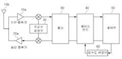
도 2 및 도 3을 참조하면, 본 발명에 따른 직접 열 확산방식시스템에서의 적응형 칩속도에 의한 전파간섭 완화 방법이 적용되는 적응형 칩속도 장치는 안테나(10b) 및 수신증폭기(10a)를 포함하는 수신부(10), 수신증폭기(20a)를 포함하는 송신부(20), 주파수 합성부(30), 필터(41), 베이스밴드(40), 제어부(50), 칩속도변경부(60)를 포함한다.2 and 3, the adaptive chip speed apparatus to which the interference interference mitigation method by the adaptive chip speed in the direct heat spreading system according to the present invention is applied, the
수신부(10)는 안테나(5)로부터 입력되는 근거리 통신(예를 들어, 지그비, 무선LAN 등)을 통한 수신신호를 수신증폭기(10a)에서 증폭한다. 이때, 수신신호는 음성 데이터, 문자 데이터, 영상 데이터 등이 포함될 수 있다.The
이때, 수신증폭기(10a)는 수신되는 신호의 출력을 증폭시키는 증폭 소재들이 사용 될 수 있다.At this time, the
주파수 합성부(30)는 송수신되는 신호의 열확산 방식에 맞게 신호를 합성하는 역할을 수행한다. 주파수 합성부(30)에서 합성된 신호는 필터(41)를 통해 원하는 신호로 분리 및 필터링한다.The
베이스밴드(40)는 칩속도를 근거로 송수신하는 신호를 확산 및 비확산시키는 역할을 수행한다.The
또한, 베이스밴드(40)는 필터(41) 등을 통해 필터링된 신호를 디지털 데이터로 변환하여 제어부(50)로 송출하도록 한다.In addition, the
제어부(50)는 입력되는 디지털 데이터에 대한 패리티 검사를 수행하여 주변의 전파잡음 수준을 파악할 수 있다. 즉, 전파잡음 수준에 대한 판단은 주변의 전파잡음이 높은 경우, 송수신되는 신호대 잡음비가 낮아져서 비트에러가 다수 발생하는데 이러한 비트오류율 발생빈도는 패리티 검사를 통하여 알 수 있게 된다. 예를 들어, 수신된 신호에 대한 패리티 검사 값이 한 프레임에서 10 이상 발생했다면 전파 잡음이 높은 것으로 판단 할 수 있다.The
제어부(50)는 주변 전파잡음의 수준을 바탕으로 칩속도를 결정하고 그 칩속도에 따라 칩속도변경부(60)를 통해 칩속도를 변경하는 신호로 베이스 밴드(60)의 송수신되는 신호의 확산시키는 칩속도를 변경한다. 예를 들어, 2.4GHz 주파수에서 열확산 방식(Direct Sequence) 중 Baker sequence 방식을 사용하는 802.11 무선LAN의 경우는 정보피트 당 11개의 확산비트를 곱하고 있고, 동일한 무선 랜의 2.4GHz 주파수를 사용하는 블루투스는 CCK 방식을 이용하여 정보비트당 8개의 확산비트를 곱하고 있다. 일반적으로 고정된 주파수 내에서 주변 전파환경을 고려하지 않고 고정된 임의의 칩속도를 사용하지만, 본 발명에 따른 제어부(50)는 패리티 체크 값에 따라(예를 들어, 패리티 검사 결과 에러율이 10이상일 때) 호핑 채널의 칩속도를 변경하도록 하게 되는 것이다.The
즉, 제어부(50)는 기설절된 사전 칩속도 집합(예를 들어, 정보비트당 8개, 16개, 32개의 확산 비트) 중에서 전파잡음 수준에 따라 현재의 칩속도를 변경하여 열 확산 방식을 통한 신호의 송수신시 확산 정도를 증가시키도록 하게 되는 것이다.That is, the
여기서, 열 확산 방식(DS; direct sequence)은 일반적으로 송신기에 정보신호 비트율보다 훨신 빠른 전송속도를 가지는 PN코드 혹은 확산부호를 사용하여 송신기 안테나로부터 발사되는 스펙트럼을 확산시키는 방식이다. 즉, 수신기는 원하는 신호만 복조하게되는데, 열 확산 방식을 통해 확산된 신호는 잡음 혹은 주변의 전파간섭에 해당하는 신호가 더욱 확산되어 원하는 신호만 복조하는데 용이하게 하도록 하는 것이다.Here, the DS (direct sequence) is a method of spreading a spectrum emitted from a transmitter antenna by using a PN code or a spreading code having a transmission rate much faster than an information signal bit rate. In other words, the receiver demodulates only a desired signal. A signal spread through a heat spreading scheme makes it easy to demodulate only a desired signal by further spreading a signal corresponding to noise or radio interference in the vicinity.
도 4는 코드 칩속도에 따른 채널 대역폭의 광대역 특성을 보여주는 도표이다. 도 4를 참조하면, 도번 10은 11Mcps 코드 칩속도의 열 확산 상태일 때의 대역폭을 보이고 있고, 도번 11은 22Mcps 코드 칩속도의 열 확산 상태일 때의 대역폭을 보이고 있다. 즉, 칩속도를 도번 10에서 도번 11과 같이 2배 올리면, 채널 대역폭은 2배로 증가하고, 동시에 수신되는 신호의 처리이득은 3dB 향상되어 간섭전력에 대한 영향은 2배로 줄어들게 된다. 이를 바탕으로 본 발명의 일실시예를 설명하도록 한다.4 is a diagram showing the broadband characteristics of the channel bandwidth according to the code chip rate. Referring to FIG. 4, FIG. 10 shows a bandwidth when the heat spread state of the 11Mcps code chip rate, and FIG. 11 shows the bandwidth when the heat spread state of the 22Mcps code chip rate. In other words, if the chip speed is doubled from 10 to 11, the channel bandwidth is doubled, and the processing gain of the received signal is increased by 3 dB, thereby reducing the influence on the interference power by 2 times. Based on this, an embodiment of the present invention will be described.
또한, 제어부(50)는 패리티 검사 결과에 따라 칩속도를 가변적으로 정하는 경우, 사전 칩속도 집합으로부터 칩속도의 변경을 단계별로 설정할 수 있다. 예를 들어, 패리티 값에 따라 전파잡음 수준을 상/중/하로 나누고, 그에 따라 사전 칩속도를 저속, 중속, 고속으로 나눌 수 있을 것이다.In addition, when the chip speed is variably determined according to the parity check result, the
따라서, 본 발명은 근거리 통신을 통해 수신되는 신호에 대한 패리티 체크 값에 따라 주변 전파잡음의 수준을 파악하고, 그에 따라 주파수 칩속도를 가변시킬 수 있게 되는 것이다.Accordingly, the present invention is to determine the level of the radio wave noise in accordance with the parity check value for the signal received through the short-range communication, it is possible to vary the frequency chip speed accordingly.
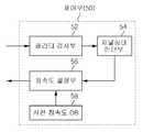
도 5는 도 3의 제어부의 내부 구성을 도시한 블록도이다.FIG. 5 is a block diagram illustrating an internal configuration of the controller of FIG. 3.
도 5를 참조하면, 본 발명에 따른 제어부(50)는 패리티 검사부(52), 채널상태 판단부(54), 칩속도 설정부(56), 사전 칩속도DB(58)를 포함할 수 있다.Referring to FIG. 5, the
패리티 검사부(52)는 상술한 신호 처리를 거쳐 입력되는 디지털 데이터에 대한 패리티 검사를 수행한다. 패리티 검사는 종래의 패리티 검사 방식이 사용될 수 있다. 즉, 패리티 검사는 주변의 주파수 혼란, 감쇠 잡음 등으로 인해 송수신된 신호에 오류가 발생하는 것을 체크하는 것을 이용하는 것이다.The
채널상태 판단부(54)는 패리티 검사부(52)에서 패리티 검사된 값을 기설정된 기준값과 비교하여 주변 전파 잡음 수준을 판단하는 역할을 수행한다.The
여기서, 기준값은 정상적인 통신가능 범위를 기준으로 가변적으로 적용할 수 있다. 예를 들어, 패리티 에러율이 0~ 10% 일 때는 정상적인 통신을 유지할 수 있다고 할 때, 패리티 에러율이 10%이상일 때는 전파 잡음으로 인해 정상적인 통신이 불가능한 경우 기준값을 10%로 지정하게 되는 것이다.Here, the reference value may be variably applied based on the normal communication range. For example, when the parity error rate is 0 to 10%, it is possible to maintain normal communication. When the parity error rate is 10% or more, the reference value is designated as 10% when normal communication is not possible due to radio noise.
상술한 바와 같이, 채널상태 판단부(54)는 패리티 검사부(52)에서 체크된 디 지털 데이터에 대한 패리티 값과 기설정된 기준값과 비교하여 전파잡음 수준에 대한 판단을 할 수 있다. 즉, 채널상태 판단부(54)는 패리티 검사 결과 값이 기준값 보다 클 경우, 수신되는 신호대 잡음비가 낮아져서 비트에러가 다수 발생하는 것으로 판단하여 주변의 전파잡음 수준이 높은 것으로 판단할 수 있다.As described above, the channel
칩속도 설정부(56)는 채널상태 판단부(54)에서 판단된 전파수준에 따라 기설정된 사전 칩속도 집합 중에서 현재 칩속도를 선택하여 상술한 칩속도변경부(60)로 변경하고자하는 현재 칩속도에 대한 제어신호를 송출할 수 있다. 즉, 칩속도 설정부(56)는 주변 전파잡음의 수준을 바탕으로 칩속도를 결정하고 그 칩속도에 따라 칩속도변경부(60)를 통해 칩속도를 변경하는 신호로 베이스밴드(60)의 칩속도를 변경하여 송수신되는 신호를 확산할 수 있도록 한다.The chip
또, 칩속도 설정부(56)는 패리티 검사부(52)로부터 검사된 패리티 값이 기준값 이상일 때, 즉, 채널상태 판단부(54)의 판단 결과가 주변 전파잡음 수준이 높을 때, 사전 칩속도DB(58)에 포함되어 있는 사전 칩속도 중에서 현재 칩속도를 상위 칩속도로 변경하도록 할 수 있다.In addition, the chip
또, 칩속도 설정부(56)는 사전 칩속도DB(58)에 저장된 사전 칩속도 집합 중에서 최저 칩속도를 현재 칩속도를 지정하고 이후 수신되는 신호에 대한 패리티 값과 기준값을 비교하여 기준값 이상일 때, 즉, 채널상태 판단부(54)의 판단 결과가 주변 전파잡음 수준이 높을 때, 상위 칩속도로 현재 칩속도를 변경하는 과정을 반복함으로써 주변 전파 잡음 수준에 맞는 칩속도를 가변적으로 적용하도록 할 수도 있다.In addition, the chip
또한, 칩속도 설정부(56)는 패리티 검사부(52)로부터 검사된 패리티 값이 기준값 이상일 때, 즉, 채널상태 판단부(54)의 판단 결과가 주변 전파잡음 수준이 높을 때, 사전 칩속도DB(58)에 포함되어 있는 사전 칩속도 중에서 현재 칩속도를 상위 칩속도로 변경하도록 할 수 있다.In addition, the chip
또, 칩속도 설정부(56)는 이전 신호에 대한 패리티 값을 기준치로 하여 수신되는 신호에 대한 패리티 값을 비교해서 기준치 이하일 때, 즉, 채널상태 판단부(54)의 판단 결과가 주변 전파잡음 수준이 이전 전파잡음 수준보다 낮아졌을 때,현재 칩속도를 하위 칩속도로 변경하도록 할 수도 있다.In addition, the chip
사전 칩속도DB(58)는 기설정된 사전 칩속도 집합을 저장한다. 예를 들어, 기설정된 사전 칩속도 집합은 사용 가능한 최저 칩속도와 최고 칩속도 사이를 하나 이상의 단계로 분류하여 지정할 수 있다(예를 들어, 정보비트당 8개, 16개, 32개의 확산비트).The advance
또한, 사전 칩속도DB(58)은 패리티 값에 따라 전파잡음 수준에 대응하는 사전 칩속도를 대응시킬 수 있다. 예를 들어, 전파잡음 수준을 상/중/하로 나누고, 그에 따라 사전 칩속도를 저속, 중속, 고속으로 나눌 수 있을 것이다.In addition, the advance
즉, 본 발명은 사전에 미리 정해진 코드 칩속도를 가변적으로 설정하여 주변의 전파환경에 대응되도록 처리이득을 높여서, 전파간섭의 면역성을 향상시키게 된다.That is, the present invention increases the processing gain so as to correspond to the surrounding radio wave environment by setting a predetermined code chip speed in advance, thereby improving the immunity of radio wave interference.
상술한 바와 같이 본 발명은 동일대역을 이용하는 타 무선기기가 존재하는 경우에 필연적으로 발생되는 전파간섭을 완화하는 목적으로서, 코드 칩속도를 주변 의 전파환경에 따라 적응적으로 변화시키는 방법을 통해 칩속도가 높아지면, 그에 따라 처리이득이 높아지므로, 타 무선기기로부터의 전파간섭에 대한 영향이 그만큼 줄어들게 되는 특성이 있다. 예를 들어, 코드 칩속도를 2배 향상시키는 처리이득은 3dB 높아지고, 그에 따라 간섭전력에 대한 영향은 2배로 줄어드는 효과가 발생한다.As described above, the present invention aims to alleviate radio interference which is inevitably generated when other wireless devices using the same band exist, and through the method of adaptively changing the code chip speed according to the surrounding radio wave environment, As the speed increases, the processing gain increases accordingly, thereby reducing the influence on radio interference from other radio devices. For example, the processing gain for doubling the code chip speed is 3dB higher, resulting in a 2x reduction in the impact on interference power.
이처럼, 본 발명은 수신되는 신호에 대한 패리티 검사 값에 따라 주변의 전파잡음 수준을 평가해서 사전에 미리 정해진 칩속도로 가변하여 동일대역을 이용하는 타 통신기기로부터 발생되는 전파간섭을 완화하도록 할 수 있다.As described above, the present invention can evaluate the radio noise level of the peripheral signal according to the parity check value for the received signal, thereby varying at a predetermined chip speed to mitigate radio interference generated from other communication devices using the same band. .
이하, 첨부된 도면을 참조하여 본 발명에 따른 실시에에 따른 적응형 칩속도에 의한 전파간섭 완화 방법에 대하여 설명한다.Hereinafter, a radio wave interference mitigation method by an adaptive chip speed according to an embodiment of the present invention will be described with reference to the accompanying drawings.
도 6은 본 발명에 따른 직접 열 확산방식시스템에서의 적응형 칩속도에 의한 전파간섭을 완화하는 방법을 도시한 순서도이다. 이하 설명에 있어서 도 1 내지 도 5와 동일한 참조 부호는 동일한 기능을 수행하는 것을 지칭한다.6 is a flowchart illustrating a method for mitigating radio wave interference by an adaptive chip speed in a direct heat diffusion system according to the present invention. In the following description, the same reference numerals as in FIGS. 1 to 5 refer to performing the same function.
도 6을 참조하면, 본 발명에 따른 적응형 주파수 칩속도에 의한 전파간섭 완화 방법은, 우선, 통신 환경에 따라 적용 가능한 칩속도에 따라 사전 칩속도 집합을 설정한다(S10). 즉, 제어부(50)는 상술한 바와 같은 사전 칩속도 집합을 사전 칩속도DB(58)내에 저장 설정하도록 한다.Referring to FIG. 6, in the interference interference mitigation method according to the adaptive frequency chip rate according to the present invention, first, a preset chip rate set is set according to a chip rate applicable according to a communication environment (S10). That is, the
이어, 제어부(50)는 사전 칩속도 집합에서 최저 칩속도를 현재 칩속도로 선택한다(S20).Subsequently, the
이때, 송신부(10)는 최저 칩속도로 확산된 동기신호 및 데이터신호를 전송하고, 수신부(10)도 최저 칩속도로 확산된 대응하는 송신부의 신호를 수신한다(S30).At this time, the
상술한 바와 같이 수신된 신호가 증폭 등의 중간 처리를 거치고, 제어부(50)는 수신된 신호의 데이터에 포함되는 비트들에 대하여 패리티 검사를 수행한다(S40).As described above, the received signal undergoes an intermediate process such as amplification and the like, and the
이후, 제어부(50)는 신호에 대한 패리티 값과 기준값을 비교하여 그 결과를 바탕으로 채널상태를 판단한다(S50).Thereafter, the
단계 S50에서 제어부(50)는 패리티 검사 결과로 전파 잡음 수준이 양호한 것으로 판단되면, 즉 신호에 대한 패리티 값의 에러검출 수가 미리 정해진 기준(기준 값)보다 작으면, 계속 최저 칩속도로 확산된 신호를 통해 통신을 수행하고, 칩속도의 적응 알고리즘을 종료한다.If it is determined in step S50 that the propagation noise level is good as a result of the parity check, that is, if the error detection number of the parity value for the signal is smaller than a predetermined reference (reference value), the signal continues to be spread at the lowest chip speed. Communicate through and terminate the chip rate adaptive algorithm.
만약, 단계 S50에서 제어부(50)는 패리티 검사 결과로 전파 잡음 수준이 높은 것으로 판단되면, 즉, 패리티 검사에서 많은 에러가 검출되면, 주변의 전파잡음 수준이 높은 것으로 판정하고, 사전 칩속도 집합에서 미리 정해진 상위 칩속도를 선택한다(S60).If, in step S50, the
즉, 제어부(50)는 선택된 상위 칩속도에 따라 칩속도변경부(60)를 통해 주파수 합성부(30)의 호핑 채널의 칩속도를 변경하도록 하게 되는 것이다.That is, the
이때, 제어부(50)는 송신부(20)를 통해 송신되는 신호와 함께 현재 선택된 칩속도 정보를 대응하는 수신기로 송부하여 동기화하도록 한다(S70).At this time, the
이와 같이, 본 발명은 송수신된 칩속도 정보를 바탕으로 확산된 신호를 전송 하고, 단계 S30 내지 단계 S60의 단계를 반복함으로써 신호에 대한 패리티 검사 결과에 따라 주변의 전파잡음 상태를 판단하여 현재 칩속도를 최대 칩속도까지 계속 반복하여 수행함으로써 양호한 통신 상태를 유지할 수 있게 된다.As described above, the present invention transmits the spread signal based on the transmitted and received chip speed information, and repeats the steps S30 to S60 to determine the propagation noise of the surroundings according to the parity check result of the signal to determine the current chip speed. By repeatedly performing the operation up to the maximum chip speed, it is possible to maintain a good communication state.
또한, 본 발명은 수신된 신호에 대한 패리티 값이 기준값 이상일 때, 즉, 채널상태 판단부(54)의 판단 결과가 주변 전파잡음 수준이 높을 때, 사전 칩속도DB(58)에 포함되어 있는 사전 칩속도 중에서 현재 칩속도를 상위 칩속도로 변경하도록 할 수 있다.In addition, the present invention, when the parity value for the received signal is greater than the reference value, that is, when the determination result of the channel
또, 본 발명은 수신된 신호에 대한 검사된 패리티 값이 기준값 이상일 때, 즉, 채널상태 판단부(54)의 판단 결과가 주변 전파잡음 수준이 높을 때, 사전 칩속도DB(58)에 포함되어 있는 사전 칩속도 중에서 현재 칩속도를 상위 칩속도로 변경하도록 할 수 있다.In addition, the present invention includes the
또, 본 발명은 이전 신호에 대한 패리티 값을 기준치로 하여 수신되는 신호에 대한 패리티 값을 비교해서 기준치 이하일 때, 즉, 채널상태 판단부(54)의 판단 결과가 주변 전파잡음 수준이 이전 전파잡음 수준보다 낮아졌을 때,현재 칩속도를 하위 칩속도로 변경하도록 할 수도 있다.In addition, the present invention compares the parity value of the received signal with the parity value of the previous signal as a reference value when the parity value is less than or equal to the reference value, that is, the result of the determination of the channel
상술한 바와 같이, 본 발명에서는 직접 열 확산 시스템에서 주변 전파잡음 환경에 따라 칩속도를 변화시켜 처리이득을 탄력적으로 운영할 수 있다.As described above, in the present invention, the processing gain can be flexibly operated by changing the chip speed according to the ambient radio noise environment in the direct heat diffusion system.
따라서, 본 발명은 직접 열 확산 통신시스템에서 주변 전파잡음 환경에 따라 적응적으로 사전에 정해진 코드 칩속도를 이산적으로 조절하여, 동일대역을 이용하는 타 통신기기로부터 발생되는 전파간섭을 완화할 수 있다.Accordingly, the present invention can mitigate radio interference generated from other communication devices using the same band by discretely adjusting a predetermined code chip speed according to the surrounding radio noise environment in a direct heat spread communication system. .
이상에서 살펴본 바와 같은 본 발명의 실시예에 대한 기술사상을 첨부도면과 함께 서술하였지만, 이는 본 발명의 가장 양호한 실시예를 예시적으로 설명한 것이지 본 발명을 한정하는 것은 아니다. 또한, 이 기술 분야에서 통상의 지식을 가진 자라면 본 발명의 기술사상을 이탈하지 않는 범위 내에서 다양한 변형 및 모방이 가능함은 명백한 사실이다.While the technical idea of the embodiment of the present invention as described above has been described with the accompanying drawings, it is intended to illustrate the best embodiment of the present invention by way of example and not to limit the present invention. In addition, it will be apparent to those skilled in the art that various modifications and variations can be made without departing from the spirit of the present invention.
도 1은 종래 기술에 따른 2.4GHz를 이용하는 지그비(IEEE 802.15.4)와 무선 랜(IEEE 802.11)의 채널번호 및 대역폭을 도시한 도표.1 is a diagram illustrating channel numbers and bandwidths of Zigbee (IEEE 802.15.4) and WLAN (IEEE 802.11) using 2.4 GHz according to the prior art.
도 2는 본 발명에 따른 적응형 칩속도 장치를 도시한 구성도.Figure 2 is a block diagram showing an adaptive chip speed device according to the present invention.
도 3은 본 발명에 따른 적응형 칩속도 장치의 내부 구성을 도시한 블록도.3 is a block diagram showing an internal configuration of an adaptive chip speed apparatus according to the present invention.
도 4는 코드 칩속도에 따른 채널 대역폭의 광대역 특성을 보여주는 도표.4 is a diagram showing broadband characteristics of channel bandwidth according to code chip speed.
도 5은 도 3의 제어부의 내부 구성을 도시한 블록도.5 is a block diagram illustrating an internal configuration of a control unit of FIG. 3.
도 6은 본 발명에 따른 직접 열 확산방식시스템에서의 적응형 칩속도에 의한 전파간섭을 완화하는 방법을 도시한 순서도.FIG. 6 is a flowchart illustrating a method for mitigating radio wave interference by an adaptive chip speed in a direct heat diffusion system according to the present invention. FIG.
* 도면의 주요부분에 대한 부호의 설명 *Explanation of symbols on the main parts of the drawings
10 : 수신부 20 : 송신부10: receiver 20: transmitter
30 : 주파수 합성부 40 : 베이스 밴드30: frequency synthesizer 40: base band
50 : 제어부 52 : 패리티 검사부50
54 : 채널상태 판단부 56 : 칩속도 설정부54: channel state determination unit 56: chip speed setting unit
58 : 사전칩속도DB 60 : 칩속도변경부58: pre-chip speed DB 60: chip speed change unit
80 : 필터80: filter
Claims (15)
Translated fromKoreanPriority Applications (1)
| Application Number | Priority Date | Filing Date | Title |
|---|---|---|---|
| KR1020070133387AKR100949793B1 (en) | 2007-12-18 | 2007-12-18 | Method and apparatus for mitigating radio wave interference by adaptive chip speed in direct heat diffusion system |
Applications Claiming Priority (1)
| Application Number | Priority Date | Filing Date | Title |
|---|---|---|---|
| KR1020070133387AKR100949793B1 (en) | 2007-12-18 | 2007-12-18 | Method and apparatus for mitigating radio wave interference by adaptive chip speed in direct heat diffusion system |
Publications (2)
| Publication Number | Publication Date |
|---|---|
| KR20090065863A KR20090065863A (en) | 2009-06-23 |
| KR100949793B1true KR100949793B1 (en) | 2010-03-30 |
Family
ID=40994061
Family Applications (1)
| Application Number | Title | Priority Date | Filing Date |
|---|---|---|---|
| KR1020070133387AActiveKR100949793B1 (en) | 2007-12-18 | 2007-12-18 | Method and apparatus for mitigating radio wave interference by adaptive chip speed in direct heat diffusion system |
Country Status (1)
| Country | Link |
|---|---|
| KR (1) | KR100949793B1 (en) |
Families Citing this family (1)
| Publication number | Priority date | Publication date | Assignee | Title |
|---|---|---|---|---|
| CN115294286B (en)* | 2022-01-12 | 2025-08-15 | 浙江理工大学 | Digital holographic object image spectrum self-adaptive extraction method for eliminating spurious spectrum |
Citations (4)
| Publication number | Priority date | Publication date | Assignee | Title |
|---|---|---|---|---|
| US20020167991A1 (en) | 2001-05-08 | 2002-11-14 | Mitsuhiro Suzuki | Transmitter, receiver, transmitting method, and receiving method |
| US20040137849A1 (en) | 2003-01-14 | 2004-07-15 | Cognio, Inc. | Mitigating Interference With Frequency Hopping Signals By Deriving Future Hop Frequencies |
| KR20060095691A (en)* | 2005-02-28 | 2006-09-01 | 삼성전기주식회사 | Zigbee and Bluetooth combined transceiver |
| EP1806872A1 (en) | 2006-01-06 | 2007-07-11 | Broadcom Corporation | Method, apparatus and system for adaptively activating or deactivating the coordination of radiocommunication activities of a Blutooth device and a WLAN device |
- 2007
- 2007-12-18KRKR1020070133387Apatent/KR100949793B1/enactiveActive
Patent Citations (4)
| Publication number | Priority date | Publication date | Assignee | Title |
|---|---|---|---|---|
| US20020167991A1 (en) | 2001-05-08 | 2002-11-14 | Mitsuhiro Suzuki | Transmitter, receiver, transmitting method, and receiving method |
| US20040137849A1 (en) | 2003-01-14 | 2004-07-15 | Cognio, Inc. | Mitigating Interference With Frequency Hopping Signals By Deriving Future Hop Frequencies |
| KR20060095691A (en)* | 2005-02-28 | 2006-09-01 | 삼성전기주식회사 | Zigbee and Bluetooth combined transceiver |
| EP1806872A1 (en) | 2006-01-06 | 2007-07-11 | Broadcom Corporation | Method, apparatus and system for adaptively activating or deactivating the coordination of radiocommunication activities of a Blutooth device and a WLAN device |
Also Published As
| Publication number | Publication date |
|---|---|
| KR20090065863A (en) | 2009-06-23 |
Similar Documents
| Publication | Publication Date | Title |
|---|---|---|
| USRE47720E1 (en) | Spectrum-adaptive networking | |
| EP1393485B1 (en) | System and method for link adaptation in communication systems | |
| US7363008B2 (en) | Spectrum sharing in the unlicensed band | |
| CN1085477C (en) | Dual-mode cellular telephone system | |
| JP5027142B2 (en) | Apparatus and method for reducing interference | |
| JP4885178B2 (en) | Ultra-wideband wireless network with interference mitigation and related methods | |
| US20070183338A1 (en) | Method and apparatus for detecting interference in a wireless communication system | |
| US20060092889A1 (en) | High density WLAN system | |
| JP2008160380A (en) | Inter-cell interference suppression method, radio base station, and user terminal | |
| CN1697438A (en) | Preamble Generator for Multiband OFDM Transceivers | |
| KR100565983B1 (en) | Interference prevention unit in wireless communication system | |
| JP2007124578A (en) | Transmission / reception bandwidth setting method, mobile terminal and base station in wireless communication system defining a plurality of signal bandwidths | |
| JP4083176B2 (en) | Ultra-wideband wireless network with frequency bin transmission level setting and related methods | |
| KR100949796B1 (en) | Radio Interference Mitigation Method and Apparatus by Adaptive Frequency Hopping Rate in Radio Noise Environment | |
| US20110151798A1 (en) | Method and apparatus for sensing multi-path spectrum of cognitive radio system and cognitive radio system thereof | |
| CN112997532B (en) | Apparatus, system and method for selecting communication protocol transmission frequency | |
| KR100949793B1 (en) | Method and apparatus for mitigating radio wave interference by adaptive chip speed in direct heat diffusion system | |
| US10863518B2 (en) | Method for handling interference in Bluetooth device having other wireless technology | |
| KR100780006B1 (en) | Printer wireless router eliminates crosstalk and interference in the ISM band | |
| US20240129784A1 (en) | Dynamic filtering system and method | |
| KR101063681B1 (en) | Wireless communication method of Bluetooth terminal | |
| JP3864231B2 (en) | COMMUNICATION SYSTEM, RECEPTION DEVICE, RECEPTION METHOD, AND PROGRAM | |
| Jha et al. | A performance comparison with modulation schemes in WiMax physical layer security aspect | |
| Tomioka et al. | A Proposal of High-Flexibility Short-Range Cognitive Radio System | |
| JP2011259487A (en) | Transmission/reception bandwidth setting method, mobile terminal, and base station in wireless communication system defining plural signal bandwidths |
Legal Events
| Date | Code | Title | Description |
|---|---|---|---|
| A201 | Request for examination | ||
| PA0109 | Patent application | Patent event code:PA01091R01D Comment text:Patent Application Patent event date:20071218 | |
| PA0201 | Request for examination | ||
| PG1501 | Laying open of application | ||
| E902 | Notification of reason for refusal | ||
| PE0902 | Notice of grounds for rejection | Comment text:Notification of reason for refusal Patent event date:20090915 Patent event code:PE09021S01D | |
| E701 | Decision to grant or registration of patent right | ||
| PE0701 | Decision of registration | Patent event code:PE07011S01D Comment text:Decision to Grant Registration Patent event date:20100303 | |
| GRNT | Written decision to grant | ||
| PR0701 | Registration of establishment | Comment text:Registration of Establishment Patent event date:20100319 Patent event code:PR07011E01D | |
| PR1002 | Payment of registration fee | Payment date:20100322 End annual number:3 Start annual number:1 | |
| PG1601 | Publication of registration | ||
| FPAY | Annual fee payment | Payment date:20130304 Year of fee payment:4 | |
| PR1001 | Payment of annual fee | Payment date:20130304 Start annual number:4 End annual number:4 | |
| FPAY | Annual fee payment | Payment date:20130730 Year of fee payment:18 | |
| PR1001 | Payment of annual fee | Payment date:20130730 Start annual number:5 End annual number:18 |