KR100949352B1 - Bone fixation - Google Patents
Bone fixationDownload PDFInfo
- Publication number
- KR100949352B1 KR100949352B1KR1020020063409AKR20020063409AKR100949352B1KR 100949352 B1KR100949352 B1KR 100949352B1KR 1020020063409 AKR1020020063409 AKR 1020020063409AKR 20020063409 AKR20020063409 AKR 20020063409AKR 100949352 B1KR100949352 B1KR 100949352B1
- Authority
- KR
- South Korea
- Prior art keywords
- bone
- screw
- hole
- plate
- connecting member
- Prior art date
- Legal status (The legal status is an assumption and is not a legal conclusion. Google has not performed a legal analysis and makes no representation as to the accuracy of the status listed.)
- Expired - Fee Related
Links
Images


Classifications
- A—HUMAN NECESSITIES
- A61—MEDICAL OR VETERINARY SCIENCE; HYGIENE
- A61B—DIAGNOSIS; SURGERY; IDENTIFICATION
- A61B17/00—Surgical instruments, devices or methods
- A61B17/56—Surgical instruments or methods for treatment of bones or joints; Devices specially adapted therefor
- A61B17/58—Surgical instruments or methods for treatment of bones or joints; Devices specially adapted therefor for osteosynthesis, e.g. bone plates, screws or setting implements
- A61B17/68—Internal fixation devices, including fasteners and spinal fixators, even if a part thereof projects from the skin
- A61B17/70—Spinal positioners or stabilisers, e.g. stabilisers comprising fluid filler in an implant
- A—HUMAN NECESSITIES
- A61—MEDICAL OR VETERINARY SCIENCE; HYGIENE
- A61B—DIAGNOSIS; SURGERY; IDENTIFICATION
- A61B17/00—Surgical instruments, devices or methods
- A61B17/56—Surgical instruments or methods for treatment of bones or joints; Devices specially adapted therefor
- A61B17/58—Surgical instruments or methods for treatment of bones or joints; Devices specially adapted therefor for osteosynthesis, e.g. bone plates, screws or setting implements
- A61B17/68—Internal fixation devices, including fasteners and spinal fixators, even if a part thereof projects from the skin
- A61B17/80—Cortical plates, i.e. bone plates; Instruments for holding or positioning cortical plates, or for compressing bones attached to cortical plates
- A61B17/8033—Cortical plates, i.e. bone plates; Instruments for holding or positioning cortical plates, or for compressing bones attached to cortical plates having indirect contact with screw heads, or having contact with screw heads maintained with the aid of additional components, e.g. nuts, wedges or head covers
- A61B17/8047—Cortical plates, i.e. bone plates; Instruments for holding or positioning cortical plates, or for compressing bones attached to cortical plates having indirect contact with screw heads, or having contact with screw heads maintained with the aid of additional components, e.g. nuts, wedges or head covers wherein the additional element surrounds the screw head in the plate hole
- A—HUMAN NECESSITIES
- A61—MEDICAL OR VETERINARY SCIENCE; HYGIENE
- A61B—DIAGNOSIS; SURGERY; IDENTIFICATION
- A61B17/00—Surgical instruments, devices or methods
- A61B17/56—Surgical instruments or methods for treatment of bones or joints; Devices specially adapted therefor
- A61B17/58—Surgical instruments or methods for treatment of bones or joints; Devices specially adapted therefor for osteosynthesis, e.g. bone plates, screws or setting implements
- A61B17/68—Internal fixation devices, including fasteners and spinal fixators, even if a part thereof projects from the skin
- A61B17/70—Spinal positioners or stabilisers, e.g. stabilisers comprising fluid filler in an implant
- A61B17/7059—Cortical plates
Landscapes
- Health & Medical Sciences (AREA)
- Orthopedic Medicine & Surgery (AREA)
- Life Sciences & Earth Sciences (AREA)
- Surgery (AREA)
- Neurology (AREA)
- Heart & Thoracic Surgery (AREA)
- Engineering & Computer Science (AREA)
- Biomedical Technology (AREA)
- Nuclear Medicine, Radiotherapy & Molecular Imaging (AREA)
- Medical Informatics (AREA)
- Molecular Biology (AREA)
- Animal Behavior & Ethology (AREA)
- General Health & Medical Sciences (AREA)
- Public Health (AREA)
- Veterinary Medicine (AREA)
- Surgical Instruments (AREA)
Abstract
Translated fromKoreanDescription
Translated fromKorean도 1은 제 1 실시예에 따른 뼈 고정장치의 사시도이다.1 is a perspective view of a bone fixing device according to the first embodiment.
도 2는 도 1에 따른 뼈 고정장치의 플레이트의 평면도이다.2 is a plan view of a plate of the bone fixation device according to FIG. 1.
도 3은 도 1에 따른 뼈 고정장치의 뼈 나사와 플레인 와셔(plain washer)의 분해사시도이다.3 is an exploded perspective view of the bone screw and plain washer of the bone fixation device according to FIG. 1.
도 4는 도 1에 따른 뼈 고정장치의 부분단면도이다.4 is a partial cross-sectional view of the bone fixing device according to FIG. 1.
도 5는 제 2 실시예에 따른 뼈 고정장치의 분해사시도이다.5 is an exploded perspective view of the bone fixing device according to the second embodiment.
도 6은 제 2 실시예에 따른 뼈 고정장치의 부분단면도이다.6 is a partial cross-sectional view of the bone fixing device according to the second embodiment.
도 7은 제 3 실시예에 따른 뼈 고정장치의 분해사시도이다.7 is an exploded perspective view of the bone fixing device according to the third embodiment.
도 8은 제 3 실시예에 따른 뼈 고정장치의 부분단면도이다.8 is a partial cross-sectional view of the bone fixing device according to the third embodiment.
도 9는 제 4 실시예에 따른 뼈 고정장치의 분해사시도이다.9 is an exploded perspective view of the bone fixing device according to the fourth embodiment.
도 10은 제 4 실시예에 따른 뼈 고정장치의 부분단면도이다.10 is a partial cross-sectional view of the bone fixing device according to the fourth embodiment.
도 11은 상기 실시예들의 뼈 나사의 변형예의 사시도이다.11 is a perspective view of a modification of the bone screw of the above embodiments.
도 12는 상기 실시예들의 뼈 고정장치의 플레이트의 변형된 형태를 나타내는 도면이다.12 is a view showing a modified form of the plate of the bone fixing device of the above embodiments.
본 발명은 뼈 고정장치, 특히 경추를 안정화시키는 장치에 관한 것이다.The present invention relates to a bone fixation device, in particular a device for stabilizing the cervical spine.
특히 경추를 안정화시키기 위한 장치는 공지된 것으로서, M 나사산을 구비하는 적어도 하나의 보어를 가지는 플레이트, 및 이 플레이트 내에 나사체결되기 위한 뼈 나사를 포함한다. 뼈 나사는 뼈에 나사결합하는 뼈 나사산을 가진 나사산 부분과, M 수나사산을 가지는 인접한 나사산 부분을 가진다. 시술시, 뼈 나사는 보어를 통해 안내되어 뼈에 나사결합된다. 그런 다음, 제2의 나사산 부분이 플레이트 내에 나사결합된다. 나사산들의 피치(pitch)는 서로 다르기 때문에 뼈 나사가 뼈 나사 시이트(seat)로부터 느슨해질 위험이 있다.In particular, the device for stabilizing the cervical spine is known and comprises a plate having at least one bore with M threads, and bone screws for screwing into the plate. The bone screw has a threaded portion with bone threads that screw into the bone and an adjacent threaded portion with M male threads. During the procedure, the bone screw is guided through the bore and screwed to the bone. The second threaded portion is then screwed into the plate. Since the pitch of the threads is different, there is a risk that the bone screw will loosen from the bone screw seat.
WO 96/05778호로부터 경추 안정화 시스템이 공지되었다. 이 시스템은 적어도 한 개의 구멍을 가지는 플레이트, 뼈 나사산 부분과 그에 인접한 M-나사산 부분을 구비하는 뼈나사, 및 뼈 나사산 부분과 M-나사산 부분 사이에 제공된 방사상 돌출부, 및 상기 M 나사산 부분과 협동하는 너트를 구비한다. 이 공지의 장치는 우선 뼈 나사를 뼈에 나사결합시킨 다음, 구멍을 가진 플레이트를 이것이 상기 방사상 돌출부에 안착할 때까지 M 나사산 부분 위로 안내하고, 그런 다음, 너트를 상기 구멍에 삽입하고 M-나사산 부분에 나사결합하여 고정시킨다. 상기 구멍은 긴 구멍으로 구성할 수 있다.Cervical stabilization systems are known from WO 96/05778. The system cooperates with a plate having at least one hole, a bone screw having a bone thread portion and an M-thread portion adjacent thereto, and a radial protrusion provided between the bone thread portion and the M-thread portion, and the M thread portion. With a nut. The known device first screws the bone screw into the bone, then guides the plate with the hole over the M threaded portion until it rests on the radial protrusion, and then inserts a nut into the hole and the M-threaded thread. Screw it to the part and fix it. The hole may be configured as a long hole.
WO 00/18312호로부터 척추 안정화 장치가 공지되었다. 이 장치는 적어도 한개의 구멍을 가지는 플레이트, 뼈 나사산 부분과 M 나사산 부분을 구비하는 뼈 나사, 이들 나사산 부분의 사이에 제공된 돌출부, 및 상기 구멍의 가장자리의 상면에 얹히는 플레인 와셔(plain washer), 및 시임(shim)에 인접할 때까지 뼈 나사의 M 나사산 부분의 위에 나사결합되는 너트를 구비한다. 상기 플레인 와셔는 측면 구멍을 가지고 있으므로 뼈 나사는 다양한 각도를 취할 수 있다.Spinal stabilization devices are known from WO 00/18312. The device comprises a plate having at least one hole, a bone screw having a bone thread portion and an M thread portion, a protrusion provided between these thread portions, and a plain washer mounted on the top surface of the edge of the hole, And a nut screwed onto the M threaded portion of the bone screw until adjacent to the shim. Since the plain washer has side holes, the bone screw can take various angles.
상기 공지의 시스템들은 각각 특정한 용도에 적합하다. 예를 들어, 첫번째 언급된 장치에서는, 항상 플레이트를 먼저 배치한 다음 나사를 플레이트에 결합해야 한다. 한편, WO 96/05778호로부터 공지 장치에서는 먼저 나사를 결합한 다음 플레이트를 상측에 배치해 주어야 한다. 또한, 이 장치에서는 나사의 각도를 변경할 수 없다. WO 00/18312호로부터 공지된 장치는 뼈 나사의 각도를 변경할 수 있지만, 플레이트의 길이 방향으로의 조정이 제한된 범위 내에서만 가능하다. 또한, 이 장치는 비교적 복잡한 구성을 가진다.Each of these known systems is suitable for a particular application. For example, in the first mentioned device, the plate must always be placed first and then the screws are joined to the plate. On the other hand, in the known device from WO 96/05778, the screw must first be engaged and then the plate must be placed on the upper side. In addition, the angle of the screw cannot be changed in this device. The device known from WO 00/18312 can change the angle of the bone screw, but only within the limited range of adjustment of the plate in the longitudinal direction. In addition, the device has a relatively complicated configuration.
본 발명의 목적은 공지의 장치들에 비해 조절기능과 적용범위가 향상된 뼈 고정장치, 특히, 경추를 안정화 시키기 위한 장치를 제공하는데 있다.It is an object of the present invention to provide a device for stabilizing bone, in particular, a device for stabilizing the cervical spine, with improved control and coverage compared to known devices.
이 목적은 특허청구범위의 제 1 항에 따른 뼈 고정장치에 의해 달성된다. 본 발명의 추가 실시형태는 특허청구범위의 종속 청구항들에 기재되어 있다.This object is achieved by a bone fixation device according to claim 1. Further embodiments of the invention are described in the dependent claims of the claims.
본 발명은 적용 범위를 상당히 확장시키는 모듈식 시스템의 특수한 장점을 가진다. 본 발명에 따른 장치는 경추의 안정화 뿐 아니라 골절된 뼈(예, 관상골)를 고정하기 위한 뼈 고정장치로서도 사용할 수 있다. 또한, 본 발명은 의사가 수술실에서, 나사를 먼저 끼운 다음 그 위에 플레이트를 배치하고 고정해야 할지, 아니면 플레이트를 먼저 배치하고 그 플레이트의 구멍을 통해 뼈 나사를 결합해야 할지에 관하여, 각각의 상황에 맞는 결정을 내릴 수 있게 한다. 또한, 본 발명은 단축 나사 및 다축 나사를 하나의 플레이트와 함께 사용할 수 있게 하며, 심지어는 양 타입의 나사들을 서로 인접하여 사용할 수 있게 한다. 그리하여, 플레이트에 대한 나사의 각도 조절과, 나사의 길이방향 거리의 조정을 위한 나사의 위치 결정은 각각의 나사에 대해 독립적으로 실행할 수 있다.The present invention has the particular advantage of modular systems which significantly extend the scope of application. The device according to the invention can be used not only for stabilizing the cervical spine but also as a bone fixation device for fixing fractured bones (eg, coronal bone). In addition, the present invention relates to each situation in the operating room, in which case the surgeon should first insert the screws and then place and secure the plate thereon or place the plate first and engage the bone screw through the hole in the plate. Make the right decision. In addition, the present invention makes it possible to use a single screw and a multiaxial screw together with one plate, and even to use both types of screws adjacent to each other. Thus, the adjustment of the screw angle to the plate and the positioning of the screw for the adjustment of the longitudinal distance of the screw can be carried out independently for each screw.
본 발명의 추가 특징과 장점들은 도면을 참조한 하기 실시예의 설명으로부터 드러난다.Further features and advantages of the invention emerge from the description of the following examples with reference to the drawings.
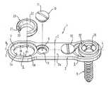
도 1 내지 도 4에서 볼 수 있는 바와 같이, 뼈 고정장치(1)는 모서리가 둥근 대체로 직사각형인 플레이트(2)를 가진다. 보다 상세한 설명을 위해, 직사각형의 길이 방향으로 연장하는 플레이트의 중심선을 D로 나타내고, 그 중심선에 수직으로 교차하는 플레이트의 중심선을 C로 나타낸다. 상기 플레이트는 각각 제 1 단부(3)와 제 2 단부(4), 및 뼈 나사를 수용하기 위해 이들 각 단부에 인접하여 제공되는 구멍(5)을 구비한다. 각각의 구멍(5)은 중심선(D)에 대해 수직 방향인 제 1 직경(d1)을 가지는 제 1 영역(5a)과 중심선(D)에 대해 수직 방향인 제 2 직경(d2)을 가지는 제 2 영역(5b)을 가지며, 상기 제 2 직경(d2)은 제 1 직경(d1) 보다 크다. 길이 방향, 다시 말해 중심선(D) 방향으로의 구멍(5)의 전체 직경은 상기 제 2 직경(d2) 보다 크다. 영역(5a, 5b)들은, 예를 들어, 영역(5a)의 직경에 대응하는 작은 직경과 그리고 영역(5b)의 직경(d2)에 대응하는 큰 직경을 가지는 추가의 보어를 가지는 기다란 구멍으로 형성되어 있다. 영역(5a, 5b)들은 영역(5b)이 플레이트의 각 단부(3 또는 4)로부터 먼 쪽인 중심선(C)쪽에 위치하도록 플레이트 상에 배치되어 있다. 사용 상태시 뼈 나사(6)의 생크(shank)로부터 먼쪽으로 향하는 플레이트(2) 상부측(2a)의 각각의 구멍(5)에는 후술되는 연결 부재를 수용하기 위한 오목부(7)가 구비되어 있다.As can be seen in FIGS. 1 to 4, the bone fixation device 1 has a generally
플레이트(2)의 양 구멍(5)의 영역(5b)의 인접부에는 나사보어(8)가 구비되어 있다. 이 나사보어는 서로 마주보고 위치하고, 예를 들면 슬릿나사로서 구성되는 고정구(10, 11)로서 헤드(11)를 구비하는 고정부재인 고정나사(10)가 나사결합하기 위한 오목부(9)를 구비하고 있다. 나사보어(8)는 구멍(5)의 영역(5b)으로부터 일정 간격만큼 이격된 위치에 제공되며, 오목부(9)와 고정나사(10)의 헤드(11)는 나사결합된 상태에서 헤드(11)가 구멍(5)의 영역(5b) 내의 오목부(7)의 영역 내로 약간 돌출함으로써 오목부(7)의 단면을 제한하는 치수로 되어 있다.A
특히 도 1 , 도 3 및 도 4 에서 볼 수 있는 바와 같이, 뼈 나사를 플레이트(2)에 연결하기 위해, 뼈 고정장치는 슬리브 형상으로 형성된 지지부재 또는 성형된 부품 형태의 연결 부재를 갖는다(이하, 플레인 와셔(plain washer)(20)라고 부른다). 플레인 와셔(20)는 중공의 원통형 부분(21)을 가지고, 그 길이는 구멍(5)의 영역의 플레이트의 두께보다 약간 길다. 플레이트(2)의 상부측(2a)에 삽입된 상태에서 플레인 와셔(20)는 중공의 부분 구형상 부분(22)을 가지고 있고, 그 부분(22)의 외경은 오목부(7)의 중심선(D) 방향의 직경보다는 작으나, 제 2 영역(5b)의 직경(d2) 보다는 크다. 따라서 삽입된 상태에서, 플레인 와셔(20)의 부분(22)은 오목부(7)의 가장자리의 상면에 놓인다. 중공의 부분 구형상 부분(22)의 내면의 구면 반경은 뼈나사(6)의 구형상의 헤드(6a)의 구면 반경에 일치한다. 플레인 와셔(20)의 부분 구형상 부분(22)으로부터 먼 쪽에는 링형상의 돌출부(23)가 구비되어 있다. 이 돌출부의 외경은 구멍(5)의 제 1 영역(5a)의 직경(d1) 보다 크고, 구멍(5)의 제 2 영역(5b)의 직경(d2) 보다 작다. 따라서, 플레인 와셔(20)는 구멍(5)의 대직경(d2)의 제 2 영역(5b)을 통해 구멍(5) 내로 삽입된 후, 오목부(7) 내에서 플레이트의 길이 방향을 따라 영역(5a) 내로 변위되어 탈락이 방지될 수 있는 치수로 되어있다. 오목부(7)는 플레인 와셔를 위한 가이드를 형성한다.As can be seen in particular in FIGS. 1, 3 and 4, in order to connect the bone screws to the
제 1 실시예의 뼈 고정장치(1)는 뼈 나사(6)를 더 포함한다. 본 실시예에서 그 뼈 나사(6)는 뼈에 나사결합되는 뼈 나사산을 가진 생크(15)와 부분 구형상으로 성형되어 생크에 단단히 연결된 헤드(6a)를 가지는 단일체로 구성되어 있고, 그 헤드(6a)의 상측면에는 나사 조임 공구가 결합되는 수단(16)(예, 다수의 슬릿)이 구비되어 있다.The bone fixation device 1 of the first embodiment further comprises a
시술시, 우선 플레인 와셔(20)를 구멍(5)의 영역(5b)을 통해 진입시키면 중공의 부분 구형상 부분(22)이 플레이트의 상부측(2a)에 위치한다. 다음, 플레인 와셔를 영역(5a)의 방향으로 밀어주면 중공의 부분 구형상 부분(22)의 하면이 오목부(7)의 상면에 놓인다. 소직경(d1)을 가진 영역(5a)에서 플레인 와셔(20)는 대직경인 중공의 부분 구형상 부분(22)과 돌출부(23)에 의해 탈락되지 않고 유지된다. 다음, 고정 나사(9)를 보어(8)에 나사결합한다. 도 1, 도 2 및 도 4에서 볼 수 있는 바와 같이, 고정 나사(9)의 헤드(11)의 가장자리는 구멍(5)의 오목부(7)의 영역 내로 조금 돌출함으로써 영역(5b)의 오목부(7)의 직경을 제한하고, 그 결과 삽입된 플레인 와셔(20)를 탈락하지 않도록 고정해 준다. 그러나, 플레인 와셔(20)는 여전히 구멍(5)에서 길이 방향으로 변위될 수 있으므로 원하는 정확한 위치까지 밀어줄 수 있다. 다음, 뼈 나사산을 가진 나사산 생크(15)를 가진 뼈 나사(6)를 플레인 와셔를 통해 진입시켜 뼈에 나사결합한다.During the procedure, the
시술 중, 의사는 플레인 와셔(20)가 삽입되어 고정나사(10)에 의해 탈락되지 않도록 고정된 상태의 일체형 플레이트를 사용하여, 치료 대상의 뼈 부분에 대해 플레이트를 밀착시킨 다음, 뼈 나사(6)를 나사체결해 넣는다. 플레인 와셔는 변위가 가능하므로 나사체결 전에 나사체결 위치의 조정이 가능하다.During the procedure, the surgeon uses the integral plate with the
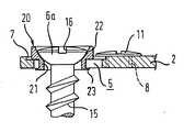
도 5 및 도 6에 도시된 실시예에서 플레이트(2)에 대한 것은 도 1 내지 도 4에 도시된 실시예와 동일하지만 뼈 나사(60)는 다르다. 이 뼈 나사(60)는 뼈 나사산을 가지는 제 1 나사산 생크 부분(61)과 M-나사산을 가지는 제 2 나사산 생크 부분(62)을 가진다. 제 2 나사산 생크 부분(62)의 직경은 플레인 와셔(20)의 내부 직경보다 작다. 따라서, 제 2 나사산 생크 부분(62)은 슬리브(sleeve) 상으로 구성된 플레인 와셔(20)를 통해 안내될 수 있다. 뼈 나사의 첨단부의 반대쪽 단부에는 뼈 나사를 뼈에 나사결합하기 위한 나사조임 공구가 맞물리는 육각형의 오목부(도시되지 않음)가 구비되어 있다.In the embodiment shown in FIGS. 5 and 6, the same for the
본 실시예에서, 나사(60)의 헤드는 별체의 너트(63)에 의해 형성된다. 이 너트는 플레인 와셔(20)의 중공의 부분 구형 부분(22)의 반경에 상응하는 반경을 가진 부분 구형으로 형성된 것이다. 이 너트(63)는 부분 구형 부분으로부터 먼쪽의 상부측에 나사조임 공구가 맞물리는 수단(64)(예, 슬릿)을 구비한다.In this embodiment, the head of the
시술시, 우선 플레인 와셔(들)(20)을 플레이트(2)의 구멍(5) 내에 삽입하고, 고정나사(10)로 고정하여 탈락을 방지한다. 시술 중, 우선 플레이트(2)를 치료 대상의 뼈 부분에 밀착시킨 상태에서 뼈에 대한 정확한 나사결합 위치를 표시한다. 다음, 뼈 나사(60)를 나사삽입하고, 뼈로부터 돌출한 제2의 나사산 부분(62) 상에 플레이트(2)의 구멍(5)을 위치시킨다. 다음, 너트(63)가 플레인 와셔(20)의 중공의 부분 구형 부분(22) 내에 안착될 때까지 너트(63)를 제 2 나사산 부분에 나사결합한다. 여기서 플레인 와셔(20)의 구형 부분과 너트(63)의 구형 부분으로 인해 뼈 나사의 각도를 소정의 각도 범위 내서 조절할 수 있다.At the time of the procedure, the plain washer (s) 20 is first inserted into the
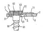
도 7 및 도 8에 나타낸 실시예는 도 5 및 도 6에 나타낸 실시예와 달리 플레인 와셔(20)의 중공의 부분 구형 부분(22)의 외단부에 소정 치수만큼 내측으로 돌출하는 가장자리부(24)를 구비한다. 이 가장자리부는 삽입된 너트(63)의 상부측을 둘러싸서 고정함으로써 너트(63)의 탈락을 방지한다.7 and 8 differ from the embodiment shown in FIGS. 5 and 6 by means of an
본 실시예의 시술시, 플레인 와셔(20)는 너트(63)가 이미 삽입된 상태로 사전 조립되고, 전술한 실시예들과 마찬가지로 먼저 플레이트(2) 내에 삽입되고, 고정나사(10)로 고정하여 탈락이 방지된다. 추가의 시술은 도 5 및 도 6 에 나타낸 실시예와 동일하게 이루어진다. 본 실시예는 너트(63)가 포획되어 있으므로 시술 중에 의사가 너트를 떨어뜨릴 가능성이 없다는 장점이 있다.During the procedure of the present embodiment, the
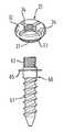
도 9 및 도 10에 나타낸 실시예에서, 플레이트와 뼈 나사 사이의 연결 부재는, 플레인 와셔 대신, 뼈 나사(60)의 제 2 나사산 생크 부분(62)에 나사결합하기 위한 너트(30)로서 구성된다. 이 너트(30)는 전술한 실시예들의 플레인 와셔의 중공의 원통형 중심부(21)와 치수가 동일하고, 내부에 암나사산이 구비되어 있는 제 1 영역(31)을 가지고 있다. 상기 중심부(21)의 일 단부에 인접하는 너트(30)는 그 외경이 플레인 와셔(20)와 마찬가지로 오목부(7)의 직경 보다는 약간 작으나, 구멍(5)의 제 2 영역(5b)의 직경(d2) 보다는 크다. 상기 중심부(31)의 다른 단부에는 플레인 와셔(20)와 마찬가지로 링 형상의 돌출부(33)가 제공되어 있다. 또 너트의 상부측에는 나사 조임 공구가 맞물리기 위한 수단(34)(예, 슬릿)이 구비되어 있다.In the embodiment shown in FIGS. 9 and 10, the connecting member between the plate and the bone screw is configured as a
본 실시예에서 뼈 나사(60)는 쇼울더(65)를 구비한다. 이 쇼울더는 뼈 나사산 생크 부분(61)과 M-나사산을 가진 나사산 생크 부분(62) 사이에 배치된다. 이 쇼울더는, 예를 들면, 링 형상의 돌출부로서 형성되고, 특히 도 10에 도시된 바와 같이, 나사결합 중에 스토퍼의 역할을 한다.The
시술시, 뼈 나사(들)(60)을 사전에 정해진 위치에 나사결합하고, 플레이트의 구멍(5)을 나사산 부분(62) 상에 위치시킨 다음 너트(30)를 체결한다.During the procedure, the bone screw (s) 60 are screwed into a predetermined position, the
도 11에 나타낸 실시예에서 뼈 나사의 뼈 나사산 생크 부분은 중공체로서 구성되어 있고, 2 개의 마주보는 길이 방향 슬릿(66)을 가진다. 또한, 생크의 내부에는 도시를 생략한 확장부재가 제공된다. 이 확장부재는 종방향 슬릿(66)에 의해 형성된 생크 부분을 이격시키도록 작용할 수 있다. 뼈 나사산 생크 부분이 나사결합되면 확장 효과가 발생하고, 그 결과 결합력이 향상될 수 있다.In the embodiment shown in FIG. 11 the bone thread shank portion of the bone screw is configured as a hollow body and has two opposing
도 12에 도시된 실시예의 플레이트(200)는 특히 경추의 안정화에 사용하기 위해 구성된 것으로서, 양 단부(3, 4)에 각각 2개의 구멍(5)을 가지고 있고, 이들 인접한 2개의 구멍(5)은 하나의 고정나사(10)를 공유한다. 이러한 목적을 위해, 고정나사(10)를 위한 보어(8)의 축선은 중앙 종축선(D) 상에 배치되고, 나사 헤드(11)의 치수와 보어의 위치는 나사결합된 상태에서 나사 헤드(11)가 인접한 구멍(5)들의 양 오목부(7) 모두에 맞물리도록 선택된다. 또한, 플레이트(200)는 중간부가 잘록하게 구성된다.The
상기 실시예들은 하나의 플레이트 상에 임의의 방법으로 결합될 수 있고, 또는 목적에 따라 나사들을 다양한 실시예에 대해 사용할 수 있으므로 범용성이 큰 모듈형 시스템을 얻을 수 있다.The above embodiments can be combined in any way on one plate, or the screws can be used for various embodiments depending on the purpose, resulting in a highly versatile modular system.
고정나사(10) 대신 상이한 고정부재를 제공할 수 있다. 예를 들면, 플레이트에 부착되는 스프링 부재는 플레인 와셔(20)나 너트(30)의 삽입시에는 굴곡변형되어 정위치로부터 벗어난 후, 원위치로 복귀하여 구멍의 단면을 제한한다.Different fixing members may be provided instead of the fixing
"플레이트"이란 용어는, 예를 들어, 완전한 평평체가 아니고, 굴곡되거나 다른 여러가지 방법으로 휘어진 표면을 가지는 부재들도 포함하는 것으로 해석되어야 한다.The term " plate " should be construed to include, for example, members which are not perfectly flat, but which have curved or curved surfaces.
본 발명에 따른 뼈 고정장치는 경추를 안정화시키는데 적용될 수 있을 뿐만 아니라, 골절된 뼈(예, 관상골)의 외부치료에 적합할 수도 있다.The bone fixation device according to the invention can be applied not only to stabilizing the cervical spine but also suitable for external treatment of fractured bones (eg coronal bone).
Claims (16)
Translated fromKoreanApplications Claiming Priority (2)
| Application Number | Priority Date | Filing Date | Title |
|---|---|---|---|
| DE10152094ADE10152094C2 (en) | 2001-10-23 | 2001-10-23 | Bone fixation device |
| DE10152094.8 | 2001-10-23 |
Publications (2)
| Publication Number | Publication Date |
|---|---|
| KR20030033932A KR20030033932A (en) | 2003-05-01 |
| KR100949352B1true KR100949352B1 (en) | 2010-03-26 |
Family
ID=7703309
Family Applications (1)
| Application Number | Title | Priority Date | Filing Date |
|---|---|---|---|
| KR1020020063409AExpired - Fee RelatedKR100949352B1 (en) | 2001-10-23 | 2002-10-17 | Bone fixation |
Country Status (5)
| Country | Link |
|---|---|
| US (2) | US7771458B2 (en) |
| EP (1) | EP1306057B1 (en) |
| JP (1) | JP4297675B2 (en) |
| KR (1) | KR100949352B1 (en) |
| DE (2) | DE10152094C2 (en) |
Cited By (3)
| Publication number | Priority date | Publication date | Assignee | Title |
|---|---|---|---|---|
| KR101178488B1 (en) | 2011-03-24 | 2012-09-06 | 주식회사 솔고 바이오메디칼 | Apparatus for bone fixation |
| KR101226221B1 (en)* | 2011-08-18 | 2013-01-28 | 김일환 | Apparatus for bone fixation |
| KR101981114B1 (en) | 2018-12-07 | 2019-05-22 | 의료법인 명지의료재단 | Compression locking type bone fixation device |
Families Citing this family (137)
| Publication number | Priority date | Publication date | Assignee | Title |
|---|---|---|---|---|
| US20060041260A1 (en)* | 2000-02-01 | 2006-02-23 | Orbay Jorge L | Fixation system with plate having holes with divergent axes and multidirectional fixators for use therethrough |
| US6767351B2 (en)* | 2000-02-01 | 2004-07-27 | Hand Innovations, Inc. | Fixation system with multidirectional stabilization pegs |
| US6893444B2 (en)* | 2000-02-01 | 2005-05-17 | Hand Innovations, Llc | Bone fracture fixation systems with both multidirectional and unidirectional stabilization pegs |
| US6706046B2 (en)* | 2000-02-01 | 2004-03-16 | Hand Innovations, Inc. | Intramedullary fixation device for metaphyseal long bone fractures and methods of using the same |
| US20040153073A1 (en)* | 2000-02-01 | 2004-08-05 | Hand Innovations, Inc. | Orthopedic fixation system including plate element with threaded holes having divergent axes |
| US7857838B2 (en) | 2003-03-27 | 2010-12-28 | Depuy Products, Inc. | Anatomical distal radius fracture fixation plate |
| US7695502B2 (en) | 2000-02-01 | 2010-04-13 | Depuy Products, Inc. | Bone stabilization system including plate having fixed-angle holes together with unidirectional locking screws and surgeon-directed locking screws |
| US7766947B2 (en) | 2001-10-31 | 2010-08-03 | Ortho Development Corporation | Cervical plate for stabilizing the human spine |
| US7070599B2 (en) | 2002-07-24 | 2006-07-04 | Paul Kamaljit S | Bone support assembly |
| US6755833B1 (en) | 2001-12-14 | 2004-06-29 | Kamaljit S. Paul | Bone support assembly |
| CA2471843C (en) | 2001-12-24 | 2011-04-12 | Synthes (U.S.A.) | Device for osteosynthesis |
| US7077843B2 (en) | 2002-06-24 | 2006-07-18 | Lanx, Llc | Cervical plate |
| US7175623B2 (en) | 2002-06-24 | 2007-02-13 | Lanx, Llc | Cervical plate with backout protection |
| US20040111090A1 (en)* | 2002-10-03 | 2004-06-10 | The University Of North Carolina At Chapel Hill | Modification of percutaneous intrafocal plate system |
| US7476228B2 (en)* | 2002-10-11 | 2009-01-13 | Abdou M Samy | Distraction screw for skeletal surgery and method of use |
| US7524325B2 (en)* | 2002-11-04 | 2009-04-28 | Farid Bruce Khalili | Fastener retention system |
| US20050187551A1 (en)* | 2002-12-02 | 2005-08-25 | Orbay Jorge L. | Bone plate system with bone screws fixed by secondary compression |
| US7780664B2 (en)* | 2002-12-10 | 2010-08-24 | Depuy Products, Inc. | Endosteal nail |
| US7175624B2 (en)* | 2002-12-31 | 2007-02-13 | Depuy Spine, Inc. | Bone plate and screw system allowing bi-directional assembly |
| US7914561B2 (en) | 2002-12-31 | 2011-03-29 | Depuy Spine, Inc. | Resilient bone plate and screw system allowing bi-directional assembly |
| WO2004062482A2 (en)* | 2003-01-10 | 2004-07-29 | Abdou Samy M | Plating system for bone fixation and subsidence and method of implantation |
| US7341591B2 (en)* | 2003-01-30 | 2008-03-11 | Depuy Spine, Inc. | Anterior buttress staple |
| US8172885B2 (en) | 2003-02-05 | 2012-05-08 | Pioneer Surgical Technology, Inc. | Bone plate system |
| DE602004001398T2 (en)* | 2003-03-20 | 2007-06-14 | Stryker Trauma S.A. | BONE CONNECTION DEVICE |
| US20040193155A1 (en)* | 2003-03-27 | 2004-09-30 | Hand Innovations, Inc. | Fracture fixation plate with particular plate hole and fastener engagement and methods of using the same |
| DE502004010444D1 (en) | 2003-04-03 | 2010-01-14 | Medartis Ag | RECORDING FOR A BLOCKING ELEMENT AND BLOCKING ELEMENT |
| DE10317871B3 (en)* | 2003-04-17 | 2004-11-11 | Stryker Leibinger Gmbh & Co. Kg | Osteosynthesis device |
| US7291152B2 (en)* | 2003-04-18 | 2007-11-06 | Abdou M Samy | Bone fixation system and method of implantation |
| US7169150B2 (en)* | 2003-04-25 | 2007-01-30 | Warsaw Orthopedic, Inc. | Non-metallic orthopedic plate |
| US7309340B2 (en) | 2003-06-20 | 2007-12-18 | Medicinelodge, Inc. | Method and apparatus for bone plating |
| US7306605B2 (en) | 2003-10-02 | 2007-12-11 | Zimmer Spine, Inc. | Anterior cervical plate |
| CA2548469A1 (en)* | 2003-12-01 | 2005-06-16 | Smith & Nephew, Inc. | Humeral nail with insert for fixing a screw |
| US7635366B2 (en)* | 2003-12-29 | 2009-12-22 | Abdou M Samy | Plating system for bone fixation and method of implantation |
| US7740649B2 (en) | 2004-02-26 | 2010-06-22 | Pioneer Surgical Technology, Inc. | Bone plate system and methods |
| US8900277B2 (en) | 2004-02-26 | 2014-12-02 | Pioneer Surgical Technology, Inc. | Bone plate system |
| US7311712B2 (en)* | 2004-02-26 | 2007-12-25 | Aesculap Implant Systems, Inc. | Polyaxial locking screw plate assembly |
| US7942913B2 (en)* | 2004-04-08 | 2011-05-17 | Ebi, Llc | Bone fixation device |
| US7578834B2 (en)* | 2004-05-03 | 2009-08-25 | Abdou M S | Devices and methods for the preservation of spinal prosthesis function |
| EP1758511A4 (en)* | 2004-06-14 | 2008-12-03 | M S Abdou | Occipital fixation system and method of use |
| US7641690B2 (en)* | 2004-08-23 | 2010-01-05 | Abdou M Samy | Bone fixation and fusion device |
| WO2006041963A2 (en)* | 2004-10-05 | 2006-04-20 | Abdou M S | Devices and methods for inter-vertebral orthopedic device placement |
| DE102004050040A1 (en) | 2004-10-08 | 2006-04-20 | Aesculap Ag & Co. Kg | bone screw |
| US9615866B1 (en) | 2004-10-18 | 2017-04-11 | Nuvasive, Inc. | Surgical fixation system and related methods |
| WO2006047555A2 (en)* | 2004-10-25 | 2006-05-04 | Alphaspine, Inc. | Bone fixation systems and methods |
| WO2006047711A2 (en)* | 2004-10-25 | 2006-05-04 | Alphaspine, Inc. | Pedicle screw systems and methods |
| US7604655B2 (en)* | 2004-10-25 | 2009-10-20 | X-Spine Systems, Inc. | Bone fixation system and method for using the same |
| US20060106387A1 (en)* | 2004-11-16 | 2006-05-18 | Depuy Spine, Inc. | Spinal plate system and method of use |
| WO2006058221A2 (en) | 2004-11-24 | 2006-06-01 | Abdou Samy M | Devices and methods for inter-vertebral orthopedic device placement |
| US7935137B2 (en) | 2004-12-08 | 2011-05-03 | Depuy Spine, Inc. | Locking bone screw and spinal plate system |
| US7410488B2 (en) | 2005-02-18 | 2008-08-12 | Smith & Nephew, Inc. | Hindfoot nail |
| AU2006214001B2 (en) | 2005-02-18 | 2011-05-26 | Samy Abdou | Devices and methods for dynamic fixation of skeletal structure |
| WO2006096756A2 (en)* | 2005-03-07 | 2006-09-14 | Abdou M Samy | Occipital fixation system |
| US7931681B2 (en)* | 2005-04-14 | 2011-04-26 | Warsaw Orthopedic, Inc. | Anti-backout mechanism for an implant fastener |
| WO2006138500A2 (en)* | 2005-06-16 | 2006-12-28 | Robinson James C | Bone screw retaining system |
| US7717943B2 (en) | 2005-07-29 | 2010-05-18 | X-Spine Systems, Inc. | Capless multiaxial screw and spinal fixation assembly and method |
| US20070093822A1 (en)* | 2005-09-28 | 2007-04-26 | Christof Dutoit | Apparatus and methods for vertebral augmentation using linked expandable bodies |
| US7905909B2 (en)* | 2005-09-19 | 2011-03-15 | Depuy Products, Inc. | Bone stabilization system including multi-directional threaded fixation element |
| US20070083202A1 (en)* | 2005-09-20 | 2007-04-12 | Donald Eli Running | Intramedullary bone plate with sheath |
| WO2007041648A2 (en)* | 2005-10-03 | 2007-04-12 | Abdou Samy M | Devices and methods for inter-vertebral orthopedic device placement |
| WO2007041702A2 (en)* | 2005-10-04 | 2007-04-12 | Alphaspine, Inc. | Pedicle screw system with provisional locking aspects |
| US8870920B2 (en) | 2005-10-07 | 2014-10-28 | M. Samy Abdou | Devices and methods for inter-vertebral orthopedic device placement |
| US8097025B2 (en) | 2005-10-25 | 2012-01-17 | X-Spine Systems, Inc. | Pedicle screw system configured to receive a straight or curved rod |
| AU2005338325A1 (en) | 2005-11-16 | 2007-05-24 | Synthes Gmbh | A through hole for bone fixation device |
| US20070162132A1 (en) | 2005-12-23 | 2007-07-12 | Dominique Messerli | Flexible elongated chain implant and method of supporting body tissue with same |
| US8029551B2 (en)* | 2006-01-10 | 2011-10-04 | Running Donald E | Fracture fixation plate with cover sheath |
| US20120029576A1 (en)* | 2006-05-26 | 2012-02-02 | Mark Richard Cunliffe | Bone Fixation Device |
| US10085780B2 (en) | 2006-05-26 | 2018-10-02 | Mark Richard Cunliffe | Bone fixation device |
| US8303630B2 (en)* | 2006-07-27 | 2012-11-06 | Samy Abdou | Devices and methods for the minimally invasive treatment of spinal stenosis |
| WO2008024373A2 (en)* | 2006-08-21 | 2008-02-28 | Abdou M Samy | Bone screw systems and methods of use |
| US8361130B2 (en) | 2006-10-06 | 2013-01-29 | Depuy Spine, Inc. | Bone screw fixation |
| US8066750B2 (en)* | 2006-10-06 | 2011-11-29 | Warsaw Orthopedic, Inc | Port structures for non-rigid bone plates |
| US8268000B2 (en)* | 2007-04-03 | 2012-09-18 | Warsaw Orthopedic, Inc. | Composite interbody spacer |
| US20080249569A1 (en)* | 2007-04-03 | 2008-10-09 | Warsaw Orthopedic, Inc. | Implant Face Plates |
| US8425607B2 (en)* | 2007-04-03 | 2013-04-23 | Warsaw Orthopedic, Inc. | Anchor member locking features |
| EP1987792B1 (en) | 2007-05-03 | 2011-06-22 | Medartis AG | Fixing device, combination of a fixing device with a long element, assembly with such a combination and osteosynthesis set |
| US8832495B2 (en)* | 2007-05-11 | 2014-09-09 | Kip Cr P1 Lp | Method and system for non-intrusive monitoring of library components |
| US8361126B2 (en) | 2007-07-03 | 2013-01-29 | Pioneer Surgical Technology, Inc. | Bone plate system |
| US8623019B2 (en) | 2007-07-03 | 2014-01-07 | Pioneer Surgical Technology, Inc. | Bone plate system |
| US20110319943A1 (en) | 2007-08-20 | 2011-12-29 | Ryan Donahoe | Surgical Fixation System and Related Methods |
| FR2926975B1 (en)* | 2008-02-01 | 2010-03-26 | Alexandre Worcel | OSTEOSYNTHESIS DEVICE WITH RAPID FASTENING MEANS |
| WO2009132302A1 (en)* | 2008-04-25 | 2009-10-29 | Pioneer Surgical Technology, Inc. | Bone plate system |
| US20100016906A1 (en)* | 2008-07-21 | 2010-01-21 | Abdou M Samy | Device and method to access the anterior column of the spine |
| US9408649B2 (en)* | 2008-09-11 | 2016-08-09 | Innovasis, Inc. | Radiolucent screw with radiopaque marker |
| US8784458B1 (en) | 2008-10-10 | 2014-07-22 | Greatbatch Medical S.A. | Polyaxial insert for surgical screws |
| US8328856B1 (en) | 2008-10-14 | 2012-12-11 | Nuvasive, Inc. | Surgical fixation system and related methods |
| US8246664B2 (en)* | 2009-02-24 | 2012-08-21 | Osteomed Llc | Multiple bone fusion plate |
| US8486115B2 (en)* | 2009-03-13 | 2013-07-16 | Lanx, Inc. | Spinal plate assemblies with backout protection cap and methods |
| US8211154B2 (en)* | 2009-04-06 | 2012-07-03 | Lanx, Inc. | Bone plate assemblies with backout protection and visual indicator |
| US8529608B2 (en) | 2009-04-28 | 2013-09-10 | Osteomed Llc | Bone plate with a transfixation screw hole |
| US9433439B2 (en)* | 2009-09-10 | 2016-09-06 | Innovasis, Inc. | Radiolucent stabilizing rod with radiopaque marker |
| USD734853S1 (en) | 2009-10-14 | 2015-07-21 | Nuvasive, Inc. | Bone plate |
| US8764806B2 (en) | 2009-12-07 | 2014-07-01 | Samy Abdou | Devices and methods for minimally invasive spinal stabilization and instrumentation |
| US8486116B2 (en) | 2010-01-08 | 2013-07-16 | Biomet Manufacturing Ring Corporation | Variable angle locking screw |
| US20110218574A1 (en)* | 2010-03-03 | 2011-09-08 | Warsaw Orthopedic, Inc. | Dynamic vertebral construct |
| US8801712B2 (en)* | 2010-03-08 | 2014-08-12 | Innovasis, Inc. | Radiolucent bone plate with radiopaque marker |
| EP2460484A1 (en)* | 2010-12-01 | 2012-06-06 | FACET-LINK Inc. | Variable angle bone screw fixation assembly |
| US8728129B2 (en) | 2011-01-07 | 2014-05-20 | Biomet Manufacturing, Llc | Variable angled locking screw |
| US8940030B1 (en) | 2011-01-28 | 2015-01-27 | Nuvasive, Inc. | Spinal fixation system and related methods |
| US8672978B2 (en)* | 2011-03-04 | 2014-03-18 | Zimmer Spine, Inc. | Transverse connector |
| US8771324B2 (en) | 2011-05-27 | 2014-07-08 | Globus Medical, Inc. | Securing fasteners |
| WO2013022944A1 (en)* | 2011-08-08 | 2013-02-14 | Revivo Medical, Llc | Dynamic spinal fixation system, method of use, and spinal fixation system attachment portions |
| US8845728B1 (en) | 2011-09-23 | 2014-09-30 | Samy Abdou | Spinal fixation devices and methods of use |
| US9522023B2 (en)* | 2011-12-09 | 2016-12-20 | Zimmer Gmbh | Orthopedic plate, orthopedic device, method of coupling bone segments, and method of assembling an orthopedic plate |
| US9579135B2 (en)* | 2011-12-22 | 2017-02-28 | Fellowship of Orthopaedic Researchers, LLC | Plate and screw apparatus and methods thereof |
| US9198769B2 (en) | 2011-12-23 | 2015-12-01 | Pioneer Surgical Technology, Inc. | Bone anchor assembly, bone plate system, and method |
| US9744046B2 (en) | 2012-02-07 | 2017-08-29 | Biomet Manufacturing, Llc | Locking screw assembly |
| US20130226240A1 (en) | 2012-02-22 | 2013-08-29 | Samy Abdou | Spinous process fixation devices and methods of use |
| US9198767B2 (en) | 2012-08-28 | 2015-12-01 | Samy Abdou | Devices and methods for spinal stabilization and instrumentation |
| EP2706244A1 (en)* | 2012-09-06 | 2014-03-12 | Yow Cheng Co., Ltd. | A concrete bolt assembly |
| US9101426B2 (en) | 2012-10-11 | 2015-08-11 | Stryker Trauma Sa | Cable plug |
| US9788863B2 (en) | 2012-10-22 | 2017-10-17 | Globus Medical, Inc. | Posterior lumbar plate |
| US9320617B2 (en) | 2012-10-22 | 2016-04-26 | Cogent Spine, LLC | Devices and methods for spinal stabilization and instrumentation |
| US20160166296A9 (en)* | 2012-10-22 | 2016-06-16 | Globus Medical, Inc. | Posterior Lumbar Plate |
| US9642652B2 (en)* | 2013-02-13 | 2017-05-09 | Choice Spine, Lp | Variable angle bone plate with semi-constrained articulating screw |
| FR3003155A1 (en)* | 2013-03-14 | 2014-09-19 | Jean Luc Chauvin | OSTEOSYNTHESIS DEVICE |
| US9510880B2 (en) | 2013-08-13 | 2016-12-06 | Zimmer, Inc. | Polyaxial locking mechanism |
| US9468479B2 (en) | 2013-09-06 | 2016-10-18 | Cardinal Health 247, Inc. | Bone plate |
| US9198768B1 (en)* | 2014-05-07 | 2015-12-01 | Perumala Corporation | Enhanced artificial disk |
| US9439773B2 (en) | 2014-05-07 | 2016-09-13 | Perumala Corporation | Enhanced artificial disk |
| CN105078556B (en)* | 2014-05-08 | 2018-02-06 | 上海三友医疗器械股份有限公司 | A kind of backbone tack plate structure for preventing that bone screws from exiting |
| US10499968B2 (en) | 2014-08-08 | 2019-12-10 | Stryker European Holdings I, Llc | Cable plugs for bone plates |
| US10213237B2 (en) | 2014-10-03 | 2019-02-26 | Stryker European Holdings I, Llc | Periprosthetic extension plate |
| USD779065S1 (en) | 2014-10-08 | 2017-02-14 | Nuvasive, Inc. | Anterior cervical bone plate |
| CN105125271A (en)* | 2015-09-16 | 2015-12-09 | 常州市康辉医疗器械有限公司 | Anatomical locking and pressurizing anti-backing bone plate for proximal femur |
| US10857003B1 (en) | 2015-10-14 | 2020-12-08 | Samy Abdou | Devices and methods for vertebral stabilization |
| US10251685B2 (en) | 2016-03-17 | 2019-04-09 | Stryker European Holdings I, Llc | Floating locking insert |
| EP3468491B1 (en) | 2016-06-09 | 2020-12-09 | Stryker European Holdings I, LLC | Bone screw system |
| US10973648B1 (en) | 2016-10-25 | 2021-04-13 | Samy Abdou | Devices and methods for vertebral bone realignment |
| US10744000B1 (en) | 2016-10-25 | 2020-08-18 | Samy Abdou | Devices and methods for vertebral bone realignment |
| WO2018222801A1 (en)* | 2017-05-31 | 2018-12-06 | Marc Evan Richelsoph | Load sharing plating system and surgical procedure |
| US11033310B2 (en) | 2017-08-15 | 2021-06-15 | Gomboc, LLC | Magnetic screw and plate apparatus |
| KR102122716B1 (en)* | 2018-04-30 | 2020-06-15 | (주)엘앤케이바이오메드 | lumbar plate |
| US11179248B2 (en) | 2018-10-02 | 2021-11-23 | Samy Abdou | Devices and methods for spinal implantation |
| KR102238413B1 (en)* | 2019-03-22 | 2021-04-09 | 경희대학교 산학협력단 | Surgical guide system for precise bone surgery |
| US11877779B2 (en) | 2020-03-26 | 2024-01-23 | Xtant Medical Holdings, Inc. | Bone plate system |
| CN112155709A (en)* | 2020-10-13 | 2021-01-01 | 栗树伟 | Pressurization locking steel plate fixing device for distal clavicle in bone setting treatment |
| CN113679496B (en)* | 2021-09-07 | 2022-07-01 | 四川大学 | A kind of screwdriver used in medical oral cavity to prevent slipping and accidental swallowing |
Citations (5)
| Publication number | Priority date | Publication date | Assignee | Title |
|---|---|---|---|---|
| US5676666A (en)* | 1994-08-23 | 1997-10-14 | Spinetech, Inc. | Cervical spine stabilization system |
| US5735853A (en)* | 1994-06-17 | 1998-04-07 | Olerud; Sven | Bone screw for osteosynthesis |
| JPH11500334A (en)* | 1995-02-23 | 1999-01-12 | ジンテーズ アクチエンゲゼルシャフト クール | Insert to connect bone screw to bone plate |
| EP0897697A1 (en)* | 1997-05-09 | 1999-02-24 | Spinal Innovations | Spinal fixation plate |
| JPH11504227A (en)* | 1994-09-15 | 1999-04-20 | スミス アンド ネフュー インコーポレーテッド | Osteosynthesis device |
Family Cites Families (18)
| Publication number | Priority date | Publication date | Assignee | Title |
|---|---|---|---|---|
| CH672245A5 (en)* | 1987-02-02 | 1989-11-15 | Synthes Ag | Inner osteosynthesis fastener with bone screws |
| IT1232572B (en)* | 1989-02-10 | 1992-02-26 | Calderale Pasquale Mario | MEANS OF OSTEOSYNTHESIS FOR THE CONNECTION OF BONE FRACTURE SEGMENTS |
| US5261910A (en)* | 1992-02-19 | 1993-11-16 | Acromed Corporation | Apparatus for maintaining spinal elements in a desired spatial relationship |
| US5470333A (en)* | 1993-03-11 | 1995-11-28 | Danek Medical, Inc. | System for stabilizing the cervical and the lumbar region of the spine |
| FR2726461A1 (en)* | 1994-11-07 | 1996-05-10 | Hardy Jean Marie | Compressive osteosynthesis plate for long bones |
| US5520690A (en)* | 1995-04-13 | 1996-05-28 | Errico; Joseph P. | Anterior spinal polyaxial locking screw plate assembly |
| US5578034A (en)* | 1995-06-07 | 1996-11-26 | Danek Medical, Inc. | Apparatus for preventing screw backout in a bone plate fixation system |
| FR2748387B1 (en)* | 1996-05-13 | 1998-10-30 | Stryker France Sa | BONE FIXATION DEVICE, IN PARTICULAR TO THE SACRUM, IN OSTEOSYNTHESIS OF THE SPINE |
| ES2297092T3 (en)* | 1997-02-11 | 2008-05-01 | Warsaw Orthopedic, Inc. | PREVIOUS CERVICAL PLATE OF UNIQUE BLOCK. |
| ZA983955B (en)* | 1997-05-15 | 2001-08-13 | Sdgi Holdings Inc | Anterior cervical plating system. |
| AT406446B (en)* | 1997-09-09 | 2000-05-25 | Werner Ing Fuchs | ANGLE-STABLE SCREW CONNECTION |
| FR2778088B1 (en) | 1998-04-30 | 2000-09-08 | Materiel Orthopedique En Abreg | ANTERIOR IMPLANT, PARTICULARLY FOR THE CERVICAL RACHIS |
| US6533786B1 (en)* | 1999-10-13 | 2003-03-18 | Sdgi Holdings, Inc. | Anterior cervical plating system |
| US6355038B1 (en)* | 1998-09-25 | 2002-03-12 | Perumala Corporation | Multi-axis internal spinal fixation |
| US6692503B2 (en)* | 1999-10-13 | 2004-02-17 | Sdgi Holdings, Inc | System and method for securing a plate to the spinal column |
| US6235033B1 (en)* | 2000-04-19 | 2001-05-22 | Synthes (Usa) | Bone fixation assembly |
| US6641583B2 (en)* | 2001-03-29 | 2003-11-04 | Endius Incorporated | Apparatus for retaining bone portions in a desired spatial relationship |
| US7004944B2 (en)* | 2002-07-16 | 2006-02-28 | Sdgi Holdings, Inc. | Bone plate fastener retaining mechanisms and methods |
- 2001
- 2001-10-23DEDE10152094Apatent/DE10152094C2/ennot_activeExpired - Lifetime
- 2002
- 2002-08-23EPEP02018890Apatent/EP1306057B1/ennot_activeExpired - Lifetime
- 2002-08-23DEDE50204761Tpatent/DE50204761D1/ennot_activeExpired - Lifetime
- 2002-10-17KRKR1020020063409Apatent/KR100949352B1/ennot_activeExpired - Fee Related
- 2002-10-22JPJP2002307103Apatent/JP4297675B2/ennot_activeExpired - Fee Related
- 2002-10-23USUS10/279,196patent/US7771458B2/ennot_activeExpired - Lifetime
- 2010
- 2010-07-06USUS12/831,002patent/US8361127B2/ennot_activeExpired - Fee Related
Patent Citations (6)
| Publication number | Priority date | Publication date | Assignee | Title |
|---|---|---|---|---|
| US5735853A (en)* | 1994-06-17 | 1998-04-07 | Olerud; Sven | Bone screw for osteosynthesis |
| US5676666A (en)* | 1994-08-23 | 1997-10-14 | Spinetech, Inc. | Cervical spine stabilization system |
| JPH11504227A (en)* | 1994-09-15 | 1999-04-20 | スミス アンド ネフュー インコーポレーテッド | Osteosynthesis device |
| JPH11500334A (en)* | 1995-02-23 | 1999-01-12 | ジンテーズ アクチエンゲゼルシャフト クール | Insert to connect bone screw to bone plate |
| EP0897697A1 (en)* | 1997-05-09 | 1999-02-24 | Spinal Innovations | Spinal fixation plate |
| US6017345A (en)* | 1997-05-09 | 2000-01-25 | Spinal Innovations, L.L.C. | Spinal fixation plate |
Cited By (3)
| Publication number | Priority date | Publication date | Assignee | Title |
|---|---|---|---|---|
| KR101178488B1 (en) | 2011-03-24 | 2012-09-06 | 주식회사 솔고 바이오메디칼 | Apparatus for bone fixation |
| KR101226221B1 (en)* | 2011-08-18 | 2013-01-28 | 김일환 | Apparatus for bone fixation |
| KR101981114B1 (en) | 2018-12-07 | 2019-05-22 | 의료법인 명지의료재단 | Compression locking type bone fixation device |
Also Published As
| Publication number | Publication date |
|---|---|
| KR20030033932A (en) | 2003-05-01 |
| EP1306057B1 (en) | 2005-11-02 |
| DE50204761D1 (en) | 2005-12-08 |
| DE10152094C2 (en) | 2003-11-27 |
| EP1306057A2 (en) | 2003-05-02 |
| US7771458B2 (en) | 2010-08-10 |
| EP1306057A3 (en) | 2003-10-15 |
| JP2003126108A (en) | 2003-05-07 |
| US8361127B2 (en) | 2013-01-29 |
| JP4297675B2 (en) | 2009-07-15 |
| US20100274294A1 (en) | 2010-10-28 |
| US20030078583A1 (en) | 2003-04-24 |
| DE10152094A1 (en) | 2003-05-15 |
Similar Documents
| Publication | Publication Date | Title |
|---|---|---|
| KR100949352B1 (en) | Bone fixation | |
| KR100816975B1 (en) | Multi-Axial Bone Attachment Assembly | |
| KR100202329B1 (en) | Spinal structure with band clamp | |
| US10172647B2 (en) | Poly-axial implant fixation system | |
| US5290288A (en) | Multi-function device for the osteosynthesis of rachis | |
| KR100493808B1 (en) | Bone plate | |
| KR101267581B1 (en) | Bone anchoring device | |
| US6749612B1 (en) | Spinal osteosynthesis system with improved rigidity | |
| US7008423B2 (en) | Spinal osteosynthesis system for anterior fixation | |
| EP1900334B2 (en) | Bone anchoring device | |
| EP1340468B1 (en) | Anterior cervical plating system | |
| KR100996240B1 (en) | Fixing member | |
| US6117135A (en) | Device for bone surgery | |
| US7766945B2 (en) | Screw and rod fixation system | |
| KR101325250B1 (en) | Locking assembly for securing a rod member in a receiver part for use in spinal or trauma surgery, bone anchoring device with such a locking assembly and tool therefor | |
| US6280445B1 (en) | Multi-axial bone anchor system | |
| US7303562B2 (en) | Pedicle screws with inclined channels to hold support rods | |
| US20070191844A1 (en) | In-series, dual locking mechanism device | |
| US20030036759A1 (en) | Modular spinal plate system | |
| KR20090037316A (en) | Bone Stabilizers and Bone Stabilizers | |
| KR20110114503A (en) | Bone fixation device | |
| IE904456A1 (en) | Multifunctional spinal osteosynthesis device | |
| JP2004521718A (en) | Connection element | |
| KR101216062B1 (en) | Spinal implant apparatus | |
| KR20140040781A (en) | Bone anchoring device |
Legal Events
| Date | Code | Title | Description |
|---|---|---|---|
| PA0109 | Patent application | St.27 status event code:A-0-1-A10-A12-nap-PA0109 | |
| PG1501 | Laying open of application | St.27 status event code:A-1-1-Q10-Q12-nap-PG1501 | |
| A201 | Request for examination | ||
| PA0201 | Request for examination | St.27 status event code:A-1-2-D10-D11-exm-PA0201 | |
| D13-X000 | Search requested | St.27 status event code:A-1-2-D10-D13-srh-X000 | |
| D14-X000 | Search report completed | St.27 status event code:A-1-2-D10-D14-srh-X000 | |
| E902 | Notification of reason for refusal | ||
| PE0902 | Notice of grounds for rejection | St.27 status event code:A-1-2-D10-D21-exm-PE0902 | |
| T11-X000 | Administrative time limit extension requested | St.27 status event code:U-3-3-T10-T11-oth-X000 | |
| T11-X000 | Administrative time limit extension requested | St.27 status event code:U-3-3-T10-T11-oth-X000 | |
| E13-X000 | Pre-grant limitation requested | St.27 status event code:A-2-3-E10-E13-lim-X000 | |
| P11-X000 | Amendment of application requested | St.27 status event code:A-2-2-P10-P11-nap-X000 | |
| P13-X000 | Application amended | St.27 status event code:A-2-2-P10-P13-nap-X000 | |
| E902 | Notification of reason for refusal | ||
| PE0902 | Notice of grounds for rejection | St.27 status event code:A-1-2-D10-D21-exm-PE0902 | |
| P11-X000 | Amendment of application requested | St.27 status event code:A-2-2-P10-P11-nap-X000 | |
| P13-X000 | Application amended | St.27 status event code:A-2-2-P10-P13-nap-X000 | |
| E701 | Decision to grant or registration of patent right | ||
| PE0701 | Decision of registration | St.27 status event code:A-1-2-D10-D22-exm-PE0701 | |
| R18-X000 | Changes to party contact information recorded | St.27 status event code:A-3-3-R10-R18-oth-X000 | |
| GRNT | Written decision to grant | ||
| PR0701 | Registration of establishment | St.27 status event code:A-2-4-F10-F11-exm-PR0701 | |
| PR1002 | Payment of registration fee | St.27 status event code:A-2-2-U10-U11-oth-PR1002 Fee payment year number:1 | |
| PG1601 | Publication of registration | St.27 status event code:A-4-4-Q10-Q13-nap-PG1601 | |
| FPAY | Annual fee payment | Payment date:20130311 Year of fee payment:4 | |
| PR1001 | Payment of annual fee | St.27 status event code:A-4-4-U10-U11-oth-PR1001 Fee payment year number:4 | |
| PN2301 | Change of applicant | St.27 status event code:A-5-5-R10-R11-asn-PN2301 | |
| PN2301 | Change of applicant | St.27 status event code:A-5-5-R10-R14-asn-PN2301 | |
| FPAY | Annual fee payment | Payment date:20140312 Year of fee payment:5 | |
| PR1001 | Payment of annual fee | St.27 status event code:A-4-4-U10-U11-oth-PR1001 Fee payment year number:5 | |
| FPAY | Annual fee payment | Payment date:20150309 Year of fee payment:6 | |
| PR1001 | Payment of annual fee | St.27 status event code:A-4-4-U10-U11-oth-PR1001 Fee payment year number:6 | |
| LAPS | Lapse due to unpaid annual fee | ||
| PC1903 | Unpaid annual fee | St.27 status event code:A-4-4-U10-U13-oth-PC1903 Not in force date:20160318 Payment event data comment text:Termination Category : DEFAULT_OF_REGISTRATION_FEE | |
| PC1903 | Unpaid annual fee | St.27 status event code:N-4-6-H10-H13-oth-PC1903 Ip right cessation event data comment text:Termination Category : DEFAULT_OF_REGISTRATION_FEE Not in force date:20160318 |