KR100949279B1 - The apparatus and method of manufcature a led signboard - Google Patents
The apparatus and method of manufcature a led signboardDownload PDFInfo
- Publication number
- KR100949279B1 KR100949279B1KR1020090114659AKR20090114659AKR100949279B1KR 100949279 B1KR100949279 B1KR 100949279B1KR 1020090114659 AKR1020090114659 AKR 1020090114659AKR 20090114659 AKR20090114659 AKR 20090114659AKR 100949279 B1KR100949279 B1KR 100949279B1
- Authority
- KR
- South Korea
- Prior art keywords
- bending
- bending groove
- support
- led
- light
- Prior art date
- Legal status (The legal status is an assumption and is not a legal conclusion. Google has not performed a legal analysis and makes no representation as to the accuracy of the status listed.)
- Expired - Fee Related
Links
Images


Classifications
- G—PHYSICS
- G09—EDUCATION; CRYPTOGRAPHY; DISPLAY; ADVERTISING; SEALS
- G09F—DISPLAYING; ADVERTISING; SIGNS; LABELS OR NAME-PLATES; SEALS
- G09F13/00—Illuminated signs; Luminous advertising
- G09F13/04—Signs, boards or panels, illuminated from behind the insignia
- G09F13/0413—Frames or casing structures therefor
- B—PERFORMING OPERATIONS; TRANSPORTING
- B21—MECHANICAL METAL-WORKING WITHOUT ESSENTIALLY REMOVING MATERIAL; PUNCHING METAL
- B21D—WORKING OR PROCESSING OF SHEET METAL OR METAL TUBES, RODS OR PROFILES WITHOUT ESSENTIALLY REMOVING MATERIAL; PUNCHING METAL
- B21D17/00—Forming single grooves in sheet metal or tubular or hollow articles
- B21D17/02—Forming single grooves in sheet metal or tubular or hollow articles by pressing
- G—PHYSICS
- G09—EDUCATION; CRYPTOGRAPHY; DISPLAY; ADVERTISING; SEALS
- G09F—DISPLAYING; ADVERTISING; SIGNS; LABELS OR NAME-PLATES; SEALS
- G09F13/00—Illuminated signs; Luminous advertising
- G09F13/04—Signs, boards or panels, illuminated from behind the insignia
- G09F13/0418—Constructional details
- G09F13/0445—Frames
- G—PHYSICS
- G09—EDUCATION; CRYPTOGRAPHY; DISPLAY; ADVERTISING; SEALS
- G09F—DISPLAYING; ADVERTISING; SIGNS; LABELS OR NAME-PLATES; SEALS
- G09F13/00—Illuminated signs; Luminous advertising
- G09F13/20—Illuminated signs; Luminous advertising with luminescent surfaces or parts
- G09F13/22—Illuminated signs; Luminous advertising with luminescent surfaces or parts electroluminescent
- G09F2013/222—Illuminated signs; Luminous advertising with luminescent surfaces or parts electroluminescent with LEDs
Landscapes
- Engineering & Computer Science (AREA)
- Physics & Mathematics (AREA)
- General Physics & Mathematics (AREA)
- Theoretical Computer Science (AREA)
- Mechanical Engineering (AREA)
- Illuminated Signs And Luminous Advertising (AREA)
- Road Signs Or Road Markings (AREA)
Abstract
Translated fromKoreanDescription
Translated fromKorean본 발명은 알루미늄플레이트부에 V절곡 커터기를 통해 V절곡홈을 형성한 후, 절곡시켜 직사각형 블럭을 형성하고, 내부를 알루미늄각파이프를 통해 고정시키기만 하면 제작이 완료되는 V절곡홈을 통한 LED 간판 제작장치 및 방법에 관한 것이다.According to the present invention, after forming a V-bending groove through a V-bending cutter on an aluminum plate, the LED plate is formed through a V-bending groove, which is completed by forming a rectangular block by bending it and fixing the inside through an aluminum angle pipe. It relates to a manufacturing apparatus and method.
LED 간판이라 함은 양면발광 및 전면발광으로 문자, 그림 등을 표시할 수 있는 것이며, 주로 지하철의 통로, 지하도 등에 설치되어 길을 안내하는 용도로 사용되고 있다.LED signboards can display letters, pictures, etc. by double-sided light emission and front light emission, and are mainly used for guiding the way by being installed in subway passages and underpasses.
그러나, 종래의 LED 간판은 광원으로 형광등을 사용하기 때문에 그 두께가 매우 커지게되고, 또한 형광등을 사용함에 따라 전력 소비량이 많아지는 문제점이 발생하고 있었다.However, the conventional LED signboards have a problem that the thickness thereof becomes very large because the fluorescent lamp is used as the light source, and the power consumption increases as the fluorescent lamp is used.
이러한 문제점을 해소하기 위해 광원으로 LED를 적용하여 양면표시간판의 두께를 줄여주고자 하는 시도가 있었으나, 광원으로 사용되는 LED를 양면표시간판의 양면으로 불빛을 조사하도록 설치하기가 매우 어려웠고, 또한 LED에서 발생되는 열을 효율적으로 방열시키지 못하여 LED의 수명이 단축되어 자주 교체해야만 하는 문제점이 발생하였다.In order to solve this problem, there have been attempts to reduce the thickness of the double-sided time plate by applying LED as the light source, but it was very difficult to install the LED used as the light source to illuminate the light on both sides of the double-sided time plate, and also the LED The heat dissipation of the LED did not efficiently dissipate and shortened the lifespan of the LED.
이러한 문제점을 해결하기 위해, 국내등록특허공보 제10-0888898호에서는 중공형 케이스의 전,후면에 투광판을 구비한 커버가 결합되는 것을 포함하는 양면 조광용 LED 바를 이용한 양면표시간판에 있어서, 상기 케이스를 알루미늄재로 형성하고, 단면이 'H' 모양으로 형성되어 양면에 LED가 장착된 기판을 설치할 수 있는 한쌍의 결합판이 연결부에 의해 연결 형성된 LED 바를 케이스의 내부에 횡방향으로 설치하되, 상기 LED 바와 케이스가 물리적으로 접촉되도록 하여 LED에서 발생되는 열을 LED 바와 케이스 전체를 통해 효율적으로 방열토록 구성된 양면 조광용 LED 바를 이용한 양면표시간판이 제시된 바 있으나,In order to solve this problem, in Korean Patent Publication No. 10-0888898, in the double-sided time plate using a double-sided dimming LED bar comprising a cover having a light-transmitting plate is coupled to the front and rear of the hollow case, the case And a pair of joining plates formed by an aluminum material and having a cross-section formed in an 'H' shape to install a substrate on which LEDs are mounted on both sides, the LED bars formed by connecting parts in a transverse direction inside the case, wherein the LED Although a double-sided time plate has been proposed using a double-sided dimming LED bar that is configured to physically contact the bar and the case so that heat generated from the LED can be efficiently radiated through the LED bar and the case.
이는 LED 간판 제작 및 양면표시간판 제작시, 전면판, 후면판, 좌측면판, 우측면판을 하나씩 분리·절단하고, 조립해야 하므로, 하나의 LED 간판 및 양면표시간판 제작시, 제작시간이 오래 걸리고, 금형수정작업 및 도색작업으로 인해 제작비용이 많이 드는 문제점이 있었다.It is necessary to separate, cut and assemble the front panel, back panel, left panel, and right panel one by one when manufacturing the LED signboard and the double-sided time plate, so it takes a long time to produce one LED sign and the double-sided time plate. There was a problem that the manufacturing cost is high due to the mold modification work and the painting work.
상기의 문제점을 해결하기 위해 본 발명에서는 알루미늄 플레이트판의 표면을 도색완료한 상태에서, LED 간판의 크기에 따라 특정 형상과 일정 사이즈로 규격화시켜 금형제작을 할 수 있고, 전면발광 및 상·하 양면 발광시키는 LED 간판을 손쉽게 제작할 수 있으며, V절곡 커터기를 통해 V절곡홈을 형성 후 절곡시켜 직사각형 블럭을 형성한 후, 내부를 알루미늄각파이프를 통해 고정시키기만 하면 제작이 완료되므로, 기존의 LED 간판 제작장치보다 제작 시간을 줄이고 및 제작비용을 낮출 수 있는 V절곡홈을 통한 LED 간판 제작장치 및 방법을 제공하는데 그 목적이 있다.In order to solve the above problems, in the present invention, the surface of the aluminum plate plate is painted, the mold can be manufactured by standardizing to a specific shape and a certain size according to the size of the LED signboard, and the front light emission and the upper and lower sides It is easy to manufacture LED signage that emits light, and after forming V-bending groove through V-bending cutter, it forms a rectangular block, and then the interior is completed by simply fixing the inside with aluminum pipes. It is an object of the present invention to provide an LED signboard manufacturing apparatus and method through the V-bending groove that can reduce the production time and lower the production cost than the production apparatus.
상기의 목적을 달성하기 위해 본 발명에 따른 V절곡홈을 통한 LED 간판 제작장치는LED signboard manufacturing apparatus through the V-bending groove according to the present invention to achieve the above object
LED 모듈을 통해 전면 및 상하 양면에서 발광시키는 LED 간판 제작장치로 이루어지고,It consists of LED signboard manufacturing device that emits light from both front and top and bottom through LED module,
상기 LED 간판 제작장치는 장방형의 직사각형상으로 알루미늄 본체가 이루어지고, 내부에 제1 넥산광 PC, 알루미늄 각 파이프, LED 모듈, 제2 넥산광PC, 포맥스판을 지지하는 지지날개부가 가로방향으로 복수개로 돌출되어 형성되고, 지지날개부를 따라 세로방향으로 V절곡 커터기를 통해 형성된 전면용 V절곡홈, 후면용 V 절곡홈, 좌측면용 V절곡홈, 우측면용 V절곡홈을 절곡시켜 전면, 후면, 좌측면, 우측면으로 이루어진 직사각형 블럭을 형성하는 알루미늄 플레이트부와,The LED signboard manufacturing apparatus is made of an aluminum body in a rectangular shape of a rectangular, and there are a plurality of support wings in the horizontal direction for supporting the first NEXAN light PC, each aluminum pipe, LED module, the second NEXAN light PC, formax plate Is formed to protrude into the front bent, the V bending groove for the front, V bending groove for the rear, V bending groove for the left side, V bending groove for the right side formed through the V-bending cutter in the longitudinal direction along the support wings to bend the front, rear, left An aluminum plate portion forming a rectangular block consisting of a surface and a right surface;
알루미늄 플레이트부의 전면 기준선, 후면 기준선, 좌측면 기준선, 우측면 기준선에 V커팅날을 통해 세로방향으로 전면용 V절곡홈, 후면용 V절곡홈, 좌측면용 V절곡홈, 우측면용 V절곡홈을 형성하는 V절곡 커터기로 구성됨으로서 달성된다.Forming the front V bending groove, rear V bending groove, rear V bending groove, left side V bending groove, right side V bending groove in the vertical direction through V cutting blade on the front reference line, rear reference line, left reference line, and right reference line on the aluminum plate part. This is achieved by being configured with a V-bending cutter.
또한, 본 발명에 따른 V절곡홈을 통한 LED 간판 제작방법은In addition, the LED signage manufacturing method through the V-bending groove according to the present invention
제1 알루미늄 플레이트를 V절곡 커터기의 지지판에 설치한 후, 전면용 V절곡홈, 후면용 V절곡홈, 좌측면용 V절곡홈, 우측면용 V절곡홈을 형성하는 단계(S100)와,After installing the first aluminum plate on the support plate of the V bending cutter, forming a front V bending groove, a rear V bending groove, a left side V bending groove, a right side V bending groove (S100),
제1 알루미늄 플레이트에 형성된 전면용 V절곡홈, 후면용 V절곡홈, 좌측면용 V절곡홈, 우측면용 V절곡홈을 절곡시켜 전면, 후면, 좌측면, 우측면으로 이루어진 직사각형 블럭을 형성하는 단계(S110)와,Forming a rectangular block consisting of the front, rear, left side, right side by bending the front V bending groove, rear V bending groove, left side V bending groove, right side V bending groove formed on the first aluminum plate (S110). )Wow,
직사각형 블럭 내부에 형성된 제1 지지날개부 중 제1 알루미늄각파이프용 지지날개에 복수개의 제1 알루미늄각파이프를 직결피스로 고정시키는 단계(S120)와,Fixing a plurality of first aluminum angle pipes with a direct connection piece to the support wings for the first aluminum angle pipes among the first support wings formed in the rectangular block (S120);
직사각형 블럭 내부에 형성된 제1 지지날개부 중 제1 넥산광 PC용 지지날개에 제1 넥산광 PC를 끼워 넣은 후, 직결피스용 지지날개를 통해 관통된 직결피스로 제1 넥산광 PC를 고정시키는 단계(S130)와,After inserting the first NEXAN light PC into the first wing of the first NEXEN Kwang PC among the first support wing formed in the rectangular block, and then fastening the first NEXAN light PC with the direct connection piece through the support wing for the direct connection piece. Step S130,
직사각형 블럭 내부에 형성된 제1 지지날개부 중 제1 LED 모듈용 지지날개에 제1 LED 모듈을 끼워 넣은 후, 직결피스로 고정시키는 단계(S140)와,Inserting the first LED module into the first wing for the first LED module among the first support wings formed in the rectangular block, and then fixing it with a direct connection piece (S140);
직사각형 블럭 내부에 형성된 제1 지지날개부 중 포맥스판용 지지날개에 포맥스판을 끼워 넣은 후, 직결피스로 고정시켜서 전면 발광용 LED 간판 제작을 완료하는 단계(S150)로 이루어짐으로서 달성된다.It is achieved by inserting the Formax plate into the support blade for the Pomax plate of the first support wings formed inside the rectangular block, and fixed by a direct connection piece to complete the manufacture of the LED sign for the front light emitting (S150).
또한, 본 발명에 따른 V절곡홈을 통한 LED 간판 제작방법은In addition, the LED signage manufacturing method through the V-bending groove according to the present invention
제2 알루미늄 플레이트를 V절곡 커터기의 지지판에 설치한 후, 전면용 V절곡홈, 후면용 V절곡홈, 좌측면용 V절곡홈, 우측면용 V절곡홈을 형성하는 단계(S200)와,After installing the second aluminum plate on the support plate of the V bending cutter, forming a front V bending groove, a rear V bending groove, a left side V bending groove, a right side V bending groove (S200),
제2 알루미늄 플레이트에 형성된 전면용 V절곡홈, 후면용 V절곡홈, 좌측면용 V절곡홈, 우측면용 V절곡홈을 절곡시켜 전면, 후면, 좌측면, 우측면으로 이루어진 직사각형 블럭을 형성하는 단계(S210)와,Forming a rectangular block consisting of the front, rear, left side, right side by bending the front V bending groove, rear V bending groove, left side V bending groove, right side V bending groove formed on the second aluminum plate (S210). )Wow,
직사각형 블럭 내부에 형성된 제2 지지날개부 중 제2 알루미늄각파이프용 지지날개에 복수개의 제2 알루미늄각파이프를 직결피스로 고정시키는 단계(S220)와,Fixing a plurality of second aluminum angle pipes to the support wings for the second aluminum angle pipes among the second support wings formed in the rectangular block with a direct connection piece (S220);
직사각형 블럭 내부에 형성된 제2 지지날개부 중 제3 알루미늄각파이프용 지지날개에 복수개의 제3 알루미늄각파이프를 직결피스로 고정시키는 단계(S230)와,Fixing a plurality of third aluminum angle pipes to the support wings for the third aluminum angle pipes among the second support wings formed in the rectangular block with a direct connection piece (S230);
직사각형 블럭 내부에 형성된 제2 지지날개부 중 제2 LED 모듈용 지지날개에 제2 LED 모듈을 끼워 넣은 후, 직결피스로 고정시키는 단계(S240)와,Inserting the second LED module into the second wing of the second support module for LED module formed inside the rectangular block, and then fixing with a direct connection piece (S240),
직사각형 블럭 내부에 형성된 제2 지지날개부 중 제3 넥산광 PC용 지지날개에 제3 넥산광 PC를 끼워 넣은 후, 직결피스로 고정시키는 단계(S250)와,Inserting the third NEXAN light PC into the third NEXAN light PC support wing among the second support wings formed in the rectangular block, and then fixing it with a direct connection piece (S250);
직사각형 블럭 내부에 형성된 제2 지지날개부 중 제2 넥산광 PC용 지지날개 에 제2 넥산광 PC를 덮개식으로 덮어서 상·하 양면 발광용 LED 간판 제작을 완료하는 단계(S260)로 이루어짐으로서 달성된다.Achieved by the step (S260) to complete the manufacture of the LED sign for the upper and lower double-sided light emitting light by covering the second NEXAN light PC with a cover type of the second NEXAN light PC support wing of the second support wings formed inside the rectangular block. do.
이상에서 설명한 바와 같이, 본 발명에서는 알루미늄 플레이트판의 표면을 도색완료한 상태에서, LED 간판의 크기에 따라 특정 형상과 일정 사이즈로 규격화시켜 금형제작을 할 수 있고, 전면발광 및 상·하 양면 발광시키는 LED 간판을 손쉽게 제작할 수 있으며, V절곡 커터기를 통해 V절곡홈을 형성 후 절곡시켜 직사각형 블럭을 형성한 후, 내부를 알루미늄각파이프를 통해 고정시키기만 하면 제작이 완료되므로, 기존의 LED 간판 제작장치보다 제작 시간 및 제작비용을 90%이상으로 향상시킬 수가 있다.As described above, in the present invention, in the state where the surface of the aluminum plate plate is painted, the mold can be manufactured by standardizing it to a specific shape and a certain size according to the size of the LED signboard, and the front light emission and the upper and lower both sides light emission. LED signboards can be easily manufactured, and after forming V-bending grooves through V-bending cutters to form rectangular blocks, the production is completed by simply fixing the inside through aluminum pipes. The manufacturing time and manufacturing cost can be improved by 90% or more over the device.
본 발명에서 설명되는 알루미늄 플레이트부는 알루미늄 합금(Al-Si-Cr) 재질로 이루어진다.The aluminum plate portion described in the present invention is made of an aluminum alloy (Al-Si-Cr) material.
상기 알루미늄 합금(Al-Si-Cr)은 Si 0.1~0.9중량%과, Cr 0.1~0.95중량%, Mg 0.3중량%이하와, Fe 0.4중량%이하와, Cu 0.2중량%이하와, Mn 0.3중량%이하와, Al 95~98중량%로 이루어진 합금이다.The aluminum alloy (Al-Si-Cr) is 0.1 to 0.9% by weight of Si, 0.1 to 0.9% by weight of Cr, 0.3% by weight of Mg, 0.4% by weight of Fe, 0.2% by weight of Cu and 0.3% by weight of Mn. It is an alloy which consists of% or less and 95 to 98 weight% of Al.
여기서, Si는 균질을 용이하게 하여 오렌지필 발생을 억세하는 역할을 하고, 유백색 발색을 위한 분산물의 성장속도를 향상시키며, 표면경도를 증가시키는 역할을 하고, 알루미늄 판재을 얻기 위한 드로잉 가공시, 귀(earing)의 발생을 감소시킨다. Si함량이 0.10중량% 이하에서는 이러한 효과가 불충분하고, 0.15wt.% 초과에서는 양극산화 피막의 색도를 회색으로 착색되는 경향이 있다.Here, Si serves to suppress the generation of orange peel by facilitating homogeneity, improve the growth rate of the dispersion for milky white coloration, increase the surface hardness, and when drawing to obtain an aluminum sheet, reduces the occurrence of earing If the Si content is 0.10 wt% or less, such an effect is insufficient, and if the Si content is more than 0.15 wt.%, The chromaticity of the anodized film tends to be colored gray.
Cr는 내식,내산화,내마모성등 기계적인 성질을 개선하는 역할을 하고, 공석점을 저[C]측으로 이동시키며, 주조조직에서 수지상정을 미세화시켜 제품의 내마모성을 향상시킨다. Cr함량이 0.10중량% 이하에서는 이러한 효과가 불충분하고, 0.95중량% 초과에서는 주물의 인장강도가 25 kg/mm2 , 신장율 2% 이하가 되어 기계적 성질은 우수하나, 성형성이 나빠지는 경향이 있다.Cr plays a role in improving mechanical properties such as corrosion resistance, oxidation resistance and abrasion resistance, moves the vacancy point to the lower [C] side, and improves the wear resistance of the product by miniaturizing the dendrite in the casting structure. If the Cr content is 0.10 wt% or less, such an effect is insufficient. If the Cr content is more than 0.95 wt%, the tensile strength of the casting is 25 kg / mm2 and the elongation is 2% or less, so that the mechanical properties are excellent, but the moldability tends to be poor.
본 발명에 따른 V절곡홈을 통한 LED 간판 제작장치는 전면발광용 LED 간판과 상·하 양면 발광용 LED 간판을 제작하는 것을 특징으로 한다.The LED signboard manufacturing apparatus through the V-bending groove according to the present invention is characterized by producing a front light emitting LED sign and an upper and lower both sides light emitting LED sign.
그리고, 본 발명에서 설명되는 제1,2,3 넥산광 PC는 LED 모듈로부터 발광되는 빛을 외부로 확산시켜 반사시키는 것으로, 전면용 LED 간판에서는 제1 넥산광 PC가 전면에 형성되고, 상·하 양면 발광용 LED 간판에서는 제2 넥산광 PC가 상면에 형성되고, 제3 넥산광 PC가 하면에 형성된다.The first, second, and third Nexen light PCs described in the present invention diffuse and reflect light emitted from the LED module to the outside. In the front LED signboard, the first Nexen light PC is formed on the front surface. In the lower double-sided light emitting LED signage, the second NEXAN light PC is formed on the upper surface, and the third NEXAN light PC is formed on the lower surface.
또한, 본 발명에서 설명되는 포맥스판은 전면발광용 LED 간판에서 후면커버층을 형성하는 것으로, 가볍고, 단열효과가 뛰어나며, 가공이 용이하고, 도장과 실크인쇄가 적합한 특성을 갖는다.In addition, the Formax plate described in the present invention is to form a rear cover layer in the LED sign for the front light-emitting, light, excellent heat insulation effect, easy processing, painting and silk printing has suitable characteristics.
이하, 본 발명에 따른 바람직한 실시예를 도면을 첨부하여 설명한다.Hereinafter, preferred embodiments of the present invention will be described with reference to the accompanying drawings.
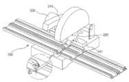
도 1은 본 발명에 따른 V절곡홈을 통한 LED 간판 제작장치를 도시한 구성요소를 도시한 사시도에 관한 것으로, 이는 알루미늄 플레이트부(100)와, V절곡 커터기(200)로 구성된다.1 is a perspective view showing the components showing the LED signboard manufacturing apparatus through the V-bending groove according to the present invention, which is composed of an
먼저, 본 발명에 따른 알루미늄 플레이트부(100)에 관해 설명한다.First, the
상기 알루미늄 플레이트부(100)는 장방형의 직사각형상으로 알루미늄 본체가 이루어지고, 내부에 제1 넥산광 PC, 알루미늄 각 파이프, LED 모듈, 제2 넥산광PC, 포맥스판을 지지하는 지지날개부가 가로방향으로 복수개로 돌출되어 형성되고, 지지날개부를 따라 세로방향으로 V절곡 커터기를 통해 형성된 전면용 V절곡홈, 후면용 V절곡홈, 좌측면용 V절곡홈, 우측면용 V절곡홈을 절곡시켜 전면, 후면, 좌측면, 우측면으로 이루어진 직사각형 블럭을 형성하는 것으로, 이는 제1 알루미늄 플레이트(110)와, 제2 알루미늄 플레이트(120)로 구성된다.The
본 발명에 따른 알루미늄 플레이트부(100)는 전면용 V절곡홈, 후면용 V절곡홈, 좌측면용 V절곡홈, 우측면용 V절곡홈을 절곡시켜 전면, 후면, 좌측면, 우측면으로 이루어진 직사각형 블럭(110a,110b)을 형성한 후, 제1 지지날개부와 제2 지지 날개부 일측에 복수개의 알루미늄각파이프를 직결피스로 고정시켜 외압에 의해 흔들리지 않도록 구성된다.
상기 직사각형 블럭(100a,110b)은 도 18 및 도 20에서 도시한 바와 같이, 벽면과 접촉되는 후면 일측에 벽걸이 부착걸이(100a-1)가 복수개로 형성된다.As shown in FIGS. 18 and 20, the
여기서, 벽걸이 부착걸이(100a-1)는 벽면에 미리 부착된 벽걸이 안착걸이(100a-2)와 짝을 이루며 탈부착식으로 연결된다.Here, the wall mounting hook (100a-1) is mated with the wall mounting mounting hook (100a-2) pre-attached to the wall surface is connected detachably.
상기 벽걸이 부착걸이(100a-1)는 직사각형 블럭(100a,110b) 중 후면 일측에 나사결합되어 고정되어, 벽면에 미리 부착된 벽걸이 안착걸이(100a-2)와 짝을 이루며 탈부착식으로 연결되는 것으로, 이는 도 21에서 도시한 바와 같이, 상단에 "

상기 벽걸이 안착걸이(100a-2)는 벽면에 벽고정용 볼트로 고정되어, 전면발광용 LED 간판의 후면 및 상·하 양면 발광용 LED 간판의 후면에 설치된 벽걸이 부착걸이(100a-1)가 안착되도록 안내한 후, 지지하는 역할을 한다.The wall mounting bracket (100a-2) is fixed to the wall with a bolt for fixing the wall, the wall mounting bracket (100a-1) is installed on the rear of the LED sign for the front and rear double-sided light emitting LED sign for mounting the wall Guide them as much as possible and then support them.
이는 도 22에서 도시한 바와 같이, 벽고정용 볼트에 삽입되어 너트로 체결되도록 벽고정용 볼트 삽입홈(100a-2a)이 형성된 상단돌출편(100a-2b)이 형성되고, 상단돌출편 하단에 벽걸이 부착걸이(100a-1)의 상단걸이부가 끼워져 안착되도록 "

상기 제1 알루미늄 플레이트(110)는 절단면이 "
본 발명에 따른 제1 알루미늄 플레이트(110)는 전면발광용 LED 간판을 제작하기 위한 것으로, 절단면 본체의 상단에서 하단까지 복수개의 제1 지지날개부가 일체형으로 금형제작된다.The
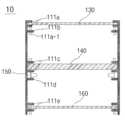
상기 제1 지지날개부(111)는 도 2에서 도시한 바와 같이, 절단면 본체의 상단에서 하단까지 제1 넥산광 PC용 지지날개(111a), 직결피스용 지지날개(111b), 제1 LED 모듈용 지지날개(111c), 제1 알루미늄각파이프용 지지날개(111d), 포맥스판용 지지날개(111e)로 구성된다.As shown in FIG. 2, the
상기 제1 넥산광 PC용 지지날개(111a)는 절단면 본체의 상단 일측에 형성되어, 제 LED 모듈을 통해 전면 발광시키는 넥산광 PC를 지지하는 역할을 한다.The first NEXEN LIGHT
상기 직결피스용 지지날개(111b)는 넥산광 PC 지지날개 하단에 형성되어, 넥산광 PC용 지지날개에 삽입된 넥산광 PC를 직결피스를 통해 지지하는 역할을 한다.The
상기 제1 LED 모듈용 지지날개(111c)는 절단면 본체의 중단 일측에 형성되어, LED 모듈을 지지하는 역할을 한다.The
상기 제1 알루미늄각파이프용 지지날개(111d)는 LED 모듈용 지지날개 하단에 형성되어, 알루미늄각파이프를 지지하는 역할을 한다.The
상기 포맥스판용 지지날개(111e)는 절단면 본체의 하단 일측에 형성되어, 포맥스판을 직결피스로 고정시키는 역할을 한다.The
상기 제2 알루미늄 플레이트(120)는 절단면이 "
본 발명에 따른 제2 알루미늄 플레이트(120)는 상·하 양면발광용 LED 간판을 제작하기 위한 것으로, 절단면 본체의 상단에서 하단까지 복수개의 제2 지지날개부가 일체형으로 금형제작된다.The
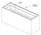
상기 제2 지지날개부(121)는 도 3에 도시한 바와 같이, 제1 넥산광 PC용 지지날개(121a), 제1 알루미늄각파이프용 지지날개(121b), 제2 알루미늄각파이프용 지지날개(121c), LED 모듈용 지지날개(121d), 제2 넥산광 PC용 지지날개(121e)로 구성된다.As shown in FIG. 3, the second
상기 제1 넥산광 PC용 지지날개(121a)는 절단면 본체의 상단 일측에 요홈형상으로 형성되어, LED 모듈을 통해 상면 발광시키는 제1 넥산광 PC가 덮개식으로 덮여지도록 안내하는 역할을 한다.The first NEXEN LIGHT
여기서, 요홈형상은 "
상기 제1 알루미늄각파이프용 지지날개(121b)는 제1 넥산광 PC용 지지날개 하단에 형성되어, 제1 알루미늄각파이프를 지지하는 역할을 한다.The
상기 제2 알루미늄각파이프용 지지날개(121c)는 절단면 본체의 중단 일측에 형성되어, 제2 알루미늄각파이프를 직결피스로 지지하는 역할을 한다.The second wing of the
상기 LED 모듈용 지지날개(121d)는 제2 알루미늄각파이프용 지지날개와 이웃되게 형성되어, LED 모듈을 직결피스로 지지하는 역할을 한다.The
상기 제2 넥산광 PC용 지지날개(121e)는 절단면 본체의 하단 일측에 형성되어, LED 모듈을 통해 하면(下面) 발광시키는 제2 넥산광 PC를 직결피스을 통해 지지하는 역할을 한다.The second NEXEN LIGHT
여기서, 제2 넥산광 PC용 지지날개(121e)는 "
상기 제2 넥산광 PC(170)는 단면형상이 "
여기서, 덮개판(171)은 도 16에서 도시한 바와 같이, 단면형상이 "
그리고, 도 14에서 도시한 바와 같이, 상기 덮개판(171)은 V절곡 커터기(200)를 통해 형성된 전면용 V절곡홈(171-1), 후면용 V절곡홈(171-2), 좌측면용 V절곡홈(171-3), 우측면용 V절곡홈(171-4)을 형성한 후 절곡시키고, 도 15에서 도시한 바와같이, 전면, 후면, 좌측면, 우측면으로 이루어진 직사각형 블럭(171a)을 형성한 후, 제2 넥산광 PC를 덮개판(171)의 측면 끼움홈(171-1a)에 끼워서 직결피스로 고정시킨다.And, as shown in Figure 14, the
그리고, 덮개식으로 형성된 제2 넥산광 PC(170)는 도 16에서 도시한 바와 같이, 단면형상이 "
다음으로, 본 발명에 따른 V절곡 커터기(200)에 관해 설명한다.Next, the V-
상기 V절곡 커터기(200)는 도 5에서 도시한 바와 같이, 알루미늄 플레이트부의 전면 기준선, 후면 기준선, 좌측면 기준선, 우측면 기준선에 V커팅날을 통해 세로방향으로 전면용 V절곡홈, 후면용 V절곡홈, 좌측면용 V절곡홈, 우측면용 V절곡홈을 형성하는 역할을 한다.The V-
이는 도 4에서 도시한 바와 같이, 손잡이형 커터기 본체(210)로 이루어지고, 본체의 커터기 날이 V커팅날(220)로 형성되고, V커팅날 일측에 회전모터(230)가 형성되며, V커팅날 하단에 알루미늄 플레이트부를 고정시키고 지지하는 지지판(240) 이 형성된다.As shown in Figure 4, it is made of a handle-
그리고, 지지판(240)은 일측에 V절곡 커터기가 알루미늄 플레이트부 표면을 0.2~0.8mm 깊이로만 커트시켜 절곡선이 형성되도록 절곡선용 보조판(241)이 형성된다.In addition, the
여기서, 절곡선용 보조판(241)이 형성됨으로서, 도 5 및 도 6에서 도시한 바와 같이, V절곡 커터기가 알루미늄 플레이트부 표면을 0.2~0.8mm 깊이로만 커트되도록 잡아줌으로서, 알루미늄 플레이트부를 통째로 절단시키는 것이 아니라, 표면을 0.2~0.8mm 깊이로만 커트시켜 절곡선을 형성할 수가 있다.Here, the bend line
본 발명에 따른 V절곡 커터기를 통해 알루미늄 플레이트부에 형성된 전면용 V절곡홈, 후면용 V절곡홈, 좌측면용 V절곡홈, 우측면용 V절곡홈은 V절곡각도가 30°~150°로 형성되고, V절곡홈 깊이가 표면에서 0.2~0.8mm 깊이로 형성된다.V bending groove for the front, V bending groove for the rear, V bending groove for the left side, V bending groove for the right side is formed by the V bending angle of 30 ° ~ 150 ° through the V bending cutter according to the present invention. , V bending groove depth is formed 0.2 ~ 0.8mm deep from the surface.
여기서, V절곡홈의 V절곡각도가 30°~150°로 형성되는 이유는 V절곡각도가 30°이하에서는 전면용 V절곡홈, 후면용 V절곡홈, 좌측면용 V절곡홈, 우측면용 V절곡홈을 절곡시키더라도, 절곡각도가 서로 맞지않아 전면, 후면, 좌측면, 우측면으로 이루어진 직사각형상의 블럭을 만들수가 없고, V절곡각도가 150°이상에서는 전면용 V절곡홈, 후면용 V절곡홈, 좌측면용 V절곡홈, 우측면용 V절곡홈이 과도하게 절곡되어, 절곡후 V절곡홈 후단이 끊어져서 절단되는 문제점이 발생되기 때문에, V절곡홈의 V절곡각도가 30°~150°로 형성되는 것이 가장 바람직하다.Here, the reason why the V bending angle of the V bending groove is formed to be 30 ° to 150 ° is that the V bending angle is less than 30 °, the front V bending groove, the rear V bending groove, the left side V bending groove, and the right side V bending Even when the grooves are bent, the bending angles do not match each other, so it is impossible to make a rectangular block consisting of the front, rear, left, and right sides. If the V bending angle is 150 ° or more, the front V bending groove, the rear V bending groove, V bending groove for the left side, V bending groove for the right side is excessively bent, so that the problem occurs that the rear end of the V bending groove is cut after bending, so that the V bending angle of the V bending groove is formed at 30 ° to 150 °. Most preferred.
그리고, V절곡홈 깊이가 표면에서 0.2~0.8mm 깊이로 형성되는 이유는 알루미늄 플레이트부의 두께에 따라 설정된 것으로, 0.2mm 이하의 깊이로 V절곡홈을 형성 하면, 절곡시, 절곡이 잘 되지 않는 문제점이 있고, 0.8mm 이상의 깊이로 V절곡홈을 형성하면, 절곡시, V절곡홈 후단이 끊어져서 절단되는 문제점이 발생되기 때문에, V절곡홈 깊이가 표면에서 0.2~0.8mm 깊이로 형성되는 것이 가장 바람직하다.The reason why the V-bending groove depth is 0.2 to 0.8 mm deep from the surface is set according to the thickness of the aluminum plate, and when the V-bending groove is formed to a depth of 0.2 mm or less, the bending is difficult when bending. In this case, when the V-bending groove is formed to a depth of 0.8 mm or more, a problem arises in that the rear end of the V-bending groove is cut when bending, and therefore, it is most preferable that the V-bending groove depth is formed to be 0.2 to 0.8 mm deep from the surface. Do.
이하, 본 발명에 따른 V절곡홈을 통한 LED 간판 제작방법에 관해 설명한다.Hereinafter, a method of manufacturing the LED signboard through the V-bending groove according to the present invention.
[전면발광용 LED 간판 제작방법][Production method of LED sign for front light emission]
도 21은 본 발명에 따른 V절곡홈을 통한 전면발광용 LED 간판 제작방법을 도시한 순서도에 관한 것이다.21 is a flowchart illustrating a method for manufacturing a front light emitting LED signage through a V-bending groove according to the present invention.
먼저, 도 6에 도시한 바와 같이, 절단면이 "
이어서, 도 9에 도시한 바와 같이, 제1 알루미늄 플레이트에 형성된 전면용 V절곡홈, 후면용 V절곡홈, 좌측면용 V절곡홈, 우측면용 V절곡홈을 절곡시켜 전면, 후면, 좌측면, 우측면으로 이루어진 직사각형 블럭을 형성한다.Then, as shown in Figure 9, the front V bent groove, the rear V bent groove, the left side V bent groove, the right side V bent groove formed in the first aluminum plate by bending the front, rear, left side, right side To form a rectangular block consisting of.
이어서, 도 11에서 도시한 바와 같이, 직사각형 블럭 내부에 형성된 제1 지지날개부 중 제1 알루미늄각파이프용 지지날개에 복수개의 제1 알루미늄각파이프를 직결피스로 고정시킨다.Subsequently, as shown in FIG. 11, a plurality of first aluminum angle pipes are fixed to the support wings for the first aluminum angle pipes among the first support wings formed in the rectangular block by the direct connection pieces.
이어서, 직사각형 블럭 내부에 형성된 제1 지지날개부 중 제1 넥산광 PC용 지지날개에 제1 넥산광 PC를 끼워 넣은 후, 제1 직결피스용 지지날개를 통해 관통된 직결피스로 제1 넥산광 PC를 고정시킨다.Subsequently, after inserting the first NEXAN light PC into the first NEXAN light PC support wing among the first support wings formed in the rectangular block, the first NEXAN light is passed through the direct connection piece through the support wing for the first direct connection piece. Secure your PC.
이어서, 직사각형 블럭 내부에 형성된 제1 지지날개부 중 제1 LED 모듈용 지지날개에 제1 LED 모듈을 끼워 넣은 후, 직결피스로 고정시킨다.Subsequently, the first LED module is inserted into the first wing of the first LED module among the first wing portions formed in the rectangular block, and then fixed with a direct connection piece.
끝으로, 도 12에서 도시한 바와 같이, 직사각형 블럭 내부에 형성된 제1 지지날개부 중 포맥스판용 지지날개에 포맥스판을 끼워 넣은 후, 직결피스로 고정시켜서 전면발광용 LED 간판 제작을 완료한다.Finally, as shown in FIG. 12, the Formax plate is inserted into the support blade for the Pomax plate among the first support wings formed in the rectangular block, and then fixed with a direct connection piece to complete the manufacture of the front light emitting LED sign.
[상·하 양면 발광용 LED 간판 제작방법][Manufacturing method of LED signage for both upper and lower side light emission]
도 21은 본 발명에 따른 V절곡홈을 통한 상·하 양면 발광용 LED 간판 제작방법을 도시한 순서도에 관한 것이다.21 is a flowchart illustrating a method of manufacturing a LED sign for up and down double-sided light emission through a V-bending groove according to the present invention.
먼저, 도 6에 도시한 바와 같이, 절단면이 "
이어서, 제2 알루미늄 플레이트에 형성된 전면용 V절곡홈, 후면용 V절곡홈, 좌측면용 V절곡홈, 우측면용 V절곡홈을 절곡시켜 전면, 후면, 좌측면, 우측면으로 이루어진 직사각형 블럭을 형성한다.Subsequently, the front V-bending groove, rear V-bending groove, left-side V-bending groove and right-side V-bending groove formed on the second aluminum plate are bent to form a rectangular block including the front, rear, left and right surfaces.
이어서, 직사각형 블럭 내부에 형성된 제2 지지날개부 중 제2 알루미늄각파이프용 지지날개에 복수개의 제2 알루미늄각파이프를 직결피스로 고정시킨다.Subsequently, a plurality of second aluminum square pipes are fixed to the support blades for the second aluminum square pipes among the second supporting blade portions formed inside the rectangular block with the direct connection pieces.
이어서, 직사각형 블럭 내부에 형성된 제2 지지날개부 중 제3 알루미늄각파이프용 지지날개에 복수개의3 제P알루미늄각파이프를 직결피스로 고정시킨다.Subsequently, a plurality of third P aluminum square pipes are fixed to the support blades for the third aluminum square pipes among the second supporting blade portions formed inside the rectangular block with a direct connection piece.
이어서, 직사각형 블럭 내부에 형성된 제2 지지날개부 중 제2 LED 모듈용 지지날개에 제2 LED 모듈을 끼워 넣은 후, 직결피스로 고정시킨다.Subsequently, the second LED module is inserted into the second LED module support blade among the second support wings formed in the rectangular block, and then fixed with a direct connection piece.
이어서, 직사각형 블럭 내부에 형성된 제2 지지날개부 중 제3 넥산광 PC용 지지날개에 제3 넥산광 PC를 끼워 넣은 후, 직결피스로 고정시킨다.Subsequently, after inserting the 3rd NEXAN light PC into the 3rd NEXAN light PC support wing among the 2nd support wing parts formed in the inside of a rectangular block, it fixes with a direct connection piece.
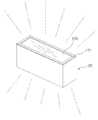
끝으로, 도 12에서 도시한 바와 같이, 직사각형 블럭 내부에 형성된 제2 지지날개부 중 제2 넥산광 PC용 지지날개에 제2 넥산광 PC를 덮개식으로 덮어서 상·하 양면 발광용 LED 간판 제작을 완료한다.Lastly, as shown in FIG. 12, the second NEXON light PC support wing is covered with a cover of the second NEXAN light PC among the second support wings formed in the rectangular block to manufacture LED signs for upper and lower side light emission. To complete.
[전면용 LED 간판 및 상·하 양면 발광용 LED 간판의 후면에 벽걸이 부착걸이(100a-1)를 형성하여 벽면에 거는 과정][The process of hanging on the wall by forming a wall-mounting hook (100a-1) on the back of the front LED sign and the upper and lower double-sided LED sign
먼저, 벽면에 벽고정용 볼트를 삽입한다.First, insert the wall fixing bolt into the wall.
이어서, 벽걸이 안착걸이(100a-2)에 벽고정용 볼트 삽입홈을 형성한 후, 벽고정용 볼트 삽입홈에 벽고정용 볼트를 삽입시키고, 너트로 체결시켜 벽면에 벽걸이 안착걸이(100a-2)를 고정시킨다.Subsequently, after the wall fixing bolt insertion groove is formed in the
이어서, 전면용 LED 간판의 후면 및 상·하 양면 발광용 LED 간판의 후면에 형성된 벽걸이 부착걸이(100a-1)를 벽걸이 안착걸이(100a-2)에 안착시킨다.Subsequently, the wall-mounted
이로 인해, 도 23 및 도 24에 도시한 바와 같이, 전면용 LED 간판 및 상·하 양면 발광용 LED 간판을 벽면에 손쉽게 설치할 수 있고, 수리 및 보수 작업시, 벽면과 손쉽게 분리시킬 수 있다.Thus, as shown in Figs. 23 and 24, the front LED sign and the upper and lower double-sided light emitting LED sign can be easily installed on the wall, and can be easily separated from the wall during repair and maintenance work.
도 1은 본 발명에 따른 V절곡홈을 통한 LED 간판 제작장치를 도시한 구성요소를 도시한 사시도,1 is a perspective view showing the components showing the LED signboard manufacturing apparatus through the V-bending groove according to the present invention,
도 2는 본 발명에 따른 제1 알루미늄 플레이트(110)의 구성요소를 도시한 단면도,2 is a cross-sectional view showing the components of the
도 3은 본 발명에 따른 제2 알루미늄 플레이트(210)의 구성요소를 도시한 단면도,3 is a cross-sectional view showing the components of the
도 4는 본 발명에 따른 V절곡 커터기(200)의 구성요소를 도시한 사시도,4 is a perspective view showing the components of the V-
도 5는 본 발명에 따른 알루미늄 플레이트부의 전면 기준선, 후면 기준선, 좌측면 기준선, 우측면 기준선을 형성하고, V절곡 커터기(200)의 지지판에 지지시키는 것을 도시한 일실시예도,FIG. 5 is a view illustrating an example of forming a front reference line, a rear reference line, a left reference line, a right reference line, and supporting the support plate of the V-
도 6은 본 발명에 따른 V절곡 커터기(200)를 통해 알루미늄 플레이트부의 전면 기준선, 후면 기준선, 좌측면 기준선, 우측면 기준선에 V커팅날을 통해 세로방향으로 전면용 V절곡홈, 후면용 V절곡홈, 좌측면용 V절곡홈, 우측면용 V절곡홈을 형성하는 과정을 도시한 일실시예도,Figure 6 is a front bending line for the front V, the rear V reference groove, the rear reference line, the left reference line, the right side reference line through the V-
도 7은 본 발명에 따른 V절곡 커터기(200)를 통해 제1 알루미늄 플레이트(110)에 전면용 V절곡홈, 후면용 V절곡홈, 좌측면용 V절곡홈, 우측면용 V절곡홈이 형성된 것을 도시한 일실시예도,7 shows that the front V bending groove, the rear V bending groove, the left side V bending groove, and the right side V bending groove are formed in the
도 8은 본 발명에 따른 V절곡 커터기(200)를 통해 제2 알루미늄 플레이트(210)에 전면용 V절곡홈, 후면용 V절곡홈, 좌측면용 V절곡홈, 우측면용 V절곡홈 이 형성된 것을 도시한 일실시예도,8 shows that the front V bending groove, the rear V bending groove, the left side V bending groove, and the right side V bending groove are formed in the
도 9는 전면용 V절곡홈, 후면용 V절곡홈, 좌측면용 V절곡홈, 우측면용 V절곡홈이 형성된 제1 알루미늄 플레이트(110)를 절곡시키는 과정을 도시한 일실시예도,FIG. 9 is a view illustrating a process of bending the
도 10은 본 발명에 따른 전면용 V절곡홈, 후면용 V절곡홈, 좌측면용 V절곡홈, 우측면용 V절곡홈이 형성된 제1 알루미늄 플레이트(110)를 절곡시켜 직사각형 블럭(110a)을 형성하는 과정을 도시한 일실시예도,10 is to form a rectangular block (110a) by bending the
도 11은 본 발명에 따른 직사각형 블럭(110a)으로 형성된 제2 알루미늄 플레이트(210)의 내부 구성요소를 도시한 내부 절단면도,11 is an internal cutaway view showing the internal components of a
도 12는 본 발명에 따른 V절곡홈을 통한 LED 간판 제작장치를 통해 제작된 전면 발광용 LED 간판의 구성요소를 도시한 측단면도,12 is a side cross-sectional view showing the components of the front light emitting LED signboard manufactured through the LED signboard manufacturing apparatus through the V-bending groove according to the present invention;
도 13은 본 발명에 따른 전면용 V절곡홈, 후면용 V절곡홈, 좌측면용 V절곡홈, 우측면용 V절곡홈이 형성된 제2 알루미늄 플레이트(210)를 절곡시켜 직사각형 블럭(210a)을 형성하는 과정을 도시한 일실시예도,13 is to form a rectangular block 210a by bending the
도 14는 본 발명에 따른 덮개판(171)을 V절곡 커터기(200)를 통해 전면용 V절곡홈(171-1), 후면용 V절곡홈(171-2), 좌측면용 V절곡홈(171-3), 우측면용 V절곡홈(171-4)을 형성한 후 절곡시키는 과정을 도시한 일실시예도,14 shows the
도 15는 본 발명에 따른 덮개판(171)을 절곡시켜 전면, 후면, 좌측면, 우측면으로 이루어진 직사각형 블럭(171a)을 형성한 후, 제2 넥산광 PC를 덮개판(171)의 측면 끼움홈(171-1a)에 끼워서 직결피스로 고정시키는 것을 도시한 일실시예도,15 is formed by bending the
도 16은 본 발명에 따른 덮개판(171)의 내부 구성요소를 도시한 절단면도,16 is a cross-sectional view showing the internal components of the
도 17은 본 발명에 따른 V절곡홈을 통한 LED 간판 제작장치를 통해 제작 완료된 상·하 양면 발광용 LED 간판을 도시한 사시도,17 is a perspective view showing the LED sign for up and down double-sided light emission completed through the LED signboard manufacturing apparatus through the V-bending groove according to the present invention,
도 18은 본 발명에 따른 상·하 양면 발광용 LED 간판의 후면에 벽걸이 부착걸이(100a-1)를 형성한 후, 벽면에 미리 부착된 벽걸이 안착걸이(100a-2)와 짝을 이루며 탈부착식으로 연결되는 과정을 도시한 일실시예도,Figure 18 is formed on the rear of the upper and lower double-sided light emitting LED sign according to the present invention after forming the wall-mounting hook (100a-1), the mating with the wall-mounting mounting hook (100a-2) pre-attached to the wall surface detachable In one embodiment showing a process connected to,
도 19는 본 발명에 따른 V절곡홈을 통한 LED 간판 제작장치를 통해 제작 완료된 전면 발광용 LED 간판을 도시한 사시도,19 is a perspective view showing a front light emitting LED signboard manufactured through the LED signboard manufacturing apparatus through the V-bending groove according to the present invention;
도 20은 본 발명에 따른 전면 발광용 LED 간판의 후면에 벽걸이 부착걸이(100a-1)를 형성한 후, 벽면에 미리 부착된 벽걸이 안착걸이(100a-2)와 짝을 이루며 탈부착식으로 연결되는 과정을 도시한 일실시예도,Figure 20 is formed on the back of the front light emitting LED sign according to the present invention after forming the wall-mounted hook (100a-1), the wall is attached to the wall mounting hook (100a-2) pre-attached to the wall and detachably connected One embodiment showing the process,
도 21은 본 발명에 따른 벽걸이 부착걸이(100a-1)의 구성요소를 도시한 사시도,Figure 21 is a perspective view showing the components of the wall mounting hook (100a-1) according to the present invention,
도 22는 본 발명에 따른 벽걸이 안착걸이(100a-2)의 구성요소를 도시한 사시도,22 is a perspective view showing the components of the wall-mounted mounting hanger (100a-2) according to the present invention,
도 23은 본 발명에 따른 전면 발광용 LED 간판의 후면에 벽걸이 부착걸이(100a-1)와 벽걸이 안착걸이(100a-2)가 짝을 이루며 탈부착식으로 연결되는 과정을 도시한 일실시예도,FIG. 23 is a view illustrating a process in which a wall-mounting
도 24는 본 발명에 따른 상·하 양면 발광용 LED 간판의 후면에 벽걸이 부착걸이(100a-1)와 벽걸이 안착걸이(100a-2)가 짝을 이루며 탈부착식으로 연결되는 과정을 도시한 일실시예도,FIG. 24 is a diagram illustrating a process in which a wall-mounting
도 25는 본 발명에 따른 V절곡홈을 통한 LED 간판 제작장치를 통해 LED 모듈이 전면에서 발광되는 전면발광용 LED 간판 제작방법을 도시한 순서도,25 is a flowchart illustrating a method for manufacturing a front light emitting diode LED sign that the LED module is emitted from the front through the LED signboard manufacturing apparatus through the V-bending groove according to the present invention;
도 26은 본 발명에 따른 V절곡홈을 통한 LED 간판 제작장치를 통해 LED 모듈이 상하 양면에서 발광되는 상·하 양면 발광용 LED 간판 제작방법을 도시한 순서도.FIG. 26 is a flowchart illustrating a method of manufacturing LED signboards for both upper and lower sides, in which LED modules are emitted from both upper and lower sides through an LED signboard manufacturing apparatus through a V-bending groove according to the present invention. FIG.
※ 도면 부호의 간단한 설명 ※※ Brief description of reference numerals ※
100 : 알루미늄 플레이트부 110 : 제1 알루미늄 플레이트100: aluminum plate section 110: first aluminum plate
111 : 제1 지지날개부 111a : 제1 넥산광 PC용 지지날개111:
111b : 직결피스용 지지날개 111c : 제1 LED 모듈용 지지날개111b: Supporting wing for
111d : 제1 알루미늄각파이프용 지지날개111d: support wing for first aluminum square pipe
111e : 포맥스판용 지지날개 120 : 제2 알루미늄 플레이트111e: support blade for Formax plate 120: second aluminum plate
121 : 제2 지지날개부 121a : 제1 넥산광 PC용 지지날개121: 2nd
121b : 제1 알루미늄각파이프용 지지날개121b: support wing for the first aluminum square pipe
121c : 제2 알루미늄각파이프용 지지날개121c: support wing for the second aluminum square pipe
121d : LED 모듈용 지지날개 121e : 제2 넥산광 PC용 지지날개121d: Supporting wing for
200 : V절곡 커터기200: V bending cutter
Claims (11)
Translated fromKoreanPriority Applications (1)
| Application Number | Priority Date | Filing Date | Title |
|---|---|---|---|
| KR1020090114659AKR100949279B1 (en) | 2009-11-25 | 2009-11-25 | The apparatus and method of manufcature a led signboard |
Applications Claiming Priority (1)
| Application Number | Priority Date | Filing Date | Title |
|---|---|---|---|
| KR1020090114659AKR100949279B1 (en) | 2009-11-25 | 2009-11-25 | The apparatus and method of manufcature a led signboard |
Publications (1)
| Publication Number | Publication Date |
|---|---|
| KR100949279B1true KR100949279B1 (en) | 2010-03-25 |
Family
ID=42183719
Family Applications (1)
| Application Number | Title | Priority Date | Filing Date |
|---|---|---|---|
| KR1020090114659AExpired - Fee RelatedKR100949279B1 (en) | 2009-11-25 | 2009-11-25 | The apparatus and method of manufcature a led signboard |
Country Status (1)
| Country | Link |
|---|---|
| KR (1) | KR100949279B1 (en) |
Citations (4)
| Publication number | Priority date | Publication date | Assignee | Title |
|---|---|---|---|---|
| US5501013A (en) | 1990-09-04 | 1996-03-26 | Ppg Industries, Inc. | Spacer and spacer frame for an insulating glazing unit and method of making same |
| US20040071933A1 (en) | 2002-10-09 | 2004-04-15 | Mcconnell Anthony | Fabric covered pad for wall panel and forming process |
| KR200371436Y1 (en) | 2004-09-22 | 2005-01-03 | (주)애드라인 | advertising board structure |
| JP2005320205A (en) | 2004-05-10 | 2005-11-17 | Toshiba Corp | Method for joining strip glass plate and method for producing glass frame |
- 2009
- 2009-11-25KRKR1020090114659Apatent/KR100949279B1/ennot_activeExpired - Fee Related
Patent Citations (4)
| Publication number | Priority date | Publication date | Assignee | Title |
|---|---|---|---|---|
| US5501013A (en) | 1990-09-04 | 1996-03-26 | Ppg Industries, Inc. | Spacer and spacer frame for an insulating glazing unit and method of making same |
| US20040071933A1 (en) | 2002-10-09 | 2004-04-15 | Mcconnell Anthony | Fabric covered pad for wall panel and forming process |
| JP2005320205A (en) | 2004-05-10 | 2005-11-17 | Toshiba Corp | Method for joining strip glass plate and method for producing glass frame |
| KR200371436Y1 (en) | 2004-09-22 | 2005-01-03 | (주)애드라인 | advertising board structure |
Similar Documents
| Publication | Publication Date | Title |
|---|---|---|
| US9921368B2 (en) | Edge-lit light guide panel | |
| EP1948995B1 (en) | A luminaire comprising leds | |
| CA2636512A1 (en) | Led lighting assemblies for display cases | |
| KR100949279B1 (en) | The apparatus and method of manufcature a led signboard | |
| CN102635830A (en) | LED (Light-emitting Diode) line lamp | |
| KR102067578B1 (en) | Illuminating wall | |
| KR101032470B1 (en) | Modular LGP Lighting | |
| CN202511098U (en) | LED (Light-Emitting Diode) line lamp | |
| KR101171629B1 (en) | Side lighting structure of channel sign | |
| KR200434173Y1 (en) | Sliding and expanded light tile device | |
| KR100876576B1 (en) | Signboard Attachment | |
| JP3154755U (en) | Indirect lighting device | |
| KR200444709Y1 (en) | Sign board structure for character attachment | |
| CN217763270U (en) | OLED automobile lamp | |
| CN101660720A (en) | lamp box device | |
| KR20160066890A (en) | Channel sign constructing structure | |
| KR100786361B1 (en) | Manufacturing method of light diffusion epoxy LED surface emitting channel | |
| KR20170001886U (en) | Channel apparatus for outdoor advertising | |
| CN218494847U (en) | Ceiling lamp and atmosphere lamp | |
| KR20050111973A (en) | Mounting structure of emergency exit leading lamp | |
| WO2009119928A1 (en) | Traffic sign | |
| KR100943533B1 (en) | Signboard | |
| JP2009146608A (en) | Lighting device | |
| KR200309733Y1 (en) | Full color sign board | |
| CN216487187U (en) | Detachable marker light |
Legal Events
| Date | Code | Title | Description |
|---|---|---|---|
| A201 | Request for examination | ||
| PA0109 | Patent application | St.27 status event code:A-0-1-A10-A12-nap-PA0109 | |
| PA0201 | Request for examination | St.27 status event code:A-1-2-D10-D11-exm-PA0201 | |
| A302 | Request for accelerated examination | ||
| PA0302 | Request for accelerated examination | St.27 status event code:A-1-2-D10-D17-exm-PA0302 St.27 status event code:A-1-2-D10-D16-exm-PA0302 | |
| D13-X000 | Search requested | St.27 status event code:A-1-2-D10-D13-srh-X000 | |
| D14-X000 | Search report completed | St.27 status event code:A-1-2-D10-D14-srh-X000 | |
| E701 | Decision to grant or registration of patent right | ||
| PE0701 | Decision of registration | St.27 status event code:A-1-2-D10-D22-exm-PE0701 | |
| GRNT | Written decision to grant | ||
| PR0701 | Registration of establishment | St.27 status event code:A-2-4-F10-F11-exm-PR0701 | |
| PR1002 | Payment of registration fee | St.27 status event code:A-2-2-U10-U11-oth-PR1002 Fee payment year number:1 | |
| PG1601 | Publication of registration | St.27 status event code:A-4-4-Q10-Q13-nap-PG1601 | |
| FPAY | Annual fee payment | Payment date:20130115 Year of fee payment:4 | |
| PR1001 | Payment of annual fee | St.27 status event code:A-4-4-U10-U11-oth-PR1001 Fee payment year number:4 | |
| FPAY | Annual fee payment | Payment date:20140129 Year of fee payment:5 | |
| PR1001 | Payment of annual fee | St.27 status event code:A-4-4-U10-U11-oth-PR1001 Fee payment year number:5 | |
| PR1001 | Payment of annual fee | St.27 status event code:A-4-4-U10-U11-oth-PR1001 Fee payment year number:6 | |
| LAPS | Lapse due to unpaid annual fee | ||
| PC1903 | Unpaid annual fee | St.27 status event code:A-4-4-U10-U13-oth-PC1903 Not in force date:20160318 Payment event data comment text:Termination Category : DEFAULT_OF_REGISTRATION_FEE | |
| P22-X000 | Classification modified | St.27 status event code:A-4-4-P10-P22-nap-X000 | |
| PC1903 | Unpaid annual fee | St.27 status event code:N-4-6-H10-H13-oth-PC1903 Ip right cessation event data comment text:Termination Category : DEFAULT_OF_REGISTRATION_FEE Not in force date:20160318 | |
| P22-X000 | Classification modified | St.27 status event code:A-4-4-P10-P22-nap-X000 | |
| P22-X000 | Classification modified | St.27 status event code:A-4-4-P10-P22-nap-X000 | |
| P22-X000 | Classification modified | St.27 status event code:A-4-4-P10-P22-nap-X000 |