KR100944909B1 - Grommet - Google Patents
GrommetDownload PDFInfo
- Publication number
- KR100944909B1 KR100944909B1KR1020080017927AKR20080017927AKR100944909B1KR 100944909 B1KR100944909 B1KR 100944909B1KR 1020080017927 AKR1020080017927 AKR 1020080017927AKR 20080017927 AKR20080017927 AKR 20080017927AKR 100944909 B1KR100944909 B1KR 100944909B1
- Authority
- KR
- South Korea
- Prior art keywords
- coupling groove
- movable
- taping
- indoor
- grommet
- Prior art date
- Legal status (The legal status is an assumption and is not a legal conclusion. Google has not performed a legal analysis and makes no representation as to the accuracy of the status listed.)
- Expired - Fee Related
Links
Images


Classifications
- B—PERFORMING OPERATIONS; TRANSPORTING
- B60—VEHICLES IN GENERAL
- B60R—VEHICLES, VEHICLE FITTINGS, OR VEHICLE PARTS, NOT OTHERWISE PROVIDED FOR
- B60R16/00—Electric or fluid circuits specially adapted for vehicles and not otherwise provided for; Arrangement of elements of electric or fluid circuits specially adapted for vehicles and not otherwise provided for
- B60R16/02—Electric or fluid circuits specially adapted for vehicles and not otherwise provided for; Arrangement of elements of electric or fluid circuits specially adapted for vehicles and not otherwise provided for electric constitutive elements
- B60R16/0207—Wire harnesses
- B60R16/0215—Protecting, fastening and routing means therefor
- B60R16/0222—Grommets
- B—PERFORMING OPERATIONS; TRANSPORTING
- B60—VEHICLES IN GENERAL
- B60R—VEHICLES, VEHICLE FITTINGS, OR VEHICLE PARTS, NOT OTHERWISE PROVIDED FOR
- B60R16/00—Electric or fluid circuits specially adapted for vehicles and not otherwise provided for; Arrangement of elements of electric or fluid circuits specially adapted for vehicles and not otherwise provided for
- B60R16/02—Electric or fluid circuits specially adapted for vehicles and not otherwise provided for; Arrangement of elements of electric or fluid circuits specially adapted for vehicles and not otherwise provided for electric constitutive elements
- H—ELECTRICITY
- H01—ELECTRIC ELEMENTS
- H01B—CABLES; CONDUCTORS; INSULATORS; SELECTION OF MATERIALS FOR THEIR CONDUCTIVE, INSULATING OR DIELECTRIC PROPERTIES
- H01B17/00—Insulators or insulating bodies characterised by their form
- H01B17/56—Insulating bodies
- H01B17/58—Tubes, sleeves, beads, or bobbins through which the conductor passes
- H01B17/583—Grommets; Bushings
Landscapes
- Engineering & Computer Science (AREA)
- Mechanical Engineering (AREA)
- Installation Of Indoor Wiring (AREA)
- Insulating Bodies (AREA)
Abstract
Translated fromKoreanDescription
Translated fromKorean본 발명은 한번의 동작으로 차체에 용이하게 설치될 수 있는 그로멧에 관한 것이다.The present invention relates to a grommets that can be easily installed in a vehicle body in one operation.
일반적으로, 자동차의 구성은 크게 섀시와 보디로 구성되어 기계적으로 결합되어 있고, 제어용의 전기적인 신호나 구동에 필요한 전원을 공급하기 위해서 와이어하네스가 다량 사용되고 있다.In general, a vehicle is largely composed of a chassis and a body and mechanically coupled, and a large amount of wire harnesses are used to supply electric signals for control and power required for driving.
상기 구성의 와이어하네스는 자동차에서 필요로 하는 배선들을 집적하여 와이어형상으로 구성하여 전기적신호 혹은 전원을 필요로 하는 곳에 공급하고, 와이어형의 하네스는 패널과 패널사이처럼 극히 협소한 공간을 통과하고 그곳에서 여러각도로 절곡되어 사용된다.The wire harness of the above configuration integrates the wires required by the vehicle to form a wire shape and supplies it to an electric signal or a power source, and the wire harness passes through extremely narrow spaces such as between panels. It is used at various angles in.
상기와 같이, 와이어하네스를 패널에 형성된 홀에 그대로 통과시킬 경우 금속재로 이루어진 패널의 모서리부에 하네스가 손상을 입게 되어 전기적신호의 에러발생과 전원전달의 누전 등으로 정확한 제어가 이루어지지 못한다.As described above, when the wire harness is passed through the hole formed in the panel as it is, the harness is damaged at the corners of the panel made of metal, so that accurate control cannot be performed due to an error of an electrical signal and a short circuit of power transmission.
이와 같은 문제점을 해결하기 위해서 종래의 그로멧이 제안되었다.In order to solve this problem, the conventional grommets have been proposed.
도 1은 종래 그로멧의 단면도이다. 도 1에 도시된 바와 같이, 와이어하네스가 패널을 통과하는 부분에는 그 단면이 대략 깔대기형의 그로멧(1)을 삽입 고정하여 하네스의 외부면을 보호하고, 상기 그로멧(1)의 중심부에 형성된 홀을 통하여 하네스가 패널을 통과하도록 하고 있다.1 is a cross-sectional view of a conventional grommets. As shown in FIG. 1, the wire harness passes through the panel to secure the outer surface of the harness by inserting and fixing a
그리고, 상기 그로멧(1)은 와이어하네스의 보호 뿐만아니라 와이어하네스가 패널(2)을 관통하여 조립 후 물이나 기타 이물질이 패널(2)의 조립홀을 통하여 자동차의 실내로 유입되는 것을 방지하며, 엔진룸과 같은 외부소음의 유입도 차단하는 역할을 한다.In addition, the
상기와 같이 와이어하네스의 보호와 이물질 및 소음의 유입을 방지하는 그로멧(1)은 자동차의 조립라인에서 제작자동차에 필요한 하네스 공급물량과 동일하게 조립이 된다.As described above, the
그러나, 종래의 그로멧을 차체에 설치하기 위해서는 작업자가 그로멧을 차체에 정밀하게 설치하여야 하므로, 설치시간이 많이 소요되어 그로멧작업이 지연되는 문제점이 있다.However, in order to install the conventional grommets on the vehicle body, since the operator must install the grommets on the vehicle body precisely, there is a problem that a lot of installation time is required and the grommets work is delayed.
또한, 그로멧이 정확하게 고정되지 않은 상태에서 그로멧작업이 진행되면 불량이 발생되는 원인이 되었다.In addition, when the grommet work proceeds in a state where the grommet is not fixed correctly, it is a cause of failure.
따라서, 본 발명은 상기한 바와 같은 종래기술의 문제점을 해소하기 위해 안출한 것으로, 한번의 동작으로 차체에 용이하게 설치될 수 있는 그로멧을 제공하는 데 그 목적이 있다.Accordingly, an object of the present invention is to provide a grommets that can be easily installed in a vehicle body in one operation.
본 발명이 이루고자 하는 기술적 과제들은 이상에서 언급한 기술적 과제들로 제한되지 않으며, 언급되지 않은 또 다른 기술적 과제들은 아래의 기재로부터 본 발명이 속하는 기술분야에서 통상의 지식을 가진 자(이하 당업자)에게 명확하게 이해될 수 있을 것이다.Technical problems to be achieved by the present invention are not limited to the above-mentioned technical problems, and other technical problems not mentioned above are provided to those skilled in the art (hereinafter, those skilled in the art) from the following description. It will be clearly understood.
본 발명의 바람직한 실시예는 실내테이핑부(11)과; 실외테이핑부(12)와; 상기 실내테이핑부(11)에서 상기 실외테이핑부(12)까지 동일체로 연결되는 콘형상의 삽입몸체(13)와; 상기 삽입몸체(13)의 중간에서 외주면을 따라 형성된 원형의 결합홈(14)과; 상기 결합홈(14)에 삽입되는 가동몸체(151)와 상기 가동몸체(151)의 외주면에서 설정된 간격으로 이격되게 형성되는 다수개의 쐐기형상돌기(152)로 이루어져 상기 삽입몸체(13)를 차체(a)의 홀(b)에 고정시키도록 상기 결합홈(14)에 탈부착되는 가동편(15)와; 상기 결합홈(14)에서 설정된 간격만큼 이격되어 형성된 차체지지벽(17)을 포함하는 통상의 그로멧에 있어서,
상기 가동몸체(151)는, 반원형상의 제1몸체(153)와; 상기 제1몸체(153)와 대칭되는 제2몸체(154)와; 상기 제1몸체(153) 및 제2몸체(154)를 분리 및 결합시키는 체결부(155)와; 상기 제1몸체(153)의 양단에 형성되는 복수개의 암돌기(156)와; 상기 제2몸체(154)의 양단에 형성되며, 상기 복수개의 암돌기(156)와 대응되는 복수개의 수돌기(157)을 포함한다.Preferred embodiment of the present invention and the
The
본 발명은 한번의 동작으로 그로멧이 차체에 용이하게 설치될 수 있는 이점이 있다.The present invention has the advantage that the grommet can be easily installed in the vehicle body in one operation.
이하, 본 발명의 바람직한 실시예에 대하여 첨부도면을 참조하여 상세히 설명하기로 한다. 기타 실시예들의 구체적인 사항들은 상세한 설명 및 도면들에 포함되어 있다. 본 발명의 이점 및 특징, 그리고 그것들을 달성하는 방법은 첨부되는 도면과 함께 상세하게 후술되어 있는 실시예들을 참조하면 명확해질 것이다. 명세서 전체에 걸쳐 동일 참조 부호는 동일 구성 요소를 지칭한다.Hereinafter, exemplary embodiments of the present invention will be described in detail with reference to the accompanying drawings. Specific details of other embodiments are included in the detailed description and the drawings. Advantages and features of the present invention and methods for achieving them will be apparent with reference to the embodiments described below in detail with the accompanying drawings. Like reference numerals refer to like elements throughout.
본 발명의 바람직한 실시예에 대해 첨부된 도면을 참조로 상세히 설명한다.Preferred embodiments of the present invention will be described in detail with reference to the accompanying drawings.
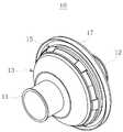
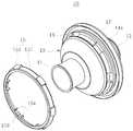
도 2는 본 발명의 바람직한 실시예에 따른 그로멧의 사시도이고, 도 3은 본 발명의 분해사시도이다.2 is a perspective view of a grommets according to a preferred embodiment of the present invention, Figure 3 is an exploded perspective view of the present invention.
도 2 및 도 3에 도시된 바와 같이, 본 발명에 따른 그로멧(10)은 실내테이핑부(11)와, 실외테이핑부(12)와, 실내테이핑부(11)에서 상기 실외테이핑부(12)까지 동일체로 연결되는 콘형상의 삽입몸체(13)와, 삽입몸체(13)의 중간에서 외주면을 따라 형성된 원형의 결합홈(14)과, 삽입몸체(13)를 차체(a)의 홀(b)에 고정시키도록 상기 결합홈(14)에 탈부착되는 가동편(15)과, 결합홈(14)에서 설정된 간격만큼 이격되어 형성된 차체지지벽(17)을 포함한다.As shown in FIGS. 2 and 3, the
여기서, 실내테이핑부(11)와 실외테이핑부(12)는 각각 차체(a)의 내측 및 외측에 위치된 상태에서 전선이 삽입되면 테이핑하여 전선을 고정시킬 수 있다.Here, the
그리고, 콘형상의 삽입몸체(13)는 실내테이핑부(11)를 향하는 형상이 좁게 형성되어 차체(a)의 홀(b)에 용이하게 삽입될 수 있다.In addition, the cone-
또한, 결합홈(14)은 삽입몸체(13)의 외주면에 형성되어 가동편(15)이 결합될 수 있다. 즉, 가동편(15)은 연성의 합성수지재로 제작될 수 있고, 삽입몸체(13)는 고무로 제작될 수 있으므로, 합성수지의 연성과 고무의 신축성에 의하여 가동편(15)과 삽입몸체(13)는 용이하게 결합될 수 있다.In addition, the
그리고, 결합홈(14)에는 설정된 간격으로 다수개의 체결홈(14a)이 형성되고, 가동몸체(151)는 후방에 체결홈(14a)에 삽입되는 다수개의 체결돌기(15a)가 형성될 수 있다. 즉, 다수개의 체결홈(14a)에 다수개의 체결돌기(15a)가 결합되면 가동편(15)은 결합홈(14)에서 회전되지 않는다. 따라서, 가동편(15)이 결합홈(14)에서 회전되지 않게 되므로, 가동편(15)과 삽입몸체(13)는 일체로 구성될 수 있어 견고하게 형상을 유지할 수 있다. 또한, 가동편(15)과 결합홈(14)이 상호 유동되지 않으므로, 긴밀성이 증대되어 수밀성이 상승하는 효과도 있다.In addition, the
그리고, 가동편(15)은 상기 결합홈(14)에 삽입되는 가동몸체(151)와, 가동몸체(151)의 외주면에서 설정된 간격으로 이격되게 형성되는 다수개의 쐐기형상돌기(152)를 포함하여 구성될 수 있다.In addition, the
여기서, 가동몸체(151)는 링형상으로 제작되는 것이 바람직하다. 그리고, 가동몸체(151)를 실내테이핑부(11)에서 삽입몸체(13)로 밀어 넣으면 가동몸체(151)는 결합홈(14)에 결합될 수 있다.Here, the
이와 같이, 가동몸체(151)가 결합된 삽입몸체(13)를 차체(a)의 홀(b)에 삽입시키는 한번의 동작에 의해 삽입몸체(13)는 홀(b)에 고정될 수 있다. 즉, 삽입몸체(13)를 홀(b)에 삽입시키면 가동몸체(151)의 쐐기형상돌기(152)가 홀(b)에 걸리게되어 삽입몸체(13)는 홀(b)에 고정될 수 있다.As such, the
따라서, 홀(b)의 내측에는 쐐기형상돌기(152)가 지지되고, 홀(b)의 외측에는 차체지지벽(17)이 위치되므로, 삽입몸체(13)는 쐐기형상돌기(152)와 차체지지벽(17)에 의해 홀(b)에 고정되게 위치될 수 있다. 이때, 차체지지벽(17)은 다수개의 쐐기형상돌기(152)와 대응되도록 원형형상으로 제작되는 것이 바람직하다.Therefore, since the wedge-
이때, 쐐기형상돌기(152)는 뒤로 접혀졌다가 다시 복원되도록 제작될 수 있으므로, 삽입몸체(13)가 홀(b)에 삽입되는 과정에서 접혀지는 동작이 이루어지고, 연이어서 삽입몸체(13)가 홀(b)에 삽입된 후에는 펴지는 동작이 이루어질 수 있다.At this time, since the wedge-
따라서, 작업자는 그로멧 설치작업을 한 번의 동작으로 신속하게 수행할 수 있다. Thus, the operator can quickly perform the grommet installation work in one operation.
도 4는 본 발명의 다른 실시예를 따른 요부를 보인 배면도이고, 도 5는 도 4의 분리된 상태를 보인 배면도이며, 도 6은 본 발명의 사용상태를 보인 단면도이다.Figure 4 is a rear view showing the main portion according to another embodiment of the present invention, Figure 5 is a rear view showing the separated state of Figure 4, Figure 6 is a cross-sectional view showing a use state of the present invention.
그리고, 도 4 내지 도 6에 도시된 바와 같이, 가동몸체(151)는 반원형상의 제1몸체(153)와, 제1몸체(153)와 대칭되는 제2몸체(154)와, 제1몸체(153) 및 제2몸체(154)를 분리 및 결합시키는 체결부(155)를 포함하여 구성할 수 있다.4 to 6, the
여기서, 가동몸체(151)는 서로 대칭되는 반원형상으로 분리시켜 제작할 수 있다. 이때, 반원형상으로 분리된 가동몸체(151)각각의 양단을 체결부(155)를 이용하여 결합시킨 후에 삽입몸체(13)에 결합시킬 수 있다.Here, the
또는, 분리된 가동몸체(151)를 삽입몸체(13)에 대칭되게 위치시킨 상태에서 체결부(155)를 이용하여 결합시킬 수도 있다.Alternatively, the separated
그리고, 체결부(155)는 제1몸체(153)의 양단에 형성되는 복수개의 암돌 기(156)와, 제2몸체(154)의 양단에 형성되며, 상기 복수개의 암돌기(156)와 대응되는 복수개의 수돌기(157)를 포함하여 구성될 수 있다.In addition, the
여기서, 복수개의 암돌기(156)와 복수개의 수돌기(157)를 결합하는 것으로, 가동몸체(151)는 삽입몸체(13)에 용이하게 결합될 수 있다.Here, by combining the plurality of
한편, 제1몸체(153) 및 제2몸체(154)의 각각의 양단에 힌지(미도시)를 설치할 수도 있다. 즉, 힌지에 의해 회전되는 가동몸체(151)를 이용하면 삽입몸체(13)에 가동몸체(151)를 더욱 빠르게 설치할 수 있다.Meanwhile, hinges (not shown) may be provided at both ends of the
이와 같이 구성된, 본 발명은 콘형상으로 형성된 그로멧에 형성된 다수개의 장홈에 의해 그로멧이 신축되어, 한번의 동작으로 그로멧은 용이하게 차체에 설치될 수 있다.In this way, the present invention is that the grommet is stretched by a plurality of long grooves formed in the cone-shaped grommet, the grommet can be easily installed in the vehicle body in one operation.
이상, 본 발명을 본 발명의 원리를 예시하기 위한 바람직한 실시예와 관련하여 설명하고 도시하였지만, 본 발명은 그와 같이 도시되고 설명된 그대로의 구성 및 작용으로 한정되는 것이 아니다.While the invention has been described and illustrated in connection with a preferred embodiment for illustrating the principles of the invention, the invention is not limited to the configuration and operation as such is shown and described.
오히려, 첨부된 청구범위의 사상 및 범주를 일탈함이 없이 본 발명에 대한 다수의 변경 및 수정이 가능함을 당업자들은 잘 이해할 수 있을 것이다.Rather, it will be apparent to those skilled in the art that many changes and modifications to the present invention are possible without departing from the spirit and scope of the appended claims.
따라서, 그러한 모든 적절한 변경 및 수정과 균등물들도 본 발명의 범위에 속하는 것으로 간주되어야 할 것이다.Accordingly, all such suitable changes and modifications and equivalents should be considered to be within the scope of the present invention.
도 1은 도 1은 종래 그로멧의 단면도,1 is a cross-sectional view of the
도 2는 본 발명의 바람직한 실시예에 따른 그로멧의 사시도,2 is a perspective view of a grommets according to a preferred embodiment of the present invention,
도 3은 본 발명의 분해사시도,3 is an exploded perspective view of the present invention;
도 4는 본 발명의 다른 실시예를 따른 요부를 보인 배면도,Figure 4 is a rear view showing the main portion according to another embodiment of the present invention,
도 5는 도 4의 분리된 상태를 보인 배면도,Figure 5 is a rear view showing the separated state of FIG.
도 6은 본 발명의 사용상태를 보인 단면도.Figure 6 is a cross-sectional view showing a state of use of the present invention.
<도면의 주요부분에 대한 부호의 설명><Description of the symbols for the main parts of the drawings>
10 : 그로멧11 : 실내테이핑부10: Grommet 11: Indoor taping part
12 : 실외테이핑부13 : 삽입몸체12: outdoor tape portion 13: insert body
15 : 가동편17 : 차체지지벽15: movable piece 17: body support wall
Claims (5)
Translated fromKoreanPriority Applications (1)
| Application Number | Priority Date | Filing Date | Title |
|---|---|---|---|
| KR1020080017927AKR100944909B1 (en) | 2008-02-27 | 2008-02-27 | Grommet |
Applications Claiming Priority (1)
| Application Number | Priority Date | Filing Date | Title |
|---|---|---|---|
| KR1020080017927AKR100944909B1 (en) | 2008-02-27 | 2008-02-27 | Grommet |
Publications (2)
| Publication Number | Publication Date |
|---|---|
| KR20090092596A KR20090092596A (en) | 2009-09-01 |
| KR100944909B1true KR100944909B1 (en) | 2010-03-03 |
Family
ID=41301143
Family Applications (1)
| Application Number | Title | Priority Date | Filing Date |
|---|---|---|---|
| KR1020080017927AExpired - Fee RelatedKR100944909B1 (en) | 2008-02-27 | 2008-02-27 | Grommet |
Country Status (1)
| Country | Link |
|---|---|
| KR (1) | KR100944909B1 (en) |
Cited By (2)
| Publication number | Priority date | Publication date | Assignee | Title |
|---|---|---|---|---|
| KR200477642Y1 (en)* | 2013-11-14 | 2015-07-07 | 주식회사 유라코퍼레이션 | Assembling type duplication grommet for decreasing noise |
| US11404185B2 (en)* | 2020-02-03 | 2022-08-02 | Yazaki Corporation | Water-stop grommet and wire harness |
Families Citing this family (28)
| Publication number | Priority date | Publication date | Assignee | Title |
|---|---|---|---|---|
| KR102151412B1 (en) | 2014-03-31 | 2020-10-27 | 엘지디스플레이 주식회사 | White organic light emitting device |
| KR102162259B1 (en) | 2014-05-26 | 2020-10-07 | 엘지디스플레이 주식회사 | White organic light emitting device |
| KR102272943B1 (en) | 2014-09-17 | 2021-07-05 | 엘지디스플레이 주식회사 | White organic light emitting device |
| KR102214339B1 (en) | 2014-10-01 | 2021-02-10 | 엘지디스플레이 주식회사 | White organic light emitting device |
| EP3016159B1 (en) | 2014-10-27 | 2021-12-08 | LG Display Co., Ltd. | White organic light emitting device |
| KR102387097B1 (en) | 2014-10-27 | 2022-04-18 | 엘지디스플레이 주식회사 | White organic light emitting device |
| KR102272053B1 (en) | 2014-10-28 | 2021-07-02 | 엘지디스플레이 주식회사 | White organic light emitting device |
| CN105609527B (en) | 2014-11-13 | 2019-04-30 | 乐金显示有限公司 | Organic Light Emitting Display Device |
| KR102358545B1 (en) | 2014-11-13 | 2022-02-04 | 엘지디스플레이 주식회사 | Organic light emitting display device |
| KR102317991B1 (en) | 2014-11-28 | 2021-10-27 | 엘지디스플레이 주식회사 | Organic light emitting display device |
| KR102463518B1 (en) | 2014-12-08 | 2022-11-04 | 엘지디스플레이 주식회사 | Organic light emitting display device |
| KR102354847B1 (en) | 2014-12-16 | 2022-01-24 | 엘지디스플레이 주식회사 | Organic light emitting display device |
| KR102381626B1 (en) | 2014-12-17 | 2022-04-01 | 엘지디스플레이 주식회사 | Organic light emitting display device |
| KR102435038B1 (en) | 2015-03-30 | 2022-08-22 | 엘지디스플레이 주식회사 | Organic light emitting display device |
| KR102355443B1 (en) | 2015-07-31 | 2022-01-25 | 엘지디스플레이 주식회사 | Organic light emitting display device |
| KR102399953B1 (en) | 2015-08-25 | 2022-05-18 | 엘지디스플레이 주식회사 | Organic light emitting display device |
| KR102357869B1 (en) | 2015-09-11 | 2022-01-28 | 엘지디스플레이 주식회사 | Organic light emitting display device and lighting apparatus for vehicles using the same |
| KR102362111B1 (en) | 2015-09-16 | 2022-02-10 | 엘지디스플레이 주식회사 | Organic light emitting display device |
| KR102377468B1 (en) | 2015-10-19 | 2022-03-21 | 엘지디스플레이 주식회사 | Organic light emitting display device |
| KR102389833B1 (en) | 2015-10-23 | 2022-04-21 | 엘지디스플레이 주식회사 | Organic light emitting display device |
| KR102574052B1 (en) | 2015-11-19 | 2023-09-04 | 엘지디스플레이 주식회사 | Organic light emitting display device |
| US10374183B2 (en) | 2015-11-19 | 2019-08-06 | Lg Display Co., Ltd. | Organic light emitting display device having layer to control charge transfer |
| KR102410499B1 (en) | 2015-11-30 | 2022-06-16 | 엘지디스플레이 주식회사 | Organic light emitting display device |
| KR102463519B1 (en) | 2015-12-17 | 2022-11-03 | 엘지디스플레이 주식회사 | Organic light emitting display device |
| KR102466254B1 (en) | 2015-12-22 | 2022-11-10 | 엘지디스플레이 주식회사 | Organic light emitting display device |
| KR102490381B1 (en) | 2015-12-24 | 2023-01-18 | 엘지디스플레이 주식회사 | Organic light emitting display device and organic light emitting stacked structure |
| KR102520026B1 (en) | 2015-12-30 | 2023-04-07 | 엘지디스플레이 주식회사 | Organic light emitting diode |
| KR102553276B1 (en) | 2016-03-29 | 2023-07-06 | 엘지디스플레이 주식회사 | Organic light emitting display device |
Citations (3)
| Publication number | Priority date | Publication date | Assignee | Title |
|---|---|---|---|---|
| JPS59158373U (en) | 1983-04-08 | 1984-10-24 | 富士通株式会社 | Butsuyu |
| KR0133993Y1 (en)* | 1993-12-30 | 1999-05-01 | 전성원 | Grommet assembly of the car |
| JP2007066682A (en)* | 2005-08-31 | 2007-03-15 | Yazaki Corp | Grommet |
- 2008
- 2008-02-27KRKR1020080017927Apatent/KR100944909B1/ennot_activeExpired - Fee Related
Patent Citations (3)
| Publication number | Priority date | Publication date | Assignee | Title |
|---|---|---|---|---|
| JPS59158373U (en) | 1983-04-08 | 1984-10-24 | 富士通株式会社 | Butsuyu |
| KR0133993Y1 (en)* | 1993-12-30 | 1999-05-01 | 전성원 | Grommet assembly of the car |
| JP2007066682A (en)* | 2005-08-31 | 2007-03-15 | Yazaki Corp | Grommet |
Cited By (2)
| Publication number | Priority date | Publication date | Assignee | Title |
|---|---|---|---|---|
| KR200477642Y1 (en)* | 2013-11-14 | 2015-07-07 | 주식회사 유라코퍼레이션 | Assembling type duplication grommet for decreasing noise |
| US11404185B2 (en)* | 2020-02-03 | 2022-08-02 | Yazaki Corporation | Water-stop grommet and wire harness |
Also Published As
| Publication number | Publication date |
|---|---|
| KR20090092596A (en) | 2009-09-01 |
Similar Documents
| Publication | Publication Date | Title |
|---|---|---|
| KR100944909B1 (en) | Grommet | |
| US8895860B2 (en) | Grommet | |
| KR101414825B1 (en) | Frame of building integrated photovoltaic fittings | |
| US20090145042A1 (en) | Inner cladding of a motor vehicle door comprising a cable harness | |
| JP2016201520A (en) | Waterproof structure of electronic control unit | |
| JP5550399B2 (en) | Grommet for wire harness | |
| JP2001182724A (en) | Indoor equipment mounting bracket | |
| JP6755760B2 (en) | Outer wall hole waterproof structure and cable wiring method | |
| KR100944906B1 (en) | Grommet | |
| KR200473364Y1 (en) | Grommet | |
| JP5316861B2 (en) | Vehicle speaker device | |
| JP4862174B2 (en) | Connector for optical drop cable | |
| KR200406432Y1 (en) | Wiring harness clip structure | |
| CA2938555A1 (en) | Door chime assembly | |
| KR20080097270A (en) | Multi-tap and multi-tap case | |
| JP2000224740A (en) | Cord attaching structure | |
| KR100681951B1 (en) | Wiring harness clip structure | |
| JP6619593B2 (en) | Water-stop member and method for manufacturing wire harness | |
| JP7538190B2 (en) | Obturator and information board having the obturator | |
| KR200217916Y1 (en) | Multifaceted Wiring Duct | |
| KR102077006B1 (en) | Sealing device for wiring | |
| JP2012507057A (en) | Fiber terminal box | |
| KR101326389B1 (en) | Door connecor for automobile | |
| JP2010114303A (en) | Waterproof structure of electronic device case | |
| JP2005080427A (en) | Fixing structure for electrical connection box |
Legal Events
| Date | Code | Title | Description |
|---|---|---|---|
| A201 | Request for examination | ||
| PA0109 | Patent application | St.27 status event code:A-0-1-A10-A12-nap-PA0109 | |
| PA0201 | Request for examination | St.27 status event code:A-1-2-D10-D11-exm-PA0201 | |
| R17-X000 | Change to representative recorded | St.27 status event code:A-3-3-R10-R17-oth-X000 | |
| D13-X000 | Search requested | St.27 status event code:A-1-2-D10-D13-srh-X000 | |
| D14-X000 | Search report completed | St.27 status event code:A-1-2-D10-D14-srh-X000 | |
| E902 | Notification of reason for refusal | ||
| PE0902 | Notice of grounds for rejection | St.27 status event code:A-1-2-D10-D21-exm-PE0902 | |
| PG1501 | Laying open of application | St.27 status event code:A-1-1-Q10-Q12-nap-PG1501 | |
| T11-X000 | Administrative time limit extension requested | St.27 status event code:U-3-3-T10-T11-oth-X000 | |
| E13-X000 | Pre-grant limitation requested | St.27 status event code:A-2-3-E10-E13-lim-X000 | |
| P11-X000 | Amendment of application requested | St.27 status event code:A-2-2-P10-P11-nap-X000 | |
| P13-X000 | Application amended | St.27 status event code:A-2-2-P10-P13-nap-X000 | |
| E701 | Decision to grant or registration of patent right | ||
| PE0701 | Decision of registration | St.27 status event code:A-1-2-D10-D22-exm-PE0701 | |
| GRNT | Written decision to grant | ||
| PR0701 | Registration of establishment | St.27 status event code:A-2-4-F10-F11-exm-PR0701 | |
| PR1002 | Payment of registration fee | Fee payment year number:1 St.27 status event code:A-2-2-U10-U11-oth-PR1002 | |
| PG1601 | Publication of registration | St.27 status event code:A-4-4-Q10-Q13-nap-PG1601 | |
| FPAY | Annual fee payment | Payment date:20130204 Year of fee payment:6 | |
| PR1001 | Payment of annual fee | Fee payment year number:4 St.27 status event code:A-4-4-U10-U11-oth-PR1001 | |
| R18-X000 | Changes to party contact information recorded | St.27 status event code:A-5-5-R10-R18-oth-X000 | |
| LAPS | Lapse due to unpaid annual fee | ||
| PC1903 | Unpaid annual fee | Not in force date:20160224 Payment event data comment text:Termination Category : DEFAULT_OF_REGISTRATION_FEE St.27 status event code:A-4-4-U10-U13-oth-PC1903 | |
| P22-X000 | Classification modified | St.27 status event code:A-4-4-P10-P22-nap-X000 | |
| PC1903 | Unpaid annual fee | Ip right cessation event data comment text:Termination Category : DEFAULT_OF_REGISTRATION_FEE Not in force date:20160224 St.27 status event code:N-4-6-H10-H13-oth-PC1903 | |
| PN2301 | Change of applicant | St.27 status event code:A-5-5-R10-R11-asn-PN2301 St.27 status event code:A-5-5-R10-R13-asn-PN2301 | |
| R18-X000 | Changes to party contact information recorded | St.27 status event code:A-5-5-R10-R18-oth-X000 |