KR100944287B1 - Fluorescent Lamp and Manufacturing Method Thereof - Google Patents
Fluorescent Lamp and Manufacturing Method ThereofDownload PDFInfo
- Publication number
- KR100944287B1 KR100944287B1KR1020080026360AKR20080026360AKR100944287B1KR 100944287 B1KR100944287 B1KR 100944287B1KR 1020080026360 AKR1020080026360 AKR 1020080026360AKR 20080026360 AKR20080026360 AKR 20080026360AKR 100944287 B1KR100944287 B1KR 100944287B1
- Authority
- KR
- South Korea
- Prior art keywords
- transparent tube
- fluorescent
- fluorescent lamp
- layer
- refractive index
- Prior art date
- Legal status (The legal status is an assumption and is not a legal conclusion. Google has not performed a legal analysis and makes no representation as to the accuracy of the status listed.)
- Expired - Fee Related
Links
Images


Classifications
- H—ELECTRICITY
- H01—ELECTRIC ELEMENTS
- H01J—ELECTRIC DISCHARGE TUBES OR DISCHARGE LAMPS
- H01J61/00—Gas-discharge or vapour-discharge lamps
- H01J61/02—Details
- H01J61/38—Devices for influencing the colour or wavelength of the light
- H01J61/42—Devices for influencing the colour or wavelength of the light by transforming the wavelength of the light by luminescence
- H01J61/44—Devices characterised by the luminescent material
- H—ELECTRICITY
- H01—ELECTRIC ELEMENTS
- H01J—ELECTRIC DISCHARGE TUBES OR DISCHARGE LAMPS
- H01J61/00—Gas-discharge or vapour-discharge lamps
- H01J61/02—Details
- H01J61/12—Selection of substances for gas fillings; Specified operating pressure or temperature
- H01J61/16—Selection of substances for gas fillings; Specified operating pressure or temperature having helium, argon, neon, krypton, or xenon as the principle constituent
- H—ELECTRICITY
- H01—ELECTRIC ELEMENTS
- H01J—ELECTRIC DISCHARGE TUBES OR DISCHARGE LAMPS
- H01J61/00—Gas-discharge or vapour-discharge lamps
- H01J61/02—Details
- H01J61/12—Selection of substances for gas fillings; Specified operating pressure or temperature
- H01J61/18—Selection of substances for gas fillings; Specified operating pressure or temperature having a metallic vapour as the principal constituent
- H01J61/20—Selection of substances for gas fillings; Specified operating pressure or temperature having a metallic vapour as the principal constituent mercury vapour
- H—ELECTRICITY
- H01—ELECTRIC ELEMENTS
- H01J—ELECTRIC DISCHARGE TUBES OR DISCHARGE LAMPS
- H01J61/00—Gas-discharge or vapour-discharge lamps
- H01J61/02—Details
- H01J61/38—Devices for influencing the colour or wavelength of the light
- H—ELECTRICITY
- H01—ELECTRIC ELEMENTS
- H01J—ELECTRIC DISCHARGE TUBES OR DISCHARGE LAMPS
- H01J61/00—Gas-discharge or vapour-discharge lamps
- H01J61/02—Details
- H01J61/38—Devices for influencing the colour or wavelength of the light
- H01J61/40—Devices for influencing the colour or wavelength of the light by light filters; by coloured coatings in or on the envelope
Landscapes
- Vessels And Coating Films For Discharge Lamps (AREA)
- Formation Of Various Coating Films On Cathode Ray Tubes And Lamps (AREA)
Abstract
Translated fromKoreanDescription
Translated fromKorean본 발명은 형광 램프 및 그 제조 방법에 관한 것이다. 더 자세하게는, 본 발명은 개선된 휘도를 가지는 형광 램프 및 그 제조 방법에 관한 것이다. 본 출원은 참고 문헌으로 인용되어 합체된 2007년 3월 23일에 출원된 일본 특허 출원 제2007-77560호를 기초로 하며 우선권을 주장하고 있다.The present invention relates to a fluorescent lamp and a method of manufacturing the same. More particularly, the present invention relates to a fluorescent lamp having improved brightness and a method of manufacturing the same. This application is based on Japanese Patent Application No. 2007-77560, filed March 23, 2007, which is incorporated by reference and claims priority.
형광 램프에서, 전극을 가로지르는 전압의 인가는 유리관 등의 투명관 내에 보유된 희가스의 이온화를 초래하고 이온화된 희가스가 전극에 대해 충돌하게 하여, 전극이 이차 전자를 방사하게 한다. 따라서, 글로우 방전(glow discharge)이 일어난다. 글로우 방전에 의해 여기된 수은은 253.7 nm의 자외선을 방사한다. 자외선과 함께 조사될 경우, 투명관의 내벽면에 구비된 형광 물질층 내에 함유된 형광 물질은 형광성 광을 방사한다. 사용되는 램프관 갯수 또는 전력소비 감소에 의해 실현되는 절전을 위해, 이러한 형태의 형광 램프는 형광 물질로부터의 형광성 광의 발광 효율을 개선하여 휘도를 상승시키는 것이 요구되어 왔다.In fluorescent lamps, the application of a voltage across the electrode causes ionization of the rare gas retained in the transparent tube such as a glass tube and causes the ionized rare gas to impinge against the electrode, causing the electrode to emit secondary electrons. Thus, glow discharge occurs. Mercury excited by the glow discharge emits 253.7 nm of ultraviolet light. When irradiated with ultraviolet light, the fluorescent material contained in the fluorescent material layer provided on the inner wall surface of the transparent tube emits fluorescent light. In order to save power realized by a reduction in the number of lamp tubes used or power consumption, this type of fluorescent lamp has been required to improve the luminous efficiency of the fluorescent light from the fluorescent material to increase the brightness.
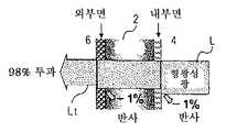
형광 물질로부터 방사된 형광성 광은, 도5에 도시된 바와 같이, 유리 등의 투명관(12)을 통과함에 따라 2개의 경계면, 즉, 내부 경계면(12a) 및 외부 경계면(12b)을 통과한다. 광이 각각의 경계면을 통과할 때, 총광량의 약 4%가 반사된다. 따라서, 투과된 광(Lt)의 광량은 투명관을 통과하기 전의 형광성 광의 광량의 약 92%로 감소된다. 형광 램프의 휘도를 상승시키기 위해, 부여된 전력을 증가시킴으로써 자외선의 강도를 향상시키려는 방법이 있다. 그러나, 이 방법은 전극의 열화 및 낮아진 발광 효율을 초래하기 때문에 권장할 만하지 않다. 저전력 소비 및 고휘도인 램프를 획득하기 위해서는 형광 물질로부터 방사된 형광성 광에 대하여 투과율을 상승시키는 것이 바람직하다. 수은으로부터 방사된 자외선에 의한 유리 등의 투명관의 열화를 억제하기 위해, 형광 물질층과 투명관의 내부면의 사이에 형성되는 산화 이트륨의 보호층이 램프에 제공되는 경우, 형광성 광에 대하여 더 낮은 투과율이 발생한다. 이러한 불편함을 고려하여, 투명관의 내부 경계면에서의 광의 반사는 미세 실리카 입자 등을 함유하는 저굴절제로 투명관의 내부 경계면을 피복하는 것에 의해 억제된다(특허 문서 1 내지 3). 그러나, 저굴절제를, 특히 투명관의 내부 경계면에 최적의 두께로 균일하게 도포하는 것이 곤란하다. 투명관의 외부 경계면만이 저굴절제로 도포되면, 투과율의 저감을 억제하는 현저한 효과는 나타나지 않으며, 따라서 사용되는 고가의 저굴절제에 의한 비용 상승 및 공정 단계 수의 증가에도 불구하고 매우 우수한 효과를 얻을 수 없다.Fluorescent light emitted from the fluorescent material passes through two boundaries, that is, the
반면에, 향상된 광선 방사 성능을 가지고 층 균열 등이 없는 형광 램프가 보고되어 있는데, 이 형광 램프는 주성분으로 주입자가 구형 또는 사실상 구형이며 40 내지 75 nm의 입경을 가지는 산화 이트륨과 산화 알루미늄을 포함하는 금속 산 화층 및 금속 산화층 상에 적층된 형광 물질층을 가지고 있다(특허 문서 4).On the other hand, fluorescent lamps have been reported that have improved light emission performance and no layer cracks, which include yttrium oxide and aluminum oxide, whose main components are spherical or substantially spherical and have a particle diameter of 40 to 75 nm. It has a fluorescent material layer laminated on the metal oxide layer and the metal oxide layer (Patent Document 4).
[특허 문서 1] 일본 특허 공개 공보 제2006-342023호[Patent Document 1] Japanese Patent Laid-Open No. 2006-342023
[특허 문서 2] 일본 특허 공개 공보 제2006-335881호[Patent Document 2] Japanese Patent Laid-Open No. 2006-335881
[특허 문서 3] 일본 특허 공개 공보 제2004-83307호[Patent Document 3] Japanese Patent Laid-Open No. 2004-83307
[특허 문서 4] 일본 특허 공개 공보 제2003-51284호[Patent Document 4] Japanese Patent Laid-Open No. 2003-51284
본 발명의 목적은 사용되는 재료의 종류의 개수 및 공정 단계수의 증가 없이, 전력절약을 실현하면서 형광물질로부터 방사된 형광성 광에 대하여 현저하게 향상된 투과율을 보여 고휘도를 달성하는 것이 가능한 형광 램프를 제공하는 것이다. 또 다른 목적은 전술된 형광 램프를 저비용으로 제조하는 방법이다.SUMMARY OF THE INVENTION An object of the present invention is to provide a fluorescent lamp capable of achieving high brightness by showing a markedly improved transmittance with respect to fluorescent light emitted from a fluorescent material while realizing power saving without increasing the number of types of materials used and the number of process steps. It is. Yet another object is a method of manufacturing the above-described fluorescent lamp at low cost.
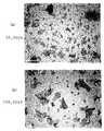
본 발명의 발명자들은 수은으로부터 방사된 자외선으로부터 형광 램프의 유리관 등의 투명관을 보호하기 위한 보호층에 이용된 산화 이트륨에 대한 집중연구를 하였다. 도6에 도시된 바와 같이, 종래의 형광 램프(11)는 자외선으로부터 투명관을 보호하기 위하여 투명관(12)과 형광 물질층(13) 사이에 형성되고 산화 이트륨(14a) 등을 이용하여 형성된 보호층(14)을 가지고 있다. 산화 이트륨의 입자는 구형 또는 사실상 구형이기 때문에, 형광 물질로부터 방사된 형광성 광은 산화 이트륨 입자의 표면에 의하여 분산된다. 이로 인해, 형광성 광에 대한 램프의 투과율이 낮아지는 경향이 있다. 보호층에서의 반사를 억제하기 위하여, 보호층(4)은 전자 현미경에 의해 출력되는 상을 도시하는 도1에 도시된 바와 같은 박편형 산화 이트륨 입자를 이용하여 형성된다. 구형 또는 사실상 구형인 산화 이트륨 입자를 이용하여 형성된 종래의 보호층이 제공됨으로써 초래되는 형광성 광 총량의 약 10%의 손실과 비교하면, 이 보호층을 제공하는 것은 형광성 광의 손실을 형광성 광 총량의 약 1%까지 감소시키는 것을 가능하게 한다는 것이 발견되었다. 본 발명은 이와 같은 발견 및 지식을 기초로 하여 이루어진다.The inventors of the present invention have concentrated research on yttrium oxide used in a protective layer for protecting transparent tubes such as glass tubes of fluorescent lamps from ultraviolet rays emitted from mercury. As shown in Fig. 6, the conventional
즉, 본 발명은 희가스 및 전기 방전에 의해 자외선을 생성하기 위한 수은이 캡슐화된 투명관과, 투명관의 2개의 단부 부분의 근처에 제공된 전극과, 투명관의 내부면에 걸쳐 형성된 형광 물질층을 포함하는 형광 램프에 관한 것이며, 투명관의 내부면과 형광 물질층 사이에 연장된 면 및 투명관의 외부면 중 적어도 한 면 상에 굴절률 조정층이 구비되고 상기 굴절률 조정층은 300 nm 이하의 평균 입경을 가지는 산화 이트륨을 함유한다.That is, the present invention provides a transparent tube encapsulated with mercury for generating ultraviolet rays by rare gas and electric discharge, an electrode provided near two end portions of the transparent tube, and a fluorescent material layer formed over the inner surface of the transparent tube. A fluorescent lamp comprising: a refractive index adjusting layer is provided on at least one of the surface extending between the inner surface of the transparent tube and the fluorescent material layer and the outer surface of the transparent tube, the refractive index adjusting layer is an average of 300 nm or less It contains yttrium oxide having a particle size.
또한, 본 발명은 희가스 및 전기 방전에 의해 자외선을 생성하기 위한 수은이 캡슐화된 투명관과, 투명관의 2개의 단부 부분의 근처에 제공된 전극과, 투명관의 내부면에 걸쳐 형성된 형광 물질층을 포함하는 형광 램프를 제조하는 방법에 관한 것이며, 300 nm 이하의 평균 입경을 가지는 박편형 산화 이트륨을 함유하는 분산부를 투명관의 내부면과 형광 물질층 사이에 연장된 면 및 투명관의 외부면 중 적어도 한 면에 도포하여 굴절률 조정층을 형성하는 공정을 포함한다.In addition, the present invention provides a transparent tube encapsulated with mercury for generating ultraviolet rays by rare gas and electric discharge, an electrode provided near two end portions of the transparent tube, and a fluorescent material layer formed over the inner surface of the transparent tube. A method of manufacturing a fluorescent lamp comprising: a dispersing portion containing flaky yttrium oxide having an average particle diameter of 300 nm or less, between the inner surface of the transparent tube and the outer surface of the transparent tube; It applies to at least one surface, and forms the refractive index adjustment layer.
본 발명에 따른 형광 램프는 사용되는 재료의 종류의 개수 및 공정 단계수의 증가 없이, 전력절약을 실현하면서 형광 물질로부터 방사된 형광성 광에 대하여 현저하게 향상된 투과율을 보여 고휘도를 달성하는 것이 가능하다.The fluorescent lamp according to the present invention can achieve high brightness by showing a markedly improved transmittance with respect to fluorescent light emitted from a fluorescent material while realizing power saving without increasing the number of types of materials used and the number of process steps.
본 발명에 따른 형광 램프 제조 방법은 이와 같은 형광 램프를 저비용으로 제조하는 것이 가능하다.The fluorescent lamp manufacturing method according to the present invention can produce such a fluorescent lamp at low cost.
본 발명에 따른 형광 램프는 희가스 및 전기 방전에 의해 자외선을 생성하기 위한 수은이 캡슐화된 투명관과, 투명관의 2개의 단부 부분의 근처에 제공된 전극과, 투명관의 내부면에 걸쳐 형성된 형광 물질층을 포함하고, 투명관의 내부면과 형광 물질층 사이에 연장된 면 및 투명관의 외부면 중 적어도 한 면 상에 굴절률 조정층이 구비되고, 굴절률 조정층은 300 nm 이하의 평균 입경을 가지는 산화 이트륨을 함유하는 것을 특징으로 한다.The fluorescent lamp according to the present invention is a transparent tube in which mercury is encapsulated for generating ultraviolet rays by rare gas and electric discharge, an electrode provided near two end portions of the transparent tube, and a fluorescent material formed over the inner surface of the transparent tube. And a refractive index adjusting layer on at least one of an outer surface of the transparent tube and a surface extending between the inner surface of the transparent tube and the fluorescent material layer, the refractive index adjusting layer having an average particle diameter of 300 nm or less. It is characterized by containing yttrium oxide.
본 발명의 형광 램프에 사용된 투명관은 유리와 같이 가시 광선을 투과시키는 임의의 물질로부터 형성될 수 있다. 투명관은 직선 형상, 만곡 형상, 환형 형상, 전구 형상 등을 포함하는 형상 중 임의의 형상을 가질 수 있다.The transparent tube used in the fluorescent lamp of the present invention may be formed from any material that transmits visible light, such as glass. The transparent tube may have any shape among shapes including straight shape, curved shape, annular shape, bulb shape and the like.
투명관은 자외선을 발생시키기 위한 수은을 아르곤 또는 네온 등의 희가스와 함께 캡슐화한다. 투명관 내에서 전기 방전에 의해 발생된 전자는 수은 원자와 충돌하여 수은 원자를 여기한다. 이와 같이 여기된 수은 원자는 253.7 nm의 파장의 자외선을 포함하는 자외선을 발생시킨다. 투명관 내에 캡슐화된 수은의 증기압은, 예를 들어, 형광 램프가 켜져 있는 동안 1 내지 10 Pa의 범위를 가진다.The transparent tube encapsulates mercury for generating ultraviolet rays with a rare gas such as argon or neon. The electrons generated by the electrical discharge in the transparent tube collide with the mercury atoms to excite the mercury atoms. The mercury atoms excited in this way generate ultraviolet rays including ultraviolet rays having a wavelength of 253.7 nm. The vapor pressure of the mercury encapsulated in the transparent tube, for example, ranges from 1 to 10 Pa while the fluorescent lamp is on.
투명관은 2개의 단부 부분 주변에 전기 방전을 일으켜 전술한 수은 원자가 자외선을 방사하도록 하는 한 쌍의 전극을 구비한다. 이러한 전극은 고온 전극일 수도 있고 저온 캐소드 타입 전극일 수도 있다. 이러한 고온 전극의 예로써, 각각 바륨, 칼슘, 이트륨 등의 산화물과 같은 이미터(emitter) 물질로 피막된 텅스텐 코일 등을 포함하는 고온 전극을 들 수 있다. 전압이 고온 전극에 걸쳐 인가되는 경우, 이미터는 희가스를 이온화하는 전자를 방사한다. 이렇게 이온화된 희가스의 이온은 전극과 충돌하여 글로우 방전을 일으킨다. 전술된 바와 같이, 방전에 의해 생성된 전자는 수은을 여기하여 수은이 자외선을 방사하게 한다. 저온 캐소드 타입 전극의 예로써, 각 전극이 니켈, 몰리브덴 등으로부터 성형되고 각각의 개구가 서로 대향되게 배치된 한 쌍의 컵 형상의 전극을 들 수 있다. 전압이 저온 캐소드 타입 전극에 걸쳐 인가되는 경우, 투명관 내에 소량으로 존재하는 전자는 희가스와 충돌하여 희가스를 이온화한다. 이렇게 이온화된 희가스의 이온은 전극과 충돌하여 전기 방전을 일으킨다. 방전에 의해 생성된 전자는 수은과 충돌하여 수은 원자를 여기하고, 그로 인해 수은 원자가 자외선을 방사하게 한다.The transparent tube has a pair of electrodes that cause an electrical discharge around the two end portions to cause the mercury atoms described above to emit ultraviolet light. Such an electrode may be a high temperature electrode or a low temperature cathode type electrode. Examples of such high temperature electrodes include high temperature electrodes each including a tungsten coil or the like coated with an emitter material such as an oxide such as barium, calcium, or yttrium. When a voltage is applied across the high temperature electrode, the emitter emits electrons which ionize the rare gas. The ions of the rarely ionized rare gas collide with the electrodes to cause glow discharge. As mentioned above, the electrons generated by the discharge excite mercury, causing the mercury to emit ultraviolet light. As an example of the low-temperature cathode type electrode, there may be mentioned a pair of cup-shaped electrodes in which each electrode is formed from nickel, molybdenum or the like and each opening is disposed to face each other. When a voltage is applied across the low temperature cathode type electrode, electrons present in a small amount in the transparent tube collide with the rare gas to ionize the rare gas. The ions of the rare gas ionized in this way collide with the electrode to cause an electrical discharge. Electrons generated by the discharge collide with mercury to excite mercury atoms, thereby causing the mercury atoms to emit ultraviolet light.
이와 같은 투명관의 내벽에 걸쳐 형성되는 형광 물질층은, 수은 원자로부터 방사되는 253.7 nm의 자외선에 의해 조사되는 경우 가시광선을 방사하는 형광 물질을 포함한다. 양호하게는, 형광 물질은 열에 의해 거의 열화되지 않고 열악한 수은 흡수성을 가진다. 어떤 경우, 높은 수은 증기압 조건이 형광 램프가 점등되어 있는 동안 얼마간 유지된다. 이러한 경우조차도, 바람직한 형광 물질은 형광 물질에 흡수되는 수은에 의해 야기되는 투명관의 열화를 억제할 수 있다. 이와 같은 형광 물질의 예로 Y2O3:Eu; YVO4:Eu; LaPO4:Ce,Tb; (Ba,Eu)MgAl10O17; (Ba,Sr,Eu)(Mg,Mn)Al10O17; Sr10(PO4)6C12: Eu; 및 (Sr,Ca,Ba,Mg)10(PO4)6C12: Eu를 포함한다. 형광 물질층은 수은으로부터 방사된 253.7 nm의 자외선에 의해 여기되는 경우의 녹색, 적색 및 청색의 범위 내의 각각의 가시광선을 방사하는 형광 물질을 포함하고, 그로 인해 색깔 표현에 우수한 백색광을 방사한다.The fluorescent material layer formed over the inner wall of such a transparent tube includes a fluorescent material that emits visible light when irradiated with 253.7 nm ultraviolet rays emitted from mercury atoms. Preferably, the fluorescent material is hardly degraded by heat and has poor mercury absorption. In some cases, high mercury vapor pressure conditions are maintained for some time while the fluorescent lamp is lit. Even in this case, the preferred fluorescent material can suppress the deterioration of the transparent tube caused by the mercury absorbed by the fluorescent material. Examples of such fluorescent material include Y2 O3 : Eu; YVO4 : Eu; LaPO4 : Ce, Tb; (Ba, Eu) MgAl10 O17 ; (Ba, Sr, Eu) (Mg, Mn) Al10 O17 ; Sr10 (PO4 )6 C12 : Eu; And (Sr, Ca, Ba, Mg)10 (PO4 )6 C12 : Eu. The fluorescent material layer includes a fluorescent material that emits each visible light in the range of green, red and blue when excited by 253.7 nm ultraviolet radiation emitted from mercury, thereby emitting white light excellent in color representation.
본 발명에 따른 형광 램프는 투명관의 내부면과 형광 물질층 사이에 연장된 면 및 투명관의 외부면 중 적어도 한 면에 구비되는 굴절률 조정층을 포함한다. 투명관의 내부면에 구비되는 굴절률 조정층은 형광 물질로부터 방사되는 가시 광선에 대한 투명관의 내부 공간의 굴절률보다는 높고 투명관의 굴절률보다는 낮은 굴절률을 가지며 투명관 경계면에서의 반사에 의한 형광성 광의 광량의 저하를 억제하는 기능을 한다. 투명관의 외부면에 구비되는 굴절률 조정층은 형광 물질로부터 방사되는 가시 광선에 대한 투명관의 굴절률보다는 낮고 대기의 굴절률보다는 높은 굴절률을 가지며 투명관 경계면에서의 반사에 의한 형광성 광의 광량의 저하를 억제하는 기능을 한다. 이러한 굴절률 조정층은 300 nm 이하의 평균 입경을 가지는 산화 이트륨을 함유한다. 산화 이트륨의 평균 입경은 양호하게는 20 내지 150 nm의 범위이고, 더 양호하게는 50 내지 100 nm의 범위이다. 300 nm 이하의 평균 입경을 가지는 산화 이트륨을 이용하여 형성된 굴절률 조정층을 구비함으로써 투명관의 경계면에 의해 반사되는 형광성 광량의 감소를 가능하게 한다. 산화 이트륨의 입자는 양호하게는 박판형이다. 박판형 산화 이트륨의 입경은 평면상의 조각의 돌 출 면적과 동일한 면적을 가지는 원의 직경에 대응하여 한정될 수 있다.The fluorescent lamp according to the present invention includes a refractive index adjusting layer provided on at least one of an outer surface of the transparent tube and a surface extending between the inner surface of the transparent tube and the fluorescent material layer. The refractive index adjusting layer provided on the inner surface of the transparent tube has a refractive index higher than the refractive index of the inner space of the transparent tube with respect to visible light emitted from the fluorescent material and lower than the refractive index of the transparent tube, and the amount of fluorescent light due to reflection at the boundary of the transparent tube It serves to suppress the deterioration. The refractive index adjusting layer provided on the outer surface of the transparent tube has a refractive index lower than that of the transparent tube with respect to visible light emitted from the fluorescent material and higher than the refractive index of the atmosphere, and suppresses a decrease in the amount of fluorescent light due to reflection at the boundary of the transparent tube. Function. This refractive index adjusting layer contains yttrium oxide having an average particle diameter of 300 nm or less. The average particle diameter of yttrium oxide is preferably in the range of 20 to 150 nm, more preferably in the range of 50 to 100 nm. By providing a refractive index adjusting layer formed using yttrium oxide having an average particle diameter of 300 nm or less, it is possible to reduce the amount of fluorescent light reflected by the interface of the transparent tube. The particles of yttrium oxide are preferably thin. The particle size of the thin yttrium oxide may be defined corresponding to the diameter of a circle having the same area as the protruding area of the flat piece.
여기에서, 레이저 회절 입자 크기 분포 분석기에 의해 측정된 산화 이트륨의 평균 입경치는 산화 이트륨의 입경으로 이용될 수 있다.Here, the average particle diameter of yttrium oxide measured by the laser diffraction particle size distribution analyzer can be used as the particle diameter of yttrium oxide.
이와 같은 굴절률 조정층을 형성하는데 있어서, 산화 이트륨은 분쇄되어 전술된 입경을 가진다. 산화 이트륨은 예를 들어, 제트 밀(jet mill), 볼 밀, 비드 밀 등의 방법으로 분쇄될 수 있다. 분쇄되는 산화 이트륨을 함유하는 분산부를 준비하는 단계, 투명관의 내부 또는 외부면에 이 분산부를 도포하는 단계 및 도포되는 분산부를 건조시키는 단계를 포함하는 방법을 채용하는 것이 가능하다. 산화 이트륨 분산에서 사용되는 특정한 분산매체의 예로써, 물과, 알콜, 부틸 아세테이트 및 자일렌 등의 유기 용매와, 그들의 혼합물을 들 수 있다. 분산부를 도포하는 방법은 피복, 침지, 스프레이 피복 등 중의 하나일 수 있다. 소정 두께를 가지도록 도포되는 분산의 피막을 건조시키는 방법의 예로써, 자연 건조, 가압건조 등을 들 수 있다. 가압 건조의 경우, 송풍 등의 속도 또는 온도가 너무 높으면 피막의 표면이 더 빨리 건조되고 피막 내부의 건조율이 낮아진다. 이는 가능한 균열 인자를 형성하는 피막의 표면 및 내부에 응력 작용을 야기한다. 이로 인해, 건조는 양호하게는, 예를 들어, 송풍의 온도 및 속도에 의해 제어된다.In forming such a refractive index adjusting layer, yttrium oxide is pulverized to have the aforementioned particle diameter. Yttrium oxide can be ground, for example, by a jet mill, ball mill, bead mill, or the like. It is possible to employ a method comprising the steps of preparing a dispersion containing yttrium oxide to be ground, applying the dispersion to the inner or outer surface of the transparent tube and drying the applied dispersion. Examples of specific dispersion media used in the yttrium oxide dispersion include water, organic solvents such as alcohols, butyl acetate and xylene, and mixtures thereof. The method of applying the dispersion may be one of coating, dipping, spray coating, and the like. As an example of the method of drying the dispersion | distribution film apply | coated so that it may have a predetermined thickness, natural drying, pressure drying, etc. are mentioned. In the case of pressure drying, if the speed or temperature of blowing or the like is too high, the surface of the film dries faster and the drying rate inside the film is lowered. This causes a stress action on the surface and inside of the film forming possible cracking factors. For this reason, drying is preferably controlled by the temperature and speed of blowing, for example.
양호하게는, 본 발명에 따른 형광 램프는 투명관의 내부면과 형광 물질층 사이에 연장된 면 및 투명관의 외부면 중 적어도 한 면에 형성되는 굴절률 조정층 및 다른 면에 형성되는 반사 억제층을 포함한다. 반사 억제층은 양호하게는 투명관보다 낮은 굴절률을 가진다. 이와 같은 반사 억제층을 형성하기 위한 물질의 예로 써, 실리카, 알루미나, 산화 이트륨, 지르코니아, 산화 마그네슘, 산화 티타늄, 산화 세륨 또는 불화 마그네슘으로부터 선택된 일종 또는 이종 이상의 산화 금속을 들 수 있다. 반사 억제층은 낮은 굴절률을 갖는 실리카 등의 중공 미세 입자를 함유할 수 있다. 이러한 중공 미세 입자의 예로써, 5 내지 100 nm 정도의 주 입경(primary particle diameter) 및 30 내지 90% 정도의 공극비를 가지는 중공 미세 입자를 들 수 있다. 반사 억제층의 두께는 예를 들어 300 내지 800 nm의 범위이다.Preferably, the fluorescent lamp according to the present invention is a refractive index adjusting layer formed on at least one of the surface extending between the inner surface of the transparent tube and the fluorescent material layer and the outer surface of the transparent tube and the reflection suppression layer formed on the other surface. It includes. The reflection suppression layer preferably has a lower refractive index than the transparent tube. Examples of the material for forming such a reflection suppression layer include one or more kinds of metal oxides selected from silica, alumina, yttrium oxide, zirconia, magnesium oxide, titanium oxide, cerium oxide or magnesium fluoride. The reflection suppression layer may contain hollow fine particles such as silica having a low refractive index. Examples of such hollow fine particles include hollow fine particles having a primary particle diameter of about 5 to 100 nm and a pore ratio of about 30 to 90%. The thickness of the reflection suppression layer is, for example, in the range of 300 to 800 nm.
전술된 물질은 반사 억제층을 형성하는데 있어서 적절하게 조합될 수 있다. 굴절률 조정층과 마찬가지로, 반사 억제층은 선택된 분말 형태의 혼합물을 사용하여 분산부를 준비하는 단계, 굴절률 조정층이 구비되어 있지 않은 투명관의 내부 또는 외부면에 분산부를 도포하는 단계 및 도포되는 분산부를 건조시키는 단계를 포함하는 방법에 의해 형성될 수 있다.The aforementioned materials may be appropriately combined in forming the reflection suppression layer. Like the refractive index adjusting layer, the reflection suppression layer may be prepared by using a mixture in the form of a selected powder, preparing a dispersion portion, applying the dispersion portion to the inner or outer surface of the transparent tube not provided with the refractive index adjustment layer, and the applied dispersion portion. It may be formed by a method comprising the step of drying.
본 발명의 형광 램프를 구동하는 조명 회로로써, 형광 램프로부터 개별적으로 구비되고 전극을 예열하고 고압 펄스를 생성하는 시동기 타입의 조명회로가 이용될 수 있다. 조명 회로로써, 형광 램프와 일체적으로 형성되고 전극 예열 회로 및 보조 회로를 포함하는 안정판을 함유하는 급시동 타입의 조명회로가 이용될 수 있다. 이러한 조명 회로와 일체화된 형광 램프는 만곡되거나 굴곡된 원주방향으로 글로브로 덮인 투명관 및 조명 회로에 연결되는 기저부를 포함하는 벌브 타입이거나 투명관을 외부로 노출하는 구조를 가진 타입일 수 있다.As a lighting circuit for driving the fluorescent lamp of the present invention, a starter type lighting circuit which is separately provided from the fluorescent lamp and preheats the electrode and generates a high voltage pulse can be used. As the lighting circuit, a quick start type lighting circuit which is integrally formed with the fluorescent lamp and contains a stabilizer plate including an electrode preheating circuit and an auxiliary circuit can be used. The fluorescent lamp integrated with the lighting circuit may be a bulb type including a curved or curved circumferential transparent tube covered with a globe and a base connected to the lighting circuit, or a type having a structure for exposing the transparent tube to the outside.
본 발명에 따른 형광 램프는 수은 원자로부터 방사되는 253.7 nm의 자외선에 의해 여기되는 가시광선을 방사하는 형광 물질 및 투명관의 경계면에서의 형광성 광의 반사를 억제하면서 가시 광선이 투명관을 통과하도록 하는 굴절률 조정층을 구비하여 램프의 휘도를 현저하게 향상시킨다.The fluorescent lamp according to the present invention has a refractive index that allows visible light to pass through a transparent tube while suppressing the reflection of fluorescent light at the interface of the fluorescent material and the transparent tube that emits visible light excited by 253.7 nm ultraviolet rays emitted from a mercury atom. The adjustment layer is provided to significantly improve the brightness of the lamp.
이러한 형광램프를 제조하는 방법에 따라 상기에 기재된 굴절률 조정층 및 반사 억제층이 투명관에 형성된다. 양호하게는, 형광물질이 용매에 분산되어 있는 분산부가 마련된 후 침지, 분무 등의 공정에 의해 굴절률 조정층 및 반사 억제층에 도포되어 소정의 두께를 가지는 피막을 형성한다. 그 이후에, 전극이 투명관의 단부 부분에 위치한 후 투명관은 관련 전극 등에 연결되는 각각의 외부 리드를 가지는 기저부로 밀봉된다. 이러한 방시으로, 형광 램프를 제조할 수 있다.According to the method of manufacturing such a fluorescent lamp, the refractive index adjusting layer and the reflection suppression layer described above are formed in the transparent tube. Preferably, after the dispersion portion in which the fluorescent substance is dispersed in the solvent is provided, it is applied to the refractive index adjusting layer and the reflection suppression layer by a process such as dipping and spraying to form a film having a predetermined thickness. Thereafter, after the electrode is positioned at the end portion of the transparent tube, the transparent tube is sealed with a base having respective outer leads connected to the related electrode or the like. With this method, a fluorescent lamp can be manufactured.
이하에, 본발명은 본 발명의 기술적인 범주를 전혀 제한하지 않는 실시예를 통하여 더욱 자세하게 기재될 것이다.In the following, the present invention will be described in more detail by way of examples which do not limit the technical scope of the invention at all.
[제1 실시예][First Embodiment]
박편형 산화 이트륨이 이소프로필 알콜에 첨가되어 5 질량% 분산부를 마련하였다. 400 nm의 두께를 가지는 굴절률 조정층이 분산과 함께 스핀 피복 소다 유리에 의해 형성되어 건조에 이어 30초 동안 150 rpm으로 마련되어 제2 샘플을 제공하였다.Flaky yttrium oxide was added to the isopropyl alcohol to provide a 5 mass% dispersion. A refractive index adjusting layer with a thickness of 400 nm was formed by spin coated soda glass with dispersion to provide a second sample at 150 rpm for 30 seconds following drying.
10 내지 20 nm의 입경을 가지는 저굴절 실리카 입자를 에탄올에 첨가하여 분산부를 마련하였다. 100 nm의 두께를 가지는 반사 억제층이 분산부와 함께 스핀 피복 소다 유리에 의해 형성되어 건조에 이어 마련되어 제1 샘플을 제공하였다.Low refractive silica particles having a particle diameter of 10 to 20 nm were added to ethanol to prepare a dispersion portion. An antireflection layer having a thickness of 100 nm was formed by spin-coated soda glass together with the dispersion, followed by drying to provide a first sample.
또한, 제2 샘플과 동일한 굴절률 조정층 및 제1 샘플과 동일한 반사 억제층이 소다 유리의 대향 측면에 형성되어 제3 샘플을 제공하였다.In addition, the same refractive index adjusting layer as the second sample and the same reflection suppression layer as the first sample were formed on opposite sides of the soda glass to provide a third sample.
이렇게 얻어진 제1 내지 제3 샘플 및 비교예인 소다 유리(G)는 그들 각각의 투과율에 대하여 분광광도계 UV-2300PC[제조원: 시마드즈 코포레이션(Shimadzu Corporation)]를 이용하여 측정되었다. 그 결과는 도2에 도시되었다.The first to third samples thus obtained and the soda glass (G) as comparative examples were measured using a spectrophotometer UV-2300PC (manufactured by Shimadzu Corporation) for their respective transmittances. The result is shown in FIG.
[제2 실시예]Second Embodiment
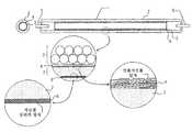
본 발명의 형광 램프가 적용되는 저온 캐소드 형광 램프의 일 예가 도3에 도시되었다. 전술한 굴절률 조정층(4) 및 형광 물질층(3)이 두께 0.5 mm를 가지는 붕규산 유리인 투명관(2)의 내부면에 순차적으로 형성되는 동시에, 반사 억제층(6)은 투명관의 외부면에 형성된다다. 형광 물질층(3)의 두께는 20 μm이다. 니켈의 전극(5)은 각각 투명관의 대향 단부의 각각에 위치하고 투명관의 대향 단부는 도시되어 있지 않은 밀봉 부재에 의해 밀봉된다. 수은은 투명관 내에서 캡슐화되어 램프가 점등되어 있는 동안 1 내지 10 Pa의 증기압을 가지는 동시에, 투명관 내에서 캡슐화된 아르곤 등의 희가스는 50 Torr 정도의 압력을 가진다.An example of a low temperature cathode fluorescent lamp to which the fluorescent lamp of the present invention is applied is shown in FIG. The above-described refractive
굴절률 조정층(4)는 아래의 방법에 의해 형성된다. 박편형 산화 이트륨을 이소프로필 알콜에 첨가하여 3 질량% 분산부를 마련한다. 송풍 건조에 이어, 유리관의 내부면을 마련되는 분산부에 침지하여 400 nm의 두께를 가지는 굴절률 조정층을 형성한다.The refractive
반사 억제층(6)은 아래의 방법에 의해 형성된다. 10 내지 20 nm의 평균 입경을 가지는 중공 실리카 입자를 에탄올에 첨가하여 분산부를 마련한다. 100 nm의 두께를 가지는 굴절 억제층이 침지에 의해 투명관의 외부면에 형성된다.The
비교예로써, 굴절률 조정층(4) 및 반사 억제층(6)이 구비되지 않은 점을 제외하고는 상기에 기재된 바와 같은 방식으로 제조한다.As a comparative example, it is produced in the same manner as described above except that the refractive
이렇게 얻어진 형광 램프는 취도 노출계(품명: SR3, 제조원: 톱콘 코포레이션)에 의해 투명관으로부터 나오는 투과된 광선의 휘도에 대하여 각각 측정된다. 실시예의 형광 램프의 휘도는 비교예의 형광램프의 휘도보다 약 6% 높다. 실시예의 형광 램프를 통과하는 형광성 광은 도4에 도시되어 있다.The fluorescent lamp thus obtained is measured with respect to the luminance of the light transmitted through the transparent tube by a light exposure meter (trade name: SR3, manufactured by Topcon Corporation). The luminance of the fluorescent lamp of the example is about 6% higher than the luminance of the fluorescent lamp of the comparative example. Fluorescent light passing through the fluorescent lamp of the embodiment is shown in FIG.
본 발명에 따른 형광 램프는 고온 전극 또는 저온 전극을 가지는 형광 램프에 유용하게 적용될 수 있다. 또한 형광 램프는 전력 소비를 증가시키지 않고 향상된 휘도를 나타낼 수 있고 저비용으로 제조될 수 있다.The fluorescent lamp according to the present invention can be usefully applied to a fluorescent lamp having a high temperature electrode or a low temperature electrode. In addition, fluorescent lamps can exhibit improved brightness and can be manufactured at low cost without increasing power consumption.
도1은 본 발명에 따른 형광 램프에 사용하기 위한 산화 이트륨의 전자 현미경 사진을 도시하는 도면.1 shows an electron micrograph of yttrium oxide for use in a fluorescent lamp according to the present invention.
도2는 본 발명에 따른 형광 램프에서 굴절률 조정층 및 반사 억제층의 투과율을 도시하는 그래프.2 is a graph showing the transmittances of the refractive index adjusting layer and the reflection suppression layer in the fluorescent lamp according to the present invention;
도3은 본 발명에 따른 형광 램프의 일 예로 직선관 형광 램프의 구조를 개략적으로 도시하는 도면.3 is a view schematically showing the structure of a straight tube fluorescent lamp as an example of a fluorescent lamp according to the present invention;
도4는 본 발명에 따른 형광 램프의 일 예의 투과된 형광성 광을 도시하는 단면도.4 is a sectional view showing transmitted fluorescent light of an example of a fluorescent lamp according to the present invention;
도5는 형광성 광에 대한 종래의 형광 램프의 투과율을 도시하는 단면도.Fig. 5 is a sectional view showing the transmittance of a conventional fluorescent lamp with respect to fluorescent light.
도6은 종래의 형광 램프의 구조를 개략적으로 도시하는 도면.Fig. 6 is a diagram schematically showing the structure of a conventional fluorescent lamp.
<도면의 주요 부분에 대한 부호의 설명><Explanation of symbols for the main parts of the drawings>
3: 형광 물질층3: fluorescent material layer
4: 굴절률 조정층4: refractive index adjusting layer
5: 전극5: electrode
6: 반사 억제층6: antireflection layer
11: 형광 램프11: fluorescent lamp
12: 투명관12: transparent tube
13: 형광 물질층13: fluorescent material layer
14: 보호층14: protective layer
Claims (7)
Translated fromKoreanApplications Claiming Priority (2)
| Application Number | Priority Date | Filing Date | Title |
|---|---|---|---|
| JP2007077560AJP4472716B2 (en) | 2007-03-23 | 2007-03-23 | Fluorescent lamp and manufacturing method thereof |
| JPJP-P-2007-00077560 | 2007-03-23 |
Publications (2)
| Publication Number | Publication Date |
|---|---|
| KR20080086841A KR20080086841A (en) | 2008-09-26 |
| KR100944287B1true KR100944287B1 (en) | 2010-02-24 |
Family
ID=39914489
Family Applications (1)
| Application Number | Title | Priority Date | Filing Date |
|---|---|---|---|
| KR1020080026360AExpired - Fee RelatedKR100944287B1 (en) | 2007-03-23 | 2008-03-21 | Fluorescent Lamp and Manufacturing Method Thereof |
Country Status (4)
| Country | Link |
|---|---|
| JP (1) | JP4472716B2 (en) |
| KR (1) | KR100944287B1 (en) |
| CN (1) | CN101271823A (en) |
| TW (1) | TW200847221A (en) |
Families Citing this family (2)
| Publication number | Priority date | Publication date | Assignee | Title |
|---|---|---|---|---|
| JP2010123542A (en)* | 2008-11-21 | 2010-06-03 | Toshiba Lighting & Technology Corp | Liquid agent for coating diffusion film of high-pressure discharge lamp and high-pressure discharge lamp |
| JP6138588B2 (en)* | 2013-05-27 | 2017-05-31 | マイクロ波化学株式会社 | Method for producing rare earth oxide fine particles |
Citations (2)
| Publication number | Priority date | Publication date | Assignee | Title |
|---|---|---|---|---|
| KR19990083535A (en)* | 1998-04-28 | 1999-11-25 | 모리 가즈히로 | A fluorescent lamp and a method for manufacturing the same |
| JP2000111911A (en)* | 1998-10-09 | 2000-04-21 | Hitachi Ltd | Lamp and liquid crystal display |
- 2007
- 2007-03-23JPJP2007077560Apatent/JP4472716B2/ennot_activeExpired - Fee Related
- 2008
- 2008-03-21TWTW097110109Apatent/TW200847221A/enunknown
- 2008-03-21KRKR1020080026360Apatent/KR100944287B1/ennot_activeExpired - Fee Related
- 2008-03-24CNCNA2008100872527Apatent/CN101271823A/enactivePending
Patent Citations (2)
| Publication number | Priority date | Publication date | Assignee | Title |
|---|---|---|---|---|
| KR19990083535A (en)* | 1998-04-28 | 1999-11-25 | 모리 가즈히로 | A fluorescent lamp and a method for manufacturing the same |
| JP2000111911A (en)* | 1998-10-09 | 2000-04-21 | Hitachi Ltd | Lamp and liquid crystal display |
Also Published As
| Publication number | Publication date |
|---|---|
| JP2008243371A (en) | 2008-10-09 |
| CN101271823A (en) | 2008-09-24 |
| KR20080086841A (en) | 2008-09-26 |
| TW200847221A (en) | 2008-12-01 |
| JP4472716B2 (en) | 2010-06-02 |
Similar Documents
| Publication | Publication Date | Title |
|---|---|---|
| KR0145631B1 (en) | Luminescent material for mercury discharge lamp including phosphor and a continuous protective layer | |
| JP4095019B2 (en) | Low pressure gas discharge lamp with mercury-free filling gas | |
| US6906475B2 (en) | Fluorescent lamp and high intensity discharge lamp with improved luminous efficiency | |
| JP5137391B2 (en) | Dielectric barrier discharge lamp | |
| US4940918A (en) | Fluorescent lamp for liquid crystal backlighting | |
| KR100944287B1 (en) | Fluorescent Lamp and Manufacturing Method Thereof | |
| WO2012026247A1 (en) | Fluorescent lamp | |
| CN201266596Y (en) | High color rendering lamp | |
| JP5515141B2 (en) | Phosphor and fluorescent lamp | |
| KR20060044680A (en) | Fluorescent lamps for visible light emission | |
| JP2008123817A (en) | Fluorescent lamp, and manufacturing method of fluorescent lamp | |
| JP5213027B2 (en) | Fluorescent lamp | |
| JP2000067813A (en) | Fluorescent lamp and light source using it | |
| JP5515142B2 (en) | Phosphor and fluorescent lamp | |
| JP2008277015A (en) | Fluorescent lamp | |
| JP2006511040A (en) | Impurity getter of UV reflection base coat in fluorescent lamp | |
| TWI389164B (en) | External electrode fluorescent lamp and apparatus utilizing the same | |
| US20040135486A1 (en) | Highly loaded fluorescent lamp | |
| JPH11265685A (en) | Fluorescent lamp | |
| US20100008060A1 (en) | Light assembly with high color-rendering property | |
| KR100731154B1 (en) | Xenon electrodeless fluorescent lamps | |
| KR930003837B1 (en) | Hot cathode type low pressure rare gas discharge fluorescent lamp | |
| JPH09199085A (en) | Fluorescent lamp and lighting device using the same | |
| JP2005011632A (en) | Cold cathode fluorescent lamp | |
| JP2000133204A (en) | Fluorescent lamp and light source device |
Legal Events
| Date | Code | Title | Description |
|---|---|---|---|
| A201 | Request for examination | ||
| PA0109 | Patent application | St.27 status event code:A-0-1-A10-A12-nap-PA0109 | |
| PA0201 | Request for examination | St.27 status event code:A-1-2-D10-D11-exm-PA0201 | |
| P11-X000 | Amendment of application requested | St.27 status event code:A-2-2-P10-P11-nap-X000 | |
| P13-X000 | Application amended | St.27 status event code:A-2-2-P10-P13-nap-X000 | |
| PG1501 | Laying open of application | St.27 status event code:A-1-1-Q10-Q12-nap-PG1501 | |
| D13-X000 | Search requested | St.27 status event code:A-1-2-D10-D13-srh-X000 | |
| D14-X000 | Search report completed | St.27 status event code:A-1-2-D10-D14-srh-X000 | |
| E902 | Notification of reason for refusal | ||
| PE0902 | Notice of grounds for rejection | St.27 status event code:A-1-2-D10-D21-exm-PE0902 | |
| E13-X000 | Pre-grant limitation requested | St.27 status event code:A-2-3-E10-E13-lim-X000 | |
| P11-X000 | Amendment of application requested | St.27 status event code:A-2-2-P10-P11-nap-X000 | |
| P13-X000 | Application amended | St.27 status event code:A-2-2-P10-P13-nap-X000 | |
| E701 | Decision to grant or registration of patent right | ||
| PE0701 | Decision of registration | St.27 status event code:A-1-2-D10-D22-exm-PE0701 | |
| GRNT | Written decision to grant | ||
| PR0701 | Registration of establishment | St.27 status event code:A-2-4-F10-F11-exm-PR0701 | |
| PR1002 | Payment of registration fee | St.27 status event code:A-2-2-U10-U11-oth-PR1002 Fee payment year number:1 | |
| PG1601 | Publication of registration | St.27 status event code:A-4-4-Q10-Q13-nap-PG1601 | |
| R18-X000 | Changes to party contact information recorded | St.27 status event code:A-5-5-R10-R18-oth-X000 | |
| FPAY | Annual fee payment | Payment date:20130118 Year of fee payment:4 | |
| PR1001 | Payment of annual fee | St.27 status event code:A-4-4-U10-U11-oth-PR1001 Fee payment year number:4 | |
| LAPS | Lapse due to unpaid annual fee | ||
| PC1903 | Unpaid annual fee | St.27 status event code:A-4-4-U10-U13-oth-PC1903 Not in force date:20140219 Payment event data comment text:Termination Category : DEFAULT_OF_REGISTRATION_FEE | |
| PC1903 | Unpaid annual fee | St.27 status event code:N-4-6-H10-H13-oth-PC1903 Ip right cessation event data comment text:Termination Category : DEFAULT_OF_REGISTRATION_FEE Not in force date:20140219 | |
| P22-X000 | Classification modified | St.27 status event code:A-4-4-P10-P22-nap-X000 |