KR100943621B1 - Power control device and method in communication system - Google Patents
Power control device and method in communication systemDownload PDFInfo
- Publication number
- KR100943621B1 KR100943621B1KR1020060125733AKR20060125733AKR100943621B1KR 100943621 B1KR100943621 B1KR 100943621B1KR 1020060125733 AKR1020060125733 AKR 1020060125733AKR 20060125733 AKR20060125733 AKR 20060125733AKR 100943621 B1KR100943621 B1KR 100943621B1
- Authority
- KR
- South Korea
- Prior art keywords
- power
- state
- user terminal
- active
- module
- Prior art date
- Legal status (The legal status is an assumption and is not a legal conclusion. Google has not performed a legal analysis and makes no representation as to the accuracy of the status listed.)
- Expired - Fee Related
Links
Images


Classifications
- G—PHYSICS
- G06—COMPUTING OR CALCULATING; COUNTING
- G06F—ELECTRIC DIGITAL DATA PROCESSING
- G06F1/00—Details not covered by groups G06F3/00 - G06F13/00 and G06F21/00
- G06F1/26—Power supply means, e.g. regulation thereof
- G06F1/32—Means for saving power
- G06F1/3203—Power management, i.e. event-based initiation of a power-saving mode
- G06F1/3206—Monitoring of events, devices or parameters that trigger a change in power modality
- G06F1/3209—Monitoring remote activity, e.g. over telephone lines or network connections
- H—ELECTRICITY
- H04—ELECTRIC COMMUNICATION TECHNIQUE
- H04L—TRANSMISSION OF DIGITAL INFORMATION, e.g. TELEGRAPHIC COMMUNICATION
- H04L12/00—Data switching networks
- H04L12/02—Details
- H04L12/10—Current supply arrangements
- H—ELECTRICITY
- H04—ELECTRIC COMMUNICATION TECHNIQUE
- H04W—WIRELESS COMMUNICATION NETWORKS
- H04W52/00—Power management, e.g. Transmission Power Control [TPC] or power classes
- H04W52/02—Power saving arrangements
- H04W52/0209—Power saving arrangements in terminal devices
- Y—GENERAL TAGGING OF NEW TECHNOLOGICAL DEVELOPMENTS; GENERAL TAGGING OF CROSS-SECTIONAL TECHNOLOGIES SPANNING OVER SEVERAL SECTIONS OF THE IPC; TECHNICAL SUBJECTS COVERED BY FORMER USPC CROSS-REFERENCE ART COLLECTIONS [XRACs] AND DIGESTS
- Y02—TECHNOLOGIES OR APPLICATIONS FOR MITIGATION OR ADAPTATION AGAINST CLIMATE CHANGE
- Y02D—CLIMATE CHANGE MITIGATION TECHNOLOGIES IN INFORMATION AND COMMUNICATION TECHNOLOGIES [ICT], I.E. INFORMATION AND COMMUNICATION TECHNOLOGIES AIMING AT THE REDUCTION OF THEIR OWN ENERGY USE
- Y02D30/00—Reducing energy consumption in communication networks
- Y02D30/70—Reducing energy consumption in communication networks in wireless communication networks
Landscapes
- Engineering & Computer Science (AREA)
- Theoretical Computer Science (AREA)
- Computer Networks & Wireless Communication (AREA)
- Signal Processing (AREA)
- Physics & Mathematics (AREA)
- General Engineering & Computer Science (AREA)
- General Physics & Mathematics (AREA)
- Telephone Function (AREA)
- Mobile Radio Communication Systems (AREA)
Abstract
Translated fromKoreanDescription
Translated fromKorean도 1은 광대역 무선 접속 통신 시스템의 통신망 구조를 개략적으로 도시한 도면1 is a diagram schematically showing a network structure of a broadband wireless access communication system
도 2는 본 발명의 실시예에 따른 사용자 단말의 구조를 개략적으로 도시한 도면2 is a view schematically showing the structure of a user terminal according to an embodiment of the present invention;
도 3은 본 발명의 실시예에 따른 사용자 단말이 지원하는 전력 상태를 개략적으로 도시한 도면3 is a diagram schematically showing a power state supported by a user terminal according to an embodiment of the present invention;
도 4는 사용자 단말이 파워-온 상태에서 파워-오프 상태 또는 파워-액티브-세이브 상태로 상태 천이하는 과정을 도시한 순서도4 is a flowchart illustrating a process of a state in which a user terminal transitions from a power-on state to a power-off state or a power-active-save state.
도 5는 사용자 단말이 파워-액티브-세이브 상태에서 파워-오프 상태 또는 파워-온 상태로 천이하는 과정을 도시한 순서도5 is a flowchart illustrating a process of a user terminal transitioning from a power-active-save state to a power-off state or a power-on state
도 6은 본 발명의 제 1 실시예에 따른 파워-액티브-세이브 상태인 사용자 단말이 파워-온 상태로 천이할 경우의 동작을 도시한 도면6 is a diagram illustrating an operation when a user terminal in a power-active-save state transitions to a power-on state according to the first embodiment of the present invention.
도 7은 본 발명의 제 2 실시예에 따른 파워-액티브-세이브 상태인 사용자 단말이 파워-온 상태로 천이할 경우의 동작을 도시한 도면FIG. 7 illustrates an operation when a user terminal in a power-active-save state transitions to a power-on state according to the second embodiment of the present invention.
본 발명은 통신 시스템의 전력 제어 장치 및 방법에 관한 것이다.The present invention relates to a power control apparatus and method for a communication system.
차세대 통신 시스템인 4세대(4G: 4th Generation, 이하 '4G' 라 칭하기로 한다) 통신 시스템에서는 이동성(mobility)과 다양한 서비스 품질(QoS: Quality of Service, 이하 'QoS' 라 칭하기로 한다)을 보장하는 형태로 고속 서비스를 지원하도록 하는 연구가 활발히 진행되고 있다.The 4th generation (hereinafter referred to as 4G) communication system, which is the next generation communication system, guarantees mobility and various quality of service (QoS). In order to support high-speed services, researches are being actively conducted.
도 1은 차세대 통신 시스템, 일예로 광대역 무선 접속(BWA: Broadband Wireless Access, 이하 'BWA' 라 칭하기로 한다) 통신 시스템의 구조를 개략적으로 도시한 도면이다.FIG. 1 is a diagram schematically illustrating a structure of a next generation communication system, for example, a broadband wireless access (BWA) communication system.
도 1을 참조하면, BWA 통신 시스템은 사용자 단말(101), 중계국(RAS: Radio Access Station, 이하 'RAS' 라 칭하기로 한다)(103), 제어국(ACR: Access Control Router, 이하 'ACR' 이라 칭하기로 한다)(107), 그 밖에 상기 ACR(107)로 통신 서비스를 제공하는 서버들을 포함한다.Referring to FIG. 1, the BWA communication system includes a
상기 사용자 단말(101), 일예로 노트북, 개인 휴대 정보 단말기(PDA: Personal Digital Assistance), 휴대전화, 휴대형 멀티미디어 재생기(PMP: Portable Multimedia Player), 디지털 카메라 등은 상기 BWA 통신 시스템에 접속하여 통신 서비스를 제공 받는다.The
상기 RAS(103)는 상기 사용자 단말(101)과 데이터를 송수신하고 인터넷 프로 토콜(IP: Internet Protocol, 이하 'IP'라 칭하기로 한다) 네트워크(Network)(105)를 통해 상기 ACR(107)과 IP 연결된다. 또한 상기 RAS(103)는 통신 시스템에 접속하는 사용자 단말(101)과의 무선 접속 규격 처리 동작을 수행하며, 상기 사용자 단말(101)과 데이터를 송수신하기 위한 스케쥴링 및 레인징(ranging) 동작을 수행한다. 상기 RAS(103)는 자신으로부터 통신 서비스를 제공받을 수 있는 셀의 초기화 및 통신 시스템 정보를 사용자 단말(101)로 전송하며, 상기 사용자 단말(101)이 셀 내의 섹터들 간을 이동할 경우 상기 사용자 단말(101)의 섹터간 핸드오버(Handover)를 제어한다.The RAS 103 transmits and receives data to and from the
상기 ACR(107)은 IP 연결된 상기 RAS(103)를 제어하는 기능을 수행하며, 하나의 ACR(107)이 다수의 RAS들을 제어할 수도 있다. 또한 상기 ACR(107)은 통신 서비스를 제공하는 서버들, 일예로 비디오 및 오디오 서비스를 제공하는 VoD/AoD 서버(111), 인터넷 웹(Web) 서비스를 제공하는 웹 서버(113). 음성 및 화상 서비스를 제공하는 VoIP/VT 서버(115), 인스턴트 메시징(IM: Instant Messaging, 이하 'IM'이라 칭하기로 한다) 서비스를 제공하는 메신져(Messenger) 서버(117)가 제공하는 통신 서비스를 RAS(103)로 전송함으로써 통신 시스템에 접속한 사용자 단말(101)로 통신 서비스를 제공하도록 한다. 그리고 상기 ACR(107)은 이를 위해 통신 시스템에 접속하는 상기 사용자 단말(101)에 대한 인증, IP 주소 할당 및 라우팅 등의 기능을 수행한다.The ACR 107 performs a function of controlling the
또한 상기 IP 네트워크(105, 109)는 RAS(103)와 ACR(107) 및 통신 서비스를 제공하는 서버들, 즉 VoD/AoD 서버(111), 웹 서버(113), VoIP/VT 서버(115), 메신 저 서버(117)와 인터페이스를 처리하여 네트워크를 형성한다.In addition, the
한편, BWA 통신 시스템에서 사용자 단말(101)은 파워-온(Power-ON) 상태, 파워-오프(Power-OFF) 상태, 파워-세이브(Power-SAVE) 상태를 지원한다. 여기서, 상기 파워-온 상태는 상기 사용자 단말(101)이 포함하는 모든 모듈들에 전력이 공급되는 상태를 나타낸다. 상기 파워-온 상태인 사용자 단말(101)은 사용자가 상기 사용자 단말(101)의 전력 관련 버튼을 직접 누르거나 미리 설정된 시간 내에 데이터 송수신이 더 이상 존재하지 않음을 검출하면, 파워-오프 상태로 상태 천이한다. 여기서, 상기 파워-오프 상태는 상기 사용자 단말(101)이 포함하는 모든 모듈들의 전력 공급을 중단하는 상태를 나타낸다. 또한 상기 파워-온 상태의 사용자 단말(101)은 파워-세이브 상태로 상태 천이할 수 있는데, 이러한 파워-세이브 상태에 따른 동작으로 상기 사용자 단말(101)의 제한적 배터리 용량에 따른 문제를 해결할 수 있다.Meanwhile, in the BWA communication system, the
하지만 상기 사용자 단말(101)은 일단 파워-세이브 상태가 되거나 파워-오프 상태가 되면, 파워-온 상태로 상태 천이하기 전에는 통신 서비스를 제공받을 수 없다. 즉, 파워-세이브 상태 혹은 파워-오프 상태에서는 사용자 단말의 배터리 용량을 아낄 수는 있으나 해당 사용자 단말에 서비스를 요청하거나 데이터를 송신할 수 없는 문제점이 있었다.However, once the
따라서, 본 발명의 목적은 전력 제어 방법 및 장치를 제공함에 있다.Accordingly, an object of the present invention is to provide a power control method and apparatus.
상기한 목적을 달성하기 위한 본 발명의 방법은; 통신 시스템에서 사용자 단말의 전력 제어 방법에 있어서, 파워-온(Power-ON) 상태에서 파워-액티브-세이브(Power-Active-SAVE) 상태로 천이를 발생시키는 제 1이벤트가 발생함을 검출하면, 상기 파워-온 상태에서 파워-액티브-세이브 상태로 천이하는 과정과, 상기 파워-액티브-세이브 상태에서 사용자 단말이 포함하는 모듈들 중 제어 모듈과 송신 모듈과 수신 모듈에 제한적인 전력이 공급되도록 제어하는 과정을 포함하고, 상기 제한적인 전력은 상기 통신 시스템으로부터 수신되는 메시지를 해독하는 데에 필요한 최소 전력임을 특징으로 한다.The method of the present invention for achieving the above object; In the method for controlling power of a user terminal in a communication system, if it is detected that a first event occurs that causes a transition from a power-on state to a power-active-save state, Transitioning from the power-on state to a power-active-save state, and controlling power such that limited power is supplied to a control module, a transmission module, and a receiving module among the modules included in the user terminal in the power-active-save state; And the limited power is the minimum power required to decrypt a message received from the communication system.
상기한 목적을 달성하기 위한 본 발명의 장치는; 신호를 송신하는 송신 모듈과, 신호를 수신하는 수신 모듈과, 소정 제어에 따라 사용자 단말이 포함하는 모듈들에 대한 전력 공급을 수행하는 전력 공급 모듈과, 파워-온 상태에서 파워-액티브-세이브 상태로 천이를 발생시키는 제 1이벤트가 발생함을 검출하면, 상기 파워-온 상태에서 파워-액티브-세이브 상태로 천이하도록 제어하고, 상기 파워-액티브-세이브 상태에서 사용자 단말이 포함하는 모듈들 중 제어 모듈과 상기 송신 모듈과 상기 수신 모듈에 제한적인 전력이 공급되도록 상기 전력 공급 모듈의 동작을 제어하는 상기 제어 모듈을 포함하고, 상기 제한적인 전력은 상기 통신 시스템으로부터 수신되는 메시지를 해독하는 데에 필요한 최소 전력임을 특징으로 한다.The apparatus of the present invention for achieving the above object; A transmission module for transmitting a signal, a receiving module for receiving a signal, a power supply module for supplying power to modules included in a user terminal according to a predetermined control, and a power-active-save state in a power-on state When it is detected that the first event that causes the transition to occur, the control to transition from the power-on state to the power-active-save state, the control of the modules included in the user terminal in the power-active-save state And a control module for controlling the operation of the power supply module such that a limited power is supplied to the transmitting module and the receiving module, wherein the limited power is required to decrypt a message received from the communication system. Characterized in that the minimum power.
이하, 본 발명에 따른 바람직한 실시예를 첨부한 도면을 참조하여 상세히 설명한다. 하기의 설명에서는 본 발명의 동작을 이해하는데 필요한 부분만을 설명하며 그 이외의 배경 기술은 본 발명의 요지를 흩트리지 않도록 생략한다.Hereinafter, exemplary embodiments of the present invention will be described in detail with reference to the accompanying drawings. In the following description, only parts necessary for understanding the operation of the present invention will be described, and other background art will be omitted so as not to distract from the gist of the present invention.
본 발명은 통신 시스템, 일 예로 광대역 무선 접속(BWA: Broadband Wireless Access, 이하 'BWA'라 칭하기로 한다) 통신 시스템에서 전력 제어 장치 및 방법을 제안한다. 또한, 본 발명의 통신 시스템 구조는 도 1에서 설명한 통신 시스템의 구조와 동일하므로, 여기서는 그 상세한 설명을 생략하기로 한다. 그러면 여기서 도 2를 참조하여 본 발명의 실시예에 따른 사용자 단말의 구조에 대해서 설명하기로 한다.The present invention proposes a power control apparatus and method in a communication system, for example, a broadband wireless access (BWA) communication system. In addition, since the structure of the communication system of the present invention is the same as that of the communication system described with reference to FIG. 1, detailed description thereof will be omitted here. Next, a structure of a user terminal according to an exemplary embodiment of the present invention will be described with reference to FIG. 2.
도 2는 본 발명의 실시예에 따른 사용자 단말의 구조를 개략적으로 도시한 도면이다.2 is a view schematically showing the structure of a user terminal according to an embodiment of the present invention.
상기 도 2를 참조하면, 상기 사용자 단말은 전력 공급 모듈(Power Supply Module)(201), 디스플레이 모듈(Display Module)(203), 음성 모듈(Audio Module)(205), 저장 모듈(Disk Module)(207), 제어 모듈(Main Controller Processor Module)(209), 송신 모듈(Wireless Communication Transmitter Module)(211), 수신 모듈(Wireless Communication receiver Module)(213)을 포함한다.Referring to FIG. 2, the user terminal includes a
상기 전력 공급 모듈(201)은 각 모듈들의 전력을 공급하는 역할을 한다. 상기 제어 모듈(209)은 각 모듈들의 동작을 제어한다. 상기 디스플레이 모듈(203)은 상기 제어 모듈의 제어에 따라 데이터를 디스플레이하고, 음성 모듈(205)은 상기 제어 모듈(209)의 제어에 따라 음성 데이터를 출력한다. 저장 모듈(207)은 상기 사용자 단말에서 발생하는 데이터들을 저장한다. 상기 송신 모듈(211)은 데이터 송신 기능을 제공하고, 상기 수신 모듈(213)은 데이터 수신 기능을 제공한다. 그러면 여기서 도 3을 참조하여 본 발명의 실시예에 따른 사용자 단말이 지원하는 전력 상태 에 대하여 설명하기로 한다.The
도 3은 본 발명의 실시예에 따른 사용자 단말이 지원하는 전력 상태를 개략적으로 도시한 도면이다.3 is a diagram schematically illustrating a power state supported by a user terminal according to an exemplary embodiment of the present invention.
도 3을 참조하면, 사용자 단말은 파워-온(Power-ON) 상태(301), 파워-오프(Power-OFF) 상태(303), 파워-액티브-세이브(Power-Active-SAVE) 상태(305)를 지원한다.Referring to FIG. 3, the user terminal includes a power-on
상기 파워-온 상태(301)는 상기 사용자 단말이 포함하는 모든 모듈들에 전력이 공급되는 상태를 의미한다. 파워-온 상태(301)인 사용자 단말은 파워-오프 상태(303) 또는 파워-액티브-세이브 상태(305)로 상태 천이할 수 있다. 또한 상기 파워-온 상태(301)에서 미리 설정된 시간 동안 데이터 송수신이 일어나지 않거나 혹은 전력 관련 버튼을 사용하여 전력 상태가 입력될 경우 파워-오프 상태(303) 또는 파워-액티브-세이브 상태(305)로 상태 천이할 수 있다.The power-on
파워-오프 상태(303)는 상기 사용자 단말이 포함하는 모든 모듈들에 전력 공급을 중단한 상태를 의미한다. 파워-오프 상태(303)에서 파워-온 상태(301) 또는 파워-액티브-세이브 상태(305)로 상태 천이할 수 있다.The power-off
파워-액티브-세이브 상태(305)는 송신 모듈(211) 및 수신 모듈(213)과 제어 모듈(209)에만 전력이 제한적으로 공급되는 상태로써, 상기 송신 모듈(211), 수신 모듈(213) 및 제어 모듈(219)을 제외한 기타 모듈로의 전력 공급이 중단된다. 또한 상기 송신 모듈(211) 및 수신 모듈(213)과 제어 모듈(219)에 공급되는 전력은 통신 시스템으로부터 수신한 메시지를 해독(Decode)하는 데에 필요한 정도로 제한 된다. 따라서 상기 파워-액티브-세이브 상태에서는 사용자 단말의 배터리 사용을 최소화할 수 있다. The power-active-save state 305 is a state in which power is supplied only to the transmission module 211, the
파워-액티브-세이브 상태(305)인 사용자 단말은 파워-온 상태(301) 또는 파워-오프 상태(303)로 상태 천이할 수 있다. 먼저, 파워-액티브-세이브 상태(305)에서 파워-오프 상태(303)로의 상태 천이를 설명하기로 한다. 파워-액티브-세이브 상태(305)인 사용자 단말은 사용자가 전력 관련 버튼을 사용하여 전력 상태를 직접 입력할 경우 파워-오프(303) 상태로 천이하거나, 또는 미리 설정된 시간 내에 데이터 송수신이 더 이상 일어나지 않는 것을 검출할 때 파워-오프(303) 상태로 천이한다. 다음으로는, 파워-액티브-세이브 상태(305)에서 파워-온 상태(301)로의 상태 천이를 설명하기로 한다. 파워-액티브-세이브 상태(305)인 사용자 단말은 사용자가 전력 관련 버튼을 사용하여 전력 상태를 직접 입력하여 파워-온 상태(301)로 천이하거나, 또는 통신 시스템으로부터 메시지, 일 예로 페이징(Paging) 메시지를 수신하여 파워-온 상태(301)로 천이할 수 있다. 여기서 상기 페이징 메시지는 무선 연결을 모두 해재한 파워-액티브-세이브 상태(305)의 사용자 단말이 무선 통신 연결을 재개하도록 요청하는 메시지이다. 본 발명에서는 무선 연결을 모두 해제한 파워-액티브-세이브 상태(305)의 사용자 단말이 무선 통신 연결을 재개하도록 요청하는 메시지로서 페이징 메시지를 일 예로 설명하였으나, 상기 페이징 메시지는 상기 사용자 단말로의 데이터 송신을 위해 무선 통신 연결을 재개하기 위한 어떤 첫 번째 메시지로 대체할 수 있음은 물론이다. 다음으로 도 4 및 도 5을 참조하여 사용자 단말의 전력 상태 천이 과정에 대해서 설명하기로 한다.A user terminal in a power-active-save state 305 may transition to a power-on
도 4는 사용자 단말이 파워-온 상태에서 파워-오프 상태 또는 파워-액티브- 세이브 상태로 상태 천이하는 과정을 도시한 순서도이다.4 is a flowchart illustrating a state transition of a user terminal from a power-on state to a power-off state or a power-active-save state.
먼저, 401단계에서 파워-온 상태의 사용자 단말은 403단계로 진행하여 전력 상태 천이 이벤트가 발생하는지 여부를 검사한다. 상기 403단계에서 검사 결과, 전력 상태 천이 이벤트가 발생하지 않으면 401단계로 진행하여 파워-온 상태를 유지하고, 전력 상태 천이 이벤트가 발생하면 405단계로 진행한다. 405단계에서는 사용자 단말은 상기 발생한 전력 상태 천이 이벤트가 파워-오프 상태 천이 이벤트인지 검사한다. 상기 405단계에서 검사 결과, 파워 오프 상태 천이 이벤트일 경우 사용자 단말은 407단계로 진행한다. 407단계에서 사용자 단말은 상기 사용자 단말이 포함하는 모든 모듈의 전력 공급을 중단하고 409단계로 진행한다. 409단계에서 상기 사용자 단말은 파워-오프 상태를 유지한다.First, in
한편, 상기 405단계에서 검사 결과 상기 발생한 전력 상태 천이 이벤트가 파워-오프 상태 천이 이벤트가 아닐 경우, 즉 파워-액티브-세이브 상태 천이 이벤트일 경우 상기 사용자 단말은411단계로 진행한다. 411단계에서 사용자 단말은 제어 모듈과 송신 모듈 및 수신 모듈을 제외한 모든 모듈의 전력 공급을 중단하고, 상기 제어 모듈과 송신 모듈 및 수신 모듈에도 제한적 전력을 공급하고 413단계로 진행한다. 413단계에서 상기 사용자 단말은 파워-액티브-세이브 상태을 유지한다.If the power state transition event is not a power-off state transition event, that is, a power-active-save state transition event, the user terminal proceeds to step 411. In
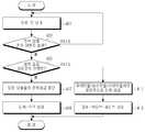
도 5는 사용자 단말이 파워-액티브-세이브 상태에서 파워-오프 상태 또는 파워-온 상태로 천이하는 과정을 도시한 순서도이다.5 is a flowchart illustrating a process of a user terminal transitioning from a power-active-save state to a power-off state or a power-on state.
먼저, 501단계에서 파워-세이브 상태인 사용자 단말은 503단계로 진행하여 전력 상태 천이 이벤트가 발생하는지 여부를 검사한다. 상기 503단계에서 검사 결과, 전력 상태 천이 이벤트가 발생하지 않으면 501단계로 진행하여 파워-액티브-세이브 상태를 유지하고, 전력 상태 천이 이벤트가 발생하면 505단계로 진행한다. 505단계에서는 상기 사용자 단말은 상기 발생한 전력 상태 천이 이벤트가 파워-오프 상태 천이 이벤트인지 검사한다. 상기 검사 결과, 상기 발생한 전력 상태 천이 이벤트가 파워-오프 상태 천이 이벤트일 경우 상기 사용자 단말은 507단계로 진행한다. 507단계에서 사용자 단말은 상기 사용자 단말이 포함하는 모든 모듈의 전력 공급을 중단하고 509단계로 진행한다. 509단계에서 사용자 단말은 파워-오프 상태를 유지한다. 이 때, 사용자 단말이 파워-액티브-세이브 상태에서 파워-오프 상태로의 천이는, 사용자가 사용자 단말의 전력 관련 버튼을 사용하여 전력 상태를 직접 입력하거나 미리 설정된 시간 내에 데이터 송수신이 더 이상 일어나지 않는 것을 검출할 때 발생된다.First, in
한편, 상기 505단계에서 검사 결과 상기 발생한 전력 상태 천이 이벤트가 파워-오프 천이 이벤트가 아닐 경우 상기 사용자 단말은 511단계로 진행한다. 511단계에서 상기 사용자 단말은 상기 발생한 전력 상태 천이 이벤트가 메시지 수신 이벤트인지 검사한다. 여기서, 상기 메시지 수신 이벤트는 페이징 메시지가 수신될 경우 발생되는 이벤트이다. 상기 511단계에서 검사 결과, 상기 발생한 전력 상태 천이 이벤트가 메시지 수신 이벤트일 경우 상기 사용자 단말은 513단계로 진행한다. 513단계에서 사용자 단말은 상기 수신한 페이징 메시지를 확인하고 515단계로 진행한다, 515단계에서 사용자 단말은 상기 사용자 단말이 포함하는 모든 모듈의 전력 공급을 재개하고 517단계로 진행한다. 517단계에서 사용자 단말은 파워-온 상태를 유지한다.In
한편, 상기 511단계에서 상기 발생한 전력 상태 천이 이벤트가 메시지 수신 이벤트가 아닐 경우 상기 515단계로 진행한다. 515단계에서 사용자 단말은 상기 사용자 단말이 포함하는 모든 모듈의 전력 공급을 재개하고 517단계로 진행한다. 517단계에서 사용자 단말은 파워-온 상태를 유지한다. 다음으로 도 6 및 도 7을 참조하여 상기 페이징 메시지 수신에 따른 파워-액티브-세이브 상태에서 파워-온 상태로 천이하는 사용자 단말에 대하여 설명하기로 한다. 후술할 실시예에서 사용자 단말 구조는 앞서 설명한 도 2에서 상세히 설명하였으므로, 하기의 설명에서는 생략하기로 한다.If the generated power state transition event is not a message reception event in
도 6은 본 발명의 제 1 실시예에 따른 파워-액티브-세이브 상태인 사용자 단말의 파워-온 상태로의 상태 천이할 경우의 동작을 도시한 도면이다.FIG. 6 is a diagram illustrating an operation when a state transition to a power-on state of a user terminal in a power-active-save state according to the first embodiment of the present invention.
도 6을 참조하면, 수신 모듈(213)은 무선 통신망으로부터 페이징 메시지를 수신하고,(611단계) 상기 페이징 메시지 수신에 따른 전력 공급 재개를 나타내는 신호를 제어 모듈(209)로 송신한다.(613단계) 상기 제어 모듈(209)은 상기 수신 모듈(213)로부터 수신한 전력 공급 재개 신호를 전력 공급 모듈(201)로 송신한다,(615단계) 이를 통하여 무선 통신 망으로부터 해당 사용자 단말의 통신 재개를 인식한 상기 전력 공급 모듈(201)은 전력이 공급이 되지 않고 있던 모듈들, 즉 디스플레이 모듈(203), 음성 모듈(205), 저장 모듈(207) 및 제어 모듈(209)에게 전력 공급을 재개한다.(617단계)Referring to FIG. 6, the receiving
도 7은 본 발명의 제 2 실시예에 따른 파워-액티브-세이브 상태인 사용자 단말의 파워-온 상태로의 상태 천이할 경우의 동작을 도시한 도면이다.7 is a diagram illustrating an operation when a state transition to a power-on state of a user terminal in a power-active-save state according to a second embodiment of the present invention.
도 7을 참조하면, 수신 모듈(213)은 무선 통신 망으로부터 페이징 메시지를 수신한다(711단계). 상기 페이징 메시지를 수신한 수신 모듈(213)은 전력 공급 재개를 나타내는 신호를 전력 공급 모듈(201)로 송신한다(713단계). 이를 통하여 무선 통신 망으로부터 해당 사용자 단말의 통신 재개를 인식한 전력 공급 모듈(201)은 전력이 공급이 되지 않고 있던 모듈들, 즉 디스플레이 모듈(203), 음성 모듈(205), 저장 모듈(207)과 제어 모듈(209)에 전력 공급을 재개한다(715단계).Referring to FIG. 7, the receiving
본 발명의 상세한 설명에서는 구체적인 실시예에 관해 설명하였으나, 본 발명의 범위에서 벗어나지 않는 한도 내에서 여러 가지 변형이 가능함은 물론이다. 그러므로 본 발명의 범위는 설명된 실시예에 국한되지 않으며, 후술되는 특허청구의 범위뿐만 아니라 이 특허청구의 범위와 균등한 것들에 의해 정해져야 한다.In the detailed description of the present invention, specific embodiments have been described, but various modifications are possible without departing from the scope of the present invention. Therefore, the scope of the present invention should not be limited to the described embodiments, but should be defined not only by the scope of the following claims, but also by those equivalent to the scope of the claims.
상술한 바와 같은 본 발명은 통신 시스템에서 사용자 단말의 전력 제어를 효율적으로 수행할 수 있다. 즉, 전력 소모를 최소화하면서도 통신 시스템에서 제공하는 통신 서비스 송수신을 가능하게 하도록 한다는 이점을 가진다. . 또한 본 발명은 음성 서비스, 인스턴트 메시징(IM: Instant Messaging) 서비스와 같은 항상-온(Always-ON) 기반의 서비스가 사용자 단말에서 수행될 경우에도 효과적으로 그 배터리를 제어함으로써 항상-온 서비스 제공을 가능하게 한다는 이점을 가진다.As described above, the present invention can efficiently perform power control of a user terminal in a communication system. That is, it has the advantage of enabling transmission and reception of communication services provided by a communication system while minimizing power consumption. . In addition, the present invention can provide an always-on service by effectively controlling the battery even when always-on based services such as voice service and instant messaging (IM) service are performed in the user terminal. This has the advantage of
Claims (12)
Translated fromKoreanPriority Applications (2)
| Application Number | Priority Date | Filing Date | Title |
|---|---|---|---|
| KR1020060125733AKR100943621B1 (en) | 2006-12-11 | 2006-12-11 | Power control device and method in communication system |
| US12/001,223US20080141051A1 (en) | 2006-12-11 | 2007-12-11 | Apparatus and method for controlling power in a communication system |
Applications Claiming Priority (1)
| Application Number | Priority Date | Filing Date | Title |
|---|---|---|---|
| KR1020060125733AKR100943621B1 (en) | 2006-12-11 | 2006-12-11 | Power control device and method in communication system |
Publications (2)
| Publication Number | Publication Date |
|---|---|
| KR20080053782A KR20080053782A (en) | 2008-06-16 |
| KR100943621B1true KR100943621B1 (en) | 2010-02-24 |
Family
ID=39499737
Family Applications (1)
| Application Number | Title | Priority Date | Filing Date |
|---|---|---|---|
| KR1020060125733AExpired - Fee RelatedKR100943621B1 (en) | 2006-12-11 | 2006-12-11 | Power control device and method in communication system |
Country Status (2)
| Country | Link |
|---|---|
| US (1) | US20080141051A1 (en) |
| KR (1) | KR100943621B1 (en) |
Cited By (1)
| Publication number | Priority date | Publication date | Assignee | Title |
|---|---|---|---|---|
| WO2011122754A1 (en)* | 2010-04-01 | 2011-10-06 | Lg Electronics Inc. | Method and apparatus for controlling transmit power |
Families Citing this family (5)
| Publication number | Priority date | Publication date | Assignee | Title |
|---|---|---|---|---|
| WO2010094119A1 (en)* | 2009-02-23 | 2010-08-26 | Sierra Wireless, Inc. | Apparatus providing plural wireless transceivers within a desired power budget and associated method |
| EP2494736B1 (en)* | 2009-10-26 | 2019-12-18 | LG Electronics Inc. | Method of controlling network system |
| JP2013041458A (en)* | 2011-08-17 | 2013-02-28 | Canon Inc | Data processing apparatus and control method therefor |
| US9692967B1 (en) | 2015-03-23 | 2017-06-27 | Snap Inc. | Systems and methods for reducing boot time and power consumption in camera systems |
| US10009505B2 (en)* | 2015-04-14 | 2018-06-26 | Apple Inc. | Asynchronously requesting information from a camera device |
Citations (1)
| Publication number | Priority date | Publication date | Assignee | Title |
|---|---|---|---|---|
| KR20000044463A (en)* | 1998-12-30 | 2000-07-15 | 윤종용 | Method of controlling power supply of mobile phone |
Family Cites Families (15)
| Publication number | Priority date | Publication date | Assignee | Title |
|---|---|---|---|---|
| US3603732A (en)* | 1969-06-05 | 1971-09-07 | Rca Corp | Instant-on circuitry for solid state television receivers |
| DE2458302C3 (en)* | 1974-12-10 | 1981-06-04 | Blaupunkt-Werke Gmbh, 3200 Hildesheim | Flyback converter power supply for a television receiver with ultrasonic remote control |
| US5867720A (en)* | 1992-12-14 | 1999-02-02 | Canon Kabushiki Kaisha | Printing apparatus and a method therefor, and information processing apparatus and a method therefor |
| US5566357A (en)* | 1994-10-06 | 1996-10-15 | Qualcomm Incorporated | Power reduction in a cellular radiotelephone |
| DE19611942C2 (en)* | 1996-03-26 | 2003-02-20 | Daimler Chrysler Ag | Semiconductor circuit for an electronic control unit |
| US5802305A (en)* | 1996-05-17 | 1998-09-01 | Microsoft Corporation | System for remotely waking a sleeping computer in power down state by comparing incoming packet to the list of packets storing on network interface card |
| US6289464B1 (en)* | 1998-01-07 | 2001-09-11 | Microsoft Corporation | Receiving wireless information on a mobile device with reduced power consumption |
| DE59914852D1 (en)* | 1998-03-10 | 2008-10-09 | Nxp Bv | SYSTEM FOR TRANSFERRING DATA |
| TW493120B (en)* | 2000-02-11 | 2002-07-01 | Rf Link Systems Inc | Waking up system and method for universal serial bus of wireless computer input device |
| US6671660B2 (en)* | 2001-04-19 | 2003-12-30 | Onwafer Technologies, Inc. | Methods and apparatus for power control |
| US6943667B1 (en)* | 2002-02-25 | 2005-09-13 | Palm, Inc. | Method for waking a device in response to a wireless network activity |
| US7230933B2 (en)* | 2002-04-17 | 2007-06-12 | Microsoft Corporation | Reducing idle power consumption in a networked battery operated device |
| US7073077B1 (en)* | 2003-05-09 | 2006-07-04 | National Semiconductor Corporation | Apparatus for cutting power to processing circuitry in a network interface |
| TWI225200B (en)* | 2003-06-24 | 2004-12-11 | Lite On Technology Corp | Fast wake-up wireless signal receiving device |
| US7398408B2 (en)* | 2004-11-24 | 2008-07-08 | Conexant Systems, Inc. | Systems and methods for waking up wireless LAN devices |
- 2006
- 2006-12-11KRKR1020060125733Apatent/KR100943621B1/ennot_activeExpired - Fee Related
- 2007
- 2007-12-11USUS12/001,223patent/US20080141051A1/ennot_activeAbandoned
Patent Citations (1)
| Publication number | Priority date | Publication date | Assignee | Title |
|---|---|---|---|---|
| KR20000044463A (en)* | 1998-12-30 | 2000-07-15 | 윤종용 | Method of controlling power supply of mobile phone |
Cited By (2)
| Publication number | Priority date | Publication date | Assignee | Title |
|---|---|---|---|---|
| WO2011122754A1 (en)* | 2010-04-01 | 2011-10-06 | Lg Electronics Inc. | Method and apparatus for controlling transmit power |
| US8743817B2 (en) | 2010-04-01 | 2014-06-03 | Lg Electronics Inc. | Method and apparatus for controlling transmit power |
Also Published As
| Publication number | Publication date |
|---|---|
| US20080141051A1 (en) | 2008-06-12 |
| KR20080053782A (en) | 2008-06-16 |
Similar Documents
| Publication | Publication Date | Title |
|---|---|---|
| US7672682B2 (en) | Managing page cycle periods of access terminals | |
| KR101016579B1 (en) | Power control method and system in communication system | |
| US9301252B2 (en) | Reducing power consumption by a wireless communication device with multiple wireless communication modems | |
| US8340049B2 (en) | Mobile terminal and handover method thereof | |
| KR101945897B1 (en) | Method and apparatus for exchanging sip options message for capability discovery of rich communication suite in a portable terminal | |
| KR101162384B1 (en) | Apparatus for controlling a communication unit and method for controlling thereof | |
| KR100943621B1 (en) | Power control device and method in communication system | |
| KR101735342B1 (en) | Communication Control Method For Dual Standby Portable Device And Dual Standby Portable Device supporting the same | |
| WO2019210754A1 (en) | Network search control method and device, and mobile terminal | |
| US9053463B2 (en) | Apparatus and method for pushing e-mail to portable terminal in e-mail system | |
| US8918123B2 (en) | Method and apparatus for reducing standby power | |
| US7890779B2 (en) | Method and apparatus for providing updated information using power control in portable terminal device | |
| CN108476441B (en) | Cell switching method and terminal equipment | |
| WO2022021787A1 (en) | Antenna control method and apparatus, and terminal device | |
| KR101964932B1 (en) | Mobile terminal comprising sim card and battery managing method thereof | |
| WO2024067356A1 (en) | Network connection method and apparatus, and electronic device and readable storage medium | |
| US8199795B2 (en) | Communication device and data transmission method between at least two communication devices | |
| KR100622875B1 (en) | Mobile communication terminal and method thereof for improving reception waiting time | |
| KR101727042B1 (en) | Method for controlling suspend mode in dual modem device and apparatus therefor | |
| KR20090011576A (en) | Computer system that provides internet phone service and its control method |
Legal Events
| Date | Code | Title | Description |
|---|---|---|---|
| PA0109 | Patent application | St.27 status event code:A-0-1-A10-A12-nap-PA0109 | |
| A201 | Request for examination | ||
| P11-X000 | Amendment of application requested | St.27 status event code:A-2-2-P10-P11-nap-X000 | |
| P13-X000 | Application amended | St.27 status event code:A-2-2-P10-P13-nap-X000 | |
| PA0201 | Request for examination | St.27 status event code:A-1-2-D10-D11-exm-PA0201 | |
| PG1501 | Laying open of application | St.27 status event code:A-1-1-Q10-Q12-nap-PG1501 | |
| D13-X000 | Search requested | St.27 status event code:A-1-2-D10-D13-srh-X000 | |
| D14-X000 | Search report completed | St.27 status event code:A-1-2-D10-D14-srh-X000 | |
| E902 | Notification of reason for refusal | ||
| PE0902 | Notice of grounds for rejection | St.27 status event code:A-1-2-D10-D21-exm-PE0902 | |
| E13-X000 | Pre-grant limitation requested | St.27 status event code:A-2-3-E10-E13-lim-X000 | |
| P11-X000 | Amendment of application requested | St.27 status event code:A-2-2-P10-P11-nap-X000 | |
| P13-X000 | Application amended | St.27 status event code:A-2-2-P10-P13-nap-X000 | |
| E701 | Decision to grant or registration of patent right | ||
| PE0701 | Decision of registration | St.27 status event code:A-1-2-D10-D22-exm-PE0701 | |
| GRNT | Written decision to grant | ||
| PR0701 | Registration of establishment | St.27 status event code:A-2-4-F10-F11-exm-PR0701 | |
| PR1002 | Payment of registration fee | St.27 status event code:A-2-2-U10-U11-oth-PR1002 Fee payment year number:1 | |
| PG1601 | Publication of registration | St.27 status event code:A-4-4-Q10-Q13-nap-PG1601 | |
| R18-X000 | Changes to party contact information recorded | St.27 status event code:A-5-5-R10-R18-oth-X000 | |
| FPAY | Annual fee payment | Payment date:20130130 Year of fee payment:4 | |
| PR1001 | Payment of annual fee | St.27 status event code:A-4-4-U10-U11-oth-PR1001 Fee payment year number:4 | |
| FPAY | Annual fee payment | Payment date:20140128 Year of fee payment:5 | |
| PR1001 | Payment of annual fee | St.27 status event code:A-4-4-U10-U11-oth-PR1001 Fee payment year number:5 | |
| FPAY | Annual fee payment | Payment date:20150129 Year of fee payment:6 | |
| PR1001 | Payment of annual fee | St.27 status event code:A-4-4-U10-U11-oth-PR1001 Fee payment year number:6 | |
| FPAY | Annual fee payment | Payment date:20160128 Year of fee payment:7 | |
| PR1001 | Payment of annual fee | St.27 status event code:A-4-4-U10-U11-oth-PR1001 Fee payment year number:7 | |
| FPAY | Annual fee payment | Payment date:20170125 Year of fee payment:8 | |
| PR1001 | Payment of annual fee | St.27 status event code:A-4-4-U10-U11-oth-PR1001 Fee payment year number:8 | |
| P22-X000 | Classification modified | St.27 status event code:A-4-4-P10-P22-nap-X000 | |
| FPAY | Annual fee payment | Payment date:20180130 Year of fee payment:9 | |
| PR1001 | Payment of annual fee | St.27 status event code:A-4-4-U10-U11-oth-PR1001 Fee payment year number:9 | |
| FPAY | Annual fee payment | Payment date:20190130 Year of fee payment:10 | |
| PR1001 | Payment of annual fee | St.27 status event code:A-4-4-U10-U11-oth-PR1001 Fee payment year number:10 | |
| PC1903 | Unpaid annual fee | St.27 status event code:A-4-4-U10-U13-oth-PC1903 Not in force date:20200213 Payment event data comment text:Termination Category : DEFAULT_OF_REGISTRATION_FEE | |
| P22-X000 | Classification modified | St.27 status event code:A-4-4-P10-P22-nap-X000 | |
| PC1903 | Unpaid annual fee | St.27 status event code:N-4-6-H10-H13-oth-PC1903 Ip right cessation event data comment text:Termination Category : DEFAULT_OF_REGISTRATION_FEE Not in force date:20200213 |