KR100942170B1 - Laminoplasty plate - Google Patents
Laminoplasty plateDownload PDFInfo
- Publication number
- KR100942170B1 KR100942170B1KR1020090092723AKR20090092723AKR100942170B1KR 100942170 B1KR100942170 B1KR 100942170B1KR 1020090092723 AKR1020090092723 AKR 1020090092723AKR 20090092723 AKR20090092723 AKR 20090092723AKR 100942170 B1KR100942170 B1KR 100942170B1
- Authority
- KR
- South Korea
- Prior art keywords
- forming plate
- bone screw
- bone
- incision
- arch forming
- Prior art date
- Legal status (The legal status is an assumption and is not a legal conclusion. Google has not performed a legal analysis and makes no representation as to the accuracy of the status listed.)
- Active
Links
- 210000000988bone and boneAnatomy0.000claimsabstractdescription126
- 230000008878couplingEffects0.000claimsabstractdescription51
- 238000010168coupling processMethods0.000claimsabstractdescription51
- 238000005859coupling reactionMethods0.000claimsabstractdescription51
- 238000000034methodMethods0.000claimsabstractdescription28
- 230000000295complement effectEffects0.000claimsdescription13
- 238000000465mouldingMethods0.000claimsdescription3
- 238000001356surgical procedureMethods0.000description9
- 230000003412degenerative effectEffects0.000description6
- 208000020307Spinal diseaseDiseases0.000description5
- 230000000694effectsEffects0.000description4
- 208000005198spinal stenosisDiseases0.000description4
- 230000033001locomotionEffects0.000description3
- 239000000463materialSubstances0.000description2
- 238000012986modificationMethods0.000description2
- 230000004048modificationEffects0.000description2
- 239000011148porous materialSubstances0.000description2
- 208000031481Pathologic ConstrictionDiseases0.000description1
- 238000005452bendingMethods0.000description1
- 210000001185bone marrowAnatomy0.000description1
- 238000005266castingMethods0.000description1
- 238000010586diagramMethods0.000description1
- 230000009545invasionEffects0.000description1
- 238000003825pressingMethods0.000description1
- 238000000926separation methodMethods0.000description1
- 230000009528severe injuryEffects0.000description1
- 239000007787solidSubstances0.000description1
- 210000000278spinal cordAnatomy0.000description1
- 210000000273spinal nerve rootAnatomy0.000description1
- 230000036262stenosisEffects0.000description1
- 208000037804stenosisDiseases0.000description1
- 210000000115thoracic cavityAnatomy0.000description1
Images


Classifications
- A—HUMAN NECESSITIES
- A61—MEDICAL OR VETERINARY SCIENCE; HYGIENE
- A61B—DIAGNOSIS; SURGERY; IDENTIFICATION
- A61B17/00—Surgical instruments, devices or methods
- A61B17/56—Surgical instruments or methods for treatment of bones or joints; Devices specially adapted therefor
- A61B17/58—Surgical instruments or methods for treatment of bones or joints; Devices specially adapted therefor for osteosynthesis, e.g. bone plates, screws or setting implements
- A61B17/68—Internal fixation devices, including fasteners and spinal fixators, even if a part thereof projects from the skin
- A61B17/70—Spinal positioners or stabilisers, e.g. stabilisers comprising fluid filler in an implant
- A61B17/7059—Cortical plates
- A—HUMAN NECESSITIES
- A61—MEDICAL OR VETERINARY SCIENCE; HYGIENE
- A61B—DIAGNOSIS; SURGERY; IDENTIFICATION
- A61B17/00—Surgical instruments, devices or methods
- A61B17/56—Surgical instruments or methods for treatment of bones or joints; Devices specially adapted therefor
- A61B17/58—Surgical instruments or methods for treatment of bones or joints; Devices specially adapted therefor for osteosynthesis, e.g. bone plates, screws or setting implements
- A61B17/68—Internal fixation devices, including fasteners and spinal fixators, even if a part thereof projects from the skin
- A61B17/80—Cortical plates, i.e. bone plates; Instruments for holding or positioning cortical plates, or for compressing bones attached to cortical plates
- A—HUMAN NECESSITIES
- A61—MEDICAL OR VETERINARY SCIENCE; HYGIENE
- A61B—DIAGNOSIS; SURGERY; IDENTIFICATION
- A61B17/00—Surgical instruments, devices or methods
- A61B17/02—Surgical instruments, devices or methods for holding wounds open, e.g. retractors; Tractors
- A61B17/025—Joint distractors
- A61B2017/0256—Joint distractors for the spine
Landscapes
- Health & Medical Sciences (AREA)
- Orthopedic Medicine & Surgery (AREA)
- Life Sciences & Earth Sciences (AREA)
- Surgery (AREA)
- Neurology (AREA)
- Heart & Thoracic Surgery (AREA)
- Engineering & Computer Science (AREA)
- Biomedical Technology (AREA)
- Nuclear Medicine, Radiotherapy & Molecular Imaging (AREA)
- Medical Informatics (AREA)
- Molecular Biology (AREA)
- Animal Behavior & Ethology (AREA)
- General Health & Medical Sciences (AREA)
- Public Health (AREA)
- Veterinary Medicine (AREA)
- Surgical Instruments (AREA)
- Prostheses (AREA)
Abstract
Translated fromKoreanDescription
Translated fromKorean본 발명은 척추궁 성형 플레이트에 관한 것으로, 보다 구체적으로는 경추의 극돌기에서부터 외측괴까지의 길이를 가지는 골나사를 사용하여 경추에 대한 고정력을 상당히 향상시킬 수 있는 척추궁 성형 플레이트에 관한 것이다.The present invention relates to a spinal arch forming plate, and more particularly to a spinal arch forming plate that can significantly improve the fixing force to the cervical spine using a bone screw having a length from the spinous process of the cervical spine to the outer lump.
매년 많은 수의 사람들이 경추(cervical), 요추(lumbar), 흉관(thoracic)과 같은 척추 부위의 심한 손상으로 고통받고 있다. 특히, 상당한 수의 사람들에게 고통을 주는 퇴행성 척추 질환 중에서도, 퇴행성 척추 협착증(degenerative spine stenosis)이 대표적인 척추 질환이다.Every year, a large number of people suffer from severe damage to the spine, such as the cervical, lumbar, and thoracic. In particular, degenerative spine stenosis is a representative spinal disease among degenerative spinal diseases that cause a significant number of people.
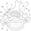
이하에서는 도 1을 참고하여, 경추, 퇴행성 척추 협착증, 척추체 후궁 성형술 및 종래의 척추궁 성형 플레이트에 대하여 설명한다. 여기서, 도 1은 수술 부위인 경추(1) 및 경추에 시술되어 있는 종래의 척추궁 성형 플레이트(20)에 대한 개략도이다.Hereinafter, with reference to Figure 1, the cervical spine, degenerative spinal stenosis, vertebral posterior archplasty and conventional spinal arch molding plate will be described. Here, Figure 1 is a schematic diagram of the
도 1에 나타난 바와 같이, 경추는 극돌기(spinous process)(3), 횡돌 기(transverse process)(5), 외측괴(latteral mass)(11, 13), 추공(foramen)(15), 추체(body)(17), 횡돌공(19), 극돌기와 횡돌기 사이를 연결하는 추궁판(lamina)(10) 등으로 구성되어 있다.As shown in Figure 1, the cervical spine is a spinous process (3), transverse process (5), lateral mass (11, 13), foramen (15), vertebrae (
그리고, 전술한 퇴행성 척추 협착증이란, 척수(spinal cord)와 신경근(nerve roots)을 포함하고 이들을 보호하는 척추관(spinal canal) 및 척추관이 위치하는 추공(foramen)(15)을 추체(body)(17) 및 추궁판(lamina)(10)이 가압하여 환자에게 고통을 발생시키는 척추 질환이다. 즉, 퇴행성 척추 협착증은 도 1의 추공(15)이 좁아져 척추관이 압박되어 환자가 고통을 느끼게 되는 척추 질환이다.In addition, the degenerative spinal stenosis described above includes a spinal canal and a
이러한 퇴행성 척추 협착증을 치료하기 위해서는 추체(17) 및 추궁판(10)에 의해 척추관 및 척추관이 위치하는 추공(15)에 가해지는 압력을 감압해야 한다. 이러한 원리를 이용한 치료법 중 대표적인 외과적인 치료법이, 추궁판 성형술, 척추 후궁 확장 수술(open door laminoplasty) 또는 척추궁 성형술이라고도 불리는 척추체 후궁 성형술(laminoplasty)이다.In order to treat such degenerative spinal stenosis, the pressure exerted on the
상기 척추체 후궁 성형술은 추공(15)을 감싸고 추공의 경계를 한정하는 골질의 척추골 구조들(추체(17), 추궁판(10) 등) 중 하나 또는 그 이상을 교환하여, 추공(17)의 공간을 넓혀 추공에 가해지는 압력을 제거하는 외과 수술이다. 이때, 공간 확보를 위해 수술 시에 추체(17) 또는 추궁판(10)의 일부를 절개하여 벌어진 공간을 골 이식편(bone graft)을 사용하여 메우고, 척추궁 성형 플레이트(laminoplasty plate)로 골 이식편을 고정한다. 여기서, 척추궁 성형 플레이트는 척추궁 성형술에서 가장 핵심적인 구성요소이고, 상기 척추궁 성형 플레이트의 척 추체에 대한 고정력은 척추궁 성형 플레이트의 우수성을 결정하는 매우 중요한 특성이다.The vertebral posterior archplasty replaces one or more of the vertebral vertebral structures (
도 1에 도시된 바와 같이, 종래의 척추궁 성형 플레이트(20)는 경추(1)의 제1 절개부(7)에 고정되는 제1 고정단부, 경추(1)의 제2 절개부(9)에 고정되는 제2 고정단부, 골 이식편(21)이 고정되는 연결 부재 및 상기 제1 고정단부와 제2 고정단부에서 제1 절개부(7) 및 제2 절개부(9)를 관통하여 고정되는 골나사(23, bone screw)들로 구성되어 있다.As shown in FIG. 1, the conventional spinal
뼈의 단면 구조를 보면, 뼈는 기계적 지지부 역할을 하는 단단한 치밀골(compact bone) 및 치밀골 내에서 골수를 포함하는 해면골(sponge bone)로 구성되는데, 상기 종래 척추궁 성형 플레이트(20)의 골나사(23)는 일반적으로 추궁판(10)의 얇은 치밀골에 기계적으로 체결되어 고정된다. 이러한 방식으로 경추에 고정된 골나사(23)는 경추에 대한 고정력이 약하여 상기 골나사(23)가 종종 추궁판(10)에서 탈락되는 현상이 발생하는 문제점이 있었다. 이렇게 추궁판(10)에 고정된 골나사가 탈락되는 경우, 척추궁 성형 플레이트가 척추체에서 이탈하게 되고, 이로 인해 추궁이 개방되어 환자에게 심각한 척추 질환을 재발시킬 위험이 있으므로, 경추에 대한 고정력을 상당히 향상시킨 척추궁 성형 플레이트에 대한 필요성이 제기되어 왔다.Looking at the cross-sectional structure of the bone, the bone is composed of a solid compact bone (compact bone) that acts as a mechanical support and a sponge bone including the bone marrow in the compact bone, the bone screw of the conventional spinal arch forming plate 20 ( 23 is generally fastened and fixed mechanically to the thin dense bone of the
본 발명의 목적은 종래 기술의 문제점을 해결할 수 있는 척추궁 성형 플레이트를 제공하는 것이다.It is an object of the present invention to provide a spinal arch forming plate which can solve the problems of the prior art.
본 발명의 목적은 척추궁 성형 플레이트의 척추체에 대한 고정력을 향상시키는 것이다.It is an object of the present invention to improve fixation of the vertebral arch forming plate to the vertebral body.
본 발명의 또 다른 목적은 척추궁 성형 플레이트의 골나사가 척추체에서 탈락되는 현상을 방지하는 것이다.Still another object of the present invention is to prevent the bone screw of the vertebral arch forming plate from falling off the vertebral body.
상기 목적을 달성하기 위하여, 본 발명에 따른 척추궁 성형 플레이트는, 경추의 극돌기(spinous process) 쪽에 위치하는 제1 절개부에 고정되고, 골나사가 체결되는 제1 추판 결합부가 형성되어 있는 제1 단부; 경추의 횡돌기(transverse process) 쪽에 위치하는 제2 절개부에 고정되고, 골나사가 체결되는 제2 추판 결합부가 형성되어 있는 제2 단부; 및 상기 제1 단부와 상기 제2 단부 사이에 뻗어있고, 골 이식편이 고정되는 골 이식편 고정부가 형성되어 있는 중간 부재;를 포함하고, 상기 제1 추판 결합부에 체결되는 골나사는, 제1 절개부부터 제2 절개부의 반대쪽에 위치하는 경추의 외측괴(lateral mass)까지 뻗어있어 상기 외측괴에 고정되는 것을 특징으로 한다.In order to achieve the above object, the spinal arch forming plate according to the present invention is fixed to the first incision located on the spinous process (spinous process) side of the cervical spine, the first screw plate engaging portion is formed is fastened to the bone screw is formed End; A second end secured to a second incision located at the transverse process side of the cervical spine, and having a second spindle coupling to which the bone screw is fastened; And an intermediate member extending between the first end and the second end and having a bone graft fixation portion to which the bone graft is fixed. It extends from the part to the lateral mass of the cervical vertebrae located opposite the second incision and is fixed to the lateral mass.
이와 같이, 제1 절개부에서부터 제2 절개부의 반대쪽에 위치하는 경추의 외측괴까지의 길이를 가지는 골나사를 사용함으로써, 골나사를 제1 절개부 및 외측괴 에 견고하게 고정할 수 있어, 최종적으로 척추궁 성형 플레이트의 경추에 대한 고정력을 상당히 향상시킬 수 있다.Thus, by using a bone screw having a length from the first incision to the outer ingot of the cervical vertebrae located on the opposite side of the second incision, the bone screw can be firmly fixed to the first incision and the outer ingot and finally This can significantly improve the fixation of the cervical spine to the cervical spine.
바람직하게는, 상기 척추궁 성형 플레이트는, 상기 제1 단부 및 상기 중간 부재 사이에 위치되고, 골나사가 체결되는 하나 이상의 추가 결합부가 형성되어 있는 추가 부재;를 더 포함할 수 있다.Preferably, the spinal arch forming plate may further include an additional member positioned between the first end and the intermediate member and having one or more additional coupling portions to which bone screws are fastened.
이렇게 추가 부재를 형성함으로써, 제1 추판 결합부의 골나사가 제1 절개부 및 외측괴에 보다 잘 고정되도록 하여, 척추궁 성형 플레이트의 경추에의 고정력을 더 향상시킬 수 있다.By forming the additional member in this way, the bone screw of the first lumbar linkage portion can be more secured to the first incision and the lateral ingot, and the fixation force to the cervical spine of the spinal arch forming plate can be further improved.
또한, 상기 제2 추판 결합부에 체결되는 골나사도, 제2 절개부부터 제2 절개부 부근에 위치하는 경추의 외측괴까지 뻗어있어 상기 외측괴에 고정되는 것이 바람직하다.In addition, the bone screw fastened to the second disc coupling portion also extends from the second incision to the outer ingot of the cervical vertebrae located near the second incision, and is preferably fixed to the outer ingot.
또한, 바람직하게는, 골나사의 헤드부에는 각각 선택적으로 나사산이 형성되어 있고, 헤드부에 나사산이 형성된 골나사의 경우, 상기 추가 결합부 또는 상기 추판 결합부에는 상기 골나사의 헤드부의 나사산에 상보적인 나사산이 각각 형성되어 있을 수 있다.Preferably, the head of the bone screw is selectively formed with a thread, and in the case of the bone screw with the thread formed in the head, the additional coupling part or the disc coupling part may be provided with a thread of the head of the bone screw. Complementary threads may each be formed.
또한, 바람직하게는, 골나사의 헤드부에 나사산이 형성되어 있지 않은 경우, 상기 추가 결합부 또는 추판 결합부는 상기 골나사의 헤드부 형상에 상보적인 형상을 가질 수 있다.Further, preferably, when no thread is formed in the head portion of the bone screw, the additional coupling portion or the disc coupling portion may have a shape complementary to the shape of the head portion of the bone screw.
또한, 바람직하게는, 상기 제2 단부에는, 두 개 이상의 제2 추판 결합부가 상기 척추궁 성형 플레이트의 길이 방향에 수직으로 형성되어 있을 수 있다.In addition, preferably, at least two second spindle coupling parts may be formed perpendicular to the longitudinal direction of the spinal arch forming plate at the second end.
또한, 바람직하게는, 상기 제2 단부에는, 두 개 이상의 제2 추판 결합부가 상기 척추궁 성형 플레이트의 길이 방향을 따라 형성되어 있을 수도 있다.In addition, preferably, at least two second spindle coupling parts may be formed along the longitudinal direction of the spinal arch forming plate at the second end.
이와 같은 본 발명에 의한 척추궁 성형 플레이트에 의하면, 척추궁 성형 플레이트를 척추체에 고정시키는 고정력을 상당히 향상시킬 수 있는 효과가 있고, 골나사가 척추체에서 탈락되는 현상을 방지할 수 있는 효과가 있다.According to the spinal arch forming plate according to the present invention, there is an effect that can significantly improve the fixing force for fixing the spinal arch forming plate to the vertebral body, it is possible to prevent the phenomenon that the bone screw falling off the vertebral body.
게다가, 이로 인해, 척추궁 성형 플레이트의 이탈로 인해 발생할 수 있는 척추체 후궁 성형술의 부작용 및 후유증을 방지할 수 있어, 환자가 이러한 부작용 등으로 수차례 수술받아야 하는 번거로움 및 고통을 제거할 수 있는 효과가 있을 뿐만 아니라, 재수술로 인한 경제적 손실을 감소시킬 수 있는 효과도 있다.In addition, this prevents the side effects and sequelae of the vertebral posterior arch surgery that may occur due to the separation of the vertebral arch molding plate, thereby removing the hassle and pain that the patient has to undergo surgery several times due to such side effects. Not only that, but it also has the effect of reducing the economic loss from reoperation.
이하 도면을 참고하여 본 발명의 바람직한 실시예에 대해 구체적으로 설명하기로 한다. 참고로, 본 발명의 실시예를 설명함에 있어서, 관련된 공지 기능 혹은 구성에 대한 구체적인 설명이 본 발명의 요지를 불명확하게 할 염려가 있다고 판단되는 경우 그에 대한 상세한 설명은 생략한다.Hereinafter, exemplary embodiments of the present invention will be described in detail with reference to the accompanying drawings. For reference, in describing the embodiments of the present invention, if it is determined that a detailed description of a related known function or configuration may make the gist of the present invention unclear, the detailed description thereof will be omitted.
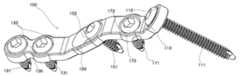
도 2 및 도 3은 본 발명에 따른 척추궁 성형 플레이트(100)의 두 가지 실시예에 대한 개략적인 사시도이다. 도 4는 척추궁 성형 플레이트(100)의 중간 부재(150)의 다른 실시예에 대한 개략적인 측면도이다. 도 5는 경추에 시술이 완료된 본 발명의 척추궁 성형 플레이트의 개략도이다. 참고로, 이하에서는, 도 5와 같이 추궁판(10)이 절개되어 골 이식편이 삽입되어 있는 경우, 경추의 극돌기(3) 쪽에 위치하는 추궁판(10)의 절개부를 제1 절개부(7), 경추의 횡돌기(5) 쪽에 위치하는 추궁판(10)의 절개부를 제2 절개부(9)라 한다.2 and 3 are schematic perspective views of two embodiments of spinal
도 2 및 도 3에 도시된 바와 같이, 본 발명의 척추궁 성형 플레이트(100)는 추궁판(10)의 제1 절개부(7)에 고정되는 제1 단부(110), 추궁판(10)의 제2 절개부(9)에 고정되는 제2 단부(130), 상기 제1 단부(110)와 상기 제2 단부(130) 사이에 뻗어 골 이식편을 고정하는 중간 부재(150) 그리고 제1 단부(110), 제2 단부(130) 및 중간 부재(150)에 각각 체결되는 골나사들(111, 131, 151)로 구성되어 있다.As shown in Figures 2 and 3, the spinal
제1 단부(110)는 경추의 극돌기(3) 쪽에 위치하는 제1 절개부(7)에 고정된다. 상기 제1 단부(110)에는, 골나사(111)가 체결되는 제1 추판 결합부(113)가 상기 제1 단부의 두께 방향으로 형성되어 있다. 상기 제1 추판 결합부(113)는 상기 골나사(111)의 헤드부가 안착되어 견고히 결합될 수 있도록 상기 골나사(111) 헤드부의 형상에 상보적인 형상(예를 들어, 원형으로 테이퍼진(tapered) 형상)을 가진다.The
이때, 상기 제1 추판 결합부(113)에 체결되는 골나사(111)는, 제1 절개부(7)에서부터 제2 절개부(9)의 반대쪽에 위치하는 경추의 외측괴(13)까지의 길이를 가진다. 즉, 도 5에 도시된 바와 같이, 상기 제1 추판 결합부(113)의 골나사(111)는 제1 추판 결합부(113)를 수직 방향으로 관통하여, 극돌기(3)에 또는 극돌기(3) 주변에 위치하는 경추의 제1 절개부(7)를 지나 제2 절개부(9)의 반대쪽 추궁판(10)을 관통한 후, 최종적으로 제2 절개부(9)의 반대쪽 외측괴(13)에 고정된다.At this time, the
도 1 및 도 5를 참고해 보면, 추궁판(10)의 치밀골에만 고정되는 종래의 척추궁 성형 플레이트(20)와 달리, 본 발명의 상기 골나사(111)는 제1 절개부(7)의 치밀골에 거의 수직방향으로, 제2 절개부(9)의 반대쪽 추궁판(10)의 치밀골에 추궁판(10)의 길이 방향으로, 그리고 제2 절개부(9)의 반대쪽 외측괴(13)에 수직방향으로 고정되므로, 척추궁 성형 플레이트(100)의 경추에 대한 고정력을 종래 기술보다 훨씬 향상시킬 수 있다. 즉, 나사의 체결력 또는 고정력은 나사의 나사산에 마찰력이 작용하는 면적 및 나사의 나사산에 의해 소성변형되는 면적에 따라 증가하는데, 종래 기술의 골나사(23)는 추궁판(10)의 얇은 치밀골만을 소성변형시키고 종래 기술의 골나사(23)의 나사산은 얇은 추궁판(10)의 치밀골에 대해서만 마찰력 작용을 받는데 비해, 본 발명의 골나사(111)는 제1 절개부(7)의 치밀골, 제2 절개부(9) 반대쪽의 추궁판(10)의 치밀골 및 제2 절개부(9) 반대쪽의 외측괴(13)에서 마찰 작용 및 소성변형 작용하므로, 본 발명의 따른 척추궁 성형 플레이트(100)의 고정력은 종래 기술(20)에 비해 훨씬 향상되는 것이다.1 and 5, unlike the conventional spinal
제2 단부(130)는 경추의 횡돌기(5) 쪽에 위치하는 제2 절개부(9)에 고정된다. 상기 제2 단부(130)에는, 골나사(131)가 체결되는 제2 추판 결합부(133)가 상기 제2 단부의 두께 방향으로 형성되어 있다. 상기 제2 추판 결합부(133)는 상기 골나사(131)의 헤드부가 안착될 수 있도록 상기 골나사(131) 헤드부의 형상에 상보적인 형상(예를 들어, 원형으로 테이퍼진(tapered) 형상)을 가진다. 이때, 상기 제2 추판 결합부(133)에 체결되는 골나사(131)는 일반적으로 제2 절개부(9)에 고정될 수 있는 정도의 길이, 즉 제2 절개부의 치밀골에 고정될 수 있을 정도의 길이를 가진다.The
그러나, 변형 실시예로서, 상기 제2 추판 결합부(133)의 골나사(131) 또한 제1 추판 결합부(113)의 골나사(111)와 유사하게, 제2 절개부(9)에서부터 제2 절개부(9) 부근에 위치하는 경추의 외측괴(11)까지의 길이를 가질 수 있다. 이 경우, 제1 단부의 골나사(111)와 유사한 원리로, 척추궁 성형 플레이트의 경추에 대한 고정력을 상당히 향상시킬 수 있다.However, as a modified embodiment, the
또한, 바람직하게는, 제2 단부(130)에는 제2 추판 결합부(133)가 두 개 이상 형성될 수 있고, 두 개 이상의 상기 제2 추판 결합부(133)는 척추궁 성형 플레이트(100)의 길이 방향에 수직으로 형성되거나(도 2 참고) 또는 척추궁 성형 플레이트(100)의 길이 방향에 평행하게(도 3 참고) 형성될 수 있다. 이렇게 복수의 제2 추판 결합부(133)를 사용함으로써, 제2 단부(130)가 제2 절개부(9)에 더 견고하게 고정될 수 있도록 한다.In addition, preferably, at least two second
상기 제1 단부(110)와 상기 제2 단부(130) 사이에는, 제1 절개부(7)와 제2 절개부(9) 사이를 메울 수 있는 골 이식편이 고정되는 중간 부재(150)가 포함된다. 상기 중간 부재(150)에는 골 이식편을 고정하는 골나사(151)가 위치되는 골 이식편 고정부(153)가 형성되어 있다.Between the
상기 골 이식편 고정부(153)는, 골나사(151)의 헤드부가 안착될 수 있도록 상기 골나사(151) 헤드부의 형상에 상보적인 형상(예를 들어, 원형으로 테이퍼진 형상)을 가진다. 바람직하게는, 상기 골 이식편 고정부(153)의 단면 형상은, 위에 서 골 이식편 고정부(153)를 바라봤을 때 상기 고정수단이 관통할 수 있는 구멍형 또는 슬롯형일 수 있다. 상기 골 이식편 고정부(153)가 슬롯형인 경우, 척추궁 성형술의 시술 과정 동안, 골 이식편 고정부(153)를 관통하여 골 이식편에 체결된 골나사(151)가 좌우로 이동할 수 있는 여유 공간(즉, 슬롯)이 있어, 상기 척추궁 성형 플레이트(100)를 경추(1)에 대해 좌우로 가변적으로 움직이면서 고정할 수 있다. 즉, 척추궁 성형 플레이트(100)에 좌우 자유도를 제공하여 상기 척추궁 성형 플레이트를 경추에 고정하는 과정을 용이하게 한다. 또한, 다른 방법으로, 상기 중간 부재(150)의 골 이식편 고정부(153)는 선택적으로 경추에 대한 고정부로도 사용될 수 있다.The bone
상기 중간 부재(150)의 또 다른 실시예로서, 상기 골 이식편 고정부(153)의 좌우에는 도 4에 도시된 바와 같이 한 쌍의 플랜지(155)가 추공(15) 방향으로 뻗어있다. 상기 한 쌍의 플랜지(155)는 상기 제1 절개부(7)의 절개면과 상기 제2 절개부(9)의 절개면 각각에 접촉한다. 이렇게 상기 플랜지(155)를 상기 제1 절개부(7)의 절개면과 상기 제2 절개부(9)의 절개면에 접촉되는 면적을 향상시키기 위하여, 각각의 플랜지(155)와 상기 중간 부재(150)가 형성하는 각도가 각각의 플랜지(155)에 대응하는 절개부의 절개면의 각도와 거의 동일하도록 상기 플랜지(155)를 형성하는 것이 바람직하다. 이렇게 플랜지(155)를 사용함으로써, 척추궁 성형 플레이트(100)의 좌우로의 움직임을 제한하거나 봉쇄할 수 있다. 이로 인해, 수술 과정에서 척추궁 성형 플레이트(100)를 경추(1)에 예비적으로 고정할 있어 골나사의 고정 과정을 용이하게 할 수 있어 수술 시간을 단축시킬 수 있고, 수술 완료 후 사용으 로 인한 척추궁 성형 플레이트(100)의 좌우 이동을 방지할 수 있어 척추궁 성형 플레이트(100)의 좌우 이동으로 인해 척추궁 성형 플레이트(100)가 경추(1)에서 이탈되는 현상을 방지할 수 있다.In another embodiment of the
또한, 바람직하게는 상기 플랜지(155)의 단부에는 턱(157)이 형성되어 있을 수 있다. 상기 턱(157)은 추공 쪽에 위치하는 상기 제1 절개부(7) 또는 제2 절개부(9)의 내면에 걸릴 수 있도록 형성된다. 이로 인해, 상기 척추궁 성형 플레이트(100)의 경추(1)에의 결합력을 향상시킬 수 있다.In addition, preferably, the jaw 157 may be formed at the end of the
바람직하게는, 상기 제1 단부(110)와 중간 부재(150) 사이에는, 상기 척추궁 성형 플레이트(100)에 제1 절개부(7)의 형상에 대해 상보적인 형상을 제공할 수 있는 추가 부재(170)가 포함될 수 있다. 즉, 제1 단부(110)가 고정되는 제1 절개부(7)의 길이, 형상 및 경사에 맞춰질 수 있도록 그리고 제1 추판 결합부(113)의 골나사(111)가 상기 외측괴(13)에 정확하게 고정될 수 있도록, 하나 이상의 추가 부재(170)가 제1 단부(110)와 중간 부재(150) 사이에 추가적으로 뻗어있을 수 있다. 전술한 역할을 수행하기 위하여, 상기 추가 부재(170)는 제1 단부(110) 및 중간 부재(150)와 일정 각도를 형성할 수 있다.Preferably, between the
바람직하게는, 상기 추가 부재(170)에는 하나 이상의 추가 결합부(173)가 상기 추가 부재의 두께 방향으로 형성되어 있고, 상기 추가 결합부(173)에는 골 이식편 또는 제1 절개부(7)의 일부분에 고정되는 골나사(171)가 체결될 수 있다.Preferably, one or more
이렇게, 추가 부재(170)를 사용함으로써, 제1 추판 결합부(113)의 골나사(111)가 제2 절개부(9)의 반대쪽 추궁판(10)에 거의 평행하게 그리고 제2 절개 부(9)의 반대쪽 외측괴(13)에 거의 수직 방향으로 배열될 수 있도록 하므로, 제1 추판 결합부(113)의 골나사(111)를 제2 절개부(9)의 반대쪽 외측괴(13)에 더 용이하게 고정시킬 수 있다.Thus, by using the
골나사 및 골나사의 결합부의 변형 실시예로서, 상기 골나사들(111, 131, 151, 171)의 헤드부에는 나사산이 형성되어 있을 수 있고, 골 이식재 고정부(153), 상기 추가 결합부(173) 및 상기 추판 결합부(113, 133)에는 상기 골나사(111, 131, 151, 171) 헤드부의 나사산에 상보적인 나사산이 형성되어 있을 수 있다. 따라서, 상기 골나사들의 몸통부는 제1 및 제2 절개부(7, 9), 외측괴(11, 13) 또는 골 이식재에 고정되고, 상기 골나사들의 헤드부는 상기 추가 결합부(173) 및 상기 추판 결합부(113, 133)에 고정될 수 있어, 상기 골나사들은 2단으로 고정될 수 있다.As a modified embodiment of the coupling portion of the bone screw and bone screw, the head portion of the bone screws (111, 131, 151, 171) may be threaded, bone graft
이런 방식의 골나사 헤드부 및 상기 골나사 헤드부가 체결되는 결합부의 나사산 구조로 인해, 상기 골나사들(111, 131, 151, 171)은 척추궁 성형 플레이트(100)에 더 견고하게 고정될 것이며, 이로 인해 척추궁 성형 플레이트(100)에서 골나사가 탈락되는 현상을 방지할 수 있고, 추궁에서 골나사가 탈락되는 현상도 방지할 수 있다.Due to the threaded structure of the bone screw head portion and the coupling portion to which the bone screw head portion is fastened, the bone screws 111, 131, 151, and 171 will be more firmly fixed to the spinal
또한, 하나의 척추궁 성형 플레이트(100) 내에서, 각 골나사 및 각 골나사의 결합부는 각각 선택적으로 또는 조합적으로, 골나사와 상기 골나사의 헤드부 형상에 상보적인 형상을 가지는 결합부로 형성될 수 있거나, 또는 나사산이 형성된 헤드부를 가지는 골나사와 상기 헤드부의 나사산에 상보적인 나사산을 가지는 결합부로 형성될 수도 있다. 예를 들어, 상기 제1 단부(110)의 골나사(111)의 헤드부에 나사산이 형성되어 있고, 상기 제1 추판 결합부(113)에는 상기 골나사(111)의 헤드부에 상보적인 나사산이 형성되어 있으나; 상기 제2 단부(130)의 골나사(121), 중간 부재(150)의 골나사(151), 추가 부재(170)의 골나사(171)에는 나사산이 형성되어 있지 않고, 상기 제2 추판 결합부(133), 골 이식재 고정부(153) 및 추가 결합부(173)는 각각 자신에 안착되는 골나사의 헤드 형상에 상보적인 형상을 가지도록 구성될 수 있다.In addition, within one spinal
상기 제1 단부(110), 상기 제2 단부(130), 상기 중간 부재(150) 및 상기 추가 부재(170)는 바람직하게는 시술 부위인 추궁판(10)의 형상에 맞춰지도록 서로 일정 각도로 경사지게 형성될 수 있고, 일체형으로 형성될 수 있다. 상기 각 구성부 간의 일정 각도는 벤딩 공정으로 형성될 수 있으나, 다른 기계적 가공으로도 형성될 수 있다. 또한, 바람직하게는 주조 공정을 이용하여 상기 척추궁 성형 플레이트(100)를 간단하게 제조할 수 있다.The
게다가, 특히 바람직하게는, 본 발명인 척추궁 성형 플레이트(100)는 경추 이외의 척추골에도 적용할 수 있다.Moreover, particularly preferably, the spinal
이상에서는 본 발명의 바람직한 실시예에 대하여 도시하고 또한 설명하였으나, 본 발명은 상기한 실시예에 한정되지 않고, 이하 청구범위에서 청구하는 본 발명의 요지를 벗어남이 없이 당해 발명의 분야에서 통상의 지식을 가진 자라면 누구든지 다양한 변형실시가 가능함은 물론이며, 그와 같은 변형은 청구범위의 기재 범위 내에 있게 된다.Although the preferred embodiments of the present invention have been shown and described above, the present invention is not limited to the above-described embodiments, and the general knowledge in the field of the present invention without departing from the gist of the present invention as claimed in the following claims. Anyone with a variety of modifications are possible, of course, such modifications are within the scope of the claims.
도 1은 척추궁 성형수술 부위인 경추 및 종래의 척추궁 성형 플레이트에 대한 개략도이고,1 is a schematic view of the cervical spine and the spinal arch forming plate of the conventional spinal arch surgery,
도 2는 본 발명에 따른 실시예의 사시도이고,2 is a perspective view of an embodiment according to the present invention,
도 3은 본 발명에 따른 다른 실시예의 사시도이고,3 is a perspective view of another embodiment according to the present invention,
도 4는 다른 실시예의 중간 부재를 포함하는 척추궁 성형 플레이트의 개략적인 측면도이고,4 is a schematic side view of a spinal arch forming plate including an intermediate member of another embodiment,
도 5는 경추에 시술이 완료된 본 발명에 따른 척추궁 성형 플레이트의 개략도이다.Figure 5 is a schematic view of the spinal arch forming plate according to the present invention the cervical spine is completed.
<도면의 주요 부분에 대한 부호의 설명><Explanation of symbols for the main parts of the drawings>
1 : 경추3 : 극돌기1: cervical spine 3: spinous process
5 : 횡돌기7 : 제1 절개부5: traverse protrusion 7: first incision
9 : 제2 절개부10 : 추궁판9: second incision 10: plaque plate
11, 13 : 외측괴15 : 추공11, 13: lateral ingot 15: invasion
17 : 추체19 : 횡돌공17: vertebrae 19: roll
20 : 종래의 척추궁 성형 플레이트20: conventional spinal arch forming plate
21 : 골 이식편23, 111, 131, 151, 171 : 골나사21:
100 : 본 발명의 척추궁 성형 플레이트100: spinal arch forming plate of the present invention
110 : 제1 단부113 : 제1 추판 결합부110: first end 113: first plate coupling portion
130 : 제2 단부133 : 제2 추판 결합부130: second end 133: second plate coupling portion
150 : 중간 부재153 : 골 이식편 고정부150: intermediate member 153: bone graft fixture
155 : 플랜지170 : 추가 부재155 flange 170: additional member
173 : 추가 결합부173: additional coupling
Claims (8)
Translated fromKoreanPriority Applications (1)
| Application Number | Priority Date | Filing Date | Title |
|---|---|---|---|
| KR1020090092723AKR100942170B1 (en) | 2009-09-29 | 2009-09-29 | Laminoplasty plate |
Applications Claiming Priority (1)
| Application Number | Priority Date | Filing Date | Title |
|---|---|---|---|
| KR1020090092723AKR100942170B1 (en) | 2009-09-29 | 2009-09-29 | Laminoplasty plate |
Publications (1)
| Publication Number | Publication Date |
|---|---|
| KR100942170B1true KR100942170B1 (en) | 2010-02-12 |
Family
ID=42083358
Family Applications (1)
| Application Number | Title | Priority Date | Filing Date |
|---|---|---|---|
| KR1020090092723AActiveKR100942170B1 (en) | 2009-09-29 | 2009-09-29 | Laminoplasty plate |
Country Status (1)
| Country | Link |
|---|---|
| KR (1) | KR100942170B1 (en) |
Cited By (7)
| Publication number | Priority date | Publication date | Assignee | Title |
|---|---|---|---|---|
| KR100997811B1 (en) | 2010-08-18 | 2010-12-02 | 박윤관 | Plates for shaping and fixing the vertebrae of the spine |
| CN105266877A (en)* | 2015-11-26 | 2016-01-27 | 广州聚生生物科技有限公司 | Spinal column vertebral plate open-door fixing system |
| US9717541B2 (en) | 2015-04-13 | 2017-08-01 | DePuy Synthes Products, Inc. | Lamina implants and methods for spinal decompression |
| JP2019526417A (en)* | 2016-09-07 | 2019-09-19 | スパインウェルディング・アクチェンゲゼルシャフトSpinewelding Ag | Implant fixation |
| CN114027959A (en)* | 2021-11-30 | 2022-02-11 | 迪恩医疗科技有限公司 | Hinged Laminar Fixation Plate |
| CN117017462A (en)* | 2023-09-07 | 2023-11-10 | 上海三友医疗器械股份有限公司 | Be used for cervical vertebra vertebral canal to enlarge forming device and installation device |
| KR20250076862A (en) | 2023-11-23 | 2025-05-30 | 주식회사 에이스메디코프 | Fixation plate assembly for laminoplasty with improved function |
Citations (3)
| Publication number | Priority date | Publication date | Assignee | Title |
|---|---|---|---|---|
| EP0599766A1 (en) | 1992-09-07 | 1994-06-01 | José Vicente Barbera Alacreu | Cervical vertebral fusion system |
| US20030236528A1 (en)* | 2002-06-24 | 2003-12-25 | Thramann Jeffrey J | Impactor for use with cervical plate |
| US20040158246A1 (en)* | 1998-04-30 | 2004-08-12 | Sofamor S.N.C. | Anterior implant for the spine |
- 2009
- 2009-09-29KRKR1020090092723Apatent/KR100942170B1/enactiveActive
Patent Citations (3)
| Publication number | Priority date | Publication date | Assignee | Title |
|---|---|---|---|---|
| EP0599766A1 (en) | 1992-09-07 | 1994-06-01 | José Vicente Barbera Alacreu | Cervical vertebral fusion system |
| US20040158246A1 (en)* | 1998-04-30 | 2004-08-12 | Sofamor S.N.C. | Anterior implant for the spine |
| US20030236528A1 (en)* | 2002-06-24 | 2003-12-25 | Thramann Jeffrey J | Impactor for use with cervical plate |
Cited By (10)
| Publication number | Priority date | Publication date | Assignee | Title |
|---|---|---|---|---|
| KR100997811B1 (en) | 2010-08-18 | 2010-12-02 | 박윤관 | Plates for shaping and fixing the vertebrae of the spine |
| US9717541B2 (en) | 2015-04-13 | 2017-08-01 | DePuy Synthes Products, Inc. | Lamina implants and methods for spinal decompression |
| US10342584B2 (en) | 2015-04-13 | 2019-07-09 | DePuy Synthes Products, Inc. | Lamina implants and methods for spinal decompression |
| US11116551B2 (en) | 2015-04-13 | 2021-09-14 | DePuy Synthes Products, Inc. | Lamina implants and methods for spinal decompression |
| CN105266877A (en)* | 2015-11-26 | 2016-01-27 | 广州聚生生物科技有限公司 | Spinal column vertebral plate open-door fixing system |
| JP2019526417A (en)* | 2016-09-07 | 2019-09-19 | スパインウェルディング・アクチェンゲゼルシャフトSpinewelding Ag | Implant fixation |
| US11179179B2 (en) | 2016-09-07 | 2021-11-23 | Spinewelding Ag | Implant fixation |
| CN114027959A (en)* | 2021-11-30 | 2022-02-11 | 迪恩医疗科技有限公司 | Hinged Laminar Fixation Plate |
| CN117017462A (en)* | 2023-09-07 | 2023-11-10 | 上海三友医疗器械股份有限公司 | Be used for cervical vertebra vertebral canal to enlarge forming device and installation device |
| KR20250076862A (en) | 2023-11-23 | 2025-05-30 | 주식회사 에이스메디코프 | Fixation plate assembly for laminoplasty with improved function |
Similar Documents
| Publication | Publication Date | Title |
|---|---|---|
| KR100942170B1 (en) | Laminoplasty plate | |
| JP4866418B2 (en) | System, apparatus and method for spinal stabilization | |
| KR101149963B1 (en) | Rod-plates anterior system for the correction of spinal deformities | |
| EP2323574B1 (en) | Interspinous spacer assembly | |
| JP2015519148A (en) | Orthopedic device with locking mechanism | |
| US20100063505A1 (en) | Bone plate | |
| KR101272242B1 (en) | Spinal correction system | |
| KR100896043B1 (en) | Rod clamp | |
| JP2006524114A (en) | Bone fixation plate device and method of using the same | |
| MXPA03009106A (en) | Spinal osteosynthesis device and preparation method. | |
| KR101599607B1 (en) | Screw fixing apparatus | |
| US20130261666A1 (en) | Interspinous fixation device | |
| KR102201132B1 (en) | Laminoplasty system | |
| JP2010506672A (en) | Orthopedic implant assembly | |
| US20120265213A1 (en) | Surgical distraction instrument for laminoplasty | |
| JP2017534430A (en) | Laminoplasty spacer | |
| KR101066324B1 (en) | Spinal process spacer | |
| KR101563615B1 (en) | Spacer for laminoplasty | |
| US10201433B2 (en) | System and method for correcting scoliosis | |
| US10624685B2 (en) | Device for implanting compression plate within a body | |
| RU2445039C2 (en) | Multi-rod system with elastic means of rods holding | |
| KR101939168B1 (en) | The spinal fixing implant with ellipse head | |
| JP4608121B2 (en) | Spinous process spacer | |
| JP2003284732A (en) | Spinous process spacer | |
| KR100487748B1 (en) | Spinal correction system |
Legal Events
| Date | Code | Title | Description |
|---|---|---|---|
| A201 | Request for examination | ||
| PA0109 | Patent application | Patent event code:PA01091R01D Comment text:Patent Application Patent event date:20090929 | |
| PA0201 | Request for examination | ||
| A302 | Request for accelerated examination | ||
| PA0302 | Request for accelerated examination | Patent event date:20091110 Patent event code:PA03022R01D Comment text:Request for Accelerated Examination Patent event date:20090929 Patent event code:PA03021R01I Comment text:Patent Application | |
| E701 | Decision to grant or registration of patent right | ||
| PE0701 | Decision of registration | Patent event code:PE07011S01D Comment text:Decision to Grant Registration Patent event date:20100125 | |
| GRNT | Written decision to grant | ||
| PR0701 | Registration of establishment | Comment text:Registration of Establishment Patent event date:20100205 Patent event code:PR07011E01D | |
| PR1002 | Payment of registration fee | Payment date:20100208 End annual number:3 Start annual number:1 | |
| PG1601 | Publication of registration | ||
| FPAY | Annual fee payment | Payment date:20130411 Year of fee payment:4 | |
| PR1001 | Payment of annual fee | Payment date:20130411 Start annual number:4 End annual number:4 | |
| FPAY | Annual fee payment | Payment date:20140110 Year of fee payment:5 | |
| PR1001 | Payment of annual fee | Payment date:20140110 Start annual number:5 End annual number:5 | |
| FPAY | Annual fee payment | Payment date:20141215 Year of fee payment:6 | |
| PR1001 | Payment of annual fee | Payment date:20141215 Start annual number:6 End annual number:6 | |
| FPAY | Annual fee payment | Payment date:20160204 Year of fee payment:7 | |
| PR1001 | Payment of annual fee | Payment date:20160204 Start annual number:7 End annual number:7 | |
| FPAY | Annual fee payment | Payment date:20170803 Year of fee payment:8 | |
| PR1001 | Payment of annual fee | Payment date:20170803 Start annual number:8 End annual number:8 | |
| FPAY | Annual fee payment | Payment date:20180129 Year of fee payment:9 | |
| PR1001 | Payment of annual fee | Payment date:20180129 Start annual number:9 End annual number:9 | |
| FPAY | Annual fee payment | Payment date:20190122 Year of fee payment:10 | |
| PR1001 | Payment of annual fee | Payment date:20190122 Start annual number:10 End annual number:10 | |
| FPAY | Annual fee payment | Payment date:20200106 Year of fee payment:11 | |
| PR1001 | Payment of annual fee | Payment date:20200106 Start annual number:11 End annual number:11 | |
| PR1001 | Payment of annual fee | Payment date:20220117 Start annual number:13 End annual number:13 | |
| PR1001 | Payment of annual fee | Payment date:20240115 Start annual number:15 End annual number:15 | |
| PR1001 | Payment of annual fee | Payment date:20250204 Start annual number:16 End annual number:16 |