KR100942122B1 - Local Positioning Using Fast Image Matching - Google Patents
Local Positioning Using Fast Image MatchingDownload PDFInfo
- Publication number
- KR100942122B1 KR100942122B1KR1020050001566AKR20050001566AKR100942122B1KR 100942122 B1KR100942122 B1KR 100942122B1KR 1020050001566 AKR1020050001566 AKR 1020050001566AKR 20050001566 AKR20050001566 AKR 20050001566AKR 100942122 B1KR100942122 B1KR 100942122B1
- Authority
- KR
- South Korea
- Prior art keywords
- document
- images
- image
- segment
- determined
- Prior art date
- Legal status (The legal status is an assumption and is not a legal conclusion. Google has not performed a legal analysis and makes no representation as to the accuracy of the status listed.)
- Expired - Fee Related
Links
Images


Classifications
- G—PHYSICS
- G06—COMPUTING OR CALCULATING; COUNTING
- G06F—ELECTRIC DIGITAL DATA PROCESSING
- G06F3/00—Input arrangements for transferring data to be processed into a form capable of being handled by the computer; Output arrangements for transferring data from processing unit to output unit, e.g. interface arrangements
- G06F3/01—Input arrangements or combined input and output arrangements for interaction between user and computer
- G06F3/03—Arrangements for converting the position or the displacement of a member into a coded form
- G06F3/0304—Detection arrangements using opto-electronic means
- G06F3/0317—Detection arrangements using opto-electronic means in co-operation with a patterned surface, e.g. absolute position or relative movement detection for an optical mouse or pen positioned with respect to a coded surface
- G06F3/0321—Detection arrangements using opto-electronic means in co-operation with a patterned surface, e.g. absolute position or relative movement detection for an optical mouse or pen positioned with respect to a coded surface by optically sensing the absolute position with respect to a regularly patterned surface forming a passive digitiser, e.g. pen optically detecting position indicative tags printed on a paper sheet
- G—PHYSICS
- G06—COMPUTING OR CALCULATING; COUNTING
- G06F—ELECTRIC DIGITAL DATA PROCESSING
- G06F3/00—Input arrangements for transferring data to be processed into a form capable of being handled by the computer; Output arrangements for transferring data from processing unit to output unit, e.g. interface arrangements
- G06F3/01—Input arrangements or combined input and output arrangements for interaction between user and computer
- G06F3/03—Arrangements for converting the position or the displacement of a member into a coded form
- G06F3/033—Pointing devices displaced or positioned by the user, e.g. mice, trackballs, pens or joysticks; Accessories therefor
- G06F3/0354—Pointing devices displaced or positioned by the user, e.g. mice, trackballs, pens or joysticks; Accessories therefor with detection of 2D relative movements between the device, or an operating part thereof, and a plane or surface, e.g. 2D mice, trackballs, pens or pucks
- G06F3/03545—Pens or stylus
- G—PHYSICS
- G06—COMPUTING OR CALCULATING; COUNTING
- G06T—IMAGE DATA PROCESSING OR GENERATION, IN GENERAL
- G06T7/00—Image analysis
- G06T7/70—Determining position or orientation of objects or cameras
- G06T7/73—Determining position or orientation of objects or cameras using feature-based methods
- G06T7/74—Determining position or orientation of objects or cameras using feature-based methods involving reference images or patches
- G—PHYSICS
- G06—COMPUTING OR CALCULATING; COUNTING
- G06V—IMAGE OR VIDEO RECOGNITION OR UNDERSTANDING
- G06V10/00—Arrangements for image or video recognition or understanding
- G06V10/10—Image acquisition
- G06V10/12—Details of acquisition arrangements; Constructional details thereof
- G—PHYSICS
- G06—COMPUTING OR CALCULATING; COUNTING
- G06V—IMAGE OR VIDEO RECOGNITION OR UNDERSTANDING
- G06V30/00—Character recognition; Recognising digital ink; Document-oriented image-based pattern recognition
- G06V30/10—Character recognition
- G06V30/14—Image acquisition
- G06V30/142—Image acquisition using hand-held instruments; Constructional details of the instruments
- G06V30/1423—Image acquisition using hand-held instruments; Constructional details of the instruments the instrument generating sequences of position coordinates corresponding to handwriting
Landscapes
- Engineering & Computer Science (AREA)
- Theoretical Computer Science (AREA)
- General Physics & Mathematics (AREA)
- Physics & Mathematics (AREA)
- General Engineering & Computer Science (AREA)
- Human Computer Interaction (AREA)
- Multimedia (AREA)
- Computer Vision & Pattern Recognition (AREA)
- Character Input (AREA)
- Processing Or Creating Images (AREA)
- Image Processing (AREA)
- Image Analysis (AREA)
- User Interface Of Digital Computer (AREA)
- Image Input (AREA)
- Character Discrimination (AREA)
Abstract
Translated fromKoreanDescription
Translated fromKorean도 1은 본 발명의 실시예들에 관련하여 사용될 수 있는 컴퓨터의 일반적 설명을 도시한 도면.1 illustrates a general description of a computer that may be used in connection with embodiments of the present invention.
도 2a는 본 발명의 다양한 실시예들에 따른 펜의 예를 예시한 도면이며, 도 2b는 본 발명의 다양한 실시예들에 의해 얻어질 수 있는 이미지의 해상도를 예시하는 도면.FIG. 2A is a diagram illustrating an example of a pen according to various embodiments of the present invention, and FIG. 2B is a diagram illustrating a resolution of an image that can be obtained by various embodiments of the present invention.
도 3a 내지 3i는 본 발명의 실시예들에 따라 인코딩 시스템의 다양한 예들을 도시한 도면.3A-3I illustrate various examples of an encoding system in accordance with embodiments of the present invention.
도 4는 문서의 일부에서 캡처된 이미지의 회전을 결정하기 위해서 인코딩 패턴을 채용할 수 있는 방법을 그래픽적으로 예시하는 도면.4 graphically illustrates how an encoding pattern can be employed to determine the rotation of an image captured in a portion of a document.
도 5는 문서의 일부에서 캡처된 이미지의 회전을 결정하기 위해서 사용될 수 있는 공식들을 예시하는 도면.5 illustrates formulas that can be used to determine the rotation of an image captured in a portion of a document.
도 6은 문서 내에 만들어진 스트로크(stroke)를 예시하는 도면.6 illustrates a stroke made in a document.
도 7은 도 6에 도시한 문서에서 스트로크가 만들어짐에 따라 캡처된 이미지들을 예시하는 도면.FIG. 7 illustrates images captured as a stroke is made in the document shown in FIG. 6. FIG.
도 8은 도 7에 도시한 각각의 캡처된 이미지에 대한 기준 포인트들을 예시하 는 도면.FIG. 8 illustrates reference points for each captured image shown in FIG. 7. FIG.
도 9는 본 발명의 다양한 실시예들에 따른 문서의 일부에 캡처된 이미지를 매칭하는데 사용될 수 있는 툴을 예시하는 도면.9 illustrates a tool that may be used to match an image captured to a portion of a document in accordance with various embodiments of the present invention.
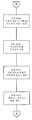
도 10a 내지 10c는 본 발명의 다양한 실시예들에 따른 문서 일부에 캡처된 이미지를 매치시키는 방법을 설명하는 순서도를 예시한 도면.10A-10C illustrate a flow chart illustrating a method of matching a captured image to a portion of a document in accordance with various embodiments of the present invention.
도 11 및 도 12는 도 6에 도시한 스트로크에 대한 주요(pivotal) 기준 포인트들의 결정을 예시하는 도면.11 and 12 illustrate the determination of pivotal reference points for the stroke shown in FIG. 6.
도 13 및 도 14는 캡처된 이미지가 와핑될 수 있는 방법의 예를 예시하는 도면.13 and 14 illustrate examples of how captured images may be warped.
<도면의 주요 부분에 대한 부호의 설명><Explanation of symbols for the main parts of the drawings>
903 : 이미지 수신 모듈903: Image receiving module
905 : 세그먼테이션 모듈905: segmentation module
907 : 세그먼트 완성 모듈907: Segment Completion Module
909 : 결과 프루닝 모듈909: Result Pruning Module
본 발명은 이미지로 캡처된 문서의 일부의 위치를 결정하는 것과 관련된다. 본 발명의 다양한 형태들은 특히, 문서의 이미지들을 캡처링함으로써 문서 상의 마크의 위치를 식별하는데 적용할 수 있다.The present invention relates to determining the location of a portion of a document captured as an image. Various aspects of the present invention are particularly applicable to identifying the position of a mark on a document by capturing images of the document.
컴퓨터 상에 저장된 전자 문서들이 기록된 문서들 이상의 많은 장점들을 가지고 있지만, 많은 사용자들은 전자 문서들의 인쇄 버전으로 몇몇 업무를 수행하고 있다. 이들 업무는, 예를 들어, 문서의 판독 및 주석 달기(annotating)를 포함한다. 주석에 있어서, 문서의 페이퍼 버전은, 주석이 통상적으로 사용자에 의해 인쇄된 문서 상에 직접 기록되기 때문에 특히 중요하다고 생각된다. 그러나, 문서의 인쇄된 버전을 직접 주석다는 데 있어서의 문제점들 중 하나는 이후에 이 주석을 전자 형태로 변환하는 어려움에 있다. 이상적으로, 전자적으로 저장된 주석은, 수기록된(handwritten) 주석이 문서의 페이퍼 버전과 일치(correspondence)하는 것과 같은 방식으로 문서의 전자 버전과 일치하여야 한다.Although electronic documents stored on a computer have many advantages over recorded documents, many users perform some tasks with printed versions of electronic documents. These tasks include, for example, reading and annotating documents. In annotations, the paper version of the document is considered particularly important because the annotations are typically recorded directly on the document printed by the user. However, one of the problems with directly annotating a printed version of a document is the difficulty of later converting this annotation to electronic form. Ideally, an electronically stored comment should match the electronic version of the document in such a way that the handwritten comment matches the paper version of the document.
이러한 일치는 일반적으로 최초 또는 다른 사용자가 주석을 달아나가고 개인적으로 이를 컴퓨터에 입력할 것을 요구한다. 몇몇 경우에, 사용자는 종이 문서 상에 기록된 주석을 전자적으로 스캔할 수 있어, 새로운 전자 문서를 생성한다. 이들 여러 단계들은 문서의 인쇄된 버전과 문서의 전자 버전 사이의 일치(reconciliation)를 반복하여 처리하는 것을 어렵게 한다. 또한, 스캔된 이미지들은 종종 편집되지 않을 수 있다. 따라서, 문서의 원문에서 주석을 분리할 방법이 없을 수 있다. 이것은 주석의 사용을 어렵게 한다.This match usually requires the first or other user to comment out and enter it personally into the computer. In some cases, a user can electronically scan annotations recorded on a paper document, creating a new electronic document. These various steps make it difficult to repeatedly process the reconciliation between the printed version of the document and the electronic version of the document. In addition, scanned images may often not be edited. Thus, there may be no way to separate comments from the original text of the document. This makes the use of comments difficult.
이 문제를 처리하기 위해서, 펜이 개발되어 인쇄된 문서 상에 기록된 주석을 펜으로 캡처한다. 이런 타입의 펜은, 사용자가 주석을 기록함에 따라 인쇄된 문서의 이미지를 캡처하는 카메라를 포함한다. 그러나, 이런 타입의 펜의 몇몇 예들은 카메라에 보이지 않는 잉크를 사용할 수 있다. 예를 들면, 이 펜은 논카본(non-carbon) 잉크 및 카메라용 적외선 조명을 사용할 수 있는데, 이는, 카메라가 잉크로 기록된 주석을 "보지" 못하다록 한다. 이런 타입의 펜을 사용하여, 펜은 주석을 기록하는 동안 펜에 의해 캡처된 이미지들에서 문서 상의 주석을 형성하는 펜 팁의 움직임을 추정할 것이다. 그러나, 이미지들을 원본 전자 문서와 관련시키기 위해서는, 문서에 관한 이미지들의 위치가 결정되어야 한다. 따라서, 이런 타입의 펜은 종종 페이퍼 상의 다른 위치들을 유일하게 식별하는 패턴을 포함하는 페이퍼와 함께 사용된다. 이 패턴을 분석함으로써, 이미지를 수신하는 컴퓨터는 페이퍼의 어느 부분(따라서 인쇄된 문서의 어느 부분)이 이미지 내에 캡처되었는지를 결정할 수 있다.To address this problem, a pen has been developed to capture annotations recorded on printed documents with the pen. This type of pen includes a camera that captures an image of the printed document as the user records the annotation. However, some examples of this type of pen may use ink that is not visible to the camera. For example, the pen can use non-carbon ink and infrared illumination for the camera, which prevents the camera from "seeing" the ink written notes. Using this type of pen, the pen will estimate the movement of the pen tip forming the annotation on the document in the images captured by the pen while recording the annotation. However, to associate the images with the original electronic document, the location of the images relative to the document must be determined. Thus, this type of pen is often used with paper containing a pattern that uniquely identifies other locations on the paper. By analyzing this pattern, the computer receiving the image can determine which part of the paper (and therefore which part of the printed document) was captured within the image.
이렇게 패턴화된 페이퍼 또는 다른 매체의 사용은, 페이퍼 문서 상의 기록된 주석이 전자 형태(form)로 변환되게 하고 문서의 전자 버전과 적절히 관련되게 하지만, 이 기술을 항상 신뢰할 수 있는 것은 아니다. 예를 들면, 페이퍼 상의 텍스트를 포함하는 문서는 패턴 영역을 불명료하게(obscure) 할 수 있다. 펜이 이들 영역들 중 하나의 이미지를 캡처한다면, 컴퓨터는 이 이미지에 의해 캡처된 문서 부분의 위치를 정확하게 결정하는데 이 패턴을 사용할 수 없을 것이다. 대신에, 컴퓨터는 이 이미지 내에 캡처된 문서 부분의 위치를 식별하기 위해서 대체 기술을 사용하여야 한다. 예를 들어, 컴퓨터는 전자 문서와 캡처된 이미지의 픽셀 단위 비교(pixel by pixel comparison)를 실행할 수 있다.The use of such patterned paper or other media allows recorded annotations on a paper document to be converted to an electronic form and properly associated with the electronic version of the document, but this technique is not always reliable. For example, a document containing text on a paper can obscure the pattern area. If the pen captures an image of one of these areas, the computer will not be able to use this pattern to accurately determine the location of the document portion captured by this image. Instead, the computer must use an alternative technique to identify the location of the document part captured in this image. For example, the computer can perform pixel by pixel comparison of the electronic document and the captured image.
픽셀 단위 비교는 일반적으로 캡처된 이미지 내의 문서의 일부를 식별할 것이지만, 이 기술은 높은 처리 부하를 갖는다. 이 기술을 실행하기 위해서는, 캡처된 이미지가 와핑(warp)되게 하고 문서 이미지와 픽셀 단위로 매치될 수 있도록, 예를 들어, 캡처된 이미지와 문서 이미지 사이의 이를테면, 회전(rotation) 및 스케일(scale)의 변환이 먼저 추정되어야 한다. 이 변환이 공지되지 않으면, 모든 가능한 회전들 및 스케일들이 고려되어야 한다. 부가적으로, 이미지 내의 기준 픽셀이 선택된다. 이후에 와핑된 이미지 내의 모든 픽셀들은, 이미지 기준 픽셀이 전자 문서 내의 제1 위치와 비교되도록 전자 문서 내의 대응 픽셀과 비교된다. 이 비교는, 기준 픽셀이 전자 문서 내의 각 위치와 최종적으로 비교되도록 반복되어야 한다. 이미지 픽셀들과 전자 문서 간의 최고 일치와의 비교는 전자 문서에 대한 기준 픽셀의 위치를 식별하여, 이미지 내에 캡처된 문서의 일부를 식별한다. 따라서, 이미지와 전체 문서 간의 픽셀 단위 비교를 수행할 필요 없이 캡처된 이미지 내의 문서 일부의 위치를 컴퓨터가 결정할 수 있는 기술을 제공하는 것이 바람직하다.Pixel by pixel comparison will generally identify a portion of the document in the captured image, but this technique has a high processing load. In order to implement this technique, the captured image can be warped and matched with the document image on a pixel-by-pixel basis, such as, for example, rotation and scale between the captured image and the document image. ) Must be estimated first. If this transformation is not known, all possible rotations and scales should be considered. In addition, the reference pixel in the image is selected. All pixels in the warped image are then compared with corresponding pixels in the electronic document such that the image reference pixel is compared with the first location in the electronic document. This comparison must be repeated so that the reference pixel is finally compared with each position in the electronic document. The comparison of the best match between the image pixels and the electronic document identifies the location of the reference pixel relative to the electronic document, thereby identifying the portion of the document captured in the image. Accordingly, it would be desirable to provide a technique that allows a computer to determine the location of a portion of a document in a captured image without having to perform pixel-by-pixel comparisons between the image and the entire document.
유리하게, 본 발명의 다양한 실시예들은 캡처된 이미지에 대응하는 문서의 일부를 결정하기 위한 효율적인 기술을 제공한다. 본 발명의 다양한 실시예들에 따르면, 사용자가 문서 내의 스트로크를 생성하는데 펜을 사용할 경우, 펜에 탑재된 카메라가 일련의 이미지들을 캡처한다. 몇몇 이미지들의 위치는, 예를 들면, 이미지에 의해 캡처된 문서상의 패턴 또는 이미지와 문서 간의 픽셀 단위 비교의 분석으로부터 결정될 것이다. 그러나, 다른 이미지들의 위치는 다른 기술들을 사용하여 결정될 필요가 있을 것이다.Advantageously, various embodiments of the present invention provide an efficient technique for determining a portion of a document corresponding to a captured image. According to various embodiments of the present invention, when a user uses a pen to generate a stroke in a document, a camera mounted on the pen captures a series of images. The location of some images will be determined, for example, from a pattern on the document captured by the image or from an analysis of the pixel-by-pixel comparison between the image and the document. However, the location of other images may need to be determined using other techniques.
위치 미지정 이미지들의 위치를 효율적으로 결정하기 위해서, 이미지들의 전체 시퀀스는 스트로크의 형태에 따른 그룹들로 분할된다. 이러한 방식으로, 스트로크의 상대적으로 선형부에 대응하는 이미지들이 함께 그룹화될 것이다. 또한, 하나의 세그먼트 내의 모든 이미지들은 통상적으로 근접하기 때문에, 하나의 세그먼트 내에 위치 지정된 이미지들에 대한 정보는 그 세그먼트 내의 위치 지정되지 않은 이미지들의 위치를 결정하는 데 사용될 수 있다. 예를 들면, 위치 지정되지 않은 이미지에 대한 문서 검색 영역은 이전에 위치 지정된 이미지의 위치 및 펜의 최대 또는 실제 속도에 기초하여 설정될 수 있다. 부가적으로, 위치 지정된 이미지의 회전 및 스케일(원근 변환(perspective transform)으로서 보다 정교해질 수 있는 유사 변환)은, 펜 포즈가 짧은 시간동안 크게 변화할 것이라 예상되지 않기 때문에, 위치 지정되지 않은 이미지의 회전 및 스케일의 추정으로서 사용될 수 있다. 이 추정된 회전 및 스케일은 문서 이미지의 방향(orientation) 및 스케일을 매칭시키도록 위치 지정되지 않은 이미지를 와핑하는데 사용될 수 있다. 이후, 와핑된 위치 지정되지 않은 이미지와 문서 검색 영역 사이에서 픽셀 단위 비교가 행해질 수 있다.In order to efficiently determine the position of the unpositioned images, the entire sequence of images is divided into groups according to the shape of the stroke. In this way, the images corresponding to the relatively linear portions of the strokes will be grouped together. Also, because all images in one segment are typically close, information about images positioned within one segment can be used to determine the location of unpositioned images within that segment. For example, the document search area for an unpositioned image may be set based on the position of the previously positioned image and the maximum or actual speed of the pen. Additionally, the rotation and scale of the positioned image (similar transformation, which can be refined as a perspective transform), is not expected because the pen pose is not expected to change significantly in a short time. It can be used as an estimate of rotation and scale. This estimated rotation and scale can be used to warp the unpositioned image to match the orientation and scale of the document image. A pixel-by-pixel comparison can then be made between the warped unpositioned image and the document search area.
오퍼레이팅 환경Operating environment
도 1은 본 발명의 다양한 양상들을 구현하는데 사용될 수 있는 종래의 범용 디지털 컴퓨팅 환경의 예의 기능적 블럭도를 도시한다. 도 1에서, 컴퓨터(100)는 프로세싱 유닛(100), 시스템 메모리(120), 및 시스템 메모리를 포함하는 다양한 시 스템 컴포넌트들이 프로세싱 유닛(110)에 결합된 시스템 버스(130)를 포함한다. 시스템 버스(130)는, 메모리 버스 또는 메모리 컨트롤러, 주변 버스, 및 다양한 버스 아키텍처들 중 임의의 아키텍처를 사용하는 로컬 버스를 포함하는 여러 타입의 버스 구조들 중 임의의 구조일 수 있다. 시스템 메모리(120)는 판독 전용 메모리(ROM)(140) 및 랜덤 액세스 메모리(RAM)(150)를 포함한다.1 illustrates a functional block diagram of an example of a conventional general-purpose digital computing environment that may be used to implement various aspects of the present invention. In FIG. 1,
시동(start up)중에서와 같이, 컴퓨터(100) 내의 구성 요소들 사이의 정보를 전달하는 것을 도와주는 기본 루틴을 포함하는 기본 입출력 시스템(BIOS; 160)이 ROM(140) 내에 저장된다. 컴퓨터(100)는 또한, (도시되지 않은) 하드 디스크로부터 판독하고 이 하드 디스크에 기록하기 위한 하드 디스크 드라이브(170), 분리가능 자기 디스크(190)로부터 판독하거나 이 자기 디스크에 기록하기 위한 자기 디스크 드라이브(180), 및 CD ROM 또는 다른 광 매체와 같은 분리가능 광 디스크(192)로부터 판독하거나 이 광 디스크에 기록하기 위한 광 디스크 드라이브(191)를 포함한다. 하드 디스크 드라이브(170), 자기 디스크 드라이브(180), 및 광 디스크 드라이브(191)는 하드 디스크 드라이브 인터페이스(192), 자기 디스크 드라이브 인터페이스(193), 및 광 디스크 드라이브 인터페이스(194)에 의해 각각 시스템 버스(130)에 접속된다. 드라이브들과 이들과 관련된 컴퓨터 판독가능 매체는 개인 컴퓨터(100)에 대한 컴퓨터 판독 가능 명령들, 데이터 구조들, 프로그램 모듈 및 다른 데이터의 비휘발성 저장소를 제공한다. 당업자라면, 자기 카세트, 플래시 메모리 카드, 디지털 비디오 디스크, 베르누이 카트리지, RAM, ROM 등과 같이 컴퓨터에 의해 액세스가능한 데이터를 저장할 수 있는 다른 타입의 컴퓨터 판독 가능 매체가 예시적인 오퍼레이팅 환경에서 또한 사용될 수 있다는 것을 알 수 있을 것이다.As during startup, a basic input / output system (BIOS) 160 is stored in
다수의 프로그램 모듈들은, 오퍼레이팅 시스템(195), 하나 이상의 애플리케이션 프로그램들(196), 다른 프로그램 모듈(197), 및 프로그램 데이터(198)를 포함하는, 하드 디스크 드라이브(170), 자기 디스크(190), 광 디스크(192), ROM(140) 또는 RAM(150) 상에 저장될 수 있다. 사용자는 키보드(101) 및 포인팅 디바이스(102)와 같은 입력 디바이스들을 통해 컴퓨터(100) 내에 명령들과 정보를 입력할 수 있다. (도시되지 않은) 다른 입력 디바이스들은 마이크로폰, 조이스틱, 게임 패드, 위성 접시, 스캐너 등을 포함할 수 있다. 이들 및 다른 입력 디바이스들은 종종 시스템 버스에 결합된 직렬 포트 인터페이스(106)를 통해 프로세싱 유닛(110)에 접속되지만, 병렬 포트, 게임 포트 또는 유니버설 시리얼 버스(USB)와 같은 다른 인터페이스에 의해 접속될 수 있다. 또한, 이들 디바이스들은 (도시되지 않은) 적절한 인터페이스를 통해 시스템 버스(130)와 직접 결합될 수 있다. 모니터(107) 또는 다른 타입의 디스플레이 디바이스도, 비디오 어댑터(108)와 같은 인터페이스를 통해 시스템 버스(130)에 접속된다. 모니터 외에, 개인 컴퓨터들은 통상적으로, 스피커 및 프린터와 같은 (도시되지 않은) 주변 출력 디바이스들을 포함한다. 바람직한 실시예에서, 펜 디지타이저(165) 및 부속의 펜 또는 스타일러스(166)는 수기 입력(freehand input)을 디지털적으로 캡처하기 위해서 제공된다. 펜 디지타이저(165)와 직렬 포트 사이의 직접 접속이 도시되었다고 해도, 실제로, 펜 디지타이저(165)는 공지된 바와 같이, 병렬 포트 또는 다른 인터페이스 및 시스템 버스(130)를 통해 프로세싱 유닛(110)과 결합될 수 있다. 또한, 디지타이저(165)가 모니터(107)와 떨어져 도시된다고 해도, 디지타이저의 사용가능한 입력 영역이 모니터(107)의 디스플레이 영역과 함께 넓어지는 것이 바람직하다. 또한, 디지타이저(165)는 모니터(107) 내에 통합되거나, 모니터(107)를 오버레이하거나 그렇지 않으면 모니터에 추가된 분리형 디바이스로서 존재할 수 있다.A number of program modules include
컴퓨터(100)는 원격 컴퓨터(109) 등의 하나 이상의 원격 컴퓨터들로의 논리 접속들을 이용해 네트워크화된 환경에서 작동할 수 있다. 원격 컴퓨터(109)는 서버, 라우터, 네트워크 PC, 동등 장치 또는 그밖의 공통 네트워크 노드가 될 수 있고, 비록 도 1에는 메모리 저장 장치(111)만이 도시되어 있으나, 컴퓨터(100)에 대하여 앞서 설명한 구성 요소들의 다수 또는 모두를 전형적으로는 포함한다. 도 1에 도시된 논리 접속들은 근거리 통신망(LAN)(112) 및 광역 통신망(WAN)(113)을 포함한다. 이런 네트워킹 환경은 사무실, 기업 전체의(enterprise-wide) 컴퓨터 네트워크, 인트라넷, 및 인터넷에서 자주 볼 수 있다.
LAN 네트워킹 환경에서 사용될 때, 컴퓨터(100)는 네트워크 인터페이스 또는 어댑터(114)를 통해서 근거리 통신망(112)에 접속된다. WAN 네트워킹 환경에서 사용될 때, 개인용 컴퓨터(100)는 인터넷 등의 광역 통신망(113) 상에서 통신을 확립하기 위한 모뎀(115) 또는 그밖의 수단을 전형적으로는 포함한다. 내부에 또는 외부에 장착될 수 있는 모뎀(115)은 직렬 포트 인터페이스(106)을 통해서 시스템 버스(130)에 접속된다. 네트워크화된 환경에서, 개인용 컴퓨터(100)에 대해 서술된프로그램 모듈들 또는 이것의 일부분들이 원격 메모리 저장 장치에 저장될 수 있다.When used in a LAN networking environment, the
도시된 네트워크 접속들은 예시적인 것이고, 컴퓨터들 간의 통신 링크를 확립하기 위한 그밖의 기술들이 사용될 수 있다. TCP/IP, Ethernet, FTP, HTTP, 블루투스(Bluetooth), IEEE 802.11x 등의 여러 공지된 프로토콜 중의 임의의 것의 존재가 가정되고, 본 시스템은 사용자가 웹 기반 서버로부터 웹 페이지들을 검색하도록 허용해 주는 클라이언트 서버 구조에서 작동할 수 있다. 다양한 종래의 웹 브라우저 중의 임의의 것이 웹 페이지 상에서 데이터를 디스플레이하고 조작하는 데에 사용될 수 있다.The network connections shown are exemplary and other techniques for establishing a communication link between the computers can be used. The presence of any of a number of known protocols such as TCP / IP, Ethernet, FTP, HTTP, Bluetooth, IEEE 802.11x, etc. is assumed, and the system allows a user to retrieve web pages from a web based server. Can work in a client server architecture. Any of a variety of conventional web browsers can be used to display and manipulate data on web pages.
이미지 캡처링 장치Image capturing device
본 발명의 여러 실시예들이 일련의 이미지들에 의해 캡처된 문서의 부분들의 위치들을 결정하는 데에 사용될 수 있다. 앞서 지적한 대로, 이미지 내에 캡처된 문서의 한 부분의 위치의 결정은, 종이, 디스플레이 스크린, 또는 문서를 디스플레이하는 그밖의 매체와 사용자의 상호작용의 위치를 확인하는 데에 사용될 수 있다. 본 발명의 몇몇 실시예에 따르면, 이 이미지들은 종이 위에 잉크로 쓰는 데에 사용되는 잉크 펜에 의해 획득될 수 있다. 본 발명의 그밖의 실시예에서는, 이 펜은 문서를 디스플레이하는 디지타이저의 표면 위에 전자적 잉크로 '필기' 하는 데에 쓰이는 스타일러스일 수 있다.Various embodiments of the present invention can be used to determine the positions of portions of a document captured by a series of images. As pointed out above, the determination of the location of a portion of the document captured in the image can be used to identify the location of the user's interaction with paper, a display screen, or other media displaying the document. According to some embodiments of the invention, these images can be obtained by an ink pen used for writing with ink on paper. In other embodiments of the present invention, the pen may be a stylus used to 'write' with electronic ink on the surface of the digitizer displaying the document.
도 2a 및 도 2b는 본 발명의 여러 실시예에 따라서 채택될 수 있는 펜(201)의 예시를 보여준다. 펜(201)은 팁(202) 및 카메라(203)를 포함한다. 팁(202)은 잉크 통을 포함하거나 포함하지 않을 수 있다. 카메라(203)는 표면(207)으로부터 이미지(204)를 캡처한다. 펜(201)은, 파선 박스(206) 내 표시된 바와 같이, 추가의 센서들 및/또는 프로세서들을 포함할 수 있다. 이런 센서들 및/또는 프로세서들(206)은 (예로, 블루투스 또는 그밖의 무선 프로토콜들을 통해) 또다른 펜(201) 및/또는 개인용 컴퓨터에 정보를 전송하는 기능을 가질 수 있다.2A and 2B show examples of
도 2b는 카메라(203)에 의해 보여지는 이미지를 나타낸다. 예시적 일례에서, 카메라(203)에 의해 캡처된 이미지의 해상도는 N×N 픽셀(여기서는 일례로 N=32) 이다. 따라서, 도 2b는 가로 32픽셀이고 세로 32픽셀인 예시적 이미지를 도시한다. N의 크기는 조정가능한데, N의 값이 높을수록 더 높은 해상도를 제공하게 된다. 또한, 카메라(203)에 의해 캡처되는 이미지가 여기서는 예시적인 목적을 위해 정방형으로 도시되었지만, 카메라의 시계(field of view)는 공지된 대로 그밖의 형태를 취할 수 있다.2B shows the image seen by the
카메라(203)에 의해 캡처된 이미지들은 이미지 프레임 시퀀스 {Ii}로서 정의될 수 있는데, 여기서, Ii는 샘플링 시간 ti에서 펜(201)에 의해 캡처된 것이다. 샘플링 레이트는 시스템 구성 및 성능 요건에 따라서 크거나 작을 수 있다. 캡처된 이미지 프레임의 크기는 시스템 구성 및 성능 요건에 따라서 크거나 작을 수 있다. 또한, 카메라(203)에 의해 캡처된 이미지는 프로세싱 시스템에 의해 직접적으로 사용되거나 또는 사전 필터링(pre-filtering)을 거칠 수 있다는 점이 인식되어야 한다. 사전 필터링은 펜(201)에서 일어나거나 또는 펜(201)의 외부에서 (예를 들면, 개인용 컴퓨터에서) 일어날 수 있다.Images captured by
도 2a는 위치(204)로부터의 패턴 이미지(210)가 그 위에 형성되는 이미지 평면(209)을 도시한다. 객체 평면(207) 상의 패턴으로부터 수신된 광은 렌즈(208)에 의해 초점이 맞춰진다. 본 발명의 여러 실시예들에 따르면, 렌즈(208)는 단일 렌즈 또는 다중부(multi-part) 렌즈 시스템일 수 있는데, 여기서는 단순화를 기하기 위해 단일 렌즈인 것으로 표시되었다. 이미지 캡처 센서(211)는 이미지(210)를 캡처한다.2A shows an
이미지 센서(211)는 이미지(210)를 캡처하는 데에 충분한 크기일 수 있다. 대안적으로, 이미지 센서(211)는 위치(212)에서 펜 팁(202)의 이미지를 캡처하는 데에 충분한 크기일 수 있다. 참조를 위해, 위치(212)에서의 이미지는 '가상 펜 팁'으로 지칭될 것이다. 이미지 센서(211)에 관한 가상 펜 팁 위치는, 펜 팁, 렌즈들(208) 및 이미지 센서(211) 사이의 일정한 관계로 인해 고정된다는 점을 유의한다.The
앞서 지적한 대로, 펜(201)은 종이 상에 인쇄된 문서 등의 매체와 함께 전형적으로는 사용되고, 매체 상의 위치들을 식별하기 위한 패턴을 디스플레이한다. 유리하게는, 이 패턴은 카메라(203)에 의해 캡처된 이미지(210)를 매체의 외관에 대응하는 형태로 변환하는 데에 사용된다. 예를 들어, 이하의 변환 함수FS→P는 카메라(203)에 의해 캡처된 이미지(210)를 한 장의 종이 상에서 실제 이미지로 변환시킨다:As noted above, the
LLpaperpaper= F= FS→PS → P (L (Lsensorsensor))
필기 동안에 펜 팁 및 종이는 동일 평면 상에 있다. 따라서, 가상 펜 팁으로부터 실제 펜 팁으로의 변환도FS→P 이다:The pen tip and the paper are on the same plane during writing. Thus, the conversion from the virtual pen tip to the actual pen tip is alsoFS → P :
LLpentippentip= F= FS→PS → P (L (Lvirtual-pentipvirtual-pentip))
이 변환FS→P 은 유사(affine) 변환으로 추정될 수 있다. 이는FS→P의 추정치로서 다음과 같이 단순화된다:This transformFS → P can be estimated as an affine transform. This is an estimate ofFS → P and is simplified as follows:

여기서,θx, θy, sx,및 sy는 위치(204)에서 캡처된 패턴의 두개의 방향의 회전량 및 스케일에 해당된다. 또한, 캡처된 이미지를 종이 상의 대응하는 실제 이미지와 매칭시킴으로써F'S→P 를 정교화할 수 있다. '정교화(refine)'는, 반복(recursive) 방법이라고 불리는 일종의 최적화 알고리즘에 의해 변환FS→P의 더 정확한 추정치를 획득하는 것을 의미한다. 이 반복 방법은 매트릭스F'S→P 를 초기치로서 취급한다. 이 정교화 추정치는 S 와 P 사이의 변환을 더 정확하게 기술한다.Here,θx , θy , sx , andsy correspond to the amount and scale of rotation in two directions of the pattern captured at
가상 펜 팁의 위치는 교정(claibration)에 의해 더욱 추가적으로 정밀하게 결정될 수 있다. 가상 펜 팁의 위치를 교정하기 위해서, 사용자는 종이 위의 고정 위치Lpentip상에 펜 팁(202)을 배치시킨다. 다음으로, 사용자는 펜을 기울여서 카메라(203)가 다른 펜 포즈들로 일련의 이미지를 캡처하도록 하여 준다. 각각의 캡처된 이미지에 대해, 변환FS→P 이 획득된다. 이 변환으로부터, 가상 펜 팁의 위치Lvirtual- pentip를 획득할 수 있다:The position of the virtual pen tip can be determined more precisely by calibration. To correct the position of the virtual pen tip, the user places the
LLvirtual- pentipvirtual- pentip = F = FP→SP → S (L (Lpentippentip))
여기서, Lpentip은 (0,0)으로 초기화되고,WhereLpentip is initialized to (0,0),
FP→S = (FS→P )-1 이다.FP → S= (FS → P )-1 .
각각의 이미지로부터 획득된Lvirtual- pentip를 평균화함으로써, 가상 펜 팁의 위치Lvirtual- pentip가 결정될 수 있다.Lvirtual- pentip 에 의해서, Lpentip의 더 정확한 추정치를 얻을 수 있다. 몇 번의 반복 후에, 가상 펜 팁의 정확한 위치Lpentip가 결정될 수 있다.By averaging theLvirtual- pentip obtained from each image, it may be determined that the virtual pen tip locationLvirtual- pentip.By using Lvirtual-pentip , a more accurate estimate ofLpentip can be obtained. After several iterations, the exact locationLpentip of the virtual pen tip can be determined.
매체 상의 위치들을 식별하기 위한 패턴Pattern for Identifying Locations on Media
앞서 지적한 대로, 본 발명의 여러 실시예들은 캡처된 이미지에 대응하는 문서의 부분을 결정하는 데에 사용될 수 있는데, 여기서 이 문서를 디스플레이하는 매체는 매체 상의 다른 위치들을 식별하기 위한 패턴을 또한 포함한다. 따라서, 이 패턴은 디스플레이된 형태의 인코딩된 데이터 스트림인 것으로 간주될 수 있다. 이 패턴을 디스플레이하는 매체는 인쇄된 종이(또는 그밖의 물리적 매체)이거나, 또는 인코딩된 데이터 스트림을 또다른 이미지 또는 이미지 세트들과 관련되어 투사하는 디스플레이일 수 있다. 예를 들어, 인코딩된 데이터 스트림은 종이 상의 물리적 이미지 또는 디스플레이된 이미지 위에 겹치는 이미지로서 표현될 수 있거나, 또는 (펜에 의해 캡처되는 임의의 이미지 부분이 디스플레이 스크린 상에 위치할 수 있도록) 디스플레이 스크린과 결합된 또는 이 스크린 위에 겹치는 물리적 인코딩된 패턴(즉, 수정 불가능한 패턴)이 될 수 있다.As noted above, various embodiments of the present invention can be used to determine a portion of a document corresponding to a captured image, wherein the medium displaying the document also includes a pattern for identifying other locations on the medium. . Thus, this pattern can be considered to be an encoded data stream in the displayed form. The medium displaying this pattern can be printed paper (or other physical medium) or a display projecting the encoded data stream in association with another image or set of images. For example, the encoded data stream can be represented as a physical image on paper or an image superimposed on the displayed image, or with a display screen (so that any portion of the image captured by the pen can be placed on the display screen). It may be a physically encoded pattern (ie, an unmodifiable pattern) that is combined or overlaps on this screen.
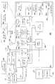
도 3a는 제1 비트 및 제2 비트를 매체 상에서의 위치들을 식별하기 위한 패턴이 되도록 인코딩하는 인코딩 기법의 일례를 도시한다. 제1 비트(301)(예를 들어, "1" 값을 가짐)는 흑색 잉크 열(column)에 의해 대표된다. 제2 비트(302)(예를 들어 "0" 값을 가짐)는 흑색 잉크 행(row)에 의해 대표된다. 그러나, 임의의 색의 잉크가 여러 비트들을 표현하기 위해 사용될 수 있음을 알아야 한다. 선택된 잉크 색에 대한 유일한 요건은 이미지 캡처링 시스템이 구별할 수 있도록 매체의 배경에 대해 상당한 정도의 콘트라스트를 제공해야 한다는 점이다. 본 예시에서는, 도3a의 비트들은 3×3 도트 매트릭스로 표현된다. 이 매트릭스의 크기는 매체의 이미지들을 캡처하기 위해 사용되고 있는 이미지 캡처 시스템의 크기 및 해상도에 기초하여 바람직한 임의의 크기로 변경될 수 있다.3A shows an example of an encoding technique that encodes a first bit and a second bit to be a pattern for identifying locations on a medium. The first bit 301 (eg having a value of "1") is represented by a black ink column. The second bit 302 (eg having a value of "0") is represented by a black ink row. However, it should be appreciated that ink of any color may be used to represent the various bits. The only requirement for the selected ink color is that it must provide a significant amount of contrast to the background of the media so that the image capturing system can distinguish it. In this example, the bits of FIG. 3A are represented by a 3x3 dot matrix. The size of this matrix can be changed to any size desired based on the size and resolution of the image capture system being used to capture images of the medium.
0 과 1 값을 갖는 비트들에 대한 대안 예가 도 3c 내지 도 3e에 도시되었다. 도 3a 내지 도 3e의 샘플 인코딩들에 대한 1 또는 0의 표현은 별다른 영향 없이 스위칭될 수 있음을 알아야 한다. 도 3c는 인터리빙된 배치에서 두개의 행 또는 열을 차지하는 비트 표현들을 도시한다. 도 3d는 대시(dash) 형태의 열 및 행의 대안적 픽셀 배치를 도시한다. 최종적으로, 도 3e는 불규칙 간격 포맷(예를 들어, 두개의 흑색 도트 후에 공백 도트가 뒤따라 옴)의 열 및 행의 픽셀 표현을 도시한다.
하부에 있는 그리드(grid)의 비-수평 및 비-수직 배치로의 회전(예를 들면, 패턴의 정확한 방향이 45°인 경우)을 포함하여 대안 그리드 배치들이 가능하다는 것을 인식해야 한다. 비-수평 및 수직 배치를 이용하면, 사용자의 시각 혼선을 제거는 예상되는 이득을 얻을 수 있는데, 이는 사용자들이 다른 것들보다 수평 및 수직 패턴들을 알아차리는 경향이 있기 때문이다. 그러나, 단순화를 위해, 그리드의 방향(하부에 있는 그리드의 수평, 수직 및 바람직한 임의의 다른 방향)은 소정 그리드 방향이라고 총칭된다.An alternative example for bits with 0 and 1 values is shown in FIGS. 3C-3E. It should be noted that the representation of 1 or 0 for the sample encodings of FIGS. 3A-3E can be switched without much effect. 3C shows the bit representations occupying two rows or columns in an interleaved arrangement. 3D shows an alternative pixel arrangement of columns and rows in the form of dashes. Finally, FIG. 3E shows pixel representations of columns and rows in an irregularly spaced format (eg, two black dots followed by a blank dot).
It should be appreciated that alternative grid arrangements are possible, including rotation of the underlying grid into non-horizontal and non-vertical arrangements (eg, when the exact direction of the pattern is 45 °). Using non-horizontal and vertical placement, eliminating the user's visual confusion can yield the expected benefit, since users tend to notice horizontal and vertical patterns more than others. However, for the sake of simplicity, the direction of the grid (horizontal, vertical and any other desired direction of the grid at the bottom) is collectively referred to as the desired grid direction.
삭제delete
도 3a를 다시 참조하면, 비트가 3 × 3 소자 매트릭스에 의해 표현되고 촬상 시스템이 3 × 3 영역에서 1개의 흑색 행과 2개의 백색 행을 검출하는 경우, 이 영역은 0의 값(대안적으로는 1의 값)으로 검출된다. 3 × 3 영역이 흑색 열과 2개의 백색 열을 갖는 것으로 검출되는 경우, 이 영역은 1의 값(대안적으로는 0의 값)으로 검출된다. 따라서, 도 2b의 이미지(210)의 크기가 32 × 32 픽셀이고 각각의 인코딩 단위 크기가 3 × 3 픽셀이라면, 캡처 및 인코딩된 단위들의 수는 대략 100 단위가 되어야 한다. 만일 인코딩된 단위 크기가 5×5 라면 캡처 및 인코딩된 단위들의 수는 대략 36이 되어야 한다.Referring again to FIG. 3A, where the bits are represented by a 3 × 3 element matrix and the imaging system detects one black row and two white rows in the 3 × 3 region, this region is a value of zero (alternatively). Is a value of 1). When it is detected that the 3x3 area has a black column and two white columns, this area is detected with a value of 1 (alternatively, a value of 0). Thus, if the size of the
도 3a에 도시된 대로, 하나 이상의 픽셀 또는 도트가 일 비트를 나타내는 데에 사용될 수 있다. 일 비트를 나타내기 위해 단일 픽셀(또는 도트)를 사용하는 것은 신뢰성이 없다. 먼지, 종이의 주름, 비평탄 표면 등이 데이터 단위들의 단일 소자 표현을 판독하는 데에 어려움을 야기한다. 그러나, 비트를 표현하기 위해 다중 소자들을 사용하더라도, 문서 내 타이핑된 텍스트와 같이, 매체 상에 디스플레이된 패턴을 가지는 그 밖의 텍스트는 여전히 패턴 내의 하나 이상의 비트를 불명료하게 할 수 있다.As shown in FIG. 3A, one or more pixels or dots may be used to represent one bit. Using a single pixel (or dot) to represent one bit is not reliable. Dirt, wrinkles on paper, uneven surfaces, etc. cause difficulty in reading a single element representation of data units. However, even if multiple elements are used to represent the bits, other text with a pattern displayed on the medium, such as typed text in a document, can still obscure one or more bits in the pattern.
도 3b의 그래픽 패턴(303)을 생성하기 위해 비트 스트림이 이용된다. 그래픽 패턴(303)은 12행과 18열을 포함한다. 더 구체적으로, 행과 열은 비트 표현(301, 302)을 이용하여, 그래픽 패턴(303)으로 변환되는 비트 스트림에 의해 형성된다. 따라서, 도 3b의 패턴(303)은 다음의 비트 표현을 갖는 것으로 도시될 수 있다.The bit stream is used to generate the

도 3b에 도시된 이미지(303)를 생성하기 위해 다양한 비트 스트림들이 이용될 수 있다. 예를 들어, 1들과 0들의 랜덤 또는 의사-랜덤(pseudo-random) 시퀀스가 이용될 수 있다. 비트 시퀀스는 행들로, 열들로, 대각선으로, 혹은 임의의 다른 형식적 정렬에 따라 배열될 수 있다. 예를 들어, 좌로부터 우로 나아가고 이후 아래로 진행하는 경우, 상기 매트릭스는 다음과 같은 비트 스트림에 의해 형성될 수 있다.Various bit streams may be used to generate the
0100 0111 0110 0100 1000 1110 0111 0100 11000100 0111 0110 0100 1000 1110 0111 0100 1100
위에서부터 아래로 나아가고 이후 우로 진행하는 경우, 상기 매트릭스는 다음과 같은 비트 스트림에 의해 형성될 수 있다.When going from top to bottom and then to right, the matrix may be formed by the following bit stream.
0101 1100 0011 0010 0110 1001 1001 1110 00100101 1100 0011 0010 0110 1001 1001 1110 0010
대각선으로 나아가고 이후 감싸지는(wrap) 경우, 상기 매트릭스는 다음과 같은 비트 스트림에 의해 형성될 수 있다.When going diagonally and then wrapping, the matrix can be formed by the following bit stream.
0110 0000 0101 0101 1000 0011 1111 1010 10100110 0000 0101 0101 1000 0011 1111 1010 1010
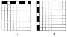
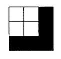
도 3b는 또한, 이미지(303)로부터의 픽셀 블럭들의 확대도들을 포함한다. 확대도(304-211)들은 5×5 픽셀 블럭들을 나타낸다. 픽셀 블럭(304)은 백색 행들 사이에 흑색 행을 나타낸다. 픽셀 블럭(305)은 백색 열들 사이에 흑색 열을 나타낸다. 픽셀 블럭(306)은 좌측 하부 코너를 나타낸다. 픽셀 블럭(307)은 우측 상부 코너를 나타낸다. 픽셀 블럭(308)은 흑색 열과 좌측 절반의 흑색 행을 나타낸다. 픽셀 블럭(309)은 흑색 행과 행 위 절반의 흑색 열을 나타낸다. 픽셀 블럭(310)은 절반의 흑색 행을 나타낸다. 픽셀 블럭(311)은 절반의 흑색 열을 나타낸다. 픽셀 블럭들의 조합을 분석하면, 픽셀들의 모든 조합들은, 픽셀 블럭들(304-311)에서 발견되는 이미지 세그먼트들에 의해 형성될 수 있음을 알 수 있다. 도 3b에 도시된 패턴의 타입은, 라인 세그먼트들이 미로에 의해 모든 사면에서 완전히 봉해지는 영역 없이 미로를 형성하기 때문에, "미로(maze)" 패턴으로 칭해질 수 있다.3B also includes magnified views of pixel blocks from
그 이상 없이, 도 3f-3i에 도시된 픽셀들의 4개의 "코너" 조합들 각각은 이미지(303)에 도시된 미로 패턴에서 발견될 수 있을 것으로 기대된다. 그러나, 도 3b에 도시된 바와 같이, 오직 3가지 타입의 코너들만 8개 픽셀 블럭들(304-311) 내에 실제로 존재한다. 이 예시에서는, 도 3f에 도시된 픽셀들의 코너 조합은 없다. 이러한 방식으로 이미지 세그먼트들(301, 302)을 선택하여 코너 타입을 제거함으로써, 캡처된 이미지의 방향이 없어진 코너 타입에 기초해 결정될 수 있다.Without further, it is expected that each of the four "corner" combinations of pixels shown in FIGS. 3F-3I can be found in the maze pattern shown in
예를 들어, 도 4에 도시된 바와 같이, 카메라(203)에 의해 캡처된 이미지(401)는 분석되고, 이미지(401)에 의해 실제로 표현된 위치에 대해 해석될 수 있도록 그 방향(orientation)이 결정될 수 있다. 첫째, 이미지(401)가 검토되어, 이미지(401)의 어떤 픽셀들이 미로 패턴을 형성하는지, 및 패턴의 픽셀들이 수평 및 수직으로 정렬되도록 이미지를 회전하는데 필요한 각도 θ를 결정할 수 있다. 상술한 바와 같이, 비-수평적 및 비-수직적 배열(예를 들면, 패턴의 정확한 방향이 45도임)로 하부의 그리드를 회전시키는 것을 포함하여, 대안적인 그리드 배열들이 본 발명의 다른 실시예들에 따라 가능함이 이해되어야 한다.For example, as shown in FIG. 4, the
그 다음, 이미지(401)는 어느 코너가 빠졌는지를 결정하기 위해 분석된다. 이미지(401)를 디코딩(403)을 위해 준비된 이미지로 회전시키는데 필요한 회전량 o가 o=(θ+ {어느 코너가 빠졌는지에 의해 결정되는} 회전량)으로 표현된다. 회전량은 도 5의 방정식으로 표현된다. 도 4를 다시 참조하면, 각도 θ는, 픽셀들의 수평 및 수직(또는 미리 정의된 다른 그리드 방향) 배열에 도달하는 픽셀들의 레이아웃에 의해 먼저 결정되고, 이미지가 402로 도시된 바와 같이 회전된다. 이후 분석이 수행되어 없어진 코너를 결정하고, 디코딩을 위한 이미지 셋업을 위해 이미지(403)로 회전되는 이미지(402)가 결정된다. 여기서, 이미지는 시계 반대 방향으로 90도 회전되어, 이미지(403)가 정확한 방향을 가지고 디코딩에 이용될 수 있다.The
회전 각도 θ는, 없어진 코너를 설명하기 위해 이미지(401)의 회전 전 또는 후에 적용될 수 있음이 이해되어야 한다. 캡처된 이미지 내의 노이즈를 고려해 4가지 코너 타입 모두가 존재할 수 있음을 알아야 한다. 따라서, 본 발명의 다양한 실시예들에 있어서, 각각의 타입의 코너들의 개수가 카운트될 수 있고, 최소 개수의 코너를 갖는 타입이 없어진 코너 타입인 것으로 결정될 수 있다.It should be understood that the rotation angle θ can be applied before or after the rotation of the
최종적으로, 이미지(403) 내의 코드가 판독되고, 이미지(303)를 생성하기 위해 이용되는 원시 비트 스트림과 연관된다. 연관은 다수의 방식들에 의해 행해질 수 있다. 예를 들어, 복원된 비트 스트림이 원시 비트 스트림 내의 모든 다른 비트 스트림 프레그먼트들과 비교되는 재귀적 방식에 의해 수행될 수 있다. 둘째로, 예를 들면, 복원된 비트 스트림과 원시 비트 스트림 사이의 해밍 거리를 이용함으로써, 복원된 비트 스트림과 원시 비트 스트림 간에 통계적 분석이 행해질 수 있다. 원시 비트 스트림에서 복원된 비트 스트림의 위치를 결정하기 위해 다양한 방법들이 이용될 수 있음을 이해한다.Finally, the code in
이상의 설명으로부터, 상술한 미로 패턴이 예를 들면 종이나 디지타이저의 디스플레이 등의, 매체의 표면상에 정보를 인코드하는데 이용될 수 있음을 이해할 것이다. 이후, 이 정보는 펜(201)의 카메라(203)에 의해 하나 이상의 이미지들로 캡처되고, 디코딩될 수 있다. 매체의 표면 상에 인코드될 수 있는 특별히 유용한 타입의 정보는 위치 정보이다. 비트 스트림 부분들이 매체 상에서 반복되지 않으면, 컴퓨터(101)는 특정의 비트 스트림을 포함하는 문서 부분을 결정할 수 있다.From the above description, it will be appreciated that the maze pattern described above can be used to encode information on the surface of a medium, such as for example a display of paper or a digitizer. This information can then be captured and decoded into one or more images by the
패턴의 완전한 부분이 이미지로 캡처되면, 컴퓨터(101)는, 상술한 바와 같이, 이미지로 캡처된 문서 부분을 결정할 수 있을 것이다. 그러나, 어떤 상황에서는, 패턴의 일부분이 불명료할 수 있다. 예를 들어, 매체가 가령, 타이프 기록된(typewritten) 텍스트를 포함하는 문서인 경우, 텍스트는 패턴 내의 하나 이상의 비트들을 부분적으로 불명료하게 할 수 있다. 상기 예(각각의 비트는 3×3 픽셀들의 매트릭스로 구성되고, 카메라(203)의 해상도는 32×32 픽셀임)에서, 이미지로부터 60개 이상의 비트들이 식별될 수 있는 경우, 컴퓨터(101)는 이미지에서 캡처된 문서 부분의 위치를 매우 용이하게 결정할 수 있을 것이다. 그러나, 이미지에서 36 내지 60개의 비트들만이 식별될 수 있는 경우, 컴퓨터(101)는 여전히 이미지 내 캡처된 문서 부분의 위치를 결정할 수 있다. 또한, 이미지로부터 35개 이하의 비트들이 식별될 수 있는 경우, 컴퓨터(101)는 이미지 내 캡처된 문서 부분을 결정할 수 없을 것이다.Once the complete portion of the pattern is captured as an image, the
스트로크를 이용하여 캡처된 이미지들Images captured using stroke
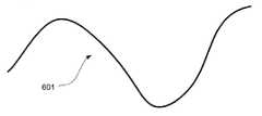
본 발명의 예시된 실시예에 있어서, 앞서 상세히 설명한 바와 같이, 문서 상에 스트로크를 형성하는 잉크는 카메라(203)에 보여지지 않는다. 그 대신, 카메라(203)는, 펜이 움직여 스트로크를 형성함에 따라 단지 문서의 이미지들을 캡처한다. 실제 펜 팁의 위치, 및 그에 따른 스트로크의 위치는, 이미지들의 중심의 위치를 캘리브레이션 파라미터로 오프셋 함으로써 추정된다. 따라서, 도 6은 펜(201)을 이용하여 문서 상에 형성될 수 있는 스트로크에 대응하는 스트로크 경로(601)의 일례를 도시한다. 스트로크 경로(601)는 스트로크의 형상을 따르지만, 스트로크로부터의 오프셋에 있다. 사용자가 펜(201)을 움직여 스트로크를 형성함에 따라, 카메라(203)는 스트로크 경로(601)를 따라 문서의 이미지를 주기적으로 캡처한다. 따라서, 도 7에 도시된 바와 같이, 카메라(203)는, 각각의 이미지의 중심이 스트로크 경로(601) 상에 들어오는, 문서의 일련의 이미지들(701A-701X)을 캡처할 것이다. 따라서, 각각의 이미지들(701A-701X)의 중심은 실제 스트로크 경로(601) 상에 들어온다. 도 8은 이미지들(701A-701X) 각각의 중심들인 일련의 포인트들(801A-801X)을 예시한다. 그러나, 본 발명의 다른 실시예들은 다른 구성을 채택할 수 있음을 이해해야 한다. 예를 들어, 본 발명의 대안적인 실시예에서는, 캡처된 이미지의 중심이 펜(201)의 실제 팁(202)에 대응할 수 있다.In the illustrated embodiment of the present invention, as described in detail above, ink forming strokes on the document is not visible to the
전술한 바와 같이, 문서는 문서의 다양한 위치들을 식별하기 위한 비트 정보를 포함하는 패턴을 포함할 것이다. 따라서, 각각의 이미지(701A-701X)는 이 패턴의 부분을 포함할 수 있다. 어떤 경우에는, 캡처된 이미지가 예를 들면 컴퓨터(101)와 같이 컴퓨터가 이미지의 위치를 결정하기에(즉, 이미지 내 캡처된 문서 부분의 위치를 결정하기에) 충분한 패턴을 포함할 것이다. 대안적으로, 하나 이상의 이미지들의 위치는, 예를 들면 이미지를 문서 혹은 문서의 선택된 영역들과 픽셀 단위 비교를 수행함으로써, 구해질 수 있다.As mentioned above, the document will include a pattern containing bit information for identifying various locations of the document. Thus, each
반면에, 앞서 살펴본 바와 같이, 이미지로부터 불충분한 개수의 비트들이 식별되면, 컴퓨터(101)는 이미지 내 문서의 어느 위치가 캡처되었는지를 결정할 수 없다. 그 대신, 컴퓨터(101)는, 이미지에서 문서의 어느 위치가 캡처되었는지를 결정하기 위한 대안적인 기술을 채택해야 한다. 문서가 전자적 형태로 저장되어 있고, 문서 이미지에 대하여 캡처된 이미지의 회전 및 스케일이 추정될 수 있다면, 컴퓨터(101)는 회전 및 스케일된 이미지 내 모든 픽셀과 전자적 문서 내의 모든 위치 간의 픽셀 단위 비교를 수행할 수 있다. 이 기술은 매우 많은 양의 비교 프로세스들을 요구할 것이다. 예를 들어, 한 페이지의 전자 문서는 1410×2019 픽셀들을 포함하므로 2,889,090 (1410×2019)회의 비교가 필요하다. 또한, 각각의 비교 프로세스는 다수의 픽셀들을 비교한다. 예를 들어, 캡처된 이미지는 32×32 픽셀들을 포함할 수 있으며, 따라서 각각의 비교는 1024 (32×32) 픽셀들을 비교한다. 또한, 캡처된 이미지의 회전 및 스케일이 추정될 수 없는 경우, 모든 가능한 회전 및 스케일이 고려되어야 한다. 따라서, 이 기술은 매우 많은 양의 프로세서 오버헤드를 수반하고 시간-소모적이다. 그 대신에, 하기에서 보다 상세히 논의되는 바와 같이, 컴퓨터(101)는 본 발명의 다양한 실시예들에 따라 로컬 고속 이미지 매치를 수행함으로써, 이미지의 위치를 보다 효과적으로 빠르게 결정할 수 있다.On the other hand, as discussed above, if an insufficient number of bits are identified from an image, the
도 9는 본 발명의 다양한 실시예들에 따라 고속 이미지 매치를 수행하기 위해 채택될 수 있는 툴(901)을 예시한다. 툴(901)은 이미지 수신 모듈(903), 세그먼테이션 모듈(905), 세그먼트 완성 모듈(907), 및 결과 프루닝(pruning) 모듈(909)을 포함한다. 하기에서 더욱 상세히 논의되는 바와 같이, 이미지 수신 모듈(903)은, 각각의 이미지의 중심이 실제 잉크 스트로크로부터 오프셋에 있는 스트로크 경로(601)에 들어오는, 물리적 매체 상에 디스플레이된 문서의 일부의 이미지를 수신한다. 세그먼테이션 모듈(905)은 이후 각각의 이미지를 분석하여, 스트로크 형상에 대응한 이미지들의 시퀀스를 분할한다. 일단 세그먼트들이 결정되면, 세그먼트 완성 모듈(907)은 세그먼트 내의 각각의 이미지의 위치를 결정함으로써 각각의 세그먼트를 "완성한다". 이후, 결과 프루닝 모듈(909)은, 세그먼트 완성 모듈(907)에 의해 에러로 결정되었던 위치 결과들을 제거한다. 도 10a 내지 10c에 도시된 순서도에는 위치 미지정 이미지들에 대응한 문서 부분들을 결정하는 한가지 방법이 설명되어 있으며, 이하에서 더욱 상세히 논의될 것이다.9 illustrates a
이미지 세그먼테이션Image segmentation
스트로크 경로를 따라 캡처된 이미지들이 분석될 때, 컴퓨터(201)는 먼저, 예를 들면 상술한 미로 패턴과 같은 문서 내에 제공된 패턴을 이용하여 각각의 이미지의 위치를 정하려고 시도할 것이다. 패턴을 디코딩함으로써 성공적으로 위치가 정해지는 이미지가 없는 경우, 제1 이미지와 문서(또는, 문서의 예상되는 대응 영역들이 식별될 수 있는 경우, 그 예상되는 대응 영역들) 사이에 픽셀 단위 비교가 수행된다. 제1 이미지가 이러한 비교에 의해 성공적으로 위치 지정될 수 있다면, 나머지 프레임들은 하기에서 보다 상세히 논의되는 로컬 위치 결정(local localization) 프로세스를 이용하여 분석된다. 제1 이미지가 성공적으로 위치 지정될 수 없는 경우, 그 다음 프레임이 픽셀 단위 비교를 이용하여 분석된다. 이 프로세스는 이미지가 성공적으로 위치 지정될 때까지, 또는 임의의 이미지들이 위치 지정될 수 없다고 판정될 때까지 계속된다. 임의의 이미지가 위치 지정될 수 없는 경우, 그 스트로크는 잃어버린 것이 된다(즉, 스트로크의 위치가 결정될 수 없다). 위치 지정된 이미지들의 중심은 이하에서는 "시작" 포인트라고 칭하는데, 그 이유는 이들 포인트들이 스트로크 경로(601)를 따라 위치 미지정 이미지들의 위치를 결정하기 위한 기준선으로 이용이기 때문이다. 따라서, 패턴을 이용해 또는 픽셀 단위 비교에 의해, 성공적으로 위치 지정된 각각의 프레임의 중심은 시작 포인트이다.When the images captured along the stroke path are analyzed, the
도 8을 다시 참조하면, 이 도면은 다양한 포인트들(801A-801X)을 도시하고, 이들 포인트들의 각각은 이미지들(701A-701X) 각각의 중심이다. 이 도면에서, 원으로 표현된 포인트들은 시작 포인트들이다. 그러므로, 포인트들(801A, 801C, 801F, 801I, 801K, 801O, 801Q, 801T, 및 801X)은 시작 포인트들이다. 별표로 나타내진 포인트들은 위치 미지정 이미지들의 중심들이다(즉,문서의 미식별 부분을 캡처한 이미지들). 그러므로, 포인트들(801B, 801D, 801E, 801G, 801H, 801J, 801L, 801M, 801N, 801P, 801R, 801S, 801U, 801V, 801W, 및 801X)은 위치 미지정 포인트들이다.Referring again to FIG. 8, this figure shows
도 10a를 참조하면, 단계(1001)에서, 이미지들의 시퀀스(또는 프레임들)가 분할된다. 더욱 구체적으로, 이미지들의 시퀀스는 그룹들로 나누어져, 각각의 그룹이 스트로크 경로(601)의 비교적 선형인 부분에 대응한다. 아래에서 더욱 상세히 논의되는 바와 같이, 이 세그먼테이션은 세그먼트의 위치 미지정 이미지들의 위치가 그 세그먼트의 위치 지정된 이미지들의 위치로부터 정확하게 보간되도록 한다. 스트로크에 대한 세그먼트들을 결정하기 위해, 세그먼테이션 모듈(903)은 스트로크에 대한 주요 시작 포인트들을 식별한다. 주요 시작 포인트들은 스트로크가 방향을 변경하는 위치 또는 근접 위치들에서 발생하는 포인트들이다. 추가로, 스트로크의 제1 및 최종 포인트들은 주요 시작 포인트들로서 고려될 것이다.Referring to FIG. 10A, in step 1001, a sequence (or frames) of images is divided. More specifically, the sequence of images is divided into groups, each group corresponding to a relatively linear portion of the
스트로크 경로(601)에 대해 이미지들(701A-701X)의 시퀀스를 분할하는 하나의 프로세스가 도 11 및 도 12에 그래프로 도시된다. 제1 시작 포인트(801A) 및 최종 시작 포인트(801X)는, 상술한 바와 같이, 주요 시작 포인트들(pivotal start points)로서 고려된다. 그러므로, 주요 시작 포인트들(801A 및 801X)은 그들 사이의 스트로크 경로(601)의 단일 세그먼트를 정의한다. 스트로크 경로(601)에 대한 추가 주요 시작 포인트들을 결정하기 위해, 도 11에 도시된 바와 같이, 세그먼테이션 모듈(903)은 제1 주요 시작 포인트(801A)와 최종 주요 시작 포인트(801X) 사이에 라인(1101)을 생성한다. 이후, 라인(1101)으로부터 가장 먼 시작 포인트(801O)(아래 설명되는 바와 같이, 0.5 픽셀 등의 임계치보다 먼 거리를 가짐)가 주요 시작 포인트로서 식별된다. 그러므로, 세그먼테이션 모듈(903)은 라인(1101)으로부터 거리 d1에 위치된 시작 포인트(801O)를 주요 시작 포인트로서 정한다. 시작 포인트(801O)를 정의하는 것은 이미지들(701A-701X)의 시퀀스를 2개의 세그먼트들로 분할한다. 제1 세그먼트 SEG1는 주요 시작 포인트(801A)와 주요 시작 포인트(801O) 간의 스트로크 경로(601) 부분에 대응하고, 제2 세그먼트 SEG2는 주요 시작 포인트(801O)와 주요 시작 포인트(801X) 간의 스트로크 경로(601) 부분에 대응한다.One process for dividing the sequence of
세그먼테이션 모듈(903)은 각각의 세그먼트가 비교적 곧은 스트로크의 부분에 대응할 때까지, 각각의 세그먼트를 더 작은 세그먼트들로 계속 분할한다. 예를 들어, 스트로크 경로(601)로, 세그먼테이션 모듈(903)은 제1 세그먼트 SEG1을 더 작은 세그먼트들로 분리할 것이다. 더 구체적으로, 세그먼테이션 모듈은 세그먼트 SEG1의 종단 포인트들 간에(즉, 주요 시작 포인트(801A)와 주요 시작 포인트(801O) 간에) 라인(1201)을 생성할 것이다. 그 다음, 세그먼테이션 모듈(903)은 라인(1201)으로부터 가장 먼 시작 포인트를 식별한다. 그러므로, 세그먼테이션 모듈(903)은, 주요 시작 포인트로서, 라인(1201)으로부터 거리 d2에 위치한 시작 포인트(801F)를 지정한다. 시작 포인트(801F)를 정의하는 것은 이미지들(701A-701O)의 세그먼트를 2개의 세그먼트들로 분할한다. 제1 세그먼트 SEG1A는 주요 시작 포인트(801A)와 주요 시작 포인트(801F) 간에 스트로크 경로(601) 부분에 대응하고, 제2 세그먼트 SEG1B는 주요 시작 포인트(801F)와 주요 시작 포인트(801O) 간의 스트로크 경로(601) 부분에 대응한다.
세그먼테이션 모듈(903)은 이미지들의 각각의 세그먼트가 거의 선형인 스트로크의 부분에 대응할 때까지 각각의 이미지들의 세그먼트의 분할을 계속한다. 예를 들어, 세그먼테이션 모듈(903)이 세그먼트를 형성하는 2개의 주요 시작 포인트들 간에 라인을 생성하고, 라인으로부터 임계 거리보다 먼 시작 포인트들이 없으면, 세그먼테이션 모듈은 세그먼트를 더 분할하지 않을 것이다. 본 발명의 일부 실시예들에서, 임계치는 문서에서 개별 위치들을 정의하기 위해 채택된 가령 0.5 유닛(예를 들면, 픽셀)의 거리일 수 있다(예를 들어, 직교좌표계를 사용함). 물론, 더 높은 임계치가 사용되어, 이미지들의 세그먼트들이 보다 적은 정도의 선형인(less linear) 스트로크 부분들에 대응하게 할 수 있다. 또한, 더 낮은 임계치가 사용되어, 이미지들의 세그먼트들이 더욱 선형인 스트로크의 부분들에 대응하게 할 수도 있다.
일단 세그먼테이션 모듈(903)이 스트로크의 모든 주요 시작 포인트들을 식별하면, 그것은 주요 시작 포인트들에 대한 위치 및 원근 변환을 정교화한다. 더 구체적으로, 세그먼테이션 모듈(903)은 주요 시작 포인트(801)에 대응하는 각각의 이미지(701)와 문서의 전자 버전을 비교하여, 주요 시작 포인트(801)의 위치 및 원근 변환을 더욱 정확히 결정한다. 이 비교 프로세스는, 예를 들어 1997년 9월 1일에 발행되고 2001년 10월에 갱신된, Heung-Yeung Shum과 Richard Szeliski에 의한, "파노라믹 이미지 모자이크(Panoramic Image Mosaics)", 마이크로소프트 리서치 기술 보고서 MSR-TR-97-23에 기재된 기술 등의 임의의 바람직한 공지 기술을 사용하여 채용될 수 있다. 주요 시작 포인트들을 정교화하는 것은 이미지들의 시퀀스를 세그먼트들로 분할하는 처리를 완료한다.Once
주요 시작 포인트(801)(및 그들과 연관된 이미지들(701))의 위치를 더욱 정확히 결정하는 것에 더하여 주요 시작 포인트(801)를 정교함으로써, 세그먼테이션 모듈(903)은 이미지들과 그들의 문서의 대응하는 부분들을 매치시키기 위해 사용되는 변환 파라미터들의 정확성을 증가시킨다. 상술한 바와 같이, 펜(201)의 경사(tilting) 및 회전(rotation)은 카메라에 의해 찍힌 이미지들이 문서의 실제 외관에 대해 회전되고 크기가 조절되도록 한다. 문서의 일부와 이미지를 정확하게 비교하기 위해, 이미지는 펜(201)의 경사와 회전에 의해 야기된 회전 및 크기의 변경을 보완하기 위해 와핑(warping)되어야 한다. 예를 들어, 도 13은 원본 이미지(1301)를 도시한다. 이후, 도 14는, 이미지가 와핑 변환 파라미터들에 따라 와핑된 후의 동일 이미지(1401)를 도시한다.In addition to more accurately determining the location of the main starting point 801 (and the images 701 associated with them), by elaborating the main starting point 801, the
주요 시작 포인트들을 문서의 전자 버전과 더 정확하게 비교하여, 세그먼테이션 모듈(903)은 문서와 매치되도록 이미지를 더 정확히 와핑하기 위해 변환 파라미터들을 수정할 수 있다. 본 발명의 다양한 실시예들에서, 세그먼테이션 모듈(903)은 시퀀스의 모든 캡처된 이미지들에 적용되는 변환 파라미터들의 단일 세트를 수정할 수 있다. 그러나, 본 발명의 다른 실시예들에서, 세그먼테이션 모듈(903)은 각각의 주요 시작 포인트에 대해 변환 파라미터들의 특정 세트를 생성한다. 아래에서 더욱 상세히 설명되는 바와 같이, 각각의 주요 시작 포인트에 대한 변환 파라미터들의 특정 세트를 갖는 것은, 인근의 위치 미지정 포인트들이 더 정확히 보간되도록 한다. 펜(201)의 경사 및 회전이 전체 스트로크의 거리에 걸쳐 매우 다양할 수 있는 한편, 펜(201)의 경사 및 회전은 통상적으로 스트로크의 단일 세그먼트의 짧은 거리에 걸쳐 그다지 다양하지 않을 것이다. 따라서, 각각의 주요 시작 포인트에 대한 변환 파라미터들은 주요 시작 포인트에 대응하는 이미지의 바로 전 또는 바로 후에 캡처된 이미지들을 더욱 정확하게 와핑하기 위해 사용될 수 있다.By comparing the key starting points more accurately with the electronic version of the document, the
세그먼테이션 모듈(903)이 이미지들(701A-701X)을 분할한 후에, 세그먼트 완성 모듈(907)은 이미지들의 각각의 세그먼트를 처리하여 각각의 세그먼트의 위치 미지정 이미지들의 위치를 결정한다. 그러므로, 단계(1003)에서, 세그먼트 완성 모듈(907)은 제1 세그먼트 내 이미지들을 수신한다. 다음, 단계(1003)에서, 세그먼트 완성 모듈(907)은 세그먼트가 완성되었는지를 결정한다. 세그먼트 완성 모듈(907)은 세그먼트가 주요 시작 포인트가 아닌 적어도 한 개의 시작 포인트를 포함하면 세그먼트가 완성되었다고 결정할 것이다. 즉, 세그먼트 내 주요 시작 포인트 이외의 적어도 한 개의 포인트의 위치가, 이미지 내 캡처된 패턴으로부터 또는 다른 기술에 의해 미리 결정되는 경우, 세그먼트는 완성된다. 이 경우, 세그먼트는 세그먼트의 모든 이미지들의 위치는 선형 보간법에 의해 결정될 수 있을 정도로 충분히 선형이다. 추가로, 세그먼트 완성 모듈(907)은 세그먼트 내 모든 위치 미지정 이미지가 문서의 대응하는 부분에 매치된 후에 세그먼트가 완성되었다고 결정할 것이다.After
세그먼트가 완성되지 않으면, 단계(1007)에서, 세그먼트 완성 모듈(907)은 세그먼트 내 제1 미처리(즉, 위치 미지정) 이미지를 수신한다(각각의 세그먼트 내 제1 이미지는 공지된 위치를 갖는 주요 시작 포인트일 것임). 단계(1008)에서, 아래 상세히 기재되는 바와 같이, 세그먼트 완성 모듈(907)은 문서와의 비교를 위해 이미지를 와핑한다. 그 다음, 단계(1009)에서, 세그먼트 완성 모듈(907)은 미처리 이미지에 대한 검색 영역을 결정한다. 세그먼트 내 초기 미처리 이미지에 대한 검색 영역은 펜(201)의 최대 추정 속도에 기초하여 결정된다. 통상의 숙련의 당업자라면, 펜(201)으로 필기하는 사용자가 문서를 디스플레이하는 물리적 매체에 따라 최대 속도로 펜(201)을 움직일 수만 있다는 것을 이해할 것이다. 특정 타입의 펜(201)과 물리적 매체에 대한 최대 속도는, 예를 들어, 실험에 의해 결정될 수 있다.If the segment is not completed, at step 1007, the
그러므로, 제1 미처리 이미지에 대한 검색 영역의 중심은 세그먼트의 제1 주요 시작 포인트일 수 있고, 검색 영역의 반지름은, 세그먼트의 제1 주요 시작 포인트에 대응하는 이미지 캡처와 세그먼트의 제1 미처리 이미지의 캡처 사이의 시간 간격이 곱해진 펜(201)의 최대 속도로 제한될 수 있다. 본 발명의 다양한 실시예들에서, 미처리 이미지는, 상술한 바와 같이, 세그먼트의 제1 주요 시작 포인트의 변환 파라미터들을 이용한 비교를 위해 와핑될 것이다. 그러나, 본 발명의 또 다른 실시예들에서, 미처리 이미지는, 그 이전 이미지가 주요 시작 포인트였는지의 여부와 상관없이, 세그먼트 내 미리 위치 지정된 이미지의 변환 파라미터들을 이용해, 비교를 위해 와핑될 수 있다. 미처리 이미지가 와핑된 후에, 그 다음, 세그먼트 완성 모듈(907)은 와핑된 제1 미처리 이미지와 문서의 검색 영역 간의 픽셀 단위 비교를 행하여, 제1 미처리 이미지 내 캡처된 문서 부분을 결정할 수 있다. 예를 들어, 픽셀 단위 비교는 제1 미처리 이미지와 검색 영역 내 문서의 각 부분 간의 상관치를 결정할 수 있다.Therefore, the center of the search region for the first raw image may be the first major starting point of the segment, and the radius of the search region may be that of the first raw image of the segment and the image capture corresponding to the first major starting point of the segment. The time interval between captures may be limited to the maximum speed of the
세그먼트 완성 모듈(907)은 미처리 이미지가 가장 높은 상관치를 발생시키는 문서 부분에 대응된다고 결정할 것이다. 이러한 방식으로 미처리 이미지를 정확히 위치 지정함으로써, 세그먼트 완성 모듈(907)은 또한 미처리 이미지에 대응하는 포인트의 위치를 결정할 것이다. 제1 미처리 이미지에 대한 위치 지정 포인트와 제1 주요 시작 포인트 간의 거리는, 펜(201)이 실제로 이동하는 속도를 나타낼 것이다. 미처리 이미지의 결정된 위치에 기초하여, 세그먼트 완성 모듈(907)은 또한 상술한 바와 같이, 다음 미처리 이미지의 와핑 시 사용을 위해 캡처된 이미지들을 정교화함으로써(즉, 원근 변환을 얻기 위해 캡처된 이미지와 문서 이미지를 매치시킴으로써) 변환 파라미터들을 갱신할 수 있다. 일단 펜(201)의 실제 이동 속도가 결정되고 변환 파라미터들이 갱신되면, 미처리 이미지는 처리된 것으로 고려될 것이다.
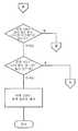
단계(1015)에서, 세그먼트 완성 모듈(907)은 세그먼트 내 추가 미처리 이미지들이 있는지를 판정한다. 만약 있으면, 세그먼트 완성 모듈(907)은 현재 미처리 이미지를 수신함으로써 단계(1007)를 반복한다. 그 다음, 단계(1009)에서, 세그먼트 완성 모듈(907)은 현재 미처리 이미지에 대한 검색 영역을 결정한다. 세그먼트의 제2 및 각각의 후속 미처리 이미지로, 이전 미처리 이미지의 위치를 지정하는 것으로부터 결정된 펜(201)의 실제 속도에 기초하여 검색 영역이 결정될 것이다. 예를 들어, 검색 영역의 중심은 이전 미처리 이미지에 대응하는 포인트에 위치될 수 있다. 그 다음, 세그먼트 완성 모듈(907)은 이전 미처리 이미지에 대한 포인트의 위치로부터 계산된 실제 펜 속도에 기초하여 검색 영역의 반지름을 결정할 수 있다. 더 구체적으로, 이전 미처리 이미지의 위치로부터 계산된 실제 펜 속도에 캡처된 이미지들 간의 시간 간격을 곱함으로써 검색 영역의 반지름이 결정될 수 있다.In step 1015, the
통상의 숙련의 당업자라면, 펜(210)을 가지고 쓰는 사용자는 최대 가속도 값에 의해 펜(201)의 속도를 변경할 수만 있다는 것을 이해할 것이다. 이 최대 가속도 값은, 예를 들어, 실험에 의해 계산될 수 있거나, 이전에 위치 지정된 이미지들 간의 실제 가속도에 기초할 수 있다. 따라서, 본 발명의 일부 실시예들에서, 제2 및 후속 미처리 이미지들에 대한 검색 영역의 반지름은 최대 가속도 값에 의해 수정될 수 있다. 예를 들어, 시간 t1, t2, 및 t3에서 캡처되고 포인트 p1, p2, 및 p3에 중심을 갖는, 스트로크 내 3개의 이미지들 f1, f2, 및 f3이 있을 수 있다. 포인트들 p1 및 p2의 위치가 결정될 수 있으면, 이 이미지들의 캡처 간에 펜의 속도 V는 V = (p2 - p1)/(t2 - t1)이다. 가속도가 -A와 A 사이의 값을 가지면, 포인트 p3에 대한 검색 영역은 위치 P=p2+V*(t3-t2) 주위를 중심으로 하고, 검색 영역의 면적은 [P-A*(t3-t2)*(t3-t2)/2,P+A*(t3-t2)*(t3-t2)/2]이 된다.Those skilled in the art will understand that a user writing with the
일단 세그먼트 완성 모듈(907)이 현재 미처리 이미지에 대한 검색 영역을 결정하면, 세그먼트 완성 모듈(907)은 단계(1011)에서 이전의 처리 이미지로부터의 원근 변환으로 미처리 이미지를 와핑하고, 와핑된 미처리 이미지와 문서의 검색 영역 간의 픽셀 단위 비교를 수행한다. 다시, 최고의 상관값을 생성하는 문서의 부분이 현재의 미처리 이미지에 대한 위치로서 선택된다. 그 후 세그먼트 완성 모듈(907)은 현재의 미처리 이미지에 대한 포인트와 이전의 미처리 이미지에 대한 포인트 사이의 거리에 기초하여 펜(201)에 대한 새로운 속도를 계산한다. 또한, 현재의 미처리 이미지의 식별된 위치에 기초하여 변환 파라미터를 갱신하여, 이미지를 처리한다. 그 후 세그먼트 완성 모듈(907)은 단계(1015)를 반복하여, 현재 세그먼트에, 남아 있는 위치 미지정 이미지들이 있는지의 여부를 결정한다.Once the
세그먼트 완성 모듈(907)은 현재 세그먼트에 위치 미지정 이미지들이 더 이상 없을 때까지 단계들(1007 및 1015)을 반복한다. 다음으로, 단계(1017)에서, 세그먼트 완성 모듈(907)은 이미지들의 시퀀스 내에 더 이상의 세그먼트들이 있는지의 여부를 결정한다. 만일 세그먼트들이 더 있다면, 세그먼트 완성 모듈(907)은 이미지들의 시퀀스 내의 모든 세그먼트들이 완성될 때까지 단계들(1003 내지 1015)을 반복한다.
모든 세그먼트들이 완성된 후에, 스트로크 내의 각각의 이미지는 문서 내에 위치 지정될 것이다. 예를 들어, 부정확한 초기 변환 파라미터 및 모션 블러(motion blur)와 같은 몇몇 요인들이 하나 이상의 위치 지정 이미지들에 대한 잘못된 위치 결과들을 초래할 수 있다. 따라서, 본 발명의 각종 실시예들은 단계(1019)에서 결과 프루닝 모듈(909)을 이용하여 결과들로부터 잘못된 위치들을 제거(prune)할 수 있다.After all segments have been completed, each image in the stroke will be positioned within the document. For example, some factors, such as incorrect initial conversion parameters and motion blur, can result in incorrect positioning results for one or more positioning images. Thus, various embodiments of the present invention may prune wrong locations from results using result pruning module 909 at step 1019.
결과 프루닝 모듈(909)은, 예를 들면, 이미지들의 시퀀스에 대한 각각의 시작 포인트들의 위치를 유지할 수 있다. 다음으로, 결과 프루닝 모듈(909)은 전체 스트로크 경로에 대한 각 포인트를 나아가면서, 최초 포인트부터 최종 포인트까지 순서대로 각 포인트를 분석한다. 더 구체적으로, 이전 포인트로부터 현재 포인트까지 및 현재 포인트로부터 다음 포인트까지의 속도가 계산된다. 또한 이 2개의 속도 값들로부터 가속도가 계산된다. 만일 속도 값 또는 가속도가 최대치를 초과하면, 현재 포인트의 위치는 잘못된 것으로 간주되어 결과들로부터 제거된다.The result pruning module 909 may maintain the location of each start point relative to the sequence of images, for example. The result pruning module 909 then analyzes each point in order from the first point to the last point, advancing each point for the entire stroke path. More specifically, the velocity from the previous point to the current point and from the current point to the next point is calculated. Acceleration is also calculated from these two velocity values. If the velocity value or acceleration exceeds the maximum, the position of the current point is considered wrong and is removed from the results.
본 발명의 각종 실시예들에서, 결과 프루닝 모듈(909)은 각 포인트의 분석을 반복할 수 있지만, 대신에 최종 포인트로부터 최초 포인트까지 역순으로 각 포인트를 분석할 수 있다. 따라서, 다음 포인트로부터 현재 포인트까지 및 현재 포인트로부터 이전 포인트까지의 속도가 계산된다. 또한 이 2개의 속도 값들로부터 가속도가 계산된다. 만일 속도 값 또는 가속도가 최대치를 초과하면, 현재 포인트의 위치는 잘못된 것으로 간주되어 결과들로부터 제거된다. 모든 잘못된 포인트들이 제거된 후에, 제거된 포인트들의 위치는 보간법(interpolation)을 이용하여 결정될 수 있다.In various embodiments of the present invention, the result pruning module 909 may repeat the analysis of each point, but instead analyze each point in reverse order from the last point to the first point. Thus, the velocity from the next point to the current point and from the current point to the previous point is calculated. Acceleration is also calculated from these two velocity values. If the velocity value or acceleration exceeds the maximum, the position of the current point is considered wrong and is removed from the results. After all erroneous points have been removed, the location of the removed points can be determined using interpolation.
<결론>Conclusion
이상 본 발명을 수행하는 현재 선호되는 양태들을 포함하는 특정 예들과 관련하여 본 발명을 설명하였지만, 숙련된 당업자라면 첨부된 청구항들에 제시된 것과 같은 발명의 의미 및 범위 내에서 상술한 시스템들 및 기술들의 다수의 변형 예들 및 대체 예들이 존재함을 이해할 것이다.While the invention has been described with reference to specific examples, including the presently preferred aspects of carrying out the invention, a person of ordinary skill in the art will appreciate that the systems and techniques described above are within the meaning and scope of the invention as set forth in the appended claims. It will be appreciated that there are many variations and alternatives.
본 발명은 이미지 내 캡처된 문서 일부의 위치를 결정하는 것으로, 특히, 문서의 이미지들을 캡처함으로써 문서 상 마크의 위치를 식별하는데 적용될 수 있다. 캡처된 이미지에 대응하는 문서 부분을 결정하기 위한 효율적인 기술이 개시되어 있다The present invention determines the position of a portion of a document captured in an image, and in particular, may be applied to identifying the position of a mark on a document by capturing images of the document. Efficient techniques for determining document portions corresponding to captured images are disclosed
Claims (17)
Translated fromKoreanApplications Claiming Priority (2)
| Application Number | Priority Date | Filing Date | Title |
|---|---|---|---|
| US10/752,081 | 2004-01-07 | ||
| US10/752,081US7529410B2 (en) | 2004-01-07 | 2004-01-07 | Local localization using fast image match |
Publications (2)
| Publication Number | Publication Date |
|---|---|
| KR20050072705A KR20050072705A (en) | 2005-07-12 |
| KR100942122B1true KR100942122B1 (en) | 2010-02-16 |
Family
ID=34592556
Family Applications (1)
| Application Number | Title | Priority Date | Filing Date |
|---|---|---|---|
| KR1020050001566AExpired - Fee RelatedKR100942122B1 (en) | 2004-01-07 | 2005-01-07 | Local Positioning Using Fast Image Matching |
Country Status (13)
| Country | Link |
|---|---|
| US (1) | US7529410B2 (en) |
| EP (1) | EP1553522A3 (en) |
| JP (1) | JP4652823B2 (en) |
| KR (1) | KR100942122B1 (en) |
| CN (1) | CN100576234C (en) |
| AU (1) | AU2004242566B2 (en) |
| BR (1) | BRPI0500014A (en) |
| CA (1) | CA2491770A1 (en) |
| MX (1) | MXPA05000419A (en) |
| MY (1) | MY144958A (en) |
| RU (1) | RU2369901C2 (en) |
| TW (1) | TWI355614B (en) |
| ZA (1) | ZA200500094B (en) |
Families Citing this family (35)
| Publication number | Priority date | Publication date | Assignee | Title |
|---|---|---|---|---|
| US7116840B2 (en) | 2002-10-31 | 2006-10-03 | Microsoft Corporation | Decoding and error correction in 2-D arrays |
| US7133563B2 (en) | 2002-10-31 | 2006-11-07 | Microsoft Corporation | Passive embedded interaction code |
| US7797369B2 (en)* | 2003-12-16 | 2010-09-14 | Seiko Epson Corporation | System and method for controlling a transmission of image data to a display device |
| US7583842B2 (en) | 2004-01-06 | 2009-09-01 | Microsoft Corporation | Enhanced approach of m-array decoding and error correction |
| US7263224B2 (en) | 2004-01-16 | 2007-08-28 | Microsoft Corporation | Strokes localization by m-array decoding and fast image matching |
| GB0417075D0 (en)* | 2004-07-30 | 2004-09-01 | Hewlett Packard Development Co | Calibrating digital pens |
| US7607076B2 (en) | 2005-02-18 | 2009-10-20 | Microsoft Corporation | Embedded interaction code document |
| US7826074B1 (en) | 2005-02-25 | 2010-11-02 | Microsoft Corporation | Fast embedded interaction code printing with custom postscript commands |
| US7599560B2 (en) | 2005-04-22 | 2009-10-06 | Microsoft Corporation | Embedded interaction code recognition |
| US7421439B2 (en) | 2005-04-22 | 2008-09-02 | Microsoft Corporation | Global metadata embedding and decoding |
| US7400777B2 (en) | 2005-05-25 | 2008-07-15 | Microsoft Corporation | Preprocessing for information pattern analysis |
| US7729539B2 (en) | 2005-05-31 | 2010-06-01 | Microsoft Corporation | Fast error-correcting of embedded interaction codes |
| US7580576B2 (en) | 2005-06-02 | 2009-08-25 | Microsoft Corporation | Stroke localization and binding to electronic document |
| US7619607B2 (en) | 2005-06-30 | 2009-11-17 | Microsoft Corporation | Embedding a pattern design onto a liquid crystal display |
| US7817816B2 (en) | 2005-08-17 | 2010-10-19 | Microsoft Corporation | Embedded interaction code enabled surface type identification |
| US7622182B2 (en) | 2005-08-17 | 2009-11-24 | Microsoft Corporation | Embedded interaction code enabled display |
| US20070216711A1 (en)* | 2006-03-14 | 2007-09-20 | Microsoft Corporation Microsoft Patent Group | Abstracting transform representations in a graphics API |
| US8096584B2 (en)* | 2006-07-24 | 2012-01-17 | 3M Innovative Properties Company | Document authentication using template matching with fast masked normalized cross-correlation |
| JP4989308B2 (en)* | 2007-05-16 | 2012-08-01 | キヤノン株式会社 | Image processing apparatus and image search method |
| TWI403940B (en)* | 2008-12-03 | 2013-08-01 | Au Optronics Corp | Detecting method for photo sensor touch panel and touch control electronic apparatus using the same |
| US8483518B2 (en) | 2010-02-19 | 2013-07-09 | Microsoft Corporation | Image-based CAPTCHA exploiting context in object recognition |
| JP2012103776A (en)* | 2010-11-08 | 2012-05-31 | Fuji Xerox Co Ltd | Track information processing device, track information processing system, and program |
| US20120272302A1 (en)* | 2011-04-21 | 2012-10-25 | Microsoft Corporation | Human User Verification |
| CN204044759U (en) | 2011-12-16 | 2014-12-24 | 3M创新有限公司 | There is the optical digitizers system of the unique photoluminescence mark in position |
| CN103377471B (en)* | 2012-04-16 | 2016-08-03 | 株式会社理光 | Object positioning method and device, optimum video camera are to determining method and apparatus |
| RU2582853C2 (en)* | 2012-06-29 | 2016-04-27 | Общество с ограниченной ответственностью "Системы Компьютерного зрения" | Device for determining distance and speed of objects based on stereo approach |
| JP6064211B2 (en)* | 2012-09-04 | 2017-01-25 | パナソニックIpマネジメント株式会社 | Handwriting input system |
| US8692212B1 (en) | 2012-10-29 | 2014-04-08 | 3M Innovative Properties Company | Optical digitizer system with position-unique photoluminescent indicia |
| US9958954B2 (en) | 2012-12-13 | 2018-05-01 | 3M Innovative Properties Company | System and methods for calibrating a digitizer system |
| JP6125333B2 (en)* | 2013-05-31 | 2017-05-10 | 株式会社東芝 | Search device, method and program |
| KR101726820B1 (en)* | 2014-10-13 | 2017-04-13 | 주식회사 엘지화학 | Ethylene/1-hexene or ethylene/1-butene copolymer having excellent processibility and environmental stress crack resistance |
| CN106056605B (en)* | 2016-05-26 | 2018-09-18 | 西安空间无线电技术研究所 | A kind of in-orbit high precision image localization method based on images match |
| CN108525304B (en)* | 2018-04-16 | 2021-06-22 | 网易(杭州)网络有限公司 | Image analysis method and device, storage medium and electronic device |
| CN110119216A (en)* | 2019-06-12 | 2019-08-13 | 卓阅科技(深圳)有限公司 | Smart pen and teaching equipment |
| CN113434715B (en)* | 2020-03-23 | 2024-06-21 | 瑞昱半导体股份有限公司 | Method for searching an image and image processing circuit |
Citations (4)
| Publication number | Priority date | Publication date | Assignee | Title |
|---|---|---|---|---|
| US5577135A (en) | 1994-03-01 | 1996-11-19 | Apple Computer, Inc. | Handwriting signal processing front-end for handwriting recognizers |
| US5698822A (en) | 1994-05-16 | 1997-12-16 | Sharp Kabushiki Kaisha | Input and display apparatus for handwritten characters |
| US5740273A (en) | 1995-06-05 | 1998-04-14 | Motorola, Inc. | Method and microprocessor for preprocessing handwriting having characters composed of a preponderance of straight line segments |
| US7068821B2 (en) | 2001-01-29 | 2006-06-27 | Canon Kabushiki Kaisha | Information processing method and apparatus |
Family Cites Families (12)
| Publication number | Priority date | Publication date | Assignee | Title |
|---|---|---|---|---|
| SU1236518A1 (en)* | 1983-08-16 | 1986-06-07 | Московский Ордена Трудового Красного Знамени Электротехнический Институт Связи | Device for recognizing handwritten symbols |
| JPS6472293A (en)* | 1987-09-14 | 1989-03-17 | Sanyo Electric Co | Handwritten character and graphic recognizing method |
| US5001765A (en)* | 1989-01-05 | 1991-03-19 | International Business Machines Corporation | Fast spatial segmenter for handwritten characters |
| US5220649A (en)* | 1991-03-20 | 1993-06-15 | Forcier Mitchell D | Script/binary-encoded-character processing method and system with moving space insertion mode |
| JPH06290301A (en)* | 1993-04-01 | 1994-10-18 | Olympus Optical Co Ltd | Character/graphic recognizing device |
| JP3139902B2 (en)* | 1993-12-22 | 2001-03-05 | 株式会社東芝 | Figure recognition method and apparatus |
| US5991441A (en)* | 1995-06-07 | 1999-11-23 | Wang Laboratories, Inc. | Real time handwriting recognition system |
| US6686910B2 (en)* | 1996-04-22 | 2004-02-03 | O'donnell, Jr. Francis E. | Combined writing instrument and digital documentor apparatus and method of use |
| AU2351299A (en)* | 1998-01-28 | 1999-08-16 | California Institute Of Technology | Camera-based handwriting tracking |
| US6864880B2 (en)* | 2000-03-21 | 2005-03-08 | Anoto Ab | Device and method for communication |
| SE0000940L (en)* | 2000-03-21 | 2001-09-22 | Anoto Ab | Device and method of communication |
| US20020163511A1 (en)* | 2000-11-29 | 2002-11-07 | Sekendur Oral Faith | Optical position determination on any surface |
- 2004
- 2004-01-07USUS10/752,081patent/US7529410B2/ennot_activeExpired - Fee Related
- 2004-12-29TWTW093141197Apatent/TWI355614B/ennot_activeIP Right Cessation
- 2004-12-30RURU2004139199/09Apatent/RU2369901C2/ennot_activeIP Right Cessation
- 2004-12-31AUAU2004242566Apatent/AU2004242566B2/ennot_activeCeased
- 2005
- 2005-01-03MYMYPI20050006Apatent/MY144958A/enunknown
- 2005-01-05EPEP05000153Apatent/EP1553522A3/ennot_activeWithdrawn
- 2005-01-05ZAZA200500094Apatent/ZA200500094B/enunknown
- 2005-01-06BRBR0500014-9Apatent/BRPI0500014A/ennot_activeIP Right Cessation
- 2005-01-06CACA002491770Apatent/CA2491770A1/ennot_activeAbandoned
- 2005-01-07MXMXPA05000419Apatent/MXPA05000419A/enactiveIP Right Grant
- 2005-01-07CNCN200510004068Apatent/CN100576234C/ennot_activeExpired - Fee Related
- 2005-01-07JPJP2005002847Apatent/JP4652823B2/ennot_activeExpired - Fee Related
- 2005-01-07KRKR1020050001566Apatent/KR100942122B1/ennot_activeExpired - Fee Related
Patent Citations (4)
| Publication number | Priority date | Publication date | Assignee | Title |
|---|---|---|---|---|
| US5577135A (en) | 1994-03-01 | 1996-11-19 | Apple Computer, Inc. | Handwriting signal processing front-end for handwriting recognizers |
| US5698822A (en) | 1994-05-16 | 1997-12-16 | Sharp Kabushiki Kaisha | Input and display apparatus for handwritten characters |
| US5740273A (en) | 1995-06-05 | 1998-04-14 | Motorola, Inc. | Method and microprocessor for preprocessing handwriting having characters composed of a preponderance of straight line segments |
| US7068821B2 (en) | 2001-01-29 | 2006-06-27 | Canon Kabushiki Kaisha | Information processing method and apparatus |
Also Published As
| Publication number | Publication date |
|---|---|
| TW200532585A (en) | 2005-10-01 |
| AU2004242566A1 (en) | 2005-07-21 |
| JP4652823B2 (en) | 2011-03-16 |
| EP1553522A3 (en) | 2011-09-28 |
| TWI355614B (en) | 2012-01-01 |
| US7529410B2 (en) | 2009-05-05 |
| MY144958A (en) | 2011-11-30 |
| CA2491770A1 (en) | 2005-07-07 |
| CN100576234C (en) | 2009-12-30 |
| BRPI0500014A (en) | 2005-08-09 |
| KR20050072705A (en) | 2005-07-12 |
| RU2004139199A (en) | 2006-06-10 |
| US20050147281A1 (en) | 2005-07-07 |
| AU2004242566B2 (en) | 2010-03-04 |
| ZA200500094B (en) | 2006-09-27 |
| MXPA05000419A (en) | 2006-02-08 |
| RU2369901C2 (en) | 2009-10-10 |
| JP2005327246A (en) | 2005-11-24 |
| EP1553522A2 (en) | 2005-07-13 |
| CN1655178A (en) | 2005-08-17 |
Similar Documents
| Publication | Publication Date | Title |
|---|---|---|
| KR100942122B1 (en) | Local Positioning Using Fast Image Matching | |
| KR101026580B1 (en) | A system for encoding an image of a document and a method for encoding a data stream as a pattern | |
| KR101037238B1 (en) | Stroke localization by m-array decoding and fast image matching | |
| RU2360303C2 (en) | Positionally encoded document image analysis and labelling | |
| KR100984402B1 (en) | Decoding and Error Correction in 2-D Arrays | |
| US7885465B2 (en) | Document portion identification by fast image mapping | |
| CN100377049C (en) | Global positioned statistical model | |
| KR101037232B1 (en) | Camera and nib mapping and calibration | |
| KR101064845B1 (en) | Document image encoding systems, codebook generation systems and methods, codebook navigation systems, and information encoding methods | |
| HK1079318A (en) | Determining positions of images of a stroke |
Legal Events
| Date | Code | Title | Description |
|---|---|---|---|
| PA0109 | Patent application | St.27 status event code:A-0-1-A10-A12-nap-PA0109 | |
| PG1501 | Laying open of application | St.27 status event code:A-1-1-Q10-Q12-nap-PG1501 | |
| A201 | Request for examination | ||
| A302 | Request for accelerated examination | ||
| P11-X000 | Amendment of application requested | St.27 status event code:A-2-2-P10-P11-nap-X000 | |
| P13-X000 | Application amended | St.27 status event code:A-2-2-P10-P13-nap-X000 | |
| PA0201 | Request for examination | St.27 status event code:A-1-2-D10-D11-exm-PA0201 | |
| PA0302 | Request for accelerated examination | St.27 status event code:A-1-2-D10-D17-exm-PA0302 St.27 status event code:A-1-2-D10-D16-exm-PA0302 | |
| E701 | Decision to grant or registration of patent right | ||
| PE0701 | Decision of registration | St.27 status event code:A-1-2-D10-D22-exm-PE0701 | |
| GRNT | Written decision to grant | ||
| PR0701 | Registration of establishment | St.27 status event code:A-2-4-F10-F11-exm-PR0701 | |
| PR1002 | Payment of registration fee | St.27 status event code:A-2-2-U10-U11-oth-PR1002 Fee payment year number:1 | |
| PG1601 | Publication of registration | St.27 status event code:A-4-4-Q10-Q13-nap-PG1601 | |
| R17-X000 | Change to representative recorded | St.27 status event code:A-5-5-R10-R17-oth-X000 | |
| FPAY | Annual fee payment | Payment date:20130121 Year of fee payment:4 | |
| PR1001 | Payment of annual fee | St.27 status event code:A-4-4-U10-U11-oth-PR1001 Fee payment year number:4 | |
| LAPS | Lapse due to unpaid annual fee | ||
| PC1903 | Unpaid annual fee | St.27 status event code:A-4-4-U10-U13-oth-PC1903 Not in force date:20140205 Payment event data comment text:Termination Category : DEFAULT_OF_REGISTRATION_FEE | |
| PN2301 | Change of applicant | St.27 status event code:A-5-5-R10-R13-asn-PN2301 St.27 status event code:A-5-5-R10-R11-asn-PN2301 | |
| PC1903 | Unpaid annual fee | St.27 status event code:N-4-6-H10-H13-oth-PC1903 Ip right cessation event data comment text:Termination Category : DEFAULT_OF_REGISTRATION_FEE Not in force date:20140205 | |
| PN2301 | Change of applicant | St.27 status event code:A-5-5-R10-R11-asn-PN2301 | |
| R18-X000 | Changes to party contact information recorded | St.27 status event code:A-5-5-R10-R18-oth-X000 |