KR100938802B1 - Heat exchanger having micro-channels - Google Patents
Heat exchanger having micro-channelsDownload PDFInfo
- Publication number
- KR100938802B1 KR100938802B1KR1020090051898AKR20090051898AKR100938802B1KR 100938802 B1KR100938802 B1KR 100938802B1KR 1020090051898 AKR1020090051898 AKR 1020090051898AKR 20090051898 AKR20090051898 AKR 20090051898AKR 100938802 B1KR100938802 B1KR 100938802B1
- Authority
- KR
- South Korea
- Prior art keywords
- heat exchanger
- low temperature
- curved
- flow path
- micro
- Prior art date
- Legal status (The legal status is an assumption and is not a legal conclusion. Google has not performed a legal analysis and makes no representation as to the accuracy of the status listed.)
- Expired - Fee Related
Links
Images


Classifications
- F—MECHANICAL ENGINEERING; LIGHTING; HEATING; WEAPONS; BLASTING
- F28—HEAT EXCHANGE IN GENERAL
- F28D—HEAT-EXCHANGE APPARATUS, NOT PROVIDED FOR IN ANOTHER SUBCLASS, IN WHICH THE HEAT-EXCHANGE MEDIA DO NOT COME INTO DIRECT CONTACT
- F28D9/00—Heat-exchange apparatus having stationary plate-like or laminated conduit assemblies for both heat-exchange media, the media being in contact with different sides of a conduit wall
- F28D9/0062—Heat-exchange apparatus having stationary plate-like or laminated conduit assemblies for both heat-exchange media, the media being in contact with different sides of a conduit wall the conduits for one heat-exchange medium being formed by spaced plates with inserted elements
- F—MECHANICAL ENGINEERING; LIGHTING; HEATING; WEAPONS; BLASTING
- F28—HEAT EXCHANGE IN GENERAL
- F28F—DETAILS OF HEAT-EXCHANGE AND HEAT-TRANSFER APPARATUS, OF GENERAL APPLICATION
- F28F3/00—Plate-like or laminated elements; Assemblies of plate-like or laminated elements
- F28F3/02—Elements or assemblies thereof with means for increasing heat-transfer area, e.g. with fins, with recesses, with corrugations
- F—MECHANICAL ENGINEERING; LIGHTING; HEATING; WEAPONS; BLASTING
- F28—HEAT EXCHANGE IN GENERAL
- F28D—HEAT-EXCHANGE APPARATUS, NOT PROVIDED FOR IN ANOTHER SUBCLASS, IN WHICH THE HEAT-EXCHANGE MEDIA DO NOT COME INTO DIRECT CONTACT
- F28D1/00—Heat-exchange apparatus having stationary conduit assemblies for one heat-exchange medium only, the media being in contact with different sides of the conduit wall, in which the other heat-exchange medium is a large body of fluid, e.g. domestic or motor car radiators
- F28D1/02—Heat-exchange apparatus having stationary conduit assemblies for one heat-exchange medium only, the media being in contact with different sides of the conduit wall, in which the other heat-exchange medium is a large body of fluid, e.g. domestic or motor car radiators with heat-exchange conduits immersed in the body of fluid
- F28D1/03—Heat-exchange apparatus having stationary conduit assemblies for one heat-exchange medium only, the media being in contact with different sides of the conduit wall, in which the other heat-exchange medium is a large body of fluid, e.g. domestic or motor car radiators with heat-exchange conduits immersed in the body of fluid with plate-like or laminated conduits
- F—MECHANICAL ENGINEERING; LIGHTING; HEATING; WEAPONS; BLASTING
- F28—HEAT EXCHANGE IN GENERAL
- F28F—DETAILS OF HEAT-EXCHANGE AND HEAT-TRANSFER APPARATUS, OF GENERAL APPLICATION
- F28F13/00—Arrangements for modifying heat-transfer, e.g. increasing, decreasing
- F28F13/06—Arrangements for modifying heat-transfer, e.g. increasing, decreasing by affecting the pattern of flow of the heat-exchange media
- F—MECHANICAL ENGINEERING; LIGHTING; HEATING; WEAPONS; BLASTING
- F28—HEAT EXCHANGE IN GENERAL
- F28F—DETAILS OF HEAT-EXCHANGE AND HEAT-TRANSFER APPARATUS, OF GENERAL APPLICATION
- F28F3/00—Plate-like or laminated elements; Assemblies of plate-like or laminated elements
- F28F3/02—Elements or assemblies thereof with means for increasing heat-transfer area, e.g. with fins, with recesses, with corrugations
- F28F3/04—Elements or assemblies thereof with means for increasing heat-transfer area, e.g. with fins, with recesses, with corrugations the means being integral with the element
- F28F3/048—Elements or assemblies thereof with means for increasing heat-transfer area, e.g. with fins, with recesses, with corrugations the means being integral with the element in the form of ribs integral with the element or local variations in thickness of the element, e.g. grooves, microchannels
- F—MECHANICAL ENGINEERING; LIGHTING; HEATING; WEAPONS; BLASTING
- F28—HEAT EXCHANGE IN GENERAL
- F28F—DETAILS OF HEAT-EXCHANGE AND HEAT-TRANSFER APPARATUS, OF GENERAL APPLICATION
- F28F2260/00—Heat exchangers or heat exchange elements having special size, e.g. microstructures
- F28F2260/02—Heat exchangers or heat exchange elements having special size, e.g. microstructures having microchannels
Landscapes
- Engineering & Computer Science (AREA)
- Physics & Mathematics (AREA)
- Thermal Sciences (AREA)
- Mechanical Engineering (AREA)
- General Engineering & Computer Science (AREA)
- Heat-Exchange Devices With Radiators And Conduit Assemblies (AREA)
- Physical Or Chemical Processes And Apparatus (AREA)
Abstract
Description
Translated fromKorean본 발명은 미세가공 기술에 의하여 마이크로 채널을 형성시킨 열교환기에 관한 것이다.The present invention relates to a heat exchanger in which microchannels are formed by micromachining techniques.
특수한 용도에 사용되는 열교환기는 다른 일반적인 열교환기와는 달리 고온 고압이라는 환경에 사용되거나, 중량 또는 공간 등과 같은 제한 조건을 만족시키기 위해 소형화와 내구성이 요구되는 경우도 있다.Heat exchangers used for special applications may be used in environments of high temperature and high pressure, unlike other general heat exchangers, or may require miniaturization and durability in order to satisfy constraints such as weight or space.
기체 대 기체(Gas-to-Gas)만의 열교환은 총열전달계수가 낮아 동일한 열교환을 위해서 더 큰 전열면적을 필요로 하게 되며, 이는 중량 및 공간 제한조건이 있는 상황에는 채택이 어려운 점이 있다.Gas-to-Gas only heat exchange has a low total heat transfer coefficient, requiring a larger heat transfer area for the same heat exchange, which is difficult to adopt in situations with weight and space constraints.
마이크로 채널 열교환기의 일종인 Printed Circuit Heat Exchanger(PCHE)는 식각가공하여 유로를 형성한 서로 다른 판을 격판을 사이에 두고 교대로 접합하여 만든 열교환기로서, 밀리미터급의 작은 유로를 형성시킬 수 있으며, 기체뿐만 아니라 액체도 자유롭게 흐르면서도 큰 전열면적을 갖게 함으로써 사용공간대비 큰 전열면적을 갖는 장점이 있다. 또한, PCHE는 고온 고압 사용 환경에 유리한 열교환기를 구성할 수 있는 장점이 있으며, 미세 전자기기 시스템(Micro electro mechanical system;MEMS) 분야의 발전으로 다양한 미세 가공기술들을 활용하여 다양한 형상으로 제작할 수 있다.Printed Circuit Heat Exchanger (PCHE), a type of micro-channel heat exchanger, is a heat exchanger made by alternately joining different plates that are formed by etching to form flow paths, and can form small millimeter flow paths. In addition, it has the advantage of having a large heat transfer area compared to the use space by having a large heat transfer area while freely flowing not only gas but also liquid. In addition, PCHE has the advantage of constituting a heat exchanger that is advantageous for high temperature and high pressure use environment, and can be manufactured in various shapes by utilizing various fine processing techniques due to the development of the micro electro mechanical system (MEMS).
소형성과 우수한 성능을 갖는 PCHE는 컴퓨터, 반도체를 비롯한 정보기술 분야에서 뿐만 아니라 에너지 관련 산업 등의 에너지기술(Energy Technology)분야에서도 다양하게 적용되고 있다. 나아가, 고온, 고압, 마이크로채널 열교환기를 필요로 하는 석유화학 플랜트로부터 연료전지 반응기 및 폐열회수장치, CO2 히트펌프 및 온수기의 냉동공조산업, 등 타 산업들에 파급효과가 매우 크다.PCHE, which has small size and excellent performance, is widely applied not only in information technology fields including computers and semiconductors but also in energy technology fields such as energy related industries. In addition, the petrochemical plant requiring high temperature, high pressure, microchannel heat exchanger has a great effect on other industries such as fuel cell reactor and waste heat recovery device, CO2 heat pump and water heater refrigeration and air conditioning industry.
일반적인 경우 열교환기는 열전달이 증가함과 동시에 압력강하가 증가하지만, 마이크로채널 열교환기의 형상 설계를 통해 압력 강하량은 작게 유지하면서 열전달량은 크게 발생시킬 수 있다.In general, the heat exchanger increases pressure while increasing heat transfer, but through the shape design of the microchannel heat exchanger, it is possible to generate a large amount of heat transfer while keeping the pressure drop small.
그런데, 알려져 있는 종래의 방식에 의한 사각형상의 열교환기의 경우, 유로의 형상과 외형이 단순하기 때문에 유로의 형상을 설계하는 것이 비교적 용이하나, 열교환기가 장착될 장치 내의 공간 조건을 맞추기 어려운 경우가 많다. 특히, 전체 외형이 곡선을 이루는 경우라면 동일한 길이를 갖는 유로의 설계가 더욱 어려운 문제가 있다.By the way, in the case of the rectangular heat exchanger by the conventional method known in the art, it is relatively easy to design the shape of the flow path because the shape and the shape of the flow path are simple, but it is often difficult to match the space conditions in the apparatus to which the heat exchanger is mounted. . In particular, if the entire shape is curved, the design of the flow path having the same length is more difficult.
본 발명은 상기와 같은 점을 감안하여 안출된 것으로, 외형이 곡선을 이루는 경우에 동일한 길이를 갖는 마이크로 채널들을 형성시킴으로써 고성능을 구현할 수 있는 열교환기를 제공하는데 그 목적이 있다.The present invention has been made in view of the above, and an object thereof is to provide a heat exchanger capable of realizing high performance by forming microchannels having the same length when the outer shape is curved.
상기와 같은 과제를 해결하기 위해 본 발명과 관련된 마이크로채널 열교환기는, 마이크로 채널을 형성한 복수의 레이어가 적층 형성된 열교환기 몸체부; 상기 열교환기 몸체부의 일측 단부에 상호 분리되게 부착되는 고온부 입구몸체 및 저온부 출구몸체; 및 상기 열교환기 몸체부의 타측 단부에 상호 분리되게 부착되는 저온부 입구몸체 및 고온부 출구몸체를 포함하고, 상기 열교환기 몸체부의 폭을 형성하는 양 측면은 제1곡면 프로파일과 상기 제1곡면 프로파일에 평행한 제2곡면 프로파일을 가질 수 있게 각각 형성될 수 있다.In order to solve the above problems, the microchannel heat exchanger according to the present invention includes: a heat exchanger body part in which a plurality of layers in which microchannels are formed are stacked; A high temperature part inlet body and a low temperature part outlet body which are separately attached to one end of the heat exchanger body part; And a low temperature part inlet body and a high temperature part outlet body attached to the other end of the heat exchanger body part separately from each other, wherein both sides defining the width of the heat exchanger body part are parallel to the first curved profile and the first curved profile. Each may be formed to have a second curved profile.
본 발명과 관련된 일 예로서, 상기 열교환기 몸체부는, 고온유체가 흐르기 위한 평행한 복수의 제1마이크로 채널이 형성된 고온부 레이어; 및 저온유체가 흐르기 위한 평행한 복수의 제2마이크로 채널이 형성된 저온부 레이어를 포함하여 구성될 수 있다.As an example related to the present invention, the heat exchanger body part may include: a high temperature part layer having a plurality of parallel first micro channels through which a high temperature fluid flows; And a low temperature layer in which a plurality of parallel second micro channels for the low temperature fluid flows.
본 발명과 관련된 일 예로서, 상기 제1마이크로 채널 및 제2마이크로 채널은 2 이상인 n개의 유로를 포함하고, i번째(i는 자연수) 유로는 Xi의 길이를 갖는 입구 부와, Wi의 길이를 갖는 곡선부 및 Yi의 길이를 갖는 출구부를 포함하며, 상기 Xi, Yi 및 Wi는 다음의 식을 만족시키도록 구성될 수 있다.As an example related to the present invention, the first micro channel and the second micro channel include n flow paths having two or more, and the i-th (i is a natural number) flow path has an inlet having a length of Xi and Wi ; And a curved portion having a length and an outlet portion having a length of Yi , wherein Xi , Yi and Wi may be configured to satisfy the following equation.
Xi + Yi + Wi = 일정Xi + Yi + Wi = Schedule
본 발명과 관련된 일 예로서, 상기 곡선부들 어느 하나의 곡선부와 인접된 다른 하나의 곡선부 사이의 폭은 길이방향을 따라 일정하게 유지되도록 형성될 수 있다.As an example related to the present invention, the width between one curved portion of the curved portion and the other adjacent curved portion may be formed to remain constant along the longitudinal direction.
본 발명과 관련된 일 예로서, 상기 곡선부는 파형으로 형성될 수 있다.As an example related to the present invention, the curved portion may be formed in a waveform.
본 발명과 관련된 열교환기에 의하면, 곡면 외형이 적용된 몸체부에 마이크로채널을 형성함으로써 직선유로를 갖는 종래의 열교환기에 비하여 열교환 효율을 대폭 향상시킬 수 있다.According to the heat exchanger according to the present invention, the heat exchange efficiency can be significantly improved as compared with the conventional heat exchanger having a linear flow path by forming a microchannel in the body portion to which the curved outer surface is applied.
본 발명과 관련된 일 예에 의하면, 곡면 외형의 몸체부에 파형의 마이크로 채널을 적용하되, 각 마이크로 채널의 총길이와 단면적을 갖도록 함으로써 유로별 편차를 최소화시킬 수 있다.According to an example related to the present invention, the microchannel of the waveform is applied to the body portion of the curved shape, and the microchannels have a total length and a cross-sectional area, thereby minimizing the deviation of each channel.
또한 이와 같이 구성된 곡면 외형을 가지면서도 열전달 성능이 우수한 열교환기는 직선형의 종래의 열교환기를 설치하기 어려운 곳에서도 용이하게 설치될 수 있어 장착성을 개선시킨다.In addition, the heat exchanger having a curved shape configured as described above and excellent in heat transfer performance can be easily installed even in a place where it is difficult to install a conventional linear heat exchanger.
이하, 본 발명과 관련된 마이크로채널 열교환기를 첨부한 도면을 참고로 하 여 상세히 설명한다.Hereinafter, with reference to the accompanying drawings, a microchannel heat exchanger related to the present invention will be described in detail.
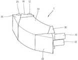
도 1은 본 발명과 관련된 마이크로 채널 열교환기의 일 예를 보인 사시도이다. 도 1에 도시된 것과 같이, 열교환기는 곡선 형상을 갖는 열교환기 몸체부(10)와, 열교환기 몸체부(10)의 일측 단부에 상호 분리되게(seperated) 부착된 고온부 입구몸체(20) 및 저온부 출구몸체(50)와, 열교환기 몸체부(10)의 타측 단부에 부착된 저온부 입구몸체(40) 및 고온부 출구몸체(30)를 포함하고 있다.1 is a perspective view showing an example of a micro-channel heat exchanger according to the present invention. As shown in FIG. 1, the heat exchanger includes a heat
열교환기 몸체부(10)의 폭을 이루기 위한 양 측면(60A)(60B) 중 어느 한 측면(60A)은 제1곡면 프로파일을 가지며, 다른 한 측면(60B)은 제1곡면 프로파일과 평행한 제2곡면 프로파일을 갖는다. 제1곡면 프로파일과 제2곡면 프로파일은 원호(arc) 형태로 형성되는 것이 가능하며, 나아가 타원 또는 포물선이나 이들이 복합된 형태로 형성될 수도 있다.Either
고온부 입구몸체(20)의 단부에는 고온입구파이프(21)가 형성되어 있으며, 하나의 고온입구파이프(21)에서 들어온 고온유체는 고온부 입구몸체(20)에 의하여 각 마이크로 채널로 분산되어 열교환기 몸체부(10) 내부를 흐르며 저온유체와 열교환을 하고 고온부 출구몸체(30)에서 합쳐진 후 고온출구파이프(31)를 통하여 배출된다. 마찬가지 방법으로, 저온부 입구몸체(40)의 단부에는 저온입구파이프(41)가 형성되어 있으며, 하나의 저온입구파이프(41)에서 들어온 저온유체는 저온부 입구몸체(40)에 의하여 상기 고온부 마이크로 채널과는 상이한 마이크로 채널로 분산되어 열교환기 몸체부(10) 내부를 흐르며 고온유체와 열교환을 하고 저온부 출구몸체(50)에서 합쳐진 후 저온출구파이프(51)를 통하여 배출된다.The high
도 2는 도 1의 마이크로채널 열교환기의 저온부 입구몸체와 고온부 츨구몸체를 열교환기 몸체부로부터 분리하여 도시한 분리 사시도이고, 도 3은 열교환몸체부를 이루는 단위 모듈의 분해 사시도이다.FIG. 2 is an exploded perspective view illustrating the low temperature part inlet body and the high temperature part body of the microchannel heat exchanger of FIG. 1 separated from the heat exchanger body part, and FIG. 3 is an exploded perspective view of a unit module constituting the heat exchange body part.
도 2 및 도 3에 의하면, 열교환기 몸체부(10)는 마이크로 채널이 형성된 레이어가 복수 개로 적층되어 있는 구조로 되어 있다.2 and 3, the heat
단위 모듈(10')은 고온부 레이어(12), 저온부 레이어(13) 및 격판(11)으로 이루어져 있다. 고온부 레이어(12)에는 고온유체가 흐르는 복수의 제1마이크로 채널(12a)이 형성되어 있으며, 저온부 레이어(13)에는 저온유체가 흐르는 복수의 제2마이크로 채널(13a)이 형성되어 있다.The
단위 모듈(10')을 이루는 고온부 레이어(12)와 저온부 레이어(13)는 모두 평면도로 보았을 때에는 위에서 설명한 두 개의 측면부(60A,60B) 외에 단부면들(61A,61B,61C,61D)도 공통으로 포함한다. 이들 단부면(61A,61B,61C,61D)은 같은 사이즈를 갖는 고온부 입구몸체(20) 및 저온부 출구몸체(50)와, 고온부 출구몸체(30) 및 저온부 입구몸체(40)가 부착될 수 있도록 중심 원호에 대하여 대칭 형태로 되어 있다.In the plan view, both the
고온부 레이어(12)와 저온부 레이어(13)는 격판(11)을 사이에 두고 접합됨으로써, 제1마이크로 채널(12a)과 제2마이크로 채널(13a)을 각각 밀폐시킨다. 따라서, 제1마이크로 채널(12a)을 흐르는 고온유체는 격판(11)을 통하여 제2마이크로 채널(13a)의 저온유체와 열교환을 하게 된다.The
마이크로채널 열교환기(1)는 각 채널에 걸리는 유동 분배를 균일하게 하기 위해 압력강하량를 일정하게 맞추는 방법을 사용하고 있다. 즉, 열교환기 효율을 결정하는 중요한 인자가 될 수 있는 열교환기의 유로길이는 각 유로로 유입되는 유량의 편차로 인한 효율감소를 제거하기 위하여, 각각 모두 같게 설정될 필요가 있다. 만약 유로 길이가 달라지면, 유로길이가 짧은 쪽으로 유량이 과다 공급되면서 열교환기의 전체 효율에 치명적인 영향을 주게 된다. 또한, 압력강하량를 일정하게 맞추기 위해 각 채널에 흐르는 모든 유로의 전체 길이와 형상을 동일하도록 제작하고 있다. 한편, 직선형 유로보다 물결무늬 모양의 파형유로가 열전달과 압력강하가 큰 형상이지만, 유로의 진행방향 기준으로 약 30˚에서 압력강하 대비 열전달이 가장 효과적이라는 것이 알려져 있다.The
따라서, 본 실시예는 곡면 외형 형상을 갖는 열교환기의 고효율화를 위하여, 곡선 외형을 갖는 열교환기 몸체부(10) 내부를 흐르는 유로를 파형으로 구현하면서도 각 유로의 총 길이를 일정하게 형성시킨 것을 개시한다.Therefore, the present embodiment discloses that in order to improve the efficiency of the heat exchanger having a curved outer shape, the flow path flowing inside the heat
도 4는 마이크로 채널의 각각의 형상을 개략적인 평면도이다.4 is a schematic plan view of the shape of each of the microchannels.
즉, 각각의 유로길이를 모두 일정하게 유지하기 위한 하나의 방법으로써, 입구부, 출구부 및 내부유로부로 구분될 수 있는 열교환기 몸체부의 유로형상을 도 4에서와 같이 입구부 길이(X1, ..., Xi, ..., Xn)와 출구부 길이(Y1, ...,, Yi, ..., Yn)의 합을 일정하게 하고, 내부유로의 길이(W1, ..., Wi, ..., Wn)를 동일하게 하여 전체 유로길이를 일정하게 한 것이다.That is, as a way to maintain a constant all the respective flow path length, the inlet portion, outlet portion and a heat exchanger that can be divided parts of the inner flow path body portion, such as a flow path shape as in Figure 4 the inlet section length (X1, ..., Xi , ..., Xn ) and the sum of the exit lengths (Y1 , ... ,, Yi , ..., Yn ) are constant, and the length of the inner flow path (W1 , ..., Wi , ..., Wn ) are the same to make the entire flow path length constant.
이때 유로의 단면적이 각 유로별로 차이가 있을 경우 동일한 길이에도 불구하고 열교환 효율이 나빠질 수 있기 때문에, 유로의 단면적도 동일하게 유지되도록 하는 것이 바람직하다.In this case, if the cross-sectional area of the flow path is different for each flow path, the heat exchange efficiency may deteriorate despite the same length.
열교환기의 효율 증가를 위하여 열교환 판의 유로 형상을 단순 평행옵셋 방법으로 파형 형상의 유로로 설계하는 경우, 유로의 겹침 현상이 발생할 수 있다.In order to increase the efficiency of the heat exchanger, when the flow path of the heat exchanger plate is designed as a corrugated flow path by a simple parallel offset method, overlapping of the flow paths may occur.
도 5는 본 발명과 관련된 일 예로서, 완만한 곡선형 유로(15a)가 적용된 마이크로 채널(15)의 평면도이다. 도 5에 도시된 마이크로 채널(15)의 경우, 유로(15a)간의 겹칩은 발생하지 않으며, 유로의 총합은 일정하다.FIG. 5 is a plan view of the
도 6은 본 발명과 관련된 일 예로서, 파형 유로를 작도하기 위한 과정을 보인 설명도이다.6 is an explanatory diagram showing a process for constructing a waveform flow path as an example related to the present invention.
도 6(a)에 도시된 것과 같이, 우선, 구현하려는 곡면 형상을 결정하고 이를 제1가상선(71)으로 작도한다.As shown in FIG. 6 (a), first, a curved shape to be implemented is determined and drawn as a first
다음으로 도 6(b)와 같이, 제1가상선(71)과 동일한 형상으로 형성된 제2가상선(74)을 중심선(72)에 맞추어 원하는 간격(M)으로 띄어 준다.Next, as shown in FIG. 6B, the second
그리고, 중심선(72)을 기준으로 하여 제1가상선(71) 및 제2가상선(74)을 일정한 W의 간격으로 세로 가상선들(75)을 작도한다.The vertical
다음으로, 도 6(c)에 도시된 것과 같이, W의 간격으로 그려준 세로 가상선들(75)과 M간격으로 띄어준 제1가상선(71) 및 제2가상선(74)의 교차점들을 잇는다.Next, as shown in FIG. 6C, intersection points of the vertical
그리고, 도 6(d)와 같이 교차점의 모서리를 곡선으로 처리하면 파형의 제1중심선(77)이 완료된다. 이렇게 파형유로의 제1중심선(77)을 파형의 폭만큼 띄어 작도하면 유로 1개가 완성된다.As shown in FIG. 6 (d), when the edges of the intersection points are curved, the
이와 같이 작도된 마이크로 채널은 도 7에 도시되어 있다. 즉, 도 7은 본 발명과 관련된 마이크로 채널의 일 평면도로서, 유로간의 겹침이 없으면서도 파형의 곡선유로를 갖는 마이크로 채널(16a)을 얻을 수 있다. 파형의 마이크로 채널(16a)은 직선유로만을 갖는 종래의 예에 비하여 열교환기의 성능이 월등히 향상될 뿐만 아니라, 도 5에서 도시한 완만한 곡선부를 갖는 마이크로 채널에 비하여도 열교환기의 성능이 향상될 수 있다.The microchannel thus constructed is shown in FIG. 7. That is, Fig. 7 is a plan view of the microchannels related to the present invention, and it is possible to obtain a
이와 같이, 두 변이 곡면 형상을 갖는 몸체부(10)에 압력강하 대비 열전달이 우수한 파형 형상을 적용함으로써 몸체부(10)의 곡면프로파일의 크기를 줄이고, 파형유로의 진행각이 위치에 따라 달라지도록 구성할 수 있다.As such, by applying a wave shape having excellent heat transfer to pressure drop to the
상기와 같이 설명된 마이크로 채널을 갖는 열교환기는 상기 설명된 실시예들의 구성과 방법이 한정되게 적용되지 않는다. 상기 실시예들은 당업자에 의하여 다양한 변형이 이루어질 수 있으며, 각 실시예들의 전부 또는 일부가 선택적으로 조합되어 구성될 수도 있다.The heat exchanger having the micro channel described above is not limited in its construction and method. The embodiments may be variously modified by those skilled in the art, and all or some of the embodiments may be selectively combined.
도 1은 본 발명과 관련된 마이크로 채널 열교환기의 일 예를 보인 사시도1 is a perspective view showing an example of a micro-channel heat exchanger related to the present invention
도 2는 도 1의 마이크로채널 열교환기의 저온부 입구몸체와 고온부 츨구몸체를 열교환기 몸체부로부터 분리하여 도시한 분리 사시도FIG. 2 is an exploded perspective view illustrating the low temperature inlet body and the high temperature heating body of the microchannel heat exchanger of FIG. 1 separated from the heat exchanger body part.
도 3은 열교환몸체부를 이루는 단위 모듈의 분해 사시도Figure 3 is an exploded perspective view of a unit module constituting the heat exchange body
도 4는 마이크로 채널의 각각의 형상을 개략적인 평면도4 is a schematic plan view of the shape of each of the microchannels;
도 5는 본 발명과 관련된 일 예로서, 완만한 곡선형 유로가 적용된 마이크로 채널의 평면도5 is a plan view of a micro channel to which a smooth curved flow path is applied as an example related to the present invention.
도 6은 본 발명과 관련된 일 예로서, 파형 유로를 작도하기 위한 과정을 보인 설명도6 is an explanatory diagram showing a process for constructing a waveform flow path as an example related to the present invention;
도 7은 본 발명과 관련된 마이크로 채널의 일 평면도7 is a plan view of a microchannel associated with the present invention.
**도면중 주요부분에 대한 부호의 설명**** Description of the symbols for the main parts of the drawings **
10: 열교환기 몸체부11: 격판10: heat exchanger body portion 11: diaphragm
12: 고온부 레이어12a: 제1마이크로채널12:
13: 저온부 레이어13a: 제2마이크로채널13:
16: 파형의 유로를 갖는 마이크로채널16: Microchannel with Waveform Channels
50A,50B: 곡면프로파일을 갖는 열교환기 몸체부의 측면50A, 50B: Sides of heat exchanger body with curved profile
Claims (5)
Translated fromKoreanPriority Applications (3)
| Application Number | Priority Date | Filing Date | Title |
|---|---|---|---|
| KR1020090051898AKR100938802B1 (en) | 2009-06-11 | 2009-06-11 | Heat exchanger having micro-channels |
| US12/755,557US20100314088A1 (en) | 2009-06-11 | 2010-04-07 | Heat exchanger having micro-channels |
| JP2010100501AJP5185975B2 (en) | 2009-06-11 | 2010-04-26 | Microchannel heat exchanger |
Applications Claiming Priority (1)
| Application Number | Priority Date | Filing Date | Title |
|---|---|---|---|
| KR1020090051898AKR100938802B1 (en) | 2009-06-11 | 2009-06-11 | Heat exchanger having micro-channels |
Publications (1)
| Publication Number | Publication Date |
|---|---|
| KR100938802B1true KR100938802B1 (en) | 2010-01-27 |
Family
ID=41810250
Family Applications (1)
| Application Number | Title | Priority Date | Filing Date |
|---|---|---|---|
| KR1020090051898AExpired - Fee RelatedKR100938802B1 (en) | 2009-06-11 | 2009-06-11 | Heat exchanger having micro-channels |
Country Status (3)
| Country | Link |
|---|---|
| US (1) | US20100314088A1 (en) |
| JP (1) | JP5185975B2 (en) |
| KR (1) | KR100938802B1 (en) |
Cited By (12)
| Publication number | Priority date | Publication date | Assignee | Title |
|---|---|---|---|---|
| KR101165304B1 (en) | 2010-05-04 | 2012-07-19 | 국방과학연구소 | Heat-Exchange Apparatus with Micro-channels |
| KR101292300B1 (en)* | 2011-09-30 | 2013-08-01 | 최영종 | Primary surface heat exchanger with three-dimensional heat exchanging channel |
| WO2015056906A1 (en)* | 2013-10-17 | 2015-04-23 | 한국원자력연구원 | Heat exchanger for steam generator and steam generator comprising same |
| US20170211893A1 (en)* | 2016-01-22 | 2017-07-27 | Kabushiki Kaisha Kobe Seiko Sho (Kobe Steel, Ltd.) | Heat exchanger and heat exchange method |
| KR20190102228A (en)* | 2016-12-26 | 2019-09-03 | 피티티 글로벌 케미컬 퍼블릭 컴퍼니 리미티드 | Heat exchanger for heat exchange of fluids with different temperatures |
| KR102073625B1 (en) | 2018-09-18 | 2020-02-05 | 두산중공업 주식회사 | Printed circuit heat exchanger and heat exchanging device comprising it |
| KR20200032593A (en) | 2018-09-18 | 2020-03-26 | 두산중공업 주식회사 | Printed circuit heat exchanger and heat exchanging device comprising it |
| KR20200034316A (en) | 2018-09-21 | 2020-03-31 | 두산중공업 주식회사 | Printed circuit heat exchanger and heat exchanging device comprising it |
| KR20200048935A (en) | 2018-10-31 | 2020-05-08 | 두산중공업 주식회사 | Manufacturing method of printed circuit heat exchanger, printed circuit heat exchanger and heat exchanging device comprising it |
| KR102164292B1 (en) | 2019-04-15 | 2020-10-12 | 두산중공업 주식회사 | Printed circuit heat exchanger and heat exchanging device comprising it |
| KR20200121102A (en) | 2019-04-15 | 2020-10-23 | 두산중공업 주식회사 | Micro channel heat exchanger and heat exchanging device comprising it |
| US11333448B2 (en) | 2018-09-18 | 2022-05-17 | Doosan Heavy Industries & Construction Co., Ltd. | Printed circuit heat exchanger and heat exchange device including the same |
Families Citing this family (26)
| Publication number | Priority date | Publication date | Assignee | Title |
|---|---|---|---|---|
| KR101228418B1 (en)* | 2012-03-07 | 2013-02-12 | 주식회사 코헥스 | 3-dimensional micro-channel plate-type heat exchanger and method for exchanging heats using thereof |
| US9189037B2 (en)* | 2012-06-12 | 2015-11-17 | Globalfoundries Inc. | Optimizing heat transfer in 3-D chip-stacks |
| US10217692B2 (en) | 2012-07-18 | 2019-02-26 | University Of Virginia Patent Foundation | Heat transfer device for high heat flux applications and related methods thereof |
| US11788797B2 (en) | 2012-07-18 | 2023-10-17 | University Of Virginia Patent Foundation | Heat transfer device for high heat flux applications and related methods thereof |
| EP2962052B1 (en)* | 2013-03-02 | 2020-02-12 | James Carl Loebig | Microchannel heat exchanger and methods of manufacture |
| EP3572758B1 (en)* | 2014-02-21 | 2023-04-05 | Rolls-Royce Corporation | Microchannel heat exchangers for gas turbine intercooling and condensing |
| EP2910765B1 (en)* | 2014-02-21 | 2017-10-25 | Rolls-Royce Corporation | Single phase micro/mini channel heat exchangers for gas turbine intercooling and corresponding method |
| JP6372130B2 (en)* | 2014-03-28 | 2018-08-15 | 株式会社富士通ゼネラル | Microchannel heat exchanger |
| US11112183B2 (en) | 2016-01-14 | 2021-09-07 | Hamilton Sundstrand Corporation | Heat exchanger channels |
| RU2706211C2 (en)* | 2016-01-25 | 2019-11-14 | Ансалдо Энерджиа Свитзерлэнд Аг | Cooled wall of turbine component and cooling method of this wall |
| US20170363361A1 (en)* | 2016-06-17 | 2017-12-21 | Hamilton Sundstrand Corporation | Header for a heat exchanger |
| JP6718806B2 (en) | 2016-12-14 | 2020-07-08 | 株式会社神戸製鋼所 | Fluid distribution device |
| JP6432613B2 (en)* | 2017-01-13 | 2018-12-05 | ダイキン工業株式会社 | Water heat exchanger |
| US11747088B2 (en) | 2017-11-21 | 2023-09-05 | Comprex, Llc | Compact heat exchanger with alternating fluid channels |
| CN108180779B (en)* | 2017-12-29 | 2019-11-26 | 中国科学院工程热物理研究所 | Structure at a kind of printed circuit board heat exchanger entrance shunting |
| JP7105641B2 (en)* | 2018-07-13 | 2022-07-25 | 三菱重工サーマルシステムズ株式会社 | Microchannel heat exchanger and refrigeration cycle equipment |
| JP7145667B2 (en)* | 2018-07-13 | 2022-10-03 | 三菱重工サーマルシステムズ株式会社 | Microchannel heat exchanger and refrigeration cycle equipment |
| US11035626B2 (en)* | 2018-09-10 | 2021-06-15 | Hamilton Sunstrand Corporation | Heat exchanger with enhanced end sheet heat transfer |
| WO2020112033A1 (en) | 2018-11-26 | 2020-06-04 | Ptt Globalchemical Public Company Limited | A microchannel heat exchanger |
| US11137214B2 (en)* | 2019-03-26 | 2021-10-05 | Raytheon Company | Oscillating heat pipe using ultrasonic additive manufacturing |
| CN110207518B (en)* | 2019-06-06 | 2020-07-14 | 西安交通大学 | Gas-gas heat exchange system |
| JP6970360B2 (en) | 2020-02-10 | 2021-11-24 | ダイキン工業株式会社 | Heat exchanger and heat pump system with it |
| CN111365905B (en)* | 2020-04-09 | 2021-11-26 | 上海泰达冷暖科技有限公司 | Heat exchanger, gas-liquid separator, refrigerating system, manufacturing method and application of heat exchanger |
| CN117135876A (en)* | 2020-08-26 | 2023-11-28 | 广东美的暖通设备有限公司 | Air Conditioning System |
| JP2025501314A (en) | 2022-01-04 | 2025-01-17 | ブルーエックスサーマル, インコーポレイテッド | Ocular Area Heat Transfer Devices and Associated Systems - Patent application |
| CN119468785A (en)* | 2025-01-17 | 2025-02-18 | 衡水中科衡发动力装备有限公司 | A capillary microchannel heat exchanger with reduced flow resistance and a preparation method thereof |
Citations (3)
| Publication number | Priority date | Publication date | Assignee | Title |
|---|---|---|---|---|
| JP2004218930A (en)* | 2003-01-15 | 2004-08-05 | Sumitomo Precision Prod Co Ltd | Plate fin type heat exchanger |
| KR200384504Y1 (en)* | 2005-01-06 | 2005-05-16 | 주식회사 우경 | Sensible heat exchanging block and device thereby |
| US20050263276A1 (en)* | 2000-03-02 | 2005-12-01 | Behr Gmbh & Co. | Heat exchanger and heating or air conditioning unit of a motor vehicle containing said heat exchanger |
Family Cites Families (45)
| Publication number | Priority date | Publication date | Assignee | Title |
|---|---|---|---|---|
| US1662870A (en)* | 1924-10-09 | 1928-03-20 | Stancliffe Engineering Corp | Grooved-plate heat interchanger |
| US1686614A (en)* | 1926-12-30 | 1928-10-09 | Hume James Howden | Air heater |
| US1816757A (en)* | 1928-03-21 | 1931-07-28 | White William Albert | Heat transferrer |
| US1775103A (en)* | 1928-12-28 | 1930-09-09 | Hume James Howden | Apparatus for heating fluids |
| GB567880A (en)* | 1943-02-05 | 1945-03-07 | James Frank Belaieff | Improvements in, or relating to, plate heat exchange apparatus |
| GB583814A (en)* | 1944-01-17 | 1946-12-31 | James Frank Belaieff | Improvements in or relating to secondary surface heat exchange apparatus |
| US3380517A (en)* | 1966-09-26 | 1968-04-30 | Trane Co | Plate type heat exchangers |
| US3507115A (en)* | 1967-07-28 | 1970-04-21 | Int Harvester Co | Recuperative heat exchanger for gas turbines |
| US3490523A (en)* | 1968-04-08 | 1970-01-20 | Us Health Education & Welfare | Transfer device |
| US3542124A (en)* | 1968-08-08 | 1970-11-24 | Garrett Corp | Heat exchanger |
| CA953481A (en)* | 1970-12-28 | 1974-08-27 | Masataka Yoshino | Device for removing acidic and injurious gases contained in the air |
| US3759323A (en)* | 1971-11-18 | 1973-09-18 | Caterpillar Tractor Co | C-flow stacked plate heat exchanger |
| US3893509A (en)* | 1974-04-08 | 1975-07-08 | Garrett Corp | Lap joint tube plate heat exchanger |
| US3912004A (en)* | 1974-05-10 | 1975-10-14 | William J Darm | Heat exchanger apparatus with spacer projections between plates |
| US4346760A (en)* | 1981-02-18 | 1982-08-31 | Caterpillar Tractor Co. | Heat exchanger plate having distortion resistant uniform pleats |
| US4569391A (en)* | 1984-07-16 | 1986-02-11 | Harsco Corporation | Compact heat exchanger |
| AU592482B2 (en)* | 1986-10-22 | 1990-01-11 | Alfa-Laval Thermal A.B. | Plate heat exchanger with a double-wall structure |
| IL93319A (en)* | 1990-02-08 | 1993-06-10 | Pessach Seidel | Heat exchanger assembly and panel therefor |
| US5525311A (en)* | 1994-05-02 | 1996-06-11 | Uop | Process and apparatus for controlling reaction temperatures |
| NL9301439A (en)* | 1993-08-19 | 1995-03-16 | Eleonoor Van Andel | Heat exchanger and method of manufacturing it. |
| JP3045643B2 (en)* | 1994-10-05 | 2000-05-29 | 鹿島建設株式会社 | Heat exchanger |
| JP3651938B2 (en)* | 1994-10-24 | 2005-05-25 | 松下エコシステムズ株式会社 | Heat exchange element |
| FR2727505A1 (en)* | 1994-11-28 | 1996-05-31 | Packinox Sa | PLATE HARNESS FOR A HEAT EXCHANGER |
| US5540899A (en)* | 1994-12-22 | 1996-07-30 | Uop | BI-directional control of temperatures in reactant channels |
| US5626188A (en)* | 1995-04-13 | 1997-05-06 | Alliedsignal Inc. | Composite machined fin heat exchanger |
| JPH08291990A (en)* | 1995-04-24 | 1996-11-05 | Matsushita Seiko Co Ltd | Heat-exchanger element |
| WO2001027552A1 (en)* | 1999-10-08 | 2001-04-19 | Carrier Corporation | A plate-type heat exchanger |
| US6293338B1 (en)* | 1999-11-04 | 2001-09-25 | Williams International Co. L.L.C. | Gas turbine engine recuperator |
| SE523865C2 (en)* | 2000-05-02 | 2004-05-25 | Bengt Steneby | Zone ventilation apparatus including heat exchanger for supply and exhaust air as well as sensors to determine the relative deviation of air flows in the respective duct |
| JP4423792B2 (en)* | 2000-09-14 | 2010-03-03 | 株式会社デンソー | Boiling cooler |
| GB0023427D0 (en)* | 2000-09-23 | 2000-11-08 | Smiths Industries Plc | Apparatus |
| FR2819048B1 (en)* | 2000-12-28 | 2005-08-19 | Air Liquide | WINDED FIN IN HEAT EXCHANGER WITH FLAT PLATES AND CORRESPONDING HEAT EXCHANGER |
| US7185483B2 (en)* | 2003-01-21 | 2007-03-06 | General Electric Company | Methods and apparatus for exchanging heat |
| ES2307897T3 (en)* | 2003-02-04 | 2008-12-01 | Lg Electronics Inc. | HEAT EXCHANGER OF A VENTILATION SYSTEM. |
| JP4206894B2 (en)* | 2003-10-15 | 2009-01-14 | 三菱電機株式会社 | Total heat exchange element |
| KR100590329B1 (en)* | 2004-05-14 | 2006-06-19 | 엘지전자 주식회사 | Ventilation |
| US7234514B2 (en)* | 2004-08-02 | 2007-06-26 | Asml Holding N.V. | Methods and systems for compact, micro-channel laminar heat exchanging |
| JP2006125767A (en)* | 2004-10-29 | 2006-05-18 | Tokyo Institute Of Technology | Heat exchanger |
| US7195060B2 (en)* | 2005-04-01 | 2007-03-27 | Dana Canada Corporation | Stacked-tube heat exchanger |
| US8109324B2 (en)* | 2005-04-14 | 2012-02-07 | Illinois Institute Of Technology | Microchannel heat exchanger with micro-encapsulated phase change material for high flux cooling |
| US20060260790A1 (en)* | 2005-05-18 | 2006-11-23 | Mark Theno | Heat exchanger core |
| CA2580575A1 (en)* | 2005-07-27 | 2007-02-01 | Mitsubishi Denki Kabushiki Kaisha | Heat exchange device and heat exchanger ventilator loaded with the same |
| DE502005010654D1 (en)* | 2005-09-07 | 2011-01-20 | Modine Mfg Co | heat exchangers |
| CN101657688B (en)* | 2007-05-02 | 2011-07-27 | 三菱电机株式会社 | Heat exchange element and heat exchanger |
| SE532714C2 (en)* | 2007-12-21 | 2010-03-23 | Alfa Laval Corp Ab | Plate heat exchanger device and plate heat exchanger |
- 2009
- 2009-06-11KRKR1020090051898Apatent/KR100938802B1/ennot_activeExpired - Fee Related
- 2010
- 2010-04-07USUS12/755,557patent/US20100314088A1/ennot_activeAbandoned
- 2010-04-26JPJP2010100501Apatent/JP5185975B2/ennot_activeExpired - Fee Related
Patent Citations (3)
| Publication number | Priority date | Publication date | Assignee | Title |
|---|---|---|---|---|
| US20050263276A1 (en)* | 2000-03-02 | 2005-12-01 | Behr Gmbh & Co. | Heat exchanger and heating or air conditioning unit of a motor vehicle containing said heat exchanger |
| JP2004218930A (en)* | 2003-01-15 | 2004-08-05 | Sumitomo Precision Prod Co Ltd | Plate fin type heat exchanger |
| KR200384504Y1 (en)* | 2005-01-06 | 2005-05-16 | 주식회사 우경 | Sensible heat exchanging block and device thereby |
Cited By (16)
| Publication number | Priority date | Publication date | Assignee | Title |
|---|---|---|---|---|
| KR101165304B1 (en) | 2010-05-04 | 2012-07-19 | 국방과학연구소 | Heat-Exchange Apparatus with Micro-channels |
| KR101292300B1 (en)* | 2011-09-30 | 2013-08-01 | 최영종 | Primary surface heat exchanger with three-dimensional heat exchanging channel |
| US11391525B2 (en) | 2013-10-17 | 2022-07-19 | Korea Atomic Energy Research Institute | Heat exchanger for steam generator and steam generator comprising same |
| WO2015056906A1 (en)* | 2013-10-17 | 2015-04-23 | 한국원자력연구원 | Heat exchanger for steam generator and steam generator comprising same |
| KR101534497B1 (en)* | 2013-10-17 | 2015-07-09 | 한국원자력연구원 | Heat exchanger for steam generator and steam generator having the same |
| US10488123B2 (en) | 2013-10-17 | 2019-11-26 | Korea Atomic Energy Research Institute | Heat exchanger for steam generator and steam generator comprising same |
| US20170211893A1 (en)* | 2016-01-22 | 2017-07-27 | Kabushiki Kaisha Kobe Seiko Sho (Kobe Steel, Ltd.) | Heat exchanger and heat exchange method |
| KR20190102228A (en)* | 2016-12-26 | 2019-09-03 | 피티티 글로벌 케미컬 퍼블릭 컴퍼니 리미티드 | Heat exchanger for heat exchange of fluids with different temperatures |
| KR102555230B1 (en)* | 2016-12-26 | 2023-07-13 | 피티티 글로벌 케미컬 퍼블릭 컴퍼니 리미티드 | Heat exchanger for heat exchange of fluids with different temperatures |
| KR20200032593A (en) | 2018-09-18 | 2020-03-26 | 두산중공업 주식회사 | Printed circuit heat exchanger and heat exchanging device comprising it |
| US11333448B2 (en) | 2018-09-18 | 2022-05-17 | Doosan Heavy Industries & Construction Co., Ltd. | Printed circuit heat exchanger and heat exchange device including the same |
| KR102073625B1 (en) | 2018-09-18 | 2020-02-05 | 두산중공업 주식회사 | Printed circuit heat exchanger and heat exchanging device comprising it |
| KR20200034316A (en) | 2018-09-21 | 2020-03-31 | 두산중공업 주식회사 | Printed circuit heat exchanger and heat exchanging device comprising it |
| KR20200048935A (en) | 2018-10-31 | 2020-05-08 | 두산중공업 주식회사 | Manufacturing method of printed circuit heat exchanger, printed circuit heat exchanger and heat exchanging device comprising it |
| KR102164292B1 (en) | 2019-04-15 | 2020-10-12 | 두산중공업 주식회사 | Printed circuit heat exchanger and heat exchanging device comprising it |
| KR20200121102A (en) | 2019-04-15 | 2020-10-23 | 두산중공업 주식회사 | Micro channel heat exchanger and heat exchanging device comprising it |
Also Published As
| Publication number | Publication date |
|---|---|
| JP5185975B2 (en) | 2013-04-17 |
| JP2010286229A (en) | 2010-12-24 |
| US20100314088A1 (en) | 2010-12-16 |
Similar Documents
| Publication | Publication Date | Title |
|---|---|---|
| KR100938802B1 (en) | Heat exchanger having micro-channels | |
| Li et al. | Compact heat exchangers: A review and future applications for a new generation of high temperature solar receivers | |
| KR101534497B1 (en) | Heat exchanger for steam generator and steam generator having the same | |
| KR100950689B1 (en) | Plate type heat exchanger | |
| JP6693690B2 (en) | Heat exchanger | |
| US20160109188A1 (en) | Tube for a heat exchanger | |
| CN109141083B (en) | Primary surface heat exchanger applied to fuel cell | |
| KR101900232B1 (en) | Plate heat exchanger | |
| US10876801B2 (en) | Heat-exchanging plate, and plate heat exchanger using same | |
| CN111721151A (en) | A sine channel structure printed circuit board heat exchanger core | |
| JP2004184075A (en) | Heat-transfer plate and plate-type heat-exchanger | |
| EP4109027A1 (en) | Wavy adjacent passage heat exchanger core and manifold | |
| CN104833245A (en) | Multi-path micro-hole heat exchanger | |
| WO2019235934A1 (en) | Tube assembly for a tube-type heat exchanger device | |
| EP3598053B1 (en) | Plate heat exchanger | |
| CN212721041U (en) | Core body of printed circuit board type heat exchanger with sinusoidal channel structure | |
| EP4141372A2 (en) | A plate of plate heat exchangers | |
| JP2016130625A (en) | Heat exchanger and sheet metal plate for heat exchanger | |
| EP3023727A1 (en) | Fluid guide plate and associated plate heat exchanger | |
| EP4180757B1 (en) | Heat exchange element and heat exchange-type ventilation device | |
| KR20200032593A (en) | Printed circuit heat exchanger and heat exchanging device comprising it | |
| JP6429122B2 (en) | Heat exchanger and intermediate plate for heat exchanger | |
| US20050211424A1 (en) | Duct | |
| RU2328683C2 (en) | "виз" plate recuperator | |
| US20220412658A1 (en) | Wavy adjacent passage heat exchanger core |
Legal Events
| Date | Code | Title | Description |
|---|---|---|---|
| A201 | Request for examination | ||
| A302 | Request for accelerated examination | ||
| PA0109 | Patent application | St.27 status event code:A-0-1-A10-A12-nap-PA0109 | |
| PA0201 | Request for examination | St.27 status event code:A-1-2-D10-D11-exm-PA0201 | |
| PA0302 | Request for accelerated examination | St.27 status event code:A-1-2-D10-D17-exm-PA0302 St.27 status event code:A-1-2-D10-D16-exm-PA0302 | |
| D13-X000 | Search requested | St.27 status event code:A-1-2-D10-D13-srh-X000 | |
| D14-X000 | Search report completed | St.27 status event code:A-1-2-D10-D14-srh-X000 | |
| E902 | Notification of reason for refusal | ||
| PE0902 | Notice of grounds for rejection | St.27 status event code:A-1-2-D10-D21-exm-PE0902 | |
| E13-X000 | Pre-grant limitation requested | St.27 status event code:A-2-3-E10-E13-lim-X000 | |
| P11-X000 | Amendment of application requested | St.27 status event code:A-2-2-P10-P11-nap-X000 | |
| P13-X000 | Application amended | St.27 status event code:A-2-2-P10-P13-nap-X000 | |
| E701 | Decision to grant or registration of patent right | ||
| PE0701 | Decision of registration | St.27 status event code:A-1-2-D10-D22-exm-PE0701 | |
| GRNT | Written decision to grant | ||
| PR0701 | Registration of establishment | St.27 status event code:A-2-4-F10-F11-exm-PR0701 | |
| PR1002 | Payment of registration fee | St.27 status event code:A-2-2-U10-U11-oth-PR1002 Fee payment year number:1 | |
| PG1601 | Publication of registration | St.27 status event code:A-4-4-Q10-Q13-nap-PG1601 | |
| FPAY | Annual fee payment | Payment date:20121227 Year of fee payment:4 | |
| PR1001 | Payment of annual fee | St.27 status event code:A-4-4-U10-U11-oth-PR1001 Fee payment year number:4 | |
| PN2301 | Change of applicant | St.27 status event code:A-5-5-R10-R13-asn-PN2301 St.27 status event code:A-5-5-R10-R11-asn-PN2301 | |
| FPAY | Annual fee payment | Payment date:20140102 Year of fee payment:5 | |
| PR1001 | Payment of annual fee | St.27 status event code:A-4-4-U10-U11-oth-PR1001 Fee payment year number:5 | |
| PR1001 | Payment of annual fee | St.27 status event code:A-4-4-U10-U11-oth-PR1001 Fee payment year number:6 | |
| PR1001 | Payment of annual fee | St.27 status event code:A-4-4-U10-U11-oth-PR1001 Fee payment year number:7 | |
| LAPS | Lapse due to unpaid annual fee | ||
| PC1903 | Unpaid annual fee | St.27 status event code:A-4-4-U10-U13-oth-PC1903 Not in force date:20170120 Payment event data comment text:Termination Category : DEFAULT_OF_REGISTRATION_FEE | |
| PC1903 | Unpaid annual fee | St.27 status event code:N-4-6-H10-H13-oth-PC1903 Ip right cessation event data comment text:Termination Category : DEFAULT_OF_REGISTRATION_FEE Not in force date:20170120 |