KR100938023B1 - Air cooled metal separator for fuel cell and fuel cell stack using the air cooled metal separator - Google Patents
Air cooled metal separator for fuel cell and fuel cell stack using the air cooled metal separatorDownload PDFInfo
- Publication number
- KR100938023B1 KR100938023B1KR1020090071019AKR20090071019AKR100938023B1KR 100938023 B1KR100938023 B1KR 100938023B1KR 1020090071019 AKR1020090071019 AKR 1020090071019AKR 20090071019 AKR20090071019 AKR 20090071019AKR 100938023 B1KR100938023 B1KR 100938023B1
- Authority
- KR
- South Korea
- Prior art keywords
- reaction gas
- air
- gasket
- channel
- metal separator
- Prior art date
- Legal status (The legal status is an assumption and is not a legal conclusion. Google has not performed a legal analysis and makes no representation as to the accuracy of the status listed.)
- Active
Links
- 239000002184metalSubstances0.000titleclaimsabstractdescription99
- 239000000446fuelSubstances0.000titleclaimsdescription39
- 239000012495reaction gasSubstances0.000claimsabstractdescription77
- 238000009751slip formingMethods0.000claimsabstractdescription10
- 238000000034methodMethods0.000claimsdescription12
- UFHFLCQGNIYNRP-UHFFFAOYSA-NHydrogenChemical compound[H][H]UFHFLCQGNIYNRP-UHFFFAOYSA-N0.000claimsdescription8
- 238000007599dischargingMethods0.000claimsdescription3
- MYMOFIZGZYHOMD-UHFFFAOYSA-NDioxygenChemical compoundO=OMYMOFIZGZYHOMD-UHFFFAOYSA-N0.000claimsdescription2
- 229910001882dioxygenInorganic materials0.000claimsdescription2
- 239000000498cooling waterSubstances0.000abstractdescription18
- 238000001816coolingMethods0.000description13
- 239000001257hydrogenSubstances0.000description11
- 229910052739hydrogenInorganic materials0.000description11
- QVGXLLKOCUKJST-UHFFFAOYSA-Natomic oxygenChemical compound[O]QVGXLLKOCUKJST-UHFFFAOYSA-N0.000description8
- 239000001301oxygenSubstances0.000description8
- 229910052760oxygenInorganic materials0.000description8
- 239000007789gasSubstances0.000description7
- 230000008569processEffects0.000description7
- 238000000926separation methodMethods0.000description6
- OKTJSMMVPCPJKN-UHFFFAOYSA-NCarbonChemical compound[C]OKTJSMMVPCPJKN-UHFFFAOYSA-N0.000description5
- 229910002804graphiteInorganic materials0.000description5
- 239000010439graphiteSubstances0.000description5
- 238000004519manufacturing processMethods0.000description5
- 239000002826coolantSubstances0.000description4
- 238000006722reduction reactionMethods0.000description4
- 238000010438heat treatmentMethods0.000description3
- -1hydrogen ionsChemical class0.000description3
- CURLTUGMZLYLDI-UHFFFAOYSA-NCarbon dioxideChemical compoundO=C=OCURLTUGMZLYLDI-UHFFFAOYSA-N0.000description2
- 230000004913activationEffects0.000description2
- 230000008901benefitEffects0.000description2
- 230000015572biosynthetic processEffects0.000description2
- 238000006243chemical reactionMethods0.000description2
- 150000002431hydrogenChemical class0.000description2
- 230000003647oxidationEffects0.000description2
- 238000007254oxidation reactionMethods0.000description2
- 239000000376reactantSubstances0.000description2
- 239000000126substanceSubstances0.000description2
- 229910002092carbon dioxideInorganic materials0.000description1
- 239000001569carbon dioxideSubstances0.000description1
- 239000003795chemical substances by applicationSubstances0.000description1
- 239000012809cooling fluidSubstances0.000description1
- 238000009792diffusion processMethods0.000description1
- 230000000694effectsEffects0.000description1
- 239000003792electrolyteSubstances0.000description1
- 239000002803fossil fuelSubstances0.000description1
- 239000007770graphite materialSubstances0.000description1
- 238000001746injection mouldingMethods0.000description1
- 150000002500ionsChemical class0.000description1
- 239000000463materialSubstances0.000description1
- 239000007769metal materialSubstances0.000description1
- 238000003801millingMethods0.000description1
- 238000012986modificationMethods0.000description1
- 230000004048modificationEffects0.000description1
- 238000000465mouldingMethods0.000description1
- 229920000642polymerPolymers0.000description1
- 238000010792warmingMethods0.000description1
- XLYOFNOQVPJJNP-UHFFFAOYSA-NwaterSubstancesOXLYOFNOQVPJJNP-UHFFFAOYSA-N0.000description1
Images


Classifications
- H—ELECTRICITY
- H01—ELECTRIC ELEMENTS
- H01M—PROCESSES OR MEANS, e.g. BATTERIES, FOR THE DIRECT CONVERSION OF CHEMICAL ENERGY INTO ELECTRICAL ENERGY
- H01M8/00—Fuel cells; Manufacture thereof
- H01M8/02—Details
- H01M8/0202—Collectors; Separators, e.g. bipolar separators; Interconnectors
- H01M8/0267—Collectors; Separators, e.g. bipolar separators; Interconnectors having heating or cooling means, e.g. heaters or coolant flow channels
- H—ELECTRICITY
- H01—ELECTRIC ELEMENTS
- H01M—PROCESSES OR MEANS, e.g. BATTERIES, FOR THE DIRECT CONVERSION OF CHEMICAL ENERGY INTO ELECTRICAL ENERGY
- H01M8/00—Fuel cells; Manufacture thereof
- H01M8/02—Details
- H—ELECTRICITY
- H01—ELECTRIC ELEMENTS
- H01M—PROCESSES OR MEANS, e.g. BATTERIES, FOR THE DIRECT CONVERSION OF CHEMICAL ENERGY INTO ELECTRICAL ENERGY
- H01M8/00—Fuel cells; Manufacture thereof
- H01M8/02—Details
- H01M8/0202—Collectors; Separators, e.g. bipolar separators; Interconnectors
- H01M8/0258—Collectors; Separators, e.g. bipolar separators; Interconnectors characterised by the configuration of channels, e.g. by the flow field of the reactant or coolant
- H—ELECTRICITY
- H01—ELECTRIC ELEMENTS
- H01M—PROCESSES OR MEANS, e.g. BATTERIES, FOR THE DIRECT CONVERSION OF CHEMICAL ENERGY INTO ELECTRICAL ENERGY
- H01M8/00—Fuel cells; Manufacture thereof
- H01M8/02—Details
- H01M8/0271—Sealing or supporting means around electrodes, matrices or membranes
- H01M8/0273—Sealing or supporting means around electrodes, matrices or membranes with sealing or supporting means in the form of a frame
- H—ELECTRICITY
- H01—ELECTRIC ELEMENTS
- H01M—PROCESSES OR MEANS, e.g. BATTERIES, FOR THE DIRECT CONVERSION OF CHEMICAL ENERGY INTO ELECTRICAL ENERGY
- H01M8/00—Fuel cells; Manufacture thereof
- H01M8/02—Details
- H01M8/0271—Sealing or supporting means around electrodes, matrices or membranes
- H01M8/0276—Sealing means characterised by their form
- H—ELECTRICITY
- H01—ELECTRIC ELEMENTS
- H01M—PROCESSES OR MEANS, e.g. BATTERIES, FOR THE DIRECT CONVERSION OF CHEMICAL ENERGY INTO ELECTRICAL ENERGY
- H01M8/00—Fuel cells; Manufacture thereof
- H01M8/24—Grouping of fuel cells, e.g. stacking of fuel cells
- H—ELECTRICITY
- H01—ELECTRIC ELEMENTS
- H01M—PROCESSES OR MEANS, e.g. BATTERIES, FOR THE DIRECT CONVERSION OF CHEMICAL ENERGY INTO ELECTRICAL ENERGY
- H01M8/00—Fuel cells; Manufacture thereof
- H01M8/24—Grouping of fuel cells, e.g. stacking of fuel cells
- H01M8/241—Grouping of fuel cells, e.g. stacking of fuel cells with solid or matrix-supported electrolytes
- H—ELECTRICITY
- H01—ELECTRIC ELEMENTS
- H01M—PROCESSES OR MEANS, e.g. BATTERIES, FOR THE DIRECT CONVERSION OF CHEMICAL ENERGY INTO ELECTRICAL ENERGY
- H01M8/00—Fuel cells; Manufacture thereof
- H01M8/24—Grouping of fuel cells, e.g. stacking of fuel cells
- H01M8/2465—Details of groupings of fuel cells
- H01M8/2483—Details of groupings of fuel cells characterised by internal manifolds
- H—ELECTRICITY
- H01—ELECTRIC ELEMENTS
- H01M—PROCESSES OR MEANS, e.g. BATTERIES, FOR THE DIRECT CONVERSION OF CHEMICAL ENERGY INTO ELECTRICAL ENERGY
- H01M8/00—Fuel cells; Manufacture thereof
- H01M8/10—Fuel cells with solid electrolytes
- H01M2008/1095—Fuel cells with polymeric electrolytes
- H—ELECTRICITY
- H01—ELECTRIC ELEMENTS
- H01M—PROCESSES OR MEANS, e.g. BATTERIES, FOR THE DIRECT CONVERSION OF CHEMICAL ENERGY INTO ELECTRICAL ENERGY
- H01M8/00—Fuel cells; Manufacture thereof
- H01M8/02—Details
- H01M8/0202—Collectors; Separators, e.g. bipolar separators; Interconnectors
- H01M8/0204—Non-porous and characterised by the material
- H01M8/0206—Metals or alloys
- Y—GENERAL TAGGING OF NEW TECHNOLOGICAL DEVELOPMENTS; GENERAL TAGGING OF CROSS-SECTIONAL TECHNOLOGIES SPANNING OVER SEVERAL SECTIONS OF THE IPC; TECHNICAL SUBJECTS COVERED BY FORMER USPC CROSS-REFERENCE ART COLLECTIONS [XRACs] AND DIGESTS
- Y02—TECHNOLOGIES OR APPLICATIONS FOR MITIGATION OR ADAPTATION AGAINST CLIMATE CHANGE
- Y02E—REDUCTION OF GREENHOUSE GAS [GHG] EMISSIONS, RELATED TO ENERGY GENERATION, TRANSMISSION OR DISTRIBUTION
- Y02E60/00—Enabling technologies; Technologies with a potential or indirect contribution to GHG emissions mitigation
- Y02E60/30—Hydrogen technology
- Y02E60/50—Fuel cells
Landscapes
- Life Sciences & Earth Sciences (AREA)
- Engineering & Computer Science (AREA)
- Manufacturing & Machinery (AREA)
- Sustainable Development (AREA)
- Sustainable Energy (AREA)
- Chemical & Material Sciences (AREA)
- Chemical Kinetics & Catalysis (AREA)
- Electrochemistry (AREA)
- General Chemical & Material Sciences (AREA)
- Fuel Cell (AREA)
Abstract
Translated fromKoreanDescription
Translated fromKorean본 발명은 연료 전지용 금속 분리판(metal separator)에 관한 것으로, 보다 상세하게는 공기 냉각 방식을 통하여 냉각수 공급이 요구되지 않으며, 공기의 이동 통로 및 분리판 지지를 위한 비연속적 가스켓이 적용될 수 있는 공냉식 금속 분리판에 관한 것이다.The present invention relates to a metal separator for a fuel cell, and more specifically, does not require a cooling water supply through an air cooling method, and an air-cooled type in which a discontinuous gasket for supporting a moving passage of the air and a separator is applied. It relates to a metal separator plate.
연료전지(Fuel Cell)란 연료의 산화로 인해 생기는 화학 에너지를 직접 전기 에너지로 변환하는 전지로서, 최근 화석 연료의 고갈 문제, 이산화탄소 발생에 의한 온실효과와 지구 온난화 등의 문제점을 극복하고자 태양전지 등과 함께 많은 연구가 이루어지고 있다.A fuel cell is a cell that directly converts chemical energy generated by the oxidation of fuel into electrical energy. In order to overcome the problems of depletion of fossil fuel, greenhouse effect due to carbon dioxide generation and global warming, etc. A lot of research is being done together.
연료전지는 일반적으로 수소와 산소의 산화, 환원반응을 이용하여 화학에너지를 전기에너지로 변환한다. 음극(anode)에서 수소가 산화되어 수소 이온과 전 자로 분리되고, 수소 이온은 전해질을 통해 양극(cathode)으로 이동한다. 이때, 전자는 회로를 통해 양극으로 이동한다. 양극에서 수소 이온, 전자 및 산소가 반응하여 물이 되는 환원반응이 일어난다.Fuel cells generally convert chemical energy into electrical energy using oxidation and reduction reactions of hydrogen and oxygen. Hydrogen is oxidized at the anode and separated into hydrogen ions and electrons, and the hydrogen ions move through the electrolyte to the cathode. At this time, the electrons move to the anode through the circuit. At the anode, a reduction reaction occurs in which hydrogen ions, electrons, and oxygen react to form water.
연료전지의 단위 셀(Unit Cell)은 전압이 낮아 실용성이 떨어지기 때문에, 일반적으로 수개 내지 수백개의 단위 셀을 적층하여 사용한다. 단위 셀의 적층 시, 각각의 단위 셀 간에 전기적 접속이 이루어지게 하고, 반응 가스를 분리시켜주는 역할을 하는 것이 분리판(Separator)이고, 이를 다수 개 연결한 것을 통상 연료전지 스택(Stack)이라 한다.Since a unit cell of a fuel cell has low voltage and low practicality, generally, several to hundreds of unit cells are stacked and used. When the unit cells are stacked, a separator is used to make electrical connections between the unit cells and to separate the reaction gas, and a plurality of connected cells are generally called a fuel cell stack. .
종래의 연료전지용 분리판의 제조는 그라파이트(Graphite)를 유로 형태에 따라 밀링 가공하여 제작하였다. 이 경우 그라파이트 재질의 분리판이 차지하는 비중이 스택 전체에서 비용은 50%, 무게에서는 80% 이상을 차지하였다. 따라서, 그라파이트 재질의 분리판은 고비용, 큰 부피 등의 문제점이 있었다.Conventional fuel cell separators were manufactured by milling graphite in accordance with a flow path shape. In this case, the graphite separator took up 50% of the stack and 80% of the weight. Therefore, the graphite separator has problems such as high cost and large volume.
상기의 그라파이트 재질의 분리판의 문제점을 극복하기 위해, 금속재질의 금속 분리판이 개발되었는데, 금속 분리판은 가공성이 용이하고, 제조단가를 낮출 수 있는 등의 여러 장점이 있다.In order to overcome the problems of the above-described separator plate of graphite material, a metal plate of a metal material has been developed, the metal plate has a number of advantages, such as easy to process, can lower the manufacturing cost.
일반적인 연료전지용 금속 분리판은 다음과 같다.Common fuel cell metal separators are as follows.
먼저 직사각형 형태의 금속판의 중심부에 반응가스 채널 및 냉각수 채널이 형성되고, 그 주변을 둘러싸는 가스켓이 형성된다. 반응가스 채널과 냉각수 채널을 포함하여 통상 채널부라 한다. 통상 반응가스 채널은 금속판의 전면에서 배면으로 스탬핑 공정에 의해 돌출되어 형성되고, 냉각수 채널은 금속판의 배면에 돌출된 반응가스 채널 사이의 영역을 활용하여 형성된다. 이렇게 형성된 채널부의 구조는 반응가스가 금속판의 전면 상에서 유동하고, 냉각수는 금속판의 배면 상에서 유동하도록 한다. 이러한 점에서 금속판의 전면을 반응가스 유동면으로, 금속판의 배면을 냉각수 유동면이라 지칭하기도 한다.First, a reaction gas channel and a cooling water channel are formed at the center of the rectangular metal plate, and a gasket surrounding the periphery thereof is formed. It is usually called a channel part including a reaction gas channel and a cooling water channel. Typically, the reaction gas channel is formed to protrude by a stamping process from the front surface of the metal plate to the rear surface, and the cooling water channel is formed by utilizing a region between the reaction gas channels protruding from the rear surface of the metal plate. The structure of the channel portion thus formed allows the reaction gas to flow on the front surface of the metal plate, and the coolant flows on the back surface of the metal plate. In this regard, the front surface of the metal plate may be referred to as a reaction gas flow surface, and the rear surface of the metal plate may be referred to as a coolant flow surface.
이러한 구조를 갖는 금속 분리판은 수냉식(water-cooled) 금속 분리판 구조로서, 채널부 일측의 냉각수 유입 매니폴드로 유입되는 냉각수가 냉각수 채널을 통과하면서 연료전지 동작시 활성화 손실(activation loss), 양극에서의 환원 반응 및 주울 가열(Joule heating) 등의 원인으로 인하여 발생하는 열을 냉각시킨다. 상기의 냉각과정을 거친 냉각수는, 이후 채널부 타측의 냉각수 배출 매니폴드를 통하여 분리판 외부로 빠져나간다.The metal separator having such a structure is a water-cooled metal separator structure, in which the cooling water flowing into the cooling water inlet manifold on one side of the channel portion passes through the cooling water channel and the activation loss and anode of the fuel cell are operated. The heat generated by the reduction reaction and Joule heating (Joule heating), etc. are cooled. The cooling water that has passed through the above cooling process is then discharged to the outside of the separation plate through the cooling water discharge manifold on the other side of the channel part.
이러한, 수냉식 금속 분리판의 경우, 연료전지 동작시 발생하는 열을 냉각시키기 위하여, 냉각수를 금속 분리판 계속해서 공급해주어야 한다. 이 경우 냉각수 공급을 위한 펌프, 이온제거기, 열교환기 등의 장치가 필요하게 되며, 이로 인하여 연료전지 시스템 제조 비용의 상승을 초래하는 원인이 되며, 이러한 수냉식 금속 분리판의 문제점을 보완할 수 있는 공냉식 금속 분리판이 연구되어 왔다.In the case of the water-cooled metal separator, in order to cool the heat generated during the operation of the fuel cell, the cooling water must be continuously supplied to the metal separator. In this case, a pump, an ion remover, a heat exchanger, or the like for supplying the cooling water is required, which causes an increase in the manufacturing cost of the fuel cell system, and an air-cooled type that can compensate for the problem of the water-cooled metal separator. Metal separators have been studied.
한편, 기존의 공냉식 분리판의 경우 흑연 분리판의 냉각면을 가공하여 공기의 유출입부를 제작하였다. 그러나 이 경우, 분리판의 부피가 두꺼워짐과 동시에 스택의 부피가 커지는 단점이 있었다.On the other hand, in the case of the conventional air-cooled separator plate, the cooling surface of the graphite separator plate was processed to produce the inflow and outflow of air. However, in this case, there is a disadvantage that the volume of the stack is increased while the volume of the separator is thick.
또한, 금속 박판을 성형하여 만든 분리판의 경우 흑연과 같은 냉각유로를 별도로 만들기 어려운 단점이 있다.In addition, in the case of a separator plate formed by molding a thin metal plate, there is a disadvantage in that it is difficult to separately create a cooling channel such as graphite.
따라서 냉각유체인 공기의 원활한 출입이 가능한 구조를 제조 공정상에서 손쉽게 구현할 수 있는 방법이 요구된다.Therefore, there is a need for a method that can be easily implemented in the manufacturing process to allow a smooth flow of air in the cooling fluid.
본 발명의 목적은 비연속적인 가스켓 구조를 통하여, 연료전지 구동 시 발생하는 열을 냉각하기 위한 냉각수를 필요로 하지 않으며 분리판의 공냉이 가능한 연료전지용 공냉식 금속 분리판을 제공하는 것이다.SUMMARY OF THE INVENTION An object of the present invention is to provide an air-cooled metal separator plate for a fuel cell which does not require cooling water for cooling heat generated when driving a fuel cell through a discontinuous gasket structure, and enables air cooling of the separator plate.
또한 본 발명은 상기 공냉식 금속 분리판과 막-전극 접합체(Membrane Electrode Assembly; MEA)가 순차적으로 적층되어, 효율적인 냉각 구조를 갖는 연료전지 스택을 제공하는 것이다.In another aspect, the present invention is to provide a fuel cell stack having an efficient cooling structure by sequentially stacking the air-cooled metal separator and membrane-electrode assembly (MEA).
상기 하나의 목적을 달성하기 위한 본 발명의 일실시 예에 따른 연료전지용 공냉식 금속 분리판은 금속판의 중앙부에, 전면으로부터 배면으로 돌출 형성되는 반응가스 채널과 상기 배면에 돌출된 반응가스 채널 사이에 형성되는 공기 유로를 포함하는 채널부; 상기 채널부 전면의 테두리에 연속적으로 형성되는 제1가스켓; 및 상기 채널부 배면의 테두리에 비연속적으로 형성되어, 상기 비연속적 부분이 공기의 이동 통로가 되는 제2가스켓;을 포함하는 것을 특징으로 한다.An air-cooled metal separator plate for a fuel cell according to an exemplary embodiment of the present invention for achieving the above object is formed between a reaction gas channel protruding from the front surface to a rear side and a reaction gas channel protruding from the front surface at a central portion of the metal plate. A channel unit including an air flow path; A first gasket continuously formed at an edge of the front surface of the channel part; And a second gasket which is discontinuously formed at the edge of the rear surface of the channel part, and the discontinuous portion becomes a movement passage of air.
이때, 상기 반응가스 채널에 반응가스를 도입하는 반응가스 유입 매니폴드 및 상기 반응가스 채널을 통과한 반응가스를 배출하는 반응가스 배출 매니폴드를 포함하는 반응가스 매니폴드가 상기 금속판의 양측 가장자리에 각각 개구된 형태로 형성되어 있으며, 상기 반응가스 유입 매니폴드 및 반응가스 배출 매니폴드의 전면 및 배면의 테두리에 연속적으로 형성되는 제3가스켓을 더 포함할 수 있다At this time, a reaction gas manifold including a reaction gas inlet manifold for introducing the reaction gas into the reaction gas channel and a reaction gas discharge manifold for discharging the reaction gas passing through the reaction gas channel, respectively, at both edges of the metal plate. It is formed in an open shape, and may further include a third gasket continuously formed on the front and rear edges of the reaction gas inlet manifold and reaction gas discharge manifold.
상기 다른 목적을 달성하기 위한 본 발명의 일실시 예에 따른 연료전지 스택은 상기 제시된 공냉식 금속 분리판 및 막-전극 접합체(Membrane Electrode Assembly; MEA)가 순차적으로 적층되어 형성되는 것을 특징으로 한다.The fuel cell stack according to an embodiment of the present invention for achieving the above another object is characterized in that the air-cooled metal separator and membrane-electrode assembly (MEA) presented above are formed by sequentially stacked.
상기 다른 목적을 달성하기 위한 본 발명의 다른 일실시예에 따른 연료전지 스택은 상기 제시된 공냉식 금속 분리판 2개가 각각의 전면이 대향하는 형태로 접합되어 있는 분리판 구조물과 막-전극 접합체(MEA)가 순차적으로 적층되어 형성되는 것을 특징으로 한다.According to another aspect of the present invention, there is provided a fuel cell stack including a separator structure and a membrane-electrode assembly (MEA), in which two air-cooled metal separator plates are joined to face each other. Characterized in that are sequentially stacked.
본 발명에 따른 공냉식 금속 분리판은 비연속적 가스켓을 통하여 분리판의 공냉이 가능하며, 연료전지 구동시 발생하는 열을 냉각하기 위한 냉각수를 필요로 하지 않는 장점이 있다.The air-cooled metal separator according to the present invention is capable of air-cooling the separator through a discontinuous gasket, and does not require cooling water for cooling the heat generated when the fuel cell is driven.
또한 본 발명에 따른 공냉식 금속 분리판과 막-전극 접합체(Membrane Electrode Assembly; MEA)를 순차적으로 적층한 연료전지 스택은 상기 공냉식 금속 분리판의 공기 유동면에 금속 본체의 변형 방지 및 공기 이동 통로 확보를 위한 비 연속적 가스켓이 배치되어 효율적인 냉각 구조를 가지는 장점이 있다.In addition, the fuel cell stack in which the air-cooled metal separator and the membrane-electrode assembly (MEA) are sequentially stacked according to the present invention prevents deformation of the metal body and secures an air movement path on the air flow surface of the air-cooled metal separator. Non-contiguous gaskets are arranged for the advantage of having an efficient cooling structure.
이하, 첨부된 도면들을 참조하여 본 발명에 따른 연료전지용 공냉식 금속 분리판 및 이를 이용한 연료전지 스택에 대하여 상세히 설명한다.Hereinafter, an air-cooled metal separator for a fuel cell and a fuel cell stack using the same will be described in detail with reference to the accompanying drawings.
이러한 과정에서 도면에 도시된 선들의 두께나 구성요소의 크기 등은 설명의 명료성과 편의상 과장되게 도시되어 있을 수 있다.In this process, the thickness of the lines or the size of the components shown in the drawings may be exaggerated for clarity and convenience of description.
또한, 후술되는 용어들은 본 발명에서의 기능을 고려하여 정의된 용어들로써, 이는 사용자, 운용자의 의도 또는 관례에 따라 달라질 수 있다.In addition, terms to be described later are terms defined in consideration of functions in the present invention, which may vary according to a user's or operator's intention or custom.
그러므로, 이러한 용어들에 대한 정의는 본 명세서 전반에 걸친 내용을 토대로 내려져야 할 것이다.Therefore, definitions of these terms should be made based on the contents throughout the specification.
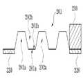
도 1a 내지 도 1d는 본 발명의 일실시예에 따른 연료전지용 공냉식 금속 분리판을 개략적으로 나타낸 것이다.1a to 1d schematically illustrate an air-cooled metal separator plate for a fuel cell according to an embodiment of the present invention.
본 발명에 따른 공냉식 금속 분리판은 채널부(210), 제1가스켓(220) 및 제2가스켓(230)을 포함한다.The air-cooled metal separator according to the present invention includes a
채널부(210)는 금속판(201)의 중앙부에, 전면(201a)으로부터 배면(201b)으로 돌출 형성되는 반응가스 채널(202a)과 상기 배면(201b)에 돌출된 반응가스 채널(202a) 사이에 형성되는 공기 유로(202b)를 포함한다.The
제1가스켓(220)은 반응가스 채널(202a)의 기밀성을 부여하기 위하여, 채널 부(210) 전면(201a)의 테두리에 연속적으로 형성된다.The
제2가스켓(230)은 공기 유로(202b)의 공기의 흐름이 이루어지면서도 적층시 금속 분리판의 지지를 위하여, 채널부(210) 배면(201b)의 테두리에 비연속적으로 형성된다.The
도 1a 내지 도 1d는 반응가스가 유동하는 금속 분리판의 길이 방향에 따른 폭 방향 단면을 나타낸 것이다.1A to 1D are cross-sectional views in a width direction along a length direction of a metal separator plate through which a reaction gas flows.
도 1a의 경우, 채널부(210) 양측 테두리의 전면(201a)에 제1가스켓(220)이 형성되어 있고, 채널부(210) 양측 테두리의 배면(201b)에 제2가스켓(230)이 형성되어 있다.In the case of FIG. 1A, a
도 1b 및 도 1c의 경우, 채널부(210) 양측 테두리의 전면(201a)에 제1가스켓(220)이 형성되어 있고, 채널부(210) 일측 테두리의 배면(201b)에만 제2가스켓(230)이 형성되어 있다.1B and 1C, the
도 1d의 경우, 채널부(210) 양측 테두리의 전면(201a)에 제1가스켓(220)이 형성되어 있고, 채널부(210) 양측 테두리의 배면(201b)에는 제2가스켓(230)이 형성되어 있지 않다.In the case of FIG. 1D, a
즉, 채널부(210) 양측 테두리의 전면(201a)에 형성되는 제1가스켓(220)은 기밀을 위한 것이므로, 금속 분리판의 길이 방향을 따라 연속적으로 형성되어 있어야 한다.That is, since the
반면, 채널부(210) 양측 테두리의 배면(201b)에 형성되는 제2가스켓(230)은 공냉식의 특성상 존재하지 않아도 무방하다. 그러나, 제2가스켓(230)이 전혀 형 성되어 있지 않을 경우, 연료전지 스택 제조를 위하여 금속 분리판과 막-전극 접합체를 순차적으로 적층할 때에 채널부의 테두리 부분의 지지가 이루어지지 않아 금속 분리판의 변형이 이루어질 수 있다. 따라서, 제2가스켓(230)은 채널부(210) 양측 테두리의 배면(201b)에 비연속적으로 형성되어, 공기 유로에서의 공기 유동을 방해하지 않으면서 금속 분리판을 지지하게 되는 것이다.On the other hand, the
이렇게 비연속적으로 형성되는 제2가스켓(230) 금속 분리판의 길이 방향을 따라 양측으로 대칭적으로 형성될 수 있으며, 금속 분리판의 길이 방향을 따라 양측으로 비대칭적으로 형성되어도 무방하다.The discontinuously formed
종래의 수냉식 금속 분리판은 연료전지 동작시 활성화 손실(activation loss), 양극에서의 환원 반응 및 주울 가열(Joule heating) 등의 원인으로 인하여 발생하는 열을 냉각하기 위하여 냉각수를 냉각수 채널로 계속해서 공급하여야 하였다. 그러나, 본 발명에 따른 공냉식 금속 분리판은 공기를 통해 냉각이 이루어지므로 냉각수를 공급하지 않아도 되며, 또한, 분리판 배면의 가스켓은 기밀성을 부여하기 위한 것이 아니라, 분리판을 지지하여 분리판의 변형을 방지하기 위한 목적에서 형성된다. 분리판 배면의 가스켓에서 비연속적 부분은 공기의 이동 통로가 된다.Conventional water-cooled metal separators continue to supply coolant to the coolant channel to cool the heat generated due to activation losses, reduction reactions at the anode and Joule heating during fuel cell operation. It should be. However, the air-cooled metal separator according to the present invention does not need to supply cooling water because the cooling is performed through air, and the gasket on the back of the separator is not intended to impart airtightness, but supports the separator to deform the separator. It is formed for the purpose of preventing. In the gasket on the back of the separator plate, the discontinuous portion becomes a passage for air.
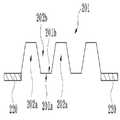
도 2a 및 도 2b는 본 발명의 일실시예에 따른 공냉식 금속 분리판의 전면 및 배면을 나타낸 것이다.Figures 2a and 2b shows the front and back of the air-cooled metal separator in accordance with an embodiment of the present invention.
먼저, 반응가스가 유동하는 공냉식 금속 분리판의 전면을 나타내는 도 2a 를 참조하면, 직사각형 형태의 금속판(310)의 중심부에 반응가스 채널(340) 및 공기 유로(345)를 포함하는 채널부가 형성되고, 채널부 주변의 테두리를 둘러싸는 제1가스켓(331)이 연속적으로 형성된다. 여기서, 도 2a 및 도 2b에서는 직사각형 형태의 금속판(310)의 장방향의 일부를 생략하였다.First, referring to FIG. 2A, which illustrates a front surface of an air-cooled metal separator plate through which a reaction gas flows, a channel part including a
반응가스 채널(340)은 스탬핑 공정에 의하여 금속판의 전면에서 배면으로 돌출하는 형태로 형성되며, 배면의 반응가스 채널(340)의 사이 부분에 공기 유로(345)가 형성되며, 반응가스 채널(340) 및 공기 유로(345)를 포함하여 채널부를 형성한다. 공기 유로(345)는 금속판(310)의 배면에 돌출된 반응가스 채널(340) 사이의 영역을 활용하여 형성되거나 또는 반응가스 채널(340)의 사이 부분이 금속판(310)의 전면으로 돌출하도록 스탬핑 공정에 의해 형성될 수 있다.The
상기 채널부의 구조를 통하여 반응가스는 금속판(310)의 전면 상에서 유동하고, 공기는 금속판의 배면 상에서 유동한다.Through the structure of the channel portion, the reaction gas flows on the front surface of the
다음으로, 공기가 유동하는 공냉식 금속 분리판의 배면을 나타내는 도 2b를 참조하면, 도 2a의 구조와 거의 동일하나, 채널부 양측에는 비연속적으로 제2가스켓(332)이 형성되어 있다. 이는 제1가스켓(331)의 경우 반응가스의 기밀을 위한 것이므로 연속적으로 형성되는 것이고, 제2가스켓(332)의 경우 기밀성을 요하지 않으면서 또한 분리판의 지지를 목적으로 형성되는 것이므로 비연속적으로 형성되는 것이다.Next, referring to FIG. 2B, which shows the rear surface of the air-cooled metal separator plate through which air flows, the
도 2b에는 비연속적으로 형성되는 제2가스켓(332)이 채널부 양측으로 대칭형으로 형성되어 있는 예를 나타내었으나, 비대칭형으로 형성될 수도 있다.In FIG. 2B, an example in which the
한편, 도 2a 및 도 2b를 참조하면, 채널부의 길이방향의 일측에는 반응가스를 채널부의 반응가스 채널(340)로 도입하는 반응가스 유입 매니폴드 및 채널부의 길이방향의 타측에는 반응가스 채널(340)로부터 반응가스를 배출하기 위한 반응가스 배출 매니폴드를 포함하는 반응가스 매니폴드가 각각 개구된 형태로 형성되어 있다. 본 발명은 공냉식 금속 분리판이므로, 종래와 같은 냉각수 유입 매니폴드 혹은 냉각수 배출 매니폴드를 요하지 않는다.2A and 2B, a reaction gas inlet manifold for introducing a reaction gas into a
구체적으로 반응가스 유입 매니폴드는 산소 유입 매니폴드(320) 및 수소 유입 매니폴드(328)가 분할 형성되어 있으며, 산소 유입 매니폴드(320) 또는 수소 유입 매니폴드(328)와 채널부 사이에는 반응가스 유입홀(325)이 형성된다. 마찬가지로, 반응가스 배출 매니폴드는 산소 배출 매니폴드(360) 및 수소 배출 매니폴드(368)가 분할 형성되어 있으며, 수소 배출 매니폴드(368) 또는 산소 배출 매니폴드(360)와 채널부 사이에는 반응가스 배출홀(365) 이 형성된다.Specifically, the reaction gas inlet manifold is divided into the
상기 반응가스 유입 매니폴드에 형성되는 산소 유입 매니폴드(320)와 수소 유입 매니폴드(328)는 금속판(310)에 미리 분할된 개구부를 형성하고, 이를 이용하여 분할 형성할 수 있으며, 또한 각각의 매니폴드 형성을 위한 일체화된 고분자 틀 구조에 의해 분할 형성될 수 있다. 이는 그리고 반응가스 배출 매니폴드에 형성되는 산소 배출 매니폴드(360)와 수소 배출 매니폴드(368)의 분할 형성에도 마찬가지로 적용할 수 있다.The
또한, 반응가스 유입 매니폴드와 반응가스 배출 매니폴드의 전면 및 배면의 테두리에는 산소 가스 및 수소 가스를 밀봉하기 위하여 제3가스켓(333)이 연속 적으로 형성되어 있다. 제3가스켓(333)은 제1가스켓(331)이나 제2가스켓(332)와 동일한 재질로 형성될 수 있으며, 가스켓 형성을 위한 사출 성형시 제1가스켓(331)이나 제2가스켓(332)와 동시에 형성될 수 있다.In addition, a
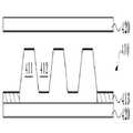
도 3a 내지 도 3f는 본 발명에 따른 공냉식 금속 분리판이 적용된 연료전지 스택의 예를 나타낸 것이다.3A to 3F show examples of a fuel cell stack to which an air-cooled metal separator according to the present invention is applied.
도 3a 내지 3d는 하나의 공냉식 금속 분리판과 막-전극 접합체(Membrane Electrode Assembly; MEA)가 순차적으로 적층되어 형성되는 연료전지 스택을 나타낸 것이고, 도 3e 및 도 3f는 공냉식 금속 분리판 2개가 각각의 전면이 대향하는 형태로 접합되어 있는 분리판 구조물과 막-전극 접합체(MEA)가 순차적으로 적층되어 형성되는 연료전지 스택을 나타낸 것이다.3A to 3D illustrate a fuel cell stack in which one air-cooled metal separator and a membrane-electrode assembly (MEA) are sequentially stacked, and FIGS. 3E and 3F show two air-cooled metal separators, respectively. A fuel cell stack is formed by sequentially stacking a separator structure and a membrane-electrode assembly (MEA), which are joined in opposing forms.
도 3a 및 3b를 참조하면, 연료전지 스택은 금속 분리판(410)과 막-전극 접합체(420)가 순차적으로 적층되어 형성된다. 금속 분리판(410)에서 반응가스 및 공기가 유동하는 채널부의 테두리에는 가스켓이 형성되는데, 분리판(410)의 전면에는 연속적인 제1가스켓(413)이 형성되어 있고, 분리판(410)의 배면에는 비연속적인 제2가스켓(414)이 형성되어 있다. 도 3a에는 제2가스켓(414)가 형성된 것을, 도 3b에는 제2가스켓(414)이 형성되지 않은 것을 의미한다.3A and 3B, a fuel cell stack is formed by sequentially stacking a
이는 전술한 바와 같이, 분리판의 전면에 형성되는 제1가스켓(413)의 경우에는 반응가스 채널(411)에 기밀성을 부여하여, 반응가스를 밀봉하기 위한 것이므로 연속적으로 형성되는 것이며, 분리판의 배면에 형성되는 제2가스켓(414)의 경우 에는 공기 유로(412)의 개방을 통한 공기 유동에 방해를 하지 않으면서 막-전극 접합체(420)에 대한 지지 역할을 하기 위하여 비연속적으로 형성되는 것이다.As described above, in the case of the
도 3a 및 도 3b의 경우에는 제1가스켓(413)에 의해 반응가스 채널(411) 사이에 통로가 존재하는 예가 나타나 있으며, 도 3c 및 도 3d의 경우에는 제1가스켓(413)의 두께를 최소한으로 줄이는 것을 통하여 반응가스 채널(411) 사이에 통로가 존재하지 않는 예가 나타나 있다.3A and 3B illustrate an example in which passages exist between the
반응가스 채널(411) 사이에 통로를 존재하지 않는 것은 반응가스 채널(411) 형성을 위한 금속판의 전면에서 배면으로의 스탬핑 공정 이외에, 공기 유로 형성을 위한 배면에서 전면으로의 스탬핑을 통하여도 이루어질 수 있다. 반응가스 채널(411) 사이에 통로가 존재하거나 각각의 반응가스 채널(411)을 밀폐하는 것은 금속 분리판의 사용 환경에 따라서 달라질 수 있다.The absence of a passage between the
도면에는 도시되지 않았으나, 금속 분리판(410)의 전면과 막-전극 접합체(420) 사이에는 반응가스 채널(411)을 통하여 유동하는 반응가스를 막-전극 접합체(420) 표면으로 고르게 분산시켜주는 다공성 매체인 기체 확산층(Gas Diffusion Layer)이 더 포함될 수 있다.Although not shown in the drawing, the reaction gas flowing through the
도 3e 및 도 3f는 공냉식 금속 분리판 2개(410a,410b)가 각각의 전면이 대향하는 형태로 접합되어 있는 분리판 구조물과 막-전극 접합체(420)가 순차적으로 적층되어 형성되는 연료전지 스택을 나타낸 것이다. 도 3e의 경우에는 제1가스켓(413)에 의해 2개의 금속 분리판(410)의 접합에 의해 형성되는 반응가스 채널(411)들 사이에 통로가 존재하는 예가 나타나 있으며, 도 3f의 경우에는 제1가스 켓(413)의 두께를 최소한으로 줄이는 것을 통하여 반응가스 채널(411) 사이에 통로가 존재하지 않는 예가 나타나 있다.3E and 3F illustrate a fuel cell stack in which two air-cooled
반응가스 채널(411) 사이에 통로를 존재하지 않는 것은 전술한 바와 같이, 가스켓의 두께에 의하여 이루어질 수 있으며, 또한 반응가스 채널(411) 형성을 위한 금속판의 전면에서 배면으로의 스탬핑 공정 이외에, 공기 유로 형성을 위한 배면에서 전면으로의 스탬핑을 통하여도 이루어질 수 있다.The absence of a passage between the
반응가스 채널(411) 사이에 통로가 존재하거나 각각의 반응가스 채널(411)을 밀폐하는 것은 금속 분리판의 사용 환경에 따라서 달라질 수 있다.The presence of a passage between the
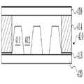
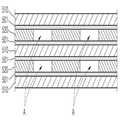
도 4는 다층의 공냉식 금속 분리판 구조체의 예를 나타내는 측면도이다.4 is a side view illustrating an example of a multilayer air-cooled metal separator structure.
도 4를 참조하면, 도시된 다층의 공냉식 금속 분리판 구조체는 연속적인 제1가스켓(510), 금속 본체(501), 비연속적인 제2가스켓(520), 금속 본체(501), 연속적인 제1가스켓(510), 금속 본체(501), 비연속적인 제2가스켓(520), 금속본체(501) 및 연속적인 제1가스켓(510)이 하부로부터 순차적으로 형성되어 있다.Referring to FIG. 4, the illustrated multi-layer air-cooled metal separator structure includes a continuous
여기서, 제1가스켓(510)은 전술한 바와 같이, 채널부에 기밀성을 부여하기 위하여 연속적으로 형성된다. 반면, 제2가스켓(520)은 제1가스켓(510)과는 달리, 비연속적으로 형성되어 하나의 제2가스켓과 다른 제2가스켓 사이에 유로(A)를 제공하게 된다.As described above, the
이에 따라, 제2가스켓(520)이 형성되어 있는 부분은 분리판들을 지지하는 역할을 하게 되고, 제2가스켓(520)이 형성되지 않은 부분은 공기가 유동할 수 있는 유로의 역할을 하게 된다.Accordingly, the portion in which the
이러한 다층 구조체는 4개의 금속 분리판을 접합함으로써 형성할 수 있는데, 이 경우, 하나의 금속 분리판의 제1가스켓과 다른 하나의 금속 분리판의 제1가스켓을 접합하고, 하나의 금속 분리판의 제2가스켓과 다른 하나의 금속 분리판의 제2가스켓을 접합하게 된다.Such a multi-layer structure can be formed by joining four metal separator plates, in which case, the first gasket of one metal separator plate and the first gasket of the other metal separator plate are joined together, and The second gasket is joined to the second gasket of the other metal separator plate.
상술한 바와 같이, 본 발명에 따른 연료전지용 공냉식 금속 분리판은 연료전지 구동시 발생하는 열을 냉각하기 위한 냉각수를 필요로 하지 않아, 연료전지 제조 비용 및 구동 비용을 절감할 수 있는 효과가 있다.As described above, the air-cooled metal separator plate for fuel cells according to the present invention does not require a cooling water for cooling the heat generated when driving the fuel cell, thereby reducing the fuel cell manufacturing cost and driving cost.
또한 본 발명에 따른 공냉식 금속 분리판과 막-전극 접합체(MEA)를 순차적으로 적층한 연료전지 스택은 상기 공냉식 금속 분리판의 공기 유동면에 비연속적 가스켓이 배치되어 금속 본체의 변형을 방지할 수 있고, 또한 가스켓의 비연속적 부분을 통하여 공기의 이동 통로를 확보할 수 있게 된다. 이는 종래의 수냉식 금속 분리판의 가스켓 구조를 변경함으로써 쉽게 구현할 수 있다.In addition, the fuel cell stack sequentially stacking the air-cooled metal separator and the membrane-electrode assembly (MEA) according to the present invention may have a discontinuous gasket disposed on the air flow surface of the air-cooled metal separator to prevent deformation of the metal body. In addition, it is possible to secure the passage of the air through the discontinuous portion of the gasket. This can be easily accomplished by changing the gasket structure of a conventional water-cooled metal separator.
본 발명은 도면에 도시된 실시예를 참고로 하여 설명되었으나, 이는 예시적인 것에 불과하며, 당해 기술이 속하는 분야에서 통상의 지식을 가진 자라면 이로부터 다양한 변형 및 균등한 타 실시예가 가능하다는 점을 이해할 것이다.Although the present invention has been described with reference to the embodiments shown in the drawings, this is merely exemplary, and those skilled in the art to which the art belongs can make various modifications and other equivalent embodiments therefrom. Will understand.
따라서, 본 발명의 진정한 기술적 보호범위는 아래의 특허청구범위에 의해서 정하여져야 할 것이다.Therefore, the true technical protection scope of the present invention will be defined by the claims below.
도 1a 내지 도 1d는 본 발명의 일실시예에 따른 연료전지용 공냉식 금속 분리판을 개략적으로 나타낸 것이다.1a to 1d schematically illustrate an air-cooled metal separator plate for a fuel cell according to an embodiment of the present invention.
도 2a 및 도 2b는 본 발명의 일실시예에 따른 공냉식 금속 분리판의 전면 및 배면을 나타낸 것이다.Figures 2a and 2b shows the front and back of the air-cooled metal separator in accordance with an embodiment of the present invention.
도 3a 내지 도 3f는 본 발명에 따른 공냉식 금속 분리판이 적용된 연료전지 스택의 예를 나타낸 것이다.3A to 3F show examples of a fuel cell stack to which an air-cooled metal separator according to the present invention is applied.
도 4는 다층의 공냉식 금속 분리판 구조체의 예를 나타내는 측면도이다.4 is a side view illustrating an example of a multilayer air-cooled metal separator structure.
Claims (7)
Translated fromKoreanPriority Applications (6)
| Application Number | Priority Date | Filing Date | Title |
|---|---|---|---|
| KR1020090071019AKR100938023B1 (en) | 2009-07-31 | 2009-07-31 | Air cooled metal separator for fuel cell and fuel cell stack using the air cooled metal separator |
| PCT/KR2009/004356WO2011013868A1 (en) | 2009-07-31 | 2009-08-04 | Air-cooled metal separator for fuel cell and fuel cell stack using same |
| CN200980160733.9ACN102473928B (en) | 2009-07-31 | 2009-08-04 | Air-cooled metal separator plate for fuel cell and fuel cell stack using the same |
| EP09847856.3AEP2461403B1 (en) | 2009-07-31 | 2009-08-04 | Air-cooled metal separator for fuel cell and fuel cell stack using same |
| JP2012522734AJP5687272B2 (en) | 2009-07-31 | 2009-08-04 | Air-cooled metal separator for fuel cells |
| US13/387,929US20120129072A1 (en) | 2009-07-31 | 2009-08-04 | Air-cooled metal separator for fuel cell and fuel cell stack using same |
Applications Claiming Priority (1)
| Application Number | Priority Date | Filing Date | Title |
|---|---|---|---|
| KR1020090071019AKR100938023B1 (en) | 2009-07-31 | 2009-07-31 | Air cooled metal separator for fuel cell and fuel cell stack using the air cooled metal separator |
Publications (1)
| Publication Number | Publication Date |
|---|---|
| KR100938023B1true KR100938023B1 (en) | 2010-01-21 |
Family
ID=41810099
Family Applications (1)
| Application Number | Title | Priority Date | Filing Date |
|---|---|---|---|
| KR1020090071019AActiveKR100938023B1 (en) | 2009-07-31 | 2009-07-31 | Air cooled metal separator for fuel cell and fuel cell stack using the air cooled metal separator |
Country Status (6)
| Country | Link |
|---|---|
| US (1) | US20120129072A1 (en) |
| EP (1) | EP2461403B1 (en) |
| JP (1) | JP5687272B2 (en) |
| KR (1) | KR100938023B1 (en) |
| CN (1) | CN102473928B (en) |
| WO (1) | WO2011013868A1 (en) |
Cited By (7)
| Publication number | Priority date | Publication date | Assignee | Title |
|---|---|---|---|---|
| KR101459961B1 (en)* | 2013-10-24 | 2014-11-07 | 현대하이스코 주식회사 | Metal separator for air cooling type fuel cell stack having open type air channel and air cooling type fuel cell stack having the same |
| KR101509949B1 (en) | 2013-10-24 | 2015-04-07 | 현대하이스코 주식회사 | Metal separator for fuel cell stack improving reaction gas supply and humidification performance and fuel cell stack having the same |
| WO2015060517A1 (en)* | 2013-10-24 | 2015-04-30 | 현대하이스코 주식회사 | Metal separation plate for fuel cell stack and fuel cell stack having same |
| KR20160055550A (en)* | 2014-11-10 | 2016-05-18 | 한국타이어 주식회사 | Fuel Cell Separator |
| WO2017146359A1 (en)* | 2016-02-23 | 2017-08-31 | (주)엘지하우시스 | Fuel cell separator plate and fuel cell stack having same |
| KR20190068151A (en)* | 2017-12-08 | 2019-06-18 | 현대자동차주식회사 | Gasket of metal air battery |
| KR20220092062A (en) | 2020-12-24 | 2022-07-01 | 현대자동차주식회사 | Separator assembly for air cooled fuel cell and Fuel cell stack including the same |
Families Citing this family (5)
| Publication number | Priority date | Publication date | Assignee | Title |
|---|---|---|---|---|
| KR101806620B1 (en)* | 2015-09-23 | 2017-12-07 | 현대자동차주식회사 | Fuel cell stack |
| KR102071906B1 (en) | 2016-12-02 | 2020-01-31 | 주식회사 엘지화학 | Separator, and Fuel cell stack comprising the same |
| JP7600854B2 (en) | 2021-05-14 | 2024-12-17 | トヨタ自動車株式会社 | Fuel Cells |
| KR20230095602A (en)* | 2021-12-22 | 2023-06-29 | 현대자동차주식회사 | Separator unit for fuel cell and Unit cell for fuel cell including same |
| CN113964362B (en)* | 2021-12-23 | 2022-03-08 | 国家电投集团氢能科技发展有限公司 | Frame structure and electrochemical cell device having the same |
Citations (4)
| Publication number | Priority date | Publication date | Assignee | Title |
|---|---|---|---|---|
| US20010033956A1 (en) | 2000-02-11 | 2001-10-25 | Texas A&M University System | Fuel cell with monolithic flow field-bipolar plate assembly and method for making and cooling a fuel cell stack |
| JP2006179404A (en)* | 2004-12-24 | 2006-07-06 | Ebara Corp | Air cooling type fuel cell power generating device |
| JP2008146843A (en)* | 2006-12-06 | 2008-06-26 | Kurimoto Ltd | Solid polymer fuel battery |
| US20090092866A1 (en) | 2004-12-21 | 2009-04-09 | Nissan Motor Co., Ltd. | Startup method for fuel cell stack structure, temperature control method for fuel cell stack structure, and fuel cell stack structure |
Family Cites Families (10)
| Publication number | Priority date | Publication date | Assignee | Title |
|---|---|---|---|---|
| US5424144A (en)* | 1993-10-21 | 1995-06-13 | M-C Power Corporation | One piece separator plate with insert ring step design |
| JP3540491B2 (en)* | 1996-03-07 | 2004-07-07 | 政廣 渡辺 | Fuel cell, electrolytic cell and cooling / dehumidifying method thereof |
| US7226688B2 (en)* | 1999-09-10 | 2007-06-05 | Honda Motor Co., Ltd. | Fuel cell |
| JP4448703B2 (en)* | 2004-01-30 | 2010-04-14 | 本田技研工業株式会社 | In-vehicle fuel cell stack operation method |
| US20080050629A1 (en)* | 2006-08-25 | 2008-02-28 | Bruce Lin | Apparatus and method for managing a flow of cooling media in a fuel cell stack |
| KR100821389B1 (en)* | 2006-09-07 | 2008-04-11 | 현대자동차주식회사 | Structure for Improving Stackability of Metal Separation Plate for Fuel Cell Stack |
| WO2008047989A1 (en)* | 2006-10-16 | 2008-04-24 | Hyundai Hysco | Metal separator for fuel cell and fuel cell stack having the same |
| DK176957B1 (en)* | 2007-07-18 | 2010-07-26 | Serenergy As | Improvements in gaskets and bipolar plates for PEM fuel cells |
| CN101308936A (en)* | 2008-06-03 | 2008-11-19 | 大连工业大学 | Direct Air Cooled Fuel Cells |
| CN101420037B (en)* | 2008-12-10 | 2011-05-18 | 新源动力股份有限公司 | A metal bipolar plate for a proton exchange membrane fuel cell |
- 2009
- 2009-07-31KRKR1020090071019Apatent/KR100938023B1/enactiveActive
- 2009-08-04USUS13/387,929patent/US20120129072A1/ennot_activeAbandoned
- 2009-08-04JPJP2012522734Apatent/JP5687272B2/enactiveActive
- 2009-08-04CNCN200980160733.9Apatent/CN102473928B/enactiveActive
- 2009-08-04WOPCT/KR2009/004356patent/WO2011013868A1/enactiveApplication Filing
- 2009-08-04EPEP09847856.3Apatent/EP2461403B1/enactiveActive
Patent Citations (4)
| Publication number | Priority date | Publication date | Assignee | Title |
|---|---|---|---|---|
| US20010033956A1 (en) | 2000-02-11 | 2001-10-25 | Texas A&M University System | Fuel cell with monolithic flow field-bipolar plate assembly and method for making and cooling a fuel cell stack |
| US20090092866A1 (en) | 2004-12-21 | 2009-04-09 | Nissan Motor Co., Ltd. | Startup method for fuel cell stack structure, temperature control method for fuel cell stack structure, and fuel cell stack structure |
| JP2006179404A (en)* | 2004-12-24 | 2006-07-06 | Ebara Corp | Air cooling type fuel cell power generating device |
| JP2008146843A (en)* | 2006-12-06 | 2008-06-26 | Kurimoto Ltd | Solid polymer fuel battery |
Cited By (13)
| Publication number | Priority date | Publication date | Assignee | Title |
|---|---|---|---|---|
| US10186717B2 (en) | 2013-10-24 | 2019-01-22 | Hyundai Steel Company | Metal separation plate for fuel cell stack and fuel cell stack having the same |
| KR101509949B1 (en) | 2013-10-24 | 2015-04-07 | 현대하이스코 주식회사 | Metal separator for fuel cell stack improving reaction gas supply and humidification performance and fuel cell stack having the same |
| WO2015060517A1 (en)* | 2013-10-24 | 2015-04-30 | 현대하이스코 주식회사 | Metal separation plate for fuel cell stack and fuel cell stack having same |
| KR101459961B1 (en)* | 2013-10-24 | 2014-11-07 | 현대하이스코 주식회사 | Metal separator for air cooling type fuel cell stack having open type air channel and air cooling type fuel cell stack having the same |
| GB2533755A (en)* | 2013-10-24 | 2016-06-29 | Hyundai Steel Co | Metal separation plate for fuel cell stack and fuel cell stack having same |
| GB2533755B (en)* | 2013-10-24 | 2021-05-05 | Hyundai Steel Co | Metal separation plate for fuel cell stack and fuel cell stack having same |
| KR20160055550A (en)* | 2014-11-10 | 2016-05-18 | 한국타이어 주식회사 | Fuel Cell Separator |
| KR101698584B1 (en)* | 2014-11-10 | 2017-02-01 | 한국타이어 주식회사 | Fuel Cell Separator |
| WO2017146359A1 (en)* | 2016-02-23 | 2017-08-31 | (주)엘지하우시스 | Fuel cell separator plate and fuel cell stack having same |
| KR20190068151A (en)* | 2017-12-08 | 2019-06-18 | 현대자동차주식회사 | Gasket of metal air battery |
| KR102540508B1 (en)* | 2017-12-08 | 2023-06-05 | 현대자동차주식회사 | Gasket of metal air battery |
| KR20220092062A (en) | 2020-12-24 | 2022-07-01 | 현대자동차주식회사 | Separator assembly for air cooled fuel cell and Fuel cell stack including the same |
| US11652221B2 (en) | 2020-12-24 | 2023-05-16 | Hyundai Motor Company | Separator assembly for air cooled fuel cell and fuel cell stack including the same |
Also Published As
| Publication number | Publication date |
|---|---|
| EP2461403B1 (en) | 2016-07-27 |
| JP2013500567A (en) | 2013-01-07 |
| EP2461403A1 (en) | 2012-06-06 |
| CN102473928B (en) | 2016-03-30 |
| JP5687272B2 (en) | 2015-03-18 |
| US20120129072A1 (en) | 2012-05-24 |
| WO2011013868A1 (en) | 2011-02-03 |
| CN102473928A (en) | 2012-05-23 |
| EP2461403A4 (en) | 2014-01-22 |
Similar Documents
| Publication | Publication Date | Title |
|---|---|---|
| KR100938023B1 (en) | Air cooled metal separator for fuel cell and fuel cell stack using the air cooled metal separator | |
| EP1239530B1 (en) | Solid polymer electrolyte fuel cell assembly, fuel cell stack, and method of supplying reaction gas in the fuel cell assembly | |
| CN102136585B (en) | Fuel cells | |
| US7022430B2 (en) | Compact fuel cell with improved fluid supply | |
| EP2980904A1 (en) | Fuel battery | |
| JP2000504140A (en) | Fluid-cooled fuel cell with distribution passage | |
| US8062807B2 (en) | Fuel cell | |
| US7226688B2 (en) | Fuel cell | |
| CN104900894A (en) | Metal pole plate of fuel battery, metal bipolar plate of fuel battery and fuel battery | |
| CN101529626B (en) | Metal separators for fuel cells | |
| JP5436670B2 (en) | Metal separator for fuel cell and fuel cell stack provided with the same | |
| US8153288B2 (en) | Fuel cell and fuel cell stack | |
| US7846613B2 (en) | Fuel cell with separator having a ridge member | |
| US8053125B2 (en) | Fuel cell having buffer and seal for coolant | |
| CN107210459B (en) | Bipolar plates and the fuel cell with this bipolar plates | |
| KR20130027940A (en) | Metal seperator for fuel cell including and fuel cell stack having the same | |
| CN115799560B (en) | Bipolar plate structure and battery stack | |
| US20230327142A1 (en) | Separator for fuel cell and fuel cell stack | |
| KR101141495B1 (en) | Fuel cell stack having convex coolant guideline | |
| JP2007141574A (en) | Fuel cell stack | |
| CN113948733A (en) | Closed cathode air-cooled fuel cell unit | |
| JP2006032007A (en) | Fuel cell | |
| JP2013206636A (en) | Fuel cell | |
| JP2017147094A (en) | Fuel cell |
Legal Events
| Date | Code | Title | Description |
|---|---|---|---|
| A201 | Request for examination | ||
| PA0109 | Patent application | Patent event code:PA01091R01D Comment text:Patent Application Patent event date:20090731 | |
| PA0201 | Request for examination | ||
| A302 | Request for accelerated examination | ||
| PA0302 | Request for accelerated examination | Patent event date:20090819 Patent event code:PA03022R01D Comment text:Request for Accelerated Examination Patent event date:20090731 Patent event code:PA03021R01I Comment text:Patent Application | |
| E701 | Decision to grant or registration of patent right | ||
| PE0701 | Decision of registration | Patent event code:PE07011S01D Comment text:Decision to Grant Registration Patent event date:20091028 | |
| GRNT | Written decision to grant | ||
| PR0701 | Registration of establishment | Comment text:Registration of Establishment Patent event date:20100113 Patent event code:PR07011E01D | |
| PR1002 | Payment of registration fee | Payment date:20100113 End annual number:3 Start annual number:1 | |
| PG1601 | Publication of registration | ||
| FPAY | Annual fee payment | Payment date:20130102 Year of fee payment:4 | |
| PR1001 | Payment of annual fee | Payment date:20130102 Start annual number:4 End annual number:4 | |
| FPAY | Annual fee payment | Payment date:20140102 Year of fee payment:5 | |
| PR1001 | Payment of annual fee | Payment date:20140102 Start annual number:5 End annual number:5 | |
| FPAY | Annual fee payment | Payment date:20150102 Year of fee payment:6 | |
| PR1001 | Payment of annual fee | Payment date:20150102 Start annual number:6 End annual number:6 | |
| FPAY | Annual fee payment | Payment date:20160113 Year of fee payment:7 | |
| PR1001 | Payment of annual fee | Payment date:20160113 Start annual number:7 End annual number:7 | |
| FPAY | Annual fee payment | Payment date:20161228 Year of fee payment:8 | |
| PR1001 | Payment of annual fee | Payment date:20161228 Start annual number:8 End annual number:8 | |
| FPAY | Annual fee payment | Payment date:20180103 Year of fee payment:9 | |
| PR1001 | Payment of annual fee | Payment date:20180103 Start annual number:9 End annual number:9 | |
| FPAY | Annual fee payment | Payment date:20200106 Year of fee payment:11 | |
| PR1001 | Payment of annual fee | Payment date:20200106 Start annual number:11 End annual number:11 | |
| PR1001 | Payment of annual fee | Payment date:20201209 Start annual number:12 End annual number:12 | |
| PR1001 | Payment of annual fee | Payment date:20211229 Start annual number:13 End annual number:13 | |
| PR1001 | Payment of annual fee | Payment date:20221205 Start annual number:14 End annual number:14 | |
| PR1001 | Payment of annual fee | Payment date:20231226 Start annual number:15 End annual number:15 |