KR100936839B1 - Liquid storage container and liquid supply device - Google Patents
Liquid storage container and liquid supply deviceDownload PDFInfo
- Publication number
- KR100936839B1 KR100936839B1KR1020097014919AKR20097014919AKR100936839B1KR 100936839 B1KR100936839 B1KR 100936839B1KR 1020097014919 AKR1020097014919 AKR 1020097014919AKR 20097014919 AKR20097014919 AKR 20097014919AKR 100936839 B1KR100936839 B1KR 100936839B1
- Authority
- KR
- South Korea
- Prior art keywords
- liquid
- pressure
- air
- ink
- attachment
- Prior art date
- Legal status (The legal status is an assumption and is not a legal conclusion. Google has not performed a legal analysis and makes no representation as to the accuracy of the status listed.)
- Expired - Fee Related
Links
Images


Classifications
- B—PERFORMING OPERATIONS; TRANSPORTING
- B41—PRINTING; LINING MACHINES; TYPEWRITERS; STAMPS
- B41J—TYPEWRITERS; SELECTIVE PRINTING MECHANISMS, i.e. MECHANISMS PRINTING OTHERWISE THAN FROM A FORME; CORRECTION OF TYPOGRAPHICAL ERRORS
- B41J2/00—Typewriters or selective printing mechanisms characterised by the printing or marking process for which they are designed
- B41J2/005—Typewriters or selective printing mechanisms characterised by the printing or marking process for which they are designed characterised by bringing liquid or particles selectively into contact with a printing material
- B41J2/01—Ink jet
- B41J2/17—Ink jet characterised by ink handling
- B41J2/175—Ink supply systems ; Circuit parts therefor
- B41J2/17503—Ink cartridges
- B41J2/1752—Mounting within the printer
- B41J2/17523—Ink connection
- B—PERFORMING OPERATIONS; TRANSPORTING
- B41—PRINTING; LINING MACHINES; TYPEWRITERS; STAMPS
- B41J—TYPEWRITERS; SELECTIVE PRINTING MECHANISMS, i.e. MECHANISMS PRINTING OTHERWISE THAN FROM A FORME; CORRECTION OF TYPOGRAPHICAL ERRORS
- B41J2/00—Typewriters or selective printing mechanisms characterised by the printing or marking process for which they are designed
- B41J2/005—Typewriters or selective printing mechanisms characterised by the printing or marking process for which they are designed characterised by bringing liquid or particles selectively into contact with a printing material
- B41J2/01—Ink jet
- B41J2/17—Ink jet characterised by ink handling
- B41J2/175—Ink supply systems ; Circuit parts therefor
- B41J2/17503—Ink cartridges
- B41J2/1752—Mounting within the printer
- B—PERFORMING OPERATIONS; TRANSPORTING
- B41—PRINTING; LINING MACHINES; TYPEWRITERS; STAMPS
- B41J—TYPEWRITERS; SELECTIVE PRINTING MECHANISMS, i.e. MECHANISMS PRINTING OTHERWISE THAN FROM A FORME; CORRECTION OF TYPOGRAPHICAL ERRORS
- B41J2/00—Typewriters or selective printing mechanisms characterised by the printing or marking process for which they are designed
- B41J2/005—Typewriters or selective printing mechanisms characterised by the printing or marking process for which they are designed characterised by bringing liquid or particles selectively into contact with a printing material
- B41J2/01—Ink jet
- B41J2/17—Ink jet characterised by ink handling
- B41J2/175—Ink supply systems ; Circuit parts therefor
- B41J2/17503—Ink cartridges
- B41J2/17553—Outer structure
- B—PERFORMING OPERATIONS; TRANSPORTING
- B41—PRINTING; LINING MACHINES; TYPEWRITERS; STAMPS
- B41J—TYPEWRITERS; SELECTIVE PRINTING MECHANISMS, i.e. MECHANISMS PRINTING OTHERWISE THAN FROM A FORME; CORRECTION OF TYPOGRAPHICAL ERRORS
- B41J2/00—Typewriters or selective printing mechanisms characterised by the printing or marking process for which they are designed
- B41J2/005—Typewriters or selective printing mechanisms characterised by the printing or marking process for which they are designed characterised by bringing liquid or particles selectively into contact with a printing material
- B41J2/01—Ink jet
- B41J2/17—Ink jet characterised by ink handling
- B41J2/175—Ink supply systems ; Circuit parts therefor
- B41J2/17503—Ink cartridges
- B41J2/17556—Means for regulating the pressure in the cartridge
- B—PERFORMING OPERATIONS; TRANSPORTING
- B41—PRINTING; LINING MACHINES; TYPEWRITERS; STAMPS
- B41J—TYPEWRITERS; SELECTIVE PRINTING MECHANISMS, i.e. MECHANISMS PRINTING OTHERWISE THAN FROM A FORME; CORRECTION OF TYPOGRAPHICAL ERRORS
- B41J2/00—Typewriters or selective printing mechanisms characterised by the printing or marking process for which they are designed
- B41J2/005—Typewriters or selective printing mechanisms characterised by the printing or marking process for which they are designed characterised by bringing liquid or particles selectively into contact with a printing material
- B41J2/01—Ink jet
- B41J2/17—Ink jet characterised by ink handling
- B41J2/175—Ink supply systems ; Circuit parts therefor
- B41J2/17503—Ink cartridges
- B41J2/17513—Inner structure
- B41J2002/17516—Inner structure comprising a collapsible ink holder, e.g. a flexible bag
Landscapes
- Ink Jet (AREA)
Abstract
Translated fromKoreanDescription
Translated fromKorean본 발명은 액체 분사 장치에 있어서 이용된 경우에 바람직한 어태치먼트 및 액체 공급 장치에 관한 것이다. 또한, 본 발명은 액체 수납 용기 및 액체 공급 장치에 관한 것이고, 특히 예를 들면 잉크젯 기록 장치 등의 액체 분사 장치에 있어서의 액체 카트리지의 대신에 장착해서 사용할 수 있는 동시에, 외부로부터의 잉크 등의 액체의 보충이 가능한 액체 수납 용기 및 액체 공급 장치에 관한 것이다.The present invention relates to a preferred attachment and liquid supply device when used in a liquid ejection device. Furthermore, the present invention relates to a liquid storage container and a liquid supply device, and in particular, it can be used in place of a liquid cartridge in a liquid ejection device such as, for example, an inkjet recording device, and at the same time, liquid such as ink from the outside. It relates to a liquid storage container and a liquid supply device that can be supplemented.
예컨대, 잉크젯 기록 장치(액체 분사 장치)는 일반적으로 캐리지상에 탑재되어서 기록 용지의 폭 방향으로 이동하는 잉크젯식 기록 헤드(액체 분사부)와, 기록 용지를 기록 헤드의 이동 방향에 대하여 직교하는 방향에 상대적으로 이동시키는 종이 피더 기구를 구비하고 있고, 인쇄 데이터에 근거해서 기록 헤드에 의해 잉크 방울을 토출시킴으로써, 기록 용지에 대하여 기록을 실행하게 되어 있다.For example, an inkjet recording apparatus (liquid ejection apparatus) is generally mounted on a carriage and moves in the width direction of the recording sheet, and the inkjet recording head (liquid ejection section) and the direction in which the recording sheet is orthogonal to the moving direction of the recording head. And a paper feeder mechanism for moving relative to each other, and recording is performed on the recording paper by ejecting ink droplets by the recording head based on the print data.
이 종류의 잉크젯 기록 장치중, 예를 들면 오피스 대상 또는 업무용에 제공되는 잉크젯 기록 장치에서는, 비교적 대량인 인쇄에 대응시키기 위해서, 대용량의 카트리지를 배비(配備)할 필요가 생기고 있다. 이 때문에, 기록 헤드가 탑재된 캐 리지상에 소용량의 서브 탱크를 배치하고, 카트리지로서의 메인 탱크를, 예를 들면 장치 본체의 측부에 마련한 장착부(카트리지 홀더)에 장전하고, 각 메인 탱크로부터 각 서브 탱크에 대하여 잉크 튜브를 거쳐서 각각 잉크를 공급하고, 또한 각 서브 탱크로부터 각각 기록 헤드에 대하여 잉크를 공급하도록 구성한 오프 캐리지식의 기록 장치가 알려져 있다.Among inkjet recording apparatuses of this kind, for example, inkjet recording apparatuses provided for office objects or for business use, it is necessary to arrange a large capacity cartridge in order to cope with a relatively large amount of printing. For this reason, a small-capacity sub tank is disposed on the carriage on which the recording head is mounted, and the main tank as a cartridge is loaded into a mounting portion (cartridge holder) provided, for example, on the side of the main body of the apparatus, and each sub tank from each main tank. Background Art An off-carriage recording apparatus is known in which ink is supplied to a tank via an ink tube, and ink is supplied from each sub tank to a recording head, respectively.
그런데, 최근에는 큰 지면에 대하여 인쇄를 실행할 수 있게, 캐리지의 주사 거리가 긴 대형의 기록 장치가 요구되고 있다. 이러한 기록 장치에 있어서는, 스루풋을 향상시키기 위해서, 기록 헤드의 다노즐화가 도모되고 있다.In recent years, however, there has been a demand for a large recording apparatus having a long scanning distance of the carriage so that printing can be performed on a large sheet of paper. In such a recording apparatus, in order to improve the throughput, the recording head has been multi-nosed.
또한, 스루풋을 향상시키기 위해서, 인쇄를 실행하면서 메인 탱크로부터, 캐리지에 탑재된 각 서브 탱크에 대하여 차례로 잉크를 보급하는 것을 가능하게 하고, 각 서브 탱크로부터 각각 기록 헤드에 대하여 잉크를 안정되게 공급하는 기록 장치가 요구되고 있다.Further, in order to improve the throughput, it is possible to sequentially supply ink to each sub tank mounted on the carriage from the main tank while printing, and to stably supply ink to the recording heads from each sub tank. There is a need for a recording device.
이러한 잉크젯 기록 장치에 있어서는, 메인 탱크로부터 서브 탱크에 대하여, 각각의 잉크에 대응해서 잉크 보급 튜브를 접속할 필요가 있고, 캐리지의 주사 거리가 크기 때문에 필연적으로 튜브의 설치 거리가 증대하므로, 잉크 보급 튜브에 있어서의 압력 변동이 생긴다. 게다가, 상술한 바와 같이, 기록 헤드에 있어서는 다노즐화가 도모되고 있기 때문에, 잉크의 소비량이 많고, 메인 탱크로부터 서브 탱크에 접속된 각 잉크 보급 튜브내에 있어서 잉크의 동압이 높아지고, 서브 탱크에 관한 잉크의 보급량이 부족하게 된다는 기술적 과제가 있다.In such an ink jet recording apparatus, it is necessary to connect an ink supply tube corresponding to each ink from the main tank to the sub tank, and the installation distance of the tube inevitably increases because the scanning distance of the carriage is large, so that the ink supply tube Pressure fluctuations occur. In addition, as described above, since the number of nozzles is increased in the recording head, the consumption of ink is large, and the dynamic pressure of the ink increases in each ink supply tube connected from the main tank to the sub tank. There is a technical problem that the supply amount of is insufficient.
여기에서, 이러한 과제를 해결하기 위한 하나의 수단으로서, 예를 들면 가동 밸브의 개폐에 의해 잉크 공급실과 압력실이 연통·비연통으로 되는 잉크 공급용 밸브 유닛에 있어서, 카트리지로부터 액체 분사 밸브에 공급하기 위한 잉크를 수용하도록 구성함으로써, 잉크 보급 튜브에 있어서의 압력 변동을 제거한 잉크젯 기록 장치가 제안되어 있다(예컨대, 특허문헌 1).Here, as one means for solving such a problem, for example, in the ink supply valve unit in which the ink supply chamber and the pressure chamber are in communication and non-communication by opening and closing the movable valve, supplying the liquid injection valve from the cartridge. The inkjet recording apparatus which eliminated the pressure fluctuation in an ink replenishment tube is comprised by comprised so that the ink for this may be accommodated (for example, patent document 1).
또한, 다른 수단으로서, 예를 들면 메인 탱크에 공기압을 인가하고, 메인 탱크로부터 서브 탱크에 대하여 공기압에 의해 강제적인 잉크류를 발생시키고, 서브 탱크에 대하여 압력 변동이 없는 필요 충분한 잉크를 보급하는 구성이 제안되어 있다(예컨대, 특허문헌 2, 3, 4 참조).Further, as another means, for example, the air pressure is applied to the main tank, a forced ink flow is generated from the main tank to the sub tank by the air pressure, and the necessary sufficient ink is supplied to the sub tank without fluctuation in pressure. This is proposed (for example, refer patent document 2, 3, 4).
도 24는 메인 탱크에 공기압을 인가하는 구성을 채용한 종래의 잉크젯 기록 장치의 개략 구성을 도시하고, 도 25는 메인 탱크로서의 카트리지(18)의 구성을 도시하고 있다.FIG. 24 shows a schematic configuration of a conventional inkjet recording apparatus employing the configuration of applying air pressure to the main tank, and FIG. 25 shows the configuration of the
도 24에 도시하는 바와 같이, 프린터(301)의 내부에는 기록 헤드(15), 서브 탱크(103), 가압 펌프(20) 및 카트리지 홀더(17)를 구비하고 있고, 상기 카트리지 홀더(17)에는 잉크(Ik)를 충전한 카트리지(18)가 장전되어 있다.As shown in FIG. 24, the inside of the
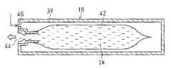
카트리지(18)는, 도 25에 상세하게 도시되어 있는 바와 같이, 경질 수지제의 밀봉 케이스로서의 케이스(39)의 내부에 가요재료에 의해 이뤄지는 잉크 팩(42)을 수용한 것이며, 케이스(39)의 일단에는, 외부로부터 가압 공기를 도입하는 공기 도입구(46)와, 공기 도입구(46)로부터 도입한 공기의 압력에서 잉크 팩(42)내에 수납한 잉크(Ik)를 외부로 도출하는 액체 도출구(44)가 마련되어 있다.As shown in detail in Fig. 25, the
그리고, 프린터(301)의 카트리지 홀더(17)에 카트리지(18)를 장착했을 때에, 서브 탱크(103) 및 가압 펌프(20)에 액체 도출구(44) 및 공기 도입구(46)가 각각 접속되도록 구성되어 있다.When the
그런데, 상술한 종래의 카트리지(18)는 프린터(301)의 카트리지 홀더(17)에 장전하는 것이며, 크기에 제약이 있기 때문에, 그다지 대용량의 것을 사용하는 것은 실제상 가능하지 않다. 즉, 카트리지는 스페이스적으로도 제약이 있는 프린터상의 카트리지 홀더에 장착되는 것이기 때문에, 그 카트리지에 수용 가능한 잉크 용량은 일반적으로 소량이다. 그 때문에, 비교적 대량의 인쇄를 하려고 할 경우에는, 카트리지의 빈번한 교환이 필요하게 되어 번거롭고, 또한 운전 자금도 많아지게 되었다. 특히, 소형화나 박형화가 도모된 프린터의 경우는, 카트리지 홀더를 위한 스페이스도 작아지고, 그 만큼 카트리지의 잉크 용량도 적어지기 때문에, 이러한 문제가 현저했다.By the way, the above-mentioned
그래서, 특히 대용량화가 필요할 경우에는, 옵션으로서 외부 부착의 외부 탱크를 설치하고, 그 외부 탱크로부터 잉크를 보급하는 것이 고려된다.Therefore, especially when a large capacity is required, it is considered to provide an external tank with an external attachment as an option and to replenish ink from the external tank.
그러나, 단순히 외부 부착의 외부 탱크로부터 잉크(Ik)를 보급하려고 해도, 프린터(301)내의 가압 펌프(20)에 의한 잉크(Ik)의 압송 시스템과의 정합성을 취할 수 없는 경우가 있고, 정확하게 동작하지 않을 우려가 있다.However, even when simply trying to replenish the ink Ik from the externally attached external tank, there is a case that the consistency with the feeding system of the ink Ik by the
또한, 최근에 예를 들면 특허문헌 5에 기재되는 것과 같이, 비교적 대량인 인쇄를 실행할 경우에는, 카트리지 홀더에 관한 장착 태양이 카트리지의 경우와 마찬가지인 어태치먼트를 카트리지 홀더에 장착하고, 이 어태치먼트를 거쳐서 대용량의 외부 잉크 탱크로부터 기록 헤드에 잉크를 공급 가능하게 하는 잉크 공급 시스 템이 제안되어 있다. 즉, 이 잉크 공급 시스템에서는, 내부에 공동 형상의 서브 탱크가 형성된 어태치먼트를 카트리지 홀더에 장착하도록 하고 있다. 그리고, 이 어태치먼트가 장착되었을 경우에는, 상기 어태치먼트에 부설된 펌프의 구동에 근거해 외부 탱크로부터 퍼 올릴 수 있는 잉크가 어태치먼트의 서브 탱크내에 소정 수위가 될 때까지 저류된 후, 그 저류 잉크가 어태치먼트의 하부에 형성된 액체 도출구로부터 기록 헤드의 액체 도입구로 도출되도록 되어 있다.In addition, as described in, for example, Patent Document 5, in the case of performing a relatively large amount of printing, an attachment similar to the case of the cartridge is attached to the cartridge holder in which the mounting mode for the cartridge holder is mounted, and through this attachment, a large capacity. An ink supply system has been proposed that enables ink to be supplied to a recording head from an external ink tank. That is, in this ink supply system, the attachment in which the cavity sub tank was formed inside is attached to a cartridge holder. And when this attachment is attached, the ink which can be pumped from an external tank based on the drive of the pump attached to the attachment is stored until it reaches a predetermined level in the sub tank of the attachment, and then the storage ink is attached to the attachment. The liquid outlet of the recording head is led out from the liquid outlet formed in the lower portion of the head.
그러나, 특허문헌 5의 어태치먼트의 경우에는, 카트리지 홀더에 관한 어태치먼트의 장착시에, 펌프를 구동시켜서 어태치먼트의 서브 탱크내를 부압으로 하고, 그 서브 탱크내에 외부 탱크로부터 잉크를 퍼 올려서 소정의 수위가 될 때까지 저류시킬 필요가 있고, 장착 완료까지 시간이 걸린다고 하는 문제가 있다. 추가로, 외부 탱크로부터 잉크를 퍼 올리기 위해서 펌프를 어태치먼트에 부설할 필요가 있고, 어태치먼트가 비용 높게 된다고 하는 문제가 있다. 따라서, 이 점에서, 특허문헌 5의 어태치먼트는 카트리지와 교환에 의해 카트리지 홀더에 장착할 경우에, 많이 손이 가는 동시에 비용이 높게 되기 때문에, 반드시 사용이 용이한 것은 아니었다.However, in the case of the attachment of patent document 5, at the time of attachment of the attachment to a cartridge holder, a pump is driven to make negative pressure in the sub tank of an attachment, and ink is pumped out of the external tank in the sub tank, and a predetermined level is changed. There is a problem in that it is necessary to store the product until it is completed, and it takes time to complete the installation. In addition, in order to pump ink out of the external tank, it is necessary to attach a pump to the attachment, and there is a problem that the attachment becomes expensive. Therefore, in this respect, when the attachment of patent document 5 is attached to a cartridge holder by exchange with a cartridge, it is not necessarily easy to use, since it takes a lot of hand and costs are high.
특허문헌 1 : 일본 특허 공개 제 2004-142405 호 공보Patent Document 1: Japanese Patent Application Laid-Open No. 2004-142405
특허문헌 2 : 일본 특허 공개 제 2001-212974 호 공보Patent Document 2: Japanese Patent Application Laid-Open No. 2001-212974
특허문헌 3 : 일본 특허 공개 제 2001-287380 호 공보Patent Document 3: Japanese Patent Laid-Open No. 2001-287380
특허문헌 4 : 일본 특허 공개 제 2003-311997 호 공보Patent Document 4: Japanese Patent Application Laid-Open No. 2003-311997
특허문헌 5 : 일본 특허 공개 제 2003-326732 호 공보Patent Document 5: Japanese Patent Application Laid-Open No. 2003-326732
본 발명의 목적은, 액체 분사 장치에 대하여 용이하고 또한 신속하게 장착 작업을 완료할 수 있는 저비용으로 사용이 용이한 어태치먼트 및 액체 공급 장치를 제공하는 것이다.It is an object of the present invention to provide an attachment and a liquid supply device that are easy to use at a low cost that can be completed easily and quickly for a liquid ejecting device.
또한, 본 발명의 목적은, 액체 분사 장치내의 공기 가압부에 의한 액체 압송 시스템과의 정합성을 취하면서, 안정한 액체의 보급을 하는 것이 가능한 액체 수납 용기 및 액체 공급 장치를 제공하는 것이다.It is also an object of the present invention to provide a liquid storage container and a liquid supply device capable of supplying a stable liquid while being matched with a liquid feeding system by an air pressurizing unit in the liquid ejecting device.
상기 목적을 달성하기 위해서, 본 발명은 액체 분사 장치에 장착 가능한 어태치먼트를 제공한다. 상기 액체 분사 장치의 장착부에는 액체 수용체가 분리 가능하게 장착된다. 상기 장착부는 상기 액체 수용체로부터 액체를 도입하기 위한 액체 도입부를 구비한다. 상기 어태치먼트에는 상기 액체 분사 장치의 외부로부터 액체 공급로를 통해서 액체가 공급된다. 상기 어태치먼트는 상기 장착부에 상기 액체 수용체와 교환 가능하게 장착 가능한 어태치먼트 본체와, 중계 유로를 구획하는 중계부를 구비한다. 상기 어태치먼트 본체가 상기 장착부에 장착되었을 경우에 상기 중계 유로의 하류단이 상기 액체 도입부에 위치 맞춤 상태에서 접속되도록, 상기 중계부는 상기 어태치먼트 본체에 배치된다. 상기 중계부에 있어서의 상기 중계 유로의 상류단에는 상기 액체 공급로의 하류단이 연결 가능하다.In order to achieve the above object, the present invention provides an attachment that can be mounted to a liquid ejecting apparatus. The liquid container is detachably mounted to the mounting portion of the liquid ejection apparatus. The mounting portion has a liquid introduction portion for introducing liquid from the liquid container. The attachment is supplied with liquid through the liquid supply passage from the outside of the liquid ejection apparatus. The attachment includes an attachment main body which is mountably replaceable with the liquid container in the mounting portion, and a relay that partitions the relay flow path. When the attachment main body is mounted on the mounting portion, the relay portion is disposed on the attachment main body such that the downstream end of the relay flow path is connected in alignment with the liquid introduction portion. A downstream end of the liquid supply passage can be connected to an upstream end of the relay flow path in the relay section.
또한, 본 발명은 액체 분사 장치의 장착부에 장착 가능한 액체 수납 용기를 제공한다. 상기 액체 분사 장치는 액체 분사부와 공기 가압부를 구비한다. 상기 액체 수납 용기는 외부로부터 가압 공기를 도입하기 위한 공기 도입구를 구비한다. 상기 액체 수납 용기가 상기 장착부에 장착되었을 경우에는, 상기 공기 도입구가 상기 공기 가압부에 접속된다. 액체 도출구는 상기 액체 수납 용기가 상기 장착부에 장착되었을 경우에 상기 액체 분사부에 접속된다. 상기 공기 도입구를 통해서 상기 액체 수납 용기에 공기가 도입되었을 경우에는, 상기 공기의 압력에 의해 상기 액체 수납 용기의 액체가 상기 액체 도입구를 통해서 상기 액체 분사부를 향해서 도출된다. 액체 보급구는 상기 액체 수납 용기에 상기 액체를 보급한다. 상기 액체 보급구에는 체크 밸브가 마련된다. 상기 체크 밸브는 상기 액체 보급구에 관한 외압이 내압보다 클 때에 개방하고, 내압이 외압보다 클 때에 폐쇄한다.The present invention also provides a liquid storage container that can be mounted to a mounting portion of a liquid ejecting apparatus. The liquid ejecting apparatus includes a liquid ejecting portion and an air pressurizing portion. The liquid container has an air inlet for introducing pressurized air from the outside. When the liquid container is attached to the mounting portion, the air inlet is connected to the air pressurizing portion. The liquid outlet port is connected to the liquid ejecting portion when the liquid storage container is mounted on the mounting portion. When air is introduced into the liquid storage container through the air inlet port, the liquid in the liquid storage container is led out through the liquid inlet toward the liquid ejection unit by the pressure of the air. The liquid supply port supplies the liquid to the liquid storage container. The liquid supply port is provided with a check valve. The check valve opens when the external pressure with respect to the liquid supply port is greater than the internal pressure, and closes when the internal pressure is greater than the external pressure.
또한, 본 발명은 액체 분사 장치에 액체를 공급하기 위한 액체 공급 장치를 제공한다. 상기 액체 분사 장치는 액체 분사부와 공기 가압부와 장착부를 구비한다. 상기 장착부에는 액체 카트리지가 장착 가능하다. 상기 액체 카트리지는 제 1 공기 도입구와 제 1 액체 도출구를 구비한다. 상기 액체 카트리지의 내부에 수납된 액체는, 상기 제 1 공기 도입구로부터 상기 액체 카트리지의 내부에 가압 공기가 도입되면 상기 가압 공기의 압력에 의해 상기 제 1 액체 도출구로부터 외부로 도출된다. 상기 액체 공급 장치는 상기 액체 카트리지의 대신에 상기 장착부에 장착 가능한 어태치먼트를 구비한다. 상기 어태치먼트는, 제 2 액체 도출구 및 제 2 공기 도입구를 구비한다. 상기 어태치먼트가 상기 장착부에 장착되었을 경우에는 상기 액체 분사부에 상기 제 2 액체 도출구가 접속되는 동시에, 상기 공기 가압부 에 상기 제 2 공기 도입구가 접속된다. 공급용 액체를 수용하는 외부 탱크는 관로에 의해 상기 제 2 액체 도출구에 접속된다. 상기 외부 탱크의 공급용 액체는 상기 관로를 통해서 상기 제 2 액체 도출구에 공급된다. 압력 조절부는 상기 공급용 액체의 공급압을 조절한다. 상기 압력 조절부는 상기 제 2 공기 도입구를 통해서 상기 공기 가압부에서 도입되는 공기압에 따라 상기 공급압을 조절한다.The present invention also provides a liquid supply device for supplying a liquid to the liquid ejecting device. The liquid ejecting apparatus includes a liquid ejecting portion, an air pressurizing portion and a mounting portion. A liquid cartridge can be mounted to the mounting portion. The liquid cartridge has a first air inlet and a first liquid outlet. The liquid contained in the liquid cartridge is drawn out from the first liquid outlet by the pressure of the pressurized air when pressurized air is introduced into the liquid cartridge from the first air inlet. The liquid supply apparatus has an attachment mountable to the mounting portion in place of the liquid cartridge. The attachment includes a second liquid outlet port and a second air inlet port. When the attachment is mounted on the mounting portion, the second liquid outlet port is connected to the liquid ejecting section, and the second air inlet port is connected to the air pressurizing section. The outer tank containing the supply liquid is connected to the second liquid outlet by a pipeline. The liquid for supply of the outer tank is supplied to the second liquid outlet through the conduit. The pressure regulator adjusts the supply pressure of the supply liquid. The pressure adjusting unit adjusts the supply pressure according to the air pressure introduced from the air pressurizing unit through the second air inlet.
본 발명에 따른 어태치먼트는 액체 분사 장치에 대하여 용이하고 또한 신속하게 장착 작업을 완료할 수 있고, 저비용으로 사용 편리성이 좋다.The attachment according to the present invention can easily and quickly complete the mounting work with respect to the liquid ejecting device, and it is easy to use at low cost.
이하, 본 발명을 구체화한 제 1 실시 형태를 도 1 내지 도 6에 따라서 설명한다.EMBODIMENT OF THE INVENTION Hereinafter, 1st Embodiment which actualized this invention is described according to FIGS.
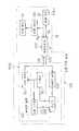
도 1 및 도 2에 도시하는 바와 같이, 본 실시 형태에 있어서의 액체 분사 장치로서의 잉크젯식 프린터(이하, "프린터"라고 한다)(10)는 대략 상자형의 본체 케이스(11)를 구비하고 있다. 본체 케이스(11)의 좌우 양측에는 한쌍의 프레임(12a, 12b)이 마주보도록 배설되고, 이들 양쪽 프레임(12a, 12b) 사이에는 막대 형상의 가이드 축(13)이 가설되어 있다. 가이드 축(13)에는 캐리지(14)가 이동 가능하게 삽통 지지되어 있고, 캐리지(14)는 프린터(10)가 구비하는 도시하지 않는 캐리지 모터의 구동력에 근거해 가이드 축(13)의 길이 방향에 따르는 방향(도 2에 도시하는 주 주사 방향(X))으로 왕복 이동하게 되어 있다.As shown in Fig. 1 and Fig. 2, an ink jet printer (hereinafter referred to as "printer") 10 as a liquid ejecting apparatus in the present embodiment is provided with a substantially box-shaped
캐리지(14)의 하면에는 액체 분사 헤드로서의 기록 헤드(15)가 마련되고, 이 기록 헤드(15)에는 액체로서의 잉크를 분사시키는 복수의 분사 노즐(도시 생략)이 형성되어 있다. 한편, 캐리지(14)의 상면에는 기록 헤드(15)에 대하여 압력 조정된 잉크를 공급하기 위한 밸브 유닛(16)이 마련되어 있다. 본 실시 형태에서는, 3개의 밸브 유닛(16)이 캐리지(14)상에 마련되어 있고, 각각 2색의 잉크를 압력 조정해서 6색의 잉크(블랙, 옐로우, 마젠타, 시안, 라이트 마젠타, 라이트 시안)를 기록 헤드(15)에 공급 가능하게 되어 있다.The lower surface of the
본체 케이스(11)의 좌우 양쪽 프레임(12a, 12b) 사이에 있어서 캐리지(14)가 이동하는 공간 영역보다도 하방이 되는 위치에는, 종이 피더부를 구성하는 플래튼(도시 생략)이 가이드 축(13)과 평행을 이루도록 배설되고, 이 플래튼에 의해 타겟으로서의 기록 용지(PA)가 주 주사 방향(X)과 직교하는 부 주사 방향(Y)(도 2 참조)으로 급송된다. 그리고, 이 부 주사 방향(Y)에 따라 급송되는 기록 용지(PA)상에 기록 헤드(15)가 분사 노즐로부터 잉크 방울을 토출함으로써, 본 실시 형태의 프린터(10)에서는 인쇄가 실시되게 되어 있다.The platen (not shown) constituting the paper feeder part is located at a position below the space area where the
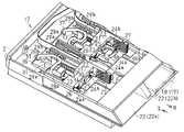
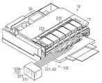
또한, 본체 케이스(11)의 좌우 양쪽 프레임(12a, 12b) 사이에 있어서 캐리지(14)가 이동하는 공간 영역의 상측에는 장착부로서의 카트리지 홀더(17)가 고정 설치(즉, 이동 불가능으로 고정 배치)되어 있다. 그리고, 이 카트리지 홀더(17)에 대하여, 도 4에 도시하는 액체 수용체로서의 카트리지(이하, "카트리지"라고 한다)(18)와 도 5에 도시하는 어태치먼트(19)가 교환 가능하게 장착되게 되어 있다. 또한, 도 1은 카트리지 홀더(17)에 대하여 6개의 어태치먼트(19)가 장착된 상태에 있는 프린터(10)룰 도시하고 있다.In addition, a
도 1에 도시하는 바와 같이, 본체 케이스(11)의 후부에는 가압 펌프(20)가 배설되어 있다. 그리고, 본체 케이스(11)내에는, 이 가압 펌프(20)의 배설 위치 부근을 경유하도록 해서 가요성 재료로 이루어지는 띠형의 수렴 유로(21)가 밸브 유닛(16)과 카트리지 홀더(17)와의 사이를 연결하도록 마련되어 있다(도 2 참조). 수렴 유로(21)는 액체 유로를 구성하는 6개의 잉크 유로와 기체 유로를 구성하는 1개의 공기 유로가 수렴된 것이며, 각 잉크 유로는 각각 대응하는 밸브 유닛(16)에 대하여 카트리지 홀더(17)에 장착된 카트리지(18)(또는 어태치먼트(19))로부터 잉크를 공급하게 되어 있다. 또한, 공기 유로는 가압 펌프(20)로부터 비산된 가압 공기를 카트리지 홀더(17)에 장착된 카트리지(18)(또는 어태치먼트(19))에 공급하게 되어 있다.As shown in FIG. 1, the pressurizing
도 3에 도시하는 바와 같이, 카트리지 홀더(17)는 상자형으로 형성된 홀더 케이스(17a)에 외주를 덮고 있고, 그 홀더 케이스(17a)내에 카트리지(18)(또는 어태치먼트(19))를 삽입 가능하게 하는 복수(본 실시 형태에서는 6개)의 소캣부(22)가 마련되어 있다. 또한, 도 3에는 2개의 소캣부(22)(카트리지(18) 등이 미장착 상태의 가까운 측의 소캣부(22a)와, 카트리지(18) 등이 장착 상태에 있는 먼 측의 소캣부(22b))가 도시되어 있다. 그리고, 이들의 소캣부(22)에 대하여, 카트리지(18)(또는 어태치먼트(19))는 카트리지 홀더(17)에의 장착시에는 도 3에 도시하는 화살표(L) 방향을 삽입 방향으로 해서 삽입하는 한편, 탈착시에는 동일하게 도 3에 도시하는 화살표(R) 방향을 빼냄 방향으로 해서 소캣부(22)로부터 방출되게 되어 있다.As shown in FIG. 3, the
소캣부(22)에는, 그 소캣부(22)의 대략 전체 횡폭에 상당하는 횡폭을 갖는 대략 직방체형의 슬라이더(23)가 배치되어 있다. 슬라이더(23)의 전면(도 3에 도시하는 화살표(R) 방향의 면)의 좌우 양단 근접 위치로부터는 한쌍의 위치 결정 돌기(24a, 24b)가 돌출 설치되는 동시에, 양쪽 위치 결정 돌기(24a, 24b) 사이에는 슬라이더(23)를 전후 방향에 관통하는 단면 직사각형 형상의 관통 구멍(25)이 형성되어 있다. 그리고, 이 관통 구멍(25)과 한쪽(도 3에서는 좌방)의 위치 결정 돌기(24a)와의 사이에는 슬라이더(23)를 전후 방향으로 관통하는 단면 원형 형상의 공기 도출구(26)가 형성되어 있다. 또한, 슬라이더(23)의 전면의 다른쪽 단부(도 3에서는 오른쪽 단부)로부터는 복수의 접점(도시 생략)을 갖는 단자부(27)가 전방으로 향해서 돌출 설치되어 있다.In the small-catch part 22, the slider 23 of the substantially rectangular parallelepiped shape which has the horizontal width corresponded to the substantially full width of the small-catch part 22 is arrange | positioned. A pair of
한편, 슬라이더(23)의 후면(도 3에 도시하는 화살표(L) 방향의 면)의 좌우 양단 근접 위치로부터는 한쌍의 레일(28a, 28b)이 후방으로 향해서 연장되도록 돌출 설치되어 있고, 이들 레일(28a, 28b)은 소캣부(22)의 저면에 고정 설치된 지지 가이드(29a, 29b)에 의해 전후 방향에의 접동 가능하게 지지되어 있다. 또한, 슬라이더(23)의 후면에 있어서, 관통 구멍(25)과 다른쪽(도 3에서는 오른쪽)의 레일(28b)과의 사이에서는 막대 형상을 이루는 샤프트(30)가 후방으로 향해서 연장되도록 돌출 설치되어 있다.On the other hand, a pair of
이 샤프트(30)에는 코일 스프링(31)이 느슨한 상태로 장착되어 있다. 코일스프링(31)은 일단(후단)이 소캣부(22)의 저면에 고정 설치된 걸림고정 돌기(32)에 고정되는 동시에 그 타단(전단)이 슬라이더(23)의 후면에 접촉되어 있다. 따라서, 슬라이더(23)는 코일 스프링(31)의 가압력에 의해 항상 빼냄 방향(도 3에 도시하는 화살표(R) 방향)으로 가압된 상태에서, 양 레일(28a, 28b)이 지지 가이드(29a, 29b)에 접동 가이드되는 것에 의해, 전후 방향으로의 왕복 이동 가능하게 되어 있다.The
도 3에 도시하는 바와 같이, 소캣부(22)의 좌우 방향 대략 중앙에서 슬라이더(23)의 왕복 이동 범위보다도 후방이 되는 위치에는 지지대(33)가 마련되어 있다. 지지대(33)의 전면으로부터는, 프린터(10)에 있어서의 액체 도입부로서의 잉크 공급 니들(34)이 전방으로 향해서 연장되도록 돌출 설치되어 있다. 잉크 공급 니들(34)은, 내부에 액체 유로(도시 생략)가 형성된 파이프로 이뤄지고, 그 전단부 외주면에는 잉크 공급 니들(34)내에 잉크를 도입하기 위한 도입 구멍(34a)이 개구 형성되어 있다. 그리고, 잉크 공급 니들(34)은, 도 3에 도시하는 먼 측의 소캣부(22b)에 놓을 수 있도록, 슬라이더(23)가 코일 스프링(31)의 가압력에 저항해서 후퇴했을 경우에는 슬라이더(23)의 관통 구멍(25)을 후방으로부터 전방으로 관통하고, 도입 구멍(34a)이 형성된 전단부를 슬라이더(23)의 전면보다도 전방으로 돌출시키도록 되어 있다.As shown in FIG. 3, the support base 33 is provided in the position which becomes back from the reciprocation movement range of the slider 23 in the substantially center of the left-right direction of the socket part 22. As shown in FIG. From the front side of the support stand 33, the ink supply needle 34 as a liquid introduction part in the
한편, 지지대(33)의 후면으로부터는 연결관(35)이 후방으로 향해서 연장하여 설치되어 있다. 이 연결관(35)은 잉크 공급 니들(34)과 연통해서 액체 유로를 구성하는 것이며, 그 후단(즉, 하류단)이 홀더 케이스(17a)의 대략 전체 횡폭에 걸치도록 배설된 연결 유로(36)에 접속되어 있다. 연결 유로(36)는 각 소캣부(22)의 액체 유로를 구성하는 6개의 잉크 유로(도시 생략)와 기체 유로를 구성하는 1개의 공기 유로(도시 생략)가 수렴된 것이며, 각 잉크 유로는 전술한 수렴 유로(21)에 형성된 각각이 대응하는 잉크 유로에 접속되어 있다.On the other hand, the connecting
또한, 연결 유로(36)에 있어서의 공기 유로에서는 가요성을 갖는 가압 공기 공급 튜브(37)가 연장 설치되고, 그 선단이 슬라이더(23)의 공기 도출구(26)에 후방으로부터 연결되어 있다. 즉, 가압 펌프(20)로부터 가압 공기가 배출되었을 경우에는, 그 가압 공기가 수렴 유로(21) 및 연결 유로(36)의 공기 유로를 통해서 가압 공기 공급 튜브(37)내에 도입된 후, 슬라이더(23)의 공기 도출구(26)로부터 전방으로 도출되도록 되어 있다.Moreover, in the air flow path in the
또한, 소캣부(22)의 저면에는 고정부를 구성하는 계합 레버(38)가 슬라이더(23)의 하방을 전후 방향으로 연장되도록 마련되고 있고, 이 계합 레버(38)의 전단에는 돌기(38a)가 돌출 설치되어 있다. 즉, 이 계합 레버(38)는 소캣부(22)에 카트리지(18)(또는 어태치먼트(19))가 수용(장착)되어서 슬라이더(23)가 후퇴했을 경우에, 돌기(38a)를 돌출 설치한 전단이 슬라이더(23)의 전면보다도 전방에 위치하는 배치 구성으로 되어 있다. 그리고, 그 경우에는, 계합 레버(38)의 전단에 돌출 설치된 돌기(38a)가 카트리지(18)에 형성된 결합부(47)(도 4의 (a) 참조) 또는 어태치먼트(19)에 형성된 결합부(56)(도 5 참조)에 계합되고, 카트리지(18) 등을 소캣부(22)에 있어서 이동 불가능하게 걸림고정 유지하게 되어 있다.Moreover, the engagement lever 38 which comprises the fixed part is provided in the bottom face of the socket part 22 so that the lower side of the slider 23 may extend in the front-back direction, and the
다음에, 카트리지 홀더(17)의 각 소캣부(22)에 대하여 교환 가능하게 장착되는 카트리지(18) 및 어태치먼트(19)에 대해서 설명한다. 우선, 도 4를 참조하면서 카트리지(18)에 대해서 설명한 후, 도 5를 참조하면서 어태치먼트(19)에 대해서 설 명한다.Next, the
도 4의 (a) 및 (b)에 도시하는 바와 같이, 카트리지(18)는 합성 수지재로 상자체 형상으로 형성된 케이스(39)를 구비하고 있고, 케이스(39)의 내부에는 환상을 이루는 구획 벽(40)에 의해 일정 용적의 수용실(제 1 공기 도입실)(41)이 형성되어 있다. 그리고, 이 수용실(41)내에 가요성을 갖는 봉지체로 되고, 내부에 잉크가 봉입된 잉크 팩(42)을 수용하고 있다. 잉크 팩(42)의 일단(도 4의 (b)에서는 좌단)에는 내부에 봉입되어 있는 잉크를 외부로 도출하기 위한 잉크 도출 부재(43)가 액체 도출부로서 마련되어 있다. 또한, 도시하지 않지만, 잉크 도출 부재(43)의 내부에는 체크 밸브 기능을 갖는 밸브 기구(도시 생략)가 마련되어 있다. 또한, 케이스(39)는 상방이 개구된 바닥이 있는 상자체 형상을 이루는 것이며, 그 개구 부분이 커버 부재(도시 생략)에 의해 폐쇄된 것이다.As shown in Figs. 4A and 4B, the
이 케이스(39)의 전면(소캣부(22)에의 수용(장착)시에 수용 방향의 전방이 되는 면)(39a)의 대략 중앙부에는 지지구로서 기능하는 제 1 액체 도출구(44)가 관통 형성되어 있다. 이 제 1 액체 도출구(44)는 소캣부(22)의 슬라이더(23)에 관통 형성된 관통 구멍(25)과 대응하는 것이며, 카트리지(18)가 소캣부(22)에 수용(장착)되었을 경우에는, 그 관통 구멍(25)과 위치 맞춤 상태가 되는 것이다. 그리고, 이 제 1 액체 도출구(44)에 대하여 케이스(39)내에 수용된 잉크 팩(42)의 잉크 도출 부재(43)가 삽입 지지되어 있다. 따라서, 카트리지(18)가 소캣부(22)에 수용(장착)되었을 경우에는, 케이스(39)의 제 1 액체 도출구(44)가 슬라이더(23)의 관통 구멍(25)과 위치 맞춤되는 것에 의해, 그 관통 구멍(25)으로부터 전방으로 돌출 한 잉크 공급 니들(34)의 전단이 잉크 팩(42)의 잉크 도출 부재(43)에 대하여 위치 맞춤 상태가 되어서 접속되게 되어 있다.A first
또한, 케이스(39)의 전면(39a)의 좌우 양단 근접 위치에는 한쌍의 위치 결정 오목부(45a, 45b)가 형성되어 있다. 이들 각 위치 결정 오목부(45a, 45b)는 소캣부(22)의 슬라이더(23)로부터 돌출 설치된 각 위치 결정 돌기(24a, 24b)와 대응하는 것이며, 카트리지(18)가 소캣부(22)에 수용(장착)되었을 경우에는, 대응하는 위치 결정 돌기(24a, 24b)와 위치 맞춤 상태가 되는 것이다. 그리고, 그 위치 맞춤 상태에 있어서는, 대응하는 위치 결정 돌기(24a, 24b)가 위치 결정 오목부(45a, 45b)내에 끼워맞춰지는 것에 의해, 카트리지(18)를 수용 방향과 교차하는 방향에의 이동 규제를 도모해서 위치 결정하게 되어 있다.In addition, a pair of
또한, 케이스(39)의 전면(39a)에 있어서, 제 1 액체 도출구(44)와 한쪽(도 4의 (a)에서는 하방)의 위치 결정 오목부(45a)와의 사이에는 잉크 팩(42)을 수용한 수용실(41)내에 연통하는 제 1 공기 도입구(46)가 관통 형성되어 있다. 이 제 1 공기 도입구(46)는 소캣부(22)의 슬라이더(23)에 관통 형성된 공기 도출구(26)와 대응하는 것이며, 카트리지(18)가 소캣부(22)에 수용(장착)되었을 경우에는, 그 공기 도출구(26)와 위치 맞춤 상태가 되는 것이다. 그리고, 그 위치 맞춤 상태에 있어서는, 가압 펌프(20)로부터 가압 공기 공급 튜브(37) 등을 거쳐서 공급되는 가압 공기가 공기 도출구(26)와 제 1 공기 도입구(46)를 거쳐서 수용실(41)내에 도입되고, 그 가압력에 의해 잉크 팩(42)이 압착되는 것 같이 변형하는 결과, 잉크 팩(42)내의 잉크가 잉크 도출 부재(43)로부터 도출되게 되어 있다.Moreover, in the
또한, 케이스(39)의 전면(39a)에 있어서의 다른쪽(도 4의 (a)에서는 상방)단 근접 위치에는, 카트리지 홀더(17)의 소캣부(22)에 마련된 계합 레버(38)와 계합 관계를 갖는 결합부(47)가 케이스(39)의 저면(도 4의 (a)에서는 좌방)에 따르도록 함몰 형성되어 있다. 또한, 케이스(39)의 다른쪽(도 4의 (a)에서는 상방)의 측면에 있어서의 전면(39a) 근접 위치에는 소캣부(22)의 슬라이더(23)로부터 돌출 설치된 단자부(27)와 접속 관계를 갖는 회로 기판(48)이 부착되어 있다. 그리고, 이들의 결합부(47) 및 회로 기판(48)은 카트리지(18)가 소캣부(22)에 수용(장착)되었을 경우에, 각각 소캣부(22)의 계합 레버(38) 및 단자부(27)와 계합 및 접속되게 되어 있다.In addition, the engagement lever 38 provided in the socket part 22 of the
다음에, 어태치먼트(19)에 대해서 설명한다.Next, the
도 5에 도시하는 바와 같이, 어태치먼트(19)는 바닥이 있는 상자체 형상을 이루는 어태치먼트 본체(49)와, 어태치먼트 본체(49)의 상방 개구 부분을 폐쇄 가능한 커버 부재(50)를 구비하고 있다. 이 어태치먼트 본체(49)와 커버 부재(50)에는 서로 대응하는 복수 개소에 걸림고정 오목부(51)와 걸림고정 갈고리(52)가 각각 형성되어 있고, 걸림고정 오목부(51)와 걸림고정 갈고리(52)가 탄성적으로 걸림고정됨으로써, 커버 부재(50)는 어태치먼트 본체(49)에 걸림고정 유지되게 되어 있다.As shown in FIG. 5, the
어태치먼트 본체(49)는 도 4의 (a) 및 (b)에 도시하는 카트리지(18)의 케이스(39)와 대략 동일한 형태를 하고 있다. 즉, 어태치먼트 본체(49)의 내부에는 카트리지(18)의 케이스(39)의 내부에 형성된 구획 벽(40)과 동일의 환상을 이루는 구 획 벽(53)이 형성되어 있다. 또한, 어태치먼트 본체(49)의 전면(49a)에는 카트리지(18)의 케이스(39)에 형성된 제 1 액체 도출구(44) 및 한쌍의 위치 결정 오목부(45a, 45b)와 동일 형태의 제 2 액체 도출구(54) 및 한쌍의 위치 결정 오목부(55a, 55b)가 카트리지(18)의 케이스(39)의 전면(39a)에 있어서의 제 1 액체 도출구(44) 및 각 위치 결정 오목부(45a, 45b)와 같은 위치에 형성되어 있다. 또한, 어태치먼트 본체(49)에는 카트리지(18)의 케이스(39)에 형성된 결합부(47) 및 회로 기판(48)과 각각 동일 형태를 이루는 결합부(56) 및 회로 기판(57)이 카트리지(18)의 케이스(39)에 있어서의 결합부(47) 및 회로 기판(48)과 동일 위치에 각각 형성되어 있다.The
한편, 어태치먼트 본체(49)의 전면(49a)에 있어서, 카트리지(18)의 케이스(39)의 전면(39a)에 형성된 제 1 공기 도입구(46)와 대응하는 위치에는, 원형스탠드 형상을 이루는 폐쇄부(58)가 형성되어 있고, 이 점에서 어태치먼트 본체(49)는 카트리지(18)의 케이스(39)와 구성상의 상위가 있다. 또한, 어태치먼트 본체(49)의 경우는, 그 주벽(49b)과 구획 벽(53)의 일부(후벽측이 되는 부분)에 튜브 지지부로서의 절결부(59)가 형성되어 있고, 이 점에서도 카트리지(18)의 케이스(39)와 구성상의 상위가 있다.On the other hand, in the
또한, 카트리지(18)의 케이스(39)의 경우는, 그 수용실(41)내에 잉크 팩(42)을 수납하는 구성이었지만, 어태치먼트 본체(49)의 경우에는, 그 내부에 중계부 및 액체 도출 부재로서 기능하는 잉크 도출 부재(60)가 착탈 가능하게 장착되어 있다. 이 잉크 도출 부재(60)는 그 내측이 잉크의 통과를 허용하는 유로 구조, 즉 중계 유로(61)로 되어 있다. 그리고, 그 중계 유로(61)의 상류단이 되는 잉크 도출 부재(60)의 기단(60a)에는 가요성을 갖는 잉크 공급 튜브(액체 공급로)로서의 잉크 튜브(62)의 선단(하류단)(62a)이 연결되어 있다.In the case of the
또한, 어태치먼트 본체(49)에 있어서의 구획 벽(53)의 내측에서 어태치먼트 본체(49)의 전면(49a)에 형성된 지지구로서의 제 2 액체 도출구(54)의 근방 위치에는 한쌍의 리브(63a, 63b) 및 지지 스탠드(64)로 이루어지는 지지부(65)가 형성되어 있다. 그리고, 잉크 도출 부재(60)는 중계 유로(61)의 하류단이 되는 선단(60b)을 제 2 액체 도출구(54)에 삽통 지지시키는 동시에, 지지부(65)에 의해 위치 결정된 상태에서 어태치먼트 본체(49)에 장착되어 있다. 또한, 그 경우 잉크 튜브(62)는 그 선단(하류단)(62a)보다도 기단(상류측)의 일부가 어태치먼트 본체(49)의 주벽(49b) 및 구획 벽(53)에 형성된 절결부(59)에 의해 지지된다.Moreover, a pair of
또한, 잉크 도출 부재(60)의 선단(60b)에 있어서 중계 유로(61)내에는 코일 스프링(66), 중계 유로(61)를 차단하는 스토퍼(67), 및 스토퍼 시트(도시 생략)가 형성된 원환상의 패킹(68)이 조립되어 있다. 즉, 코일 스프링(66)이 스토퍼(67)를 패킹(68)에 가압하는 것에 의해, 중계 유로(61)는 스토퍼(67)에 의해 항상은 차단되게 되어 있다. 그리고, 어태치먼트 본체(49)가 카트리지 홀더(17)의 소캣부(22)에 수용(장착)되고, 잉크 공급 니들(34)의 전단이 제 2 액체 도출구(54)에 삽입된 상태로 되어서 스토퍼(67)를 코일 스프링(66)의 가압력에 저항해서 중계 유로(61)내로 밀어 넣은 경우에, 중계 유로(61)는 스토퍼(67)에 의한 차단 상태가 해소되어서 잉크를 도출하게 되어 있다.In the
상술 바와 같이 구성된 어태치먼트(19)는 어태치먼트 본체(49)가 카트리지(18)의 케이스(39)와 동일 형태를 이루고 있다. 그리고, 이 어태치먼트 본체(49)에 있어서는, 제 2 액체 도출구(54), 위치 결정 오목부(55a, 55b), 결합부(56), 및 회로 기판(57)이 카트리지(18)의 케이스(39)에 있어서의 제 1 액체 도출구(44), 위치 결정 오목부(45a, 45b), 결합부(47), 및 회로 기판(48)과 동일 위치에 마련되어 있다. 그 때문에, 어태치먼트(19)는 카트리지 홀더(17)의 소캣부(22)에 대하여 카트리지(18)와 교환 가능하게 동일한 장착 형태로 장착되게 된다.In the
다음에, 본 실시 형태에 있어서의 잉크 공급 시스템에 대해서 설명한다.Next, the ink supply system in this embodiment is demonstrated.
도 6에 도시하는 바와 같이, 본 실시 형태의 프린터(10)는 다단 구성의 래크(69)상에 탑재된 상태에서 사용된다. 이 래크(69)는 하단 탑재부(69a), 중단 탑재부(69b) 및 상단 탑재부(69c)를 구비하고, 프린터(10)는 중단 탑재부(69b)상에 탑재되어 있다. 또한, 하단 탑재부(69a)상에는 외부 폐액 회수체로서의 폐액 탱크(70)가 탑재되어 있다. 그리고, 이 폐액 탱크(70)와 프린터(10)와의 사이가 폐액 유로를 구성하는 폐액 튜브(71)에 연결되어 있다. 또한, 폐액 튜브(71)의 상류단은 프린터(10)내에 마련된 폐액 회수 용기(도시 생략)에 연결되어 있다. 따라서, 프린터(10)로부터 배출된 폐잉크(폐액)는 폐액 튜브(71)를 거쳐서 하방에 위치하는 대용량의 폐액 탱크(70)에 회수되게 된다.As shown in FIG. 6, the
한편, 래크(69)의 상단 탑재부(69c)상에는 카트리지(18)내의 잉크 팩(42)보다도 대용량의 잉크를 저류하는 외부 수용체로서의 외부 탱크(72)가 탑재되어 있 다. 그리고, 이 외부 탱크(72)에 있어서 잉크가 저류된 수용실(72a)내에 어태치먼트(19)의 잉크 도출 부재(60)에 하류단이 연결된 잉크 튜브(62)의 상류단이 수용되어 있다. 그 결과, 어태치먼트(19)에 대하여는 외부 탱크(72)의 수용실(72a)내에 저류되어 있는 잉크가 잉크 튜브(62)를 거쳐서 수두차에 의해 공급된다.On the other hand, on the upper mounting
즉, 외부 탱크(72)를 어태치먼트(19)보다도 높은 위치에 설치하고, 외부 탱크(72)내에 있어서의 잉크(Ik)의 액면과 어태치먼트(19)내에 있어서의 잉크(Ik)의 액면과의 사이에 고저차를 마련하고 있다. 어태치먼트(19)의 액체 보급구(125)에 접속된 보급용의 잉크 튜브(62)의 선단은 외부 탱크(72)의 상단에 부착한 커버(133)를 관통시켜서 외부 탱크(72)의 바닥부에 수용되어 있다. 커버(133)에는 잉크(Ik)의 액면에 대기압이 작용하도록 공기 구멍(133a)이 개공되어 있다.That is, the
본 실시 형태에서는, 어태치먼트(19), 외부 탱크(72) 및 잉크 튜브(62)에 의해, 프린터(10)에 잉크(액체)를 공급하는 잉크 공급 장치로서의 액체 공급 장치(73)가 구성되어 있다.In this embodiment, the
여기에서 다음에, 상술한 바와 같이 구성된 프린터(10)에 있어서의 어태치먼트(19)와 액체 공급 장치(73)의 작용에 대해서 설명한다.Here, the operation of the
그런데, 카트리지 홀더(17)에 카트리지(18)가 장착되어 있을 경우에 있어서 대량으로 인쇄를 하려고 할 때는, 카트리지(18)가 카트리지 홀더(17)로부터 분리된다. 그리고, 그 교환으로서 어태치먼트(19)가 카트리지 홀더(17)에 장착된다. 이 교환 장착에 있어서, 소캣부(22)의 슬라이더(23)는, 도 3에 도시하는 좌측 앞의 소캣부(22a)에 있어서의 위치(미장착시 위치)로부터 도 3의 우측 뒤의 소캣부(22b)에 있어서의 위치(장착시 위치)로, 어태치먼트(19)에 가압되어 이동한다. 그리고, 이 경우에 있어서, 소캣부(22)에 수용(장착)된 어태치먼트(19)는 어태치먼트 본체(49)의 전면(49a)에 형성된 제 2 액체 도출구(54) 등이 소캣부(22)의 슬라이더(23)에 형성된 관통 구멍(25) 등과 위치 맞춤 상태가 된다.By the way, when the
즉, 슬라이더(23)의 위치 결정 돌기(24a, 24b)가 어태치먼트 본체(49)의 위치 결정 오목부(55a, 55b)에 위치 맞춤 상태가 되어서 끼워맞춰지는 동시에, 소캣부(22)의 계합 레버(38)가 어태치먼트 본체(49)의 결합부(56)에 계합하고, 어태치먼트(19)를 이동 불가능하게 걸림고정 유지한다. 또한, 슬라이더(23)의 단자부(27)가 어태치먼트 본체(49)의 회로 기판(57)에 접속되고, 어태치먼트(19)와 프린터(10)의 제어부(도시 생략)와의 사이에서의 잉크 소비량과 기타의 정보 전달이 행하여지게 된다. 또한, 어태치먼트 본체(49)의 폐쇄부(58)가 슬라이더(23)의 공기 도출구(26)에 위치 맞춤 상태가 되고, 그 공기 도출구(26)를 폐쇄한다.That is, the
또한, 소캣부(22)상의 잉크 공급 니들(34)의 전단이 어태치먼트 본체(49)의 제 2 액체 도출구(54)(및 잉크 도출 부재(60)의 선단(60b))내에 위치 맞춤 상태가 되어서 삽입되고, 중계 유로(61)를 폐쇄하는 스토퍼(67)가 코일 스프링(66)의 가압력에 저항해서 중계 유로(61)의 보다 내부로 가압 이동한다. 그렇게 하면, 이 스토퍼(67)에 의한 중계 유로(61)의 폐쇄 상태가 해소되어, 외부 탱크(72)로부터 잉크 튜브(62)를 거쳐서 수두차에 의해 어태치먼트(19)의 잉크 도출 부재(60)까지 도달한 잉크는 중계 유로(61)내를 그대로 통과해서 잉크 공급 니들(34)의 도입 구멍(34a)내로 신속하게 유입한다. 그리고, 그 잉크는 잉크 공급 니들(34)로부터, 연결관(35), 연결 유로(36) 및 수렴 유로(21)의 잉크 유로를 경유하고, 기록 헤드(15)의 밸브 유닛(16)에 공급된다.In addition, the front end of the ink supply needle 34 on the socket portion 22 is positioned in the second liquid outlet port 54 (and the
상기 제 1 실시 형태에 의하면, 이하와 같은 효과를 얻을 수 있다.According to the said 1st Embodiment, the following effects can be acquired.
(1) 카트리지 홀더(17)의 소캣부(22)에 어태치먼트(19)를 장착했을 경우에는, 소캣부(22)에 마련된 관통 구멍(25)(잉크 공급 니들(34))에 대하여 어태치먼트 본체(49)의 제 2 액체 도출구(54)(잉크 도출 부재(60))가 위치 맞춤 상태가 되고, 그 장착시에 잉크를 공급 가능한 연결 상태가 된다. 즉, 소캣부(22)에 대하여 어태치먼트 본체(49)를 수용(장착)한다고 하는 단일 작업만으로, 외부 탱크(72)로부터 프린터(10)의 기록 헤드(15)에 관한 잉크 공급 상태를 형성할 수 있다. 따라서, 프린터(10)에 대하여는 용이하고 또한 신속하게 저비용으로 어태치먼트(19)의 장착 작업을 완료할 수 있고, 매우 사용이 편리한 것이 된다.(1) When the
(2) 중계 유로(61)가 형성된 잉크 도출 부재(60)는 어태치먼트 본체(49)에 착탈이 가능하기 때문에, 중계 유로(61)내에 막힘이 발생했을 경우나, 스토퍼(67)의 움직임이 불량할 경우 등에는, 그 잉크 도출 부재(60)를 어태치먼트 본체(49)로부터 분리해서 불량의 유지보수를 하는 것이 가능하고, 보다 한층 사용이 편리한 것이 된다.(2) Since the
(3) 어태치먼트(19)가 장착되는 카트리지 홀더(17)는 인쇄시에 왕복 이동하는 캐리지(14) 위에서가 아니라, 본체 케이스(11)상에 있어서 이동 불가능하게 고정 배치되어 있다. 그 때문에, 외부 탱크(72)로부터 연장되는 잉크 튜브(62)가 캐리지(14)의 왕복 이동에 따라 인장되거나 하는 일이 없다. 따라서, 외부 탱크(72) 로부터 어태치먼트(19)로의 잉크 튜브(62)를 통한 원활한 잉크 공급 상태를 확보할 수 있다.(3) The
(4) 잉크 튜브(62)는 가요성을 갖고 있기 때문에, 설치 상태가 불안정이 되기 쉽지만, 잉크 도출 부재(60)에 연결된 선단(하류단)(62a)보다도 상류측의 부분이 어태치먼트 본체(49)의 절결부(59)에 의해 양호하게 지지된다. 그 때문에, 불안정한 설치 상태가 될 일도 없고, 이 잉크 튜브(62)와 접속된 어태치먼트(19)를 보다 더 사용이 편리하게 된다.(4) Since the
(5) 액체 공급 장치(73)에 있어서는, 외부 탱크(72)가 래크(69)의 상단 탑재부(69c)상에 탑재되는 동시에, 어태치먼트(19)가 장착된 프린터(10)가 래크(69)의 중단 탑재부(69b)상에 탑재되어 있기 때문에, 외부 탱크(72)로부터 잉크 튜브(62)를 거쳐서 어태치먼트(19)로 수두차에 의해 잉크를 강제적으로 공급할 수 있다. 따라서, 프린터(10)에 있어서 기록 헤드(15)에 관한 잉크 공급 부족이 생기는 우려를 회피할 수 있다.(5) In the
(6) 래크(69)의 중단 탑재부(69b)상에 프린터(10)가 탑재되고, 중단 탑재부(69b)보다도 하방의 하단 탑재부(69a)상에 폐액 탱크(70)가 탑재되고, 이 폐액 탱크(70)와 프린터(10)와의 사이가 폐액 튜브(71)에 의해 연결되어 있다. 그 때문에, 프린터(10)로부터 배출된 폐잉크(폐액)를 수두차의 이용에 의해 양호하게 폐액 탱크(70)로 회수할 수 있다.(6) The
(7) 어태치먼트(19)가 카트리지 홀더(17)의 소캣부(22)에 수용(장착)되었을 경우에는, 어태치먼트 본체(49)의 전면(49a)에 마련된 폐쇄부(58)가 소캣부(22)의 슬라이더(23)에 마련된 공기 도출구(26)를 폐쇄한다. 그 때문에, 프린터(10)에서 가압 펌프(20)로부터 배출한 가압 공기의 공기량이 일정량 이상이 되었을 경우를 가압 에러(예컨대, 공기 누설)이라고 하는 검출 기구를 마련하고 있을 경우에 있어서, 카트리지(18)와 어태치먼트(19)와의 교환 장착을 행한 것에 의해 본의 아니게 에러 검출되는 경우를 미연에 방지할 수 있다.(7) When the
다음에, 본 발명의 제 2 실시 형태에 대해서 도 7을 참조해서 설명한다.Next, a second embodiment of the present invention will be described with reference to FIG.
이 제 2 실시 형태에 있어서의 어태치먼트(74)는 제 1 실시 형태에 있어서의 어태치먼트(19)와 대비한 경우, 제 1 실시 형태의 어태치먼트(19)에 있어서의 폐쇄부(58) 대신에 제 2 공기 도입구(75) 및 공기 도입실(76)을 구비한 점에서만 구성이 상위하고, 그 밖의 구성은 제 1 실시 형태의 어태치먼트(19)와 동일하다. 그 때문에, 이하에서는 제 2 실시 형태에 있어서 제 1 실시 형태와의 공통 부분(부재)에는 제 1 실시 형태와 동일한 부호를 부여하여 중복 설명을 생략하고, 주로 제 1 실시 형태와의 상위 부분을 설명한다.The
도 7의 (a) 및 (b)에 도시하는 바와 같이, 제 2 실시 형태의 어태치먼트(74)는 어태치먼트 본체(49)의 전면(49a)에 제 2 공기 도입구(75)가 관통 형성되어 있다. 그리고, 이 제 2 공기 도입구(75)와 위치적으로 대응하도록, 어태치먼트 본체(49)의 내부에는 공기 도입실(76)이 구획 형성되어 있다. 이 공기 도입실(76)은 카트리지(18)의 케이스(39)내에 형성된 공기 도입실로서의 수용실(41)보다도 소용적으로 형성되어 있다.As shown to (a) and (b) of FIG. 7, in the
그 때문에, 이 제 2 실시 형태에서는, 카트리지 홀더(17)의 소캣부(22)에 어 태치먼트(74)가 수용(장착)되었을 경우, 어태치먼트 본체(49)의 전면(49a)의 제 2 공기 도입구(75)가 소캣부(22)의 슬라이더(23)의 공기 도출구(26)와 위치 맞춤 상태가 되어 접속된다. 그리고, 가압 펌프(20)로부터 배출된 가압 공기가 공기 도출구(26)로부터 제 2 공기 도입구(75)를 거쳐서 공기 도입실(76)내에 도입되게 된다.Therefore, in this 2nd Embodiment, when the
따라서, 이 제 2 실시 형태에서는 제 1 실시 형태에 있어서의 상기 (1) 내지 (6)의 효과 이외에 다음과 같은 효과를 얻을 수 있다.Therefore, in this 2nd Embodiment, the following effects can be acquired in addition to the effect of said (1)-(6) in 1st Embodiment.
(8) 어태치먼트(74)가 카트리지 홀더(17)의 소캣부(22)에 수용(장착)되었을 경우에 있어서, 슬라이더(23)의 공기 도출구(26)로부터 어태치먼트 본체(49)의 제 2 공기 도입구(75)를 거쳐서 공기 도입실(76)내에 도입되는 가압 공기의 허용 공기량이 매우 작게 설정된다. 그 때문에, 프린터(10)에서 가압 펌프(20)로부터 배출한 가압 공기의 공기량이 일정량(예를 들면, 카트리지(18)의 수용실(41)의 용적량) 이상이 되었을 경우를 가압 에러(예를 들면, 공기 누출)로 하는 검출 기구를 마련하고 있을 경우라도, 어태치먼트(19)와의 장착에 따라 본의 아니게 에러 검출되는 경우를 미연에 방지할 수 있다. 이 점은 제 1 실시 형태에 있어서의 상기 (7)의 효과와 거의 동일하다.(8) When the
(9) 이 제 2 실시 형태의 경우는, 또한 프린터(10)에서 가압 펌프(20)로부터 배출한 가압 공기의 공기량이 일정량(예를 들면, 어태치먼트(74)의 공기 도입실(76)의 용적량)에 도달하지 않을 경우를 가압 에러(예를 들면, 공기 경로 폐쇄 등에 의한 가압 불량)라고 하는 제어 시스템을 구비하고 있을 경우에, 그러한 가압 에러도 양호하게 검출할 수 있도록 된다는 특유의 효과가 있다.(9) In the case of this second embodiment, the amount of air of the pressurized air discharged from the
다음에, 제 3 실시 형태에 대해서 도 8을 참조해서 설명한다.Next, a third embodiment will be described with reference to FIG. 8.
도 8에 도시하는 바와 같이, 이 제 3 실시 형태에 있어서의 어태치먼트(77)는 제 1 실시 형태에 있어서의 어태치먼트(19)를 카트리지 홀더(17)의 소캣부(22)의 병설수와 동일한 수(본 실시 형태에서는 6개)만 병렬 상태로 해서 일체화시킨 형태를 하는 대형의 것이다. 즉, 이 어태치먼트(77)는 제 1 실시 형태에 있어서의 어태치먼트(19)의 어태치먼트 본체(49)와 커버 부재(50)를 각각 6개씩 병설했을 경우에 대응하는 형태의 어태치먼트 본체(78)와 커버 부재(79)를 갖고 있다.As shown in FIG. 8, the
그리고, 도시는 하지 않지만, 그 어태치먼트 본체(78)내에는 제 1 실시 형태에 있어서의 잉크 도출 부재(60)와 동일한 잉크 도출 부재(60)가 일정한 배치 간격을 두고 6개 착탈 가능하게 마련되어 있다. 각 잉크 도출 부재(60)는 어태치먼트(77)가 카트리지 홀더(17)에 장착되었을 경우에, 6개 소캣부(22)의 각각에 마련된 각 잉크 공급 니들(34)과 위치 맞춤 상태가 되도록 배설되어 있다. 그리고, 어태치먼트(77)내에서 각 잉크 도출 부재(60)의 기단(60a)에 선단(62a)을 연결시킨 각 잉크 튜브(62)가 어태치먼트 본체(78)의 절결부(59)로부터 외부로 인출되어, 외부 탱크(72)(도 6 참조)와 접속되어 있다.Although not shown in the drawing, six attachments and detachments of the same ink lead-
따라서, 이 제 3 실시 형태에서는 제 1 실시 형태에 있어서의 상기 (1) 내지 (6)의 효과에 추가해서, 다음과 같은 효과를 얻을 수 있다.Therefore, in this 3rd Embodiment, in addition to the said (1)-(6) effect in 1st Embodiment, the following effects can be acquired.
(10) 카트리지 홀더(17)로부터 복수(6개)의 카트리지(18)를 분리한 후에 어태치먼트(77)를 교환 장착할 경우에 있어서, 각 카트리지(18)의 절하에는 복수회(6회)의 탈착 작업을 필요로 한 것에 대해서, 어태치먼트(77)는 1회의 장착 작업에 의해 각 소캣부(22)의 잉크 공급 니들(34)에 잉크 도출 부재(60)를 동시에 접속할 수 있다. 즉, 이 경우의 어태치먼트(77)는 6색분의 카트리지(18)에 대응한 원터치 장착형의 다색 대응형 어태치먼트(77)로 된다. 따라서, 보다 한층, 신속하게 어태치먼트(77)의 장착 작업을 완료할 수 있다.(10) When the
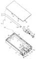
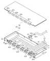
다음에 제 4 실시 형태에 대해서 도 9 내지 도 11을 참조해서 설명한다.Next, a fourth embodiment will be described with reference to FIGS. 9 to 11.
도 9 및 도 10에 도시하는 바와 같이, 이 제 4 실시 형태에 있어서의 어태치먼트(80)는 횡방향으로 길다랗고 바닥이 있는 상자형상의 어태치먼트 본체(81)와, 이 어태치먼트 본체(81)의 상방 개구 부분을 폐쇄 가능한 커버 부재(82)를 구비하고 있다. 도 10에 도시하는 바와 같이, 어태치먼트 본체(81)의 전면(81a)에는 가로 방향으로 일정 간격을 두고 복수(본 실시 형태에서는 6개)의 하측 지지부(83a)가 형성되는 동시에, 커버 부재(82)의 전단연(82a)에는 어태치먼트 본체(81)의 하측 지지부(83a)와 대응하도록 복수(6개)의 상측 지지부(83b)가 형성되어 있다. 각 하측 지지부(83a) 및 상측 지지부(83b)는 각각 반원형상의 입구연을 대향하도록 갖고 있고, 어태치먼트 본체(81)에 커버 부재(82)를 장착한 경우에 서로 합쳐지고, 가로 방향으로 일정 간격을 두고 병렬 상태로 복수(6개)의 지지구(83)를 형성하게 되어 있다(도 9 참조).As shown in FIG. 9 and FIG. 10, the
어태치먼트 본체(81)에 있어서의 각 하측 지지부(83a)의 이면측에는 칼라형상 홈으로 이루어지는 지지부(84)가 각각 형성되고 있어, 각 지지부(84)에 대하여 제 1 실시 형태의 어태치먼트(19)의 경우와 마찬가지로 잉크 도출 부재(중계부)(60)가 착탈 가능하게 지지되어 있다. 그리고, 각 잉크 도출 부재(60)에 있어서 의 중계 유로(61)의 상류단이 되는 잉크 도출 부재(60)의 기단(60a)에는 외부 탱크(72)(도 6 참조)로부터 연장되는 액체 공급로로서의 잉크 튜브(62)의 선단(하류단)(62a)이 연결되어 있다.The
또한, 어태치먼트 본체(81)의 전면(81a)에 있어서의 좌우 양 단부에는 한쌍의 위치 결정 오목부(85a, 85b)가 형성되어 있다. 또한, 어태치먼트 본체(81)의 전면(81a)에 있어서 일단(도 9에서는 우단)의 위치 결정 오목부(85a)의 좌측에는 폐잉크(폐액)의 도입을 가능하게 하는 폐잉크 도입구(제 2 폐액 도입부)(86)가 형성되어 있다. 폐잉크 도입구(86)의 이면측에는 칼라형상의 지지 홈(87)이 형성되어 있고, 이 지지 홈(87)에 대하여 잉크 도출 부재(60)와 동일 형태의 폐잉크 도입 부재(88)가 착탈 가능하게 지지되어 있다. 그리고, 이 폐잉크 도입 부재(88)에 폐액 탱크(70)(도 6 참조)로부터 연장되는 폐액 튜브(71)가 연결되어 있다.Moreover, a pair of positioning recessed
한편, 어태치먼트 본체(81)의 전면(81a)에 있어서 타단(도 9에서는 좌단)의 위치 결정 오목부(85b)의 좌측은 평면형상의 제 2 접촉부(89)로 되고, 이 제 2 접촉부(89)의 하측에는 어태치먼트 본체(81)의 전면(81a)으로부터 회로 기판 수납부(90)가 오목하게 형성되어 있다. 그리고, 이 회로 기판 수납부(90)내에 도시하지 않는 회로 기판이 설치되어 있다. 이렇게, 제 4 실시 형태의 어태치먼트(80)는 제 3 실시 형태의 어태치먼트(77)의 경우와 마찬가지로, 다색 대응형 어태치먼트(80)이며, 카트리지 홀더(17)에 대하여는, 이 어태치먼트(80)와 동일 형태를 이뤄서 내부에 6색분의 잉크 팩을 내장한 다색 대응형 카트리지(도시 생략)와 교환 가능하게 장착된다. 또한, 이 카트리지는 그 전면에 제 1 폐액 도입부(폐잉크 도 입구)가 형성된 폐액 회수 기능을 갖는 것이며, 또한 전면에는 후술하는 밸브 개폐 레버(99)에 접촉해서 동일 개폐 레버(99)를 가압이동하는 제 1 접촉부(도시 생략)가 형성되어 있다.On the other hand, the left side of the positioning
여기에서, 다음에 상기 어태치먼트(80)가 다색 대응형으로 또한 폐액 회수 기능을 갖추어서 이뤄지는 카트리지와 교환 가능하게 장착되는 카트리지 홀더(17)에 대해서 도 11 및 도 12를 참조하여 설명한다.Here, with reference to Figs. 11 and 12, the
도 11에 도시하는 바와 같이, 제 4 실시 형태에 있어서의 카트리지 홀더(17)에는, 어태치먼트(80)(및 카트리지)와 마찬가지로 횡방향으로 길다랗고 대략 직방체형상의 접속부(91)가 마련되어 있다. 이 접속부(91)에 있어서, 어태치먼트(80)가 카트리지 홀더(17)에 장착될 때에, 어태치먼트 본체(81)의 전면(81a)과 대향하게 되는 전면(91a)에는 어태치먼트(80)의 각 위치 결정 오목부(85a, 85b)와 대응하는 위치에 한쌍의 위치 결정 돌기(92a, 92b)가 돌출 설치되는 동시에, 어태치먼트(80)의 회로 기판 수납부(90)와 대응하는 위치로부터는 단자부(93)가 돌출 설치되어 있다.As shown in FIG. 11, the
따라서, 어태치먼트(80)가 접속부(91)에 장착되었을 경우에는, 각 위치 결정 돌기(92a, 92b)가 대응하는 위치 결정 오목부(85a, 85b)에 끼워맞춰지고, 어태치먼트(80)의 장착 방향(도 11에서는 좌우 방향)과 교차하는 방향에의 이동을 규제한다. 또한, 단자부(93)가 회로 기판 수납부(90)에 설치된 회로 기판에 접촉하고, 어태치먼트(80)와 프린터(10)의 제어부(도시 생략)와의 사이에서의 잉크 소비량 등의 정보 전달이 행하여지게 된다. 그리고, 도시하지 않지만, 어태치먼트(80)에 마 련된 결합부와 접속부(91)에 마련된 계합 레버가 계합함으로써, 어태치먼트(80)는 카트리지 홀더(17)의 접속부(91)에 대하여 이동 불가능하게 장착된다.Therefore, when the
또한, 접속부(91)의 전면(91a)에 있어서, 어태치먼트(80)의 폐잉크 도입구(86)와 대응하는 위치에는 폐잉크 도출 니들(폐액 도출부)(94)이 돌출 설치되는 동시에, 각 지지구(83)와 대응하는 위치에는 잉크 공급 니들(액체 도입부)(95)이 돌출 설치되어 있다. 또한, 각 잉크 공급 니들(95)의 선단에는 도시하지 않는 도입 구멍이 개구 형성되어 있다. 그리고, 각 잉크 공급 니들(95)의 기단은 접속부(91)의 내부에 각 잉크 공급 니들(95)마다 개별 대응하도록 형성된 잉크 유로(액체 유로)(96)에 연통되어 있다.Moreover, in the
따라서, 어태치먼트(80)가 접속부(91)에 장착되었을 경우에는, 폐잉크 도출 니들(94)이 폐잉크 도입구(86)에 삽입 상태가 되고, 프린터(10)로부터 배출된 폐잉크가 폐잉크 도입 부재(88)로부터 폐액 튜브(71)를 경유해서 폐액 탱크(70)(도 6 참조)에 회수된다. 또한, 외부 탱크(72)로부터 잉크 튜브(62)를 거쳐서 공급되는 잉크가 잉크 도출 부재(60)의 중계 유로(61)를 거쳐서 대응하는 잉크 공급 니들(95)로부터 접속부(91)내의 잉크 유로(96)에 유입한다.Therefore, when the
여기서, 잉크 유로(96)에 유입한 잉크는 접속부(91)내에 마련된 유로 밸브(97)를 경유해서, 접속부(91)의 전면(91a)으로부터 돌출하는 연통부(98)로부터 프린터(10)의 기록 헤드(15)에 공급된다. 그리고, 이 경우, 유로 밸브(97)는 잉크의 역류를 방지하는 등의 목적을 위하여, 접속부(91)에 어태치먼트(80)(또는 카트리지)가 미장착의 경우에는, 폐쇄 밸브 상태로 되어서 잉크 유로(96)를 폐쇄한 상 태로 되도록 되어 있다. 그 때문에, 도 11에 도시하는 바와 같이, 접속부(91)에 있어서 어태치먼트(80)의 제 2 접속부(89)와 대응하는 위치에는, 어태치먼트(80)의 장착에 따라 잉크 유로(96)를 개방 상태로 하도록 동작하는 밸브 개폐 레버(가동 부재)(99)가 마련되어 있다.Here, the ink flowing into the
이 밸브 개폐 레버(99)는 작동편(99a)과, 종동편(99b)과, 회동축(99c)을 구비하고 있다. 회동축(99c)은 작동편(99a) 및 종동편(99b)을 서로 연결 고정한 상태에서 양쪽 작동편(99a) 및 종동편(99b)의 회동 중심이 된다. 작동편(99a)은 판형상체이며, 그 전단의 한쪽 코너로부터는 돌기(99d)가 돌출 설치되어 있다. 그리고, 작동편(99a)(및 종동편(99b))은 도시하지 않은 가압 스프링의 가압력에 의해, 항상 도 11에 도시하는 화살표 방향(반시계 방향)으로 가압되고, 작동편(99a)의 전단연이 어태치먼트(80)의 장착 방향에 대하여 약간 기운 상태로 유지되게 되어 있다.This valve opening / closing
이 상태에 있어서, 어태치먼트(80)를 카트리지 홀더(17)의 접속부(91)에 장착하면, 그 장착 동작에 의해 어태치먼트(80)의 제 2 접촉부(89)가 밸브 개폐 레버(99)에 있어서의 작동편(99a)의 돌기(99d)에 접촉하고, 작동편(99a)이 회동축(99c)을 중심으로 해서 시계 방향으로 회동한다. 그러면, 이 작동편(99a)의 회동에 추종해서 종동편(99b)도 시계 방향으로 회동한다. 그 결과, 종동편(99b)의 회동에 근거해 유로 밸브(97)가 폐쇄 밸브 상태로부터 개방 밸브 상태로 이동되어, 프린터(10)의 기록 헤드(15)와 잉크 공급 니들(95)과의 사이가 잉크 유로(96)를 거쳐서 연통되어, 잉크의 공급이 가능한 상태가 된다.In this state, when the
따라서, 이 제 4 실시 형태에서는, 제 1 실시 형태에 있어서의 상기 (1) 내지 (6)과 거의 동일한 효과에 추가해서 다음과 같은 효과를 얻을 수 있다.Therefore, in this 4th Embodiment, the following effects can be acquired in addition to the effect substantially the same as said (1)-(6) in 1st Embodiment.
(11) 카트리지 홀더(17)의 접속부(91)에 어태치먼트(80)를 장착하면, 어태치먼트(80)의 제 2 접촉부(89)가 접속부(91)의 밸브 개폐 레버(99)를 유로 밸브(97)가 밸브 개방되는 방향으로 추동하기 때문에, 어태치먼트(80)의 장착에 따라 잉크 공급 니들(95)과 기록 헤드(15)와의 사이에서 잉크 유로(96)를 적절하게 연통시키게 할 수 있다. 따라서, 유로 밸브(97)를 구비한 카트리지 홀더(17)에 대하여 어태치먼트(80)와 카트리지와의 교환 장착을 할 경우에, 잉크의 역류 등을 억제하면서, 프린터(10)의 설계 변경을 필요없게 해서 범용성이 높은 어태치먼트 기능을 향수할 수 있다.(11) When the
(12) 또한, 폐액 회수 기능을 갖는 카트리지와의 교환 장착에 경우에도, 어태치먼트(80)가 구비하는 폐잉크 도입구(86) 및 폐잉크 도입 부재(88)를 경유해서 폐액 탱크(70)까지 폐액 튜브(71)에서 양호하게 폐잉크 회수를 도모할 수 있다.(12) In addition, even in the case of exchange mounting with a cartridge having a waste liquid collection function, the
또한, 상기 각 실시 형태는 이하와 같은 별도의 실시 형태(다른 예)로 변경해도 좋다.In addition, you may change each said embodiment to another embodiment (other example) as follows.
· 도 13에 도시하는 바와 같이, 외부 탱크(72)의 수용실(72a)중 잉크 액면에서도 상방 공간 영역을 공기 도입실로서, 그 공간 영역에 외부로부터 가압 펌프로서의 공기 펌프(134)의 구동에 근거해 가압 공기 공급 튜브로서의 공기 공급 튜브(135)를 거쳐서 가압 공기를 보내주도록 해도 좋다. 즉, 외부 탱크(72)의 상단에 장착한 커버(133)의 공기 구멍(133a)에 공기 공급 튜브(135)를 거쳐서 공기 펌 프(134)를 접속하고, 외부 탱크(72) 내부의 잉크(Ik)의 액면에 대기압 대신에 공기 펌프(134)에서 생성한 공기압을 수용한다.As shown in Fig. 13, the upper space region is also used as the air introduction chamber in the ink liquid level in the
이와 같이 구성하면, 그 가압 공기의 가압력에 의해 잉크 튜브(62)를 거쳐서 외부 탱크(72)로부터 어태치먼트(19)(74, 77, 80)로 잉크를 강제적으로 공급할 수 있게 되고, 프린터(10)의 기록 헤드(15)에 있어서 잉크 공급 부족이 생기는 것을 억제할 수 있다.With this configuration, ink can be forcibly supplied from the
또한, 외부 탱크(72)와 어태치먼트(19)와의 사이에 특별한 고저차를 마련할 필요가 없다. 또한, 공기 펌프(134)를 제어하는 것으로, 잉크 공급압의 단속이나 조절이 간단하게 될 수 있다.In addition, there is no need to provide a special height difference between the
· 이러한 잉크의 강제 공급에 근거하는 구성의 변경예로서는, 도 14에 도시하는 바와 같이, 외부 탱크(72)의 수용실(공기 도입실)(72a)내에 대용량의 잉크 팩(130)을 수용하고, 그 수용실(72a)내에 가압 펌프로서의 공기 펌프(134)로부터 공기 공급 튜브(135)를 거쳐서 가압 공기를 보내주도록 해도 좋다. 즉, 경질재료에 의해 이뤄진 밀폐 케이스로서의 외부 탱크(72)의 내부에 공기 펌프(134)에서 생성한 공기압을 도입함으로써, 잉크 팩(130)내의 잉크(Ik)를 어태치먼트(19)를 향해서 추출하도록 구성하고 있다.As an example of the configuration change based on the forced supply of ink, as shown in FIG. 14, a large-
이와 같이 구성했을 경우는, 잉크 팩(130)내의 잉크(Ik)를 가압하는 공기압에 의해, 어태치먼트(19)를 향한 잉크(Ik)의 공급압을 확보할 수 있다.When comprised in this way, the supply pressure of the ink Ik toward the
따라서, 외부 탱크(72)와 어태치먼트(19)와의 사이에 특별한 고저차를 마련할 필요가 없다. 또한, 공기 펌프(134)를 제어하는 것에 의해, 잉크 공급압의 단 속이나 조절이 간단하게 될 수 있다.Therefore, there is no need to provide a special height difference between the
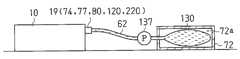
또한, 도 15에 도시하는 바와 같이, 외부 탱크(72)의 수용실(72a)내에 대용량의 잉크 팩(130)을 수용하고, 그 잉크 팩(130)과 어태치먼트(19)(74, 77, 80)와의 사이를 연결하는 잉크 튜브(62)의 도중에 흡인 펌프로서의 액체 펌프(137)를 배치하는 구성으로서도 좋다. 즉, 외부 탱크(72)를 개방형의 케이스로 하고, 외부 탱크(72) 내부의 잉크 팩(130)의 잉크(Ik)를 액체 펌프(137)에 의해 어태치먼트(19)로 압송해서 보급압을 확보하도록 해도 좋다.As shown in FIG. 15, a large-
이 경우는, 액체 펌프(137)의 구동에 따라, 상류측의 잉크 팩(130)내로부터 잉크가 흡인되는 동시에, 그 흡인된 잉크가 하류측의 어태치먼트(19)(74, 77, 80)로 강제적으로 공급된다. 따라서, 액체 펌프(137)를 제어하는 것에 의해, 잉크 공급압의 단속이나 조절이 간단하게 될 수 있다.In this case, ink is sucked from the
· 제 1 내지 제 3 실시 형태의 각 어태치먼트(19, 74, 77)의 어태치먼트 본체(49, 78)에 폐잉크 도입구(폐액 도입구)를 형성하는 동시에, 폐잉크 도입 부재를 장착하고, 그 폐잉크 도입 부재에 폐액 튜브(폐액 유로)를 접속해서 폐액 탱크에 폐잉크를 회수시키도록 해도 좋다.A waste ink introduction port (waste liquid introduction port) is formed in the
· 제 4 실시 형태에 있어서, 어태치먼트(80)의 제 2 접촉부(89)에 추동되는 것에 의해 잉크 유로(액체 유로)(96)를 개폐하는 가동 부재는 밸브 개폐 레버(99)이외의 부재 구성, 예를 들면 제 2 접촉부(89)에 추동되어서 직선적으로 이동함으로써 유로 밸브(97)를 개폐시키는 부재 구성으로 해도 좋다.In the fourth embodiment, the movable member which opens and closes the ink flow path (liquid flow path) 96 by being driven by the
· 제 2 실시 형태에 있어서, 어태치먼트 본체(49)에 마련되는 공기 도입 실(76)의 용적은 카트리지(18)의 수용실(41)보다도 작은 용적이 되는 것이면, 그 용적은 적절하게 변경 가능하다.In 2nd Embodiment, if the volume of the
· 각 어태치먼트 본체(49, 78, 81)에 있어서 튜브 지지부는 절결부(59) 이외의 튜브 지지용의 리브나 홈 등을 더 형성하도록 해도 좋다.In each attachment
· 카트리지 홀더(17)는 프린터(10)에 있어서의 캐리지(14)상에 마련된 것이라도 좋다.The
· 중계부 및 액체 도출 부재로서의 잉크 도출 부재(60)는 내부에 중계 유로(61)가 형성되는 통체 형상을 하는 것이면, 예를 들면 단순한 파이프체이라도 좋다.The ink lead-
· 중계부는 어태치먼트 본체(49, 78, 81)에 일체 형성된 것이라도 좋다.The relay portion may be formed integrally with the
이하, 첨부 도면에 근거해서 본 발명의 제 5 실시 형태에 따른 액체 수납 용기 및 액체 공급 장치를 상세하게 설명한다.EMBODIMENT OF THE INVENTION Hereinafter, based on an accompanying drawing, the liquid storage container and liquid supply apparatus which concern on 5th Embodiment of this invention are demonstrated in detail.
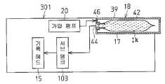
도 16에 도시하는 바와 같이, 잉크젯 기록 장치로서의 프린터(10)의 내부에는 액체 분사부로서의 기록 헤드(15), 서브 탱크(103), 공기 가압부로서의 가압 펌프(20), 카트리지 홀더(17)를 구비하고 있다. 카트리지 홀더(17)에는 본 실시 형태에 따른 액체 수납 용기로서의 복수의 어태치먼트(120)가 장전되어 있다.As shown in Fig. 16, inside the
각 어태치먼트(120)는 도 25에 도시한 종래의 카트리지(18)와 동일한 외형을 갖고, 도 17에 도시하는 바와 같이, 경질 수지제의 밀봉 케이스(121)의 내부에 가요성 재료에 의해 이뤄진 잉크 팩(122)을 수용한 것이며, 밀봉 케이스(121)의 일단에는 외부로부터 가압 공기를 도입하는 제 2 공기 도입구(75)와, 제 2 공기 도입 구(75)로부터 도입한 공기의 압력에 의해 잉크 팩(122)내에 수납한 잉크(액체)(Ik)를 외부로 도출하는 제 2 액체 도출구(54)가 마련되어 있다.Each
그리고, 프린터(10)의 카트리지 홀더(17)에 어태치먼트(120)를 장착했을 때에, 서브 탱크(103) 및 가압 펌프(20)에 제 2 액체 도출구(54) 및 제 2 공기 도입구(75)가 각각 접속되도록 구성되어 있다.When the
또한, 이 어태치먼트(120)에는, 종래의 카트리지(18)와 상이한 구성으로서, 밀봉 케이스(121)의 타단에 외부로부터 잉크(Ik)를 보급하기 위한 액체 보급구(125)가 마련되는 동시에, 이 액체 보급구(125)에는 외압이 내압보다 클 때 개방하고 또한 내압이 외압보다 클 때 폐쇄되는 체크 밸브(126)가 마련되어 있다.In addition, the
도 16에 도시한 것과 같이, 각 어태치먼트(120)의 액체 보급구(125)에는 잉크 튜브(62)를 거쳐서, 외부 부착에 의해 외부 탱크(72)가 접속되어 있다. 이 결과, 어태치먼트(120), 잉크 튜브(62) 및 외부 탱크(72)에 의해, 액체 공급 장치(73)가 구성되어 있다.As shown in FIG. 16, the
여기에서, 외부 탱크(72)내의 잉크(보급용 액체)(Ik)를 액체 보급구(125)에 보급하기 위한 보급압으로 해서, 대기압보다 높은 압력에서 또한 가압 펌프(20)의 공기압(가압 공기의 도입에 의해 어태치먼트(120)내의 잉크(Ik)를 제 2 액체 도출구(54)로부터 도출시킬 때의 도출압)보다도 낮은 압력을 가하도록 구성되어 있다.Here, the supply pressure for supplying the ink (supplement liquid) Ik in the
다음에, 상술한 본 실시 형태의 어태치먼트(120) 및 액체 공급 장치(73)의 작용을 설명한다.Next, the operation of the
본 실시 형태의 어태치먼트(120)의 구성에 의하면, 어태치먼트(120)의 액체 보급구(125)에는 체크 밸브(126)가 조립되어 있다. 제 2 공기 도입구(75)로부터의 가압 공기의 도입에 의해 어태치먼트(120)내의 잉크(Ik)를 제 2 액체 도출구(54)로부터 도출시킬 때의 도출압보다도, 액체 보급구(125)로부터 외부 탱크(72)내의 잉크(Ik)를 보급할 때의 보급압을 작게 설정해 둔다. 이에 의해, 액체 공급 장치(73)의 외부 탱크(72)로부터 어태치먼트(120)에 잉크(Ik)를 한창 보급되고 있는 때에, 가압 펌프(20)로부터 가압 공기가 어태치먼트(120)내에 도입된 때에는 체크 밸브(126)가 폐쇄된다.According to the structure of the
그리고, 가압 펌프(20)에 의한 가압 공기의 도입을 정지하면, 외부 탱크(72)로부터의 보급압(외압)이 어태치먼트(120)의 내압에 능가하므로, 체크 밸브(126)가 개방되어 잉크(Ik)의 보급이 행하여진다.When the introduction of pressurized air by the
이와 같이, 공기압을 이용한 기록 헤드(15)에의 잉크(Ik)의 도출에 영향을 주지 않고, 어태치먼트(120)내에 잉크(Ik)의 보급을 실행할 수 있으므로, 종래의 카트리지(18)와 교환해서 어태치먼트(120)를 사용했을 경우에도, 프린터(10)의 잉크의 압송 시스템에 있어서의 가압 펌프(20)와의 완전한 정합성을 확보할 수 있고, 정상 동작을 보증할 수 있다.In this way, the supply of the ink Ik can be performed in the
또한, 카트리지(18)를 본 발명의 어태치먼트(120)로 교환하는 것 만으로, 프린터(10)에는 아무것도 개조를 실시할 필요가 없으므로, 대용량의 외부 탱크(72)로부터 잉크(Ik)를 보급하는 보급 시스템을 간단한 옵션으로서 부가할 수 있다. 또한, 어태치먼트(120)에 관한 잉크(Ik)의 보충은 프린터(10)의 가압 펌프(20)의 압력보다도 낮게 설정하면 좋으므로, 액체 공급 장치(73)의 간략화를 도모할 수도 있 다.In addition, since only the
따라서, 프린터(10)는 아무것도 개조하지 않고, 상기 프린터(10)내의 잉크(Ik)의 압송 시스템에 있어서의 가압 펌프(20)와의 정합성을 취하면서, 안정한 잉크(Ik)의 보급을 할 수 있는 어태치먼트(120) 및 액체 공급 장치(73)를 제공할 수 있다.Therefore, the
또한, 상기 실시 형태의 어태치먼트(120)에서는, 도 17에 도시하는 바와 같이, 밀봉 케이스(121)의 내부에 수용한 잉크 팩(122)에 잉크(Ik)를 수납하고, 잉크 팩(122)의 외부에 잉크 도출을 위한 가압 공기를 도입하도록 구성했지만, 도 18에 도시하는 어태치먼트(120A)와 같이, 밀봉 케이스(121)의 내부에 직접 잉크(Ik)를 수납하고, 밀봉 케이스(121)내에 수납한 공기 팩(122A)에 가압 공기를 도입하는 것에서도, 마찬가지로 잉크(Ik)를 가압 펌프(20)의 도입 공기압에 따른 압력으로 도출할 수 있다.In addition, in the
다음에, 본 실시 형태에 있어서의 액체 공급 장치(73)의 외부 탱크(72)로부터 어태치먼트(120(120A))를 향해서 잉크(Ik)를 보급할 경우의 보급압을 가하는 방법에 있어서 설명한다. 보급압의 가하는 방법으로서는, 도 6, 도 13 내지 도 15에 열거한 것과 같은 각종의 방법을 채용할 수 있다.Next, a description will be given of a method of applying a supply pressure in the case of supplying ink Ik from the
도 6에 도시한 구성에서는, 외부 탱크(72)내와 어태치먼트(120)내에 있어서의 각 잉크(Ik)의 액면차에 따른 위치 수두가 어태치먼트(120(120A))의 액체 보급구(125)에 보급압으로서 추가된다. 보급압은 외부 탱크(72)내의 잉크(Ik)의 액면의 높이를 변경하는 것에 의해 용이하게 조절할 수 있다.In the structure shown in FIG. 6, the position head according to the liquid level difference of each ink Ik in the
도 13과 같이 구성했을 경우는, 외부 탱크(72)내의 잉크(Ik)를 가압하는 공기압에 의해 어태치먼트(120(120A))를 향해서 잉크(Ik)를 보급할 경우의 보급압을 확보할 수 있다.13, the supply pressure at the time of supplying ink Ik toward attachment 120 (120A) by the air pressure which pressurizes the ink Ik in the
도 14에 도시하는 바와 같이 구성했을 경우는, 잉크 팩(130)내의 잉크(Ik)를 가압하는 공기압에 의해, 어태치먼트(120(120A))를 향해서 잉크(Ik)를 보급할 경우의 보급압을 확보할 수 있다. 따라서, 공기 펌프(134)를 제어하는 것에 의해, 보급압의 단속이나 조절이 간단하게 될 수 있다.14, the supply pressure at the time of supplying ink Ik toward attachment 120 (120A) by the air pressure which pressurizes the ink Ik in the
도 15에 도시한 경우는, 액체 펌프(137)에서 잉크(Ik)를 압송할 경우는, 액체 펌프(137)를 제어하는 것에 의해, 보급압의 단속이나 조절이 간단하게 될 수 있다.In the case shown in FIG. 15, when the ink Ik is pumped by the
또한, 본 발명의 액체 수납 용기 및 액체 공급 장치에 따른 공기 도입구, 액체 도출구, 액체 보급구, 체크 밸브 및 외부 탱크 등의 구성은 상기 실시 형태의 구성에 한정되는 것은 아니고, 본 발명의 취지에 근거해서 다양한 형태를 채용할 수 있는 것은 말할 필요도 없다.Incidentally, the configuration of the air inlet port, the liquid outlet port, the liquid supply port, the check valve, the external tank, etc. according to the liquid storage container and the liquid supply device of the present invention is not limited to the configuration of the above-described embodiment, and is intended for the purpose of the present invention. Needless to say, it is possible to adopt various forms based on.
이하, 첨부 도면에 근거해서 본 발명의 제 6 실시 형태에 따른 액체 공급 장치를 상세하게 설명한다.EMBODIMENT OF THE INVENTION Hereinafter, based on an accompanying drawing, the liquid supply apparatus which concerns on 6th Embodiment of this invention is demonstrated in detail.
도 19에 도시하는 바와 같이, 본 발명의 일 실시 형태에 따른 액체 공급 장치(100)가 조립된 프린터(10)의 내부에는 기록 헤드(15), 서브 탱크(103), 가압 펌프(20), 카트리지 홀더(17)를 구비하고 있다. 도 20에 도시하는 바와 같이, 카트리지 홀더(17)에는 통상의 액체 카트리지 대신에 어태치먼트(220)가 장전되어 있 다.As shown in FIG. 19, the
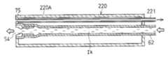
각 어태치먼트(220)는 도 25에 도시한 종래의 카트리지(18)와 동일한 외형을 갖고, 도 21에 도시하는 바와 같이, 경질 수지제의 중공 케이스(220A)의 일단에 잉크(Ik)를 중공 케이스(220A) 외부에 도출하는 제 1 접속구로서의 제 2 액체 도출구(54)와, 외부로부터 가압 공기를 도입하는 제 2 접속구로서의 제 2 공기 도입구(75)가 마련되어 있다.Each
그리고, 프린터(10)의 카트리지 홀더(17)에 어태치먼트(220)를 장착했을 때에, 프린터(10)의 서브 탱크(103) 및 가압 펌프(20)에 어태치먼트(220)의 제 2 액체 도출구(54) 및 제 2 공기 도입구(75)가 각각 접속되도록 구성되어 있다.When the
도 21에 도시하는 바와 같이, 각 어태치먼트(220)의 제 2 공기 도입구(75) 및 제 2 액체 도출구(54)에는 중공 케이스(220A)의 내측으로부터 공기 검출 튜브(221)의 선단과, 관로로서의 잉크 튜브(62)의 선단이 각각 접속되어 있다. 이들의 공기 검출 튜브(221) 및 잉크 튜브(62)는 중공 케이스(220A)의 반대측으로부터 중공 케이스(220A) 외부로 인출되어, 도 20에 도시하는 액체 공급 장치 본체(100A)에 접속되어 있다.As shown in FIG. 21, the
액체 공급 장치(100)는 이 액체 공급 장치 본체(100A)와 공기 검출 튜브(221), 잉크 튜브(62) 및 어태치먼트(220)에 의해 구성되어 있다.The
도 19에 도시하는 바와 같이, 액체 공급 장치 본체(100A)는 외부 탱크(72)와, 압력 검출기(223)와, 압력 조절부(225)를 구비하고 있다. 외부 탱크(72)는 내부에 잉크(공급용 액체)(Ik)를 수용하고, 어태치먼트(220)의 제 2 액체 도출구(54) 에 잉크 튜브(62)를 거쳐서 접속된다. 압력 검출기(223)는 어태치먼트(220)의 제 2 공기 도입구(75) 및 공기 검출 튜브(221)를 통해서 프린터(10)의 가압 펌프(20)에 의해 도입되는 공기압을 검출한다. 압력 조절부(225)는 압력 검출기(223)의 검출 압력에 따라, 외부 탱크(72)로부터 어태치먼트(220)의 제 2 액체 도출구(54)에 공급하는 잉크(Ik)의 공급압을 조절한다.As shown in FIG. 19, the liquid supply apparatus
압력 조절부(225)에는 외부 탱크(72)내의 잉크(Ik)를 가압 펌프(20)의 공급압 이상으로 가압할 수 있는 가압부(226)와, 그 가압력을 필요에 따라서 해제하는 것에 의해 공급압을 조정하는 릴리스 밸브(227)와, 압력 검출기(223)의 검출 신호에 근거해서 이들 가압부(226)나 릴리스 밸브(227)를 제어하는 것에 의해, 잉크(Ik)의 공급압을 압력 검출기(223)의 검출압과 동일하게 설정하는 CPU(제어부)(240)가 포함되어 있다.The
본 실시 형태에 있어서의 제 2 공기 도입구(75)로부터 압력 검출기(223)까지의 공기 검출 튜브(221)내의 부분의 용적은 공기압을 검출하기 위한 공간의 용적이며, 이 용적은 통상의 카트리지(18)(도 25 참조)에 있어서의 가압 공기 도입용의 공간의 용적과 거의 동등하게 설정되어 있다.The volume of the part in the
다음에, 본 실시 형태에 따른 액체 공급 장치(100)의 작용을 설명한다.Next, the operation of the
상술한 바와 같이, 통상의 카트리지(18)(도 25 참조) 대신에 본 실시 형태의 액체 공급 장치(100)를 프린터(10)의 카트리지 홀더(17)에 장착하면, 프린터(10)에 설정된 공기 압력에 따른 공급압에 의해, 압력 조절부(225)는 잉크(Ik)를 기록 헤드(15)에 공급한다. 따라서, 프린터(10)의 가압 펌프(20)에 의한 잉크 압송 시스 템(액체 압송 시스템)과, 액체 공급 장치(100)에 의한 잉크 압송 시스템 사이의 정합성을 확보할 수 있고, 프린터(10)의 정상 동작을 보증할 수 있다.As described above, when the
즉, 카트리지(18)에 의한 잉크 압송 시스템과 액체 공급 장치(100)에 의한 잉크 압송 시스템과의 사이의 정합성을 확보하면서, 외부 탱크(72)로부터 잉크(Ik)를 기록 헤드(15)에 공급할 수 있고, 프린터(10)의 정상 동작을 보증할 수 있다. 특히, 압력 조절부(225)는 프린터(10)의 가압 펌프(20)의 공기압과 동일한 압력으로 잉크(Ik)를 기록 헤드(15)에 공급하므로, 통상의 카트리지(18)를 사용했을 경우와 완전히 동일한 성능에서 기록 헤드(15)는 인쇄를 실행할 수 있다. 또한, 카트리지(18)를 어태치먼트(220)에 교환하는 것 만이며, 프린터(10)에는 아무것도 개조를 실시할 필요가 없으므로, 옵션으로서 대용량의 외부 탱크(72)를 사용하는 것이 가능하다.That is, the ink Ik can be supplied from the
또한, 본 실시 형태의 압력 조절부(225)는 제 2 공기 도입구(75)를 통해서 가압 펌프(20)에 의해 도입되는 공기압을 압력 검출기(223)에 의해 검출하고, 검출한 공기압에 따라 잉크(Ik)의 공급압을 조절하므로, 정확한 공급압의 제어가 가능해진다.In addition, the
또한, 프린터(10)는 통상의 카트리지(18)를 사용하는 경우를 전제로 한 공기압 제어를 하고 있기 때문에, 제 2 공기 도입구(75)로부터 압력 검출기(223)까지의 공기압을 도입하는 공간의 용적이 카트리지(18)에 있어서의 가압 공기 도입용의 공간의 용적과 현저하게 상이하면, 어떠한 불량이 발생했다고 판단할 경우가 있을 수 있지만, 본 실시 형태에서는 대략 동일하게 설정되어 있으므로, 그것을 피할 수 있 고, 안정한 프린터(10)의 가동이 가능해진다.In addition, since the
다음에, 액체 공급 장치(100)의 외부 탱크(72)로부터 어태치먼트(220)의 제 2 액체 도출구(54)를 향한 잉크(Ik)의 공급압을 조절하는 압력 조절부(225)의 예에 대해서 설명한다. 압력 조절부(225)로서는 도 13 내지 도 15, 도 22 및 도 23에 열거한 것과 같은 각종의 구성을 채용할 수 있다.Next, in the example of the
도 22에 도시한 예에서는, 승강 장치(232)가 가압부(226)로서 기능한다. 외부 탱크(72)는 승강 장치(232)의 베이스(232a)에 탑재되고, 외부 탱크(72)는 승강 장치(232)의 가동부(232b)에 탑재되어 있다. 외부 탱크(72)는 어태치먼트(220)보다도 높은 위치에 배치되어 있다.In the example shown in FIG. 22, the
이와 같이 압력 조절부(225)를 구성함으로써, 외부 탱크(72)내와 어태치먼트(220)내에 있어서의 각 잉크(Ik)의 액면차에 따른 위치 수두를 어태치먼트(220)의 제 2 액체 도출구(54)에 공급압으로서 가하므로, 공급압을 만들어내는 동력이 불필요하다.By constituting the
외부 탱크(72)는 승강 장치(232)에 의해 높이 조정 가능하게 장착되어 있고, 외부 탱크(72)의 높이를 조절하는 것에 의해, 잉크(Ik)의 공급압으로서 작용하는 위치 수두의 크기를 제어할 수 있다.The
따라서, CPU(240)가 압력 검출기(223)의 출력에 따라 승강 장치(232)를 제어하는 것에 의해, 공급압을 프린터(10)의 가압 펌프(20)의 공기압과 동등하게 할 수 있고, 종래의 카트리지(18)를 사용했을 경우와 완전히 동일한 성능에서 기록 헤드(15)는 인쇄를 실행할 수 있다.Therefore, by the
도 13에 도시한 예에서는, 공기 펌프(134)가 가압부(226)로서 기능한다. 이렇게 압력 조절부(225)를 구성했을 경우는, 외부 탱크(72)내의 잉크(Ik)를 가압하는 공기압에 의해, 어태치먼트(220)의 제 2 액체 도출구(54)를 향해서 잉크(Ik)를 공급할 경우의 공급압을 확보할 수 있다. 따라서, 공기 펌프(134)를 제어하는 것에 의해, 공급압의 단속이나 조절이 간단하게 될 수 있다.In the example shown in FIG. 13, the
도 14에 도시한 예에서도, 공기 펌프(134)가 가압부(226)로서 기능한다. 이렇게 압력 조절부(225)를 구성했을 경우도, 잉크(Ik)의 공급압을 확보하는 것이 가능하고, 외부 탱크(72)와 어태치먼트(220)의 사이에 특별한 고저차를 마련할 필요가 없다. 또한, 공기 펌프(134)를 제어하는 것에 의해, 공급압의 단속이나 조절이 간단하게 될 수 있다.Also in the example shown in FIG. 14, the
도 15에 도시한 예에서는, 액체 펌프(137)가 가압부(226)로서 기능한다. 이렇게 압력 조절부(225)를 구성했을 경우는, 외부 탱크(72)내의 잉크(Ik)를 액체 펌프(137)에서 압송함으로써 공급압을 확보하므로, 상기 액체 펌프(137)를 제어하는 것으로 공급압의 단속이나 조절이 간단하게 될 수 있다. 또한, 제 2 공기 도입구(75)를 통해서 가압 펌프(20)에 의해 도입되는 공기압에 잉크(Ik)의 공급압이 동일하게 되도록 액체 펌프(137)를 제어하면 좋고, 종래의 카트리지(18)를 사용했을 경우와 완전히 동일한 성능에서 프린터(10)는 인쇄를 실행할 수 있다.In the example shown in FIG. 15, the
도 23에 도시한 예에서는, 공기 펌프(134)가 가압부(226)로서 기능한다. 경질 재료에 의해 이뤄지는 외부 탱크(72)의 내부에 잉크 팩(130)을 수용하고 있다. 공기 펌프(134)가 외부 탱크(72)의 내부에 공기압 등의 유체압을 도입함으로써, 잉 크 팩(130)내의 잉크(Ik)를 어태치먼트(220)의 제 2 액체 도출구(54)를 향해서 압송한다. 압력 조절부(225)는 외부 탱크(72)로부터 어태치먼트(220)의 제 2 액체 도출구(54)까지의 압송 경로로서의 잉크 튜브(62)에 배치된 개폐 밸브(239)와, 제 2 공기 도입구(75)를 통해서 가압 펌프(20)에 의해 도입되는 공기압에 대하여 공급압이 동일하게 되도록 개폐 밸브(239)를 제어하는 밸브 제어부(241)를 구비하고 있다. CPU(240) 밸브 제어부(241)로서도 기능한다.In the example shown in FIG. 23, the
여기서, 공기 펌프(134)는 가압 펌프(20)의 압력보다도 큰 압력에서 외부 탱크(72)로부터 어태치먼트(220)의 제 2 액체 도출구(54)를 향해서 잉크(Ik)를 압송할 수 있다.Here, the
또한, 밸브 제어부(241)는 예를 들면 어태치먼트(220)의 제 2 공기 도입구(75) 및 공기 검출 튜브(221)를 통해서 프린터(10)의 가압 펌프(20)에 의해 도입되는 공기압을 검출하는 압력 검출기(223)의 검출 압력에 따라 개폐 밸브(239)를 제어하는 것에 의해, 외부 탱크(72)로부터 어태치먼트(220)의 제 2 액체 도출구(54)에 공급하는 잉크(Ik)의 공급압을 조절할 수 있다.In addition, the
이와 같이 압력 조절부(225)를 구성했을 경우는, 밸브 제어부(241)가 개폐 밸브(239)를 제어하는 것에 의해, 공급압의 단속이나 조절이 간단하게 될 수 있다. 또한, 제 2 공기 도입구(75)를 통해서 가압 펌프(20)에 의해 도입되는 공기압에 대하여 잉크(Ik)의 공급압이 동등하게 되도록 개폐 밸브(239)를 제어하면 좋고, 종래의 카트리지(18)를 사용했을 경우와 완전히 동일한 성능에서 프린터(10)는 인쇄를 실행할 수 있다.When the
또한, 밸브 제어부(241)는, 예를 들면 프린터(10)의 가압 펌프(20)에 의해 도입되는 공기압에 의해 개폐 밸브(239)를 직접 제어하는 것에 의해, 외부 탱크(72)로부터 어태치먼트(220)의 제 2 액체 도출구(54)에 공급하는 잉크(Ik)의 공급압을 조절하도록 구성하는 것도 가능하다.In addition, the
또한, 본 발명의 액체 공급 장치에 따른 공기 도입구, 액체 도출구, 제 1 및 공기 도입구, 어태치먼트, 외부 탱크, 압력 조절부 등의 구성은 상기 실시 형태의 구성으로 한정되는 것은 아니고, 본 발명의 취지에 근거해서 다양한 형태를 채용할 수 있는 것은 말할 필요도 없다.Incidentally, the configuration of the air inlet, the liquid outlet port, the first and the air inlet port, the attachment, the outer tank, the pressure regulator, etc. according to the liquid supply device of the present invention is not limited to the configuration of the above embodiment, the present invention Needless to say, it is possible to adopt various forms on the basis of the purpose.
예컨대, 상기 실시 형태에 있어서는, 액체 카트리지로서 잉크젯 기록 장치(프린터)의 카트리지를 예로 설명했지만, 칼라 필터 제조 장치의 색제, 유기 EL 디스플레이나 FED 등의 전극을 형성하는 전극재(도전 페이스트), 또는 바이오 칩 제조 장치의 생체 유기물 등의 액체를 각 액체 분사부에 공급하기 위한 각종 액체 카트리지에 적용할 수 있는 것은 말할 필요도 없다.For example, in the above embodiment, a cartridge of an inkjet recording apparatus (printer) has been described as an example of a liquid cartridge, but an electrode material (conductive paste) forming an electrode such as a colorant of a color filter manufacturing apparatus, an organic EL display or an FED, or Needless to say, the present invention can be applied to various liquid cartridges for supplying liquids such as bioorganic substances of the biochip manufacturing apparatus to each liquid ejecting unit.
도 1은 본 발명을 구체화한 제 1 실시 형태에 따른 프린터의 사시도,1 is a perspective view of a printer according to a first embodiment of the present invention,
도 2는 도 1의 프린터의 요부 사시도,2 is a perspective view of main parts of the printer of FIG. 1;
도 3은 도 1에 있어서의 카트리지 홀더의 일부 파단 사시도,3 is a partially broken perspective view of the cartridge holder in FIG. 1;
도 4의 (a)는 도 3의 카트리지 홀더에 장착되는 카트리지의 평면도이며, 커버 부재를 제거한 도면이며, 도 4의 (b)는 도 4의 (a)의 카트리지의 정면도,FIG. 4A is a plan view of a cartridge mounted to the cartridge holder of FIG. 3, and a cover member is removed. FIG. 4B is a front view of the cartridge of FIG.
도 5는 도 1에 표시되는 어태치먼트의 분해 사시도,5 is an exploded perspective view of the attachment shown in FIG. 1, FIG.
도 6은 도 1에 도시하는 프린터에 관한 액체 공급 장치의 배치 상태를 도시하는 측면도,6 is a side view showing an arrangement state of a liquid supply device according to the printer shown in FIG. 1;
도 7의 (a)는 본 발명의 제 2 실시 형태에 따른 어태치먼트로부터 커버 부재를 제거한 평면도, 도 7의 (b)는 도 7의 (a)의 어태치먼트의 정면도,(A) is a top view which removed the cover member from the attachment which concerns on 2nd Embodiment of this invention, FIG. 7 (b) is a front view of the attachment of FIG. 7 (a),
도 8은 본 발명의 제 3 실시 형태의 어태치먼트가 장착된 프린터의 사시도,8 is a perspective view of the printer equipped with the attachment of the third embodiment of the present invention;
도 9는 본 발명의 제 4 실시 형태의 어태치먼트의 사시도,9 is a perspective view of an attachment of a fourth embodiment of the present invention;
도 10은 도 9의 어태치먼트의 분해 사시도,10 is an exploded perspective view of the attachment of FIG. 9, FIG.
도 11은 도 9의 어태치먼트가 장착되는 카트리지 홀더의 접속부의 평면도,11 is a plan view of a connection part of the cartridge holder to which the attachment of FIG. 9 is mounted;
도 12는 도 11의 장착부에 도 9의 어태치먼트가 장착된 상태의 평면도,12 is a plan view of a state in which the attachment of FIG. 9 is mounted on a mounting portion of FIG. 11;
도 13은 다른 예의 액체 공급 장치의 배치 상태를 도시하는 측면도,13 is a side view showing an arrangement state of another liquid supply apparatus;
도 14는 다른 예의 액체 공급 장치의 배치 상태를 도시하는 측면도,14 is a side view showing an arrangement state of another liquid supply apparatus;
도 15는 다른 예의 액체 공급 장치의 배치 상태를 도시하는 측면도,15 is a side view showing an arrangement state of another liquid supply apparatus;
도 16은 본 발명의 제 5 실시 형태에 따른 액체 수납 용기를 액체 카트리지 의 대신에 장전한 잉크젯 기록 장치의 개략 구성을 도시하는 블럭도,16 is a block diagram showing a schematic configuration of an inkjet recording apparatus in which a liquid storage container according to a fifth embodiment of the present invention is loaded instead of a liquid cartridge;
도 17은 도 16에 도시한 액체 수납 용기의 종단면도,17 is a longitudinal cross-sectional view of the liquid storage container shown in FIG. 16;
도 18은 도 16에 도시한 액체 수납 용기의 변형 예를 도시하는 종단면도,18 is a longitudinal sectional view showing a modification of the liquid storage container shown in FIG. 16;
도 19는 본 발명의 제 6 실시 형태에 따른 액체 공급 장치의 개략 구성을 도시하는 블록도,19 is a block diagram showing a schematic configuration of a liquid supply apparatus according to a sixth embodiment of the present invention;
도 20은 도 19에 도시한 액체 공급 장치의 외관 사시도,20 is an external perspective view of the liquid supply device shown in FIG. 19;
도 21은 도 20에 도시한 어태치먼트의 구성을 도시하는 종단면도,FIG. 21 is a longitudinal sectional view showing a configuration of the attachment shown in FIG. 20; FIG.
도 22는 도 19의 압력 조절부의 예를 도시하는 개략 구성도,FIG. 22 is a schematic configuration diagram showing an example of the pressure adjusting unit in FIG. 19; FIG.
도 23은 압력 조절부의 변경 예를 도시하는 개략 구성도,23 is a schematic configuration diagram showing a change example of the pressure adjusting unit;
도 24는 종래의 잉크젯 기록 장치의 개략 구성을 도시하는 블록도,24 is a block diagram showing a schematic configuration of a conventional ink jet recording apparatus;
도 25는 도 24에 도시한 카트리지의 종단면도.25 is a longitudinal sectional view of the cartridge shown in FIG. 24;
Claims (9)
Translated fromKoreanApplications Claiming Priority (6)
| Application Number | Priority Date | Filing Date | Title |
|---|---|---|---|
| JP2005025986AJP4600062B2 (en) | 2005-02-02 | 2005-02-02 | Liquid supply device |
| JP2005025985AJP2006212845A (en) | 2005-02-02 | 2005-02-02 | Liquid storage container and liquid supply device |
| JPJP-P-2005-025985 | 2005-02-02 | ||
| JPJP-P-2005-025986 | 2005-02-02 | ||
| JPJP-P-2005-042589 | 2005-02-18 | ||
| JP2005042589AJP4561395B2 (en) | 2005-02-18 | 2005-02-18 | Attachment and liquid supply device |
Related Parent Applications (1)
| Application Number | Title | Priority Date | Filing Date |
|---|---|---|---|
| KR1020077008855ADivisionKR101026559B1 (en) | 2005-02-02 | 2006-02-01 | Attachments, liquid containers and liquid supply |
Publications (2)
| Publication Number | Publication Date |
|---|---|
| KR20090095650A KR20090095650A (en) | 2009-09-09 |
| KR100936839B1true KR100936839B1 (en) | 2010-01-14 |
Family
ID=36777220
Family Applications (3)
| Application Number | Title | Priority Date | Filing Date |
|---|---|---|---|
| KR1020097014919AExpired - Fee RelatedKR100936839B1 (en) | 2005-02-02 | 2006-02-01 | Liquid storage container and liquid supply device |
| KR1020097014918AExpired - Fee RelatedKR100934129B1 (en) | 2005-02-02 | 2006-02-01 | Attachments and Liquid Supply Devices |
| KR1020077008855AExpired - Fee RelatedKR101026559B1 (en) | 2005-02-02 | 2006-02-01 | Attachments, liquid containers and liquid supply |
Family Applications After (2)
| Application Number | Title | Priority Date | Filing Date |
|---|---|---|---|
| KR1020097014918AExpired - Fee RelatedKR100934129B1 (en) | 2005-02-02 | 2006-02-01 | Attachments and Liquid Supply Devices |
| KR1020077008855AExpired - Fee RelatedKR101026559B1 (en) | 2005-02-02 | 2006-02-01 | Attachments, liquid containers and liquid supply |
Country Status (7)
| Country | Link |
|---|---|
| US (5) | US7677710B2 (en) |
| EP (5) | EP2995461A3 (en) |
| KR (3) | KR100936839B1 (en) |
| CN (9) | CN102092197B (en) |
| SG (2) | SG159513A1 (en) |
| TW (2) | TWI317698B (en) |
| WO (1) | WO2006082836A1 (en) |
Families Citing this family (40)
| Publication number | Priority date | Publication date | Assignee | Title |
|---|---|---|---|---|
| KR100936839B1 (en) | 2005-02-02 | 2010-01-14 | 세이코 엡슨 가부시키가이샤 | Liquid storage container and liquid supply device |
| US9889672B2 (en) | 2005-02-02 | 2018-02-13 | Seiko Epson Corporation | Attachment, liquid container, and liquid supply apparatus |
| DE102006036716B3 (en)* | 2006-06-02 | 2007-09-27 | Artech Gmbh Design + Production In Plastic | Printer e.g. inkjet printer, retrofitting device, has cartridge retaining device to retain replaceable original ink cartridges, and locking pin to lock fastener in fastening position when insert-ink cartridge is attached in retaining device |
| KR101331380B1 (en)* | 2008-03-25 | 2013-11-20 | 세이코 엡슨 가부시키가이샤 | Recording apparatus |
| WO2009142623A1 (en)* | 2008-05-20 | 2009-11-26 | Hewlett-Packard Development Company, L.P. | Ink container supports |
| JP2010125701A (en)* | 2008-11-27 | 2010-06-10 | Olympus Corp | Inkjet printer |
| JP5257236B2 (en)* | 2009-05-20 | 2013-08-07 | 株式会社リコー | Image forming medium container, ink cartridge, and image forming apparatus |
| JP5321969B2 (en)* | 2009-07-30 | 2013-10-23 | 株式会社リコー | Image forming apparatus |
| USD656539S1 (en)* | 2010-07-26 | 2012-03-27 | Seiko Epson Corporation | Combined container and ink tanks for a printer |
| GB201019684D0 (en)* | 2010-11-19 | 2011-01-05 | Domino Printing Sciences Plc | Improvements in or relating to inkjet printers |
| US8894190B2 (en) | 2010-11-19 | 2014-11-25 | Domino Printing Sciences Plc | Relating to inkjet printers |
| JP6171313B2 (en) | 2011-12-08 | 2017-08-02 | セイコーエプソン株式会社 | Liquid ejector |
| JP5998471B2 (en)* | 2011-12-20 | 2016-09-28 | セイコーエプソン株式会社 | adapter |
| JP6065371B2 (en)* | 2012-02-06 | 2017-01-25 | セイコーエプソン株式会社 | Liquid consumption device |
| EP3296116B1 (en) | 2012-01-13 | 2021-08-25 | Seiko Epson Corporation | A terminal connection structure for a cartridge |
| US8851640B2 (en) | 2012-02-28 | 2014-10-07 | Seiko Epson Corporation | Ink jet recording apparatus |
| EP2666639B1 (en) | 2012-05-23 | 2019-01-02 | Seiko Epson Corporation | Cartridge and sealing member |
| JP6048004B2 (en) | 2012-07-23 | 2016-12-21 | セイコーエプソン株式会社 | cartridge |
| US10384454B2 (en)* | 2012-07-23 | 2019-08-20 | Seiko Epson Corporation | Refilled cartridge and method for manufacturing refilled cartridge |
| JP6069964B2 (en) | 2012-07-23 | 2017-02-01 | セイコーエプソン株式会社 | Cartridge manufacturing method, injection kit, and injection device |
| US9827776B2 (en) | 2012-07-23 | 2017-11-28 | Seiko Epson Corporation | Method and apparatus for manufacturing cartridge |
| EP2883704B1 (en)* | 2012-08-10 | 2018-09-26 | Seiko Epson Corporation | Liquid supply system |
| JP6160074B2 (en) | 2012-12-07 | 2017-07-12 | セイコーエプソン株式会社 | Terminal unit, ink supply unit and adapter |
| JP2015077708A (en) | 2013-10-16 | 2015-04-23 | セイコーエプソン株式会社 | Liquid ejecting apparatus, adapter and liquid supply system |
| US9840225B2 (en)* | 2014-01-07 | 2017-12-12 | Kristy L Cobb | KC chest clip having an extension guard |
| EP2939837B1 (en) | 2014-04-30 | 2018-06-06 | Seiko Epson Corporation | Waste liquid container, attachment, waste liquid collection unit, and liquid ejecting apparatus |
| JP6535986B2 (en) | 2014-07-01 | 2019-07-03 | セイコーエプソン株式会社 | Liquid supply unit and liquid ejecting apparatus |
| CN107000444B (en)* | 2014-11-12 | 2018-07-03 | 惠普发展公司,有限责任合伙企业 | It is loaded using the printer liquid of air filling unit |
| JP2016150520A (en)* | 2015-02-18 | 2016-08-22 | セイコーエプソン株式会社 | Adapter and filter unit |
| JP2016187876A (en)* | 2015-03-30 | 2016-11-04 | セイコーエプソン株式会社 | Cartridge, cartridge unit and liquid injection system |
| JP2017124542A (en)* | 2016-01-14 | 2017-07-20 | セイコーエプソン株式会社 | Recording device |
| JP2017209796A (en) | 2016-05-23 | 2017-11-30 | 株式会社ミマキエンジニアリング | Molding apparatus and molding method |
| JP6737059B2 (en) | 2016-08-12 | 2020-08-05 | セイコーエプソン株式会社 | Liquid supply device and liquid ejection device |
| JP6822004B2 (en) | 2016-08-12 | 2021-01-27 | セイコーエプソン株式会社 | Liquid injection device |
| JP6972559B2 (en) | 2017-01-13 | 2021-11-24 | セイコーエプソン株式会社 | Waste liquid container and attachment of waste liquid container |
| CN111819083B (en)* | 2018-03-08 | 2022-03-29 | 惠普发展公司,有限责任合伙企业 | Attachment, dummy cartridge, method for inserting dummy cartridge into printer |
| JP2019188711A (en)* | 2018-04-26 | 2019-10-31 | セイコーエプソン株式会社 | Liquid supply body, liquid supply system, and manufacturing method for liquid supply body |
| JP7615728B2 (en)* | 2021-02-10 | 2025-01-17 | セイコーエプソン株式会社 | LIQUID CONTAINER AND LIQUID EJECTION DEVICE |
| JP7682688B2 (en)* | 2021-05-06 | 2025-05-26 | キヤノン株式会社 | LIQUID CONTAINER AND LIQUID EJECTION DEVICE |
| CN117067586A (en)* | 2023-09-26 | 2023-11-17 | 芯体素(杭州)科技发展有限公司 | A multi-nozzle printing and feeding system |
Citations (4)
| Publication number | Priority date | Publication date | Assignee | Title |
|---|---|---|---|---|
| JP2001287380A (en) | 2000-02-01 | 2001-10-16 | Seiko Epson Corp | Ink jet recording device |
| JP2003127427A (en) | 2001-10-24 | 2003-05-08 | Hewlett Packard Co <Hp> | Ink sending-out system |
| JP2003311997A (en) | 2002-04-23 | 2003-11-06 | Seiko Epson Corp | Ink jet recording apparatus and ink supply method thereof |
| US7278718B2 (en) | 2002-01-22 | 2007-10-09 | Seiko Epson Corporation | Liquid injecting apparatus |
Family Cites Families (41)
| Publication number | Priority date | Publication date | Assignee | Title |
|---|---|---|---|---|
| DE2933759A1 (en) | 1979-08-21 | 1981-03-12 | Consortium für elektrochemische Industrie GmbH, 8000 München | METHOD FOR PRODUCING N-PROPYL-N-PROPENYL ACETAMIDE OR DI-N-PROPYL ACETAMIDE |
| JPS6126050Y2 (en) | 1979-08-27 | 1986-08-05 | ||
| ATE139941T1 (en)* | 1990-02-26 | 1996-07-15 | Canon Kk | INK JET RECORDING APPARATUS AND METHOD FOR CLEANING THE RECORDING HEAD |
| US5825387A (en)* | 1995-04-27 | 1998-10-20 | Hewlett-Packard Company | Ink supply for an ink-jet printer |
| US5912688A (en)* | 1995-10-02 | 1999-06-15 | Hewlett-Packard Company | Spring bag based, off axis ink delivery system and pump trigger |
| JPH1024613A (en) | 1996-07-09 | 1998-01-27 | Canon Inc | Ink jet recording device |
| US6074042A (en)* | 1997-06-04 | 2000-06-13 | Hewlett-Packard Company | Ink container having a guide feature for insuring reliable fluid, air and electrical connections to a printing system |
| US6290343B1 (en)* | 1996-07-15 | 2001-09-18 | Hewlett-Packard Company | Monitoring and controlling ink pressurization in a modular ink delivery system for an inkjet printer |
| JP3363052B2 (en)* | 1997-03-12 | 2003-01-07 | コピア株式会社 | Ink supply device and ink filling method |
| ES2257507T3 (en) | 1997-06-04 | 2006-08-01 | Hewlett-Packard Company | ADAPTER FOR INK FEEDING SYSTEM. |
| JPH1148493A (en) | 1997-08-01 | 1999-02-23 | Seiko Epson Corp | Ink jet recording device |
| US6116723A (en)* | 1998-03-09 | 2000-09-12 | Hewlett-Packard | Low cost pressurizable ink container |
| JP3768725B2 (en)* | 1998-06-15 | 2006-04-19 | キヤノン株式会社 | Inkjet recording device |
| JP3437491B2 (en)* | 1998-06-30 | 2003-08-18 | キヤノン株式会社 | INK INJECTION METHOD, INK INJECTION DEVICE USING THE SAME, AND INK JET RECORDING APPARATUS COMPRISING THE SAME |
| US6450631B1 (en)* | 1999-06-24 | 2002-09-17 | Canon Kabushiki Kaisha | Storing method of ink tank and ink jet head cartridge, and ink tank and storing container used in the same method |
| US6471343B1 (en)* | 1999-06-24 | 2002-10-29 | Canon Kabushiki Kaisha | Ink supply system and ink jet recording apparatus |
| JP2001063091A (en) | 1999-06-24 | 2001-03-13 | Canon Inc | Ink supply system and ink jet recording apparatus |
| DE60044020D1 (en)* | 1999-11-05 | 2010-04-29 | Seiko Epson Corp | RECORDING DEVICE OF THE INK JET TYPE AND METHOD OF INK SUPPLYING THE UNDER TANK USING THE SAME DEVICE AND METHOD FOR CONTROLLING THE AMOUNT OF INK OF THE UNDER TANK BY MEANS OF THE SAME DEVICE |
| JP3770307B2 (en) | 2000-07-11 | 2006-04-26 | セイコーエプソン株式会社 | Inkjet recording device |
| JP2001212974A (en) | 2000-02-01 | 2001-08-07 | Seiko Epson Corp | INK JET RECORDING APPARATUS AND METHOD OF SUPPLYING INK TO SUB TANK IN THE APPARATUS |
| JP3852256B2 (en)* | 1999-11-10 | 2006-11-29 | 富士ゼロックス株式会社 | Inkjet recording device |
| CN100439106C (en)* | 2000-01-21 | 2008-12-03 | 精工爱普生株式会社 | Ink cartridge for printing apparatus and ink jet printing apparatus |
| JP2001253089A (en)* | 2000-03-08 | 2001-09-18 | Canon Inc | Liquid pressure supply device and liquid discharge recording device using the same |
| US6243115B1 (en)* | 2000-03-09 | 2001-06-05 | Lexmark International, Inc. | Pressurized ink supply and delivery system for an ink jet printer |
| JP3832225B2 (en)* | 2000-10-17 | 2006-10-11 | 富士ゼロックス株式会社 | Ink supply device, ink jet recording device, and ink supply method |
| JP4631158B2 (en)* | 2000-12-07 | 2011-02-16 | ブラザー工業株式会社 | Inkjet printer |
| JP2002370375A (en)* | 2001-06-18 | 2002-12-24 | Canon Inc | Ink jet printing apparatus, ink tank, and ink supply method |
| JP2003006496A (en) | 2001-06-18 | 2003-01-10 | Gonshichi Shoten:Kk | Audition system and selling method |
| JP3581675B2 (en)* | 2001-06-18 | 2004-10-27 | キヤノン株式会社 | Ink storage container and inkjet printing device |
| JP3800995B2 (en)* | 2001-06-26 | 2006-07-26 | ブラザー工業株式会社 | Inkjet recording device |
| JP2003053996A (en)* | 2001-08-22 | 2003-02-26 | Canon Inc | Ink supply mechanism and ink jet recording apparatus provided with the ink supply mechanism |
| JP4032953B2 (en) | 2002-01-22 | 2008-01-16 | セイコーエプソン株式会社 | Liquid ejector |
| JP4089231B2 (en)* | 2002-01-22 | 2008-05-28 | セイコーエプソン株式会社 | Ink filling method and ink jet recording apparatus |
| JP3573151B2 (en)* | 2002-02-28 | 2004-10-06 | セイコーエプソン株式会社 | Liquid supply tube for liquid ejecting apparatus and liquid ejecting apparatus |
| JP2003326732A (en) | 2002-05-16 | 2003-11-19 | Canon Inc | Ink supply device |
| CN2543709Y (en)* | 2002-06-20 | 2003-04-09 | 国际联合科技股份有限公司 | Ink storage device |
| JP2004216589A (en)* | 2003-01-09 | 2004-08-05 | Sharp Corp | Tube pump and ink jet recording apparatus using the same |
| US6824256B2 (en)* | 2003-01-24 | 2004-11-30 | Hewlett-Packard Development Company, L.P. | Low air transmission rate ink valve |
| JP4165278B2 (en) | 2003-04-09 | 2008-10-15 | ブラザー工業株式会社 | Ink jet recording apparatus and ink cartridge |
| JP3724584B2 (en) | 2004-04-12 | 2005-12-07 | コニカミノルタホールディングス株式会社 | Inkjet printer |
| KR100936839B1 (en)* | 2005-02-02 | 2010-01-14 | 세이코 엡슨 가부시키가이샤 | Liquid storage container and liquid supply device |
- 2006
- 2006-02-01KRKR1020097014919Apatent/KR100936839B1/ennot_activeExpired - Fee Related
- 2006-02-01SGSG201000725-0Apatent/SG159513A1/enunknown
- 2006-02-01CNCN2011100333773Apatent/CN102092197B/ennot_activeExpired - Fee Related
- 2006-02-01EPEP15186027.7Apatent/EP2995461A3/ennot_activeWithdrawn
- 2006-02-01CNCN201110454968.8Apatent/CN102555503B/ennot_activeExpired - Fee Related
- 2006-02-01KRKR1020097014918Apatent/KR100934129B1/ennot_activeExpired - Fee Related
- 2006-02-01EPEP15186026.9Apatent/EP2990212A3/ennot_activeWithdrawn
- 2006-02-01EPEP14192433.2Apatent/EP2851206A1/ennot_activeWithdrawn
- 2006-02-01CNCN2006800010717Apatent/CN101052528B/ennot_activeExpired - Fee Related
- 2006-02-01CNCN2011100332605Apatent/CN102092195B/ennot_activeExpired - Fee Related
- 2006-02-01CNCN2011100333487Apatent/CN102114732B/ennot_activeExpired - Fee Related
- 2006-02-01CNCN2009102070332Apatent/CN101683789B/ennot_activeExpired - Fee Related
- 2006-02-01USUS11/344,825patent/US7677710B2/enactiveActive
- 2006-02-01CNCN2011100333792Apatent/CN102092198B/ennot_activeExpired - Fee Related
- 2006-02-01SGSG2013057617Apatent/SG193160A1/enunknown
- 2006-02-01KRKR1020077008855Apatent/KR101026559B1/ennot_activeExpired - Fee Related
- 2006-02-01EPEP06712781.1Apatent/EP1844937B1/ennot_activeCeased
- 2006-02-01EPEP11175005.5Apatent/EP2383122B1/ennot_activeCeased
- 2006-02-01CNCN2010101160993Apatent/CN101774303B/ennot_activeExpired - Fee Related
- 2006-02-01WOPCT/JP2006/301638patent/WO2006082836A1/enactiveApplication Filing
- 2006-02-01CNCN2011100333769Apatent/CN102092196B/ennot_activeExpired - Fee Related
- 2006-02-03TWTW096147326Apatent/TWI317698B/ennot_activeIP Right Cessation
- 2006-02-03TWTW095103865Apatent/TWI311951B/ennot_activeIP Right Cessation
- 2009
- 2009-04-20USUS12/426,780patent/US8007084B2/ennot_activeExpired - Fee Related
- 2010
- 2010-02-04USUS12/700,459patent/US8408686B2/ennot_activeExpired - Fee Related
- 2011
- 2011-07-21USUS13/187,925patent/US8579413B2/ennot_activeExpired - Fee Related
- 2013
- 2013-10-08USUS14/048,247patent/US8882249B2/ennot_activeExpired - Fee Related
Patent Citations (4)
| Publication number | Priority date | Publication date | Assignee | Title |
|---|---|---|---|---|
| JP2001287380A (en) | 2000-02-01 | 2001-10-16 | Seiko Epson Corp | Ink jet recording device |
| JP2003127427A (en) | 2001-10-24 | 2003-05-08 | Hewlett Packard Co <Hp> | Ink sending-out system |
| US7278718B2 (en) | 2002-01-22 | 2007-10-09 | Seiko Epson Corporation | Liquid injecting apparatus |
| JP2003311997A (en) | 2002-04-23 | 2003-11-06 | Seiko Epson Corp | Ink jet recording apparatus and ink supply method thereof |
Also Published As
Similar Documents
| Publication | Publication Date | Title |
|---|---|---|
| KR100936839B1 (en) | Liquid storage container and liquid supply device | |
| JP4561395B2 (en) | Attachment and liquid supply device | |
| US9889672B2 (en) | Attachment, liquid container, and liquid supply apparatus | |
| JP4973764B2 (en) | Liquid supply device | |
| JP2011131514A (en) | Liquid supply device | |
| JP4296444B2 (en) | Ink injection method for ink cartridge | |
| JP2013099966A (en) | Liquid supply device and liquid cartridge | |
| HK1114361B (en) | Attachment, liquid reception container, and liquid supply device |
Legal Events
| Date | Code | Title | Description |
|---|---|---|---|
| A107 | Divisional application of patent | ||
| A201 | Request for examination | ||
| PA0104 | Divisional application for international application | St.27 status event code:A-0-1-A10-A16-div-PA0104 St.27 status event code:A-0-1-A10-A18-div-PA0104 | |
| PA0201 | Request for examination | St.27 status event code:A-1-2-D10-D11-exm-PA0201 | |
| PG1501 | Laying open of application | St.27 status event code:A-1-1-Q10-Q12-nap-PG1501 | |
| E701 | Decision to grant or registration of patent right | ||
| PE0701 | Decision of registration | St.27 status event code:A-1-2-D10-D22-exm-PE0701 | |
| GRNT | Written decision to grant | ||
| PR0701 | Registration of establishment | St.27 status event code:A-2-4-F10-F11-exm-PR0701 | |
| PR1002 | Payment of registration fee | Fee payment year number:1 St.27 status event code:A-2-2-U10-U12-oth-PR1002 | |
| PG1601 | Publication of registration | St.27 status event code:A-4-4-Q10-Q13-nap-PG1601 | |
| FPAY | Annual fee payment | Payment date:20121227 Year of fee payment:4 | |
| PR1001 | Payment of annual fee | Fee payment year number:4 St.27 status event code:A-4-4-U10-U11-oth-PR1001 | |
| FPAY | Annual fee payment | Payment date:20131218 Year of fee payment:5 | |
| PR1001 | Payment of annual fee | Fee payment year number:5 St.27 status event code:A-4-4-U10-U11-oth-PR1001 | |
| FPAY | Annual fee payment | Payment date:20141219 Year of fee payment:6 | |
| PR1001 | Payment of annual fee | Fee payment year number:6 St.27 status event code:A-4-4-U10-U11-oth-PR1001 | |
| FPAY | Annual fee payment | Payment date:20151217 Year of fee payment:7 | |
| PR1001 | Payment of annual fee | Fee payment year number:7 St.27 status event code:A-4-4-U10-U11-oth-PR1001 | |
| R18-X000 | Changes to party contact information recorded | St.27 status event code:A-5-5-R10-R18-oth-X000 | |
| FPAY | Annual fee payment | Payment date:20161219 Year of fee payment:8 | |
| PR1001 | Payment of annual fee | Fee payment year number:8 St.27 status event code:A-4-4-U10-U11-oth-PR1001 | |
| FPAY | Annual fee payment | Payment date:20171219 Year of fee payment:9 | |
| PR1001 | Payment of annual fee | Fee payment year number:9 St.27 status event code:A-4-4-U10-U11-oth-PR1001 | |
| LAPS | Lapse due to unpaid annual fee | ||
| PC1903 | Unpaid annual fee | Not in force date:20190107 Payment event data comment text:Termination Category : DEFAULT_OF_REGISTRATION_FEE St.27 status event code:A-4-4-U10-U13-oth-PC1903 | |
| PC1903 | Unpaid annual fee | Ip right cessation event data comment text:Termination Category : DEFAULT_OF_REGISTRATION_FEE Not in force date:20190107 St.27 status event code:N-4-6-H10-H13-oth-PC1903 |