KR100936430B1 - Bar type lens of asymmetrical cross section and light source module of road lighting device using same - Google Patents
Bar type lens of asymmetrical cross section and light source module of road lighting device using sameDownload PDFInfo
- Publication number
- KR100936430B1 KR100936430B1KR1020090065847AKR20090065847AKR100936430B1KR 100936430 B1KR100936430 B1KR 100936430B1KR 1020090065847 AKR1020090065847 AKR 1020090065847AKR 20090065847 AKR20090065847 AKR 20090065847AKR 100936430 B1KR100936430 B1KR 100936430B1
- Authority
- KR
- South Korea
- Prior art keywords
- light
- light source
- section
- road
- type lens
- Prior art date
- Legal status (The legal status is an assumption and is not a legal conclusion. Google has not performed a legal analysis and makes no representation as to the accuracy of the status listed.)
- Expired - Fee Related
Links
Images


Classifications
- G—PHYSICS
- G02—OPTICS
- G02B—OPTICAL ELEMENTS, SYSTEMS OR APPARATUS
- G02B3/00—Simple or compound lenses
- G02B3/02—Simple or compound lenses with non-spherical faces
- G02B3/06—Simple or compound lenses with non-spherical faces with cylindrical or toric faces
- F—MECHANICAL ENGINEERING; LIGHTING; HEATING; WEAPONS; BLASTING
- F21—LIGHTING
- F21V—FUNCTIONAL FEATURES OR DETAILS OF LIGHTING DEVICES OR SYSTEMS THEREOF; STRUCTURAL COMBINATIONS OF LIGHTING DEVICES WITH OTHER ARTICLES, NOT OTHERWISE PROVIDED FOR
- F21V5/00—Refractors for light sources
- F21V5/04—Refractors for light sources of lens shape
- F—MECHANICAL ENGINEERING; LIGHTING; HEATING; WEAPONS; BLASTING
- F21—LIGHTING
- F21K—NON-ELECTRIC LIGHT SOURCES USING LUMINESCENCE; LIGHT SOURCES USING ELECTROCHEMILUMINESCENCE; LIGHT SOURCES USING CHARGES OF COMBUSTIBLE MATERIAL; LIGHT SOURCES USING SEMICONDUCTOR DEVICES AS LIGHT-GENERATING ELEMENTS; LIGHT SOURCES NOT OTHERWISE PROVIDED FOR
- F21K9/00—Light sources using semiconductor devices as light-generating elements, e.g. using light-emitting diodes [LED] or lasers
- F21K9/60—Optical arrangements integrated in the light source, e.g. for improving the colour rendering index or the light extraction
- F—MECHANICAL ENGINEERING; LIGHTING; HEATING; WEAPONS; BLASTING
- F21—LIGHTING
- F21S—NON-PORTABLE LIGHTING DEVICES; SYSTEMS THEREOF; VEHICLE LIGHTING DEVICES SPECIALLY ADAPTED FOR VEHICLE EXTERIORS
- F21S2/00—Systems of lighting devices, not provided for in main groups F21S4/00 - F21S10/00 or F21S19/00, e.g. of modular construction
- F21S2/005—Systems of lighting devices, not provided for in main groups F21S4/00 - F21S10/00 or F21S19/00, e.g. of modular construction of modular construction
- F—MECHANICAL ENGINEERING; LIGHTING; HEATING; WEAPONS; BLASTING
- F21—LIGHTING
- F21V—FUNCTIONAL FEATURES OR DETAILS OF LIGHTING DEVICES OR SYSTEMS THEREOF; STRUCTURAL COMBINATIONS OF LIGHTING DEVICES WITH OTHER ARTICLES, NOT OTHERWISE PROVIDED FOR
- F21V29/00—Protecting lighting devices from thermal damage; Cooling or heating arrangements specially adapted for lighting devices or systems
- F21V29/50—Cooling arrangements
- F21V29/70—Cooling arrangements characterised by passive heat-dissipating elements, e.g. heat-sinks
- F21V29/74—Cooling arrangements characterised by passive heat-dissipating elements, e.g. heat-sinks with fins or blades
- F21V29/745—Cooling arrangements characterised by passive heat-dissipating elements, e.g. heat-sinks with fins or blades the fins or blades being planar and inclined with respect to the joining surface from which the fins or blades extend
- F—MECHANICAL ENGINEERING; LIGHTING; HEATING; WEAPONS; BLASTING
- F21—LIGHTING
- F21V—FUNCTIONAL FEATURES OR DETAILS OF LIGHTING DEVICES OR SYSTEMS THEREOF; STRUCTURAL COMBINATIONS OF LIGHTING DEVICES WITH OTHER ARTICLES, NOT OTHERWISE PROVIDED FOR
- F21V5/00—Refractors for light sources
- F21V5/08—Refractors for light sources producing an asymmetric light distribution
- G—PHYSICS
- G02—OPTICS
- G02B—OPTICAL ELEMENTS, SYSTEMS OR APPARATUS
- G02B3/00—Simple or compound lenses
- G02B3/02—Simple or compound lenses with non-spherical faces
- G02B3/08—Simple or compound lenses with non-spherical faces with discontinuous faces, e.g. Fresnel lens
- F—MECHANICAL ENGINEERING; LIGHTING; HEATING; WEAPONS; BLASTING
- F21—LIGHTING
- F21V—FUNCTIONAL FEATURES OR DETAILS OF LIGHTING DEVICES OR SYSTEMS THEREOF; STRUCTURAL COMBINATIONS OF LIGHTING DEVICES WITH OTHER ARTICLES, NOT OTHERWISE PROVIDED FOR
- F21V17/00—Fastening of component parts of lighting devices, e.g. shades, globes, refractors, reflectors, filters, screens, grids or protective cages
- F21V17/10—Fastening of component parts of lighting devices, e.g. shades, globes, refractors, reflectors, filters, screens, grids or protective cages characterised by specific fastening means or way of fastening
- F21V17/104—Fastening of component parts of lighting devices, e.g. shades, globes, refractors, reflectors, filters, screens, grids or protective cages characterised by specific fastening means or way of fastening using feather joints, e.g. tongues and grooves, with or without friction
- F—MECHANICAL ENGINEERING; LIGHTING; HEATING; WEAPONS; BLASTING
- F21—LIGHTING
- F21W—INDEXING SCHEME ASSOCIATED WITH SUBCLASSES F21K, F21L, F21S and F21V, RELATING TO USES OR APPLICATIONS OF LIGHTING DEVICES OR SYSTEMS
- F21W2131/00—Use or application of lighting devices or systems not provided for in codes F21W2102/00-F21W2121/00
- F21W2131/10—Outdoor lighting
- F21W2131/103—Outdoor lighting of streets or roads
- F—MECHANICAL ENGINEERING; LIGHTING; HEATING; WEAPONS; BLASTING
- F21—LIGHTING
- F21Y—INDEXING SCHEME ASSOCIATED WITH SUBCLASSES F21K, F21L, F21S and F21V, RELATING TO THE FORM OR THE KIND OF THE LIGHT SOURCES OR OF THE COLOUR OF THE LIGHT EMITTED
- F21Y2103/00—Elongate light sources, e.g. fluorescent tubes
- F21Y2103/10—Elongate light sources, e.g. fluorescent tubes comprising a linear array of point-like light-generating elements
- F—MECHANICAL ENGINEERING; LIGHTING; HEATING; WEAPONS; BLASTING
- F21—LIGHTING
- F21Y—INDEXING SCHEME ASSOCIATED WITH SUBCLASSES F21K, F21L, F21S and F21V, RELATING TO THE FORM OR THE KIND OF THE LIGHT SOURCES OR OF THE COLOUR OF THE LIGHT EMITTED
- F21Y2115/00—Light-generating elements of semiconductor light sources
- F21Y2115/10—Light-emitting diodes [LED]
- Y—GENERAL TAGGING OF NEW TECHNOLOGICAL DEVELOPMENTS; GENERAL TAGGING OF CROSS-SECTIONAL TECHNOLOGIES SPANNING OVER SEVERAL SECTIONS OF THE IPC; TECHNICAL SUBJECTS COVERED BY FORMER USPC CROSS-REFERENCE ART COLLECTIONS [XRACs] AND DIGESTS
- Y02—TECHNOLOGIES OR APPLICATIONS FOR MITIGATION OR ADAPTATION AGAINST CLIMATE CHANGE
- Y02B—CLIMATE CHANGE MITIGATION TECHNOLOGIES RELATED TO BUILDINGS, e.g. HOUSING, HOUSE APPLIANCES OR RELATED END-USER APPLICATIONS
- Y02B20/00—Energy efficient lighting technologies, e.g. halogen lamps or gas discharge lamps
- Y02B20/72—Energy efficient lighting technologies, e.g. halogen lamps or gas discharge lamps in street lighting
Landscapes
- Engineering & Computer Science (AREA)
- General Engineering & Computer Science (AREA)
- Physics & Mathematics (AREA)
- Optics & Photonics (AREA)
- General Physics & Mathematics (AREA)
- Microelectronics & Electronic Packaging (AREA)
- Non-Portable Lighting Devices Or Systems Thereof (AREA)
Abstract
Description
Translated fromKorean본 발명은 비대칭 단면의 바타입 렌즈 및 이를 이용한 광원모듈에 관한 것으로서, 좀 더 자세하게는 운전자의 눈부심을 방지하면서도 보다 효율적으로 도로를 균일하게 조명하는 비대칭 단면의 바타입 렌즈 및 이를 이용한 도로 조명장치의 광원모듈에 관한 것이다.The present invention relates to a bar type lens having an asymmetric cross section and a light source module using the same, and more particularly, to a bar type lens having an asymmetric cross section lighting a road more efficiently while preventing glare of a driver and a road lighting apparatus using the same. It relates to a light source module.
일반적으로 도로는 자동차나 보행자 등이 주로 이용하고 있다. 이러한 도로에서는 운전자를 비롯하여 도로 이용자가 도로를 쉽게 식별하고 안전하게 이용할 수 있도록 하여야 한다.In general, roads are mainly used by cars and pedestrians. On these roads, road users and road users should be able to easily identify the road and use it safely.
특히, 야간에 상기 도로를 식별하기 곤란한 경우에는 각종 안전사고의 위험이 발생하게 된다.In particular, when it is difficult to identify the road at night, various safety accidents occur.
그래서, 일반적으로 도로에는 가로등과 같은 조명장치가 설치되고 있다.Therefore, in general, a lighting device such as a street lamp is installed on the road.
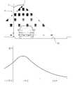
종래의 가로등(10)은 도 1에 도시된 바와 같이 지면으로부터 대략 8~12M정도의 높이를 가지는 폴대(5)의 상단에 조명용 전구(3)를 설치하여 아래의 도로 사방 을 전체적으로 조명하도록 이루어진다.
또한, 상기와 같은 가로등은 도 2에 도시된 바와 같이 일정간격으로 설치되어 도로를 비추도록 이루어진다.In addition, the street light as described above is installed at a predetermined interval as shown in Figure 2 is made to light the road.
그러나, 종래와 같은 가로등은 다음과 같은 문제점이 있다.However, the conventional street light has the following problems.
첫째, 종래의 가로등은 하나의 가로등으로 넓은 범위를 조명하기 위하여 높은 위치에 설치되는데, 그에 따라 도로면과의 거리가 멀게 되므로 도로면을 충분하게 밝히기 위해서는 고광량의 전구가 필요하게 되어 설치비용 및 수명과 전력사용에서 불리한 점이 있다.First, a conventional street light is installed at a high position in order to illuminate a wide range with a single street light, and thus the distance from the road surface becomes far, so that a high-light bulb is required to brighten the road surface. There are disadvantages in life and power usage.
둘째, 광원과 도로면과의 거리가 멀어 안개 발생시 안개의 물방울에 의해 산란되어 노면을 충분히 조명하는 목적을 달성하기 불리한 조명방식이다.Secondly, the distance between the light source and the road surface is far, which is scattered by the water droplets of the fog when the fog is generated is an unfavorable lighting method to achieve the purpose of sufficiently illuminating the road surface.
셋째, 광원이 도로의 상부에서 하부를 향하여 조명하는 방식이므로, 도 2에 도시된 바와 같이 광원의 직하부는 밝기가 규정보다 밝은 핫스팟(Hot Spot)이 형성되며, 멀어질수록 밝기가 떨어지게 되어 도로가 균일하게 조명되지 않는 문제점이 있다.Third, since the light source illuminates from the upper part of the road toward the lower part, as shown in FIG. 2, a hot spot having a brighter brightness than a prescribed level is formed in the lower part of the light source, and as the distance goes away, the brightness decreases. There is a problem that is not uniformly illuminated.
넷째, 또한, 가로등에 의해서 조명되는 범위가 광원을 중심으로 하여 둥그렇게 형성되므로, 조명이 필요치 않은 도로 외측까지 후사광에 의해 조명되어 야간에 생물 또는 곤충이 야간에도 빛을 받게 되어 생태계에 교란이 발생하는 문제점도 있다.Fourthly, since the range illuminated by the street light is roundly formed around the light source, it is illuminated by the rear light to the outside of the road where lighting is not required, so that the creature or insect gets light at night and disturbs the ecosystem. There is also a problem that occurs.
다섯째, 광원의 위치가 운전자의 시야보다 상측에 위치되므로 운전자에게 직사광이 조사되어 운전 중 눈부심을 발생하게 할 수 있어 안전운전을 방해한다.Fifth, since the position of the light source is located above the driver's field of vision, direct light is irradiated to the driver, causing glare during driving, which hinders safe driving.
본 발명은 상기와 같은 문제점을 해결하기 위한 것으로, 본 발명은 도로를 균일하게 밝히면서 운전자의 눈부심을 야기하지 않으며 생태계의 교란이 없는 비대칭 단면의 바타입 렌즈 및 이를 이용한 광원모듈을 제공하는 것을 과제로 한다.The present invention is to solve the above problems, the present invention is to provide a light source module using asymmetric cross-section bar type lens and the same without causing the driver glare while brightening the road uniformly and without ecosystem disturbance .
상기와 같은 과제를 해결하기 위하여, 본 발명의 일 형태에 따르면, 일측방향으로 길이방향을 가지며, 후측에 구비되는 광원으로부터 발광되는 빛이 수광되도록 형성되는 입사면, 상기 입사면의 대향되는 측에 상기 입사면에서 입사된 광이 방사되며, 방사되는 빛의 광량이 어느 한 측으로 편중되도록 비대칭 단면의 굴곡진 표면으로 형성되는 방사면을 포함하여 이루어지는 비대칭 단면의 바타입 렌즈가 제공된다.In order to solve the above problems, according to one embodiment of the present invention, the incident surface having a longitudinal direction in one direction and formed so as to receive light emitted from a light source provided on the rear side, on the side opposite to the incident surface There is provided a bar type lens having an asymmetrical cross section including a radiation surface formed with a curved surface having an asymmetrical cross section so that light incident on the incident surface is emitted and the amount of light emitted is biased to either side.
그리고, 상기 방사면의 상부측에서 방사되는 광량이 하부측에서 방사되는 광량보다 크도록 빛이 굴절되도록 이루어질 수 있다.The light may be refracted such that the amount of light emitted from the upper side of the emission surface is greater than the amount of light emitted from the lower side.
상기 방사면은, 상부측의 곡률반경이 하부측의 곡률반경보다 짧은 형상의 단면을 이루도록 형성될 수 있다.The radial surface may be formed such that the radius of curvature of the upper side forms a cross section of a shape shorter than the radius of curvature of the lower side.
상기 방사면은, 상부측의 곡률중심이 하부측의 곡률중심보다 아래에 위치되도록 이루어질 수 있다.The radiation surface may be such that the center of curvature of the upper side is located below the center of curvature of the lower side.
상기 방사면의 상측으로 연장되고, 빛이 방사되는 면이 평면인 평면부가 더 형성될 수 있다.A flat portion extending upward of the radiation surface and having a plane on which light is emitted may be further formed.
한편, 본 발명의 다른 형태에 따르면, 빛을 발광하며, 횡방향으로 길이방향을 갖도록 이루어지는 광원, 후측면에 상기 광원으로부터 발광되는 빛이 수광되는 입사면이 형성되고, 상기 입사면의 대향되는 측에 상기 입사면에서 입사된 광이 방사되며, 방사되는 빛의 광량이 어느 한 측으로 편중되도록 비대칭 단면의 굴곡진 표면으로 형성되는 방사면을 포함하여 이루어지며 일측방향으로 길이방향을 갖도록 형성되는 비대칭 단면의 바타입 렌즈를 포함하여 이루어지는 도로 조명장치의 광원모듈이 제공된다.On the other hand, according to another aspect of the present invention, a light source that emits light and has a longitudinal direction in the transverse direction, and an incident surface on which the light emitted from the light source is received is formed on the rear side, and the side opposite to the incident surface. Asymmetrical cross-section is formed to have a longitudinal direction in one direction and comprises a radiation surface is formed in the curved surface of the asymmetric cross-section so that the light incident from the incident surface is radiated to the one side of the light emitted There is provided a light source module of a road lighting apparatus comprising a bar type lens.
상기 방사면은, 상부측의 곡률중심이 하부측의 곡률중심보다 아래에 위치되도록 이루어질 수 있다.The radiation surface may be such that the center of curvature of the upper side is located below the center of curvature of the lower side.
상기 비대칭 단면의 바타입 렌즈는, 상기 방사면의 상부측에서 방사되는 광량이 상기 방사부의 하부측에서 방사되는 광량보다 크도록 이루어질 수 있다.The bar-type lens of the asymmetrical cross section may be configured such that the amount of light emitted from the upper side of the emission surface is greater than the amount of light emitted from the lower side of the emission portion.
또한, 상기 굴곡진 방사면의 상측으로 연장되고, 빛이 방사되는 면이 평면인 평면부가 더 형성될 수 있다.In addition, a planar portion extending above the curved radiation surface and having a plane on which the light is emitted may be further formed.
상기 입사면은, 상기 입사면에 수직한 법선이 도로면을 향하도록 경사지게 형성될 수 있다.The incident surface may be formed to be inclined such that a normal line perpendicular to the incident surface faces a road surface.
또한, 상기 비대칭 단면의 바타입 렌즈의 배면에 결합되며, 상기 광원과 연접되고, 후면에 상측을 향하여 연장된 방열핀이 형성되어 상기 광원에서 발생된 열을 방열하는 히트싱크가 더 구비될 수 있다.In addition, a heat sink coupled to the rear surface of the bar-type lens of the asymmetrical cross section and connected to the light source and extending toward the upper side is formed on the rear surface to radiate heat generated from the light source.
상기와 같은 본 발명에 따른 비대칭 단면의 바타입 렌즈 및 이를 이용한 가 로등용 광원모듈에 따르면 다음과 같은 효과가 있다.According to the bar-type lens of the asymmetric cross section and the street light module using the same according to the present invention as described above has the following effects.
첫째, 광원으로써 LED소자를 사용하여, 전력사용량이 줄어들며, 광원의 수명이 향상되므로 운용비가 줄어들을 수 있다.First, using the LED element as a light source, the power consumption is reduced, and the operating cost of the light source can be improved, thereby reducing the operating cost.
둘째, 광원이 횡으로 배열되므로, 도로를 보다 균일하게 밝힐 수 있으며,Second, because the light sources are arranged laterally, you can brighten the road more evenly.
셋째, 상기 렌즈가 빛을 굴절시켜 조사각 범위 중 상측 일부 범위에 광량을 집중할 수 있어 조사면이 먼 곳에 광량을 집중할 수 있으므로 도로의 폭 방향으로 보다 균일하게 밝힐 수 있어 종합 균제도를 만족할 수 있다.Third, since the lens refracts the light to concentrate the amount of light in a part of the upper side of the irradiation angle range, the light can be concentrated at a far distance from the irradiation surface, so that the lens can be more uniformly lighted in the width direction of the road, thereby satisfying the overall uniformity.
셋째, 도로용 조명장치가 높은 폴대에 세워지는 것이 아니라 1m 내외 높이의 도로 난간이나 중앙 분리대 등에 구비되므로, 설치높이가 낮아 도로와의 거리가 줄어듦으로 인해 손실되는 광량이 적으므로, 종래보다 저광량의 광원 사용시에도 충분한 조명이 가능한 장점이 있으며, 차선유도기능도 수행할 수 있다.Third, since the lighting device for the road is not built on a high pole, but is provided on a road rail or a center separator of about 1m in height, since the installation height is low, the amount of light lost due to the decrease in the distance from the road is low. Even when the light source is used, there is an advantage that sufficient illumination is possible, and it can also perform a lane induction function.
넷째, 도로용 조명장치의 설치높이가 1m내외로 낮으므로, 운전자의 눈높이보다 낮게 되어 운전자의 야간 눈부심을 방지하는 효과가 있다.Fourth, since the installation height of the road lighting device is less than about 1m, it is lower than the eye level of the driver has the effect of preventing the night glare of the driver.
다섯째, 도로용 조명장치의 설치 높이가 낮으므로, 안개 발생시 산란되는 광이 상대적으로 적어 보다 효과적으로 조명이 가능하다.Fifth, since the installation height of the road lighting device is low, the light scattered during the generation of fog is relatively small, which enables more efficient lighting.
여섯째, 렌즈를 길이방향으로 복수개 연접하여 광원모듈을 형성할 수 있어 렌즈의 길이가 광원모듈의 길이보다 짧게 형성할 수 있어 렌즈의 제작이 용이하다.Sixth, it is possible to form a light source module by connecting a plurality of lenses in the longitudinal direction, the length of the lens can be formed shorter than the length of the light source module it is easy to manufacture the lens.
일곱째, 빛을 굴절시켜 도로면만을 비추므로 광량이 도로면으로 집중되어 도로를 보다 밝게 비출 수 있다.Seventh, because the light is refracted to illuminate only the road surface, the amount of light can be concentrated on the road surface to brighten the road.
여덟째, 후사광이 없으므로 도로 주변의 식물 및 곤충이 야간에 조명되지 않 아 생태계의 교란을 야기하지 않는 장점이 있다.Eighth, because there is no rear light, there is an advantage that plants and insects around the road are not illuminated at night, which does not cause disturbance of the ecosystem.
아홉째, 광원모듈의 각도를 조절할 수 있어 조사각의 조절이 용이하다.Ninth, the angle of the light source module can be adjusted to facilitate the adjustment of the irradiation angle.
열 째, 방열핀이 상측을 향하도록 연장되어 있어 열발산 효과가 향상되는 효과가 있다.Tenth, there is an effect that the heat dissipation fin is extended to the upper side to improve the heat dissipation effect.
이하 본 발명의 목적이 구체적으로 실현될 수 있는 본 발명의 바람직한 실시예를 첨부된 도면을 참조하여 설명한다. 본 실시예를 설명함에 있어서, 동일 구성에 대해서는 동일 명칭 및 동일 부호가 사용되며 이에 따른 부가적인 설명은 생략하기로 한다.DETAILED DESCRIPTION Hereinafter, exemplary embodiments of the present invention will be described in detail with reference to the accompanying drawings. In the description of this embodiment, the same name and the same reference numerals are used for the same configuration and additional description thereof will be omitted.
본 발명의 일 실시예에 따른 비대칭 단면의 바타입 렌즈(이하, '렌즈'라 칭하기로 함)는 도 3 및 도 4에 도시된 바와 같이, 입사면(110)과 방사면(120)을 포함하여 이루어질 수 있다.The bar-type lens of the asymmetric cross section (hereinafter referred to as the "lens") according to the exemplary embodiment of the present invention includes an
상기 입사면(110)은 광원(90)으로부터 발광된 빛이 입사하여 수광되는 면이다. 일반적으로, 상기 광원(90)은 상기 입사면(110)과 마주보는 면에 구비된다.The
상기 방사면(120)은 상기 입사면(110)의 대향된 측면에 형성되며, 상기 입사면(110)으로부터 수광된 빛이 굴절방사되도록 굴곡지게 형성된다.The
이 때, 상기 방사면(120)은 방사되는 빛이 균일하게 퍼지도록 방사되는 것이 아니라, 방사되는 빛이 어느 한 측으로 편중되어 광량의 차이가 나도록 단면이 비대칭을 이루도록 형성될 수 있다.In this case, the
좀 더 바람직하게는 상기 방사면(120)은 상부측(126)에서 방사되는 빛의 세 기가 하부측(121)에서 방사되는 빛의 세기보다 강하도록 굴곡지게 형성되는 것이다.More preferably, the
이를 위하여, 상기 방사면(120)은 도 3에 도시된 바와 같이, 상부측(126)의 곡률과 하부측(121)의 곡률이 서로 다르도록 형성되는 것이 바람직하다.To this end, the
좀 더 자세하게는 상기 방사면(120)의 상부측 곡률반경(Ru)이 하부측의 곡률반경(Rl)보다 짧으며, 상부측 곡률중심(Cu)이 하부측 공률중심(Cl)보다 하측에 위치되는 형상의 단면을 이루는 것이다.More specifically, the upper curvature radius Ru of the
렌즈(100) 내부의 밀도가 공기의 밀도보다 높고, 상부측의 곡률반경(Ru)이 하부측의 곡률반경(Rl)보다 짧으며, 상부측의 곡률중심(Cu)이 하부측의 곡률중심(Cl)의 하측에 위치되므로, 빛이 방사면(120)을 통하여 방사될 때, 도 3에 도시된 바와 같이, 상기 방사면(120)에서 상부측으로 굴절된다.The density inside the
즉, 빛의 원래 진행방향(96)과 상기 방사면(120)의 해당지점에 수직하는 법선(n)과 이루는 각을 θ1 이라 하고, 상기 방사면(120)에서 굴절되는 빛의 진행방향(98)과 상기 방사면(120)의 해당지점에 수직하는 법선(n)이 이루는 각을 θ2 라고 할 때, 상기 θ2가 θ1 보다 작도록 상기 방사면(120)에서 빛이 굴절되는 것이다.That is, the angle formed between the original traveling
따라서, 상기 방사면(120)의 상부측(126)에서 방사되는 광량이 하부측(121)에서 방사되는 광량보다 많다.Therefore, the amount of light emitted from the
또한, 방사면(120)의 굴곡진 면에서 상부측으로 연장되고, 빛이 방사되는 면이 평면인 평면부(130)가 더 형성될 수 있다. 도 3에 도시된 바와 같이, 상기 평면 부(130)에서는 방사되는 빛이 방사면(120)의 하부측(121)을 향하는 방향으로 굴절된다. 따라서, 상기 렌즈(100)에서 방사되는 빛이 조사각 범위 중 상측 일부 범위에 집중될 수 있다.In addition, a
한편, 광원(90)으로부터 빛이 입사되는 입사면(110) 또한 경사지게 형성될 수도 있다. 좀 더 자세하게는, 도 4에 도시된 바와 같이, 상기 입사면(110)에 수직한 법선(n)이 하부측을 향하도록 경사지게 형성되는 것이다.Meanwhile, the incident surface 110 through which light is incident from the
따라서, 상기 광원(90)으로부터 발광되어 상기 입사면(110)에 입사되는 빛의 조사각 범위 중, 상기 입사면(110)과 수직하는 각도 보다 상측범위의 각도로 입사면(110)에 입사되는 빛은 상기 렌즈(100)의 상측부를 향하여 굴절되며, 하측범위의 각도로 입사되는 빛은 상기 렌즈(100)의 하측부를 향하여 굴절된다.Therefore, the light incident from the
즉, 빛의 원래 진행방향(97)과 상기 입사면(110)의 해당지점에 수직하는 법선(n)과 이루는 각을 θ3 이라 하고, 상기 입사면(110)에서 굴절되는 빛의 진행방향(99)과 상기 입사면(110)의 해당지점에 수직하는 법선(n)이 이루는 각을 θ4 라고 할 때, 상기 θ4가 θ3 보다 크도록 상기 입사면에서 빛이 굴절되는 것이다.That is, the angle formed between the original traveling
그런데, 상기 입사면(110)이 법선(n)이 하부측을 향하도록 경사지므로, 상기 입사면(110)에 입사되어 굴절되는 빛 중 상부측으로 굴절되는 양이 하부측으로 굴절되는 양보다 많다.However, since the
또한, 상기 렌즈(100)는 도 5에 도시된 바와 같이 횡방향으로 길이방향을 갖도록 형성된다. 또한, 상기 렌즈(100)의 양 측면(140)은 평면으로 형성되어 복수 개의 렌즈가 서로 연속적으로 연접되도록 이루어질 수 있다.In addition, the
따라서, 도 6에 도시된 바와 같이, 상기 입사면(110) 및 방사면(120)에 의해 조사각 범위 중 상측범위로 방사되는 광량이 더 많게 된다. 또한, 상기 렌즈(100)의 상측을 향하는 빛이 상기 평면부(130)에 의해 상기 평면부(130)의 평면이 바라보는 방향으로 굴절되므로, 상기 렌즈(100)의 평면부(130)가 바라보는 방향으로 광량이 집중될 수 있다.Therefore, as illustrated in FIG. 6, the amount of light emitted by the
이하, 본 발명에 따른 상기한 비대칭 단면의 바타입 렌즈를 이용한 도로 조명장치의 광원모듈의 일 실시예를 설명하기로 한다.Hereinafter, an embodiment of a light source module of a road lighting apparatus using the bar type lens of the asymmetric cross section according to the present invention will be described.
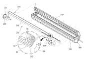
본 실시예에 따른 도로 조명장치의 광원모듈(200)은 도 7에 도시된 바와 같이, 광원(90)과 비대칭 단면의 바타입 렌즈(100) 및 히트싱크(210)를 포함하여 이루어질 수 있다.As shown in FIG. 7, the
상기 광원(90)은 횡방향으로 길이방향을 가지도록 이루어질 수 있다. 또한, 상기 광원(90)은 LED 소자(92)가 횡방향으로 복수개 배열된 기판(94)으로 이루어질 수 있다. 물론, 이에 한정되는 것은 아니며, LED가 아닌 다른 형식의 광원을 사용할 수 있다.The
상기 비대칭 단면의 바타입 렌즈(100)는, 전술한 실시예의 비대칭 단면의 바타입 렌즈(100)와 실질적으로 동일하며, 상기 광원(90)과 동일한 길이방향을 가지도록 형성되며, 상기 렌즈(100)의 설명은 전술한 비대칭 단면의 바타입 렌즈(100) 의 설명으로 갈음하기로 한다.The
이 때, 상기 렌즈(100)는 양 측면이 평면으로 형성되어, 소정길이의 렌즈(100)가 측면이 서로 연접되어 보다 긴 길이의 비대칭 단면의 바타입 렌즈군을 형성하도록 이루어질 수 있다.At this time, both sides of the
상기 히트싱크(210)는, 상기 광원(90)이 길이방향과 동일한 길이방향을 가지도록 형성되며, 전면에 상기 광원(90)이 연접되게 수용되며, 그리고, 상기 광원(90)이 수용된 부분의 상측과 하측에는 상기 렌즈(100)가 슬라이딩 방식으로 결합될 수 있는 렌즈 결합홈(212)이 길이방향을 따라 형성된다.The
또한, 후면에는 상기 광원(90)으로부터 전도된 열이 방열되는 방열핀(214)이 상측을 향하여 연장되도록 형성된다.In addition, the rear surface is formed so that the
그리고, 상기 히트싱크(210)의 상측에 전면을 향하여 소정길이 연장된 플랜지부(216)가 형성될 수 있다.In addition, a
한편, 상기와 같이 이루어진 가로등용 광원모듈(200)은 외관을 이루는 하우징(300) 내부에 각도조절이 가능하게 구비될 수 있다.On the other hand, the
상기와 같이 가로등용 광원모듈(200)의 각도조절을 가능하게 하기 위하여, 상기 하우징(300)의 내부 양 측에는 상기 가로등용 광원모듈(200)의 양 단을 회전가능하게 지지하는 마운트(220)가 각각 구비될 수 있다.In order to enable the angle adjustment of the
상기 마운트(220)는, 상기 하우징(300)에 고정되는 고정판(222)과, 상기 고정판(222)에 회전가능하게 축결합되며, 소정각도구간별로 각도의 고정이 가능한 회전판(226)을 포함하여 이루어질 수 있다.The mount 220 includes a fixed plate 222 fixed to the
즉, 상기 고정판(222)의 일면에 제1돌기(224)가 복수개 형성되며, 상기 제1돌기(224)가 형성된 고정판(222)의 일면과 마주보며 연접되는 상기 회전판(226)의 일면에 상기 제1돌기(224)와 치합되는 제2돌기(228)가 복수개 형성되는 것이다.That is, a plurality of
따라서, 상기 회전판(226)이 상기 고정판(222)에 압착되면, 상기 제1돌기(224)와 제2돌기(228)에 의해 상기 회전판(226)의 각도가 고정되며, 외력에 의해 상기 회전판(226)에 일정 힘 이상의 회전력이 가해질 경우 상기 제2회전판(226)의 탄성에 의해 상기 제2회전판(226)이 회전되어 각도가 조절되는 것이다.Therefore, when the rotating plate 226 is pressed to the fixing plate 222, the angle of the rotating plate 226 is fixed by the
또한, 상기 회전판(226)의 외주면에는 상기 히트싱크(210)의 플랜지(216)와 겹쳐지도록 연장되는 결합부(229)가 형성되어 상기 히트싱크(210)의 플랜지(216)와 상기 회전판(226)의 결합부(229)가 나사결합되어 상기 가로등용 광원모듈(200)이 각도조절 가능하게 결합되는 것이다.In addition, the outer peripheral surface of the rotating plate 226 is formed with a
한편, 상기 하우징(300)은 상기 가로등용 광원모듈(200)의 착탈이 가능하도록 상측면에 뚜껑(310)이 회전가능하게 결합되며, 상기 가로등용 광원모듈(200)의 빛이 투과되도록 전면에 투명창(320)이 구비된다.On the other hand, the
상기와 같은 가로등용 광원모듈(200)은 별도의 폴대에 설치되지 아니하고, 도 8에 도시된 바와 같이, 도로(20)의 측방에 설치되는 도로난간(30), 다리난간 또는 가이드레일이나 중앙분리대에 도로를 따라 소정간격으로 설치될 수 있다.The
상기와 같이 난간(30)이나 가이드 레일에 설치될 경우 상기 가로등용 광원모듈(200)설치높이는 도로면으로부터 1m내외의 좀 더 바람직하게는 1.5m이하의 운전자의 눈 높이보다 낮은 위치에 설치되는 것이 바람직하다.When installed on the
따라서, 상기 가로등용 광원모듈(200)을 도로난간 등에 낮은 위치에서 도로만 비추도록 조명함으로써 가로등용 광원모듈(200)과 도로면(20)까지의 거리를 짧게 하여 운전자는 물론 보행자 등 도로 이용자의 시야를 방해하는 빛 반사를 방지함은 물론 도로의 밝기를 향상시킬 수 있다.Therefore, by illuminating the street
또한, 도 6에 도시된 바와 같이, 상기 가로등용 광원모듈의 조사각 범위 중 상부측에 소정범위에 광량이 집중되므로, 설치된 장소로부터 먼 지점을 보다 밝게 비출 수 있어, 도로를 보다 균일하게 밝혀줄 수 있다.In addition, as shown in Figure 6, since the amount of light is concentrated in a predetermined range on the upper side of the irradiation angle range of the light source module for the street light, it is possible to more brightly illuminate a point far from the installed place, to make the road more uniform Can be.
또한, 상기 투명창(320)이 구비된 부분은 자동차 전조등의 빛이 반사될 수 있는데, 반사된 빛이 전방으로 향하여 전방 운전자의 시야를 방해하지 않도록, 도로면을 향하도록 경사지게 형성될 수 있다. 따라서, 자동차 전조등의 빛이 상기 투명창(320)에서 반사되더라도 상기 투명창(320)의 경사에 의해 반사된 빛이 도로면을 향하므로, 전방의 다른 운전자의 시야를 방해하지 않을 뿐만 아니라, 반사된 빛이 도로면을 비추게 되어 도로면이 더욱 밝게 비출 수 있다.In addition, the portion provided with the
이상과 같이 본 발명에 따른 바람직한 실시예를 살펴보았으며, 앞서 설명된 실시예 이외에도 본 발명이 그 취지나 범주에서 벗어남이 없이 다른 특정 형태로 구체화 될 수 있다는 사실은 해당 기술에 통상의 지식을 가진 이들에게는 자명한 것이다. 그러므로, 상술된 실시예는 제한적인 것이 아니라 예시적인 것으로 여겨져야 하고, 이에 따라 본 발명은 상술한 설명에 한정되지 않고 첨부된 청구항의 범주 및 그 동등 범위 내에서 변경될 수도 있다.As described above, the preferred embodiments of the present invention have been described, and the fact that the present invention can be embodied in other specific forms in addition to the above-described embodiments without departing from the spirit or scope thereof has ordinary skill in the art. It is obvious to them. Therefore, the above-described embodiments should be regarded as illustrative rather than restrictive, and thus, the present invention is not limited to the above description and may be modified within the scope of the appended claims and their equivalents.
도 1은 도 1은 종래의 가로등 및 가로등에 의해 조명되는 도로의 밝기를 도시한 도면;1 is a view showing the brightness of the road is illuminated by a conventional street lamp and street lamp;
도 2는 도 1을 상부에서 바라본 도면;2 is a view from above of FIG. 1;
도 3은 본 발명의 일 실시예에 따른 비대칭 단면의 바타입비대칭 단면의 바타입 렌즈의 단면을 도시한 단면도;3 is a cross-sectional view showing a cross-section of the bar type lens of the asymmetric cross-section bar type asymmetric cross section according to an embodiment of the present invention;
도 4는 도 3의 비대칭 단면의 바타입 렌즈의 입사면에서 빛이 굴절되는 예를 도시한 단면도;FIG. 4 is a cross-sectional view illustrating an example in which light is refracted at an incident surface of a bar type lens having an asymmetric cross section of FIG. 3;
도 5는 도 3의 사시도;5 is a perspective view of FIG. 3;
도 6은 도 3의 비대칭 단면의 바타입 렌즈에 의해 방사되는 빛의 조사각 범위 중 밝기 분포를 도시한 도면;FIG. 6 is a diagram illustrating a brightness distribution among irradiation angle ranges of light emitted by the bar type lens of the asymmetric cross-section of FIG. 3;
도 7은 본 발명의 일 실시예에 따른 도로 조명장치의 광원모듈 및 하우징을 도시한 분해 사시도;7 is an exploded perspective view illustrating a light source module and a housing of a road lighting apparatus according to an embodiment of the present invention;
도 8은 도 7의 도로 조명장치의 광원모듈에 의해 조명되는 도로의 밝기를 도시한 도면 이다.FIG. 8 is a view illustrating brightness of a road illuminated by a light source module of the road lighting apparatus of FIG. 7.
<도면의 주요 부분에 대한 부호 설명><Description of the symbols for the main parts of the drawings>
3: 조명용 전구 5: 폴대 30: 난간3: lighting bulb 5: pole 30: handrail
90: 광원 92: LED 94: 기판90: light source 92: LED 94: substrate
96: 방사면에서의 빛의 원래 진행방향96: original direction of light at the radial plane
97: 입사면에서의 빛의 원래 진행방향97: original direction of travel of the light at the plane of incidence
98: 방사면에서 굴절된 빛의 진행방향98: direction of propagation of light refracted at the radiation plane
99: 입사면에서 굴절된 빛의 진행방향99: propagation direction of light refracted at the incident surface
100: 비대칭 단면의 바타입 렌즈 110: 입사면100: bar type lens with an asymmetric cross section 110: incident surface
120: 방사면 121: 방사면의 하부측120: radiation surface 121: lower side of the radiation surface
126: 방사면의 상부측 130: 평면부 140: 측면126: upper side of the radiation surface 130: plane portion 140: side
200: 광원모듈 210: 히트싱크 212: 렌즈 결합홈200: light source module 210: heat sink 212: lens coupling groove
214: 방열핀 216: 플랜지 220: 마운트214: heat sink fin 216: flange 220: mount
222: 고정판 224: 제1돌기 226: 회전판222: fixing plate 224: first projection 226: rotating plate
228: 제2돌기 229: 결합부 300: 하우징228: second projection 229: coupling portion 300: housing
310: 뚜껑 320: 투명창 n: 표면에 수직한 법선310: lid 320: transparent window n: normal normal to the surface
θ1: 빛의 원래 진행방향과 상기 방사면의 해당지점에 수직하는 법선(n)과 이루는 각θ1: angle formed by the normal direction of light and the normal line n perpendicular to the corresponding point of the radiation plane
θ2: 방사면에서 굴절되는 빛의 진행방향과 상기 방사면의 해당지점에 수직하는 법선이 이루는 각θ2: angle formed by the direction of light refracted by the radiation plane and a normal perpendicular to the corresponding point of the radiation plane
θ3: 빛의 원래 진행방향과 상기 입사면의 해당지점에 수직하는 법선(n)과 이루는 각θ3: angle formed by the normal traveling direction of light and the normal line n perpendicular to the corresponding point of the incident surface
θ4: 입사면에서 굴절되는 빛의 진행방향과 상기 입사면의 해당지점에 수직하는 법선이 이루는 각θ4: angle formed by the direction of light refracted by the incident surface and a normal perpendicular to the corresponding point of the incident surface
Claims (11)
Translated fromKoreanPriority Applications (2)
| Application Number | Priority Date | Filing Date | Title |
|---|---|---|---|
| KR1020090065847AKR100936430B1 (en) | 2009-07-20 | 2009-07-20 | Bar type lens of asymmetrical cross section and light source module of road lighting device using same |
| PCT/KR2010/003343WO2011010790A1 (en) | 2009-07-20 | 2010-05-26 | Bar type lens with asymmetric cross section and light source module for road lighting device using same |
Applications Claiming Priority (1)
| Application Number | Priority Date | Filing Date | Title |
|---|---|---|---|
| KR1020090065847AKR100936430B1 (en) | 2009-07-20 | 2009-07-20 | Bar type lens of asymmetrical cross section and light source module of road lighting device using same |
Publications (1)
| Publication Number | Publication Date |
|---|---|
| KR100936430B1true KR100936430B1 (en) | 2010-01-12 |
Family
ID=41809685
Family Applications (1)
| Application Number | Title | Priority Date | Filing Date |
|---|---|---|---|
| KR1020090065847AExpired - Fee RelatedKR100936430B1 (en) | 2009-07-20 | 2009-07-20 | Bar type lens of asymmetrical cross section and light source module of road lighting device using same |
Country Status (2)
| Country | Link |
|---|---|
| KR (1) | KR100936430B1 (en) |
| WO (1) | WO2011010790A1 (en) |
Cited By (11)
| Publication number | Priority date | Publication date | Assignee | Title |
|---|---|---|---|---|
| EP2423569A1 (en)* | 2010-08-24 | 2012-02-29 | Samsung LED Co., Ltd. | Optical Lens, LED Module Having the Optical Lens, and Lighting Apparatus Having the LED Module |
| WO2011136522A3 (en)* | 2010-04-30 | 2012-03-08 | 주식회사 이지라이팅 | Led illuminating module |
| WO2012089077A1 (en)* | 2010-12-30 | 2012-07-05 | 北京朗波尔光电股份有限公司 | Led light source assembly and led light fixture applied to low-location lighting |
| KR101251441B1 (en)* | 2011-03-31 | 2013-04-05 | 한국광기술원 | Eccentricity condenser lens for luminous element and illumination system |
| KR101307731B1 (en)* | 2011-12-19 | 2013-09-11 | 엘지이노텍 주식회사 | Member for controlling luminous flux, light emitting apparatus and display device |
| CN103363314A (en)* | 2012-03-26 | 2013-10-23 | 深圳科宏健半导体照明有限公司 | Stripped LED lamp with dissymmetric light distribution |
| KR101360004B1 (en)* | 2013-06-27 | 2014-02-07 | 주식회사 이엘 | Antiglare type compound refractive lens for lighting unit and street light apparatus comprising the same |
| KR101482155B1 (en)* | 2013-10-29 | 2015-01-14 | 노명재 | Light diffusing lens for luminous intensity distribution control of led groups, and led groups illuminant included the same |
| WO2019017719A1 (en)* | 2017-07-21 | 2019-01-24 | 주식회사 우노이앤피 | Led lighting module for low streetlight and led lens |
| KR102432621B1 (en)* | 2021-03-25 | 2022-08-16 | 더좋은생활 주식회사 | Road lighting method with flat cut-off lens |
| KR20220169853A (en)* | 2021-06-21 | 2022-12-28 | 이유로 | Roadkill prevention system for wild animal |
Families Citing this family (2)
| Publication number | Priority date | Publication date | Assignee | Title |
|---|---|---|---|---|
| FR2976999B1 (en)* | 2011-06-21 | 2014-10-24 | Jacques Sabater | DEVICE FOR DIRECT LIGHTING OF A SURFACE USING LIGHT EMITTING DIODES |
| IT201900010713A1 (en)* | 2019-07-02 | 2021-01-02 | Itl S R L | Extruded lens for light radiation distribution, lamp, lamp holder assembly and merchandise display |
Citations (4)
| Publication number | Priority date | Publication date | Assignee | Title |
|---|---|---|---|---|
| JPH05190907A (en)* | 1991-07-17 | 1993-07-30 | Precision Solar Controls Inc | Light-emitting diode lamp with dioptric lens element |
| US20020080615A1 (en)* | 2000-12-22 | 2002-06-27 | Thomas Marshall | LED collimation optics with improved performance and reduced size |
| US20040070855A1 (en)* | 2002-10-11 | 2004-04-15 | Light Prescriptions Innovators, Llc, A Delaware Limited Liability Company | Compact folded-optics illumination lens |
| KR100661261B1 (en)* | 2005-05-23 | 2006-12-26 | 주식회사 세코닉스 | LED diffused lens |
- 2009
- 2009-07-20KRKR1020090065847Apatent/KR100936430B1/ennot_activeExpired - Fee Related
- 2010
- 2010-05-26WOPCT/KR2010/003343patent/WO2011010790A1/enactiveApplication Filing
Patent Citations (4)
| Publication number | Priority date | Publication date | Assignee | Title |
|---|---|---|---|---|
| JPH05190907A (en)* | 1991-07-17 | 1993-07-30 | Precision Solar Controls Inc | Light-emitting diode lamp with dioptric lens element |
| US20020080615A1 (en)* | 2000-12-22 | 2002-06-27 | Thomas Marshall | LED collimation optics with improved performance and reduced size |
| US20040070855A1 (en)* | 2002-10-11 | 2004-04-15 | Light Prescriptions Innovators, Llc, A Delaware Limited Liability Company | Compact folded-optics illumination lens |
| KR100661261B1 (en)* | 2005-05-23 | 2006-12-26 | 주식회사 세코닉스 | LED diffused lens |
Cited By (17)
| Publication number | Priority date | Publication date | Assignee | Title |
|---|---|---|---|---|
| WO2011136522A3 (en)* | 2010-04-30 | 2012-03-08 | 주식회사 이지라이팅 | Led illuminating module |
| EP2423569A1 (en)* | 2010-08-24 | 2012-02-29 | Samsung LED Co., Ltd. | Optical Lens, LED Module Having the Optical Lens, and Lighting Apparatus Having the LED Module |
| CN102374485A (en)* | 2010-08-24 | 2012-03-14 | 三星Led株式会社 | Optical lens, led module having the optical lens, and lighting apparatus having the led module |
| US8632225B2 (en) | 2010-08-24 | 2014-01-21 | Samsung Electronics Co., Ltd. | Optical lens, LED module having the optical lens, and lighting apparatus having the LED module |
| WO2012089077A1 (en)* | 2010-12-30 | 2012-07-05 | 北京朗波尔光电股份有限公司 | Led light source assembly and led light fixture applied to low-location lighting |
| KR101251441B1 (en)* | 2011-03-31 | 2013-04-05 | 한국광기술원 | Eccentricity condenser lens for luminous element and illumination system |
| KR101307731B1 (en)* | 2011-12-19 | 2013-09-11 | 엘지이노텍 주식회사 | Member for controlling luminous flux, light emitting apparatus and display device |
| CN103363314A (en)* | 2012-03-26 | 2013-10-23 | 深圳科宏健半导体照明有限公司 | Stripped LED lamp with dissymmetric light distribution |
| KR101360004B1 (en)* | 2013-06-27 | 2014-02-07 | 주식회사 이엘 | Antiglare type compound refractive lens for lighting unit and street light apparatus comprising the same |
| KR101482155B1 (en)* | 2013-10-29 | 2015-01-14 | 노명재 | Light diffusing lens for luminous intensity distribution control of led groups, and led groups illuminant included the same |
| WO2019017719A1 (en)* | 2017-07-21 | 2019-01-24 | 주식회사 우노이앤피 | Led lighting module for low streetlight and led lens |
| KR20190010346A (en)* | 2017-07-21 | 2019-01-30 | (주)선린 | Led lens and led lighting module for low street light using the same |
| KR102005347B1 (en)* | 2017-07-21 | 2019-10-01 | (주)선린 | Led lens and led lighting module for low street light using the same |
| US11125404B2 (en) | 2017-07-21 | 2021-09-21 | Uno Enp Co., Ltd. | LED lighting module for low streetlight and LED lens |
| KR102432621B1 (en)* | 2021-03-25 | 2022-08-16 | 더좋은생활 주식회사 | Road lighting method with flat cut-off lens |
| KR20220169853A (en)* | 2021-06-21 | 2022-12-28 | 이유로 | Roadkill prevention system for wild animal |
| KR102684861B1 (en) | 2021-06-21 | 2024-07-12 | 이유로 | Roadkill prevention system for wild animal |
Also Published As
| Publication number | Publication date |
|---|---|
| WO2011010790A1 (en) | 2011-01-27 |
Similar Documents
| Publication | Publication Date | Title |
|---|---|---|
| KR100936430B1 (en) | Bar type lens of asymmetrical cross section and light source module of road lighting device using same | |
| KR101531390B1 (en) | Asymmetric type lens and street lamp comprising the same | |
| US9803821B2 (en) | Vehicle-mounted headlamp | |
| US8256922B2 (en) | Lighting device | |
| JP5800161B2 (en) | LED lamp module | |
| US7997778B2 (en) | Vehicle light | |
| KR101197716B1 (en) | Street lamp unit for lighting road | |
| KR101381862B1 (en) | Automotive lamp assembly | |
| KR20100091467A (en) | Street light using the led | |
| KR101236736B1 (en) | Aspherical lens for a light emitting diode and light source assembly including the same | |
| TW200930591A (en) | Projection-type head lamp capable of compensating for light of dark area | |
| KR101529166B1 (en) | Lamp for vehicle | |
| KR101903067B1 (en) | Lighting Device | |
| KR101460729B1 (en) | Lamp apparatus for an automobile | |
| KR101531462B1 (en) | Reflecting unit for led lamp | |
| KR101021929B1 (en) | Car lamp assembly | |
| KR100962041B1 (en) | Device for light street lighting car lane and sidewalk | |
| KR101979571B1 (en) | Head lamp for vehicles | |
| KR101416471B1 (en) | Lamp apparatus for an automobile | |
| KR101073473B1 (en) | LED fixed frame to improve uniformity and lighting device for streetlight including the same | |
| TWI418741B (en) | Lighting device | |
| KR101959804B1 (en) | Lamp for vehicle | |
| JP2014503111A (en) | Lighting device and lighting fixture having the lighting device | |
| TW201425815A (en) | Lighting emitting diode automobile lamp | |
| JP2003036705A (en) | Lighting equipment |
Legal Events
| Date | Code | Title | Description |
|---|---|---|---|
| A201 | Request for examination | ||
| A302 | Request for accelerated examination | ||
| PA0109 | Patent application | St.27 status event code:A-0-1-A10-A12-nap-PA0109 | |
| PA0201 | Request for examination | St.27 status event code:A-1-2-D10-D11-exm-PA0201 | |
| PA0302 | Request for accelerated examination | St.27 status event code:A-1-2-D10-D17-exm-PA0302 St.27 status event code:A-1-2-D10-D16-exm-PA0302 | |
| D13-X000 | Search requested | St.27 status event code:A-1-2-D10-D13-srh-X000 | |
| D14-X000 | Search report completed | St.27 status event code:A-1-2-D10-D14-srh-X000 | |
| E902 | Notification of reason for refusal | ||
| PE0902 | Notice of grounds for rejection | St.27 status event code:A-1-2-D10-D21-exm-PE0902 | |
| E13-X000 | Pre-grant limitation requested | St.27 status event code:A-2-3-E10-E13-lim-X000 | |
| P11-X000 | Amendment of application requested | St.27 status event code:A-2-2-P10-P11-nap-X000 | |
| P13-X000 | Application amended | St.27 status event code:A-2-2-P10-P13-nap-X000 | |
| E701 | Decision to grant or registration of patent right | ||
| PE0701 | Decision of registration | St.27 status event code:A-1-2-D10-D22-exm-PE0701 | |
| GRNT | Written decision to grant | ||
| PR0701 | Registration of establishment | St.27 status event code:A-2-4-F10-F11-exm-PR0701 | |
| PR1002 | Payment of registration fee | St.27 status event code:A-2-2-U10-U11-oth-PR1002 Fee payment year number:1 | |
| PG1601 | Publication of registration | St.27 status event code:A-4-4-Q10-Q13-nap-PG1601 | |
| FPAY | Annual fee payment | Payment date:20130121 Year of fee payment:4 | |
| PR1001 | Payment of annual fee | St.27 status event code:A-4-4-U10-U11-oth-PR1001 Fee payment year number:4 | |
| PR1001 | Payment of annual fee | St.27 status event code:A-4-4-U10-U11-oth-PR1001 Fee payment year number:5 | |
| PR1001 | Payment of annual fee | St.27 status event code:A-4-4-U10-U11-oth-PR1001 Fee payment year number:6 | |
| LAPS | Lapse due to unpaid annual fee | ||
| PC1903 | Unpaid annual fee | St.27 status event code:A-4-4-U10-U13-oth-PC1903 Not in force date:20160106 Payment event data comment text:Termination Category : DEFAULT_OF_REGISTRATION_FEE | |
| P22-X000 | Classification modified | St.27 status event code:A-4-4-P10-P22-nap-X000 | |
| PC1903 | Unpaid annual fee | St.27 status event code:N-4-6-H10-H13-oth-PC1903 Ip right cessation event data comment text:Termination Category : DEFAULT_OF_REGISTRATION_FEE Not in force date:20160106 | |
| P22-X000 | Classification modified | St.27 status event code:A-4-4-P10-P22-nap-X000 | |
| P22-X000 | Classification modified | St.27 status event code:A-4-4-P10-P22-nap-X000 |