KR100936063B1 - Light diffusion - Google Patents
Light diffusionDownload PDFInfo
- Publication number
- KR100936063B1 KR100936063B1KR1020080057756AKR20080057756AKR100936063B1KR 100936063 B1KR100936063 B1KR 100936063B1KR 1020080057756 AKR1020080057756 AKR 1020080057756AKR 20080057756 AKR20080057756 AKR 20080057756AKR 100936063 B1KR100936063 B1KR 100936063B1
- Authority
- KR
- South Korea
- Prior art keywords
- resin
- layer
- light
- light diffusion
- diffusion member
- Prior art date
- Legal status (The legal status is an assumption and is not a legal conclusion. Google has not performed a legal analysis and makes no representation as to the accuracy of the status listed.)
- Expired - Fee Related
Links
Images


Classifications
- G—PHYSICS
- G02—OPTICS
- G02B—OPTICAL ELEMENTS, SYSTEMS OR APPARATUS
- G02B5/00—Optical elements other than lenses
- G02B5/02—Diffusing elements; Afocal elements
- G02B5/0205—Diffusing elements; Afocal elements characterised by the diffusing properties
- G02B5/021—Diffusing elements; Afocal elements characterised by the diffusing properties the diffusion taking place at the element's surface, e.g. by means of surface roughening or microprismatic structures
- G02B5/0215—Diffusing elements; Afocal elements characterised by the diffusing properties the diffusion taking place at the element's surface, e.g. by means of surface roughening or microprismatic structures the surface having a regular structure
- B—PERFORMING OPERATIONS; TRANSPORTING
- B32—LAYERED PRODUCTS
- B32B—LAYERED PRODUCTS, i.e. PRODUCTS BUILT-UP OF STRATA OF FLAT OR NON-FLAT, e.g. CELLULAR OR HONEYCOMB, FORM
- B32B27/00—Layered products comprising a layer of synthetic resin
- B32B27/06—Layered products comprising a layer of synthetic resin as the main or only constituent of a layer, which is next to another layer of the same or of a different material
- B32B27/08—Layered products comprising a layer of synthetic resin as the main or only constituent of a layer, which is next to another layer of the same or of a different material of synthetic resin
- G—PHYSICS
- G02—OPTICS
- G02B—OPTICAL ELEMENTS, SYSTEMS OR APPARATUS
- G02B5/00—Optical elements other than lenses
- G02B5/02—Diffusing elements; Afocal elements
- G02B5/0205—Diffusing elements; Afocal elements characterised by the diffusing properties
- G02B5/0236—Diffusing elements; Afocal elements characterised by the diffusing properties the diffusion taking place within the volume of the element
- G02B5/0242—Diffusing elements; Afocal elements characterised by the diffusing properties the diffusion taking place within the volume of the element by means of dispersed particles
- B—PERFORMING OPERATIONS; TRANSPORTING
- B32—LAYERED PRODUCTS
- B32B—LAYERED PRODUCTS, i.e. PRODUCTS BUILT-UP OF STRATA OF FLAT OR NON-FLAT, e.g. CELLULAR OR HONEYCOMB, FORM
- B32B2305/00—Condition, form or state of the layers or laminate
- B32B2305/30—Fillers, e.g. particles, powders, beads, flakes, spheres, chips
- B—PERFORMING OPERATIONS; TRANSPORTING
- B32—LAYERED PRODUCTS
- B32B—LAYERED PRODUCTS, i.e. PRODUCTS BUILT-UP OF STRATA OF FLAT OR NON-FLAT, e.g. CELLULAR OR HONEYCOMB, FORM
- B32B2307/00—Properties of the layers or laminate
- B32B2307/20—Properties of the layers or laminate having particular electrical or magnetic properties, e.g. piezoelectric
- B32B2307/21—Anti-static
Landscapes
- Physics & Mathematics (AREA)
- General Physics & Mathematics (AREA)
- Optics & Photonics (AREA)
- Chemical & Material Sciences (AREA)
- Dispersion Chemistry (AREA)
- Optical Elements Other Than Lenses (AREA)
- Planar Illumination Modules (AREA)
Abstract
Translated fromKoreanDescription
Translated fromKorean본 발명은 액정 디스플레이 장치(Liquid Crystal Display)에 사용되는 광확산 부재에 관한 것이다.The present invention relates to a light diffusing member for use in a liquid crystal display.
산업 사회가 고도의 정보화 시대로 발전함에 따라 다양한 정보를 표시 및 전달하기 위한 매체로서 전자 디스플레이 장치의 중요성은 나날이 증대되고 있다. 종래에 널리 사용되어 오던 CRT(Cathode Ray Tube)는 설치 공간상의 제약이 커서 대형화가 힘들다는 한계 때문에, 액정 디스플레이(LCD), 플라즈마 디스플레이 패널(PDP), 전계 방사 디스플레이(FED) 및 유기EL과 같은 다양한 평판 디스플레이 장치로 대치되고 있다. 이러한 평판 디스플레이 장치 중에서, 특히, 액정 디스플레이 장치(LCD)의 경우, 액정과 반도체 기술이 복합된 기술 집약적 장치로서 얇고, 가벼우며 소비 전력이 낮은 장점으로 인해, 그 구조 및 제조 기술이 연구 개발되어 왔고, 현재 노트북 컴퓨터, 데스크탑 컴퓨터의 모니터, 휴대용 개인 통신 장치(PDA 및 휴대폰) 등 기존에 액정 디스플레이가 널리 사용되었던 영역뿐만 아니라, 대형화 기술도 점점 그 한계를 뛰어넘고 있어, HD(High Definition) TV급의 대형 TV에까지 응용되고 있는 등 디스플레이의 대명사였던 CRT를 대체 가능한 새로운 디스플 레이 장치로 각광받고 있다.As the industrial society develops into an advanced information age, the importance of the electronic display device as a medium for displaying and transmitting various information is increasing day by day. CRT (Cathode Ray Tube), which has been widely used in the past, has limitations due to large installation space, which makes it difficult to increase the size. Therefore, such as liquid crystal display (LCD), plasma display panel (PDP), field emission display (FED), and organic EL It is being replaced by various flat panel display devices. Among such flat panel display devices, in particular, in the case of liquid crystal display devices (LCDs), due to the advantages of thin, light, and low power consumption as a technology-intensive device in which liquid crystal and semiconductor technologies are combined, its structure and manufacturing technology have been researched and developed. In addition to the areas where liquid crystal displays have been widely used, such as notebook computers, desktop computer monitors, and portable personal communication devices (PDAs and mobile phones), large-scale technology is gradually exceeding its limitations. It is being used as a new display device that can replace CRT, which is synonymous with display, as it is applied to large TV of TV.
이러한 액정 디스플레이(LCD) 장치는 액정 자체가 발광을 할 수 없기 때문에 장치의 후면에 별도의 광원을 설치하여, 각 화소(pixel)에 설치된 액정을 통해 통과광의 세기를 조절하여 계조(contrast)를 구현한다. 이를 보다 구체적으로 살펴보면, 액정 디스플레이 장치는 액정 물질의 전기적 특성을 이용하여 빛의 투과율을 조절하는 장치로, 장치 뒷면의 광원 램프에서 발광하여 각종 기능성 프리즘 필름 또는 시트를 통과하여 균일도와 방향성이 제어된 빛을 컬러 필터를 통과시켜 적, 청, 녹(R, G, B)의 색상을 구현하도록 하고, 전기적인 방법으로 각 화소의 계조(contrast)를 제어하여 화상을 구현하는 간접 발광 방식의 디스플레이 장치로서, 광원을 제공하는 발광 장치는 액정 디스플레이 장치의 휘도 및 균일도 등 화질을 결정하는 중요한 부품이다.In the liquid crystal display (LCD) device, since the liquid crystal itself cannot emit light, a separate light source is installed at the rear of the device to adjust the intensity of the passing light through the liquid crystal installed in each pixel to realize contrast. do. In more detail, the liquid crystal display device is a device for controlling the light transmittance by using the electrical properties of the liquid crystal material, the uniformity and the directionality is controlled by passing through various functional prism films or sheets by emitting light from the light source lamp on the back of the device Indirect light-emitting display device that implements an image by passing light through a color filter to realize red, blue, green (R, G, B) colors, and controlling the contrast of each pixel by an electric method As a light emitting device that provides a light source, it is an important component for determining image quality such as brightness and uniformity of a liquid crystal display device.
상기 발광 장치로는 백라이트 유닛(BLU)이 널리 사용되고 있으며, 일반적으로 냉음극형광램프(CCFL: Cold Cathode Fluorescent Lamp) 등의 복수개의 광원을 사용하여 방출되는 빛을 순차적으로 확산판, 확산 시트 및 프리즘 시트 등의 시트를 통과시켜 액정 패널에 도달하게 한다. 여기서, 확산 시트는 화면 전면에 걸쳐 균일한 광세기를 얻을 수 있도록 하는 동시에 확산 시트 하부에 장착된 광원 등의 장치가 전면에서 보이지 않도록 은폐하는 기능을 수행한다. 한편, 프리즘 시트는 확산 시트를 거친 다양한 방향의 광선을 관측자가 화상을 인식하기에 적합한 시야각(θ) 범위 내로 변환되도록 하는 광 경로 제어 기능을 수행한다.As the light emitting device, a backlight unit (BLU) is widely used, and in general, light emitted from a plurality of light sources, such as a cold cathode fluorescent lamp (CCFL), is sequentially spread on a diffusion plate, a diffusion sheet, and a prism. A sheet such as a sheet is passed through to reach the liquid crystal panel. Here, the diffusion sheet performs a function of obtaining a uniform light intensity over the entire screen, and at the same time concealing a device such as a light source mounted under the diffusion sheet from the front. The prism sheet, on the other hand, performs an optical path control function for causing the light beams from various directions passing through the diffusion sheet to be converted into a range of viewing angle θ suitable for the viewer to recognize the image.
최근 액정 디스플레이 장치는 소비자의 요구에 부응하고자 경량, 박형, 저소 비전력화 되고 있는데, 액정 디스플레이 장치를 슬림하게 제조하기 위한 한 방법으로 액정 디스플레이 장치에 필수적인 구성요소인 상기 백라이트 유닛의 두께를 감소시킬 수 있다.Recently, liquid crystal display devices are becoming lightweight, thin, and low power consumption in order to meet consumer demand. As a method for manufacturing a slim LCD display device, the thickness of the backlight unit, which is an essential component of the liquid crystal display device, can be reduced. have.
그러나 상기 백라이트 유닛은 액정 패널까지 빛이 도달되도록 빛의 효율을 높이기 위하여 여러 장의 시트를 장착하고 있어 기본적으로 어느 정도의 두께는 필수적으로 갖게 되고, 액정 디스플레이 장치의 두께를 일정 수준의 두께 이하로 감소시키는 데는 한계가 있다.However, the backlight unit is equipped with a plurality of sheets in order to increase the light efficiency to reach the liquid crystal panel, so that a certain thickness is essentially required, and the thickness of the liquid crystal display device is reduced to a certain thickness or less. There is a limit to this.
백라이트 유닛의 두께를 감소시키기 위하여 광원과 시트 간의 간격을 줄이면 은폐성이 줄어들게 되며, 장시간 열에 노출되므로 시트의 변형을 초래할 수 있다.If the distance between the light source and the sheet is reduced to reduce the thickness of the backlight unit, the concealability is reduced, and the sheet may be deformed since it is exposed to heat for a long time.
이에 백라이트 유닛에 장착되는 시트를 줄이기 위한 노력도 하고 있으나, 이로 인한 두께 감소의 효과는 그리 크지는 않다.Efforts have been made to reduce the seats mounted on the backlight unit, but the effect of reducing the thickness is not so great.
따라서 광원과 시트 간의 거리를 좁히면서 은폐성은 종전의 광원과 시트 간의 거리를 좁히기 전의 은폐성과 동등 이상의 은폐성을 제공하면서 열에 잘 견딜 수 있는 부재의 개발이 필요하다.Therefore, there is a need for the development of a member that can withstand heat well while providing a concealability equal to or higher than the concealment before narrowing the distance between the light source and the sheet while narrowing the distance between the light source and the sheet.
따라서 본 발명은 광원과의 거리를 좁히더라도 은폐성이 양호한 광확산 부재를 제공하고자 한다.Accordingly, the present invention seeks to provide a light diffusing member having good concealability even when the distance to the light source is reduced.
또한 본 발명은 광원과의 거리를 좁히더라도 열에 의한 변형이 발생되지 않는 광확산 부재를 제공하고자 한다.In addition, the present invention is to provide a light diffusing member that does not cause deformation due to heat even if the distance to the light source is narrowed.
이를 위한 본 발명의 바람직한 일 구현예에서는 기재층 및 상기 기재층의 일면 또는 양면에 형성된 다수의 입체 구조가 배열된 구조층을 포함하며, 상기 구조층은 입체 구조의 종단면이 피크를 중심으로 양방향으로, 피크를 영점으로 하는 x축과 y축의 좌표로 나타내었을 때, 하기 식 1에 따른 곡률(k)을 갖는 제1구간과, 상기 제1구간의 양측으로 기재층과 경사각을 갖는 제2구간을 포함하는 광확산 부재를 제공한다.In a preferred embodiment of the present invention for this purpose includes a structure layer having a plurality of three-dimensional structure arranged on the base layer and one or both sides of the base layer, the structural layer is a longitudinal cross-section of the three-dimensional structure in both directions about the peak When the peak is represented by the coordinates of the x-axis and the y-axis, the first section having the curvature k according to
<식 1><

(상기 식에서, x<0 또는 x>0인 정수, y<0 또는 y>0인 정수이고, k는 유리수임.)(In the above formula, x <0 or x> 0 is an integer, y <0 or y> 0 is an integer, and k is a rational number.)
상기 구현예에서, 제2구간은 기재층을 기준으로 30°~50° 또는 130°~150° 의 경사각을 갖는 것일 수 있다.In the above embodiment, the second section may have an inclination angle of 30 ° to 50 ° or 130 ° to 150 ° based on the base layer.
상기 구현예에서, 제1구간은 곡률(k)이 0.05~0.30인 것일 수 있다.In the above embodiment, the first section may have a curvature k of 0.05 to 0.30.
상기 구현예에서, 구조층의 입체 구조는 피치가 100㎛ ~ 500㎛인 것일 수 있 다.In the above embodiment, the three-dimensional structure of the structural layer may be a pitch of 100㎛ ~ 500㎛.
상기 구현예에서, 구조층의 입체 구조는 높이가 25㎛ ~ 300㎛인 것일 수 있다.In the above embodiment, the three-dimensional structure of the structural layer may be a height of 25㎛ ~ 300㎛.
상기 구현예에서, 제1구간은 기재층과 접하는 종단면의 밑변 길이가 피치에 대하여 1/3~3/5 인 것일 수 있다.In the above embodiment, the length of the bottom side of the longitudinal section in contact with the substrate layer may be 1/3 to 3/5 of the pitch.
상기 구현예에서, 구조층의 입체구조는 종단면이 피크점을 통과하는 수직방향 중심선을 기준으로 대칭되는 구조인 것일 수 있다.In the above embodiment, the three-dimensional structure of the structural layer may be a structure in which the longitudinal section is symmetric with respect to the vertical center line passing through the peak point.
상기 구현예에서, 기재층 및 구조층을 형성하는 베이스 수지가 패턴롤러를 통과하면서 공압출되어 형성되는 것일 수 있다.In the above embodiment, the base resin forming the base layer and the structural layer may be formed by co-extrusion while passing through the pattern roller.
상기 구현예에서, 베이스 수지는 폴리카보네이트 수지와 폴리스티렌 수지가 1 : 9 ~ 9 : 1의 중량비율로 혼합된 수지, 폴리카보네이트 수지, 폴리스티렌 수지, 메틸메타크릴레이트 수지, 올레핀계 수지 중 선택된 것일 수 있다.In the above embodiment, the base resin may be selected from a resin, a polycarbonate resin, a polystyrene resin, a methyl methacrylate resin, an olefin resin in which a polycarbonate resin and a polystyrene resin are mixed at a weight ratio of 1: 9 to 9: 1. have.
상기 구현예에서, 기재층은 폴리에틸렌테레프탈레이트 수지, 폴리메틸메타크릴레이트 수지, 폴리카보네이트 수지, 폴리프로필렌 수지, 폴리에틸렌 수지, 폴리스티렌 수지 및 스티렌-아크릴계 공중합 수지 중 선택된 것일 수 있다.In the above embodiment, the base layer may be selected from polyethylene terephthalate resin, polymethyl methacrylate resin, polycarbonate resin, polypropylene resin, polyethylene resin, polystyrene resin and styrene-acrylic copolymer resin.
상기 구현예에서, 구조층은 자외선 경화성 수지 또는 열경화성 수지를 포함하는 고분자 수지 중 선택된 것으로 형성되는 것일 수 있다.In the above embodiment, the structural layer may be formed of a polymer resin including an ultraviolet curable resin or a thermosetting resin.
상기 구현예에서, 기재층은 요철을 포함하며 표면조도(Ra) 값이 2~40㎛인 것일 수 있다.In the above embodiment, the base layer may include irregularities and have a surface roughness (Ra) of 2 to 40 μm.
상기 구현예에서, 기재층 일면에 구조층이 형성되는 경우, 기재층의 이면에 저면층을 더 포함하는 것일 수 있다.In the above embodiment, when the structural layer is formed on one surface of the substrate layer, it may be to further include a bottom layer on the back surface of the substrate layer.
상기 구현예에서, 저면층은 요철을 포함하며 표면조도(Ra) 값이 2~40㎛인 것일 수 있다.In the above embodiment, the bottom layer may include irregularities and have a surface roughness (Ra) of 2 to 40 μm.
상기 구현예에서, 저면층은 두께가 10~300㎛인 것일 수 있다.In the above embodiment, the bottom layer may have a thickness of 10 ~ 300㎛.
상기 구현예에서, 저면층은 입자를 포함하며, 입자는 저면층을 형성하는 수지 100중량부에 대하여 1~40중량부 포함하는 것일 수 있다.In the above embodiment, the bottom layer includes particles, and the particles may include 1 to 40 parts by weight based on 100 parts by weight of the resin forming the bottom layer.
상기 구현예에서, 구조층의 입체구조의 표면 상에 표면층이 더 형성된 것일 수 있다.In the above embodiment, the surface layer may be further formed on the surface of the three-dimensional structure of the structural layer.
상기 구현예에서, 표면층은 두께가 10~300㎛인 것일 수 있다.In the above embodiment, the surface layer may have a thickness of 10 ~ 300㎛.
상기 구현예에서, 표면층은 입자를 포함하며, 입자는 표면층을 형성하는 수지 100중량부에 대하여 1~40중량부 포함하는 것일 수 있다.In the above embodiment, the surface layer may include particles, and the particles may include 1 to 40 parts by weight based on 100 parts by weight of the resin forming the surface layer.
상기 구현예에 의한 광확산 부재는 일면 또는 양면에 대전방지처리가 된 것일 수 있다.The light diffusing member according to the embodiment may be an antistatic treatment on one side or both sides.
상기 구현예에 의한 광확산 부재는 전광선투과율이 90% 이상이며, 헤이즈가 90% 이상인 것일 수 있다.The light diffusing member according to the embodiment may have a total light transmittance of 90% or more and a haze of 90% or more.
상기 구현예에 의한 광확산 부재는 하기 식 2의 웨버분율(Weber Fraction)이 1.0% 이하인 것일 수 있다.In the light diffusing member according to the embodiment, the Weber fraction of the following
<식 2><

상기 식에서, Lumi.는 루미네센스(Luminescence)임.Wherein Lumi. Is Luminescence.
본 발명의 바람직한 다른 구현예에서는 상기의 광확산 부재; 및 상기 광확산 부재의 어느 일면에 형성된 프리즘 시트를 포함하는 백라이트 유닛 어셈블리를 제공한다.In another preferred embodiment of the present invention; And a prism sheet formed on one surface of the light diffusing member.
상기 구현예에 의한 백라이트 유닛 어셈블리는 광원 상면과 광확산 부재 하면의 거리가 2~10㎜인 것일 수 있다.In the backlight unit assembly according to the embodiment, the distance between the upper surface of the light source and the lower surface of the light diffusion member may be 2 to 10 mm.
이하, 본 발명을 첨부된 도면을 참조하여 보다 상세히 설명한다.Hereinafter, with reference to the accompanying drawings the present invention will be described in more detail.
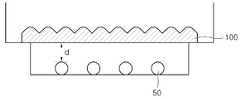
도 1은 본 발명의 바람직한 일 구현예에 의한 광확산 부재(100)가 광원(50)의 상부에 장착된 상태의 종단면도이고, 도 2는 본 발명의 바람직한 일 구현예에 의한 광확산 부재의 종단면도이며, 도 3 내지 도 5는 본 발명의 바람직한 다른 구현예에 의한 광확산 부재의 종단면도이다.1 is a longitudinal cross-sectional view of a
상기 도면들에서는 편의상 동일 구성부분에 대해서는 동일한 부호를 사용하였나, 이들은 조성 및 형태까지 동일한 것을 의미하는 것은 아니다.In the drawings, the same reference numerals are used for the same components for convenience, but they do not mean the same composition and shape.
본 발명의 광확산 부재는 기재층(10)의 일면에 구조층(20)을 포함하고 있다.The light diffusing member of the present invention includes the
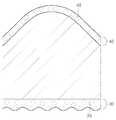
보다 상세하게는 본 발명의 광확산 부재는, 구조층(20)이 다수의 입체 구조를 포함하며, 상기 입체 구조를 종단면으로 보았을 때 피크를 중심으로 좌우 양방향으로 곡률을 갖는 제1구간(2)과, 상기 제1구간(2)의 양측으로 기재층과 경사각을 갖는 제2구간(1)을 포함하는 구조일 수 있다.More specifically, the light diffusing member of the present invention, the
이 때 제2구간(1)은 상기 입체 구조를 종단면으로 보았을 때 기재층(10)을 기준으로 하여 일정 경사각(α)을 갖는 직선으로 이루어지며, 상기 경사각(α)은 30°~50° 또는 130°~150° 인 것일 수 있다.At this time, the second section (1) is made of a straight line having a predetermined inclination angle (α) with respect to the
한편 상기 제1구간(2)의 곡률은 상기 입체 구조를 종단면으로 보아서 피크를 영점으로 하는 x축과 y축을 갖는 좌표로 나타내었을 때, 하기 식 1을 만족하는 것일 수 있다.Meanwhile, the curvature of the
<식 1><

(상기 식에서, x<0 또는 x>0인 정수, y<0 또는 y>0인 정수이고, k는 유리수임.)(In the above formula, x <0 or x> 0 is an integer, y <0 or y> 0 is an integer, and k is a rational number.)
상기 식 1에 따른 곡률 형태를 나타내는 그래프를 도 6에 나타내었다.6 is a graph showing the shape of curvature according to
본 발명의 광확산 부재는 상기 제1구간(2)의 곡률인 상기 식 1의 k값이 0.05~0.30인 것일 수 있다.In the light diffusing member of the present invention, the k value of
본 발명의 광확산 부재는 상기와 같은 곡률을 갖는 제1구간(2)과 제2구간(1)을 포함함으로써, 은폐성에 유리한 것일 수 있다. 이는 입사광이 광확산 부재를 통과하면서 실상(R) 및 적어도 1이상의 허상(V)이 발생될 수 있기 때문이다. 즉, 허상(V)은 빛이 5~15% 정도만 투과되어 작은 피크(peak)를 구현함으로써 생성된 사이드로브(sidelobe)를 말하며, 투과된 빛들이 중첩 현상을 일으켜서 나타나게 된다. 실상(R)과 허상(V)이 발생되는 원리를 도 7에 도시하였다. 이는 종래의 광확산 부 재에서 광확산 입자를 통하여 빛이 확산되는 것(도 8) 보다 효율적이고 확실하게 빛이 세분화될 수 있다.The light diffusing member of the present invention may be advantageous to concealability by including the
따라서 본 발명의 광확산 부재를 통하여 상기 실상 및 적어도 1이상의 허상이 발생될 수 있으며, 이로써 특별히 광확산제를 포함하지 않고도 적절한 은폐성을 제공할 수 있다. 또한 본 발명의 광확산 부재는 전광선투과율이 90% 이상이며, 헤이즈가 90% 이상인 것일 수 있다.Therefore, the real image and at least one virtual image may be generated through the light diffusing member of the present invention, thereby providing appropriate concealment without particularly including a light diffusing agent. In addition, the light diffusing member of the present invention may have a total light transmittance of 90% or more and a haze of 90% or more.
이러한 본 발명의 광확산 부재는 하기 식 2의 웨버분율(Weber Fraction)이 1.0 이하인 것이 차후 화상평가시 안정적인 화상을 제공할 수 있으므로 바람직하다.Such a light diffusing member of the present invention is preferably Weber Fraction of 1.0 or less, because it can provide a stable image for subsequent image evaluation.
<식 2><

(상기 식에서, Lumi.는 루미네센스(Luminescence)임.)(Wherein Lumi. Is Luminescence)
상기 제1구간(2)은 기재층(10)과 접하는 밑변의 길이(a2)가 피치(a)의 1/3~3/5인 것일 수 있는데, 즉, 제1구간(2)의 양측면에 형성되는 제2구간(1) 각각은 기재층(10)과 접하는 밑변의 길이(a1)가 피치(a)의 1/5~1/3인 것이 바람직하다. 기재층(10)과 접하는 밑변의 길이(a2)가 피치(a)의 3/5 을 초과하면 종단면이 반원 형상에 가깝도록 제1구간(2)이 넓어져서 상당부분의 계면이 곡선이므로 빛의 굴절 에 의한 광분리 효과는 증가하고, 제2구간의 빗변에 의하여 허상이 명확히 이분화 되는 광분리 효과는 감소하여 전체적으로 광분리 효과는 감소하게 된다. 또한 기재층(10)과 접하는 밑변의 길이(a2)가 피치(a)의 1/3 미만이면 제1구간(2)이 너무 짧아져 종단면이 삼각형상에 가까워지므로 제2구간의 빗변에 의하여 허상이 명확히 이분화 되는 광분리 현상은 증가하고, 빛의 굴절에 의한 광분리 효과는 감소하여 전체적으로 광분리 효과는 감소하게 된다.The
이 때 구조층(20)의 입체 구조의 피치(a)는 특별히 한정되는 것은 아니나, 100㎛ ~ 500㎛인 것이 바람직하며, 구조층(20)을 구성하는 입체 구조의 높이(b)는 특별히 한정되는 것은 아니나, 25㎛ ~ 300㎛인 것일 수 있는데, 이는 패턴의 형상을 고려하여 최대한의 램프 은폐 효과를 내고 상면에 올라가는 패턴 시트와의 모아레 현상을 없애기 위함이다.At this time, the pitch a of the three-dimensional structure of the
이러한 구조층(20)을 구성하는 입체 구조의 형상은 피크점을 통과하는 수직방향의 중심선을 기준으로 대칭되는 구조인 것이 바람직하나, 이에 한정되는 것은 아니다.The shape of the three-dimensional structure constituting the
이와 같은 본 발명의 광확산 부재(100)는 공압출되어 제조된 것일 수 있다. 즉, 기재층(10) 및 구조층(20)을 구성하는 용융된 베이스 수지가 패턴롤러를 통과하면서 공압출되어 형성된 것일 수 있다. 즉, 각 도면에 도시된 바와 같이 기재층(10) 및 구조층(20)이 층의 구분이 없이 한 종류의 수지로 간단하게 제조될 수 있다. 압출된 광확산 부재의 기재층(10)과 구조층(20)을 포함하는 두께는 0.5~2.0㎜인 것일 수 있다. 압출시 온도는 베이스 수지에 따라 다르나, 200 ~ 300℃에서 압출되는 것이 바람직하다. 이 때 상기 베이스 수지는 폴리카보네이트 수지와 폴리스티렌 수지가 1 : 9 ~ 9 : 1의 중량비율로 혼합된 수지, 폴리카보네이트 수지, 폴리스티렌 수지, 올레핀계 수지, 메틸메타크릴레이트 수지 또는 스티렌-아크릴계 공중합 수지 등을 사용할 수 있다. 이 때 폴리스티렌 수지는 내열성을 갖는 폴리스티렌 수지로서 시차주사열량계, DSC로 측정된 유리전이온도가 110℃ 이상인 것을 사용할 수 있으며, 예컨대 제조사 PS Japan사, 상품명 G9001 등을 사용할 수 있다. 상기 올레핀계 수지로는 사이클로올레핀폴리머(COP) 또는 사이클로올레핀코폴리머(COC)를 포함할 수 있다.Such
한편, 본 발명의 광확산 부재는 기재층(10) 일면에 자외선 경화성 수지 또는 열경화성 수지를 포함하는 조액을 도포 및 경화하여 구조층(20)을 형성한 것일 수도 있다.On the other hand, the light diffusing member of the present invention may be formed by coating and curing a crude liquid containing an ultraviolet curable resin or a thermosetting resin on one surface of the
이 때에는 상기 기재층(10)으로서 폴리에틸렌테레프탈레이트 수지, 폴리메틸메타크릴레이트 수지, 폴리카보네이트 수지, 폴리프로필렌 수지, 폴리에틸렌 수지, 폴리스티렌 수지 또는 스티렌-아크릴계 공중합 수지 등을 사용할 수 있으며, 구조층으로는 경화성 수지로서 광투과성 재료이면 특별히 제한되지 않는다. 즉, 자외선 경화성 수지 혹은 열경화성 수지를 포함하는 고분자 수지이면 제한되지 않고 사용 가능한데, 예를 들면, 불포화 지방산 에스테르, 방향족 비닐 화합물, 불포화 지방 산과 그 유도체, 불포화 이가산(unsaturated dibasic acid)과 그 유도체, 메타크릴로나이트릴과 같은 비닐 시아나이드(cyanide) 화합물 등이 사용될 수 있다. 이 때 기재층(10)과의 굴절률을 고려하여 사용하는 고분자 수지를 조절할 수 있다.In this case, polyethylene terephthalate resin, polymethyl methacrylate resin, polycarbonate resin, polypropylene resin, polyethylene resin, polystyrene resin or styrene-acrylic copolymer resin may be used as the
상기 기재층(10)은 기계적 강도 및 열안정성, 그리고 유연성에 있어서 유리하도록 하고 투과광의 손실을 방지하는 측면에서 두께가 10~1000㎛일 수 있으며, 보다 바람직하게는 15~400㎛이 좋다.The
한편 상기 기재층(10)은 요철을 포함할 수 있는데, 이 경우 광이 입사하는 방향의 면이 요철을 포함하는 것이 은폐성에 유리할 수 있다. 형성방법은 특별히 한정되지 않으며, 광확산 부재를 공압출로 제조시에는 기재층(10)을 형성하는 롤러로서 엠보패턴롤러을 이용하여 형성하는 것일 수 있다. 요철을 포함하는 경우 그 표면조도(Ra)는 2~40㎛인 것일 수 있다.Meanwhile, the
한편, 본 발명의 광확산 부재는 상기 기재층(10)에 광확산성 입자(미도시됨)가 포함될 수 있으며, 입경이 1~50㎛인 것을 사용하는 것이 바람직하고, 상기 바인더 수지 100중량부에 대하여 1~40중량부를 포함하는 것이 좋다. 이와 같은 입경의 광확산성 입자를 상기의 함량으로 포함하는 경우 구조층의 광경로에 영향을 미치지 않으면서 오히려 램프 은폐성을 향상시키는 적절한 광확산 효과를 제공할 수 있으며, 상기 설명한 요철을 형성할 수도 있다.On the other hand, the light diffusing member of the present invention may include light diffusing particles (not shown) in the
상기 광확산성 입자로는 복수 개의 유기입자 또는 무기입자를 사용할 수 있다. 대표적으로 사용되는 유기입자로는 메틸메타크릴레이트, 아크릴산, 메타크릴산, 히드록시에틸메타크릴레이트, 히드록시프로필메타크릴레이트, 아크릴아미드, 메틸올아크릴아미드, 글리시딜메타크릴레이트, 에틸아크릴레이트, 이소부틸아크릴레이트, 노말부틸아크릴레이트 및 2-에틸헥실아크릴레이트 중 선택된 단독 중합체 또는 2종 이상 공중합체의 아크릴계 입자; 폴리에틸렌, 폴리스티렌, 폴리프로필렌 등의 올레핀계 입자; 아크릴계와 올레핀계의 공중합체 입자; 및 단독 중합체의 입자를 형성한 후 그 층위에 다른 종류의 단량체로 덮어 씌워 만든 다층 다성분계 입자, 실록산계 중합체 입자, 테트라플루오로에틸렌계 입자 등을 들 수 있으며, 무기 입자로서는 산화규소, 산화알루미늄, 산화티타늄, 산화지르코늄 및 불화마그네슘 등을 들 수 있다. 상기 유기 및 무기 입자들은 단지 예시적인 것에 불과하며, 상기 나열된 유기 또는 무기 재질의 입자에 한정되지 않고 본 발명의 목적을 달성할 수 있는 한 다른 공지된 재료로 얼마든지 대체할 수 있음은 당업자에게는 자명하며, 이러한 재질 변경의 경우도 역시 본 발명의 기술적 사상의 범주 내이다.As the light diffusing particles, a plurality of organic particles or inorganic particles may be used. Representative organic particles include methyl methacrylate, acrylic acid, methacrylic acid, hydroxyethyl methacrylate, hydroxypropyl methacrylate, acrylamide, methylol acrylamide, glycidyl methacrylate, and ethyl acryl. Acrylic particles of a homopolymer or two or more copolymers selected from latex, isobutyl acrylate, normal butyl acrylate and 2-ethylhexyl acrylate; Olefinic particles such as polyethylene, polystyrene and polypropylene; Acrylic and olefin copolymer particles; And multi-layered multicomponent particles, siloxane polymer particles, tetrafluoroethylene particles, etc. formed by forming particles of a homopolymer and then covering the layers with other types of monomers. Examples of the inorganic particles include silicon oxide and aluminum oxide. , Titanium oxide, zirconium oxide, magnesium fluoride and the like. It will be apparent to those skilled in the art that the organic and inorganic particles are merely exemplary, and are not limited to the particles of the organic or inorganic materials listed above, and may be replaced by other known materials as long as the object of the present invention can be achieved. In addition, such a material change is also within the scope of the technical idea of the present invention.
한편, 도 2 내지 도 5에 도시된 바와 같이, 본 발명의 광확산 부재는 기재층(10)의 일면에만 구조층(20)이 형성되는 경우, 구조층(20)이 형성된 면이 아닌 기재층(10)의 이면에 저면층(30)이 더 형성될 수도 있다.On the other hand, as shown in Figures 2 to 5, in the light diffusion member of the present invention, when the
상기 저면층(30)은 공압출됨으로써 형성될 수도 있고, 고분자 수지를 기재층(10)의 일면에 도포하여 경화시킴으로써 형성될 수도 있다. 이 때 고분자 수지에 입자(35)를 분산시킬 수 있다.The
저면층(30)이 용융된 베이스 수지가 압출되어 구조층을 형성하는 패턴롤러를 통과하면서 공압출되어 형성되는 경우, 압출시 온도는 베이스 수지에 따라 다르나, 200 ~ 300℃에서 압출되는 것이 바람직하다. 이 때 상기 베이스 수지는 폴리카보네이트 수지와 폴리스티렌 수지가 1 : 9 ~ 9 : 1의 중량비율로 혼합된 수지, 폴리카보네이트 수지, 폴리스티렌 수지, 올레핀계 수지, 메틸메타크릴레이트 수지 또는 스티렌-아크릴계 공중합 수지 등을 사용할 수 있다. 이 때 폴리스티렌 수지는 내열성을 갖는 폴리스티렌 수지는 시차주사열량계, DSC로 측정된 유리전이온도가 110℃ 이상인 것일 수 있으며, 예컨대 제조사 PS Japan사 상품명 G9001 등을 사용할 수 있다. 상기 올레핀계 수지로는 사이클로올레핀폴리머(COP) 또는 사이클로올레핀코폴리머(COC)를 포함할 수 있다.When the
한편, 저면층(30)이 경화 형성되는 경우, 바인더 수지는 기재층(10)과 접착성이 좋으며 분산되는 입자(35)들과 상용성이 좋은 수지, 즉 입자(35)가 수지에 골고루 분산되어 분리되거나 침전이 잘 생기지 않는 것을 사용하며, 그 구체적인 예를 들면, 불포화폴리에스테르, 메틸메타크릴레이트, 에틸메타크릴레이트, 이소부틸메타크릴레이트, 노말부틸메타크릴레이트, 노말부틸메틸메타크릴레이트, 아크릴산, 메타크릴산, 히드록시에틸메타크릴레이트, 히드록시프로필메타크릴레이트, 히드록시에틸아크릴레이트, 아크릴아미드, 메틸올아크릴아미드, 글리시딜메타크릴레이트, 에틸아크릴레이트, 이소부틸아크릴레이트, 노말부틸아크릴레이트, 2-에틸헥실아크릴레이트의 단독중합체, 이들의 공중합체 또는 삼원 공중합체 등의 아크릴계 수지와, 우레탄계 수지, 에폭시계 수지, 멜라민계 수지 등을 들 수 있다.On the other hand, when the
한편 저면층(30)은 표면에 요철을 포함하는 것일 수 있다. 형성방법은 특별히 한정되지 않으며, 저면층(30)에 입자(35)를 포함함으로써 요철이 형성될 수도 있으며, 또는 압출 형성시 엠보패턴롤러를 통과하도록하여 요철을 형성할 수도 있다. 요철을 포함하는 경우 그 표면조도(Ra)는 2~40㎛인 것일 수 있다.Meanwhile, the
저면층(30)에 포함되는 입자(35)는 상술한 광확산성 입자로서의 유기입자 또는 무기입자를 사용할 수 있으며, 상기 기재층(10)에 포함될 수 있는 광확산성 입자와 같거나 다른 것일 수 있다.The
상기 저면층(30)은 바인더 수지 또는 베이스 수지 100중량부에 대하여 입자(35)를 1~40중량부 포함하는 것이 바람직한데, 이는 손상방지효과 발현 및 광확산에 유리하고, 광 이용 효율을 감소시키지 않도록 하면서 전방 휘도를 고려한 것이다.The
저면층(30)은 표면에 형성된 돌출부에 의해 부수적으로 램프 가이드 핀과의 접촉 면적을 줄임으로써, 낱장으로의 분리, 이동 또는 조립 과정 및 운송과정 중에 발생할 수 있는 표면의 손상을 방지하는 기능을 할 수 있다. 이러한 저면층(30)의 두께는 특별히 한정되는 것은 아니나, 10~300㎛인 것이 바람직하다.The
또한 도 5에 도시된 바와 같이, 본 발명의 광확산 부재는 구조층(20)의 기재층(10)이 형성된 면이 아닌 다른 일면, 즉, 구조층(20)의 입체구조의 표면 상에 표면층(40)이 더 형성될 수도 있으며, 상기 표면층(40)은 입자(45)를 포함할 수 있다.In addition, as shown in FIG. 5, the light diffusing member of the present invention has a surface layer on one surface other than the surface on which the
표면층(40) 역시 상기 저면층(30)의 형성방법과 동일하게 형성될 수 있으며, 포함되는 입자(45) 역시 상술한 바와 같은 광확산성 입자로서 유기입자 또는 무기입자를 사용할 수 있으며, 상기 기재층(10)에 포함되는 광확산성 입자와 같거나 다 른 것일 수 있다. 상기 표면층(40)은 베이스 수지 또는 바인더 수지 100중량부에 대하여 입자를 1~40중량부 포함하는 것이 바람직한데, 이는 광확산 및 은폐성에 유리하고, 광 이용 효율을 감소시키지 않도록 하면서 전방 휘도를 고려한 것이다. 이러한 표면층(40)의 두께는 특별히 한정되는 것은 아니나, 10~300㎛인 것이 바람직하다.The
이와 같이 본 발명의 광확산 부재는 저면층(30) 및 표면층(40)을 구비하지 않을 수도 있고, 저면층(30) 또는 표면층(40)을 선택적으로 구비할 수도 있으며, 도 5에 도시된 바와 같이, 저면층(30) 및 표면층(40)을 모두 구비할 수도 있다.As such, the light diffusing member of the present invention may not include the
본 발명의 광확산 부재는 일면 또는 양면에 대전방지처리를 할 수 있는데, 예컨대 대전방지제를 포함하거나 대전방지성분을 스프레이 등의 방법으로 코팅할 수 있다.The light diffusing member of the present invention may be subjected to an antistatic treatment on one or both surfaces, for example, may include an antistatic agent or may be coated with an antistatic component by spraying or the like.
한편, 본 발명은 이상 설명한 광확산 부재의 어느 일면에 인접하여 형성된 프리즘 시트를 포함하는 백라이트 유닛 어셈블리를 제공할 수 있다.On the other hand, the present invention can provide a backlight unit assembly including a prism sheet formed adjacent to one surface of the light diffusing member described above.
본 발명의 백라이트 유닛 어셈블리는 광원과 본 발명의 광확산 부재의 거리(d)가 2~10㎜인 것일 수 있으며, 이는 종래 백라이트 유닛 어셈블리에서의 광원과 광확산 부재의 거리가 13~17㎜인 것에 비하여 월등히 줄어든 것이며, 그럼에도 불구하고 종래의 경우와 동등 이상의 은폐성을 제공할 수 있다.In the backlight unit assembly of the present invention, the distance d between the light source and the light diffusing member of the present invention may be 2 to 10 mm, and the distance between the light source and the light diffusing member in the conventional backlight unit assembly is 13 to 17 mm. Compared to the conventional case, it can be provided with much less concealment than the conventional case.
이하, 본 발명을 실시예를 통하여 보다 상세히 설명하나, 본 발명의 범위가 하기 실시예로 한정되는 것은 아니다.Hereinafter, the present invention will be described in more detail with reference to Examples, but the scope of the present invention is not limited to the following Examples.
<실시예 1><Example 1>
폴리스티렌수지 펠렛을 220℃, 1축 스크류 직경 135㎜, 60㎜에서 공압출하였으며, 광확산 부재 전체 두께가 1.5mm이 되게 하였으며, 피치가 300㎛, 높이(b) 130㎛, 경사각(α) 40도, 곡률(k) 0.21, 제2구간(1)의 기재층과 접하는 밑변의 길이(a1) 75㎛, 제1구간(2)의 기재층과 접하는 밑변의 길이(a2) 150㎛이 되도록 패턴롤러를 지나면서 도 2의 도면과 같은 형상의 단위 구조가 일렬로 선형 배열된 구조층(20)이 형성된 광확산 부재를 제조하였다.The polystyrene resin pellets were coextruded at 220 ° C, uniaxial screw diameter 135mm, 60mm, and the total thickness of the light diffusion member was 1.5mm, pitch was 300㎛, height (b) 130㎛, tilt angle (α) 40 Also, the curvature k 0.21, the length of the bottom side (a1 ) in contact with the base layer of the second section1 is 75 μm, and the length (a2 ) 150 μm of the bottom side in contact with the base layer of the
<실시예 2><Example 2>
상기 실시예 1에서, 구조층의 단위 구조 피치가 200㎛, 높이(b) 60㎛, 경사각(α) 43°, 곡률(k) 0.15, 제2구간(1)의 기재층과 접하는 밑변의 길이(a1) 50㎛, 제1구간(2)의 기재층과 접하는 밑변의 길이(a2) 100㎛인 것을 제외하고 동일한 방법으로 광확산 부재를 제조하였다.In Example 1, the unit structure pitch of the structural layer is 200 μm, the height (b) 60 μm, the inclination angle (α) 43 °, the curvature (k) 0.15, the length of the base side in contact with the base layer of the second section (1) (a1 ) A light-diffusion member was manufactured in the same manner except that the thickness (a2 ) of the bottom side in contact with the base layer of the first section2 was 100 μm.
<실시예 3><Example 3>
상기 실시예 1에서, 기재층 및 구조층의 베이스 수지로서 폴리카보네이트 수지 펠렛을 사용한 것을 제외하고, 동일한 방법으로 광확산 부재를 제조하였다.In Example 1, a light diffusing member was manufactured in the same manner except that polycarbonate resin pellets were used as the base resin of the base layer and the structural layer.
<실시예 4><Example 4>
상기 실시예 1에서, 기재층 및 구조층의 베이스 수지를 스티렌-아크릴계 공중합 수지로 한 것을 제외하고, 동일한 방법으로 광확산 부재를 제조하였다.In Example 1, a light diffusing member was manufactured in the same manner except that the base resin of the base layer and the structural layer was made of a styrene-acrylic copolymer resin.
<실시예 5>Example 5
메타크릴레이트 수지를 도 2의 도면과 같은 형상의 단위 구조가 일렬로 선형 배열되도록 몰드에 도포한 후, 폴리에틸렌테레프탈레이트 필름(희성전자, LM170E01)를 라미네이션한 후, 자외선을 120Watt의 세기로 3초간 조사하여 경화시키고, 금속 몰드로부터 이형하여 광확산 부재를 제조하였다. 구조층의 피치가 300㎛, 높이(b) 130㎛, 경사각(α) 40도, 곡률(k) 0.21, 제2구간(1)의 기재층(10)과 접하는 밑변의 길이(a1) 75㎛, 제1구간(2)의 기재층(10)과 접하는 밑변의 길이(a2) 150㎛이었다.After applying the methacrylate resin to the mold so that the unit structure of the shape as shown in Figure 2 linearly arranged in a row, after laminating a polyethylene terephthalate film (heesung electronics, LM170E01), the ultraviolet light is applied for 3 seconds at 120Watt intensity It irradiated and hardened | cured, and it mold-released from the metal mold and produced the light-diffusion member. The pitch of the structural layer is 300 μm, the height (b) 130 μm, the inclination angle (α) 40 degrees, the curvature (k) 0.21, the length of the base side contacting the
<실시예 6><Example 6>
상기 실시예 1에서, 구조층이 형성되지 않은 기재층의 다른 일면에 폴리카보네이트 수지 펠렛을 베이스 수지로 사용하고, 상기 베이스 수지 100중량부에 대하여 입자로서 메틸메타크릴레이트 입자(평균입경 2㎛)를 1.2중량부 포함하는 저면층을 그 두께가 30㎛가 되도록 기재층, 구조층과 함께 공압출하여 광확산 부재를 제조하였다. 상기 저면층의 표면조도(Ra) 값은 10㎛였다.In Example 1, polycarbonate resin pellets are used as the base resin on the other side of the base layer on which the structural layer is not formed, and methyl methacrylate particles (average particle diameter: 2 mu m) as particles with respect to 100 parts by weight of the base resin. Co-extruded together with the base material layer and the structural layer so that the bottom layer containing 1.2 parts by weight of the thickness is 30㎛. The surface roughness (Ra) value of the said bottom layer was 10 micrometers.
<실시예 7><Example 7>
상기 실시예 1에서, 구조층이 형성되지 않은 기재층의 다른 일면에 바인더 수지로서 메틸메타크릴레이트 수지를 사용하고, 상기 바인더 수지 100중량부에 대하여 입자로서 실리콘 수지 입자를 (평균입경 2㎛)를 1.2중량부 혼합하여 저면층의 두께가 30㎛가 되도록 코팅하여 자외선을 120Watt의 세기로 3초간 조사하여 경화시킴으로써 광확산 부재를 제조하였다. 상기 저면층의 표면조도(Ra) 값은 10㎛였다.In Example 1, methyl methacrylate resin is used as the binder resin on the other side of the base layer on which the structural layer is not formed, and silicone resin particles are used as particles with respect to 100 parts by weight of the binder resin (average particle diameter: 2 μm). Was prepared by mixing 1.2 parts by weight of the bottom layer so that the thickness of the bottom layer was 30 μm, and irradiated with ultraviolet rays at a intensity of 120 Watts for 3 seconds to cure the light diffusion member. The surface roughness (Ra) value of the said bottom layer was 10 micrometers.
<비교예 1>Comparative Example 1
상기 실시예 1에서, 구조층이 종단면의 반원형이며, 피치 200㎛, 높이(b) 150㎛인 반구형 구조가 일렬로 선형 배열된 구조를 갖도록 한 것을 제외하고 동일한 방법으로 광확산 부재를 제조하였다.In Example 1, the light-diffusion member was manufactured in the same manner except that the structural layer was a semicircle of a longitudinal section, and a hemispherical structure having a pitch of 200 µm and a height (b) of 150 µm was linearly arranged in a line.
<비교예 2>Comparative Example 2
상기 실시예 1에서, 구조층이 종단면이 삼각형이고, 피치 300㎛, 높이(b) 150㎛, 경사각(α)이 45°인 선형 배열된 삼각 프리즘 구조를 갖도록 한 것을 제외하고 동일한 방법으로 광확산 부재를 제조하였다.In Example 1, the light diffusion was performed in the same manner except that the structural layer had a linearly arranged triangular prism structure having a triangular longitudinal section, a pitch of 300 mu m, a height b of 150 mu m, and an inclination angle α of 45 °. The member was made.
<비교예 3>Comparative Example 3
광확산판 (제조사: 코오롱, 상품명: DP421, 두께: 1.50mm, 투과율: 57.0%, 헤이즈: 99%)을 준비하였다.A light diffusion plate (manufacturer: Kolon, trade name: DP421, thickness: 1.50 mm, transmittance: 57.0%, haze: 99%) was prepared.
<비교예 4><Comparative Example 4>
광확산 시트 (제조사: 코오롱, 상품명: LD613, 두께: 188㎛, 투과율: 75.5%, 헤이즈: 96.0%)에 프리즘 시트(제조사: 코오롱, 상품명: LC213, 두께: 188㎛, 피치: 50㎛, 높이: 25㎛, 경사각 45°)를 준비하였다.Light diffusing sheet (manufacturer: Kolon, brand name: LD613, thickness: 188 μm, transmittance: 75.5%, haze: 96.0%) on the prism sheet (manufacturer: Kolon, brand name: LC213, thickness: 188 μm, pitch: 50 μm, height : 25 µm,
상기 실시예 및 비교예에서 준비된 광확산 부재 등 광학부재에 대하여 다음과 같은 방법으로 물성평가를 실시하였으며, 그 결과는 표 1과 같다.Evaluation of physical properties of optical members, such as the light diffusing members prepared in Examples and Comparative Examples, was carried out in the following manner, and the results are shown in Table 1 below.
(1) 내열성(1) heat resistance
상기 실시예 및 비교예에서의 광확산 부재를 42인치 크기로 절단한 후 길이방향으로 세워서 항온항습기 내부에 고정한 후, 50℃, 80%RH, 500hr 보관 방치하였다. 이때 테스트 전, 후에 광확산 부재의 네 모서리 부분의 들뜸 휨량을 정반에 놓고 Gap Gauge로 측정하고, 네 모서리 휨량의 평균값을 사용하였다. 테스트 전, 후의 휨량 및 휨변화량이 적을수록 내열성이 높다고 할 수 있다.The light diffusing members in the above Examples and Comparative Examples were cut into 42-inch sizes, and then fixed in the thermo-hygrostat after standing in the longitudinal direction. At this time, the lifting bending amount of the four corner portions of the light diffusion member before and after the test was placed on the surface plate and measured by a gap gauge, and the average value of the four corner bending amounts was used. The smaller the amount of warpage and the amount of warpage change before and after the test, the higher the heat resistance.
(2) 웨버분율(은폐성)(2) Weber fraction (hidden)
상기 실시예 및 비교예에서의 광확산 부재를 42인치 액정디스플레이 패널용 백라이트 유닛(LC420WUF)에 장착하고 광원과의 거리를 4.0㎜로 고정하여 휘도대면측정기(MINOLTA사, CA-2000) 휘도(루미네센스)를 측정하였다.The light diffusing member in the above Examples and Comparative Examples was mounted on the 42-inch liquid crystal display panel backlight unit (LC420WUF) and the distance from the light source was fixed at 4.0 mm to determine the luminance face measuring instrument (MINOLTA, CA-2000). Nessence) was measured.
실시예 1에 의한 광확산 부재를 상기 광원 위에 적층한 후 휘도대면측정기(MINOLTA사, CA-2000)로 휘도를 측정하고, 백라이트 유닛 중심값을 기준으로 다음 식 2로 웨버분율을 계산하였으며, 그 결과를 표 1에 나타내었다. 계산된 웨버분율이 작을수록 빛이 균일하게 퍼진 것으로 볼 수 있어 은폐성이 우수한 것이다.After the light diffusing member according to Example 1 was laminated on the light source, luminance was measured with a luminance-facing measuring instrument (MINOLTA, CA-2000), and the webber fraction was calculated by the
<식 2><

상기 식에서, Lumi.는 루미네센스(Luminescence)임.Wherein Lumi. Is Luminescence.
(3) 전광선투과율(3) total light transmittance
상기 실시예 및 비교예에서의 광확산 부재를 6×6㎝인치 크기로 절단한 후, 헤이즈미터 측정기기(NIPPON DENSHOKU사, NDH-2000)로 전광선투과율을 측정하였다.After cutting the light-diffusion member in the said Example and the comparative example to 6x6 cm inch size, total light transmittance was measured with the haze meter measuring apparatus (NIPPON DENSHOKU company, NDH-2000).
이때 샘플은 구조층이 광원면에 위치하고, 구조층이 세로방향으로 위치하게 하여 측정한다. 측정기기는 30min 예열 후에 측정하였다.At this time, the sample is measured with the structural layer on the light source surface and the structural layer on the longitudinal direction. The measuring device was measured after 30 min preheating.
(4) 헤이즈(4) haze
상기 실시예 및 비교예에서의 광확산 부재를 6×6㎝인치 크기로 절단한 후, 헤이즈미터 측정기기(NIPPON DENSHOKU사, NDH-2000)로 헤이즈를 측정하였다.After cutting the light-diffusion member in the said Example and the comparative example to 6x6 cm inch size, haze was measured with the haze meter measuring apparatus (NIPPON DENSHOKU company, NDH-2000).
이때 샘플은 구조층이 광원면에 위치하고, 구조층이 세로방향으로 위치하게 하여 측정한다. 측정기기는 30min 예열 후에 측정한다.At this time, the sample is measured with the structural layer on the light source surface and the structural layer on the longitudinal direction. The measuring device is measured after 30 min preheating.
(5) 휘도(5) luminance
상기 실시예 및 비교예에서의 광확산 부재를 42인치 액정디스플레이 패널용 백라이트 유닛(LC420WUF)에 장착하고 광원과의 거리를 4.0㎜로 고정하여 휘도계(TOPCON사, BM-7)를 사용하여 임의의 13지점의 휘도를 측정하여 그 평균값을 구하였다.The light diffusing member in the above Examples and Comparative Examples was mounted on a 42-inch liquid crystal display panel backlight unit (LC420WUF) and fixed at a distance of 4.0 mm using a luminance meter (TOPCON, BM-7). Luminance was measured at 13 points and the average value was obtained.
(6) 표면조도(Ra)(6) Surface roughness (Ra)
표면조도는 LSM(Laser Scanning Microscopy: CARL ZEISS사, LSM 5 Pascal)으로 측정하였다. 요철의 가장 높은 곳과 가장 낮은 곳을 측정하여 표면조도(Ra) 값을 구하고, 동일 위치에서 3회 반복 측정하여 평균값을 사용하였다.Surface roughness was measured by LSM (Laser Scanning Microscopy: CARL ZEISS, LSM 5 Pascal). The highest and lowest points of the unevenness were measured to obtain a surface roughness (Ra) value, and the average value was used by measuring three times at the same position.
도 1은 본 발명의 바람직한 일 구현예에 의한 광확산 부재가 광원의 상부에 장착된 상태의 종단면도,1 is a longitudinal cross-sectional view of a light diffusing member mounted on an upper portion of a light source according to a preferred embodiment of the present invention;
도 2는 본 발명의 바람직한 일 구현예에 의한 광확산 부재의 종단면도,2 is a longitudinal sectional view of a light diffusing member according to a preferred embodiment of the present invention;
도 3 내지 도 5는 본 발명의 바람직한 다른 구현예에 의한 광확산 부재의 종단면도이다.3 to 5 are longitudinal cross-sectional views of the light diffusing member according to another preferred embodiment of the present invention.
도 6은 본 발명의 바람직한 일 구현예에 의한 광확산 부재의 구조층 제1구간의 곡률 형태를 나타내는 그래프,6 is a graph showing the shape of curvature of the first section of the structural layer of the light diffusing member according to an embodiment of the present invention;
도 7은 본 발명의 바람직한 일 구현예에 의한 광확산 부재를 통하여 실상(R)과 허상(V)이 발생되는 원리를 나타낸 도면,7 is a view showing a principle that the actual image (R) and the virtual image (V) is generated through the light diffusion member according to an embodiment of the present invention,
도 8은 종래 광확산 부재에서 빛이 확산되는 원리를 나타낸 도면이다.8 is a view showing the principle that light is diffused in the conventional light diffusion member.
* 도면의 주요부분의 부호에 대한 설명* Explanation of the symbols of the main parts of the drawings
1 : 제2구간2 : 제1구간1: second section 2: first section
10 : 기재층20 : 구조층10: substrate layer 20: structure layer
30 : 저면층35 : 입자30: bottom layer 35: particles
40 : 표면층45 : 입자40: surface layer 45: particles
50 : 광원 100 : 광확산 부재50
Claims (24)
Translated fromKorean

Priority Applications (5)
| Application Number | Priority Date | Filing Date | Title |
|---|---|---|---|
| KR1020080057756AKR100936063B1 (en) | 2008-06-19 | 2008-06-19 | Light diffusion |
| TW097150522ATWI416202B (en) | 2007-12-24 | 2008-12-24 | Optical member |
| US12/810,262US8556443B2 (en) | 2007-12-24 | 2008-12-24 | Optical member |
| CN200880122705.3ACN101910875B (en) | 2007-12-24 | 2008-12-24 | Optical module |
| PCT/KR2008/007665WO2009082171A2 (en) | 2007-12-24 | 2008-12-24 | Optical member |
Applications Claiming Priority (1)
| Application Number | Priority Date | Filing Date | Title |
|---|---|---|---|
| KR1020080057756AKR100936063B1 (en) | 2008-06-19 | 2008-06-19 | Light diffusion |
Publications (2)
| Publication Number | Publication Date |
|---|---|
| KR20090131816A KR20090131816A (en) | 2009-12-30 |
| KR100936063B1true KR100936063B1 (en) | 2010-01-08 |
Family
ID=41690948
Family Applications (1)
| Application Number | Title | Priority Date | Filing Date |
|---|---|---|---|
| KR1020080057756AExpired - Fee RelatedKR100936063B1 (en) | 2007-12-24 | 2008-06-19 | Light diffusion |
Country Status (1)
| Country | Link |
|---|---|
| KR (1) | KR100936063B1 (en) |
Families Citing this family (1)
| Publication number | Priority date | Publication date | Assignee | Title |
|---|---|---|---|---|
| KR20130079145A (en)* | 2011-12-30 | 2013-07-10 | 코오롱인더스트리 주식회사 | Complex prism sheet |
Citations (4)
| Publication number | Priority date | Publication date | Assignee | Title |
|---|---|---|---|---|
| KR100605430B1 (en)* | 1997-05-09 | 2006-07-28 | 미네소타 마이닝 앤드 매뉴팩춰링 캄파니 | A brightness enhancing article, a brightness enhancing method, and an apparatus comprising the article |
| JP2006259125A (en) | 2005-03-16 | 2006-09-28 | Dainippon Printing Co Ltd | Light converging sheet, surface light source device, transmissive display device |
| KR20070021378A (en)* | 2005-08-18 | 2007-02-23 | 삼성전자주식회사 | Back light assembly and liquid crystal display device having same |
| KR100801591B1 (en)* | 2005-12-30 | 2008-02-11 | 제일모직주식회사 | Light Diffusion Plate for Liquid Crystal Display Backlight Unit |
- 2008
- 2008-06-19KRKR1020080057756Apatent/KR100936063B1/ennot_activeExpired - Fee Related
Patent Citations (4)
| Publication number | Priority date | Publication date | Assignee | Title |
|---|---|---|---|---|
| KR100605430B1 (en)* | 1997-05-09 | 2006-07-28 | 미네소타 마이닝 앤드 매뉴팩춰링 캄파니 | A brightness enhancing article, a brightness enhancing method, and an apparatus comprising the article |
| JP2006259125A (en) | 2005-03-16 | 2006-09-28 | Dainippon Printing Co Ltd | Light converging sheet, surface light source device, transmissive display device |
| KR20070021378A (en)* | 2005-08-18 | 2007-02-23 | 삼성전자주식회사 | Back light assembly and liquid crystal display device having same |
| KR100801591B1 (en)* | 2005-12-30 | 2008-02-11 | 제일모직주식회사 | Light Diffusion Plate for Liquid Crystal Display Backlight Unit |
Also Published As
| Publication number | Publication date |
|---|---|
| KR20090131816A (en) | 2009-12-30 |
Similar Documents
| Publication | Publication Date | Title |
|---|---|---|
| TWI416202B (en) | Optical member | |
| KR20090056903A (en) | Optical Composite Sheet | |
| KR101157298B1 (en) | Optic complex member | |
| KR101087026B1 (en) | Optical Composite Film | |
| KR100909427B1 (en) | Light control film | |
| KR101244550B1 (en) | Light Diffusion member | |
| US20100055409A1 (en) | Optical composite and method of manufacturing the same | |
| KR20110011931A (en) | Condensing optical sheet | |
| KR101087187B1 (en) | Optics | |
| KR100936063B1 (en) | Light diffusion | |
| KR101233533B1 (en) | Backlight Unit Assembly Comprising Light Diffusion member | |
| KR100988764B1 (en) | Optical Composite Film | |
| KR101036357B1 (en) | Light compensation member | |
| KR100980068B1 (en) | Optical Composite Film | |
| KR101067679B1 (en) | Light diffusion | |
| KR101270888B1 (en) | Optic complex member | |
| KR100544518B1 (en) | Prism film with minimal light loss | |
| KR101370167B1 (en) | Backlight unit assembly | |
| KR101353845B1 (en) | Optical sheet having optical pattern layer | |
| KR101182080B1 (en) | Light Diffusion member | |
| KR101155277B1 (en) | Optic complex member | |
| KR100902156B1 (en) | Light control film | |
| WO2008082248A1 (en) | Optical composite and method of manufacturing the same | |
| KR100906984B1 (en) | Backlight unit assembly | |
| KR20100035877A (en) | Optical member |
Legal Events
| Date | Code | Title | Description |
|---|---|---|---|
| PA0109 | Patent application | St.27 status event code:A-0-1-A10-A12-nap-PA0109 | |
| A201 | Request for examination | ||
| A302 | Request for accelerated examination | ||
| PA0201 | Request for examination | St.27 status event code:A-1-2-D10-D11-exm-PA0201 | |
| PA0302 | Request for accelerated examination | St.27 status event code:A-1-2-D10-D17-exm-PA0302 St.27 status event code:A-1-2-D10-D16-exm-PA0302 | |
| D13-X000 | Search requested | St.27 status event code:A-1-2-D10-D13-srh-X000 | |
| D14-X000 | Search report completed | St.27 status event code:A-1-2-D10-D14-srh-X000 | |
| R18-X000 | Changes to party contact information recorded | St.27 status event code:A-3-3-R10-R18-oth-X000 | |
| E902 | Notification of reason for refusal | ||
| PE0902 | Notice of grounds for rejection | St.27 status event code:A-1-2-D10-D21-exm-PE0902 | |
| P11-X000 | Amendment of application requested | St.27 status event code:A-2-2-P10-P11-nap-X000 | |
| P13-X000 | Application amended | St.27 status event code:A-2-2-P10-P13-nap-X000 | |
| E701 | Decision to grant or registration of patent right | ||
| PE0701 | Decision of registration | St.27 status event code:A-1-2-D10-D22-exm-PE0701 | |
| PG1501 | Laying open of application | St.27 status event code:A-1-1-Q10-Q12-nap-PG1501 | |
| GRNT | Written decision to grant | ||
| PR0701 | Registration of establishment | St.27 status event code:A-2-4-F10-F11-exm-PR0701 | |
| PR1002 | Payment of registration fee | St.27 status event code:A-2-2-U10-U11-oth-PR1002 Fee payment year number:1 | |
| PG1601 | Publication of registration | St.27 status event code:A-4-4-Q10-Q13-nap-PG1601 | |
| PN2301 | Change of applicant | St.27 status event code:A-5-5-R10-R13-asn-PN2301 St.27 status event code:A-5-5-R10-R11-asn-PN2301 | |
| PN2301 | Change of applicant | St.27 status event code:A-5-5-R10-R11-asn-PN2301 | |
| PN2301 | Change of applicant | St.27 status event code:A-5-5-R10-R11-asn-PN2301 | |
| PN2301 | Change of applicant | St.27 status event code:A-5-5-R10-R11-asn-PN2301 | |
| PN2301 | Change of applicant | St.27 status event code:A-5-5-R10-R14-asn-PN2301 | |
| FPAY | Annual fee payment | Payment date:20120912 Year of fee payment:4 | |
| PR1001 | Payment of annual fee | St.27 status event code:A-4-4-U10-U11-oth-PR1001 Fee payment year number:4 | |
| R18-X000 | Changes to party contact information recorded | St.27 status event code:A-5-5-R10-R18-oth-X000 | |
| FPAY | Annual fee payment | Payment date:20131122 Year of fee payment:5 | |
| PR1001 | Payment of annual fee | St.27 status event code:A-4-4-U10-U11-oth-PR1001 Fee payment year number:5 | |
| R18-X000 | Changes to party contact information recorded | St.27 status event code:A-5-5-R10-R18-oth-X000 | |
| FPAY | Annual fee payment | Payment date:20141201 Year of fee payment:6 | |
| PR1001 | Payment of annual fee | St.27 status event code:A-4-4-U10-U11-oth-PR1001 Fee payment year number:6 | |
| FPAY | Annual fee payment | Payment date:20151116 Year of fee payment:7 | |
| PR1001 | Payment of annual fee | St.27 status event code:A-4-4-U10-U11-oth-PR1001 Fee payment year number:7 | |
| R18-X000 | Changes to party contact information recorded | St.27 status event code:A-5-5-R10-R18-oth-X000 | |
| P22-X000 | Classification modified | St.27 status event code:A-4-4-P10-P22-nap-X000 | |
| R18-X000 | Changes to party contact information recorded | St.27 status event code:A-5-5-R10-R18-oth-X000 | |
| PR1001 | Payment of annual fee | St.27 status event code:A-4-4-U10-U11-oth-PR1001 Fee payment year number:8 | |
| FPAY | Annual fee payment | Payment date:20171201 Year of fee payment:9 | |
| PR1001 | Payment of annual fee | St.27 status event code:A-4-4-U10-U11-oth-PR1001 Fee payment year number:9 | |
| R18-X000 | Changes to party contact information recorded | St.27 status event code:A-5-5-R10-R18-oth-X000 | |
| FPAY | Annual fee payment | Payment date:20181203 Year of fee payment:10 | |
| PR1001 | Payment of annual fee | St.27 status event code:A-4-4-U10-U11-oth-PR1001 Fee payment year number:10 | |
| PC1903 | Unpaid annual fee | St.27 status event code:A-4-4-U10-U13-oth-PC1903 Not in force date:20200101 Payment event data comment text:Termination Category : DEFAULT_OF_REGISTRATION_FEE | |
| PC1903 | Unpaid annual fee | St.27 status event code:N-4-6-H10-H13-oth-PC1903 Ip right cessation event data comment text:Termination Category : DEFAULT_OF_REGISTRATION_FEE Not in force date:20200101 |