KR100935243B1 - A flexible rod - Google Patents
A flexible rodDownload PDFInfo
- Publication number
- KR100935243B1 KR100935243B1KR1020090048068AKR20090048068AKR100935243B1KR 100935243 B1KR100935243 B1KR 100935243B1KR 1020090048068 AKR1020090048068 AKR 1020090048068AKR 20090048068 AKR20090048068 AKR 20090048068AKR 100935243 B1KR100935243 B1KR 100935243B1
- Authority
- KR
- South Korea
- Prior art keywords
- rod
- socket
- wire
- opening
- cylindrical shape
- Prior art date
- Legal status (The legal status is an assumption and is not a legal conclusion. Google has not performed a legal analysis and makes no representation as to the accuracy of the status listed.)
- Expired - Fee Related
Links
Images


Classifications
- A—HUMAN NECESSITIES
- A61—MEDICAL OR VETERINARY SCIENCE; HYGIENE
- A61B—DIAGNOSIS; SURGERY; IDENTIFICATION
- A61B17/00—Surgical instruments, devices or methods
- A61B17/56—Surgical instruments or methods for treatment of bones or joints; Devices specially adapted therefor
- A61B17/58—Surgical instruments or methods for treatment of bones or joints; Devices specially adapted therefor for osteosynthesis, e.g. bone plates, screws or setting implements
- A61B17/68—Internal fixation devices, including fasteners and spinal fixators, even if a part thereof projects from the skin
- A61B17/70—Spinal positioners or stabilisers, e.g. stabilisers comprising fluid filler in an implant
- A61B17/7001—Screws or hooks combined with longitudinal elements which do not contact vertebrae
- A61B17/7002—Longitudinal elements, e.g. rods
- A61B17/7019—Longitudinal elements having flexible parts, or parts connected together, such that after implantation the elements can move relative to each other
- A61B17/7022—Tethers, i.e. longitudinal elements capable of transmitting tension only, e.g. straps, sutures or cables
- A—HUMAN NECESSITIES
- A61—MEDICAL OR VETERINARY SCIENCE; HYGIENE
- A61B—DIAGNOSIS; SURGERY; IDENTIFICATION
- A61B17/00—Surgical instruments, devices or methods
- A61B17/56—Surgical instruments or methods for treatment of bones or joints; Devices specially adapted therefor
- A61B17/58—Surgical instruments or methods for treatment of bones or joints; Devices specially adapted therefor for osteosynthesis, e.g. bone plates, screws or setting implements
- A61B17/68—Internal fixation devices, including fasteners and spinal fixators, even if a part thereof projects from the skin
- A61B17/70—Spinal positioners or stabilisers, e.g. stabilisers comprising fluid filler in an implant
- A61B17/7001—Screws or hooks combined with longitudinal elements which do not contact vertebrae
- A61B17/7002—Longitudinal elements, e.g. rods
- A61B17/7019—Longitudinal elements having flexible parts, or parts connected together, such that after implantation the elements can move relative to each other
- A61B17/702—Longitudinal elements having flexible parts, or parts connected together, such that after implantation the elements can move relative to each other having a core or insert, and a sleeve, whereby a screw or hook can move along the core or in the sleeve
Landscapes
- Health & Medical Sciences (AREA)
- Orthopedic Medicine & Surgery (AREA)
- Life Sciences & Earth Sciences (AREA)
- Neurology (AREA)
- Surgery (AREA)
- Heart & Thoracic Surgery (AREA)
- Engineering & Computer Science (AREA)
- Biomedical Technology (AREA)
- Nuclear Medicine, Radiotherapy & Molecular Imaging (AREA)
- Medical Informatics (AREA)
- Molecular Biology (AREA)
- Animal Behavior & Ethology (AREA)
- General Health & Medical Sciences (AREA)
- Public Health (AREA)
- Veterinary Medicine (AREA)
- Surgical Instruments (AREA)
Abstract
Description
Translated fromKorean본 발명은 탄성 조절 로드에 관한 것으로서, 더욱 상세하게는 한 쌍의 로드 내부에 탄성을 갖는 와이어를 개재하여 나사 한 상태로 나사 결합된 한 쌍의 로드를 구성하되, 환자의 신체 조건에 따라 나사 결합을 조절하여 로드의 탄성을 조절할 수 있도록 구성함으로써 척추수술 후 인체의 움직임에 따라 척추가 미세하게 움직일 수 있도록 유동성을 확보해주는 탄성 조절 로드에 관한 것이다.The present invention relates to an elastic control rod, and more particularly, a pair of rods screwed in a state of being screwed through a wire having elasticity inside the pair of rods, but screwed according to the physical condition of the patient By adjusting to adjust the elasticity of the rod by adjusting the elastic control rod to ensure the fluidity so that the spine can move finely according to the movement of the human body after spinal surgery.
일반적으로 척추는 통상 24개(천추골제외)의 뼈로 이루어져 각각의 뼈 사이에는 디스크라 불리는 관절에 의해 연결되어 척추를 지지하며 완충작용을 할 수 있게 구성되어 있다. 이를 통하여 척추는 인간의 자세를 유지할 수 있게 도와줄 뿐만 아니라, 운동의 토대가 되며 내장 기관을 보호하는 중요한 역할을 하고 있다.In general, the spine is usually composed of 24 bones (except sacral bone) is connected between each bone by a joint called a disc is configured to support and buffer the spine. Through this, the spine not only helps maintain the human posture, but also serves as the basis for exercise and protects the internal organs.
척추와 관련된 질환의 치료에 있어서 통상적으로 물리치료를 통한 간접적인 치료방법과 손상된 척추경에 별도의 고정장치를 장착하여 척추를 교정 및 고정하는 직접적인 치료방식이 시행된다. 척추 질환이 경미한 경우에는 물리치료를 하게 되나, 척추를 구성하고 있는 경추, 흉추, 요추, 천골 및 추간원판 등에 질환이 심한 경우에는 별도의 척추 고정장치를 이용한 치료가 시행되게 된다.In the treatment of diseases related to the spine, an indirect treatment method through physical therapy and a direct treatment method for correcting and fixing the spine are performed by attaching a separate fixing device to the damaged pedicle. If the spinal disease is mild physical therapy, but if the disease is severe, such as cervical spine, thoracic spine, lumbar spine, sacrum and intervertebral disc constituting the spine will be treated using a separate spinal fixing device.
이러한 직접적 치료방식으로서의 척추 고정(spinal fixation) 시술방법에 사용되는 척추 고정장치는, 손상된 척추부를 정상적인 상태로 교정한 후 움직임 없이 고정할 수 있도록 척추골의 척추경 또는 천골에 소정의 강도와 깊이로 삽입되는 척추 고정 나사와 척추부의 일측에 위치되는 통상 척추 로드로 일컬어지는 로드(rod) 또는 플레이트(plate) 및 상기한 로드 또는 플레이트와 척추 고정 나사를 연계하여 체결하는 체결수단 등으로 구성되어 있으며, 상기 척추 고정장치에 사용되는 척추 로드는 척추를 안정적으로 유지해주고, 비정상적인 움직임(abnormal movement)을 억제하여 불안정성으로 인하여 환자에게 발생하는 통증을 방지하고, 수술시 감압으로 약해진 척추를 보강하기 위하여 사용된다.The spinal fixation device used in the spinal fixation method as a direct treatment method is inserted into the pedicle or sacrum of the vertebra at a predetermined strength and depth so as to fix the damaged vertebrae in a normal state without moving. It is composed of a rod (plate) or plate (plate), usually referred to as a spinal rod which is located on one side of the spinal fixation screw and the spine and the fastening means for coupling the rod or plate and the spinal fixation screw, The spinal rod used in the spinal fixation device is used to keep the spine stable, to suppress abnormal movements, to prevent pain caused by instability, and to reinforce the weakened spine due to decompression during surgery.
그러나, 이와 같은 종래의 척추 로드는 대부분이 의료용 티탄늄 재질로 형성되어 있기 때문에, 로드 자체의 탄성이 없어 이로 인하여 척추 고정 시술후, 로드의 모양대로 척추뼈 마디가 융합(fusion)된 후에는 정상적인 허리 곡선을 유지하기가 힘들고, 척추 간의 움직임을 허용하지 않으므로 장기간 사용할 경우 환자의 정상적인 움직임이 없어지며 상·하 척추관절에 이상이 오는 정션 증후군(junction syndrome) 또는 트랜지션널 증후군(transitional syndrome) 등의 부작용이 나타나는 문제점이 있다.However, since most of the conventional spinal rods are formed of medical titanium, there is no elasticity of the rods themselves. Thus, after spinal fixation, the spinal rods are fused in the shape of the rods. It is difficult to maintain the waist curve and does not allow the movement between the spine, so long-term use will cause the patient to lose his or her normal movement and cause abnormalities in the upper and lower vertebral joints, such as junction syndrome or transitional syndrome. There is a problem that side effects appear.
이러한 문제점을 해결하기 위하여, 척추 로드의 소정 위치에 곡선부를 형성하거나, 또는 유연한 재질이나 구조를 개재하여 탄성을 부여하는 방법이 사용되고 있기는 하지만, 척추 로드의 탄성은 일률적으로 부여되어 환자의 신체 조건에 따라 조절할 수 없고 이에 따라 각각의 단품을 규격화하여 다양한 형상으로 형성해야 하 기 때문에 제작 비용을 증가시키는 요인으로 작용하고 있다.In order to solve this problem, although a method of forming a curved portion at a predetermined position of the spinal rod or providing elasticity through a flexible material or structure is used, elasticity of the spinal rod is uniformly applied to the physical condition of the patient. It can not be adjusted according to this, and accordingly it is acting as a factor to increase the production cost because each single product must be standardized and formed in various shapes.
따라서, 본 발명은 상기한 문제점을 해결하기 위하여, 한 쌍의 로드 내부에 다수 개의 금속사를 꼬아 형성된 와이어를 개재하고 나사 결합을 통해 서로 연결한 후 환자의 신체 조건에 따라 나사 결합을 조절하여 로드의 탄성을 조절함으로써 다양한 탄성을 갖는 로드를 제작하는 일 없이 최적의 탄성을 갖는 로드를 구현할 수 있어 환자의 움직임에 따른 척추뼈의 움직임을 최적화할 수 있는 탄성 조절 로드를 제공하는데 그 목적이 있다.Accordingly, the present invention to solve the above problems, through the wire formed by twisting a plurality of metal yarns inside a pair of rods and connected to each other through screw coupling, and then adjusting the screw coupling according to the physical condition of the patient rod The purpose of the present invention is to provide an elastic rod capable of optimizing the movement of the vertebrae according to the movement of the patient because the rod having the optimum elasticity can be realized without adjusting the elasticity of the rod.
본 발명에 따른 탄성 조절 로드는, 일측에 개구부가 구비된 중공의 원통형으로 형성된 제1로드와; 다수 개의 금속사를 꼬아서 형성되어, 일측이 상기 제1로드의 개구부를 통해 삽입되어 고정되는 와이어와; 상기 와이어의 타측을 삽입시켜 고정시키며, 외경을 따라 수나사산이 형성되어 있는 소켓; 및 상기 소켓을 삽입시킬 수 있도록 일측에 개구부가 형성된 중공의 원통형으로 형성되며, 내부에 상기 수나사산과 맞물려질 수 있도록 내경을 따라 암나사산이 형성되어 있는 제2로드;를 포함하여 구성되되, 상기 소켓과 상기 제2로드의 결합 위치에 따라 노출되는 와이어의 길이를 조절함으로써 로드의 탄성을 조절할 수 있도록 구성되는 것을 특징으로 한다.Elastic adjustment rod according to the present invention, the first rod formed in a hollow cylindrical shape having an opening on one side; A wire formed by twisting a plurality of metal yarns, one side of which is inserted and fixed through the opening of the first rod; A socket to which the other side of the wire is inserted and fixed, and a male thread is formed along an outer diameter; And a second rod formed in a hollow cylindrical shape having an opening formed at one side to insert the socket, and having a female thread formed along an inner diameter so as to be engaged with the male thread therein. It is characterized in that it is configured to adjust the elasticity of the rod by adjusting the length of the exposed wire according to the coupling position of the second rod.
본 발명에 따른 탄성 조절 로드는, 일측에 개구부가 구비된 중공의 원통형으로 형성된 제1로드와; 다수 개의 금속사를 꼬아서 형성되어, 일측이 상기 제1로드 의 개구부를 통해 삽입되어 고정되는 와이어와; 상기 와이어의 외경을 따라 구비되는 중공의 원통형으로 형성된 탄성부재와와; 상기 와이어의 타측을 삽입시키며, 외경을 따라 수나사산이 형성되어 있는 소켓; 및 상기 소켓을 삽입시킬 수 있도록 일측에 개구부가 형성된 중공의 원통형으로 형성되며, 내부에 상기 수나사산과 맞물려질 수 있도록 내경을 따라 암나사산이 형성되어 있는 제2로드;를 포함하여 구성되되, 상기 소켓과 상기 제2로드의 결합 위치에 따라 상기 탄성부재의 수축 정도를 조절함으로써 로드의 탄성을 조절할 수 있도록 구성되는 것을 특징으로 한다.Elastic adjustment rod according to the present invention, the first rod formed in a hollow cylindrical shape having an opening on one side; A wire formed by twisting a plurality of metal yarns, one side of which is inserted and fixed through an opening of the first rod; An elastic member formed in a hollow cylindrical shape provided along the outer diameter of the wire; A socket in which the other side of the wire is inserted and a male thread is formed along an outer diameter; And a second rod formed in a hollow cylindrical shape having an opening formed at one side to insert the socket, and having a female thread formed along an inner diameter so as to be engaged with the male thread therein. And the elasticity of the rod by adjusting the contraction degree of the elastic member according to the coupling position of the second rod.
본 발명에 따른 탄성 조절 로드는, 일측에 개구부가 구비된 중공의 원통형으로 형성된 제1로드와; 다수 개의 금속사를 꼬아서 형성되어, 일측이 상기 제1로드의 개구부를 통해 삽입되어 고정되는 와이어와; 상기 와이어의 타측을 삽입시켜 고정시키며, 외경을 따라 수나사산이 형성되어 있는 소켓; 및 상기 소켓을 삽입시킬 수 있도록 일측에 개구부가 형성된 중공의 원통형으로 형성되며, 내부에 상기 수나사산과 맞물려질 수 있도록 내경을 따라 암나사산이 형성되어 있는 제2로드;를 포함하여 구성되되, 상기 제1로드와 상기 제2로드의 접촉면에는 서로 대응되는 곡면이 형성되어 상기 소켓과 상기 제2로드의 결합 위치에 따라 회동 가능하도록 구성된 것을 특징으로 한다.Elastic adjustment rod according to the present invention, the first rod formed in a hollow cylindrical shape having an opening on one side; A wire formed by twisting a plurality of metal yarns, one side of which is inserted and fixed through the opening of the first rod; A socket to which the other side of the wire is inserted and fixed, and a male thread is formed along an outer diameter; And a second rod formed in a hollow cylindrical shape having an opening formed at one side to insert the socket, and having a female thread formed along an inner diameter so as to be engaged with the male thread therein. A curved surface corresponding to each other is formed on a contact surface of the first rod and the second rod, and is configured to be rotatable according to a coupling position of the socket and the second rod.
본 발명에 따른 탄성 조절 로드는, 일측에 개구부가 구비된 중공의 원통형으로 형성된 제1로드와; 다수 개의 금속사를 꼬아서 형성되어, 일측이 상기 제1로드의 개구부를 통해 삽입되어 고정되는 와이어와; 상기 와이어의 타측을 삽입시켜 고정시키며, 외경을 따라 수나사산이 형성되어 있는 소켓과; 상기 와이어의 외경을 따라 구비되는 중공의 삽입체와; 상기 소켓을 삽입시킬 수 있도록 일측에 개구부가 형성된 중공의 원통형으로 형성되며, 내부에 상기 수나사산과 맞물려질 수 있도록 내경을 따라 암나사산이 형성되어 있는 제2로드;를 포함하여 구성되되, 상기 제1로드의 개구부와 상기 제2로드의 개구부에는 각각 곡면이 형성되고, 상기 삽입체에는 상기 제1로드의 개구부 및 상기 제2로드의 개구부에 각각 형성된 곡면과 서로 맞물려질 수 있도록 곡면이 형성되어, 상기 소켓과 상기 제2로드의 결합 위치에 따라 상기 제1로드와 상기 제2로드 및 상기 삽입체가 회동 가능하도록 구성된 것을 특징으로 한다.Elastic adjustment rod according to the present invention, the first rod formed in a hollow cylindrical shape having an opening on one side; A wire formed by twisting a plurality of metal yarns, one side of which is inserted and fixed through the opening of the first rod; A socket formed by inserting and fixing the other side of the wire and having a male thread formed along an outer diameter thereof; A hollow insert provided along an outer diameter of the wire; And a second rod formed in a hollow cylindrical shape having an opening formed at one side to insert the socket, and having a female thread formed along an inner diameter to be engaged with the male thread therein. A curved surface is formed in each of the opening of the rod and the opening of the second rod, and the curved surface is formed in the insert so as to be engaged with the curved surfaces respectively formed in the opening of the first rod and the opening of the second rod, The first rod, the second rod and the insert can be rotatable according to the coupling position of the socket and the second rod.
본 발명에 따른 탄성 조절 로드에 의하면, 한 쌍의 로드를 내부에 탄성을 갖는 와이어를 개재한 상태로 나사 결합을 통해 연결하고, 환자의 신체적 조건에 따라 나사 결합 강도를 조절하여 와이어를 통해 로드의 탄성을 조절함으로써 환자의 신체적 조건에 따라 로드의 탄성을 조절할 수 있어 인체의 움직임에 따라 척추 뼈 마디 사이에 미세한 유동성을 부여하여 또 다른 척추 질환이 유발되는 것을 방지할 수 있는 동시에 다양한 탄성을 갖는 로드를 제작할 필요가 없으므로 로드 제작에 소요되는 비용을 절감할 수 있다는 효과가 있다.According to the elastic adjustment rod according to the present invention, a pair of rods are connected through screwing while interposing elastic wires therein, and the screw coupling strength is adjusted according to the physical condition of the patient to allow the rod to be connected. By adjusting the elasticity, the elasticity of the rod can be adjusted according to the physical condition of the patient, thereby providing minute fluidity between the spinal bone nodes according to the movement of the human body to prevent another spinal disease from occurring and at the same time, the rod having various elasticities Since there is no need to produce a, there is an effect that can reduce the cost of manufacturing the rod.
이하, 본 발명의 실시예에 대하여 상세히 설명하지만, 본 발명은 그 요지를 이탈하지 않는 한 이하의 실시예에 한정되지 않는다.EMBODIMENT OF THE INVENTION Hereinafter, although the Example of this invention is described in detail, this invention is not limited to a following example, unless the summary is exceeded.
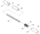
도 1은 본 발명의 제1실시예에 따른 탄성 조절 로드의 구성을 보여주는 분해사시도이고, 도 2는 도 1에 도시된 탄성 조절 로드의 결합 상태를 보여주는 단면도이고, 도 3은 본 발명의 제1실시예에 따른 탄성 조절 로드의 유동 상태를 보여주는 도면이다.1 is an exploded perspective view showing the configuration of the elastic control rod according to the first embodiment of the present invention, Figure 2 is a cross-sectional view showing a coupling state of the elastic control rod shown in Figure 1, Figure 3 is a first of the present invention Figure showing the flow state of the elastic control rod according to the embodiment.
도 1을 참조하면, 본 발명의 제1실시예에 따른 탄성 조절 로드는, 일측에 개구부(112)가 구비된 중공의 원통형으로 형성된 제1로드(110)와, 다수 개의 금속사를 꼬아서 형성되어 일측이 제1로드(110)의 개구부(112)를 통해 삽입되어 고정되는 와이어(130)와, 몸체를 관통하는 관통구(142)가 형성된 중공의 원통형으로 형성되어 와이어(130)의 타측을 삽입시켜 고정시키며 외경을 따라 수나사산(144)이 형성되어 있는 소켓(140) 및 소켓(140)을 삽입시킬 수 있도록 일측에 개구부(122)가 형성된 중공의 원통형으로 형성되며, 내부에 수나사산(144)과 맞물려질 수 있도록 내경을 따라 암나사산(124)이 형성되어 있는 제2로드(120)를 포함하여 구성되며, 소켓(140)과 제2로드(120)의 결합 위치에 따라 노출되는 와이어(130)의 길이를 조절함으로써 로드의 탄성을 조절할 수 있도록 구성된다.Referring to Figure 1, the elastic control rod according to the first embodiment of the present invention, the
제1로드(110) 및 제2로드(120)는 척추로 가해지는 하중을 견딜 수 있고, 인체에 삽입되어 인체와 화학적 반응 및 부작용을 발생시키지 않는 생체 친화성 재질로 이루어지며, 바람직하게는 스테인레스 스틸, 티타늄 또는 티타늄 합금 등을 이용하여 형성될 수 있다. 또한, 제1로드(110)의 일측에는 몸체의 너비방향으로 관통하며 소정 크기의 관통구(114)가 형성되어 있으며, 관통구(114)는 제1로드(110) 내부에 삽입되는 와이어(130)를 용접하여 고정시키기 위해 형성된 것이다.The
와이어(130)도 제1로드(110) 및 제2로드(120)와 같이, 인체에 삽입되어 인체와 화학적 반응 및 부작용을 발생시키지 않는 생체 친화성 재질로 이루어질 수 있으며, 바람직하게는 스테인레스 스틸, 티타늄 또는 티타늄 합금 등을 이용하여 형성될 수 있다.Like the
또한, 도 1에 도시된 바와 같이, 와이어(130)는 다수 개의 금속사를 꼬아서 형성된 것으로, 금속사의 가닥수를 증가시킬수록 강도는 증가하게 되지만, 척추에 가해지는 하중에 따라 휘는 정도가 감소하게 된다. 따라서, 본 발명에서는 7가닥의 금속사를 꼬아서 하나의 금속사 집합을 형성하고, 다시 7개의 금속사 집합을 다시 꼬아서 와이어를 형성하여 척추에 가해지는 하중을 견딜 수 있게 하는 동시에 하중에 따라 어느 정도 휠 수 있도록 구성하였다.In addition, as shown in Figure 1, the
와이어(130)의 일측은 제1로드(110)의 개구부(112)를 통해 제1로드(110) 내부로 삽입된 후 관통구(114)를 통해 용접함으로써 고정시킬 수 있고, 와이어(130)의 일측 및 제1로드(110)의 내부에 접착제를 도포한 후 고정시킬 수도 있다. 또한, 와이어(130)의 타측도 소켓(140)의 관통구(142)에 삽입된 후 접착제 또는 용접을 통해 고정시킬 수 있다.One side of the
소켓(140)은 중공의 원통형으로 형성되며, 외경을 따라 수나사산(144)이 형성되어 있다. 소켓(140)도 제1로드(110) 및 제2로드(120)와 마찬가지로 인체에 삽입되어 인체와 화학적 반응 및 부작용을 발생시키지 않는 생체 친화성 재질로 이루어질 수 있으며, 바람직하게는 스테인레스 스틸, 티타늄 또는 티타늄 합금 등을 이용하여 형성될 수 있다.The
제2로드(120)는 일측에 개구부(122)가 형성된 중공의 원통형으로 형성되고, 내경을 따라 소켓(140)의 수나사산(144)과 맞물려져 회전할 수 있도록 암나사산(124)이 형성되어 있다.The
이러한 구성으로 이루어지는 탄성 조절 로드는 제2로드(120)와 소켓(140)의 나사 결합을 통해 로드의 탄성을 조절할 수 있으며, 이는 제2로드(120)를 회전시켜 제1로드(110)로부터 이격시켜 제1로드(110)와 제2로드(120) 사이에 노출되는 와이어(130)의 길이를 조절함으로써 수행될 수 있다.The elastic adjustment rod made of this configuration can adjust the elasticity of the rod through the screw coupling of the
보다 상세하게 살펴보면, 도 3에 도시된 바와 같이 제1로드(110)와 제2로드(120)가 밀착된 상태에서 제2로드(120)를 회전시켜 제2로드(120)가 소켓(140)의 외경을 따라 형성된 수나사산(144)을 따라 이동하여 제1로드(110)로부터 이격되고, 이로 인해 제2로드(120) 내부에 삽입되어 있던 와이어(130)가 노출된다. 따라서 이러한 상태에서 탄성 조절 로드를 척추뼈에 고정하면 척추에 가해지는 하중에 의해 제1로드(110)와 제2로드(120)가 와이어(130)를 통해 미세하게 유동하게 된다. 이때, 제1로드(110)와 제2로드(120) 사이에 노출되는 와이어(130)의 길이가 길어질수록 휘는 정도가 증가하며, 이는 환자의 신체 조건, 예를 들어 체중에 따라 조절될 수 있다.In more detail, as shown in FIG. 3, the
도 4는 본 발명의 제2실시예에 따른 탄성 조절 로드의 구성을 보여주는 분해사시도이고, 도 5는 본 발명의 제2실시예에 따른 탄성 조절 로드를 구성하는 탄성부재의 다른 형태를 보여주는 정면도이며, 도 6은 도 4에 도시된 탄성 조절 로드의 결합 상태를 보여주는 단면도이다.Figure 4 is an exploded perspective view showing the configuration of the elastic control rod according to the second embodiment of the present invention, Figure 5 is a front view showing another form of the elastic member constituting the elastic control rod according to the second embodiment of the present invention. 6 is a cross-sectional view illustrating a coupling state of the elastic control rod illustrated in FIG. 4.
도 4 및 도 6을 참조하면, 본 발명의 제2실시예에 따른 탄성 조절 로드는, 일측에 개구부(212)가 형성된 중공의 원통형 제1로드(210)와, 다수 개의 금속사를 꼬아서 형성되어 일측이 제1로드(210)의 개구부(212)를 통해 삽입·고정되는 와이어(230)와, 와이어(230)의 외경을 따라 구비되는 중공의 원통형으로 형성된 탄성부재(250)의 타측을 삽입시키며, 외경을 따라 수나사산(244)이 형성되어 있는 소켓(240) 및 소켓(240)을 삽입시킬 수 있도록 일측이 개방된 중공의 원통형으로 형성되며 내부에 소켓(240)의 수나사산(244)과 맞물려질 수 있도록 내경을 따라 암나사산(224)이 형성되어 있는 제2로드(220)를 포함하여 구성되며, 소켓(240)과 제2로드(220)의 결합 위치에 따라 탄성부재(250)의 수축 정도를 조절함으로써 탄성을 조절할 수 있도록 구성된다.4 and 6, the elastic adjustment rod according to the second embodiment of the present invention is formed by twisting a plurality of metal yarns with a hollow cylindrical
본 발명의 제2실시예에 따른 탄성 조절 로드는, 상술한 제1실시예에 따른 탄성 조절 로드와는 제1로드(210)와 제2로드(220) 사이에 탄성부재(250)가 개재되는 점이 상이하며, 나머지 구성요소는 동일하다.In the elastic adjustment rod according to the second embodiment of the present invention, an
탄성부재(250)는 인체와 화학적 반응 및 부작용을 유발시키지 않으며, 탄성을 갖는 폴리우레탄(PU), 폴리카보네이트-우레탄(PCU) 또는 실리콘을 포함하는 폴리머가 사용될 수 있다.The
또한, 탄성부재(250)는 도 5에 도시된 바와 같이 중공의 원통형으로 형성되는데, 경우에 따라서는 탄성부재(250)의 표면에 외경을 따라 다수 개의 요홈부를 일정한 간격으로 형성(a)하거나, 또는 다수 개의 절개부를 일정한 간격으로 형 성(b)함으로써 제1로드(210)와 제2로드(220) 사이에서 수축과 이완을 가능하게 하는 동시에 와이어(230)에 형성되는 홈을 따라 생체가 부착되는 것을 방지한다.In addition, the
즉, 탄성부재(250)는 소정의 탄성을 갖는 재질로 형성되기 때문에 제1로드(210)와 제2로드(220) 사이에서 수축된 상태로 개재되는 경우 강도가 증가하게 되고, 제2로드(220)를 회전시켜 제1로드(210)으로부터 이격시키는 경우에는 도 6에 도시된 바와 같이 탄성부재(250)는 제1로드(210)와 제2로드(220)에 의해 지지됨과 동시에 제1로드(210)와 제2로드(220) 방향으로 이완되기 때문에 탄성부재(250)의 자체 강도가 감소하여 하중이 가해면 휘게 된다.That is, since the
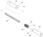
도 7은 본 발명의 제3실시예에 따른 탄성 조절 로드의 구성을 보여주는 분해사시도이고, 도 8은 도 7에 도시된 탄성 조절 로드의 결합 상태를 보여주는 단면도이며, 도 9는 본 발명의 제3실시예에 따른 탄성 조절 로드의 유동 상태를 보여주는 도면이다.7 is an exploded perspective view showing the configuration of the elastic control rod according to the third embodiment of the present invention, Figure 8 is a cross-sectional view showing a coupling state of the elastic control rod shown in Figure 7, Figure 9 is a third of the present invention Figure showing the flow state of the elastic control rod according to the embodiment.
도 7 및 도 8을 참조하면, 본 발명의 제3실시예에 따른 탄성 조절 로드는, 일측에 개구부(312)가 형성된 중공의 원통형으로 제1로드(310)와, 다수 개의 금속사를 꼬아서 형성되어 일측이 제1로드(310) 내부에 삽입·고정되는 와이어(330)와, 중공의 원통형으로 형성되어 와이어(330)의 타측을 삽입시키며, 외경을 따라 수나사산(344)이 형성되어 있는 소켓(340) 및 소켓(340)을 삽입시킬 수 있도록 일측이 개방된 중공의 원통형으로 형성되며 내부에 수나사산(344)과 맞물려질 수 있도록 내경을 따라 암나사산(324)이 형성되어 있는 제2로드(320)를 포함하여 구성되며, 제1로드(310)와 제2로드(320)의 접촉면에는 서로 대응되는 곡면이 형성되어 소켓(340)과 제2로드(320)의 결합 위치에 따라 회동 가능하도록 구성된다.Referring to FIGS. 7 and 8, the elastic adjustment rod according to the third embodiment of the present invention is a hollow cylindrical shape in which an
본 발명의 제3실시예에 따른 탄성 조절 로드는, 상술한 제1실시예에 따른 탄성 조절 로드와는 제1로드(310)와 제2로드(320)가 서로 곡면을 가지며 맞물려지는 점이 상이하며, 나머지 구성요소는 동일하다.The elastic adjustment rod according to the third embodiment of the present invention is different from the elastic adjustment rod according to the first embodiment described above in which the
제1로드(310)는 일측에 개구부(312)가 형성된 중공의 원통형으로 형성되며, 개구부(312)에는 내경을 따라 반구형의 요홈부(314)가 형성된다.The
제2로드(320)는 일측에 개구부(322)가 형성된 중공의 원통형으로 형성되고, 내경을 따라 소켓(340)의 수나사산(344)과 나사결합을 형성할 수 있도록 암나사산(324)이 형성되어 있으며, 개구부(322)에는 반구형의 돌출부(326)가 형성된다. 이러한 구성을 통해 제1로드(310)의 요홈부(314)와 제2로드(320)의 돌출부(326)가 서로 맞물려져 연결되며, 도 9에 도시된 바와 같이 제2로드(320)를 회전시켜 제1로드(310)로부터 이격시키면 요홈부(314)와 돌출부(324) 사이에 소정 길이의 간격이 형성되고, 내부에 개재된 와이어(330)를 중심으로 제1로드(310)와 제2로드(320)가 서로 회동하면서 탄성이 부여된다.The
여기에서 제1로드(310)에는 반구형의 요홈부(314)가 형성되고, 제2로드(320)에는 반구형의 돌출부(326)가 형성된 것으로 설명하였으나, 필요에 따라 제1로드(310)에는 반구형의 돌출부를 형성하고 제2로드(320)에는 반구형의 요홈부를 형성할 수도 있다.Here, the
도 10은 본 발명의 제4실시예에 따른 탄성 조절 로드의 구성을 보여주는 단면도이다.10 is a cross-sectional view showing the configuration of an elastic control rod according to a fourth embodiment of the present invention.
도 10을 참조하면, 본 발명의 제4실시예에 따른 탄성 조절 로드는, 상술한 제3실시예의 구성에 제1로드(410)와 제2로드(420) 사이에 제1로드(410)와 제2로드(420)의 일단과 각각 맞물려질 수 있도록 곡면을 가지는 삽입체(450)를 개재하여 이루어지는 점을 제외하고는 동일한 구성을 가지며, 제2로드(420)와 소켓(440) 간의 결합 위치에 따라 제1로드(410), 제2로드(420) 및 삽입체(450)가 서로 회동 가능하도록 구성된다.Referring to FIG. 10, the elastic adjustment rod according to the fourth embodiment of the present invention includes the
제1로드(410)의 개구부(412) 및 제2로드(420)의 개구부(422)에는 반구형의 요홈부(414, 426)가 각각 형성되어 있어, 삽입체(450)에 형성된 곡면과 서로 맞물려질 수 있도록 구성되어 있다. 이러한 구성을 통해 제1로드(410)와 제2로드(420) 및 삽입체(450)가 서로 맞물려진 상태로, 내부에 개재된 와이어(330)를 중심으로 회동하면서 탄성이 부여된다. 이때, 제1로드(410)의 개구부(412)와 제2로드(420)의 개구부(422)에 형성되는 곡면은 모두 볼록한 곡면이나 모두 오목한 곡면으로 형성될 수도 있으며, 제1로드(410)의 개구부(412)와 제2로드(420)의 개구부(422)에 서로 반대되는 형상의 곡면이 각각 형성될 수도 있다.
여기에서는 금속재질로 형성되는 제1로드(410)와 제2로드(420)가 회동하면서 발생하는 마찰에 의해 유발될 수 있는 파티클을 최소화하기 위하여, 제1로드(410)와 제2로드(420) 사이에 금속과의 마찰을 거의 일으키지 않는 삽입체(450)를 개재하고 있는데, 이러한 삽입체(450)는 피크(Polyetereterketon, PEEK)나 폴리우레 탄(PU), 폴리카보네이트-우레탄(PCU) 등의 폴리머가 사용될 수 있으며, 구형 이외에도 양단부에 곡면, 예를 들어 볼록한 곡면 또는 오목한 곡면을 갖는 중공의 원통형이나 타원형 등으로 형성될 수도 있다.Here, the
한편, 상술한 실시예들에서는 제1로드 및 제2로드를 일측에 개구부가 형성된 중공의 원통형의 형상으로 설명되어 있으나, 도 11에 도시된 바와 같이 제1로드(510)는 일측에 개구부가 형성된 중공의 원통형의 형상을 그대로 유지하고, 제2로드(520)는 양측에 개구부(522, 524)가 형성된 중공의 원통형으로 형성할 수도 있으며, 이러한 경우에는 와이어(530)가 삽입되는 개구부(522)의 반대쪽 개구부(524)에 셋스크류(550)를 결합시켜 개구부(524)를 통한 와이어(530)의 이탈이나 생체 조직의 유입을 방지할 수 있다.Meanwhile, in the above-described embodiments, the first rod and the second rod are described as having a hollow cylindrical shape having an opening formed at one side thereof, but as shown in FIG. 11, the
이와 같이, 본 발명의 상세한 설명에서는 구체적인 실시예에 관해 설명하였으나, 본 발명의 범주에서 벗어나지 않는 한도 내에서 여러 가지 변형이 가능함은 물론이다. 그러므로, 본 발명의 범위는 설명된 실시예에 국한되어 정해져서는 안되며, 후술하는 특허청구범위뿐만 아니라 이 청구범위와 균등한 것들에 의해 정해져야 한다.As described above, in the detailed description of the present invention, specific embodiments have been described, but various modifications are possible without departing from the scope of the present invention. Therefore, the scope of the present invention should not be limited to the described embodiments, but should be defined by the claims below and equivalents thereof.
도 1은 본 발명의 제1실시예에 따른 탄성 조절 로드의 구성을 보여주는 분해사시도.1 is an exploded perspective view showing the configuration of the elastic control rod according to the first embodiment of the present invention.
도 2는 도 1에 도시된 탄성 조절 로드의 결합 상태를 보여주는 단면도.Figure 2 is a cross-sectional view showing a coupling state of the elastic control rod shown in FIG.
도 3은 본 발명의 제1실시예에 따른 탄성 조절 로드의 유동 상태를 보여주는 도면.3 is a view showing a flow state of the elastic control rod according to the first embodiment of the present invention.
도 4는 본 발명의 제2실시예에 따른 탄성 조절 로드의 구성을 보여주는 분해사시도.Figure 4 is an exploded perspective view showing the configuration of the elastic control rod according to the second embodiment of the present invention.
도 5는 본 발명의 제2실시예에 따른 탄성 조절 로드를 구성하는 폴리머의 다른 형태를 보여주는 사시도.Figure 5 is a perspective view showing another form of the polymer constituting the elastic control rod according to the second embodiment of the present invention.
도 6은 도 4에 도시된 탄성 조절 로드의 결합 상태를 보여주는 단면도.6 is a cross-sectional view showing a state of engagement of the elastic control rod shown in FIG.
도 7은 본 발명의 제3실시예에 따른 탄성 조절 로드의 구성을 보여주는 분해사시도.Figure 7 is an exploded perspective view showing the configuration of the elastic control rod according to the third embodiment of the present invention.
도 8은 도 7에 도시된 탄성 조절 로드의 결합 상태를 보여주는 단면도.8 is a cross-sectional view showing a coupling state of the elastic control rod shown in FIG.
도 9는 본 발명의 제3실시예에 따른 탄성 조절 로드의 유동 상태를 보여주는 도면.9 is a view showing a flow state of the elastic control rod according to the third embodiment of the present invention.
도 10은 본 발명의 제4실시예에 따른 탄성 조절 로드의 구성을 보여주는 사시도.10 is a perspective view showing the configuration of an elastic control rod according to a fourth embodiment of the present invention.
도 11은 본 발명에 따른 탄성 조절 로드의 또 다른 실시예를 보여주는 분해사시도.Figure 11 is an exploded perspective view showing another embodiment of the elastic control rod according to the present invention.
<도면의 주요부에 대한 설명><Description of main parts of drawing>
110, 210, 310, 410 : 제1로드 120, 220, 320, 420 : 제2로드110, 210, 310, 410:
130, 230, 330, 430 : 와이어 140, 240, 340, 440 : 소켓130, 230, 330, 430:
250 : 탄성부재 450 : 삽입체250: elastic member 450: insert
550 : 셋스크류550: set screw
Claims (11)
Translated fromKoreanPriority Applications (1)
| Application Number | Priority Date | Filing Date | Title |
|---|---|---|---|
| KR1020090048068AKR100935243B1 (en) | 2009-06-01 | 2009-06-01 | A flexible rod |
Applications Claiming Priority (1)
| Application Number | Priority Date | Filing Date | Title |
|---|---|---|---|
| KR1020090048068AKR100935243B1 (en) | 2009-06-01 | 2009-06-01 | A flexible rod |
Publications (1)
| Publication Number | Publication Date |
|---|---|
| KR100935243B1true KR100935243B1 (en) | 2010-01-06 |
Family
ID=41809420
Family Applications (1)
| Application Number | Title | Priority Date | Filing Date |
|---|---|---|---|
| KR1020090048068AExpired - Fee RelatedKR100935243B1 (en) | 2009-06-01 | 2009-06-01 | A flexible rod |
Country Status (1)
| Country | Link |
|---|---|
| KR (1) | KR100935243B1 (en) |
Cited By (2)
| Publication number | Priority date | Publication date | Assignee | Title |
|---|---|---|---|---|
| KR100980313B1 (en) | 2010-06-14 | 2010-09-06 | 주식회사 디오메디칼 | A rod for spinal fixation |
| KR102284281B1 (en)* | 2021-02-08 | 2021-08-02 | 성유진 | Feeding cushion of backflow preventing |
Citations (1)
| Publication number | Priority date | Publication date | Assignee | Title |
|---|---|---|---|---|
| KR20090037315A (en)* | 2007-10-11 | 2009-04-15 | 비이더만 모테크 게엠베하 | Rod joints of the surgical device and rod-shaped bone stabilization devices comprising the same |
- 2009
- 2009-06-01KRKR1020090048068Apatent/KR100935243B1/ennot_activeExpired - Fee Related
Patent Citations (1)
| Publication number | Priority date | Publication date | Assignee | Title |
|---|---|---|---|---|
| KR20090037315A (en)* | 2007-10-11 | 2009-04-15 | 비이더만 모테크 게엠베하 | Rod joints of the surgical device and rod-shaped bone stabilization devices comprising the same |
Cited By (3)
| Publication number | Priority date | Publication date | Assignee | Title |
|---|---|---|---|---|
| KR100980313B1 (en) | 2010-06-14 | 2010-09-06 | 주식회사 디오메디칼 | A rod for spinal fixation |
| WO2011158985A1 (en)* | 2010-06-14 | 2011-12-22 | 주식회사 디오메디칼 | Rod for spinal correction |
| KR102284281B1 (en)* | 2021-02-08 | 2021-08-02 | 성유진 | Feeding cushion of backflow preventing |
Similar Documents
| Publication | Publication Date | Title |
|---|---|---|
| US20230293206A1 (en) | Spinal Fixation Construct And Methods Of Use | |
| US20240173053A1 (en) | Articulating rod assembly | |
| KR100550263B1 (en) | Spinal stabilization device | |
| EP2662037B1 (en) | Iliac connector, connector head and spinal fixation system | |
| US10492835B2 (en) | Offset rods, offset rod connectors, and related methods | |
| EP1708630B1 (en) | Vertebral osteosynthesis equipment | |
| US20100114165A1 (en) | Posterior dynamic stabilization system with pivoting collars | |
| US20070233090A1 (en) | Aligning cross-connector | |
| US20190290329A1 (en) | Spinal Fixation Constructs and Related Methods | |
| US20080086130A1 (en) | Torsionally stable fixation | |
| US20070161994A1 (en) | Hinged Polyaxial Screw and methods of use | |
| US20140277146A1 (en) | Cross-braced bilateral spinal rod connector | |
| JP2007307368A (en) | Surgical screw system and its use | |
| US20120035656A1 (en) | External maintenance feature for magnetic implant | |
| US20110152936A1 (en) | Directional vertebral rod | |
| JP2012519031A (en) | Spine rod system and method of use | |
| US9795413B2 (en) | Spinal fixation member | |
| US9050138B2 (en) | Vertebral rod connector and methods of use | |
| US20130218207A1 (en) | Dynamic multi-axial anchor | |
| KR100935243B1 (en) | A flexible rod | |
| RU2716347C1 (en) | Spinal stabilization device | |
| CN103190948A (en) | Internal vertebra fixing device | |
| US20150201970A1 (en) | Dynamic spinal stabilization rod | |
| TWM631258U (en) | Interlocking slide rod | |
| KR20230172142A (en) | Patient-specific rod using 3D printing and pedicle fixation device including the same |
Legal Events
| Date | Code | Title | Description |
|---|---|---|---|
| A201 | Request for examination | ||
| PA0109 | Patent application | St.27 status event code:A-0-1-A10-A12-nap-PA0109 | |
| PA0201 | Request for examination | St.27 status event code:A-1-2-D10-D11-exm-PA0201 | |
| A302 | Request for accelerated examination | ||
| PA0302 | Request for accelerated examination | St.27 status event code:A-1-2-D10-D17-exm-PA0302 St.27 status event code:A-1-2-D10-D16-exm-PA0302 | |
| E902 | Notification of reason for refusal | ||
| PE0902 | Notice of grounds for rejection | St.27 status event code:A-1-2-D10-D21-exm-PE0902 | |
| P11-X000 | Amendment of application requested | St.27 status event code:A-2-2-P10-P11-nap-X000 | |
| P13-X000 | Application amended | St.27 status event code:A-2-2-P10-P13-nap-X000 | |
| E701 | Decision to grant or registration of patent right | ||
| PE0701 | Decision of registration | St.27 status event code:A-1-2-D10-D22-exm-PE0701 | |
| GRNT | Written decision to grant | ||
| PR0701 | Registration of establishment | St.27 status event code:A-2-4-F10-F11-exm-PR0701 | |
| PR1002 | Payment of registration fee | St.27 status event code:A-2-2-U10-U11-oth-PR1002 Fee payment year number:1 | |
| PG1601 | Publication of registration | St.27 status event code:A-4-4-Q10-Q13-nap-PG1601 | |
| R18-X000 | Changes to party contact information recorded | St.27 status event code:A-5-5-R10-R18-oth-X000 | |
| LAPS | Lapse due to unpaid annual fee | ||
| PC1903 | Unpaid annual fee | St.27 status event code:A-4-4-U10-U13-oth-PC1903 Not in force date:20121225 Payment event data comment text:Termination Category : DEFAULT_OF_REGISTRATION_FEE | |
| PC1903 | Unpaid annual fee | St.27 status event code:N-4-6-H10-H13-oth-PC1903 Ip right cessation event data comment text:Termination Category : DEFAULT_OF_REGISTRATION_FEE Not in force date:20121225 | |
| R18-X000 | Changes to party contact information recorded | St.27 status event code:A-5-5-R10-R18-oth-X000 | |
| P22-X000 | Classification modified | St.27 status event code:A-4-4-P10-P22-nap-X000 | |
| PN2301 | Change of applicant | St.27 status event code:A-5-5-R10-R13-asn-PN2301 St.27 status event code:A-5-5-R10-R11-asn-PN2301 | |
| R18-X000 | Changes to party contact information recorded | St.27 status event code:A-5-5-R10-R18-oth-X000 | |
| R18-X000 | Changes to party contact information recorded | St.27 status event code:A-5-5-R10-R18-oth-X000 |