KR100928892B1 - User Interface System Using Biological Signal Sensor Device - Google Patents
User Interface System Using Biological Signal Sensor DeviceDownload PDFInfo
- Publication number
- KR100928892B1 KR100928892B1KR1020070102549AKR20070102549AKR100928892B1KR 100928892 B1KR100928892 B1KR 100928892B1KR 1020070102549 AKR1020070102549 AKR 1020070102549AKR 20070102549 AKR20070102549 AKR 20070102549AKR 100928892 B1KR100928892 B1KR 100928892B1
- Authority
- KR
- South Korea
- Prior art keywords
- sensor
- biosignal
- node
- data
- sensor device
- Prior art date
- Legal status (The legal status is an assumption and is not a legal conclusion. Google has not performed a legal analysis and makes no representation as to the accuracy of the status listed.)
- Expired - Fee Related
Links
Images


Classifications
- G—PHYSICS
- G08—SIGNALLING
- G08B—SIGNALLING OR CALLING SYSTEMS; ORDER TELEGRAPHS; ALARM SYSTEMS
- G08B21/00—Alarms responsive to a single specified undesired or abnormal condition and not otherwise provided for
- G08B21/02—Alarms for ensuring the safety of persons
- G08B21/04—Alarms for ensuring the safety of persons responsive to non-activity, e.g. of elderly persons
- G08B21/0438—Sensor means for detecting
- G08B21/0446—Sensor means for detecting worn on the body to detect changes of posture, e.g. a fall, inclination, acceleration, gait
- H—ELECTRICITY
- H04—ELECTRIC COMMUNICATION TECHNIQUE
- H04W—WIRELESS COMMUNICATION NETWORKS
- H04W4/00—Services specially adapted for wireless communication networks; Facilities therefor
- H04W4/02—Services making use of location information
- H—ELECTRICITY
- H04—ELECTRIC COMMUNICATION TECHNIQUE
- H04L—TRANSMISSION OF DIGITAL INFORMATION, e.g. TELEGRAPHIC COMMUNICATION
- H04L12/00—Data switching networks
- H04L12/02—Details
- H04L12/12—Arrangements for remote connection or disconnection of substations or of equipment thereof
- G—PHYSICS
- G08—SIGNALLING
- G08B—SIGNALLING OR CALLING SYSTEMS; ORDER TELEGRAPHS; ALARM SYSTEMS
- G08B21/00—Alarms responsive to a single specified undesired or abnormal condition and not otherwise provided for
- G08B21/02—Alarms for ensuring the safety of persons
- G08B21/0202—Child monitoring systems using a transmitter-receiver system carried by the parent and the child
- H—ELECTRICITY
- H04—ELECTRIC COMMUNICATION TECHNIQUE
- H04L—TRANSMISSION OF DIGITAL INFORMATION, e.g. TELEGRAPHIC COMMUNICATION
- H04L12/00—Data switching networks
- H04L12/02—Details
- H04L12/16—Arrangements for providing special services to substations
- H—ELECTRICITY
- H04—ELECTRIC COMMUNICATION TECHNIQUE
- H04L—TRANSMISSION OF DIGITAL INFORMATION, e.g. TELEGRAPHIC COMMUNICATION
- H04L67/00—Network arrangements or protocols for supporting network services or applications
- H04L67/01—Protocols
- H04L67/12—Protocols specially adapted for proprietary or special-purpose networking environments, e.g. medical networks, sensor networks, networks in vehicles or remote metering networks
- H04L67/125—Protocols specially adapted for proprietary or special-purpose networking environments, e.g. medical networks, sensor networks, networks in vehicles or remote metering networks involving control of end-device applications over a network
- H—ELECTRICITY
- H04—ELECTRIC COMMUNICATION TECHNIQUE
- H04L—TRANSMISSION OF DIGITAL INFORMATION, e.g. TELEGRAPHIC COMMUNICATION
- H04L67/00—Network arrangements or protocols for supporting network services or applications
- H04L67/50—Network services
- H04L67/52—Network services specially adapted for the location of the user terminal
- H—ELECTRICITY
- H04—ELECTRIC COMMUNICATION TECHNIQUE
- H04W—WIRELESS COMMUNICATION NETWORKS
- H04W4/00—Services specially adapted for wireless communication networks; Facilities therefor
- H04W4/02—Services making use of location information
- H04W4/029—Location-based management or tracking services
- A—HUMAN NECESSITIES
- A61—MEDICAL OR VETERINARY SCIENCE; HYGIENE
- A61B—DIAGNOSIS; SURGERY; IDENTIFICATION
- A61B5/00—Measuring for diagnostic purposes; Identification of persons
- A61B5/0002—Remote monitoring of patients using telemetry, e.g. transmission of vital signals via a communication network
- H—ELECTRICITY
- H04—ELECTRIC COMMUNICATION TECHNIQUE
- H04L—TRANSMISSION OF DIGITAL INFORMATION, e.g. TELEGRAPHIC COMMUNICATION
- H04L12/00—Data switching networks
- H04L12/28—Data switching networks characterised by path configuration, e.g. LAN [Local Area Networks] or WAN [Wide Area Networks]
- H04L12/2803—Home automation networks
- H04L12/2823—Reporting information sensed by appliance or service execution status of appliance services in a home automation network
- H04L12/2827—Reporting to a device within the home network; wherein the reception of the information reported automatically triggers the execution of a home appliance functionality
- H—ELECTRICITY
- H04—ELECTRIC COMMUNICATION TECHNIQUE
- H04W—WIRELESS COMMUNICATION NETWORKS
- H04W48/00—Access restriction; Network selection; Access point selection
- H04W48/02—Access restriction performed under specific conditions
- H04W48/04—Access restriction performed under specific conditions based on user or terminal location or mobility data, e.g. moving direction, speed
- H—ELECTRICITY
- H04—ELECTRIC COMMUNICATION TECHNIQUE
- H04W—WIRELESS COMMUNICATION NETWORKS
- H04W88/00—Devices specially adapted for wireless communication networks, e.g. terminals, base stations or access point devices
- H04W88/02—Terminal devices
- H04W88/04—Terminal devices adapted for relaying to or from another terminal or user
Landscapes
- Engineering & Computer Science (AREA)
- Computer Networks & Wireless Communication (AREA)
- Signal Processing (AREA)
- General Health & Medical Sciences (AREA)
- Health & Medical Sciences (AREA)
- Medical Informatics (AREA)
- Computing Systems (AREA)
- Business, Economics & Management (AREA)
- Emergency Management (AREA)
- Physics & Mathematics (AREA)
- General Physics & Mathematics (AREA)
- Gerontology & Geriatric Medicine (AREA)
- Child & Adolescent Psychology (AREA)
- Measuring And Recording Apparatus For Diagnosis (AREA)
Abstract
Translated fromKorean
Description
Translated fromKorean본 발명은 생체 신호 센서 장치를 이용한 사용자 인터페이스 시스템에 관한 것으로, 사용자의 생체 신호를 센싱하는 생체 신호 센서 장치의 위치 정보를 기반으로 하는 응용 서비스를 제공하는 사용자 인터페이스 시스템에 관한 것이다.The present invention relates to a user interface system using a biosignal sensor device, and more particularly to a user interface system providing an application service based on location information of a biosignal sensor device sensing a biosignal of a user.
본 발명은 정보통신부의 IT신성장동력핵심기술개발 사업의 일환으로 수행한 연구로부터 도출된 것이다[과제관리번호: 2006-S-026-02, 과제명: 능동형 서비스를 위한 URC 서버 프레임웍 개발].The present invention is derived from the research conducted as part of the IT new growth engine core technology development project of the Ministry of Information and Communication [Task Management Number: 2006-S-026-02, Title: Development of URC server framework for active services].
최근 들어 컴퓨터 네트워킹 기술의 발전 및 대중적인 보급에 힘입어 유비쿼터스 컴퓨팅 기술 및 무선 센서 네트워크(Wireless Sensor Network) 또는 유비쿼터 스 센서 네트워크(Ubiquitous Sensor Network, USN) 기술이 차세대 컴퓨팅 기술로서 각광받고 있다.Recently, with the development and popularization of computer networking technology, ubiquitous computing technology, wireless sensor network or ubiquitous sensor network (USN) technology has been spotlighted as next generation computing technology.
유비쿼터스 컴퓨팅 기술이란 언제, 어디서나 사용자가 원하는 모든 컴퓨팅 서비스의 제공을 가능하게 하겠다는 사상을 근간으로 하는 기술로서 기본적으로 무선 센서 네트워크를 기반으로 하고 있다. 다시 말해서, 우리의 생활 주변 곳곳에 내장된 보이지 않는 컴퓨터와 센서가 서로 무선 네트워크로 연결되어 각종 데이터를 센싱하고 그 데이터를 기반으로 컨텍스트 및 상황에 대한 인식을 통해 우리에게 다양한 서비스를 제공한다는 것이다.Ubiquitous computing technology is based on the idea of providing any computing service that a user wants anytime, anywhere, and is basically based on a wireless sensor network. In other words, invisible computers and sensors built around our lives are connected to each other in a wireless network to sense various data and provide us with various services through context and situational awareness.
이러한 유비쿼터스 컴퓨팅 기술이 적용된 예로서, 유비쿼터스 건강 관리(u-Healthcare) 시스템은 현대인의 최대 관심사 중의 하나인 건강 관리 서비스와 유비쿼터스 컴퓨팅 기술이 결합된 킬러 어플리케이션으로서, 실생활에 있어서 언제 어디서나 쉽게 어린이, 노약자 및 만성질환자 등의 건강 상태를 점검하고 관리할 수 있는 시스템이다. 현재 개발된 유비쿼터스 건강 관리 시스템은 무선 혹은 유선의 신체/손목 착용형 생체 신호 센서 장치를 기반으로 하여 휴대용 사용자 단말 또는 컴퓨터와 연결하고, 원격지의 병원 또는 건강 관리 서버와 연동하는 구조를 가지고 있다.As an example of such ubiquitous computing technology, the ubiquitous health care (u-Healthcare) system is a killer application that combines ubiquitous computing technology with health care service, which is one of the biggest concerns of modern people, and can be easily used by children, the elderly, It is a system that can check and manage the health condition of chronic patients. The currently developed ubiquitous health care system has a structure of connecting to a portable user terminal or a computer based on a wireless or wired body / wrist wearable biosignal sensor device and interworking with a remote hospital or a health care server.
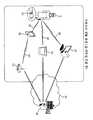
도 1은 종래 기술에 따른 생체 신호 센서 장치를 이용한 사용자 인터페이스 시스템의 한 예로서 손목 착용형 생체 신호 센서 장치를 이용한 유비쿼터스 건강 관리 시스템의 구성도이다.1 is a block diagram of a ubiquitous health care system using a wrist worn biosignal sensor device as an example of a user interface system using a biosignal sensor device according to the related art.
이에 나타낸 바와 같이 종래의 유비쿼터스 건강 관리 시스템은, 기본적으로 사용자(1)의 손목 등에 착용된 상태에서 사용자(1)의 건강 정보를 수집하는 손목 착용형 생체 신호 장치(10)와 무선통신(20)을 통해 연결된 휴대용 단말(30), 홈서버(40) 및 컴퓨터(예로서, PC(Personal Computer))(50) 등을 포함한다.As shown in the related art, the conventional ubiquitous health management system basically wirelessly communicates with the wrist worn
PDA 등과 같은 휴대용 단말(30)은 무선랜(60) 및 무선랜 억세스포인트(70)를 이용하여 외부의 인터넷(80)을 통해서 건강관리 기관의 건강관리 서버(90)에 연결되고, 자체적으로 인터넷(80)에 연결이 가능한 홈서버(40) 또는 컴퓨터(50)의 경우에는 직접 건강관리 서버(90)에 연결된다.The
이러한 유비쿼터스 건강 관리 시스템은 손목 착용형 생체 신호 장치(10)가 사용자(1)의 건강 정보를 수시로 수집하며, 수집한 건강 정보는 휴대용 단말(30), 홈서버(40) 또는 컴퓨터(50)에 의해 건강관리 서버(90)로 전송된다.The ubiquitous health care system collects the health information of the
종래 기술에 따른 생체 신호 센서 장치를 이용한 사용자 인터페이스 시스템의 문제점을 도 1의 유비쿼터스 건강 관리 시스템을 통해 살펴보면, 유선 혹은 무선 통신의 거리 제한에서 오는 사용자에 대한 자유로운 이동성 지원의 제약이 있으며, 또한 여러 공간으로 이루어진 실제 사용 환경에 있어서 무선 통신이 가능하다 하더라도 사용자가 현재 위치하고 있는 공간이 어디인지 알아낼 수 없다는 문제점이 있다. 이러한 문제점은 언제 어디서나 건강 관리가 가능한 진정한 의미의 유비쿼터스 건강 관리 시스템을 구현하는데 있어서 해결 과제이며, 특히 특정 공간에서 시급을 다투는 심장마비, 실신 또는 거동불가 등의 긴급 상황 발생시에는 사용자를 구조하는데 필요한 위치 정보를 제공하는 기능은 매우 중요한 필수적인 해결 과제라 할 수 있다.Looking at the problem of the user interface system using a bio-signal sensor device according to the prior art through the ubiquitous health care system of Figure 1, there is a restriction of free mobility support for users coming from the distance limitation of wired or wireless communication, and also various spaces Even though wireless communication is possible in an actual use environment, there is a problem in that the user cannot find out where the space is currently located. This problem is a challenge in realizing a true ubiquitous health care system that can manage health anytime, anywhere, and it is necessary to rescue users in case of emergency such as heart attack, fainting or inability to fight urgently in a specific space. The ability to provide information is a very important and essential challenge.
한편, 종래에도 GPS(Global Positioning System)를 기반으로 하는 위치 인식 기술이 적용되기도 하였으나, GPS의 경우 실내에서는 사용이 불가능하므로 일상생활에 사용하기에는 문제점이 있다.On the other hand, although the conventional position recognition technology based on the GPS (Global Positioning System) has been applied, the GPS is not available indoors, there is a problem to use in everyday life.
또한, 종래의 손목 착용형 생체 신호 장치의 경우에는 그 기능 및 구조가 건강 관리 부분에만 집중되어 있어서 사용자로부터 센싱된 각종 생체 신호를 기반으로 사용자의 행동 및 감정 상태 등을 파악하면 다양한 유비쿼터스 서비스 장치와의 인터페이스로 활용할 수 있다는 측면에서는 많은 미비점이 있다.In addition, in the conventional wrist-wearing biosignal device, its function and structure are concentrated only in the health care part, and when the user's behavior and emotional state are grasped based on various biosignals sensed by the user, There are many shortcomings in that it can be used as an interface.
본 발명은 사용자의 생체 신호를 센싱하는 생체 신호 센서 장치의 위치 정보를 기반으로 하는 응용 서비스를 제공하는 사용자 인터페이스 시스템을 제공한다.The present invention provides a user interface system for providing an application service based on location information of a biosignal sensor device sensing a biosignal of a user.
본 발명의 일 관점으로서 생체 신호 센서 장치를 이용한 사용자 인터페이스 시스템은, 무선 센서 네트워크의 이동형 무선 센서 노드의 역할을 하며, 사용자의 생체 신호를 센싱하여 생체 신호 데이터를 송신하는 생체 신호 센서 장치와, 상기 사용자의 생활공간에 복수로 설치되어 상기 생체 신호 센서 장치와의 무선 통신을 수행하는 고정형 무선 센서 노드와, 상기 고정형 무선 센서 노드와 무선 통신으로 상호 연결하여 상기 무선 센서 네트워크를 구현하는 무선 싱크 노드와, 상기 무선 싱크 노드를 통해 전달되는 상기 생체 신호 데이터를 처리하여 상기 무선 센서 네트워크의 위치 정보를 기반으로 하는 응용 서비스를 제공하는 서비스 수단을 포함한다.As one aspect of the present invention, a user interface system using a biosignal sensor device, which serves as a mobile wireless sensor node of a wireless sensor network, senses a user's biosignal and transmits biosignal data; A fixed wireless sensor node installed in a plurality of living spaces of a user and performing wireless communication with the biosignal sensor device, and a wireless sink node interconnecting the fixed wireless sensor node by wireless communication to implement the wireless sensor network; And service means for processing the biosignal data transmitted through the wireless sink node to provide an application service based on location information of the wireless sensor network.
삭제delete
삭제delete
본 발명에서는 생체 신호 센서 장치와 더불어 사용자의 실내/외 생활 환경 곳곳에 설치된 저가의 무선 센서 노드들로 이루어진 센서 네트워크를 이용하여 자유로운 광역 사용자 이동성을 지원하고, 특정 공간에 설치된 무선 센서 노드와 사용자가 착용하고 있는 무선 센서 노드와의 연동을 통해서 현재 사용자의 위치 및 거동 상태를 파악 할 수 있게 한다. 이를 통해서 유비쿼터스 건강 관리 서비스뿐만 아니라 사용자의 신체/감정 상태 변화, 행동 및 명령 등을 파악하기 위한 사용자 인터페이스로 이용하여 어린이를 위한 교육/게임 및 행동 관리, 지능형 서비스 로봇, 컴퓨터 또는 디지털 가전과 같은 다양한 전자기기를 원격 제어하는 등의 다양한 유비쿼터스 응용 서비스를 효과적으로 제공할 수 있다.In the present invention, by using a sensor network consisting of low-cost wireless sensor nodes installed throughout the user's indoor / outdoor living environment in addition to the bio-signal sensor device, it supports free wide-area user mobility, wireless sensor nodes and users installed in a specific space It works with the wireless sensor node that you are wearing so that you can check the location and behavior of the current user. This is not only a ubiquitous health care service, but also a user interface for understanding the user's physical / emotional changes, behaviors, and commands, and can be used for education / game and behavior management for children, intelligent service robots, computers, or digital appliances. It can effectively provide various ubiquitous application services such as remote control of electronic devices.
이하, 본 발명의 바람직한 실시예를 첨부된 도면들을 참조하여 상세히 설명한다. 아울러 본 발명을 설명함에 있어, 관련된 공지 구성 또는 기능에 대한 구체적인 설명이 본 발명의 요지를 흐릴 수 있다고 판단되는 경우에는 그 상세한 설명을 생략한다.Hereinafter, exemplary embodiments of the present invention will be described in detail with reference to the accompanying drawings. In addition, in describing the present invention, when it is determined that the detailed description of the related known configuration or function may obscure the gist of the present invention, the detailed description thereof will be omitted.
도 2는 본 발명에 따른 생체 신호 센서 장치를 이용한 사용자 인터페이스 시스템의 구성도이다.2 is a block diagram of a user interface system using a biosignal sensor device according to the present invention.
이에 나타낸 바와 같이 본 발명에 따른 사용자 인터페이스 시스템은, 무선 센서 네트워크의 이동형 무선 센서 노드로서 사용자(1)의 손목 등에 착용된 상태에서 사용자(1)의 생체 신호를 센싱하는 생체 신호 센서 장치(110)와, 사용자(1)의 생활공간인 정원, 서재, 안방, 침실, 화장실, 거실 등에 복수로 설치되어 생체 신 호 센서 장치(110)와 무선 통신(20)을 수행하는 고정형 무선 센서 노드(120)와, 고정형 무선 센서 노드(120)와 무선 통신(20)으로 상호 연결하여 무선 센서 네트워크를 구현하는 무선 싱크 노드(130)와, 무선 싱크 노드(130)와 연결되어 생체 신호 센서 장치(110)에 의해 센싱된 생체 신호 데이터를 처리하여 무선 센서 네트워크의 위치 정보를 기반으로 하는 응용 서비스를 제공하는 서비스 장치(141, 142, 143)와, 서비스 장치(141, 142, 143)와 인터넷(80) 등과 같은 외부 통신망을 통해 연결되어 서비스 장치(141, 142, 143)를 통해 생체 신호 데이터에 기초한 각종 서비스를 제공하는 서비스 서버(150)와, 생체 신호 센서 장치(110)를 보조하기 위해 사용자의 영상을 획득하는 보조 센서 장치(도시 생략됨)를 포함한다.As described above, the user interface system according to the present invention is a mobile wireless sensor node of a wireless sensor network, and the biological
서비스 장치(141, 142, 143)는 생체 신호 센서 장치(110)에 의해 센싱된 생체 신호 데이터를 기반으로 하여 각종 응용 서비스를 제공하는 장치로서, 무선 싱크 노드(130) 및 인터넷(80)과의 접속 기능을 가지는 컴퓨터(141), 무선 싱크 노드(130) 및 인터넷(80)과의 접속 기능을 가지며 홈네트워크를 구현하는 홈서버(142), 무선 싱크 노드(130)와의 접속 기능과 무선랜(60) 및 무선랜 억세스 포인트(70)를 통한 인터넷(80)과의 접속 기능을 가지는 지능형 로봇(143) 등으로 구현할 수 있다. 한편 컴퓨터(141), 홈서버(142), 지능형 로봇(143) 등의 경우에는 자체의 처리 능력이 우수하여 각종 응용 서비스를 제공하는 데에 손색이 없으므로 단독으로 서비스 장치로 작용할 수 있으나, 무선 싱크 노드(130)에 연결된 임의의 서비스 장치가 각종 응용 서비스를 제공하기에는 자체의 처리 능력이 적합하지 않을 때에는 적합한 성능을 갖는 별도의 호스트(host) 장치를 서비스 장치와 연결하여 사용할 수도 있다. 이러한 서비스 장치와 호스트 장치는 무선 싱크 노드(130)를 통해 전달되는 생체 신호 데이터를 처리하여 무선 센서 네트워크의 위치 정보를 기반으로 하는 응용 서비스를 제공하는 서비스 수단의 일 실시예인 것이다.The
고정형 무선 센서 노드(120)는 고유한 ID(identification)를 가지며, 상호간의 통신은 단대단(End-to-end) 통신에 있어서 무선 통신 거리의 제약을 받지 않는 다중홉(Multi-hop) 방식을 기반으로 하고, 생체 신호 센서 장치(110)인 이동형 무선 센서 노드는 센서 네트워크와의 항시 연결성 보장을 위하여 이동시 주변의 가장 근접한 무선 센서 노드로 자동 연결하는 이동성 지원 절차(Hand-over)를 수행한다.Fixed
또한, 생체 신호 센서 장치(110)에 현재 연결된 고정형 무선 센서 노드(120)를 위치 참조 노드로 하여 현재 사용자가 위치하고 있는 공간(안방, 침실, 거실 등)을 찾아낸다.In addition, the fixed
생체 신호 센서 장치(110) 및 센서 네트워크를 통해 수집된 사용자의 움직임, 생체 정보 및 위치 정보는 컴퓨터(141), 홈서버(142) 및 지능형 로봇(143) 등과 같은 서비스 장치의 자체적인 응용 프로그램을 통해서 사용자에서 서비스를 제공하기 위해 이용되거나, 인터넷(80)에 연결된 서비스 서버(150)에게 제공되어 보다 전문적인 응용 서비스 제공에 활용된다. 서비스 서버(150)는 의료기관의 CDSS(Clinical Decision Support System) 등으로 구현한다.The movement, biometric information, and location information of the user, collected through the
도 3은 본 발명에 따른 사용자 인터페이스 시스템을 구성하는 생체 신호 센서 장치, 무선 센서 노드 및 무선 싱크 노드의 세부 구성도이다.3 is a detailed configuration diagram of a biosignal sensor device, a wireless sensor node, and a wireless sink node configuring a user interface system according to the present invention.
도 3을 참조하면, 생체 신호 센서 장치(110)는 사용자의 신체 상태 또는 움 직임을 센싱하여 생체 신호 데이터를 생성하는 감지부(111)와, 생체 신호 데이터에 대한 고정형 무선 센서 노드(120)와의 무선 데이터 송수신을 수행하는 무선 통신부(112)와, 무선 통신부(112)와 고정형 무선 센서 노드(120) 사이의 단대단 다중홉 통신 및 이동성 지원 절차를 위한 프로토콜을 처리하는 센서넷 프로토콜 처리부(113)와, 무선 데이터 송수신과 단대단 다중홉 통신 및 이동성 지원 절차를 관장하는 프로세서부(114)와, 감지부(111)와 프로세서부(114)를 연결하는 접속부(115)를 포함한다. 감지부(111)는 맥박 또는 맥파 센서(111a), 혈압 센서(111b), 심전도 센서(111c), 체온 센서(111d), 혈당 센서(111e), 가속도 센서(111f), 각속도 센서(111g)를 포함하며, 센서넷 프로토콜 처리부(113)는 독립된 하드웨어 또는 펌웨어로 구현한다. 무선 통신부(112)는 지그비(Zigbee)(IEEE802.15.4), 블루투스(Bluetooth) 등과 같은 표준 무선 통신 또는 일반적인 허용 주파수대의 RF 통신 등으로 구현한다. 이와 같은 생체 신호 센서 장치(110)는 손목 밴드 또는 손목 시계 등과 같이 손목에 착용할 수 있는 형태를 가진다.Referring to FIG. 3, the
고정형 무선 센서 노드(120)는 생체 신호 센서 장치(110) 및 무선 싱크 노드(130)와의 무선 데이터 송수신을 수행하는 무선 통신부(121)와, 무선 통신부(121)와 생체 신호 센서 장치(110) 사이의 단대단 다중홉 통신 및 이동성 지원 절차를 위한 프로토콜을 처리하는 센서넷 프로토콜 처리부(122)와, 무선 데이터 송수신과 단대단 다중홉 통신 및 이동성 지원 절차를 관장하는 프로세서부(123)와, 사용자의 생활 환경을 센싱하는 감지부(124)와, 감지부(124)와 프로세서부(123)를 연결하는 접속부(125)를 포함한다. 감지부(124)는 온도 센서(124a), 습도 센 서(124b), 조도 센서(124c)를 포함한다. 한편, 환경 센싱이 필요하지 않은 경우에는 온도 센서(124a), 습도 센서(124b), 조도 센서(124c), 접속부(125)를 제외하고 고정형 무선 센서 노드(120)를 구현할 수도 있다. 이러한 고정형 무선 센서 노드(120)는 생활 공간에 쉽게 부착할 수 있는 외부 형태를 가진다.The fixed
무선 싱크 노드(130)는 고정형 무선 센서 노드(120)와의 무선 데이터 송수신을 수행하는 무선 통신부(131)와, 무선 통신부(131)와 고정형 무선 센서 노드(120) 사이의 단대단 다중홉 통신을 위한 프로토콜을 처리하는 센서넷 프로토콜 처리부(132)와, 무선 데이터 송수신과 단대단 다중홉 통신을 관장하는 프로세서부(133)와, 프로세서부(133)와 서비스 장치(141, 142, 143)를 연결하는 접속부(134)를 포함한다. 접속부(134)는 RS-232C 및 USB(Universal Serial Bus) 등과 같은 직렬 통신을 사용할 수 있다.The
도 4는 본 발명에 따른 서비스 장치의 세부 구성도이다. 앞서 설명한 바와 같이 서비스 장치(141, 142, 143)는 위치 정보를 기반으로 하는 응용 서비스를 제공하는 서비스 수단의 일 실시예로서, 서비스 수단은 서비스 장치와 별도의 호스트 장치를 연결하여 구현할 수도 있으며, 이 경우에 호스트 장치가 도 4에 나타낸 바와 같은 세부적인 구성을 가진다. 아울러 각 구성요소들은 하드웨어, 소프트웨어 또는 펌웨어로 구현할 수 있다.4 is a detailed configuration diagram of a service device according to the present invention. As described above, the
도 4를 참조하면, 서비스 장치(141, 142, 143) 또는 호스트 장치는 무선 싱크 노드(130)와의 연결을 제공하는 싱크 노드 접속부(201)와, 무선 싱크 노드(130)와의 통신을 지원하기 위한 기본 라이브러리를 제공하는 싱크 노드 API(application programming Interface)부(202)와, 무선 싱크 노드(130)로부터 전송되는 생체 신호 데이터에 대한 필터링 및 변환 등과 같은 전처리를 수행하는 센서 신호 처리부(203)와, 전처리된 생체 신호 데이터에 대해 HMM(Hidden Markov Model), 신경망 등의 학습/인식 알고리즘을 적용하여 패턴을 해석하는 센서 데이터 해석부(204)와, 무선 싱크 노드(130)로부터의 전송되는 생체 신호 데이터에 포함된 근접 센서 노드 ID를 기반으로 사용자의 현재 위치 정보를 센서맵 데이터베이스(DB)로부터 알아내는 사용자 위치관리부(205)와, 생체 신호 센서 장치(110)를 보조하기 위해 사용자의 영상을 획득하는 보조 센서 장치(도시 생략됨)에 의해 획득한 데이터와 센서 데이터 해석부(204)에 의해 해석된 생체 신호 데이터를 결합하여 의미 있는 새로운 컨텍스트를 추출하는 센서 데이터 합성부(206)와, 응용 서비스의 프로그램 개발을 위한 라이브러리를 제공하는 서비스 API부(207)와, 해석된 생체 신호 데이터 또는 센서 데이터 합성부(206)에 의해 합성된 데이터 및 위치 정보를 기반으로 서비스 장치(141, 142, 143)를 통해 사용자에게 응용 서비스를 제공하는 응용 서비스부(208)와, 서비스 서버(150)와의 연동을 제공하는 서버 연동부(209)를 포함한다. 여기서 근접 센서 노드 ID는 도 5를 참조한 아래의 설명으로부터 이해할 수 있으며, 센서맵 DB는 도 6를 참조한 아래의 설명으로부터 이해할 수 있다.Referring to FIG. 4, the
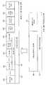
도 5는 본 발명에 따른 사용자 인터페이스 시스템에서 이용되는 생체 신호 데이터의 전송을 위한 센서넷 프로토콜 패킷 포맷의 구조도이다.5 is a structural diagram of a sensornet protocol packet format for transmitting biosignal data used in a user interface system according to the present invention.
도 5를 참조하면 센서넷 프로토콜 패킷(300)은 센서넷 프로토콜 헤더(310)와 센서넷 프로토콜 패이로드(payload)(320)를 포함하며, 센서넷 프로토콜 패이로 드(320)는 현 센서 데이터를 전송하는 센서 노드의 고유 ID인 센서 노드 ID 필드(321), 현 센서 데이터 메시지 종류(제어 데이터 또는 센싱 데이터)를 나타내는 센서 메시지 타입 필드(322), 현 센서 노드가 연결되어 있는 근접 센서 노드의 고유 ID인 근접 센서 노드 ID 필드(323), 현재 센서 데이터 메시지에 포함된 센서 데이터의 개수를 나타내는 센서 데이터 개수 필드(324) 및 센서 데이터 개수만큼의 실제 센싱된 센서 데이터 필드(325, 326)를 포함한다. 센서 데이터 필드(325, 326)는 데이터를 센싱한 센서의 종류(가속도, 각속도, 맥박, 혈압, 체온 등)를 나타내는 센서 타입(301), 해당 센서 데이터에 포함된 센서값의 개수(302) 및 센서값 개수만큼의 센싱된 데이터 값(303, 304)을 포함한다.Referring to FIG. 5, the
이와 같이 여러 개의 센서값을 모아서 전송하는 이유는 실제로 센서 데이터를 전송하는 간격(It)이 센서 노드에서 데이터를 센싱(Is)하는 간격보다 큰 경우(It > Is) 전송과 전송 사이에도 계속 센싱되는 데이터의 손실을 방지하기 위함이다. 이러한 기본적인 필드들 외에도 추가적으로 응용에 적합한 다양한 메시지 정보를 포함하는 필드를 추가하여 구성할 수도 있다.The reason for collecting multiple sensor values in this way is that if the interval (It) for transmitting sensor data is actually larger than the interval (It> Is) for sensing data at the sensor node (It> Is), it is continuously sensed between transmission and transmission. This is to prevent data loss. In addition to these basic fields, a field including various message information suitable for an application may be additionally configured.
도 6은 본 발명에 따른 사용자 인터페이스 시스템에서 서비스 장치(141, 142, 143)의 사용자 위치관리부(205)가 근접 센서 노드 ID(323)를 키(key)로 하여 해당 센서 노드가 설치되어 있는 공간명과 좌표 정보를 검색할 수 있는 형태를 가지는 센서맵 DB(400)의 구조도이다.6 is a space in which the corresponding user node is installed using the proximity
도 6을 참조하면 센서맵 DB(400)는 키로 사용되는 센서 노드 ID 필드(401), 서비스 환경에 적합하게 정의된 공간명(안방, 거실, 정원 등)을 저장하는 센서 공 간명 필드(402) 및 2차원 또는 3차원 좌표 체계로 해당 센서 노드의 좌표를 저장하고 있는 센서 좌표 필드(403)를 포함한다. 이러한 기본적인 필드들 외에도 추가적으로 응용에 적합한 다양한 센서 정보를 포함하는 필드를 추가하여 구성할 수도 있다.Referring to FIG. 6, the
이와 같은 센서맵 DB(400)를 이용함에 따라 사용자 위치관리부(205)는 생체 신호 데이터에 포함되어 전송된 근접 센서 노드 ID(323)를 기반으로 센서맵 DB(400)를 검색하여 사용자의 현재 위치 정보를 알아낸다.As the
도 7은 본 발명에 따른 사용자 인터페이스 시스템에서 이동형 무선 센서 노드인 생체 신호 센서 장치(110)와 지능형 로봇(143)에 장착되는 무선 싱크 노드(130)의 이동성을 지원하는 절차의 일 실시예를 나타낸 것이다. 이동하는 무선 센서 노드 또는 무선 싱크 노드는 리프(leaf) 노드이고 서비스 공간상에 고정된 무선 노드들은 라우터(router) 노드로 동작하는 트리(tree) 토폴로지 기반의 센서 네트워크 상에서의 실시예이다. 이러한 센서 네트워크 상에서의 이동성 지원 절차는 서비스 공간 상에서 움직이는 노드인 생체 신호 센서 장치(110)와 지능형 로봇(143)에 장착되는 싱크 노드가 항상 센서 네트워크에 연결되어 통신이 가능하도록 지원해주는 일종의 핸드오버(Hand-over) 프로토콜이다.7 illustrates an embodiment of a procedure for supporting mobility of a
(S11)(S11)
현재 사용자가 손목에 착용하고 있는 생체 신호 센서 장치(110)가 화장실에 설치된 고정형 무선 센서 노드(120)를 통해 센서넷과 연결(601)되어 있다고 가정한다(즉, 현재 사용자가 화장실에 있다고 가정).It is assumed that the
(S12)(S12)
사용자가 이동(602)하여 안방으로 들어갔다고 할 때, 화장실에 설치된 고정형 무선 센서 노드(120)의 무선 전파 도달 범위를 벗어나게 되므로 기존의 센서넷 연결은 끊어지게 된다(603)(즉, 사용자가 착용하고 있는 센서 노드가 센서넷으로부터 연결이 끊어짐).When the user moves 602 and enters the inside of the room, since the radio wave coverage of the fixed
(S13)(S13)
연결이 끊어짐을 감지한 생체 신호 센서 장치(110)는 주변의 전파 범위에 있는 센서 노드를 재탐색한다(604).The
(S14)(S14)
생체 신호 센서 장치(110)는 안방에 있는 고정형 무선 센서 노드(120)와 거실에 있는 고정형 무선 센서 노드(120) 중에서 탐색에 성공한, 즉 근접한 무선 센서 노드(120)에 새로운 연결(605)을 설정하게 된다.The
이와 같이 새롭게 탐색되어 연결된 센서 노드의 ID는 현재 사용자가 위치하고 있는 공간을 알아내기 위한 키로서 상술한 센서넷 프로토콜 패킷의 근접 센서 노드 ID(323) 필드에 저장되어 전송되며, 사용자 위치관리부(205)에 의해 도 6의 센서맵 DB(400)를 검색하는데 사용된다.The ID of the newly discovered and connected sensor node is stored in the proximity
도 8은 본 발명에 따른 사용자 인터페이스 시스템에서 이동형 무선 센서 노드인 생체 신호 센서 장치(110)와 지능형 로봇(143)에 장착되는 무선 싱크 노드(130)의 이동성을 지원하는 절차의 다른 실시예를 나타낸 것이다. 도 7과 마찬가 지로 이동하는 센서 노드는 리프 노드이고 서비스 공간상에 고정된 무선 노드들은 라우터 노드로 동작하는 트리 토폴로지 기반의 센서 네트워크 상에서의 실시예이다.8 illustrates another embodiment of a procedure for supporting mobility of a
(S21)(S21)
현재 사용자가 손목에 착용하고 있는 생체 신호 센서 장치(110)는 서비스 환경 상에 설치된 주변의 모든 고정형 무선 센서 노드(120)로부터 주기적으로 헬로우(Hello) 메시지(701)를 수신한다. 헬로우 메시지는 수신된 전파 신호 강도값(Received Signal Strength Indicator, RSSI)의 측정을 통하여 현재 가장 가까운 곳에 위치한 센서 노드를 찾기 위한 것이다.The
(S22)(S22)
생체 신호 센서 장치(110)는 수집한 헬로우 메시지들을 기반으로 도 9와 같은 근접 노드 테이블을 생성하고 유지하면서, 가장 무선 신호 강도가 강한 센서 노드(즉, 가장 가까운 위치에 있는 센서 노드)에게 연결(702)을 설정한다.The
여기서, 도 9를 참조하여 근접 노드 테이블(800)을 살펴보면, 주변의 고정형 무선 센서 노드(120)의 ID를 저장하는 센서 노드 ID 필드(801), 각각의 고정형 무선 센서 노드들의 수신 전파 신호 강도를 저장하는 무선 신호 강도 필드(802), 해당 근접 노드 테이블 엔트리가 생성되거나 마지막으로 변경된 시간을 기록함으로써 정해진 기간 동안 갱신되지 않는 센서 노드 엔트리를 검색하여 근접 노드 테이블(800)로부터 삭제하는데 사용되는 타임스템프 필드(803)를 포함한다. 근접 노드 테이블(800)은 이러한 기본적인 필드들 외에도 추가적으로 응용에 적합한 다양한 근접 노드 정보를 포함하는 필드를 추가하여 구성할 수도 있다.Here, referring to the proximity node table 800 with reference to FIG. 9, the sensor
(S23)(S23)
사용자가 이동(703)하여 안방으로 들어갔다고 할 때도 계속 주변의 고정형 무선 센서 노드(120)들로부터 헬로우 메시지(704)를 수신한다.Even when the user moves 703 and enters the home, the user continues to receive the
(S24)(S24)
사용자가 이동한 이후에 생체 신호 센서 장치(110)는 수집한 헬로우 메시지들을 기반으로 가장 무선 신호 강도가 강한 센서 노드(즉, 가장 가까운 위치에 있는 센서 노드)를 선택하여 연결(705)을 재설정한다.After the user moves, the
이하에서는 지금까지 설명한 본 발명에 따른 사용자 인터페이스 시스템을 특정한 응용 서비스의 제공을 위해 다양하게 구현한 예를 도 10 내지 도 14를 참조하여 살펴보기로 한다. 이하에서 설명할 구현 예는 어린이 행동 관리(Childcare) 서비스, 노약자/유아 관리(Elderycare/Enfantcare) 서비스, 게임/교육(Edutainment) 서비스, 유비쿼터스 건강 관리(u-Healthcare) 서비스, 전자기기 원격 제어 서비스 등이다. 이러한 서비스들은 기본적으로 독립적인 시스템을 통하여 제공될 수 있지만, 두 가지 이상의 서비스가 하나의 시스템에 통합되어 복합적인 형태의 서비스로도 제공이 가능하다.Hereinafter, various examples of implementing the user interface system according to the present invention described above to provide a specific application service will be described with reference to FIGS. 10 to 14. Embodiments to be described below include Childcare services, Elderycare / Enfantcare services, Gaming / Edutainment services, u-Healthcare services, and electronic device remote control services. to be. These services can be provided through basically independent systems, but two or more services can be integrated into a single system and can be provided as a complex service.
도 10은 생체 신호 센서 장치를 이용한 사용자 인터페이스 시스템을 통해 어린이 행동 관리 서비스를 제공하기 위한 구현 예이다.10 is an implementation example for providing a child behavior management service through a user interface system using a biosignal sensor device.
도 10을 참조하면 어린이 행동 관리 서비스는 생체 신호 센서 장치(110)를 이용하여 어린이의 행동을 센싱하고, 센서 네트워크를 통해 지능형 로봇(143) 또는 홈서버(142) 등의 서비스 장치가 모니터링 및 해석하여 기록하거나 보호자에게 실시간으로 보고하는 서비스이다.Referring to FIG. 10, the child behavior management service senses a child's behavior using the
어린이에게 생체 신호 센서 장치(110)를 착용하도록 하고 관리해야할 어린이의 행동(수면, 식사, 게임 및 기타 다양한 행동)을 파악하기 위해 필요한 가속도, 각속도, 맥박, 혈압, 위치(침실, 부엌, 컴퓨터방 및 기타 공간) 등의 데이터를 센싱(901∼903)하도록 한다. 센싱된 데이터(904)는 센서 네트워크를 이용하여 지능형 로봇(143)에 전송되며, 지능형 로봇(143)은 전송된 센서 데이터(904)에 대하여 센서 데이터 신호 처리를 통해 전처리(905)를 수행한다. 전처리가 완료된 센서 데이터는 센서 데이터 해석을 통해서 어떠한 행동인지 파악되고, 위치 파악을 통해서 현재 센서를 착용한 어린이의 위치를 알아내게 된다(906). 해석된 각각의 센서 데이터와 위치 데이터는 데이터 합성 과정을 통해 최종적으로 어떠한 의미의 행동인지 파악되며(907), 어린이 행동 관리 응용(908)을 통해서 실시간으로 보호자에게 보고(909)되거나 행동 내용 기록을 위한 데이터베이스에 저장(910)된다. 또한 보조 센서 장치로서 보조 시각 센서(911)가 지능형 로봇(143)에 장착된 경우에는 지능형 로봇(143)을 현재 사용자의 위치로 이동시켜서 보조 시각 센서(911)로부터 영상처리를 통해 생성된 사용자의 자세(pose) 데이터 등과 같은 보조 데이터를 합성에 사용하면 보다 정확한 행동 파악을 수행할 수 있으며, 지능형 로봇(143)에 장착된 음성 출력장치나 스피커 등을 통하여 어린이의 행동을 통제하거나 제한하는 말을 자동으로 출력하거나 보호자가 실시간으로 어린이와가 대화할 수 있도록 하여 보다 지능적이고 효과적인 서비스를 제공할 수 있다.Acceleration, angular velocity, pulse rate, blood pressure, location (bedroom, kitchen, computer room) to require the child to wear the
도 11은 생체 신호 센서 장치를 이용한 사용자 인터페이스 시스템을 통해 노약자/유아 관리 서비스를 제공하기 위한 구현 예이다.11 is an implementation example for providing the elderly / infant management service through a user interface system using a bio-signal sensor device.
도 11을 참조하면 노약자/유아 관리 서비스는 생체 신호 센서 장치(110)를 이용하여 거동이 불편하거나 의사표현이 자유롭지 못한 노인 혹은 유아의 상태를 센싱하고, 센서 네트워크를 통해 지능형 로봇(143) 또는 홈서버(142) 등의 서비스 장치가 모니터링 및 해석하여 기록하거나 응급 구조대 호출 또는 보호자에게 실시간으로 보고하는 서비스이다.Referring to FIG. 11, the elderly / infant management service senses a state of an elderly or infant who is inconvenient in motion or incapable of expressing expression using the
노인 또는 유아에게 생체 신호 센서 장치(110)를 착용하도록 하고 관찰해야할 상태(수면시 움직임, 낙상, 유아의 체온 및 기타 다양한 상태)를 파악하기 위해 필요한 가속도, 각속도, 맥박, 혈압, 체온, 위치 등의 데이터를 센싱(1001∼1003)하도록 한다. 센싱된 데이터(1004)는 센서 네트워크를 이용하여 지능형 로봇(143)에 전송되며, 지능형 로봇(143)은 전송된 센서 데이터(1004)에 대하여 센서 데이터 신호 처리(1005)를 통해 전처리를 수행한다. 전처리가 완료된 센서 데이터는 센서 데이터 해석을 통해서 어떠한 상태인지 파악되고, 위치 파악을 통해서 현재 센서를 착용한 노인 및 유아의 위치를 알아내게 된다(1006). 해석된 각각의 센서 데이터와 위치 데이터는 데이터 합성(1007) 과정을 통해 최종적으로 어떠한 의미의 행동인지 파악되며, 노약자 상태 관리 응용(1008)을 통해서 실시간으로 보호자에게 보고(1009)되거나 응급 구조대를 호출(1010) 또는 행동 내용 기록을 위한 데이터베이스에 저장(1011)된다. 또한 보조 센서 장치로서 보조 시각 센서(1012)가 지능형 로봇(143)에 장착된 경우에는 지능형 로봇(143)을 현재 사용자의 위치로 이동시켜서 보조 시각 센서(1012)로부터 영상처리를 통해 생성된 사용자의 자세(pose) 데이터 등과 같은 보조 데이터를 합성에 사용하면 보다 정확한 행동 파악을 수행할 수 있으며, 지능형 로봇(143)에 장착된 음성 출력장치나 스피커 등을 통하여 사용자가 안심할 수 있는 말을 자동으로 출력하거나 보호자 또는 응급 구조 요원 등과 실시간으로 사용자가 대화할 수 있도록 하여 보다 지능적이고 효과적인 서비스를 제공할 수 있다.Acceleration, angular velocity, pulse rate, blood pressure, body temperature, position, etc., required to allow the elderly or infant to wear the
도 12는 생체 신호 센서 장치를 이용한 사용자 인터페이스 시스템을 통해 게임/교육 서비스를 제공하기 위한 구현 예이다.12 is an implementation example for providing a game / education service through a user interface system using a biosignal sensor device.
도 12를 참조하면 게임/교육 서비스는 조이스틱이나 기타 기존의 게임 인터페이스 장치 또는 마우스나 키보드 같은 일반적인 사용자 인터페이스 장치를 사용하는 것이 아니라 생체 신호 센서 장치(110)를 착용한 사용자의 팔의 움직임 및 사용자의 신체 상태 변화를 센싱하여 센서 네트워크를 통해 컴퓨터, 지능형 로봇 또는 홈서버 등의 서비스 장치에 전송하고 센서 데이터에 대한 해석을 통해 다양한 게임이나 교육 응용 프로그램 및 컨텐츠를 제공하는 서비스이다.Referring to FIG. 12, the game / education service does not use a joystick or other conventional game interface device or a general user interface device such as a mouse or a keyboard, but moves the arm of the user who wears the
어린이와 같은 게임/교육 서비스 사용자에게 생체 신호 센서 장치(110)를 착용하도록 하고 게임이나 교육 응용 프로그램 또는 컨텐츠를 수행하기 위하여 필요한 사용자의 행동 및 상태를 파악하기 위해 필요한 가속도, 각속도, 맥박, 위치 등의 데이터를 센싱(1101)하도록 한다. 센싱된 데이터(1102)는 센서 네트워크를 이용하여 지능형 로봇(143)에 전송되며, 지능형 로봇(143)은 전송된 센서 데이터(1102)에 대하여 센서 데이터 신호 처리를 통해 전처리(1103)를 수행한다. 전처리가 완료 된 센서 데이터는 센서 데이터 해석을 통해서 사용자가 게임/교육을 위하여 어떠한 행동을 수행하고 어떠한 상태인지 파악되고, 위치 파악을 통해서 현재 센서를 착용한 사용자의 위치를 알아내게 된다(1104). 해석된 각각의 센서 데이터와 위치 데이터는 데이터 합성(1105) 과정을 통해 최종적으로 어떠한 의미의 행동인지, 어떠한 의미의 상태인지 파악되며, 게임/교육 응용 및 컨텐츠(1106)를 통해서 사용자에게 서비스를 제공하게 된다. 이러한 게임/교육 서비스에 있어서 가속도 및 각속도 센서를 통해 얻어진 사용자의 움직임 데이터는 게임이나 교육에 있어서 사용자 입력 장치를 대체하는 수단으로 사용되며, 맥박 센서를 통해서 얻어진 사용자의 신체 상태 데이터는 게임이나 교육 서비스 제공을 받은 사용자의 신체 변화를 알아내는데 사용된다. 게임 응용 프로그램의 일 실시예를 설명하면, 일정시간 동안의 게임을 수행한 사용자의 맥박을 센서 네트워크를 통해 모니터링하여 사용자의 지친 정도나 흥분한 상태 등을 알아내고 지능적으로 반응(1107)함으로써 보다 양질의 게임 서비스 제공에 활용할 수 있다. 사용자의 위치 데이터는 사용자 게임이나 교육 중에 다른 공간으로 이동했을 때 자동으로 종료하거나 또는 지능형 로봇(143)과 같은 이동이 가능한 서비스 장치를 이용하는 경우 지능형 로봇(143)과의 술래잡기 등의 위치 기반의 게임에 이용할 수 있다. 또한 보조 센서 장치로서 보조 시각 센서(1108)가 지능형 로봇(143)에 장착된 경우에는 지능형 로봇(143)에 장착된 보조 시각 센서(1108)로부터 영상처리를 통해 생성된 사용자의 자세나 게임 또는 교육에 사용하는 물건의 색깔 및 모양 데이터 등과 같은 보조 데이터를 합성에 사용하면 보다 정확한 사용자의 입력을 파악할 수 있어서 좀더 지능적이고 효과적인 게임/교육 서비 스를 제공할 수 있다.Acceleration, angular velocity, pulse rate, location, etc., required to allow the user of a game / educational service such as a child to wear the
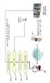
도 13은 생체 신호 센서 장치를 이용한 사용자 인터페이스 시스템을 통해 유비쿼터스 건강 관리 서비스를 제공하기 위한 구현 예이다.13 is an example of implementation for providing a ubiquitous health care service through a user interface system using a biosignal sensor device.
도 13을 참조하면 유비쿼터스 건강 관리 서비스는 생체 신호 센서 장치(110)를 이용하여 만성질환자의 신체 상태, 운동시의 신체 상태, 위급 상황시의 신체 상태 등을 센싱하고, 센서 네트워크를 통해 지능형 로봇(143) 또는 홈서버(142) 등의 서비스 장치가 모니터링 및 해석하여 정기 투약 및 혈압/혈당 측정 관리, 운동량 관리 또는 필요시 응급 구조대 호출을 수행하는 서비스이다.Referring to FIG. 13, the ubiquitous health care service senses a physical condition of a chronically ill patient, a physical state during exercise, a physical state in case of emergency by using the
건강관리가 필요한 사용자(만성질환자, 밤샘야근자 등)에게 생체 신호 센서 장치(110)를 착용하도록 하고 만성질환 관리, 운동량 관리 또는 실신/심장발작 등의 위급상황 관리를 위하여 필요한 맥박, 혈압, 체온, 혈당, 가속도, 각속도, 위치 등의 데이터를 센싱(1201∼1203)하도록 한다. 센싱된 데이터(1204)는 센서 네트워크를 이용하여 지능형 로봇(143)에 전송되며, 지능형 로봇(143)은 전송된 센서 데이터에 대하여 센서 데이터 신호 처리를 통해 전처리(1205)를 수행한다. 전처리가 완료된 센서 데이터는 센서 데이터 해석을 통해서 어떠한 상태인지 파악되고, 위치 파악을 통해서 현재 센서를 착용한 노인 및 유아의 위치를 알아내게 된다(1206). 해석된 각각의 센서 데이터와 위치 데이터는 데이터 합성(1207) 과정을 통해 최종적으로 어떠한 의미의 행동인지 파악되며, 건강 관리 응용(1208)을 통해서 정기 투약 및 혈압/혈당 측정 관리(1209), 운동량 관리(1210) 또는 필요시 응급 구조대 호출(1211) 등을 수행하게 된다. 특히 정기 투약 및 혈압/혈당 측정 기록과 평소의 운동량에 대한 기록은 사용자가 의료서비스를 받고 있는 의료기관의 서버(1212)에 기록되어 내원 진료를 위한 데이터로서 활용된다. 또한 보조 센서 장치로서 보조 시각 센서(1213)가 지능형 로봇(143)에 장착된 경우에는 지능형 로봇(143)을 현재 사용자의 위치로 이동시켜서 지능형 로봇(143)에 장착된 보조 시각 센서(1213)로부터 영상처리를 통해 생성된 사용자의 자세 데이터 등과 같은 보조 데이터를 합성에 사용하면 보다 정확한 상태 파악을 수행할 수 있으며, 지능형 로봇(143)에 장착된 음성 출력장치나 스피커 등을 통하여 투약시간 또는 혈압/혈당 측정 시간을 정기적으로 알리거나, 운동량에 대한 조언이나 위급상황시 사용자가 취할 수 있는 응급조치 방법을 알려주거나, 응급 구조 요원 등과 실시간으로 사용자가 대화할 수 있도록 하여 보다 지능적이고 효과적인 서비스를 제공할 수 있다.Users who need health care (chronic disease, overnight work, etc.) to wear the
도 14는 생체 신호 센서 장치를 이용한 사용자 인터페이스 시스템을 통해 전자기기 원격 제어 서비스를 제공하기 위한 구현 예이다.14 is an implementation example for providing an electronic device remote control service through a user interface system using a biosignal sensor device.
도 14를 참조하면 전자기기 원격 제어 서비스는 기존의 적외선을 이용한 버튼이나 조이스틱 방식의 리모트 컨트롤러를 사용하는 것이 아니라 생체 신호 센서 장치(110)를 착용한 사용자의 팔의 움직임을 센싱하여 센서 네트워크를 통해 컴퓨터(141), 홈서버(142) 또는 지능형 로봇(143) 등의 서비스 장치, 즉 전자기기를 서비스 공간 어느 곳에서나 원격 제어하는 서비스이다.Referring to FIG. 14, the electronic device remote control service senses the movement of a user's arm wearing the
사용자에게 생체 신호 센서 장치(110)를 착용하도록 하고 전자기기, 예로서 지능형 로봇(143)을 원격 제어하는데 필요한 사용자의 행동을 파악하기 위해 필요한 가속도, 각속도, 위치 등의 데이터를 센싱(1301)하도록 한다. 센싱된 데이 터(1302)는 센서 네트워크를 이용하여 제어 대상인 지능형 로봇(143)에게 전송되며, 지능형 로봇(143)은 전송된 센서 데이터에 대하여 센서 데이터 신호 처리를 통해 전처리(1303)를 수행한다. 전처리가 완료된 센서 데이터는 센서 데이터 해석을 통해서 사용자가 원격 제어를 위하여 어떠한 행동을 수행하였는지 파악되고, 위치 파악을 통해서 현재 센서를 착용한 사용자의 위치를 알아내게 된다(1304). 해석된 각각의 센서 데이터와 위치 데이터는 데이터 합성(1305) 과정을 통해 최종적으로 어떠한 의미의 제어 명령인지 파악되며, 전자기기 제어 응용(1306)을 통해서 지능형 로봇(143)을 직접 제어하게 된다. 또한 보조 센서 장치로서 보조 시각 센서(1307)가 지능형 로봇(143)에 장착된 경우에는 보조 시각 센서(1307)로부터 영상처리를 통해 생성된 사용자의 자세 등과 같은 보조 데이터를 합성에 사용하면 보다 정확한 사용자의 제어 명령을 파악할 수 있어서 좀더 지능적이고 효과적인 원격 제어 서비스를 제공할 수 있다.Have the user wear the
지금까지 본 발명의 일 실시예에 국한하여 설명하였으나 본 발명의 기술이 당업자에 의하여 용이하게 변형 실시될 가능성이 자명하다. 이러한 변형된 실시 예들은 본 발명의 특허청구범위에 기재된 기술사상에 포함된다고 하여야 할 것이다.It has been described so far limited to one embodiment of the present invention, it is obvious that the technology of the present invention can be easily modified by those skilled in the art. Such modified embodiments should be included in the technical spirit described in the claims of the present invention.
도 1은 종래 기술에 따른 생체 신호 센서 장치를 이용한 사용자 인터페이스 시스템의 한 예로서 유비쿼터스 건강 관리 시스템의 구성도,1 is a configuration diagram of a ubiquitous health care system as an example of a user interface system using a biosignal sensor device according to the prior art;
도 2는 본 발명에 따른 생체 신호 센서 장치를 이용한 사용자 인터페이스 시스템의 구성도,2 is a configuration diagram of a user interface system using a biosignal sensor device according to the present invention;
도 3은 본 발명에 따른 사용자 인터페이스 시스템을 구성하는 생체 신호 센서 장치, 무선 센서 노드 및 무선 싱크 노드의 세부 구성도,3 is a detailed configuration diagram of a biosignal sensor device, a wireless sensor node, and a wireless sink node configuring a user interface system according to the present invention;
도 4는 본 발명에 따른 서비스 장치의 세부 구성도,4 is a detailed configuration diagram of a service apparatus according to the present invention;
도 5는 본 발명에 따른 사용자 인터페이스 시스템에서 이용되는 생체 신호 데이터의 전송을 위한 센서넷 프로토콜 패킷 포맷의 구조도,5 is a structural diagram of a sensornet protocol packet format for transmitting biosignal data used in a user interface system according to the present invention;
도 6은 본 발명에 따른 사용자 인터페이스 시스템에서 이용되는 센서맵 데이터베이스의 구조도,6 is a structural diagram of a sensor map database used in a user interface system according to the present invention;
도 7은 본 발명에 따른 사용자 인터페이스 시스템에서 무선 센서 노드의 이동성을 지원하는 절차의 일 실시예를 나타낸 도면,7 is a diagram illustrating an embodiment of a procedure for supporting mobility of a wireless sensor node in a user interface system according to the present invention;
도 8은 본 발명에 따른 사용자 인터페이스 시스템에서 무선 센서 노드의 이동성을 지원하는 절차의 다른 실시예를 나타낸 도면,8 is a view showing another embodiment of a procedure for supporting mobility of a wireless sensor node in a user interface system according to the present invention;
도 9는 본 발명에 따른 센서 노드의 이동성 지원 절차를 위한 근접 노드 테이블 구성의 일실시예를 나타낸 도면,9 is a diagram illustrating an embodiment of a configuration of a proximity node table for a mobility support procedure of a sensor node according to the present invention;
도 10은 생체 신호 센서 장치를 이용한 사용자 인터페이스 시스템을 통해 어린이 행동 관리 서비스를 제공하기 위한 구현 예를 보인 도면,FIG. 10 is a diagram illustrating an implementation example for providing a child behavior management service through a user interface system using a biosignal sensor device; FIG.
도 11은 생체 신호 센서 장치를 이용한 사용자 인터페이스 시스템을 통해 노약자/유아 관리 서비스를 제공하기 위한 구현 예를 보인 도면,FIG. 11 is a diagram illustrating an implementation example for providing an elderly / infant management service through a user interface system using a biosignal sensor device; FIG.
도 12는 생체 신호 센서 장치를 이용한 사용자 인터페이스 시스템을 통해 게임/교육 서비스를 제공하기 위한 구현 예를 보인 도면,12 is a view showing an implementation example for providing a game / education service through a user interface system using a biosignal sensor device;
도 13은 생체 신호 센서 장치를 이용한 사용자 인터페이스 시스템을 통해 유비쿼터스 건강 관리 서비스를 제공하기 위한 구현 예를 보인 도면,FIG. 13 is a diagram illustrating an implementation example for providing a ubiquitous health care service through a user interface system using a biosignal sensor device; FIG.
도 14는 생체 신호 센서 장치를 이용한 사용자 인터페이스 시스템을 통해 전자기기 원격 제어 서비스를 제공하기 위한 구현 예를 보인 도면.FIG. 14 is a diagram illustrating an implementation for providing an electronic device remote control service through a user interface system using a biosignal sensor device. FIG.
Claims (32)
Translated fromKoreanPriority Applications (2)
| Application Number | Priority Date | Filing Date | Title |
|---|---|---|---|
| PCT/KR2008/001382WO2008150062A1 (en) | 2007-06-04 | 2008-03-12 | Biological signal sensor apparatus, wireless sensor network, and user interface system using biological signal sensor apparatus |
| US12/630,723US8787332B2 (en) | 2007-06-04 | 2009-12-03 | Biological signal sensor apparatus, wireless sensor network, and user interface system using biological signal sensor apparatus |
Applications Claiming Priority (2)
| Application Number | Priority Date | Filing Date | Title |
|---|---|---|---|
| KR20070054374 | 2007-06-04 | ||
| KR1020070054374 | 2007-06-04 |
Publications (2)
| Publication Number | Publication Date |
|---|---|
| KR20080106830A KR20080106830A (en) | 2008-12-09 |
| KR100928892B1true KR100928892B1 (en) | 2009-11-30 |
Family
ID=40367414
Family Applications (1)
| Application Number | Title | Priority Date | Filing Date |
|---|---|---|---|
| KR1020070102549AExpired - Fee RelatedKR100928892B1 (en) | 2007-06-04 | 2007-10-11 | User Interface System Using Biological Signal Sensor Device |
Country Status (2)
| Country | Link |
|---|---|
| US (1) | US8787332B2 (en) |
| KR (1) | KR100928892B1 (en) |
Families Citing this family (45)
| Publication number | Priority date | Publication date | Assignee | Title |
|---|---|---|---|---|
| KR101210277B1 (en) | 2008-12-23 | 2012-12-18 | 한국전자통신연구원 | System for activity monitoring and information transmission method for activity monitoring |
| KR101066535B1 (en)* | 2009-04-30 | 2011-09-21 | 동서대학교산학협력단 | Wireless multi-hop routing based biosignal monitoring system |
| TWI410232B (en)* | 2009-10-13 | 2013-10-01 | Univ Nat Taiwan | Vital signs system for monitoring |
| KR101312919B1 (en)* | 2009-12-21 | 2013-10-01 | 한국전자통신연구원 | Apparatus for detecting survival of animate being and method using the same |
| KR101299220B1 (en)* | 2010-01-08 | 2013-08-22 | 한국전자통신연구원 | Method for emotional communication between emotional signal sensing device and emotional service providing device |
| FR2964223B1 (en)* | 2010-08-31 | 2016-04-01 | Commissariat Energie Atomique | METHOD FOR CONFIGURING SENSOR DETECTION DEVICE, COMPUTER PROGRAM, AND CORRESPONDING ADAPTIVE DEVICE |
| WO2012031163A1 (en)* | 2010-09-01 | 2012-03-08 | Eric Douglass Clifton | Resource management and control system |
| KR101248323B1 (en)* | 2011-02-11 | 2013-03-27 | 한국과학기술원 | Method and Apparatus for providing Ubiquitous Smart Parenting and Customized Education Service, and Recording medium thereof |
| KR101226188B1 (en)* | 2011-04-25 | 2013-01-24 | 상지대학교산학협력단 | Remote patient monitoring system based on embedded terminal and sensor nodes |
| KR101234835B1 (en)* | 2011-04-26 | 2013-02-22 | (의료)길의료재단 | A hypertension monitoring and notification device based on context information |
| US8957858B2 (en)* | 2011-05-27 | 2015-02-17 | Microsoft Technology Licensing, Llc | Multi-platform motion-based computer interactions |
| BR112014000106A8 (en)* | 2011-07-05 | 2018-02-06 | Brain Sentinel Inc | METHOD AND DEVICE FOR DETECTING SEIZURES |
| US10276034B2 (en)* | 2011-07-20 | 2019-04-30 | Honeywell International Inc. | System and method for playing back wireless fire system history events |
| DE102011055898A1 (en)* | 2011-11-30 | 2013-06-06 | Emperra Gmbh E-Health Technologies | Telemedicine arrangement for diabetes mellitus patients |
| EP2653945B1 (en)* | 2012-04-19 | 2016-06-15 | Schneider Electric Buildings LLC | Association of a portable sensor device in a building management system |
| CN102871647A (en)* | 2012-09-25 | 2013-01-16 | 东信和平科技股份有限公司 | Mobile medical physiological detection system with region positioning function |
| EP2920670A4 (en)* | 2012-11-16 | 2016-06-29 | Nokia Technologies Oy | Transmission of motion data |
| US20140191880A1 (en)* | 2013-01-10 | 2014-07-10 | Covidien Lp | System, method, and software for ambulatory patient monitoring |
| KR102079535B1 (en)* | 2013-01-30 | 2020-02-20 | 삼성전자주식회사 | Apparatus and method for collecting sensor data for each user, TV and personalized sensing platform system |
| US20140285326A1 (en)* | 2013-03-15 | 2014-09-25 | Aliphcom | Combination speaker and light source responsive to state(s) of an organism based on sensor data |
| JP6054238B2 (en)* | 2013-04-26 | 2016-12-27 | 株式会社東芝 | Electronic device and communication control method |
| US9870690B2 (en)* | 2013-10-08 | 2018-01-16 | General Electric Company | Methods and systems for a universal wireless platform for asset monitoring |
| US10134226B2 (en) | 2013-11-07 | 2018-11-20 | Igt Canada Solutions Ulc | Methods and apparatus for controlling casino game machines |
| US9595181B2 (en)* | 2013-12-20 | 2017-03-14 | Invensense, Inc. | Wearable device assisting smart media application and vice versa |
| TWM483806U (en)* | 2014-03-04 | 2014-08-11 | Gang Zhao | Intelligent safety protection integration system carrier |
| US10531401B2 (en)* | 2014-03-20 | 2020-01-07 | Xiaomi Inc. | Method, terminal device and system for controlling transmission |
| CN103889040B (en)* | 2014-03-20 | 2019-01-04 | 小米科技有限责任公司 | Emission control method, apparatus and system |
| CN105376692B (en)* | 2014-08-19 | 2020-02-28 | 中兴通讯股份有限公司 | Method and device for information interaction between intelligent terminal and wearable device |
| WO2016029165A2 (en)* | 2014-08-22 | 2016-02-25 | Lutron Electronics Co., Inc. | Load control system responsive to location of an occupant and mobile devices |
| US10032353B2 (en)* | 2015-02-24 | 2018-07-24 | KiLife Tech, Inc. | Monitoring dependent individuals |
| US9928713B2 (en) | 2015-02-24 | 2018-03-27 | KiLife Tech, Inc. | Locks for wearable electronic bands |
| CN104856658B (en)* | 2015-05-26 | 2018-07-31 | 重庆大学 | Wearable intelligent guarding system based on Big Dipper positioning with physiological status monitoring |
| US9954778B2 (en)* | 2015-09-15 | 2018-04-24 | At&T Mobility Ii Llc | Gateways for sensor data packets in cellular networks |
| CN105611497A (en)* | 2015-10-30 | 2016-05-25 | 东莞酷派软件技术有限公司 | Wearable smart device and terminal, control method and control device thereof |
| US9760088B2 (en)* | 2016-02-09 | 2017-09-12 | King Fahd University Of Petroleum And Minerals | Method for cooperatively deploying robots and cooperative system of robots |
| US10769418B2 (en) | 2017-01-20 | 2020-09-08 | At&T Intellectual Property I, L.P. | Devices and systems for collective impact on mental states of multiple users |
| KR101957498B1 (en)* | 2017-02-02 | 2019-06-19 | 주식회사 링크노아 | Cow health care system and method based on big data analysis |
| US11112395B2 (en)* | 2017-02-24 | 2021-09-07 | Particles Plus, Inc. | Networked air quality monitoring system |
| US10810869B2 (en)* | 2017-02-24 | 2020-10-20 | Particles Plus, Inc. | Crowdsourced air quality monitoring system |
| CN109087705A (en)* | 2017-06-14 | 2018-12-25 | Gms股份有限公司 | Generate the electronic equipment and its control method of growth and development information |
| CN111315278B (en)* | 2017-08-04 | 2023-04-07 | 汉内斯·本特菲尔顿 | Adaptive interface for screen-based interaction |
| AU2020299778A1 (en)* | 2019-07-01 | 2022-02-17 | E-Solutions, Inc. | Emergency responding method, safety confirmation system, management device, space section, and method for controlling management device |
| US11570792B2 (en) | 2019-07-31 | 2023-01-31 | Carrier Corporation | System and method for configuring communication interval for sensing device/s |
| KR102634409B1 (en)* | 2020-04-28 | 2024-02-06 | 주식회사 아모센스 | System for remotely monitoring temperature |
| USD1069806S1 (en)* | 2021-02-08 | 2025-04-08 | Electronics And Telecommunications Research Institute | Display panel with graphical user interface |
Citations (4)
| Publication number | Priority date | Publication date | Assignee | Title |
|---|---|---|---|---|
| KR20020078327A (en)* | 2001-04-09 | 2002-10-18 | 주식회사 휴네텍 | Wireless body signal transfer system for medical diagonostics |
| KR20030061157A (en)* | 2002-01-11 | 2003-07-18 | 삼성전자주식회사 | Method and apparatus for understanding the condition of animal using acquisition and analysis of physiological signal of the animal |
| KR20060014837A (en)* | 2004-08-12 | 2006-02-16 | 주식회사 팬택앤큐리텔 | Home network control device using user's biosignal |
| KR20060070165A (en)* | 2004-12-20 | 2006-06-23 | 한국전자통신연구원 | Wireless Transmit / Receive Method for Dynamic Sensor Node Reconfiguration in Wireless Sensor Networks |
Family Cites Families (17)
| Publication number | Priority date | Publication date | Assignee | Title |
|---|---|---|---|---|
| US6893396B2 (en)* | 2000-03-01 | 2005-05-17 | I-Medik, Inc. | Wireless internet bio-telemetry monitoring system and interface |
| US7356561B2 (en)* | 2003-05-01 | 2008-04-08 | Lucent Technologies Inc. | Adaptive sleeping and awakening protocol for an energy-efficient adhoc network |
| US8795168B2 (en)* | 2003-07-17 | 2014-08-05 | Cadi Scientific Pte Ltd. | Method and system for capturing and monitoring a physiological parameter and movement within an area of at least one person |
| KR20050050350A (en) | 2003-11-25 | 2005-05-31 | 삼성전기주식회사 | Apparatus for diagnosing a living body and mobile phone using the same |
| US8417215B2 (en)* | 2004-07-28 | 2013-04-09 | Koninklijke Philips Electronics N.V. | Method for positioning of wireless medical devices with short-range radio frequency technology |
| US7590098B2 (en)* | 2004-10-27 | 2009-09-15 | Honeywell International Inc. | Publish/subscribe model in a wireless sensor network |
| KR100682995B1 (en)* | 2004-12-16 | 2007-02-15 | 한국전자통신연구원 | Ubiquitous based context information service system and method |
| KR100628380B1 (en) | 2004-12-17 | 2006-09-27 | 한국전자통신연구원 | Sensing device for implementing ubiquitous system and mobile terminal device using same |
| KR100666983B1 (en)* | 2004-12-22 | 2007-01-10 | 삼성전자주식회사 | Context transmission system and method for handover of terminal on wireless network |
| US20060229520A1 (en)* | 2005-04-08 | 2006-10-12 | Shunzo Yamashita | Controller for sensor node, measurement method for biometric information and its software |
| US20060247505A1 (en)* | 2005-04-28 | 2006-11-02 | Siddiqui Waqaas A | Wireless sensor system |
| US7970574B2 (en)* | 2005-06-22 | 2011-06-28 | The Board Of Trustees Of The Leland Stanford Jr. University | Scalable sensor localization for wireless sensor networks |
| JP4580305B2 (en)* | 2005-08-01 | 2010-11-10 | 株式会社日立製作所 | Computer system and radio base station |
| JP4839152B2 (en)* | 2006-08-04 | 2011-12-21 | 株式会社日立製作所 | Sensor network system and sensor network data processing method |
| US8226474B2 (en)* | 2006-09-08 | 2012-07-24 | Igt | Mobile gaming devices for use in a gaming network having gaming and non-gaming zones |
| KR100745725B1 (en)* | 2006-09-29 | 2007-08-03 | 한국전자통신연구원 | Synchronization system and method of sensor network for low power |
| US8510567B2 (en)* | 2006-11-14 | 2013-08-13 | Cfph, Llc | Conditional biometric access in a gaming environment |
- 2007
- 2007-10-11KRKR1020070102549Apatent/KR100928892B1/ennot_activeExpired - Fee Related
- 2009
- 2009-12-03USUS12/630,723patent/US8787332B2/ennot_activeExpired - Fee Related
Patent Citations (4)
| Publication number | Priority date | Publication date | Assignee | Title |
|---|---|---|---|---|
| KR20020078327A (en)* | 2001-04-09 | 2002-10-18 | 주식회사 휴네텍 | Wireless body signal transfer system for medical diagonostics |
| KR20030061157A (en)* | 2002-01-11 | 2003-07-18 | 삼성전자주식회사 | Method and apparatus for understanding the condition of animal using acquisition and analysis of physiological signal of the animal |
| KR20060014837A (en)* | 2004-08-12 | 2006-02-16 | 주식회사 팬택앤큐리텔 | Home network control device using user's biosignal |
| KR20060070165A (en)* | 2004-12-20 | 2006-06-23 | 한국전자통신연구원 | Wireless Transmit / Receive Method for Dynamic Sensor Node Reconfiguration in Wireless Sensor Networks |
Also Published As
| Publication number | Publication date |
|---|---|
| KR20080106830A (en) | 2008-12-09 |
| US20100160744A1 (en) | 2010-06-24 |
| US8787332B2 (en) | 2014-07-22 |
Similar Documents
| Publication | Publication Date | Title |
|---|---|---|
| KR100928892B1 (en) | User Interface System Using Biological Signal Sensor Device | |
| Cao et al. | Enabling technologies for wireless body area networks: A survey and outlook | |
| Hadjidj et al. | Wireless sensor networks for rehabilitation applications: Challenges and opportunities | |
| Fortino et al. | A framework for collaborative computing and multi-sensor data fusion in body sensor networks | |
| Zhang et al. | Remote mobile health monitoring system based on smart phone and browser/server structure | |
| Li | Smart home technology for telemedicine and emergency management | |
| Yan et al. | Wireless sensor network based E-health system-implementation and experimental results | |
| CN105105762A (en) | Telemetering monitoring method and system of multiparameter automatic early warning and rapid positioning response | |
| Liolios et al. | An overview of body sensor networks in enabling pervasive healthcare and assistive environments | |
| Al Barazanchi et al. | Innovative technologies of wireless sensor network: The applications of WBAN system and environment | |
| Arshad et al. | A study on health monitoring system: recent advancements | |
| Al Barazanchi et al. | WBAN system organization, network performance and access control: A review | |
| Wang et al. | Wireless Health | |
| Saleh | WSNs and IoT their challenges and applications for healthcare and agriculture: a survey | |
| Doukas et al. | Intelligent pervasive healthcare systems | |
| Yi et al. | Patient centered real-time mobile health monitoring system | |
| WO2008150062A1 (en) | Biological signal sensor apparatus, wireless sensor network, and user interface system using biological signal sensor apparatus | |
| Maciuca et al. | Integrating wireless body and ambient sensors into a hybrid femtocell network for home monitoring | |
| Vistro et al. | Tertiary care hospital monitoring system using wireless sensors | |
| Chung | Ubiquitous healthcare system based on a wireless sensor network | |
| Wang et al. | A multitiers service architecture based diabetes monitoring for elderly care in hospital | |
| Gomes et al. | A proposal for a healthcare environment with a real-time approach | |
| Delmastro et al. | Wearable computing and sensor systems for healthcare | |
| Jacobsen et al. | A modular platform for wireless body area network research an real-life experiments | |
| Kańtoch | Telemedical human activity monitoring system based on wearable sensors network |
Legal Events
| Date | Code | Title | Description |
|---|---|---|---|
| A201 | Request for examination | ||
| PA0109 | Patent application | St.27 status event code:A-0-1-A10-A12-nap-PA0109 | |
| PA0201 | Request for examination | St.27 status event code:A-1-2-D10-D11-exm-PA0201 | |
| PG1501 | Laying open of application | St.27 status event code:A-1-1-Q10-Q12-nap-PG1501 | |
| E902 | Notification of reason for refusal | ||
| PE0902 | Notice of grounds for rejection | St.27 status event code:A-1-2-D10-D21-exm-PE0902 | |
| E13-X000 | Pre-grant limitation requested | St.27 status event code:A-2-3-E10-E13-lim-X000 | |
| P11-X000 | Amendment of application requested | St.27 status event code:A-2-2-P10-P11-nap-X000 | |
| P13-X000 | Application amended | St.27 status event code:A-2-2-P10-P13-nap-X000 | |
| PN2301 | Change of applicant | St.27 status event code:A-3-3-R10-R13-asn-PN2301 St.27 status event code:A-3-3-R10-R11-asn-PN2301 | |
| E701 | Decision to grant or registration of patent right | ||
| PE0701 | Decision of registration | St.27 status event code:A-1-2-D10-D22-exm-PE0701 | |
| GRNT | Written decision to grant | ||
| PR0701 | Registration of establishment | St.27 status event code:A-2-4-F10-F11-exm-PR0701 | |
| PR1002 | Payment of registration fee | St.27 status event code:A-2-2-U10-U11-oth-PR1002 Fee payment year number:1 | |
| PG1601 | Publication of registration | St.27 status event code:A-4-4-Q10-Q13-nap-PG1601 | |
| LAPS | Lapse due to unpaid annual fee | ||
| PC1903 | Unpaid annual fee | St.27 status event code:A-4-4-U10-U13-oth-PC1903 Not in force date:20121121 Payment event data comment text:Termination Category : DEFAULT_OF_REGISTRATION_FEE | |
| PC1903 | Unpaid annual fee | St.27 status event code:N-4-6-H10-H13-oth-PC1903 Ip right cessation event data comment text:Termination Category : DEFAULT_OF_REGISTRATION_FEE Not in force date:20121121 | |
| PN2301 | Change of applicant | St.27 status event code:A-5-5-R10-R13-asn-PN2301 St.27 status event code:A-5-5-R10-R11-asn-PN2301 |