KR100927445B1 - Sterilizing water generating unit, sterilizing water generating cartridge and sterilizing washing machine comprising the same - Google Patents
Sterilizing water generating unit, sterilizing water generating cartridge and sterilizing washing machine comprising the sameDownload PDFInfo
- Publication number
- KR100927445B1 KR100927445B1KR1020090018365AKR20090018365AKR100927445B1KR 100927445 B1KR100927445 B1KR 100927445B1KR 1020090018365 AKR1020090018365 AKR 1020090018365AKR 20090018365 AKR20090018365 AKR 20090018365AKR 100927445 B1KR100927445 B1KR 100927445B1
- Authority
- KR
- South Korea
- Prior art keywords
- electrode
- pair
- water generating
- sterilizing water
- sterilizing
- Prior art date
- Legal status (The legal status is an assumption and is not a legal conclusion. Google has not performed a legal analysis and makes no representation as to the accuracy of the status listed.)
- Expired - Fee Related
Links
Images


Classifications
- C—CHEMISTRY; METALLURGY
- C02—TREATMENT OF WATER, WASTE WATER, SEWAGE, OR SLUDGE
- C02F—TREATMENT OF WATER, WASTE WATER, SEWAGE, OR SLUDGE
- C02F1/00—Treatment of water, waste water, or sewage
- C02F1/46—Treatment of water, waste water, or sewage by electrochemical methods
- C02F1/461—Treatment of water, waste water, or sewage by electrochemical methods by electrolysis
- C02F1/467—Treatment of water, waste water, or sewage by electrochemical methods by electrolysis by electrochemical disinfection; by electrooxydation or by electroreduction
- D—TEXTILES; PAPER
- D06—TREATMENT OF TEXTILES OR THE LIKE; LAUNDERING; FLEXIBLE MATERIALS NOT OTHERWISE PROVIDED FOR
- D06F—LAUNDERING, DRYING, IRONING, PRESSING OR FOLDING TEXTILE ARTICLES
- D06F35/00—Washing machines, apparatus, or methods not otherwise provided for
- D06F35/003—Washing machines, apparatus, or methods not otherwise provided for using electrochemical cells
- C—CHEMISTRY; METALLURGY
- C02—TREATMENT OF WATER, WASTE WATER, SEWAGE, OR SLUDGE
- C02F—TREATMENT OF WATER, WASTE WATER, SEWAGE, OR SLUDGE
- C02F1/00—Treatment of water, waste water, or sewage
- C02F1/30—Treatment of water, waste water, or sewage by irradiation
- C02F1/32—Treatment of water, waste water, or sewage by irradiation with ultraviolet light
- C02F1/325—Irradiation devices or lamp constructions
- C—CHEMISTRY; METALLURGY
- C02—TREATMENT OF WATER, WASTE WATER, SEWAGE, OR SLUDGE
- C02F—TREATMENT OF WATER, WASTE WATER, SEWAGE, OR SLUDGE
- C02F1/00—Treatment of water, waste water, or sewage
- C02F1/46—Treatment of water, waste water, or sewage by electrochemical methods
- C02F1/461—Treatment of water, waste water, or sewage by electrochemical methods by electrolysis
- C02F1/46104—Devices therefor; Their operating or servicing
- C02F1/46109—Electrodes
- D—TEXTILES; PAPER
- D06—TREATMENT OF TEXTILES OR THE LIKE; LAUNDERING; FLEXIBLE MATERIALS NOT OTHERWISE PROVIDED FOR
- D06F—LAUNDERING, DRYING, IRONING, PRESSING OR FOLDING TEXTILE ARTICLES
- D06F39/00—Details of washing machines not specific to a single type of machines covered by groups D06F9/00 - D06F27/00
- D06F39/08—Liquid supply or discharge arrangements
- C—CHEMISTRY; METALLURGY
- C02—TREATMENT OF WATER, WASTE WATER, SEWAGE, OR SLUDGE
- C02F—TREATMENT OF WATER, WASTE WATER, SEWAGE, OR SLUDGE
- C02F1/00—Treatment of water, waste water, or sewage
- C02F1/30—Treatment of water, waste water, or sewage by irradiation
- C02F1/32—Treatment of water, waste water, or sewage by irradiation with ultraviolet light
- C—CHEMISTRY; METALLURGY
- C02—TREATMENT OF WATER, WASTE WATER, SEWAGE, OR SLUDGE
- C02F—TREATMENT OF WATER, WASTE WATER, SEWAGE, OR SLUDGE
- C02F1/00—Treatment of water, waste water, or sewage
- C02F1/34—Treatment of water, waste water, or sewage with mechanical oscillations
- C02F1/36—Treatment of water, waste water, or sewage with mechanical oscillations ultrasonic vibrations
- C—CHEMISTRY; METALLURGY
- C02—TREATMENT OF WATER, WASTE WATER, SEWAGE, OR SLUDGE
- C02F—TREATMENT OF WATER, WASTE WATER, SEWAGE, OR SLUDGE
- C02F1/00—Treatment of water, waste water, or sewage
- C02F1/46—Treatment of water, waste water, or sewage by electrochemical methods
- C02F1/461—Treatment of water, waste water, or sewage by electrochemical methods by electrolysis
- C02F1/46104—Devices therefor; Their operating or servicing
- C02F1/46109—Electrodes
- C02F2001/46152—Electrodes characterised by the shape or form
- C—CHEMISTRY; METALLURGY
- C02—TREATMENT OF WATER, WASTE WATER, SEWAGE, OR SLUDGE
- C02F—TREATMENT OF WATER, WASTE WATER, SEWAGE, OR SLUDGE
- C02F2201/00—Apparatus for treatment of water, waste water or sewage
- C02F2201/002—Construction details of the apparatus
- C02F2201/006—Cartridges
- C—CHEMISTRY; METALLURGY
- C02—TREATMENT OF WATER, WASTE WATER, SEWAGE, OR SLUDGE
- C02F—TREATMENT OF WATER, WASTE WATER, SEWAGE, OR SLUDGE
- C02F2201/00—Apparatus for treatment of water, waste water or sewage
- C02F2201/32—Details relating to UV-irradiation devices
- C—CHEMISTRY; METALLURGY
- C02—TREATMENT OF WATER, WASTE WATER, SEWAGE, OR SLUDGE
- C02F—TREATMENT OF WATER, WASTE WATER, SEWAGE, OR SLUDGE
- C02F2201/00—Apparatus for treatment of water, waste water or sewage
- C02F2201/46—Apparatus for electrochemical processes
- C02F2201/461—Electrolysis apparatus
- C02F2201/46105—Details relating to the electrolytic devices
- C—CHEMISTRY; METALLURGY
- C02—TREATMENT OF WATER, WASTE WATER, SEWAGE, OR SLUDGE
- C02F—TREATMENT OF WATER, WASTE WATER, SEWAGE, OR SLUDGE
- C02F2303/00—Specific treatment goals
- C02F2303/04—Disinfection
- C—CHEMISTRY; METALLURGY
- C02—TREATMENT OF WATER, WASTE WATER, SEWAGE, OR SLUDGE
- C02F—TREATMENT OF WATER, WASTE WATER, SEWAGE, OR SLUDGE
- C02F2303/00—Specific treatment goals
- C02F2303/14—Maintenance of water treatment installations
- C—CHEMISTRY; METALLURGY
- C02—TREATMENT OF WATER, WASTE WATER, SEWAGE, OR SLUDGE
- C02F—TREATMENT OF WATER, WASTE WATER, SEWAGE, OR SLUDGE
- C02F2307/00—Location of water treatment or water treatment device
- C02F2307/12—Location of water treatment or water treatment device as part of household appliances such as dishwashers, laundry washing machines or vacuum cleaners
- C—CHEMISTRY; METALLURGY
- C02—TREATMENT OF WATER, WASTE WATER, SEWAGE, OR SLUDGE
- C02F—TREATMENT OF WATER, WASTE WATER, SEWAGE, OR SLUDGE
- C02F5/00—Softening water; Preventing scale; Adding scale preventatives or scale removers to water, e.g. adding sequestering agents
- D—TEXTILES; PAPER
- D06—TREATMENT OF TEXTILES OR THE LIKE; LAUNDERING; FLEXIBLE MATERIALS NOT OTHERWISE PROVIDED FOR
- D06F—LAUNDERING, DRYING, IRONING, PRESSING OR FOLDING TEXTILE ARTICLES
- D06F39/00—Details of washing machines not specific to a single type of machines covered by groups D06F9/00 - D06F27/00
- D06F39/08—Liquid supply or discharge arrangements
- D06F39/088—Liquid supply arrangements
Landscapes
- Chemical & Material Sciences (AREA)
- Engineering & Computer Science (AREA)
- Electrochemistry (AREA)
- Chemical Kinetics & Catalysis (AREA)
- Life Sciences & Earth Sciences (AREA)
- Hydrology & Water Resources (AREA)
- Environmental & Geological Engineering (AREA)
- Water Supply & Treatment (AREA)
- Organic Chemistry (AREA)
- General Chemical & Material Sciences (AREA)
- Textile Engineering (AREA)
- Toxicology (AREA)
- Health & Medical Sciences (AREA)
- Water Treatment By Electricity Or Magnetism (AREA)
- Detail Structures Of Washing Machines And Dryers (AREA)
- Accessory Of Washing/Drying Machine, Commercial Washing/Drying Machine, Other Washing/Drying Machine (AREA)
- Physical Water Treatments (AREA)
Abstract
Translated fromKoreanDescription
Translated fromKorean본 발명은 살균수 생성 유닛에 관한 것으로서, 보다 상세하게는 수중 방전 작용으로 물이 수중 플라즈마 이온 상태가 되게 하여 발생된 음이온을 통하여 물속의 세균, 바이러스 또는 박테리아, 잔존세제 및 오염물질 등을 살균 또는 제거할 수 있는 살균수 생성 유닛, 이를 포함하는 살균수 생성 카트리지 및 살균 세탁기에 관한 것이다.The present invention relates to a sterilizing water generating unit, and more particularly, to sterilize or disinfect bacteria, viruses or bacteria, residual detergents and contaminants in water through anions generated by the action of water into plasma ions in water. A sterilizing water generating unit that can be removed, and a sterilizing water generating cartridge and sterilizing washing machine including the same.
최근 대기나 토양의 오염이 심해짐에 따라 알러지나 아토피와 같은 환경성 질환이 늘어나고 있으며, 이에 따라 웰빙에 대한 관심이 높아짐에 따라 건강에 대한 관심도가 나날이 증가하고 있다.Recently, as the pollution of the air or soil has increased, environmental diseases such as allergies and atopies have increased, and as interest in well-being has increased, interest in health has increased day by day.
특히, 세탁기, 비데, 식기 세척기, 정수기 등 물을 공급받아 작동되는 장치들은 주로 공급수로서 수돗물이 가장 많이 사용되고 있는데, 수돗물 속에는 세균, 바이러스, 박테리아 등이 포함될 수 있다. 따라서, 이 수돗물과 접촉하는 의류, 식기 또는 사람의 피부 등에 나쁜 영향을 미칠 수 있으며 청결성이나 위생상태를 해치는 문제점이 발생될 수 있다.In particular, tap water is most commonly used as a supply water for a device that operates by receiving water such as a washing machine, a bidet, a dishwasher, a water purifier, and the tap water may include bacteria, viruses, and bacteria. Therefore, it may adversely affect clothing, tableware, or human skin, which comes into contact with the tap water, and may cause a problem that impairs cleanliness or hygiene.
이러한 문제점을 해결하기 위해, 수돗물을 살균하여 살균수를 공급하는 살균수 생성장치가 개발되어져 왔다. 종래에는 수조내의 양극과 음극 사이에 격막을 구비하여 물과 염수를 섞어 희석식염수를 만들어 전기분해하여 얻어지는 산성수를 살균수로 이용하는 장치가 있었다.In order to solve this problem, a sterilizing water generating device for sterilizing tap water and supplying sterilizing water has been developed. Conventionally, there has been a device that uses acidic water obtained by dissolving electrolyzed by preparing a dilute saline solution by providing a diaphragm between the positive electrode and the negative electrode in the water tank to mix water and brine.
하지만, 이러한 장치는 구조가 복잡할 뿐 아니라 시간당 살균수 생성량에 대한 비용이 고가이기 때문에 보급이 어려운 실정이다.However, such a device is difficult to disseminate because it is not only complicated in structure but also expensive for the amount of sterilized water generated per hour.
따라서, 사용자의 위생과 안전을 위하여 살균수를 간편하게 생성할 수 있는, 구조가 간단하며 제작이 용이한 살균수 제조 장치의 필요성이 점점 증대되고 있다.Therefore, the necessity of a device for producing a sterilized water, which is simple in structure and easy to manufacture, which can easily generate sterilized water for user's hygiene and safety is increasing.
따라서, 본 발명이 해결하고자 하는 첫번째 과제는 구조가 간단하여 제작이 용이할 뿐 아니라 살균수 생성 효율이 우수한 살균수 생성 유닛을 제공하는 것이다.Accordingly, the first problem to be solved by the present invention is to provide a sterilized water generating unit having a simple structure and easy to manufacture as well as excellent sterilized water generating efficiency.
본 발명이 해결하고자 하는 두번째 과제는 입수부와 출수부를 갖는 카트리지 형태의 케이스에 상술한 살균수 생성 유닛을 수용하여 물 사용장치에 간단하게 부착하여 사용할 수 있는 살균수 생성 카트리지를 제공하는 것이다.The second problem to be solved by the present invention is to provide a sterilizing water generating cartridge that can be used by simply attaching the above-described sterilizing water generating unit to a water using apparatus in a cartridge type case having an inlet and an outlet.
본 발명이 해결하고자 하는 세번째 과제는 이러한 살균수 생성 카트리지를 포함하는 살균 세탁기를 제공하는 것이다.The third problem to be solved by the present invention is to provide a sterilizing washing machine including such a sterilizing water generating cartridge.
본 발명은 상기 첫번째 과제를 달성하기 위하여,The present invention to achieve the first object,
내부에 기다란 슬롯이 복수개 형성된 한쌍의 전극판과 상기 한쌍의 전극판 사이에 위치하여 상기 한쌍의 전극판을 서로 이격시키는 중공의 전극분리판으로 이루어진 극판모듈; 상기 한쌍의 전극판에 서로 다른 전극을 인가하는 한쌍의 전극봉; 및 상기 극판모듈의 일측에 위치하며, 상기 한쌍의 전극봉을 수용하는 전극봉수용부를 가지는 프레임;을 포함하고, 상기 전극판의 둘레에는 상기 한쌍의 전극봉이 관통하는 한쌍의 전극봉홀이 형성되어 있고, 상기 한쌍의 전극봉홀의 크기는 서로 상이한 것을 특징으로 하는 살균수 생성 유닛을 제공한다.A pole plate module including a pair of electrode plates having a plurality of long slots formed therein and a hollow electrode separator plate spaced apart from each other by being positioned between the pair of electrode plates and the pair of electrode plates; A pair of electrode bars for applying different electrodes to the pair of electrode plates; And a frame positioned at one side of the pole plate module and having an electrode accommodating part for accommodating the pair of electrodes, wherein a pair of electrode holes are formed around the electrode plate to allow the pair of electrodes to pass therethrough. The size of the pair of electrode holes provides a sterilizing water generating unit, characterized in that different from each other.
여기서, 상기 한쌍의 전극판은 상기 한쌍의 전극봉홀이 서로 교대로 중첩되 도록 적층되어 상기 한쌍의 전극봉을 통해 상기 한쌍의 전극판에 서로 다른 전극이 인가될 수 있다.Here, the pair of electrode plates may be stacked so that the pair of electrode rod holes alternately overlap each other, and different electrodes may be applied to the pair of electrode plates through the pair of electrode bars.
또한, 상기 한쌍의 전극봉은 외부에 수나사부가 형성된 나사이고, 상기 수나사부에 상기 전극판이 결합되어 상기 전극봉홀의 둘레를 따라 상기 전극봉과 상기 전극판이 접촉할 수 있다.In addition, the pair of electrodes is a screw having a male screw portion formed on the outside, the electrode plate is coupled to the male screw portion may be in contact with the electrode plate and the electrode plate along the circumference of the electrode hole.
또한, 상기 전극판의 상기 슬롯의 폭은 인접한 슬롯 사이의 간격과 동일한 것이 바람직하다.In addition, the width of the slot of the electrode plate is preferably equal to the interval between adjacent slots.
또한, 상기 전극분리판은, 상기 한쌍의 전극봉홀과 연통하는 한쌍의 전극봉홈 및 상기 한쌍의 전극봉홈을 서로 연결시키는 전극봉홈연결부를 가지는 것이 바람직하다.In addition, the electrode separation plate, it is preferable to have a pair of electrode grooves communicating with the pair of electrode holes and the electrode groove connecting portion for connecting the pair of electrode grooves to each other.
또한, 상기 전극봉홈연결부의 폭은 상기 전극판의 슬롯의 폭과 동일하거나 좁은 것이 바람직하다.In addition, the width of the electrode groove groove connecting portion is preferably the same or narrower than the width of the slot of the electrode plate.
또한, 상기 한쌍의 전극판은 상기 슬롯이 서로 교차하도록 배치되어 있는 것이 바람직하다.In addition, the pair of electrode plates is preferably arranged so that the slots cross each other.
또한, 상기 극판모듈의 타측에 상기 전극판이 더 구비되고, 상기 전극판과 상기 극판모듈 사이에 상기 전극분리판이 더 구비될 수 있다.The electrode plate may be further provided on the other side of the electrode plate module, and the electrode separator may be further provided between the electrode plate and the electrode plate module.
또한, 상기 극판모듈이 복수개 구비되어 적층되고, 상기 복수개의 극판모듈 사이에는 전극분리판이 더 구비되며, 상기 한쌍의 전극봉을 통해 상기 복수개의 극판모듈의 한쌍의 전극판에 서로 다른 전극이 인가될 수 있다.In addition, the plurality of pole plate modules are provided and stacked, an electrode separator is further provided between the plurality of pole plate modules, and different electrodes may be applied to a pair of electrode plates of the plurality of pole plate modules through the pair of electrode rods. have.
본 발명의 상기 두번째 과제를 달성하기 위하여,In order to achieve the second object of the present invention,
입수부로부터 공급되는 물을 수중방전하여 살균수를 생성하고 출수부로 상기 살균수를 배출하는 살균수 생성 카트리지에 있어서,In the sterilization water generating cartridge for discharging the water supplied from the inlet unit to generate sterilized water and discharge the sterilized water to the outlet unit,
제1항에 따른 살균수 생성 유닛; 및 상기 살균수 생성 유닛을 수용하는 케이스;를 포함하고, 상기 케이스는, 상기 살균수 생성 유닛이 안착되며 상기 입수부가 구비된 하부 케이스와 상기 출수부가 구비된 상부 케이스를 포함하는 것을 특징으로 하는 살균수 생성 카트리지를 제공한다.Sterilizing water generating unit according to claim 1; And a case accommodating the sterilizing water generating unit, wherein the case includes a lower case on which the sterilizing water generating unit is seated and an upper case provided with the water extraction unit and an upper case provided with the water extraction unit. Provides can produce cartridges.
여기서, 상기 입수부는 상기 하부 케이스의 하면에 형성되고, 상기 출수부는 상기 상부 케이스의 상면 또는 측면에 형성되어 있는 것이 바람직하다.Here, the water inlet is formed on the lower surface of the lower case, the water outlet is preferably formed on the upper surface or side of the upper case.
또한, 상기 살균수 생성 유닛과 상기 하부 케이스의 입수부 사이에는 내부에 복수개의 안내공이 형성된 유로가이드부재가 설치되어 있는 것이 바람직하다.In addition, it is preferable that a flow path guide member having a plurality of guide holes formed therein is provided between the sterilizing water generating unit and the inlet portion of the lower case.
또한, 상기 안내공의 크기는 상기 유로가이드부재의 중심부에서 멀어질수록 점점 커지는 것이 바람직하다.In addition, the size of the guide hole is preferably larger as the distance from the center of the flow guide member.
또한, 상기 하부 케이스에는 상기 한쌍의 전극봉과 전기적으로 접속되는 접속단자가 외부로 돌출형성되어 있는 것이 바람직하다.In addition, it is preferable that a connection terminal electrically connected to the pair of electrode rods protrudes outward from the lower case.
또한, 상기 케이스의 내부에는 자외선 조사에 의한 살균기능을 갖는 UV LED가 설치될 수 있다.In addition, a UV LED having a sterilization function by ultraviolet irradiation may be installed inside the case.
또한, 상기 UV LED는 상기 하부 케이스의 하면에 부착되는 기판에 설치되어, 상기 하부 케이스와 상기 상부 케이스가 결합된 상태로 상기 UV LED의 탈부착이 가능하다.In addition, the UV LED is installed on the substrate attached to the lower surface of the lower case, it is possible to attach and detach the UV LED in a state in which the lower case and the upper case is coupled.
또한, 상기 하부 케이스에는 상기 한쌍의 전극봉과 전기적으로 접속되는 접 속단자가 외부로 돌출형성되어 있고, 상기 기판에는 전원 공급용 접속핀 및 상기 접속단자가 접속되는 접속구가 형성될 수 있다.In addition, a connection terminal electrically connected to the pair of electrode rods may be formed to protrude outward from the lower case, and a connection port for connecting a power supply connecting pin and the connection terminal may be formed on the substrate.
또한, 상기 입수부는 상기 하부 케이스에 편심으로 위치되고, 상기 하부 케이스의 내부 바닥면에는 상기 입수부로부터 공급되는 물의 유로를 안내하는 유로안내홈이 형성될 수 있다.In addition, the inlet portion may be eccentrically positioned in the lower case, and an inner bottom surface of the lower case may be formed with a flow path guide groove for guiding a flow path of water supplied from the inlet portion.
또한, 상기 프레임에 고정 설치되어 상기 전극판에 생성되는 스케일을 방지하는 초음파진동자를 더 포함할 수 있다.The apparatus may further include an ultrasonic vibrator fixed to the frame to prevent scale from being generated on the electrode plate.
본 발명의 상기 세번째 과제를 달성하기 위하여,In order to achieve the third object of the present invention,
본 발명에 따른 살균수 생성 카트리지를 포함하고,Including a sterile water producing cartridge according to the invention,
상기 살균수 생성 카트리지의 입수부가 세탁기의 급수부에 연결되고,An inlet of the sterilizing water generating cartridge is connected to a water supply of a washing machine;
상기 살균수 생성 카트리지의 출수부가 상기 세탁기의 세탁조에 연결되며,The outlet of the sterilizing water generating cartridge is connected to the washing tank of the washing machine,
상기 살균수 생성 카트리지를 통해 생성된 살균수가 상기 세탁조로 공급되는 것을 특징으로 하는 살균 세탁기를 제공한다.It provides a sterilizing washing machine, characterized in that the sterilizing water generated through the sterilizing water generating cartridge is supplied to the washing tank.
여기서, 상기 세탁기의 급수부와 상기 살균수 생성 카트리지의 입수부 사이에는 솔레노이드 밸브가 구비되고, 상기 솔레노이드 밸브는 상기 살균수 생성 카트리지로의 급수 및 배수를 제어하는 3방향 밸브인 것이 바람직하다.Here, a solenoid valve is provided between the water supply part of the washing machine and the water supply part of the sterilizing water generating cartridge, and the solenoid valve is a three-way valve controlling water supply and drainage to the sterilizing water generating cartridge.
또한, 상기 살균수 생성 카트리지에는 그 내부로 상기 전극판에 생성된 스케일을 제거하기 위한 세정액을 주입하는 세정액 주입장치가 연결되어 있는 것이 바람직하다.In addition, the sterilizing water generating cartridge is preferably connected to the cleaning liquid injecting device for injecting the cleaning liquid for removing the scale generated in the electrode plate therein.
본 발명의 살균수 생성 유닛에 따르면, 흐르는 물을 살균력이 강화된 살균수로 만들어 공급할 수 있으며, 구조가 간단하여 제작이 용이할 뿐 아니라 살균수 생성 효율을 향상시킬 수 있다.According to the sterilizing water generating unit of the present invention, the flowing water can be supplied by making the sterilizing water with enhanced sterilizing power, and the structure is simple, making it easy to manufacture and improving the sterilizing water generating efficiency.
본 발명에 따른 살균수 생성 카트리지는 물 사용장치의 물 공급배관에 손쉽게 부착함으로써 살균수를 생성할 수 있으므로, 다양한 제품에 적용할 수 있다. 또한, 분해 조립이 용이한 형태이므로 유지 보수가 간편하다는 장점이 있다.The sterilizing water generating cartridge according to the present invention can be easily attached to the water supply pipe of the water using device to generate sterilizing water, and thus can be applied to various products. In addition, there is an advantage that easy maintenance because it is easy to disassemble and assembly.
본 발명에 따른 세탁기를 사용하면 헹굼 과정에서 살균수를 이용할 수 있기 때문에 세탁물에 포함된 세균을 살균할 수 있으며 잔존 세제찌꺼기를 효율적으로 제거할 수 있다.If the washing machine according to the present invention can be used to sterilize the water in the rinsing process, it is possible to sterilize the bacteria contained in the laundry and to remove the residual detergent residues efficiently.
본 발명에서는 물을 수중 플라즈마 이온상태로 만드는 수중방전을 이용하여 수중에서 플라즈마 방전을 일으키고, 이에 따라 발생된 음이온(O-, O3-, OH-, HOCl, H2O2)을 이용하여 물속의 각종 세균, 바이러스, 박테리아 등을 살균하는 것이다.Causing the plasma discharge in water by using a water discharge to create a water-water plasma ion state in the invention, and thus the negative ions generated in accordance with(O -, O 3 -, OH -, HOCl, H 2 O 2) water, using a To sterilize various germs, viruses, bacteria and the like.
본 발명에 따른 살균수 생성 유닛에서 일어나는 수중 플라즈마 방전은 낮은 전압을 가했을 때도 수중 방전을 유도하여 대량의 음이온을 발생시킬 수 있다. 즉, 물 분자를 수중 방전의 원리를 이용하여 분해함으로써 살균력을 가질 수 있는 메커니즘으로 만드는 것이다. 이와 같은 과정에서 물분자가 수소이온(H+)과 산소이온(O-)으로 분해되고, 음이온인 산소이온은 주변에 존재하는 다른 물분자들과 반응 을 계속적으로 하면서 수산기(OH-)를 형성한다. 이 때의 수산기(OH-)는 강한 살균력과 산화력을 갖게 되며 이것이 물속에 존재하는 세균류나 잔존 불순물, 또는 세탁물에 잔존하는 세제찌꺼기를 제거하는 역할을 하게 되며, 함께 생성되는 산소계(O-, O3-) 음이온과 HOCL, H2O2 등도 같은 역할을 하게 된다. 그리고, 이 때 발생된 음이온은 환원작용으로 인하여 물로 환원되므로 다른 화학 첨가물과 같은 오염이 발생되지 않으면서 살균력을 가진 살균수가 계속적으로 생성될 수 있다.The underwater plasma discharge occurring in the sterilizing water generation unit according to the present invention can induce an underwater discharge even when a low voltage is applied to generate a large amount of negative ions. In other words, the water molecules are decomposed using the principle of underwater discharge, making them a mechanism capable of having bactericidal power. The water molecules in the process, such as a hydrogen ion (H+) and oxygenion-decomposed by the anion of the oxygen ions while another water molecule and reaction existing around continuously hydroxyl (OH-) (O) to form a do. OH at this time (OH-) will have a strong bactericidal and oxidative and Oxygen that this is the act of removing the detergent residues remaining in the bacteria present in the water and residual impurities, or laundry, created with the (O-, O3-) is an anion and also acts as HOCL, H2 O2. In addition, since the anion generated at this time is reduced to water due to the reducing action, sterilizing water having sterilizing power may be continuously generated without contamination such as other chemical additives.
이하에서는 첨부된 도면을 참조로 하여 본 발명에 따른 바람직한 실시예를 더욱 상세하게 설명하지만, 본 발명이 이에 제한되는 것은 아니다. 또한, 본 명세서 및 청구범위에 사용된 용어나 단어는 발명자가 그 자신의 발명을 가장 최선의 방법으로 설명하기 위해 용어의 개념을 적절히 정의할 수 있다는 원칙에 입각하여 본 발명의 기술적 사상에 부합하는 의미와 개념으로 해석되어야만 한다.Hereinafter, with reference to the accompanying drawings will be described in detail a preferred embodiment according to the present invention, but the present invention is not limited thereto. In addition, the terms or words used in the present specification and claims are consistent with the technical spirit of the present invention on the basis of the principle that the inventor can appropriately define the concept of the term in order to explain the invention in the best way. It must be interpreted as meaning and concept.
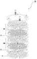
도 1은 흐르는 물에서 수중방전을 일으켜 살균수를 생성하는 살균수 생성 유닛(10)의 구성을 도시한 도면이다.1 is a view showing the configuration of the sterilizing
도 1에 도시된 바와 같이, 본 발명에 따른 살균수 생성 유닛(10)은, 한쌍의 전극판(2a, 2b)과 그 사이에 위치한 전극분리판(3)으로 이루어진 극판모듈(m), 한쌍의 전극판에 서로 다른 전극을 인가하여 양 극판 사이에서 수중방전을 일으키도록 전극을 인가하는 한쌍의 전극봉(4a, 4b) 및 이 한쌍의 전극봉을 수용하고 극판모듈(m)을 고정시키는 링형 프레임(5)을 포함하여 구성된다.As shown in FIG. 1, the sterilizing
전극판(2)의 내부에는 기다란 슬롯(21)이 복수개 형성되어 있으며, 이 슬롯을 통해 물이 통과하면서 수중방전을 통해 살균수가 생성된다. 슬롯의 폭(t)은 특별히 한정되지 않지만, 전극판의 강성과 물 통과 유량을 고려하여 인접한 슬롯 사이의 간격(s)과 동일하게 형성되는 것이 바람직하다.A plurality of
전극판(2)의 둘레에는 슬롯이 형성되지 않은 둘레부(22)가 형성되어 있으며, 이 둘레부에는 전극판에 전극을 인가하는 전극봉(4)이 관통되는 한쌍의 전극봉홀(23a, 23b)과, 극판모듈(m)의 고정을 위한 극판고정홈(24)이 형성되어 있다.A
한쌍의 전극봉홀(23a, 23b)의 크기는 서로 상이한데, 이는 극판모듈(m)의 한쌍의 전극판(2a, 2b)에 서로 다른 전극을 손쉽게 인가시키기 위한 구성이다. 예를 들면, 하나의 전극봉홀(23a)의 크기는 전극봉(4)의 외경과 실질적으로 동일한 크기로 형성되어 있어서 이 전극봉홀(23a)과 관통 접촉하는 전극봉을 통해 전극판에 전극이 인가된다.The sizes of the pair of
특히, 한쌍의 전극봉(23a, 23b)은 외부에 수나사부(41)가 형성된 나사인 것이 바람직하다. 즉, 전극봉에 나사 가공을하여 전극봉의 나사골 사이에 전극판이 위치하도록 전극판과 전극봉을 서로 맞물리게 함으로써 전극봉홀(23a)의 둘레를 따라 전극판과 전극봉이 서로 접촉하게 할 수 있다. 이를 통해, 전극봉과 전극판의 접촉 면적을 최대로 하여 수중 방전의 효율을 높일 수 있다.In particular, it is preferable that the pair of
한편, 다른 하나의 전극봉홀(23b)의 크기는 전극봉의 외경보다 충분히 더 큰 크기로 형성되므로 이 전극봉홀(23b)을 통해서는 전극봉에 인가된 전극이 전극판(4)에 전달되지 않는다. 따라서, 한쌍의 전극판(2a, 2b)을 적층할 때, 서로 다 른 크기를 갖는 한쌍의 전극봉홀(23a, 23b)이 서로 교대로 연통하도록 배치하면, 한쌍의 전극판에 서로 다른 전극이 인가될 수 있다.On the other hand, since the size of the
이와 같이, 전극판에 서로 다른 크기의 구멍을 가공함으로써 한쌍의 전극판에 서로 다른 전극을 손쉽게 인가시킬 수 있다.In this way, by processing holes of different sizes in the electrode plate, different electrodes can be easily applied to the pair of electrode plates.
전극판은 인체에 무해하며 내식성, 내산성, 내열성, 기계적 인장강도가 매우 뛰어난 티타늄을 재료로 하여 제조한 후, 백금, 이리듐, 팔라듐, 오스듐, 루테늄 등의 백금족 금속을 이용하여 코팅 또는 증착하여 제조된다. 이외에도, 일반 철판에 티타늄 증착을 한 후 상술한 백금족 소재를 이용하여 코팅 또는 증착하여 제조단가를 줄일 수 있다.The electrode plate is made of titanium, which is harmless to human body and has excellent corrosion resistance, acid resistance, heat resistance, and mechanical tensile strength, and is then coated or deposited using platinum group metals such as platinum, iridium, palladium, osdium, and ruthenium. do. In addition, after the titanium deposition on the general iron plate can be coated or deposited using the above-described platinum group material to reduce the manufacturing cost.
한쌍의 전극판(2a, 2b) 사이에는 이들 전극판을 전기적으로 이격시키기 위한 중공의 전극분리판(3)이 위치한다. 이 전극분리판(3)은 전극판을 통과하는 물의 흐름을 방해하지 않으면서 전극판들을 서로 전기적으로 절연시키는 구조를 갖는 것이 바람직하다. 이를 위해, 본 발명에 따른 전극분리판(3)은 중공의 형태를 가지고 있으며 그 둘레에는 한쌍의 전극봉홀과 연통하는 한쌍의 전극봉홈(31) 및 분리판고정홈(33)이 형성되어 있다. 전극봉홈(31)의 크기는 전극봉이 전극분리판에 접촉하지 않도록 전극봉의 외경보다 충분히 큰 크기로 형성되어 있다.Between the pair of
물이 극판모듈을 통과할 때 수압에 의해 한쌍의 전극판이 접촉되어 수중방전이 방해될 수 있으므로, 전극분리판은 전극판과의 접촉 면적을 증가시켜 절연 성능을 확보함과 동시에 물의 원활한 흐름을 방해해서는 안된다. 본 발명에 따른 전극분리판은 이와 같이 상충되는 요구 조건을 만족시키기 위해 한쌍의 전극봉홈(31)을 서로 연결시키는 기다란 띠 모양의 전극봉홈연결부(32)를 포함한다. 이 전극봉홈연결부의 폭은 물의 흐름을 방해하지 않기 위해, 슬롯의 폭(t) 또는 슬롯 사이의 간격(s)과 실질적으로 동일하거나 그보다 좁게 형성되는 것이 바람직하다. 아울러, 전극분리판은 분리판고정홈(33)을 서로 연결시키는 기다란 띠 모양의 고정홈연결부(34)를 더 포함할 수 있으며, 이 고정홈연결부(34)와 전극봉홈연결부(32)이 교차되는 영역에 환형의 중앙연결부(35)가 형성될 수 있다.When water passes through the pole plate module, a pair of electrode plates may be contacted by water pressure, which may interfere with underwater discharge. Therefore, the electrode separator plate increases the contact area with the electrode plate to secure insulation performance and prevent water from flowing smoothly. Should not. The electrode separator according to the present invention includes an elongated strip-shaped electrode
전극분리판을 사이에 두고, 한쌍의 전극판(2a, 2b)을 위치시켜 극판모듈(m)이 구성되는데, 여기서 한쌍의 전극판은 도 1에 도시된 바와 같이 내부에 형성된 슬롯이 서로 교차하도록 배치된다. 특히, 한쌍의 전극판이 교차 배치됨으로써 형성된 유로는 정방형인 것이 바람직하다. 한쌍의 전극판을 이와 같이 배치함으로써 물의 전기분해 성능이 월등히 증가되어 살균수의 생성 효율을 높일 수 있다.A pole plate module (m) is constructed by placing a pair of electrode plates (2a, 2b) with an electrode separator plate therebetween, wherein the pair of electrode plates has a slot formed therein as shown in FIG. Is placed. In particular, it is preferable that the flow path formed by crossing a pair of electrode plates is square. By arranging a pair of electrode plates in this way, the electrolytic performance of water is greatly increased, and the production efficiency of sterilizing water can be improved.
프레임(5)은 극판모듈(m)을 고정시키고, 전극봉(4)을 수용 및 지지한다. 프레임(5)은 내부에 중공(51)이 형성된 링형이며, 둘레에 전극봉수용부(52) 및 고정부(55)가 형성되어 있다. 전극봉수용부(52)에는 전극봉이 삽입되는 전극봉삽입홀(53)이 형성되어 있으며, 고정부(55)에는 극판모듈(m)을 프레임(5)에 고정시키기 위한 고정부재(54)가 삽입되는 고정부재홈(56)이 형성되어 있다. 전극봉(4)의 형상은 특별히 한정되지 않지만 삽입, 결합 및 분해가 용이한 나사 형태가 바람직하다.The frame 5 fixes the pole plate module m, and accommodates and supports the
도 2는 본 발명의 다른 바람직한 실시예에 따른 살균수 생성 유닛을 도시한 도면이다. 도 2에 도시된 바와 같이, 살균수 생성 유닛(10)은 복수개의 극판모 듈(m1, m2, ...)이 적층되어 구성될 수 있으며, 이 복수개의 극판모듈 사이에는 전극분리판(3)이 추가로 구비된다. 이와 같이, 복수개의 극판모듈을 적층시키고, 한쌍의 전극봉을 이용하여 각 전극판에 서로 다른 전극을 교대로 인가함으로써 살균수 생성 효율을 더욱 향상시킬 수 있다.2 is a view showing a sterilizing water generating unit according to another preferred embodiment of the present invention. As shown in FIG. 2, the sterilizing
또한, 복수개의 극판모듈을 적층시키지 않고, 극판모듈(m1) 아래에 하나의 전극판(2)을 위치시키고, 이 전극판(2)과 극판모듈(m1) 사이에 전극분리판을 위치시켜 3개의 전극판과 2개의 전극분리판으로 극판 모듈을 구성할 수도 있다.Further, without stacking a plurality of pole plate modules, one
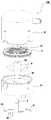
다음으로는 본 발명에 따른 살균수 생성 유닛(10)을 포함하는 살균수 생성 카트리지(100)에 대해 설명하기로 한다. 도 3 및 도 4에는 본 발명의 일 실시예에 따른 살균수 생성 카트리지(100)가 도시되어 있다.Next, the sterilizing
본 발명에 따른 살균수 생성 카트리지(100)는 입수부로부터 유입되는 공급수를 살균수로 전환하여 출수부를 통해 배출하는 장치이다. 즉, 이 카트리지를 이용하면 물 공급배관에 간단히 부착하여 살균수를 생성할 수 있다.The sterilizing
살균수 생성 카트리지(100)는 살균수 생성 유닛(10)과 이를 수용하는 케이스(7)를 포함하고, 케이스(7)는 분리와 조립이 용이하게 하부 케이스(71) 및 상부 케이스(72)를 포함하여 이루어진다.The sterilizing
살균수 생성 유닛(10)은 하부 케이스(71)에 형성된 안착부(718)에 안착된다. 따라서, 살균수 생성 카트리지(100)는 그 내부로 유입된 물이 반드시 전극판(4)의 슬롯을 통과하여 배출되는 구조로 이루어져 있다.The sterilizing
하부 케이스(71)의 하면(712)에는 입수부(711)가 구비되어 있고, 상부 케이스(72)의 측면(722)에는 출수부(721)가 구비되어 있다. 도 3 및 도 4에는 출수부(721)가 상부 케이스의 측면에 구비되어 있지만, 카트리지가 부착되는 장치의 연결 조건에 따라 출수부가 상면(724) 구비될 수 있다.The
이와 같이 입수부를 하측에 두고, 출수부를 상측에 두는 이유는 물의 전기분해 효율을 더욱 높이기 위함이다. 즉, 입수부가 상부에 있고, 출수부가 하부에 있다면 중력에 의해 물이 빠르게 살균수 생성 유닛(10)을 통과하게 되므로, 전기분해되는 물의 양이 적을 수 밖에 없다. 하지만, 물이 공급되는 입수부를 아래에 위치시키면, 물이 살균수 생성 유닛(10)을 통과하는 시간을 더 많이 확보할 수 있어서 살균수 생성 효율을 더욱 높일 수 있다.The reason why the inlet portion is placed below and the outlet portion is placed on the upper side is to further increase the electrolysis efficiency of water. That is, if the water inlet is in the upper portion, and the water outlet is in the lower portion, since water quickly passes through the sterilizing
하부 케이스(71)에는 살균수 생성 유닛(10)이 안착된다. 살균수 생성 유닛(10)은 하부 케이스 내부에 형성된 고정구(미도시)에 고정부재(54)를 삽입 고정함으로써 하부 케이스(71)에 고정될 수 있다.The
하부 케이스(71)에는 전극봉(4)과 전기적으로 접속가능한 접속단자(713)가 외부로 돌출형성되어 있다. 접속단자(713)의 내부에는 전극봉을 수용할 수 있는 접속공(715)이 형성되어, 이 접속공에 전극봉(4)을 삽입함으로써 접속단자(713)와 전극봉(4)이 전기적으로 연결된다. 따라서, 이 접속단자(713)에 전원을 연결시킴으로써 전극봉에 전극을 인가할 수 있다.The
하부 케이스(71)의 상단부(716)에는 링홈(717)이 형성되어 있으며, 링홈(717) 내부에 고무링(719)을 설치하여 하부 케이스(71)와 상부 케이스(72)가 서 로 결합될 때 카트리지 내부의 물이 외부로 새어나가지 않는다.A
하부 케이스(71)에는 상부 케이스(72)와의 결합을 위한 하부 결합부(714)가 둘레를 따라 복수개 형성된다. 그리고, 이 하부 결합부(714)와 대응되는 위치에, 상부 케이스(72)의 둘레를 따라 상부 결합부(724)가 형성되어 있다. 상부 결합부와 하부 결합부에 나사 또는 핀과 같은 결합부재(73)를 삽입함으로써 이들은 손쉽게 결합된다. 이와 같이, 케이스(7)를 상부 케이스와 하부 케이스를 분리하여 형성함으로써, 케이스(7) 내에 수용된 살균수 생성 유닛의 유지 보수가 간편히 이루어질 수 있다.The
하부 케이스(71)의 입수부(711)로부터 공급되는 물(공급수)이 살균수 생성 유닛(10)의 전극판(4)의 전면적에 걸쳐 통과하도록 안내하는 유로가이드부재(6)가 살균수 생성 유닛(10)과 상기 하부케이스의 입수부(711) 사이에 구비될 수 있다. 이 유로가이드부재(6)는 원판 모양으로 이루어져 있으며 그 내부에 물이 통과하는 안내공(61)이 복수개 형성되어 있다. 그리고, 유로가이드부재(6)의 양측에는 전극봉(4)이 접촉없이 통과하도록 하는 전극봉통과부(62)가 형성되어 있다. 이 전극봉통과부는(62) 유로가이드부재(6)로부터 상방으로 연장형성되어 살균수 생성 유닛(10)이 이 유로가이드부재(6)와 조립될 때 이들 사이에 물이 이동하는 공간이 형성된다.The
전극봉(4)은 전극봉통과부(62)의 전극봉안내홀(63)을 통과하여 하부 케이스(71)의 접속단자(713)와 전기적으로 접속된다. 전극봉안내홀(63)의 크기는 전극봉의 외경보다 충분히 큰 크기로 형성되므로 전극봉은 유로가이드부재(6)와 접촉하 지 않는다.The
한편, 유로가이드부재(6)의 내부에 형성된 안내공(61)은 유로가이드부재(6)의 중심에서 멀어질수록 그 크기가 점점 커지는 것이 바람직하다. 일반적으로, 입수부(711)의 위치는 하부 케이스(71)의 실질적으로 중앙인 위치에 형성되므로, 극판모듈(m)을 통과하는 물이 전극판의 중앙으로 쏠리기 쉽다. 이러한 현상을 방지하기 위해, 안내공(61)의 크기는 중앙에서 멀어질수록 점점 커지도록 형성되는 것이 바람직하다. 따라서, 본 발명에 따른 유로가이드부재(6)를 통해 살균수 생성 카트리지에 유입된 물이 극판모듈(m)의 전면적에 걸쳐 통과하도록 할 수 있다.On the other hand, the
살균수 생성 유닛(10)의 프레임(5)에는 초음파진동자(55)가 고정 설치될 수 있다. 이 초음파진동자(55)는 물의 전기분해시 전극판에 형성되는 스케일을 물리적으로 제거하거나 생성을 방지하기 위해 설치된다. 따라서, 초음파진동자(55)의 설치 위치는 반드시 프레임(5)에 한정되지 않으며, 초음파진동자(55)에 의한 물리적 진동이 전극판에 전달될 수 있는 곳이라면 카트리지 내부의 어느 곳이라도 가능하다.The
이 밖에도 살균수 생성 카트리지 외부에 화학적 세정액을 투입하는 별도의 주입장치(도 7 참조)를 부착하여 살균수 생성 카트리지 내부로 세정액을 투입함으로써 전극판에 침작된 스케일을 화학적으로 제거할 수 있다.In addition, by attaching a separate injection device (see FIG. 7) injecting a chemical cleaning solution to the outside of the sterilizing water generating cartridge, by introducing the cleaning solution into the sterilizing water generating cartridge, the scale deposited on the electrode plate may be chemically removed.
도 5 및 도 6은 본 발명의 다른 바람직한 실시예에 따른 살균수 생성 카트리지(100)를 나타낸 도면이다. 이 살균수 생성 카트리지에는 살균수의 살균 성능을 더욱 향상시키기 위해 자외선 조사에 의한 살균 기능을 갖는 UV LED(8)가 설치된 다. 이 UV LED(8)는 케이스(7) 내부에 어느 곳이라도 부착 가능하지만, 케이스(7)를 분해하지 않고서도 케이스(7) 내부로 자외선을 조사할 수 있도록 다음과 같이 설치될 수 있다.5 and 6 are views showing the sterilizing
UV LED(8)는 기판(81)에 설치되어 있으며, 이 기판(81)을 하부 케이스(71)의 하면(712)에 부착하여 케이스(7)를 분해하지 않고서도 손쉽게 카트리지에 탈부착할 수 있다. 즉, 하부 케이스(71)에는 UV LED(8)를 수용하는 LED 하우징(73)이 형성되어 있어서, 기판(81)이 하부 케이스(71)의 하면(712)에 부착될 때 UV LED(8)는 LED 하우징(73) 내부에 수용된다.The
극판모듈(m) 및 유로가이드부재(6)에는 LED 하우징(73)이 관통되는 중심공(24, 64)이 형성되어 있다. 따라서, LED 하우징(73)의 끝단은 살균수 생성 유닛(10)과 유로가이드부재(6)가 하부 케이스에 안착될 때, 극판모듈(m) 위로 돌출 배치된다. 수중방전을 통해 생성된 살균수에 UV LED(8)를 통해 자외선을 조사함으로써 살균수의 살균 성능을 배가할 수 있다.
한편, UV LED(8)는 상술한 LED 하우징(73)에 수용되지 않고 직접 케이스 내부에 설치될 수 있다. 도 6에 도시된 바와 같이, UV LED(8)는 극판모듈(m)의 중심공(24)에 직접 삽입 설치되고, 중심공(24)과 UV LED(8) 사이에 밀봉부재(732)를 개재시켜 UV LED(8) 외주변을 밀폐시킬 수 있다.Meanwhile, the
기판(81)에는 전원 공급용 접속핀(82) 및 하부 케이스(71)의 접속단자(713)가 관통접속되는 접속구(83)가 형성되어 있다. 따라서, 접속핀(82)에 전원을 연결함으로써 전극봉(4) 및 UV LED(8)에 전원을 손쉽게 공급할 수 있다.The
아울러, 본 발명에 있어서 한쌍의 전극판(2a, 2b), UV LED(8), 초음파진동자(55)는 상술한 접속핀(82)과 연결된 제어부(미도시)에 의해 전원의 공급 및 제어가 이루어질 수 있다.In addition, in the present invention, the pair of
한편, UV LED(8)가 살균수 생성 카트리지에 설치될 경우에는, 입수부(711)가 하부 케이스에 편심되게 위치될 수 있다. 이 경우, 케이스(7) 내부에서 극판모듈(m)로의 물의 원활한 흐름을 유도하기 위해 하부 케이스(71)의 내부 바닥면에는 유로안내홈(731)이 형성되어 있다. 따라서, 입수부(711)를 통과한 물이 유로안내홈(731)을 거쳐 지나가기 때문에, 입수부(711)의 편심 효과를 줄일 수 있는 이점이 있다.On the other hand, when the
본 발명에 따른 살균수 생성 카트리지를 통해 살균수가 생성되는 과정을 간략히 설명하면 다음과 같다.The process of generating sterilizing water through the sterilizing water generating cartridge according to the present invention will be described briefly as follows.
입수부(711)로부터 공급수가 케이스(7) 내부로 유입되면, 유입된 물은 한쌍의 전극판(2a, 2b)이 포함된 극판모듈(m)에서 수중방전이 이루어지고, 이를 통해 물분자(H20)가 수소원자(H)와 산소원자(O)의 이온상태로 분해되어 기포가 발생하고 수중확산이 시작된다. 이 때, 산소원자는 다른 산소원자와 결합하고자 하는 성질로 O2의 산소분자가 생성되고 수소원자는 음이온전자를 방출시키면서 수소이온(H+)으로 되며, 산소분자는 주변의 음이온을 흡수하여 O2-로 변화된다. 생성된 H+와 O2-가 주변의 물분자와 반응함에 따라 수산기(OH-)를 비롯하여 H2O2 및 O3가 생성되고, 이 때 생성된 수산기는 분자 성질상 매우 불안정해서 물속에 있는 세균류의 세포막에 있는 H+와 결합하고자 하며 H+를 빼앗긴 세포막은 파괴되어 살균되고 물분자로 다시 환원된다. 이 때, 수산기와 함께 생성되는 H2O2 및 O3는 바로 증발된다.When the supply water from the
그리고, 공급수의 수중에 함유된 미량의 염소성분과 물분자와 반응함에 의해 살균기능을 갖는 차아염소산이 생성되어 살균작용을 하게 된다.And, by reacting with a trace amount of chlorine component and water molecules contained in the feed water water, hypochlorous acid having a sterilizing function is generated and sterilizing action.
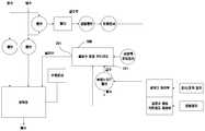
다음으로는, 본 발명에 따른 살균수 생성 카트리지를 포함하는 살균 세탁기에 대해 설명하기로 한다. 도 7은 본 발명에 따른 살균수 생성 카트리지가 부착된 살균 세탁기의 작동 흐름도를 나타낸 도면이다.Next, a sterilizing washing machine including the sterilizing water generating cartridge according to the present invention will be described. 7 is a view showing the operation of the sterilizing washing machine with a sterilizing water generating cartridge according to the present invention.
본 발명에 따른 살균수 생성 카트리지(100)에 유입되는 물은 다음과 같은 과정을 통해 공급된다. 배관으로부터 공급되는 온수 및/또는 냉수가 밸브를 통해 선택적으로 혼합되고 밸브를 통과한 물로부터 필터를 통해 불순물이 제거된다. 필터를 통과한 물은 감압밸브에 의해 압력이 조절되고, 유량센서를 이용하여 살균수 생성 카트리지(100)에 공급되는 유량이 조절된다.Water flowing into the sterilizing
상술한 바와 같이 구성된 살균 세탁기의 급수부를 통해, 물은 입수부(711)를 거쳐 살균수 카트리지(100) 내부로 유입되며, 수중방전에 의해 생성된 살균수는 출수부(721)를 통해 살균 세탁기의 세탁조로 공급되어 세탁물의 행굼시에 사용될 수 있다.Through the water supply unit of the sterilizing washing machine configured as described above, water is introduced into the sterilizing
특히, 살균 세탁기의 급수부와 상기 살균수 생성 카트리지의 입수부 사이에 는 솔레노이드 밸브가 구비될수 있다. 이 솔레노이드 밸브는 살균수 생성 카트리지로의 급수 및 배수를 제어하기 위한 3방향 밸브로서, 살균수 생성 카트리지가 작동될 때에는 살균수 생성 카트리지 내부로 물이 공급되도록 개폐 방향이 조절되고, 작동이 중단될 때에는 살균수 생성 카트리지 내부의 물 또는 살균수가 배수되도록 개폐 방향이 조절된다.In particular, a solenoid valve may be provided between the water supply part of the sterilizing washing machine and the water supply part of the sterilizing water generating cartridge. This solenoid valve is a three-way valve for controlling the water supply and drainage to the sterilizing water generating cartridge. When the sterilizing water generating cartridge is operated, the opening and closing direction is adjusted so that water is supplied into the sterilizing water generating cartridge and the operation is stopped. At this time, the opening and closing direction is adjusted to drain the water or the sterilizing water inside the sterilizing water generating cartridge.
이와 같이 카트리지 내부의 물을 배출함으로써 살균수 생성 카트리지의 동파를 방지할 수 있다 또한, 배수 과정에서 카트리지 내부에 있는 살균수는 배수관(미도시)으로 배출되어 배수관 내에 있는 세균, 곰팡이, 물때 등을 제거하는 추가적인 효과를 얻을 수 있다.In this way, by discharging the water inside the cartridge, it is possible to prevent freezing of the sterilizing water generating cartridge. In addition, during the draining process, the sterilizing water inside the cartridge is discharged to a drain pipe (not shown) to remove bacteria, mold, and scale in the drain pipe. The additional effect of removing it can be obtained.
한편, 살균수 생성 카트리지에는 세정액 주입장치가 연결될 수 있다. 세정액 주입장치에는 세정액(예를 들면 식초와 같은 산성수)이 담겨 있으며, 이 세정액을 카트리지 내부로 주입하여 수중방전 과정에서 전극판에 생성된 스케일을 화학적으로 제거할 수 있다. 이 세정액 주입장치는 상술한 솔레노이드 밸브에 의해 물의 공급이 중단된 상태에서 카트리지 내부로 세정액을 주입하여 스케일을 제거하도록 작동되며, 전극판으로부터 제거된 스케일 찌꺼기는 상술한 배수 과정을 통해 세탁기 외부로 빠져 나가게 된다.On the other hand, the cleaning liquid injecting device may be connected to the sterilizing water generating cartridge. The cleaning solution injector contains a cleaning solution (for example, acidic water such as vinegar), and the cleaning solution may be injected into the cartridge to chemically remove the scale generated in the electrode plate during the underwater discharge process. The cleaning liquid injector is operated to remove the scale by injecting the cleaning liquid into the cartridge while the water supply is stopped by the above-described solenoid valve. Will go out.
살균수 생성 카트리지 및 세탁기의 제어는 도 7에 도시된 각각의 제어부에 의해 구현될 수 있으며 이에 대한 구체적인 설명은 생략하기로 한다.Control of the sterilizing water generating cartridge and the washing machine may be implemented by each control unit shown in FIG. 7, and a detailed description thereof will be omitted.
도 1은 본 발명의 일 실시예에 따른 살균수 생성 유닛의 분해 사시도이다.1 is an exploded perspective view of a sterilizing water generating unit according to an embodiment of the present invention.
도 2는 본 발명의 다른 실시예에 따른 살균수 생성 유닛의 분해 사시도이다.2 is an exploded perspective view of a sterilizing water generating unit according to another embodiment of the present invention.
도 3은 본 발명의 일 실시예에 따른 살균수 생성 카트리지의 분해 사시도이다.3 is an exploded perspective view of the sterilizing water generating cartridge according to an embodiment of the present invention.
도 4는 본 발명의 일 실시예에 따른 살균수 생성 카트리지의 조립 단면도이다.4 is an assembled cross-sectional view of the sterilizing water generating cartridge according to an embodiment of the present invention.
도 5는 본 발명의 다른 실시예에 따른 살균수 생성 카트리지의 분해 사시도이다.5 is an exploded perspective view of a sterilizing water generating cartridge according to another embodiment of the present invention.
도 6는 본 발명의 다른 실시예에 따른 살균수 생성 카트리지의 조립 단면도이다.6 is an assembled cross-sectional view of the sterilizing water generating cartridge according to another embodiment of the present invention.
도 7은 본 발명에 따른 살균수 생성 카트리지가 부착된 살균 세탁기의 작동 흐름도를 나타낸 도면이다.7 is a view showing the operation of the sterilizing washing machine with a sterilizing water generating cartridge according to the present invention.
Claims (22)
Translated fromKoreanPriority Applications (4)
| Application Number | Priority Date | Filing Date | Title |
|---|---|---|---|
| KR1020090018365AKR100927445B1 (en) | 2009-03-04 | 2009-03-04 | Sterilizing water generating unit, sterilizing water generating cartridge and sterilizing washing machine comprising the same |
| JP2010044090AJP4902757B2 (en) | 2009-03-04 | 2010-03-01 | Sterilized water generating unit, sterilized water generating cartridge including the same, and sterilized washing machine |
| US12/714,934US8540860B2 (en) | 2009-03-04 | 2010-03-01 | Unit for producing sterilized water, cartridge comprising the unit and washing machine comprising the cartridge |
| CN2010101285132ACN101823781B (en) | 2009-03-04 | 2010-03-03 | Unit for producing sterilized water, cartridge comprising the unit and washing machine comprising the cartridge |
Applications Claiming Priority (1)
| Application Number | Priority Date | Filing Date | Title |
|---|---|---|---|
| KR1020090018365AKR100927445B1 (en) | 2009-03-04 | 2009-03-04 | Sterilizing water generating unit, sterilizing water generating cartridge and sterilizing washing machine comprising the same |
Publications (1)
| Publication Number | Publication Date |
|---|---|
| KR100927445B1true KR100927445B1 (en) | 2009-11-19 |
Family
ID=41605181
Family Applications (1)
| Application Number | Title | Priority Date | Filing Date |
|---|---|---|---|
| KR1020090018365AExpired - Fee RelatedKR100927445B1 (en) | 2009-03-04 | 2009-03-04 | Sterilizing water generating unit, sterilizing water generating cartridge and sterilizing washing machine comprising the same |
Country Status (4)
| Country | Link |
|---|---|
| US (1) | US8540860B2 (en) |
| JP (1) | JP4902757B2 (en) |
| KR (1) | KR100927445B1 (en) |
| CN (1) | CN101823781B (en) |
Cited By (21)
| Publication number | Priority date | Publication date | Assignee | Title |
|---|---|---|---|---|
| KR101015621B1 (en) | 2010-06-09 | 2011-02-21 | 김용진 | Instant sterilization disinfectant generator |
| WO2011065794A3 (en)* | 2009-11-30 | 2011-09-15 | (주)경우이앤씨 | Flow-through electrolysis apparatus, and injection device using same |
| KR101308657B1 (en)* | 2011-05-19 | 2013-09-13 | 주식회사 교원 | Water sterilizer |
| KR20140001543A (en)* | 2012-06-27 | 2014-01-07 | 코웨이 주식회사 | A central emission type water sterilizer |
| KR20140031567A (en)* | 2012-09-04 | 2014-03-13 | 코웨이 주식회사 | Water sterilizing module comprising metal lath type electrodes and water sterilizer comprising the same |
| KR20140087350A (en)* | 2012-12-28 | 2014-07-09 | 코웨이 주식회사 | Cap of water bottle and humidifier having the same |
| KR101433123B1 (en) | 2012-08-28 | 2014-08-25 | 주식회사 그렌텍 | Cartridge for creating sterilized water having tilted electrode plate |
| KR101433124B1 (en)* | 2012-08-29 | 2014-08-26 | (주)그렌텍 | Cartridge for creating sterilized water having hloe for inserting and taking out water in one direction |
| KR101433128B1 (en)* | 2012-10-12 | 2014-08-26 | (주)그렌텍 | Cartridge for creating sterilized water having particle under electrode plate |
| KR101433125B1 (en)* | 2012-10-12 | 2014-08-26 | (주)그렌텍 | A Unit for creating sterilized water of easy combination with base member and bathtub for foot using the same |
| KR101515153B1 (en)* | 2014-03-07 | 2015-04-24 | 주식회사 그렌텍 | A airwasher of sterilized water having transparent window |
| WO2016052938A3 (en)* | 2014-09-30 | 2016-05-26 | 주식회사 뉴워터텍 | Electrolytic water-treatment device |
| KR101768119B1 (en) | 2017-02-02 | 2017-08-14 | 주식회사 뉴워터텍 | Electrolytic water treatment system |
| KR20170122524A (en)* | 2016-04-27 | 2017-11-06 | 방춘영 | Apparatus for making hydrogen water |
| KR20180040019A (en)* | 2016-10-11 | 2018-04-19 | 주식회사 스팀보이 | Sterilization humidifier with electrolysis module |
| KR101867370B1 (en)* | 2017-04-17 | 2018-06-15 | 주식회사 이온팜스 | Portable Type Hydrogen Water Generator |
| KR20180065618A (en)* | 2016-12-08 | 2018-06-18 | 이태섭 | Hydrogen water generator |
| KR101918708B1 (en)* | 2017-04-18 | 2018-11-15 | 주식회사 마이크로필터 | Unit for creating sterilized water |
| KR20180128841A (en)* | 2017-05-24 | 2018-12-04 | 서울대학교산학협력단 | Capillary-based electrolysis cell |
| KR20190052191A (en)* | 2017-11-06 | 2019-05-16 | 주식회사 그린온 | Air Cleaner Having Electrolysis Reactor |
| KR20220001230U (en) | 2020-11-24 | 2022-05-31 | 주식회사 에코수 | Hydrogen Water Generating Apparatus for Disintectant Spray |
Families Citing this family (25)
| Publication number | Priority date | Publication date | Assignee | Title |
|---|---|---|---|---|
| TW201137152A (en)* | 2010-04-26 | 2011-11-01 | Hon Hai Prec Ind Co Ltd | Workpiece support for coating |
| KR200462514Y1 (en) | 2010-09-28 | 2012-09-13 | 주식회사 에코프롬 | Portable water sterilizer utilizing low salinity solution or fresh water |
| KR200464612Y1 (en)* | 2010-11-23 | 2013-01-11 | 주식회사 에코프롬 | Apparatus for sterilizer running water |
| KR101182659B1 (en) | 2010-11-23 | 2012-09-14 | 주식회사 에코프롬 | Portable water sterilizer with partition structure |
| WO2013064154A1 (en)* | 2011-11-02 | 2013-05-10 | Syddansk Universitet | Toroidal-shaped treatment device for disinfecting a fluid such as air or water |
| JP4999030B1 (en)* | 2011-11-28 | 2012-08-15 | イノベーティブ・デザイン&テクノロジー株式会社 | Scale removal device electrode structure |
| EP2788291A1 (en)* | 2011-12-09 | 2014-10-15 | MAG Aerospace Industries, LLC | Inline uv led water disinfection and heating |
| KR101317169B1 (en) | 2012-05-07 | 2013-10-15 | 리치코 주식회사 | The washer-sterilizer with detachable electrolysis cell |
| CN104925915A (en)* | 2014-03-20 | 2015-09-23 | 黄海成 | Generation method of ecological water |
| JP2016175025A (en)* | 2015-03-20 | 2016-10-06 | 旭化成株式会社 | Cell for sterilization module, and sterilization module |
| KR101669185B1 (en)* | 2015-08-24 | 2016-11-10 | 한국식품연구원 | Plasma sterilizer apparatus for pipe |
| US10180248B2 (en) | 2015-09-02 | 2019-01-15 | ProPhotonix Limited | LED lamp with sensing capabilities |
| RU2601461C1 (en)* | 2015-09-10 | 2016-11-10 | Владимир Григорьевич Оленников | Method of industrial and waste waters cleaning and disinfection |
| US20180193816A1 (en)* | 2016-08-23 | 2018-07-12 | Industrial Heat, Llc | Designs of exothermic reactors |
| WO2018131983A1 (en)* | 2017-01-16 | 2018-07-19 | 서울바이오시스주식회사 | Water purifier |
| EP3415069A1 (en)* | 2017-06-16 | 2018-12-19 | Sanhua AWECO Appliance Systems GmbH | Plasma activated water for disinfecting home appliances |
| CN107130395A (en)* | 2017-06-26 | 2017-09-05 | 柯丹 | A kind of cleaning method of sterilizing washing machine and clothes washing method and washing machine |
| CN107374547B (en)* | 2017-08-08 | 2020-07-14 | 佛山市顺德区美的洗涤电器制造有限公司 | Sterilization device and household appliance |
| CN110453243A (en)* | 2018-05-08 | 2019-11-15 | 罗民雄 | A kind of general electrolyte electrode modular method |
| CN109629174A (en)* | 2019-01-01 | 2019-04-16 | 佛山市顺德区硕美工业设计有限公司 | The interior without phosphorus decomposition washing machine of life |
| TWI707827B (en)* | 2019-12-06 | 2020-10-21 | 國立臺北科技大學 | Uv-light liquid disinfection device |
| CN111472142B (en)* | 2020-06-02 | 2024-06-28 | 慈溪市天泉电器科技有限公司 | Mixed air type sterilizing washing machine barrel |
| US12252419B2 (en)* | 2020-07-10 | 2025-03-18 | Thomas G. Pownall | Trans-channel reaction cell and method of use |
| CN114468926A (en)* | 2020-10-23 | 2022-05-13 | 珠海格力电器股份有限公司 | Electrolytic component and electrolytic device of dish washing machine and dish washing machine |
| KR102534771B1 (en)* | 2021-12-13 | 2023-05-26 | 주식회사 그린온 | Vaporizer for Sterilization and Deinsectization |
Citations (2)
| Publication number | Priority date | Publication date | Assignee | Title |
|---|---|---|---|---|
| KR200287646Y1 (en)* | 2002-06-10 | 2002-08-30 | (주)크로바 환경 | a discomposition Vessel for a waste water disposal Plant |
| KR100691380B1 (en)* | 2005-09-23 | 2007-03-09 | 박호원 | Electrolytic Sterilization Water Purifier Filter Module |
Family Cites Families (21)
| Publication number | Priority date | Publication date | Assignee | Title |
|---|---|---|---|---|
| CN1099379C (en)* | 1994-05-31 | 2003-01-22 | 东陶机器株式会社 | Electrolysis apparatus and method for chloride ion-containing flowing water |
| JPH0871565A (en)* | 1994-09-08 | 1996-03-19 | Tokico Ltd | Electrolyzed water generator |
| US5681457A (en)* | 1995-10-10 | 1997-10-28 | Mahoney; Robert F. | Electrodynamic fluid treatment system |
| JPH10146588A (en)* | 1996-09-18 | 1998-06-02 | Konica Corp | Apparatus and method for water treatment |
| CN2285770Y (en)* | 1997-01-21 | 1998-07-08 | 上海城市污染控制工程研究中心 | Sterilizing and alga killing device for treatment of water |
| JP2000093691A (en)* | 1998-07-24 | 2000-04-04 | Mitsubishi Electric Corp | Washing machine with sterilization function by electric field |
| JP2000140849A (en)* | 1998-11-09 | 2000-05-23 | Shikishima Kiki Kk | Electrochemical water treating device and method |
| IL130177A (en)* | 1999-05-27 | 2001-01-28 | Yissum Res Dev Co | Electro-flocculation process and apparatus |
| CN1289726A (en)* | 1999-09-28 | 2001-04-04 | 吕芳钟 | Packed bed electrochemical water treatment device and method |
| JP2003024943A (en)* | 2001-07-11 | 2003-01-28 | Sanyo Electric Co Ltd | Water treatment apparatus |
| JP4930912B2 (en)* | 2002-05-27 | 2012-05-16 | 独立行政法人科学技術振興機構 | Plasma sterilizer |
| JP4226387B2 (en)* | 2002-07-29 | 2009-02-18 | 日本テクノ株式会社 | Method for producing active, antiseptic water |
| EP1670721A1 (en)* | 2003-07-30 | 2006-06-21 | Anderson H. Kim | Ionized-water supplying apparatus using in-water plasma discharging |
| JP2006095497A (en)* | 2004-09-30 | 2006-04-13 | Sharp Corp | Metal ion elution unit and equipment equipped with the same |
| ATE486046T1 (en)* | 2006-02-17 | 2010-11-15 | Actides Gmbh | METHOD FOR PRODUCING A DISINFECTANT BY ELECTROCHEMICAL ACTIVATION (ECA) OF WATER |
| US20070272550A1 (en)* | 2006-05-24 | 2007-11-29 | Advanced Desalination Inc. | Total solution for water treatments |
| JP2010530794A (en)* | 2007-02-26 | 2010-09-16 | ドルキー コリア,リミテッド | Method for producing medical sterilized physiological saline containing low concentration residual chlorine |
| JP5133592B2 (en)* | 2007-05-09 | 2013-01-30 | 日科ミクロン株式会社 | Ozone water generator |
| JP2008307524A (en)* | 2007-05-14 | 2008-12-25 | Sanyo Electric Co Ltd | Water treatment device |
| CN101679016A (en)* | 2007-11-09 | 2010-03-24 | 株式会社盘浦流通 | Power saving type safe drinking water discharge device |
| JP4848460B2 (en)* | 2008-02-14 | 2011-12-28 | 三菱重工業株式会社 | Gas turbine blade regeneration method and gas turbine blade regeneration device |
- 2009
- 2009-03-04KRKR1020090018365Apatent/KR100927445B1/ennot_activeExpired - Fee Related
- 2010
- 2010-03-01JPJP2010044090Apatent/JP4902757B2/ennot_activeExpired - Fee Related
- 2010-03-01USUS12/714,934patent/US8540860B2/enactiveActive
- 2010-03-03CNCN2010101285132Apatent/CN101823781B/enactiveActive
Patent Citations (2)
| Publication number | Priority date | Publication date | Assignee | Title |
|---|---|---|---|---|
| KR200287646Y1 (en)* | 2002-06-10 | 2002-08-30 | (주)크로바 환경 | a discomposition Vessel for a waste water disposal Plant |
| KR100691380B1 (en)* | 2005-09-23 | 2007-03-09 | 박호원 | Electrolytic Sterilization Water Purifier Filter Module |
Cited By (29)
| Publication number | Priority date | Publication date | Assignee | Title |
|---|---|---|---|---|
| WO2011065794A3 (en)* | 2009-11-30 | 2011-09-15 | (주)경우이앤씨 | Flow-through electrolysis apparatus, and injection device using same |
| KR101215602B1 (en) | 2009-11-30 | 2012-12-26 | (주)경우이앤씨 | Electrolysis Device Of Flowing Liquid Through And Sprayer Using The Same |
| KR101015621B1 (en) | 2010-06-09 | 2011-02-21 | 김용진 | Instant sterilization disinfectant generator |
| KR101308657B1 (en)* | 2011-05-19 | 2013-09-13 | 주식회사 교원 | Water sterilizer |
| KR20140001543A (en)* | 2012-06-27 | 2014-01-07 | 코웨이 주식회사 | A central emission type water sterilizer |
| KR101946560B1 (en)* | 2012-06-27 | 2019-02-11 | 코웨이 주식회사 | A central emission type water sterilizer |
| KR101433123B1 (en) | 2012-08-28 | 2014-08-25 | 주식회사 그렌텍 | Cartridge for creating sterilized water having tilted electrode plate |
| KR101433124B1 (en)* | 2012-08-29 | 2014-08-26 | (주)그렌텍 | Cartridge for creating sterilized water having hloe for inserting and taking out water in one direction |
| KR20140031567A (en)* | 2012-09-04 | 2014-03-13 | 코웨이 주식회사 | Water sterilizing module comprising metal lath type electrodes and water sterilizer comprising the same |
| KR101939749B1 (en)* | 2012-09-04 | 2019-04-11 | 코웨이 주식회사 | Water sterilizing module comprising metal lath type electrodes and water sterilizer comprising the same |
| KR101433128B1 (en)* | 2012-10-12 | 2014-08-26 | (주)그렌텍 | Cartridge for creating sterilized water having particle under electrode plate |
| KR101433125B1 (en)* | 2012-10-12 | 2014-08-26 | (주)그렌텍 | A Unit for creating sterilized water of easy combination with base member and bathtub for foot using the same |
| KR20140087350A (en)* | 2012-12-28 | 2014-07-09 | 코웨이 주식회사 | Cap of water bottle and humidifier having the same |
| KR102010979B1 (en)* | 2012-12-28 | 2019-08-14 | 웅진코웨이 주식회사 | Cap of water bottle and humidifier having the same |
| KR101515153B1 (en)* | 2014-03-07 | 2015-04-24 | 주식회사 그렌텍 | A airwasher of sterilized water having transparent window |
| WO2016052938A3 (en)* | 2014-09-30 | 2016-05-26 | 주식회사 뉴워터텍 | Electrolytic water-treatment device |
| KR20170122524A (en)* | 2016-04-27 | 2017-11-06 | 방춘영 | Apparatus for making hydrogen water |
| KR101892672B1 (en)* | 2016-04-27 | 2018-08-28 | 방춘영 | Apparatus for making hydrogen water |
| KR101865574B1 (en)* | 2016-10-11 | 2018-06-08 | (주)스팀보이 | Sterilization humidifier with electrolysis module |
| KR20180040019A (en)* | 2016-10-11 | 2018-04-19 | 주식회사 스팀보이 | Sterilization humidifier with electrolysis module |
| KR20180065618A (en)* | 2016-12-08 | 2018-06-18 | 이태섭 | Hydrogen water generator |
| KR101768119B1 (en) | 2017-02-02 | 2017-08-14 | 주식회사 뉴워터텍 | Electrolytic water treatment system |
| KR101867370B1 (en)* | 2017-04-17 | 2018-06-15 | 주식회사 이온팜스 | Portable Type Hydrogen Water Generator |
| KR101918708B1 (en)* | 2017-04-18 | 2018-11-15 | 주식회사 마이크로필터 | Unit for creating sterilized water |
| KR20180128841A (en)* | 2017-05-24 | 2018-12-04 | 서울대학교산학협력단 | Capillary-based electrolysis cell |
| KR102123631B1 (en)* | 2017-05-24 | 2020-06-17 | 서울대학교산학협력단 | Capillary-based electrolysis cell |
| KR20190052191A (en)* | 2017-11-06 | 2019-05-16 | 주식회사 그린온 | Air Cleaner Having Electrolysis Reactor |
| KR102002318B1 (en)* | 2017-11-06 | 2019-10-02 | 주식회사 그린온 | Air Cleaner Having Electrolysis Reactor |
| KR20220001230U (en) | 2020-11-24 | 2022-05-31 | 주식회사 에코수 | Hydrogen Water Generating Apparatus for Disintectant Spray |
Also Published As
| Publication number | Publication date |
|---|---|
| JP4902757B2 (en) | 2012-03-21 |
| US8540860B2 (en) | 2013-09-24 |
| CN101823781B (en) | 2012-06-20 |
| US20100224483A1 (en) | 2010-09-09 |
| JP2010201421A (en) | 2010-09-16 |
| CN101823781A (en) | 2010-09-08 |
Similar Documents
| Publication | Publication Date | Title |
|---|---|---|
| KR100927445B1 (en) | Sterilizing water generating unit, sterilizing water generating cartridge and sterilizing washing machine comprising the same | |
| US10464830B2 (en) | Electrolytic liquid generating device, liquid modifying device provided with electrolytic liquid generating device, and electric apparatus using electrolytic liquid generated by means of electrolytic liquid generating device | |
| RU2494971C2 (en) | Installation for water softening by reverse osmosis | |
| CN105288761B (en) | Combined system of single-station RO device and hemodialysis device | |
| JP2002532236A (en) | Microbial control of point-of-use drinking water sources | |
| KR101080227B1 (en) | Portable beauty water sterilizer | |
| KR20080101623A (en) | Automatic cleaning device of electrolysis tank | |
| KR101433125B1 (en) | A Unit for creating sterilized water of easy combination with base member and bathtub for foot using the same | |
| KR100958677B1 (en) | High efficient un-divided electrochemical cell and apparatus for manufacturing of chlorine dioxide using it | |
| JP5648867B2 (en) | Sterilized water generating cartridge with one-way water inlet / outlet | |
| KR100634760B1 (en) | Sterile Oxidized Water Production Equipment Using Overpotential Electrode | |
| KR101739123B1 (en) | A cartridge for creating sterilized water having bypass | |
| CN201620057U (en) | A drinking water treatment device | |
| KR101544377B1 (en) | A sterilizing water producing device and a bidet | |
| KR20140047373A (en) | Unit for creating sterilized water having electrode plate support bar for maintaining distance between electrode plates | |
| KR20180117236A (en) | Unit for creating sterilized water | |
| KR101701106B1 (en) | Electrolytic cell of ion water purifier employing thesame | |
| JP2003088737A (en) | Ozone water production apparatus | |
| KR101433128B1 (en) | Cartridge for creating sterilized water having particle under electrode plate | |
| KR102542172B1 (en) | Disinfection water supply apparatus | |
| JP3132048U (en) | Electrolyzed water generator | |
| KR101433123B1 (en) | Cartridge for creating sterilized water having tilted electrode plate | |
| KR101880977B1 (en) | Complex device for producing hydrogen water and sterilizing water | |
| KR20110114949A (en) | Water treatment device to separate the cluster of water | |
| KR100839315B1 (en) | Ultrasonic Cleaner with Sterilization |
Legal Events
| Date | Code | Title | Description |
|---|---|---|---|
| A201 | Request for examination | ||
| PA0109 | Patent application | St.27 status event code:A-0-1-A10-A12-nap-PA0109 | |
| PA0201 | Request for examination | St.27 status event code:A-1-2-D10-D11-exm-PA0201 | |
| A302 | Request for accelerated examination | ||
| PA0302 | Request for accelerated examination | St.27 status event code:A-1-2-D10-D17-exm-PA0302 St.27 status event code:A-1-2-D10-D16-exm-PA0302 | |
| E902 | Notification of reason for refusal | ||
| PE0902 | Notice of grounds for rejection | St.27 status event code:A-1-2-D10-D21-exm-PE0902 | |
| N231 | Notification of change of applicant | ||
| PN2301 | Change of applicant | St.27 status event code:A-3-3-R10-R13-asn-PN2301 St.27 status event code:A-3-3-R10-R11-asn-PN2301 | |
| R18-X000 | Changes to party contact information recorded | St.27 status event code:A-3-3-R10-R18-oth-X000 | |
| T11-X000 | Administrative time limit extension requested | St.27 status event code:U-3-3-T10-T11-oth-X000 | |
| N231 | Notification of change of applicant | ||
| PN2301 | Change of applicant | St.27 status event code:A-3-3-R10-R13-asn-PN2301 St.27 status event code:A-3-3-R10-R11-asn-PN2301 | |
| E13-X000 | Pre-grant limitation requested | St.27 status event code:A-2-3-E10-E13-lim-X000 | |
| P11-X000 | Amendment of application requested | St.27 status event code:A-2-2-P10-P11-nap-X000 | |
| P13-X000 | Application amended | St.27 status event code:A-2-2-P10-P13-nap-X000 | |
| E701 | Decision to grant or registration of patent right | ||
| PE0701 | Decision of registration | St.27 status event code:A-1-2-D10-D22-exm-PE0701 | |
| GRNT | Written decision to grant | ||
| PR0701 | Registration of establishment | St.27 status event code:A-2-4-F10-F11-exm-PR0701 | |
| PR1002 | Payment of registration fee | St.27 status event code:A-2-2-U10-U11-oth-PR1002 Fee payment year number:1 | |
| PG1601 | Publication of registration | St.27 status event code:A-4-4-Q10-Q13-nap-PG1601 | |
| PN2301 | Change of applicant | St.27 status event code:A-5-5-R10-R11-asn-PN2301 | |
| PN2301 | Change of applicant | St.27 status event code:A-5-5-R10-R14-asn-PN2301 | |
| P14-X000 | Amendment of ip right document requested | St.27 status event code:A-5-5-P10-P14-nap-X000 | |
| P16-X000 | Ip right document amended | St.27 status event code:A-5-5-P10-P16-nap-X000 | |
| Q16-X000 | A copy of ip right certificate issued | St.27 status event code:A-4-4-Q10-Q16-nap-X000 | |
| S20-X000 | Security interest recorded | St.27 status event code:A-4-4-S10-S20-lic-X000 | |
| FPAY | Annual fee payment | Payment date:20120824 Year of fee payment:4 | |
| PR1001 | Payment of annual fee | St.27 status event code:A-4-4-U10-U11-oth-PR1001 Fee payment year number:4 | |
| FPAY | Annual fee payment | Payment date:20131111 Year of fee payment:5 | |
| PR1001 | Payment of annual fee | St.27 status event code:A-4-4-U10-U11-oth-PR1001 Fee payment year number:5 | |
| R18-X000 | Changes to party contact information recorded | St.27 status event code:A-5-5-R10-R18-oth-X000 | |
| FPAY | Annual fee payment | Payment date:20141028 Year of fee payment:6 | |
| PR1001 | Payment of annual fee | St.27 status event code:A-4-4-U10-U11-oth-PR1001 Fee payment year number:6 | |
| FPAY | Annual fee payment | Payment date:20151111 Year of fee payment:7 | |
| PR1001 | Payment of annual fee | St.27 status event code:A-4-4-U10-U11-oth-PR1001 Fee payment year number:7 | |
| PN2301 | Change of applicant | St.27 status event code:A-5-5-R10-R13-asn-PN2301 St.27 status event code:A-5-5-R10-R11-asn-PN2301 | |
| FPAY | Annual fee payment | Payment date:20161025 Year of fee payment:8 | |
| PR1001 | Payment of annual fee | St.27 status event code:A-4-4-U10-U11-oth-PR1001 Fee payment year number:8 | |
| FPAY | Annual fee payment | Payment date:20171025 Year of fee payment:9 | |
| PR1001 | Payment of annual fee | St.27 status event code:A-4-4-U10-U11-oth-PR1001 Fee payment year number:9 | |
| FPAY | Annual fee payment | Payment date:20181025 Year of fee payment:10 | |
| PR1001 | Payment of annual fee | St.27 status event code:A-4-4-U10-U11-oth-PR1001 Fee payment year number:10 | |
| J204 | Request for invalidation trial [patent] | ||
| PJ0204 | Invalidation trial for patent | St.27 status event code:A-5-5-V10-V11-apl-PJ0204 | |
| PR1001 | Payment of annual fee | St.27 status event code:A-4-4-U10-U11-oth-PR1001 Fee payment year number:11 | |
| J206 | Request for trial to confirm the scope of a patent right | ||
| PJ0206 | Trial to confirm the scope of a patent | St.27 status event code:A-5-5-V10-V11-apl-PJ0206 | |
| S22-X000 | Recordation of security interest cancelled | St.27 status event code:A-4-4-S10-S22-lic-X000 | |
| J204 | Request for invalidation trial [patent] | ||
| PJ0204 | Invalidation trial for patent | St.27 status event code:A-5-5-V10-V11-apl-PJ0204 | |
| T15-X000 | Administrative procedure interrupted | St.27 status event code:U-5-5-T10-T15-oth-X000 | |
| PR1001 | Payment of annual fee | St.27 status event code:A-4-4-U10-U11-oth-PR1001 Fee payment year number:12 | |
| T15-X000 | Administrative procedure interrupted | St.27 status event code:U-5-5-T10-T15-oth-X000 | |
| J301 | Trial decision | Free format text:TRIAL NUMBER: 2020100000543; TRIAL DECISION FOR INVALIDATION REQUESTED 20200219 Effective date:20201104 | |
| PJ1301 | Trial decision | St.27 status event code:A-5-5-V10-V15-crt-PJ1301 Decision date:20201104 Appeal event data comment text:Appeal Kind Category : Invalidation, Appeal Ground Text : 0927445 Appeal request date:20200219 Appellate body name:Patent Examination Board Decision authority category:Office appeal board Decision identifier:2020100000543 Decision date:20201104 Appeal event data comment text:Appeal Kind Category : Invalidation, Appeal Ground Text : 0927445 Appeal request date:20200219 Appellate body name:Patent Examination Board Decision authority category:Office appeal board Decision identifier:2020100000544 | |
| L13-X000 | Limitation or reissue of ip right requested | St.27 status event code:A-2-3-L10-L13-lim-X000 | |
| PG1701 | Publication of correction | St.27 status event code:A-5-5-P10-P19-oth-PG1701 Patent document republication publication date:20210108 Republication note text:Request for Public Notice of Correction Statement Gazette number:1009274450000 Gazette reference publication date:20091119 | |
| J301 | Trial decision | Free format text:TRIAL NUMBER: 2019100003558; TRIAL DECISION FOR CONFIRMATION OF THE SCOPE OF RIGHT_AFFIRMATIVE REQUESTED 20191111 Effective date:20210114 Free format text:TRIAL NUMBER: 2019100001414; TRIAL DECISION FOR INVALIDATION REQUESTED 20190508 Effective date:20210114 Free format text:TRIAL NUMBER: 2019100003559; TRIAL DECISION FOR CONFIRMATION OF THE SCOPE OF RIGHT_AFFIRMATIVE REQUESTED 20191111 Effective date:20210114 Free format text:TRIAL NUMBER: 2019100003561; TRIAL DECISION FOR CONFIRMATION OF THE SCOPE OF RIGHT_AFFIRMATIVE REQUESTED 20191111 Effective date:20210114 Free format text:TRIAL NUMBER: 2019100003560; TRIAL DECISION FOR CONFIRMATION OF THE SCOPE OF RIGHT_AFFIRMATIVE REQUESTED 20191111 Effective date:20210114 | |
| PJ1301 | Trial decision | St.27 status event code:A-5-5-V10-V15-crt-PJ1301 Decision date:20210114 Appeal event data comment text:Appeal Kind Category : Invalidation, Appeal Ground Text : 0927445 Appeal request date:20190508 Appellate body name:Patent Examination Board Decision authority category:Office appeal board Decision identifier:2019100001414 Decision date:20210114 Appeal event data comment text:Appeal Kind Category : Confirmation of the scope of right_affirmative, Appeal Ground Text : 0927445 Appeal request date:20191111 Appellate body name:Patent Examination Board Decision authority category:Office appeal board Decision identifier:2019100003558 Decision date:20210114 Appeal event data comment text:Appeal Kind Category : Confirmation of the scope of right_affirmative, Appeal Ground Text : 0927445 Appeal request date:20191111 Appellate body name:Patent Examination Board Decision authority category:Office appeal board Decision identifier:2019100003559 Decision date:20210114 Appeal event data comment text:Appeal Kind Category : Confirmation of the scope of right_affirmative, Appeal Ground Text : 0927445 Appeal request date:20191111 Appellate body name:Patent Examination Board Decision authority category:Office appeal board Decision identifier:2019100003560 Decision date:20210114 Appeal event data comment text:Appeal Kind Category : Confirmation of the scope of right_affirmative, Appeal Ground Text : 0927445 Appeal request date:20191111 Appellate body name:Patent Examination Board Decision authority category:Office appeal board Decision identifier:2019100003562 Decision date:20210114 Appeal event data comment text:Appeal Kind Category : Confirmation of the scope of right_affirmative, Appeal Ground Text : 0927445 Appeal request date:20191111 Appellate body name:Patent Examination Board Decision authority category:Office appeal board Decision identifier:2019100003561 | |
| L13-X000 | Limitation or reissue of ip right requested | St.27 status event code:A-2-3-L10-L13-lim-X000 | |
| P22-X000 | Classification modified | St.27 status event code:A-4-4-P10-P22-nap-X000 | |
| PR1001 | Payment of annual fee | St.27 status event code:A-4-4-U10-U11-oth-PR1001 Fee payment year number:13 | |
| PR1001 | Payment of annual fee | St.27 status event code:A-4-4-U10-U11-oth-PR1001 Fee payment year number:14 | |
| PR1001 | Payment of annual fee | St.27 status event code:A-4-4-U10-U11-oth-PR1001 Fee payment year number:15 | |
| PC1903 | Unpaid annual fee | St.27 status event code:A-4-4-U10-U13-oth-PC1903 Not in force date:20241112 Payment event data comment text:Termination Category : DEFAULT_OF_REGISTRATION_FEE | |
| PC1903 | Unpaid annual fee | St.27 status event code:N-4-6-H10-H13-oth-PC1903 Ip right cessation event data comment text:Termination Category : DEFAULT_OF_REGISTRATION_FEE Not in force date:20241112 |