KR100920996B1 - Disposable Sterilization Cupping Device - Google Patents
Disposable Sterilization Cupping DeviceDownload PDFInfo
- Publication number
- KR100920996B1 KR100920996B1KR20090073678AKR20090073678AKR100920996B1KR 100920996 B1KR100920996 B1KR 100920996B1KR 20090073678 AKR20090073678 AKR 20090073678AKR 20090073678 AKR20090073678 AKR 20090073678AKR 100920996 B1KR100920996 B1KR 100920996B1
- Authority
- KR
- South Korea
- Prior art keywords
- cupping
- cupping device
- expansion
- fastening
- skin
- Prior art date
- Legal status (The legal status is an assumption and is not a legal conclusion. Google has not performed a legal analysis and makes no representation as to the accuracy of the status listed.)
- Active
Links
Images

Classifications
- A—HUMAN NECESSITIES
- A61—MEDICAL OR VETERINARY SCIENCE; HYGIENE
- A61M—DEVICES FOR INTRODUCING MEDIA INTO, OR ONTO, THE BODY; DEVICES FOR TRANSDUCING BODY MEDIA OR FOR TAKING MEDIA FROM THE BODY; DEVICES FOR PRODUCING OR ENDING SLEEP OR STUPOR
- A61M1/00—Suction or pumping devices for medical purposes; Devices for carrying-off, for treatment of, or for carrying-over, body-liquids; Drainage systems
- A61M1/08—Cupping glasses, i.e. for enhancing blood circulation
- A—HUMAN NECESSITIES
- A61—MEDICAL OR VETERINARY SCIENCE; HYGIENE
- A61F—FILTERS IMPLANTABLE INTO BLOOD VESSELS; PROSTHESES; DEVICES PROVIDING PATENCY TO, OR PREVENTING COLLAPSING OF, TUBULAR STRUCTURES OF THE BODY, e.g. STENTS; ORTHOPAEDIC, NURSING OR CONTRACEPTIVE DEVICES; FOMENTATION; TREATMENT OR PROTECTION OF EYES OR EARS; BANDAGES, DRESSINGS OR ABSORBENT PADS; FIRST-AID KITS
- A61F13/00—Bandages or dressings; Absorbent pads
- A61F13/14—Bandages or dressings; Absorbent pads specially adapted for the breast or abdomen
- A61F13/141—Milk breast pads
- A—HUMAN NECESSITIES
- A61—MEDICAL OR VETERINARY SCIENCE; HYGIENE
- A61F—FILTERS IMPLANTABLE INTO BLOOD VESSELS; PROSTHESES; DEVICES PROVIDING PATENCY TO, OR PREVENTING COLLAPSING OF, TUBULAR STRUCTURES OF THE BODY, e.g. STENTS; ORTHOPAEDIC, NURSING OR CONTRACEPTIVE DEVICES; FOMENTATION; TREATMENT OR PROTECTION OF EYES OR EARS; BANDAGES, DRESSINGS OR ABSORBENT PADS; FIRST-AID KITS
- A61F13/00—Bandages or dressings; Absorbent pads
- A61F13/15—Absorbent pads, e.g. sanitary towels, swabs or tampons for external or internal application to the body; Supporting or fastening means therefor; Tampon applicators
- A—HUMAN NECESSITIES
- A61—MEDICAL OR VETERINARY SCIENCE; HYGIENE
- A61F—FILTERS IMPLANTABLE INTO BLOOD VESSELS; PROSTHESES; DEVICES PROVIDING PATENCY TO, OR PREVENTING COLLAPSING OF, TUBULAR STRUCTURES OF THE BODY, e.g. STENTS; ORTHOPAEDIC, NURSING OR CONTRACEPTIVE DEVICES; FOMENTATION; TREATMENT OR PROTECTION OF EYES OR EARS; BANDAGES, DRESSINGS OR ABSORBENT PADS; FIRST-AID KITS
- A61F15/00—Auxiliary appliances for wound dressings; Dispensing containers for dressings or bandages
- A61F15/004—Bandage protectors
- A—HUMAN NECESSITIES
- A61—MEDICAL OR VETERINARY SCIENCE; HYGIENE
- A61F—FILTERS IMPLANTABLE INTO BLOOD VESSELS; PROSTHESES; DEVICES PROVIDING PATENCY TO, OR PREVENTING COLLAPSING OF, TUBULAR STRUCTURES OF THE BODY, e.g. STENTS; ORTHOPAEDIC, NURSING OR CONTRACEPTIVE DEVICES; FOMENTATION; TREATMENT OR PROTECTION OF EYES OR EARS; BANDAGES, DRESSINGS OR ABSORBENT PADS; FIRST-AID KITS
- A61F15/00—Auxiliary appliances for wound dressings; Dispensing containers for dressings or bandages
- A61F15/008—Appliances for wound protecting, e.g. avoiding contact between wound and bandage
- A—HUMAN NECESSITIES
- A61—MEDICAL OR VETERINARY SCIENCE; HYGIENE
- A61H—PHYSICAL THERAPY APPARATUS, e.g. DEVICES FOR LOCATING OR STIMULATING REFLEX POINTS IN THE BODY; ARTIFICIAL RESPIRATION; MASSAGE; BATHING DEVICES FOR SPECIAL THERAPEUTIC OR HYGIENIC PURPOSES OR SPECIFIC PARTS OF THE BODY
- A61H1/00—Apparatus for passive exercising; Vibrating apparatus; Chiropractic devices, e.g. body impacting devices, external devices for briefly extending or aligning unbroken bones
- A61H1/008—Apparatus for applying pressure or blows almost perpendicular to the body or limb axis, e.g. chiropractic devices for repositioning vertebrae, correcting deformation
- A—HUMAN NECESSITIES
- A61—MEDICAL OR VETERINARY SCIENCE; HYGIENE
- A61H—PHYSICAL THERAPY APPARATUS, e.g. DEVICES FOR LOCATING OR STIMULATING REFLEX POINTS IN THE BODY; ARTIFICIAL RESPIRATION; MASSAGE; BATHING DEVICES FOR SPECIAL THERAPEUTIC OR HYGIENIC PURPOSES OR SPECIFIC PARTS OF THE BODY
- A61H7/00—Devices for suction-kneading massage; Devices for massaging the skin by rubbing or brushing not otherwise provided for
- A—HUMAN NECESSITIES
- A61—MEDICAL OR VETERINARY SCIENCE; HYGIENE
- A61H—PHYSICAL THERAPY APPARATUS, e.g. DEVICES FOR LOCATING OR STIMULATING REFLEX POINTS IN THE BODY; ARTIFICIAL RESPIRATION; MASSAGE; BATHING DEVICES FOR SPECIAL THERAPEUTIC OR HYGIENIC PURPOSES OR SPECIFIC PARTS OF THE BODY
- A61H9/00—Pneumatic or hydraulic massage
- A61H9/005—Pneumatic massage
- A61H9/0057—Suction
- A—HUMAN NECESSITIES
- A61—MEDICAL OR VETERINARY SCIENCE; HYGIENE
- A61M—DEVICES FOR INTRODUCING MEDIA INTO, OR ONTO, THE BODY; DEVICES FOR TRANSDUCING BODY MEDIA OR FOR TAKING MEDIA FROM THE BODY; DEVICES FOR PRODUCING OR ENDING SLEEP OR STUPOR
- A61M1/00—Suction or pumping devices for medical purposes; Devices for carrying-off, for treatment of, or for carrying-over, body-liquids; Drainage systems
- A61M1/80—Suction pumps
- A—HUMAN NECESSITIES
- A61—MEDICAL OR VETERINARY SCIENCE; HYGIENE
- A61M—DEVICES FOR INTRODUCING MEDIA INTO, OR ONTO, THE BODY; DEVICES FOR TRANSDUCING BODY MEDIA OR FOR TAKING MEDIA FROM THE BODY; DEVICES FOR PRODUCING OR ENDING SLEEP OR STUPOR
- A61M1/00—Suction or pumping devices for medical purposes; Devices for carrying-off, for treatment of, or for carrying-over, body-liquids; Drainage systems
- A61M1/90—Negative pressure wound therapy devices, i.e. devices for applying suction to a wound to promote healing, e.g. including a vacuum dressing
- A61M1/96—Suction control thereof
- A61M1/962—Suction control thereof having pumping means on the suction site, e.g. miniature pump on dressing or dressing capable of exerting suction
- A—HUMAN NECESSITIES
- A61—MEDICAL OR VETERINARY SCIENCE; HYGIENE
- A61M—DEVICES FOR INTRODUCING MEDIA INTO, OR ONTO, THE BODY; DEVICES FOR TRANSDUCING BODY MEDIA OR FOR TAKING MEDIA FROM THE BODY; DEVICES FOR PRODUCING OR ENDING SLEEP OR STUPOR
- A61M1/00—Suction or pumping devices for medical purposes; Devices for carrying-off, for treatment of, or for carrying-over, body-liquids; Drainage systems
- A61M1/90—Negative pressure wound therapy devices, i.e. devices for applying suction to a wound to promote healing, e.g. including a vacuum dressing
- A61M1/98—Containers specifically adapted for negative pressure wound therapy
- A61M1/984—Containers specifically adapted for negative pressure wound therapy portable on the body
- A61M1/985—Containers specifically adapted for negative pressure wound therapy portable on the body the dressing itself forming the collection container
- A—HUMAN NECESSITIES
- A61—MEDICAL OR VETERINARY SCIENCE; HYGIENE
- A61M—DEVICES FOR INTRODUCING MEDIA INTO, OR ONTO, THE BODY; DEVICES FOR TRANSDUCING BODY MEDIA OR FOR TAKING MEDIA FROM THE BODY; DEVICES FOR PRODUCING OR ENDING SLEEP OR STUPOR
- A61M27/00—Drainage appliance for wounds or the like, i.e. wound drains, implanted drains
Landscapes
- Health & Medical Sciences (AREA)
- Heart & Thoracic Surgery (AREA)
- Life Sciences & Earth Sciences (AREA)
- Veterinary Medicine (AREA)
- Public Health (AREA)
- General Health & Medical Sciences (AREA)
- Animal Behavior & Ethology (AREA)
- Biomedical Technology (AREA)
- Engineering & Computer Science (AREA)
- Vascular Medicine (AREA)
- Hematology (AREA)
- Anesthesiology (AREA)
- Epidemiology (AREA)
- Rehabilitation Therapy (AREA)
- Pain & Pain Management (AREA)
- Physical Education & Sports Medicine (AREA)
- Dermatology (AREA)
- Otolaryngology (AREA)
- Packages (AREA)
- Media Introduction/Drainage Providing Device (AREA)
- Finger-Pressure Massage (AREA)
Abstract
Translated fromKoreanDescription
Translated fromKorean본 발명은 일회용 멸균 부항장치로서, 더욱 상세하게는 흡입기와의 간접접촉으로 인하여 유발될 수 있는 세균감염을 방지하고 보관시 요구되는 체적을 줄일 수 있는 일회용 멸균 부항장치에 관한 것이다.The present invention relates to a disposable sterile cupping device, and more particularly, to a disposable sterile cupping device which can prevent the bacterial infection that can be caused by indirect contact with the inhaler and reduce the volume required for storage.
기존의 일회용 부항기나 부항캡의 경우 음압을 일으키기 위해 상단에 배기홀이 형성되는데, 이로 인하여 필연적으로 흡입기와 상기 부항기 내부 간에는 소규모의 공기 흐름이 발생하게 된다.Existing disposable cupping device or cupping cap in the case of the exhaust hole is formed on the top to generate a negative pressure, which inevitably causes a small air flow between the inhaler and the inside of the cupping device.
일반적으로 음압을 유발하는 흡입기는 일회용이 아닌 다회용으로 사용됨으로써, 세균 번식의 위험이 높다.In general, negative pressure-inducing inhalers are used for multiple use instead of disposable use, thereby increasing the risk of bacterial propagation.
이로 인하여, 흡입기와 피시술자의 피부 간에 차단이 되지 않는 경우, 피시술자의 피부는 세균감염의 우려가 있으며, 특히 피부에 손상을 일으키는 습식부항요법의 시술시 위생상 그 문제가 더욱 커지게 된다.Because of this, if the inhaler and the skin of the subject is not blocked, the subject's skin is susceptible to bacterial infection, especially when the wet cupping treatment causing damage to the skin becomes more hygienic.
한편, 상기 일회용 부항기나 부항캡은 음압에 견디기 위해 단단한 플라스틱 재질로 구성되어 있음으로써, 보관이나 그 이동에 있어서 많은 공간을 차지하게 되고 제조단가도 높은 한계점이 있으며, 나아가 폐기시 차지하는 공간도 크다는 단점을 가진다. 또한, 일회용 부항기의 경우 개별포장이 되어있지 않아 보관에 있어서 완벽한 위생관리가 어렵다.On the other hand, the disposable cupping device or cupping cap is made of a hard plastic material to withstand the negative pressure, occupy a lot of space in storage or its movement, the manufacturing cost also has a high limit, and also takes up a large space occupied when discarded Has In addition, the disposable cupping machine is not individually packaged, so it is difficult to maintain perfect hygiene in storage.
본 발명은 상기와 같은 문제점을 해결하기 위해 창안된 것으로서, 흡입기와의 간접접촉으로 인하여 유발될 수 있는 세균감염을 방지하고 개별 멸균포장을 통해 완벽한 위생관리를 할 수 있으며 보관시 요구되는 체적을 줄일 수 있는 일회용 멸균 부항장치를 제공하는 데에 그 목적이 있다.The present invention has been devised to solve the above problems, prevents bacterial infections that can be caused by indirect contact with the inhaler and can be completely hygienic management through individual sterilization packaging and reduce the volume required during storage It is an object of the present invention to provide a disposable sterile cupping device.
상기와 같은 목적을 달성하기 위하여 본 발명의 바람직한 실시예에 따른 일회용 멸균 부항장치는, 접힘가능한 재질로 이루어지며, 팽창시 부항기(2) 내부 체적과 대응되는 팽창부(20); 및 탄성을 지니면서 상기 팽창부(20)의 테두리에 구성되는 체결부(40);를 포함하며, 상기 팽창부(20)가 상기 부항기(2)의 내부에 배치되면서 상기 체결부(40)가 상기 부항기(2)의 하단부에 탄성 압박체결되어, 상기 팽창부(20)에 의해 상기 부항기(2) 내부의 피시술자의 피부(1)가 상기 팽창부(20) 외측의 공기와 차단된다.Disposable sterilized cupping device according to a preferred embodiment of the present invention to achieve the above object, made of a foldable material, the
이때, 상기 부항기(2) 하단부에 대한 상기 체결부(40)의 탄성 압박체결은, 상기 체결부(40) 및 팽창부(20)가 상기 부항기(2) 내측에 배치된 다음, 상기 체결부(40)가 상기 부항기(2) 하단부를 거쳐 외측으로 늘여져서 상기 부항기(2) 하단부의 외면을 내측으로 압박함으로써 이루어진다.In this case, the elastic compression fastening of the
또한, 상기 팽창부(20)와 체결부(40)는 일체형으로서 비닐재질인 것이 바람직하다.In addition, the
한편, 본 발명은 상기 피시술자의 피부(1)의 상처로부터 나오는 어혈을 흡수하도록, 상기 피시술자의 피부(1)와 마주보는 상기 팽창부(20)의 일측에 부착된 거즈(60);를 더 포함할 수 있다.On the other hand, the present invention further comprises a gauze (60) attached to one side of the inflation portion (20) facing the
본 발명에 따른 일회용 멸균 부항장치는, 부항요법의 시술시, 팽창부에 의해 부항기 내부의 피시술자의 피부가 팽창부 외측의 공기와 차단됨으로써, 피시술자의 피부가 다회 사용에 의해 세균번식이 용이한 흡입기와의 공기교류를 차단시켜, 세균에 의해 감염되는 것을 방지할 수 있다.In the disposable sterile cupping device according to the present invention, the skin of the subject inside the cupping machine is blocked by the air outside the swelling part by the inflation part during the procedure of the cupping therapy, so that the skin of the subject can be easily propagated by multiple use of the inhaler. By blocking the air exchange with the, it is possible to prevent infection by bacteria.
아울러, 팽창부에 부착된 거즈가 피시술자의 피부의 상처에서 나오는 어혈, 즉 혈액을 흡수하여 위생적으로 처리할 수 있다.In addition, the gauze attached to the inflation portion can absorb the blood from the wound of the skin of the operator, that is, the blood can be hygienically treated.
또한, 그 외형적으로 요구되는 체적이 종래의 일회용 부항기나 부항캡에 비해 상대적으로 현저히 작음으로써, 보관이나 운반시 효율적인 수행이 가능하도록 한다.In addition, the externally required volume is significantly smaller than the conventional disposable cupping machine or cupping cap, thereby enabling efficient performance during storage or transportation.
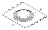
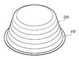
도 1은 본 발명의 바람직한 일 실시예에 따른 일회용 멸균 부항장치가 포장 된 것을 나타낸 도면이고, 도 2는 도 1의 일회용 멸균 부항장치를 나타낸 도면이다.1 is a view showing that the disposable sterile cupping device according to an embodiment of the present invention is packaged, Figure 2 is a view showing the disposable sterile cupping device of FIG.
도면을 참조하면, 본 발명은 접힘가능한 재질인 팽창부(20)와, 상기 팽창부(20)의 테두리에 구성되는 체결부(40)를 포함한다.Referring to the drawings, the present invention includes a
상기 팽창부(20)는 접힘이 가능한 재질, 즉 단단해서 이미 고정된 외형을 가지지 않고 절곡되거나 구부러져서 서로 겹치는 것이 가능한 재질로 이루어진다.The
물론, 팽창부(20)는 유연한 재질일 수 있으며, 유연한 재질은 상기 접힘과 같이 팽창부(20)의 체적을 줄일 수 있는 형상으로 용이하게 변형될 수 있고 이러한 변형을 유지할 수 있다.Of course, the
또한, 상기 체결부(40)는 탄성을 지니면서 팽창부(20)의 테두리에 구성된다.In addition, the
즉, 팽창부(20)의 테두리를 따라 구성되며, 늘어나고 다시 원상태로 줄어드는 것이 가능한 탄성력을 가진다.That is, it is configured along the edge of the inflating
이와 같이 구성되는 팽창부(20)와 체결부(40)는 일체형으로서 비닐재질인 것이 바람직하지만, 물론 팽창부(20)와 체결부(40)는 본 발명에 의해 한정되지 않으며 상기와 같은 특성을 가진 재질이라면 어떠한 소재도 활용될 수 있다.The
이에 따라, 본 발명은 차지하는 공간이 거의 없을 정도로 체적이 작음으로써, 보관이나 운반시 효율적인 수행이 가능하도록 한다.Accordingly, the present invention has a small volume so that little space is occupied, thereby enabling efficient performance during storage or transportation.
나아가, 본 발명을 사용함으로써, 저렴한 비용으로도 위생적으로 그리고 간편하게 부항요법을 행할 수 있다.Furthermore, by using the present invention, it is possible to carry out cupping therapy hygienically and simply at low cost.
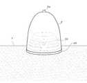
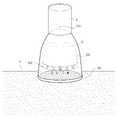
한편, 도 3은 도 1의 일회용 멸균 부항장치가 부항기(2)에 설치된 것을 나타낸 도면이다.On the other hand, Figure 3 is a view showing that the disposable sterile cupping device of Figure 1 is installed in the cupping machine (2).
도면을 참조하면, 상기 체결부(40)가 시술시 부항기(2)와 함께 활용되는 경우, 체결부(40)와 팽창부(20)가 부항기(2)의 내부에 배치되면서 체결부(40)가 부항기(2)의 하단부에 탄성 압박체결되어 체결된다.Referring to the drawings, when the
즉, 체결부(40)는 부항기(2) 하단부보다 작은 지름을 지니며, 이에 따라 부항기(2) 내부에 배치된 체결부(40)를 부항기(2) 하단부를 거쳐 외측으로 늘이면서 부항기(2) 하단부의 외면을 내측으로 압박한다.That is, the fastening
시술자가 체결부(40)를 부항기(2)의 외측까지 늘인 다음 일정정도 상측으로 올린 상태에서 체결부(40)를 놔두면 체결부(40)가 부항기(2) 하단부의 외면에 달라붙으면서 강한 힘으로 부항기(2) 하단부를 내측으로 밀면서 고정된 상태를 유지하게 된다.If the operator extends the
상기와 같은 상태에서는, 팽창부(20)에 의해 부항기(2) 내부의 피시술자의 피부(1)가 팽창부(20) 외측의 공기와 차단되게 된다.In the above state, the
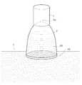
상기와 같이 구성되는 본 발명의 바람직한 일 실시예에 따른 일회용 멸균 부항장치를 부항기(2)와 함께 활용되는 것을 도 4를 참조하여 설명하기로 한다.The use of the disposable sterile cupping device according to the preferred embodiment of the present invention configured as described above with the
먼저, 부항기(2) 내에 팽창부(20)와 체결부(40)로 이루어진 일회용 멸균 부항장치를 위치시킨 다음, 팽창부(20) 테두리의 체결부(40)를 늘여서 부항기(2)의 하단부 외면을 따라 탄성압박시켜 일회용 멸균 부항장치를 부항기(2)에 대해 고정시킨다.First, the disposable sterile cupping device including the
이어서, 일회용 멸균 부항장치가 체결된 부항기(2)를 피시술자의 시술하고자 하는 치료부위 피부(1) 위에 올려놓고, 흡입기(3)를 이용하여 부항기(2) 상단에 형성된 배기홀(도 3의 2a)을 통해 부항기(2) 내의 공기압을 떨어뜨려 내부에 음압을 형성시킨다.Subsequently, the disposable sterile cupping device is placed on the
이러한 과정에서, 부항기(2) 내의 음압에 의해 팽창부(20)는 상측으로 팽창됨으로써, 상기 음압이 부항기(2) 내에서 균일한 상태를 만든다.In this process, the
여기에서, 만약 팽창부(20)가 팽창하지 않는다면, 부항기(2) 내의 음압은 팽창부(20) 외측만이 크게 형성되고 팽창부(20) 내부는 음압이 거의 형성되지 않음으로써, 팽창부(20) 내부에 위치한 피시술자의 피부(1)는 부항요법의 치료가 이루어지지 않게 된다.Here, if the
결과적으로, 본 발명에 의해 부항요법의 시술시, 팽창부(20)에 의해 부항기(2) 내부의 피시술자의 피부(1)가 팽창부(20) 외측의 공기와 차단되게 된다.As a result, when the cupping therapy is performed according to the present invention, the
이로 인하여, 피시술자의 피부(1)는 다회 사용에 의해 세균번식이 용이한 흡입기(3)와의 공기교류가 차단됨으로써, 배기홀(2a)의 통한 흡입기(3)의 세균에 의 해 감염되는 것이 방지된다.Accordingly, the
아울러, 부항기(2)에 존재하는 세균으로부터의 감염도 방지할 수 있음은 물론이며 완전 멸균포장을 통해 보다 위생적인 관리가 가능한 장점을 가진다.In addition, it is possible to prevent the infection from the bacteria present in the cupping device (2) as well as has the advantage that more hygienic management through the complete sterilization packaging.
나아가, 피부(1)에 손상을 일으키는 습식부항요법 시술시와 같이 위생적인 조치가 더욱더 필요한 경우에, 본 발명은 위생상 높은 효과를 가진다.Furthermore, in the case where hygienic measures are further required, such as during wet cupping, which causes damage to the
즉, 본 발명은 습식부항요법 시술시 출혈을 위해 유발된 상처부위가 상기 세균에 의해 감염되는 것을 효과적으로 방지할 수 있다.That is, the present invention can effectively prevent the wound area caused for bleeding during the wet cupping treatment by the bacteria.
도 5는 본 발명의 바람직한 다른 일 실시예에 따른 일회용 멸균 부항장치를 나타낸 도면이고, 도 6은 도 5의 일회용 멸균 부항장치의 팽창부가 흡입기에 의해 부항기 내에서 팽창된 것을 나타낸 도면이다.5 is a view showing a disposable sterile cupping device according to another embodiment of the present invention, Figure 6 is a view showing that the inflation portion of the disposable sterile cupping device of Figure 5 inflated in the cupping machine by the inhaler.
도면을 참조하면, 상기 일회용 멸균 부항장치는, 피시술자의 피부(1)로부터 발생되는 어혈을 흡수하도록, 피시술자의 피부(1)와 마주보는 팽창부(20)의 일측에 부착된 거즈(60)를 더 포함할 수 있다.Referring to the drawings, the disposable sterile cupping device is a
상기 거즈(60)는 피시술자의 피부(1)의 상처에서 나오는 혈액을 흡수하여 위생적으로 혈액이 처리되며, 이때 사용되는 거즈(60)는 멸균처리된 것이 바람직하다.The
여기에서, 거즈(60)는 팽창부(20)에서 상기 혈액을 흡수하기 원활한 위치에 배치되면 될 뿐, 본 발명에 의해 그 위치 및 부착방법에 대해서는 한정되지 않는 다.Here, the
결과적으로, 본 발명은 흡입기(3)와의 간접접촉으로 인하여 유발될 수 있는 세균감염을 방지하고 보관시 요구되는 체적을 줄일 수 있는 효과를 지닌다.As a result, the present invention has the effect of preventing the bacterial infection that can be caused by indirect contact with the
이상과 같이, 본 발명은 비록 한정된 실시예와 도면에 의해 설명되었으나, 본 발명은 이것에 의해 한정되지 않으며 본 발명이 속하는 기술분야에서 통상의 지식을 가진 자에 의해 본 발명의 기술사상과 아래에 기재될 특허청구범위의 균등범위 내에서 다양한 수정 및 변형이 가능함은 물론이다.As described above, although the present invention has been described by way of limited embodiments and drawings, the present invention is not limited thereto and is intended by those skilled in the art to which the present invention pertains. Of course, various modifications and variations are possible within the scope of equivalents of the claims to be described.
도 1은 본 발명의 바람직한 일 실시예에 따른 일회용 멸균 부항장치가 포장된 것을 나타낸 도면이다.1 is a view showing a disposable sterile cupping device is packaged according to an embodiment of the present invention.
도 2는 도 1의 일회용 멸균 부항장치를 나타낸 도면이다.2 is a view showing the disposable sterilization cupping device of FIG.
도 3은 도 1의 일회용 멸균 부항장치가 부항기에 설치된 것을 나타낸 도면이다.3 is a view showing that the disposable sterile cupping device of Figure 1 is installed in the cupping machine.
도 4는 도 1의 일회용 멸균 부항장치의 팽창부가 흡입기에 의해 부항기 내에서 팽창된 것을 나타낸 도면이다.Figure 4 is a view showing that the inflation portion of the disposable sterile cupping device of Figure 1 inflated in the cupping device by the inhaler.
도 5는 본 발명의 바람직한 다른 일 실시예에 따른 일회용 멸균 부항장치를 나타낸 도면이다.5 is a view showing a disposable sterile cupping device according to another embodiment of the present invention.
도 6은 도 5의 일회용 멸균 부항장치의 팽창부가 흡입기에 의해 부항기 내에서 팽창된 것을 나타낸 도면이다.6 is a view showing that the inflation portion of the disposable sterile cupping device of Figure 5 inflated in the cupping device by the inhaler.
<도면 주요 부분에 대한 부호의 설명><Explanation of symbols for the main parts of the drawings>
1 : 피시술자의 피부2 : 부항기1: skin of subject 2: cupping machine
2a : 배기홀3 : 흡입기2a: exhaust hole 3: inhaler
20 : 팽창부40 : 체결부20: expansion portion 40: fastening portion
60 : 거즈60: Gauze
Claims (4)
Translated fromKoreanPriority Applications (6)
| Application Number | Priority Date | Filing Date | Title |
|---|---|---|---|
| KR20090073678AKR100920996B1 (en) | 2009-08-11 | 2009-08-11 | Disposable Sterilization Cupping Device |
| EP20100808280EP2465552B1 (en) | 2009-08-11 | 2010-04-09 | Disposable sterilized cupping therapy apparatus |
| US13/377,874US9095647B2 (en) | 2009-08-11 | 2010-04-09 | Disposable sterilized cupping therapy apparatus |
| PCT/KR2010/002198WO2011019131A1 (en) | 2009-08-11 | 2010-04-09 | Disposable sterilized cupping therapy apparatus |
| JP2012515962AJP5271451B2 (en) | 2009-08-11 | 2010-04-09 | Disposable sterilization equipment |
| CN201080026498.9ACN102470204B (en) | 2009-08-11 | 2010-04-09 | Disposable sterilized cupping therapy apparatus |
Applications Claiming Priority (1)
| Application Number | Priority Date | Filing Date | Title |
|---|---|---|---|
| KR20090073678AKR100920996B1 (en) | 2009-08-11 | 2009-08-11 | Disposable Sterilization Cupping Device |
Publications (1)
| Publication Number | Publication Date |
|---|---|
| KR100920996B1true KR100920996B1 (en) | 2009-10-09 |
Family
ID=41572178
Family Applications (1)
| Application Number | Title | Priority Date | Filing Date |
|---|---|---|---|
| KR20090073678AActiveKR100920996B1 (en) | 2009-08-11 | 2009-08-11 | Disposable Sterilization Cupping Device |
Country Status (6)
| Country | Link |
|---|---|
| US (1) | US9095647B2 (en) |
| EP (1) | EP2465552B1 (en) |
| JP (1) | JP5271451B2 (en) |
| KR (1) | KR100920996B1 (en) |
| CN (1) | CN102470204B (en) |
| WO (1) | WO2011019131A1 (en) |
Cited By (2)
| Publication number | Priority date | Publication date | Assignee | Title |
|---|---|---|---|---|
| WO2012173414A3 (en)* | 2011-06-14 | 2013-02-07 | 한국한의학연구원 | Disposable sterilizing cupping device |
| KR20160069634A (en)* | 2014-12-09 | 2016-06-17 | 임헌경 | Cupping cup made of silicon |
Families Citing this family (10)
| Publication number | Priority date | Publication date | Assignee | Title |
|---|---|---|---|---|
| CN105363077A (en)* | 2014-08-21 | 2016-03-02 | 张超伦 | Cupping vessel with disposable film sleeves |
| JP1603611S (en)* | 2017-09-29 | 2018-05-14 | ||
| CN110787332A (en)* | 2019-11-08 | 2020-02-14 | 超科毕力格 | Alcohol cupping device applied to Shenque acupoint |
| USD893038S1 (en) | 2020-01-23 | 2020-08-11 | Lure Enterprises Limited Liability Company | Cupping device |
| USD888979S1 (en) | 2020-01-23 | 2020-06-30 | Lure Enterprises Limited Liability Company | Cupping device |
| USD888972S1 (en) | 2020-01-23 | 2020-06-30 | Lure Enterprises Limited Liability Company | Cupping device |
| USD893037S1 (en) | 2020-01-23 | 2020-08-11 | Lure Enterprises Limited Liability Company | Cupping device |
| US20220008632A1 (en)* | 2020-07-13 | 2022-01-13 | Wellness Allied Inc | Cupping auxiliary consumable, cupping kit, and cupping method |
| CN111760097B (en)* | 2020-07-30 | 2025-05-02 | 浙江中医药大学附属第三医院 | Auxiliary cupping isolation device for preventing cross infection |
| USD942027S1 (en)* | 2020-09-23 | 2022-01-25 | Jil Sharon Moramarco | Heart shaped suction cupping therapy cup |
Citations (3)
| Publication number | Priority date | Publication date | Assignee | Title |
|---|---|---|---|---|
| KR200264423Y1 (en) | 2001-11-16 | 2002-02-19 | 김근식 | A jar of cupping |
| KR20090004791U (en)* | 2007-11-15 | 2009-05-20 | 추래흥 | Disposable cupping cup with fish blood absorbing material |
| KR20090078010A (en)* | 2008-01-14 | 2009-07-17 | 이동훈 | Disposable pad protects cup cup contamination of pathogens from skin during cupping |
Family Cites Families (12)
| Publication number | Priority date | Publication date | Assignee | Title |
|---|---|---|---|---|
| JPS5713040U (en)* | 1980-06-23 | 1982-01-23 | ||
| CN2104665U (en)* | 1991-09-06 | 1992-05-20 | 陈智有 | Simple cupping cup |
| JP3061916B2 (en)* | 1991-12-13 | 2000-07-10 | 住友ベークライト株式会社 | Body fluid suction collector |
| IL120910A (en)* | 1997-05-26 | 2004-01-04 | Lrr & D Ltd | Multipurpose dynamic occlusive dressing |
| US6506149B2 (en)* | 1999-09-07 | 2003-01-14 | Origin Medsystems, Inc. | Organ manipulator having suction member supported with freedom to move relative to its support |
| US20020117169A1 (en)* | 2001-02-27 | 2002-08-29 | Kurz Daniel R. | Cover and applicator for a portion of a mammalian body |
| KR100470808B1 (en) | 2002-09-04 | 2005-03-10 | 배삼훈 | Telescopic suction tube cupping machine |
| US20050267386A1 (en)* | 2004-05-25 | 2005-12-01 | Rachel Copelan | Breast tissue expanding device |
| KR200362549Y1 (en) | 2004-06-16 | 2004-09-22 | 이선구 | Cupping cup of cupping device |
| KR100877558B1 (en)* | 2007-04-04 | 2009-01-09 | 곽병일 | Cupping sanitary cap |
| KR200441651Y1 (en) | 2007-05-07 | 2008-08-29 | 이영철 | Disposable cupping pad |
| CN102036699B (en)* | 2008-05-30 | 2013-08-21 | 凯希特许有限公司 | Decompression Linear Wound Therapy System |
- 2009
- 2009-08-11KRKR20090073678Apatent/KR100920996B1/enactiveActive
- 2010
- 2010-04-09CNCN201080026498.9Apatent/CN102470204B/enactiveActive
- 2010-04-09EPEP20100808280patent/EP2465552B1/enactiveActive
- 2010-04-09WOPCT/KR2010/002198patent/WO2011019131A1/enactiveApplication Filing
- 2010-04-09JPJP2012515962Apatent/JP5271451B2/enactiveActive
- 2010-04-09USUS13/377,874patent/US9095647B2/enactiveActive
Patent Citations (3)
| Publication number | Priority date | Publication date | Assignee | Title |
|---|---|---|---|---|
| KR200264423Y1 (en) | 2001-11-16 | 2002-02-19 | 김근식 | A jar of cupping |
| KR20090004791U (en)* | 2007-11-15 | 2009-05-20 | 추래흥 | Disposable cupping cup with fish blood absorbing material |
| KR20090078010A (en)* | 2008-01-14 | 2009-07-17 | 이동훈 | Disposable pad protects cup cup contamination of pathogens from skin during cupping |
Cited By (4)
| Publication number | Priority date | Publication date | Assignee | Title |
|---|---|---|---|---|
| WO2012173414A3 (en)* | 2011-06-14 | 2013-02-07 | 한국한의학연구원 | Disposable sterilizing cupping device |
| KR101272317B1 (en)* | 2011-06-14 | 2013-06-07 | 한국 한의학 연구원 | Disposable sterilization cupping device |
| KR20160069634A (en)* | 2014-12-09 | 2016-06-17 | 임헌경 | Cupping cup made of silicon |
| KR101709722B1 (en) | 2014-12-09 | 2017-02-23 | 임헌경 | Cupping cup made of silicon |
Also Published As
| Publication number | Publication date |
|---|---|
| CN102470204A (en) | 2012-05-23 |
| EP2465552A4 (en) | 2013-07-31 |
| WO2011019131A1 (en) | 2011-02-17 |
| JP5271451B2 (en) | 2013-08-21 |
| CN102470204B (en) | 2015-03-11 |
| US9095647B2 (en) | 2015-08-04 |
| EP2465552A1 (en) | 2012-06-20 |
| EP2465552B1 (en) | 2015-01-14 |
| JP2012529966A (en) | 2012-11-29 |
| US20120089066A1 (en) | 2012-04-12 |
Similar Documents
| Publication | Publication Date | Title |
|---|---|---|
| KR100920996B1 (en) | Disposable Sterilization Cupping Device | |
| US8020561B2 (en) | Surgical drape having a fluid collection pouch with an inflatable rim | |
| CN101553196A (en) | Eyelids opening device with drape | |
| KR101272317B1 (en) | Disposable sterilization cupping device | |
| US7096871B2 (en) | Surgical drape having a fluid collection pouch with an inflatable rim | |
| KR200441651Y1 (en) | Disposable cupping pad | |
| CN204352260U (en) | A kind of drainage device | |
| KR101481279B1 (en) | Tourniquet | |
| CN106821596A (en) | A kind of low irritability strong pressurizing imbibition application | |
| CN108778203A (en) | Surgical bandage with stable element | |
| CN110151246A (en) | A hemostatic device for medical care | |
| KR200449836Y1 (en) | Filter movable in cupping cup and cupping cup with the filter | |
| KR100930339B1 (en) | Disposable Fish Blood Absorbing Pad for Cupping Cup | |
| CN208435940U (en) | An ophthalmic medical gauze storage device | |
| CN210096028U (en) | Vacuum medical orthopedic fixation device attached to affected part | |
| US7621278B2 (en) | Eye drape for surgical procedures | |
| CN209984438U (en) | A pressure-adjustable adhesive dressing capable of preventing ascites puncture leakage and absorbing exudate | |
| KR100877558B1 (en) | Cupping sanitary cap | |
| KR200488406Y1 (en) | The shower cover for gips patient | |
| CN214048962U (en) | Household nasal cavity hemostasis device | |
| KR102740059B1 (en) | Plastic wrap with built-in absorbent pad | |
| CN202313451U (en) | Isolation device in intraoperative abdominal viscera examination for general surgery department | |
| CN204394701U (en) | In art, cotton piece puts dish | |
| CN217772607U (en) | Negative-pressure sunken nipple correction device for obstetrics and gynecology | |
| CN218979927U (en) | A kind of negative pressure drainage tube for flushing infected incision |
Legal Events
| Date | Code | Title | Description |
|---|---|---|---|
| A201 | Request for examination | ||
| PA0109 | Patent application | Patent event code:PA01091R01D Comment text:Patent Application Patent event date:20090811 | |
| PA0201 | Request for examination | ||
| A302 | Request for accelerated examination | ||
| PA0302 | Request for accelerated examination | Patent event date:20090907 Patent event code:PA03022R01D Comment text:Request for Accelerated Examination Patent event date:20090811 Patent event code:PA03021R01I Comment text:Patent Application | |
| E701 | Decision to grant or registration of patent right | ||
| PE0701 | Decision of registration | Patent event code:PE07011S01D Comment text:Decision to Grant Registration Patent event date:20090929 | |
| GRNT | Written decision to grant | ||
| PR0701 | Registration of establishment | Comment text:Registration of Establishment Patent event date:20091001 Patent event code:PR07011E01D | |
| PR1002 | Payment of registration fee | Payment date:20091005 End annual number:3 Start annual number:1 | |
| PG1601 | Publication of registration | ||
| FPAY | Annual fee payment | Payment date:20121004 Year of fee payment:4 | |
| PR1001 | Payment of annual fee | Payment date:20121004 Start annual number:4 End annual number:4 | |
| FPAY | Annual fee payment | Payment date:20131002 Year of fee payment:5 | |
| PR1001 | Payment of annual fee | Payment date:20131002 Start annual number:5 End annual number:5 | |
| FPAY | Annual fee payment | Payment date:20140725 Year of fee payment:6 | |
| PR1001 | Payment of annual fee | Payment date:20140725 Start annual number:6 End annual number:6 | |
| FPAY | Annual fee payment | Payment date:20151002 Year of fee payment:7 | |
| PR1001 | Payment of annual fee | Payment date:20151002 Start annual number:7 End annual number:7 | |
| FPAY | Annual fee payment | Payment date:20171010 Year of fee payment:9 | |
| PR1001 | Payment of annual fee | Payment date:20171010 Start annual number:9 End annual number:9 | |
| FPAY | Annual fee payment | Payment date:20181002 Year of fee payment:10 | |
| PR1001 | Payment of annual fee | Payment date:20181002 Start annual number:10 End annual number:10 | |
| FPAY | Annual fee payment | Payment date:20190926 Year of fee payment:11 | |
| PR1001 | Payment of annual fee | Payment date:20190926 Start annual number:11 End annual number:11 | |
| PR1001 | Payment of annual fee | Payment date:20200923 Start annual number:12 End annual number:12 | |
| PR1001 | Payment of annual fee | Payment date:20220920 Start annual number:14 End annual number:14 | |
| PR1001 | Payment of annual fee | Payment date:20230921 Start annual number:15 End annual number:15 | |
| PR1001 | Payment of annual fee | Payment date:20240801 Start annual number:16 End annual number:16 |