KR100920993B1 - Coin separator - Google Patents
Coin separatorDownload PDFInfo
- Publication number
- KR100920993B1 KR100920993B1KR1020020072374AKR20020072374AKR100920993B1KR 100920993 B1KR100920993 B1KR 100920993B1KR 1020020072374 AKR1020020072374 AKR 1020020072374AKR 20020072374 AKR20020072374 AKR 20020072374AKR 100920993 B1KR100920993 B1KR 100920993B1
- Authority
- KR
- South Korea
- Prior art keywords
- coin
- coins
- storage container
- storage
- guide
- Prior art date
- Legal status (The legal status is an assumption and is not a legal conclusion. Google has not performed a legal analysis and makes no representation as to the accuracy of the status listed.)
- Expired - Fee Related
Links
Images


Classifications
- G—PHYSICS
- G07—CHECKING-DEVICES
- G07D—HANDLING OF COINS OR VALUABLE PAPERS, e.g. TESTING, SORTING BY DENOMINATIONS, COUNTING, DISPENSING, CHANGING OR DEPOSITING
- G07D3/00—Sorting a mixed bulk of coins into denominations
- G07D3/02—Sorting coins by means of graded apertures
- G—PHYSICS
- G07—CHECKING-DEVICES
- G07D—HANDLING OF COINS OR VALUABLE PAPERS, e.g. TESTING, SORTING BY DENOMINATIONS, COUNTING, DISPENSING, CHANGING OR DEPOSITING
- G07D9/00—Counting coins; Handling of coins not provided for in the other groups of this subclass
Landscapes
- Physics & Mathematics (AREA)
- General Physics & Mathematics (AREA)
- Control Of Vending Devices And Auxiliary Devices For Vending Devices (AREA)
Abstract
Translated fromKoreanDescription
Translated fromKorean도 1은 종래의 일반적인 동전분리기의 외관을 설명하는 도면.1 is a view for explaining the appearance of a conventional general coin separator.
도 2는 종래의 일반적인 동전분리기의 단면을 설명하는 도면.2 is a view illustrating a cross section of a conventional general coin separator.
도 3은 종래의 동전분리기에 있어서 동전수납관의 취출장치를 설명하는 도면.Figure 3 is a view for explaining a takeout device of the coin storage pipe in the conventional coin separator.
도 4는 종래의 동전분리기에 있어서 동전수납관의 취출장치를 설명하는 도면.Figure 4 is a view for explaining a coin take-out device of the conventional coin separator.
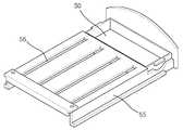
도 5는 낙전서랍이 당겨져 전원이 꺼지고 경사체에 의해 수납용기가 상승된 상태를 설명하는 사시도.5 is a perspective view illustrating a state in which the drawer drawer is pulled out and the power is turned off and the storage container is lifted by the inclined body;
도 6은 종래의 동전분리기에 있어서 동전이 수납되는 원리를 설명하는 도면.6 is a view for explaining the principle of storing coins in the conventional coin separator.
도 7은 본 발명에 따른 동전분리기에 있어서 동전이 수납되는 원리를 설명하는 도면.7 is a view for explaining the principle of storing coins in the coin separator according to the present invention.
도 8은 본 발명에 따른 동전분리기에 있어서 동전수납관이 장착된 수납용기의 사시도.8 is a perspective view of a storage container equipped with a coin storage tube in the coin separator according to the present invention.
도 9는 본 발명에 따른 동전분리기에 있어서 동전수납관이 장착된 수납용기의 다른 실시예.Figure 9 is another embodiment of the storage container equipped with a coin storage tube in the coin separator according to the present invention.
도 10은 본 발명에 따른 동전분리기에 있어서 수납용기가 결합되는 슬라이딩 부재를 설명하는 도면.10 is a view for explaining a sliding member coupled to the storage container in the coin separator according to the present invention.
도 11은 수납용기와 슬라이딩 부재가 결합된 것을 설명하는 도면.11 is a view explaining that the storage container and the sliding member are coupled.
도 12는 본 발명에 따른 동전분리기의 외관을 설명하는 도면.12 is a view for explaining the appearance of a coin separator according to the present invention.
도 13은 본 발명에 따른 동전분리기에 있어서 동전수납 장치의 작동을 설명하는 동전분리기의 단면도.Figure 13 is a cross-sectional view of the coin separator illustrating the operation of the coin storage device in the coin separator according to the present invention.
도 14는 본 발명에 따른 동전분리기에 있어서, 수납용기가 이동된 상태를 설명하는 도면.14 is a view illustrating a state in which a storage container is moved in the coin separator according to the present invention.
도 15는 본 발명에 따른 동전분리기에 있어서 동전의 분리가 끝난 후 슬라이딩 부재를 당긴 상태를 설명하는 도면.15 is a view illustrating a state in which a sliding member is pulled after the separation of coins in the coin separator according to the present invention.
〈도면의 주요부분에 대한 부호의 설명〉<Explanation of symbols for main parts of drawing>
10 ; 동전투입구 11 ; 공급조절용기10;
12 ; 공급구 13 ; 운반용기12;
14 ; 운반홀 15 ; 커버14; Conveying
16 ; 분리홀 17 ; 모터16;
18 ; 회전축 19 ; 돌출부18; Axis of
30 ; 가이드 40 ; 동전수납관30;
40a ; 동전수납관 40b ; 동전수납관40a;
41 ; 수납용기 41a ; 슬라이딩 돌기41;
41b ; 인출손잡이 42 ; 돌기41b;
43 ; 홈 44 ; 롤러43; Groove 44; roller
50 ; 낙전서랍 51 ; 경사체50; Chest of
52 ; 차단막 54 ; 마이크로 스위치52; Barrier
55 ; 슬라이딩 부재 56 ; 슬라이딩 홈55; Sliding
60 ; 전원장치60; Power supply
본 발명은 동전을 분리하는 장치에 관한 것으로써 특히, 동전투입구로 여러 종류의 동전을 투입하면 크기에 따라 동전이 분류되는 동전분리기에 관한 것이다.The present invention relates to a device for separating coins, and more particularly, to a coin separator in which coins are classified according to size when a plurality of coins are put into a coin inlet.
동전 분리기는 동전을 크기에 따라 분리함으로써 많은 양의 동전을 종류에 따라 분리되도록 하는 기계를 말하는데, 은행과 같은 금융기관이나 상거래 현장에서 동전을 신속하고 정확하게 분리하고자 하는 경우에 많이 사용된다.Coin separator is a machine that separates coins according to size so that a large amount of coins can be separated by type. It is often used when you want to separate coins quickly and accurately in financial institutions such as banks or commerce sites.
도 1은 종래의 일반적인 동전분리기의 외관을 설명하는 도면이다.1 is a view for explaining the appearance of a conventional coin separator.
도 1을 참조하여 일반적인 동전분리기의 외관을 살펴보면, 다량의 동전이 투입되는 동전투입구(10)와, 상기 동전투입구(10)에 투입된 동전이 크기에 따라 분리되어 수납되도록 하는 가이드(30)와, 상기 가이드(30)를 통해 이동된 동전이 일정량 만큼 수납되는 동전수납관(40)과, 동전수납관(40)에 수납되지 않은 동전을 모아주는 낙전서랍(50)과, 동전분리기에 전원을 공급 또는 차단해주는 전원장치(60)가 포함된다.Looking at the appearance of a general coin separator with reference to Figure 1, a
상기와 같이 구성된 동전분리기의 작동방법을 간단히 설명하면, 사용자가 전 원장치(60)를 켜고 동전투입구(10)에 동전을 투입하면 동전투입구(10) 하측의 분리장치에 의해 크기에 따라 동전이 분리되어 가이드(30)를 통해 배출된다.When the operation method of the coin separator configured as described above is briefly described, when the user turns on the
가이드(30)를 통해 배출된 동전은 동전수납관(40)에 쌓이게 되는데, 도 1에서 보는 바와같이 동전수납관(40)이 2단으로 구성된 경우에는 가이드(30)에 인접한 동전수납관(40)에 먼저 동전이 수납된다.Coins discharged through the
가이드(30)에 인접한 동전수납관(40)이 포화된 경우에는 두번째 동전수납관(40)에 동전이 수납된다.When the
사용자는 동전수납관(40)에 동전이 가득찬 경우에 전원장치(60)를 끄고 동전수납관(40)을 꺼내 분리된 동전을 필요한 용도에 사용하게 된다.The user turns off the
도 2는 종래의 일반적인 동전분리기의 단면을 설명하는 도면이다.2 is a view for explaining the cross section of a conventional coin separator.
도 2를 참조하면, 동전분리기는 동전이 투입되는 동전투입구(10)와, 상기 동전투입구(10)를 통해 투입된 많은 양의 동전이 소량씩 분리장치내로 투입되도록 하는 공급조절용기(11)와, 상기 공급조절용기(11)의 측면에 형성되며 소량의 동전이 투입되도록 하는 공급구(12)와, 상기 공급조절용기(11)가 회전되면서 동전이 외부로 이탈되지 않도록 하는 커버(15)와, 상기 공급구(12)를 통해 투입된 동전이 운반홀(14)과 분리홀(16)에 의해 분리되도록 운반해주는 운반용기(13)와, 상기 공급조절용기(11)와 운반용기(13)가 회전되도록 하는 회전축(18)과, 모터(17)가 포함된다.Referring to Figure 2, the coin separator is a coin inlet (10), the coin is inserted into the supply control container (11) so that a large amount of coins introduced through the
또한, 상기 분리홀(16)에서 분리된 동전이 분리되어 수납되도록 하는 가이드(30)와, 상기 가이드(30)를 통해 크기에 따라 분리되어 나오는 동전이 수납 되는 동전수납관(40)과, 상기 동전수납관(40)이 수납되는 수납용기(41)와, 상기 동전수납관(40)에 수납되지 않고 이탈된 동전이 모아지는 낙전서랍(50)이 포함된다.In addition, the
상기한 구성을 가지는 종래의 동전분리기의 작동에 대해 설명하면, 동전투입구(10)를 통해 다량의 동전이 투입되면 공급조절용기(11)에 동전이 쌓이게 되고 상기 공급조절용기(11)가 회전함에 따라 공급조절용기(11)의 측면에 형성된 공급구(12)를 통해 소량의 동전이 운반용기(13)로 투입된다.Referring to the operation of the conventional coin separator having the above configuration, when a large amount of coins are put through the
운반용기(13)가 회전하면서 운반용기(13)에 형성된 운반홀(14)에 동전이 삽입되어 운반용기(13)의 회전에 따라 분리홀(16)로 이동된다.As the
상기 분리홀(16)은 서로 다른 크기의 홀이 형성되어 있는데, 운반홀(14)의 회전방향에 따라 작은 크기의 홀에서 큰 크기의 홀의 순서로 홀이 형성된다.The
따라서, 동전의 크기에 따라 작은 크기의 동전이 먼저 분리홀(16)을 통해 빠져나가고 최종적으로 가장 큰 크기의 동전이 분리홀(16)을 통해 빠져나가게 된다.Therefore, according to the size of the coin, a small coin is first exited through the
이러한 공급조절용기(11)와 운반용기(13)의 회전은 회전축(18)과 상기 운반용기(13) 하측에 형성된 모터(17)에 의해 이루어진다.The rotation of the
상기 분리홀(16)을 통해 분리된 동전은 가이드(30)에 의해 분리된 상태로 동전수납관(40)에 수납된다.Coins separated through the
상기 동전수납관(40)은 크기에 따라 하나씩의 동전수납관(40)이 설치될 수 있으며 도면에서 보는 바와같이 동일한 크기의 동전에 2개의 동전수납관(40)이 설치될 수 있다.The
2개의 동전수납관(40)에 동전이 모두 찬 경우에 동전은 낙전서랍(50)으로 떨 어져 모아진다.If both coins are filled in two
동전의 분리가 끝나면 사용자는 동전수납관(40)을 꺼내 원하는 종류의 동전을 분리할 수 있다.After the separation of the coins, the user can take out the
도 3과 도 4는 종래의 동전분리기에 있어서 동전수납관의 취출장치를 설명하는 도면이다.3 and 4 is a view for explaining a coin take-out device in the conventional coin separator.
도 3과 도 4를 참조하면, 종래의 동전분리기는 동력이 발생되는 모터(17)와, 상기 모터(17)에서 발생된 회전력을 전달하는 회전축(18)과, 중앙부가 오목하고 회전함에 따라 일정량의 동전이 공급될 수 있도록 측면에 공급구(12)가 형성된 공급조절용기(11)와, 상기 공급조절용기(11)의 상측에 결합되고 중앙에 동전투입구(10)가 형성되며 동전이 이탈되지 않도록 하는 커버(15)와, 상기 공급조절용기(11)의 하측에 형성되며 동전이 낱개로 적재되도록 운반홀(14)이 형성된 운반용기(13)와, 상기 운반홀(14)에 의해 운반된 동전이 크기가 따라 분리될 수 있도록 다수개의 크기가 다른 분리홀(16)과, 상기 분리홀(16)에서 분리된 동전이 소정의 위치에 수납되도록 하는 가이드(30)와, 상기 가이드(30)에서 낙하된 동전이 수납되는 동전수납관(40)과, 상기 동전수납관(40)이 장착되는 수납용기(41)와, 상기 동전수납관(40)에 수납되지 않고 이탈된 동전이 모아지는 낙전서랍(50)과, 상기 낙전서랍(50)과 일체로 되어 있으며 상기 수납용기(41)가 이동될 수 있는 경사면을 제공하는 경사체(51)와, 상기 경사체(51)의 경사면을 따라 수납용기(41)가 용이하게 이동되도록 수납용기(41)의 하측에 형성된 롤러(44)와, 상기 경사체(51)의 후면에 부착되어 경사체(51)의 접착/탈착 여부에 따라 전원이 온/오프 되도록 하는 마이크로 스위치(54)로 구성된다.Referring to Figures 3 and 4, the conventional coin separator has a
또한, 상기 수납용기(41)가 경사체(51)의 전후 이동에 의해 상하로만 이동되도록 수납용기(41)에 형성된 돌기(42)와 동전 분리기 내벽에 형성된 홈(43)이 더 포함된다.In addition, the
상기와 같이 구성된 종래의 동전분리기에 있어서 동전수납관 취출장치에 대해 설명하면, 동전투입구(10)를 통해 다량의 동전이 투입되면 공급조절용기(11)에 동전이 쌓이게 되고 상기 공급조절용기(11)가 회전함에 따라 공급조절용기(11)의 측면에 형성된 공급구(12)를 통해 소량의 동전이 운반용기(13)로 투입된다.Referring to the coin storage tube take-out device in the conventional coin separator configured as described above, when a large amount of coins are put through the
운반용기(13)가 회전하면서 운반용기(13)에 형성된 운반홀(14)에 동전이 삽입되어 운반용기(13)의 회전에 따라 분리홀(16)을 통해 분리되고, 가이드(30)에 의해 분리된 채 동전수납관(40)에 수납된다.As the
동전수납관(40)에 수납되지 못한 동전은 낙전서랍(50)에 모아지게 되는데 이때 차단막(52)은 동전이 동전분리기의 외부로 이탈되지 않도록 한다.Coins that are not stored in the
동전의 분리가 끝난 경우에 사용자는 전원을 오프시키거나 낙전서랍(50)을 당기면 낙전서랍(50)의 후측에 연결된 경사체(51)가 같이 이동되고 이때 경사체(51)와 마이크로 스위치(54)가 분리되어 전원이 꺼지게 된다.When the coin is separated, the user turns off the power or pulls the
동시에 경사체(51)가 낙전서랍(50)방향으로 이동되므로 상기 수납용기(41)는 롤러(44)에 의해 적은 마찰력을 받으며 경사체(51)의 경사면을 타고 올라가게 된다.At the same time, since the
즉, 수납용기(41)의 양측은 돌기(42)에 의해 동전 분리기 내벽에 형성된 홈(43)과 결합되어 있으므로 경사체(51)의 이동에 의해 전후이동 없이 수납용기(41)는 상하로만 움직이게 된다.That is, both sides of the
즉, 경사체(51)가 당겨지게 되면 전원이 오프되는 동시에 수납용기(41)는 상측으로 이동하게 된다.That is, when the
도 4에는 수납용기(41)가 경사체(51)의 경사면을 따라 상승되어 있고 마이크로 스위치(54)와 경사체(51)가 탈착되어 전원이 꺼져있는 상태가 잘 나타나 있다.4 illustrates a state in which the
도 5는 낙전서랍이 당겨져 전원이 꺼지고 경사체에 의해 수납용기가 상승된 상태를 설명하는 사시도이다.5 is a perspective view illustrating a state in which the drawer drawer is pulled out and the power is turned off, and the storage container is lifted by the inclined body.
도 5를 참조하면, 도 3과 도 4에서 설명한 바와같이 낙전서랍(50)을 당기게 되면 전원이 꺼지고 수납용기(41)가 상승하여 사용자는 수납용기(41)에 장착된 동전수납관(40)을 꺼내게 된다.Referring to FIG. 5, as described above with reference to FIGS. 3 and 4, when the
이때 도면에서 보는 바와같이 동전수납관(40)이 조밀하게 형성되어 있고 2열로 되어 있는 경우에 모든 동전수납관(40)이 동시에 상승하므로써 사용자는 동전수납관(40)을 수납용기(41)에서 꺼내는데 불편함이 있다.At this time, as shown in the drawing, when the
특히, 손가락이 굵거나 장갑등을 착용하고 있는 경우에는 더욱 불편함이 있다.In particular, when the fingers are thick or wearing gloves, there is more discomfort.
도 6은 종래의 동전분리기에 있어서 동전이 수납되는 원리를 설명하는 도면이다.6 is a view for explaining the principle of storing coins in the conventional coin separator.
도 6을 참조하면, 종래의 동전분리기는 중력에 의한 자유낙하의 원리를 이용하여 가이드(30)를 통해 동전이 분리되면 먼저 가이드(30)에 인접한 동전수납관(40a)에 동전이 쌓이고, 상기 동전수납관(40a)에 동전이 가득 수납된 경우에 그 다음 동전수납관(40b)에 동전이 수납되게 된다.Referring to FIG. 6, when a coin is separated through the
즉, 물이 넘쳐흐르는 원리를 이용하여 하나 이상의 동전수납관(40)에 동일한 크기의 동전이 수납되도록 한다.That is, using the principle that the water overflows to allow the coin of the same size in one or more
상기와 같이 종래의 동전수납관(40)은 분리된 동전이 가이드(30)를 통해 자유낙하하여 동전수납관(40)에 수납되는데, 가이드(30)에 인접한 동전수납관(40a)에 동전이 다 채워지고 두번째 동전수납관(40)에 동전이 수납되는 과정에서 동전이 인접한 다른 크기의 동전수납관(40)에 수납되는 문제점이 있다.As described above, in the conventional
또한, 하나의 동전수납관(40)이 다 채워진 경우에 전체 동전분리기의 작동을 정지하여야 동전이 다 채워진 동전수납관(40)을 꺼낼 수 있는 불편함이 있다.In addition, when one
본 발명은 상기한 문제점을 해결하기 위한 것으로서 본 발명에 따른 동전분리기는 가이드를 통해 배출되는 동전이 다른 크기의 동전수납관에 수납되는 문제점을 해결하고자 한다.The present invention is to solve the above problems, the coin separator according to the present invention is to solve the problem that the coins discharged through the guide is stored in a coin storage tube of different sizes.
또한, 모든 동전의 분리가 끝나지 않은 경우에도 동전이 다 채워진 동전수납관만 꺼낼 수 있도록 하는데 그 목적이 있다.In addition, even if the separation of all the coins is not finished, the purpose is to only take out the coin container filled with coins.
이하, 첨부된 도면을 참조하여 본 발명에 따른 동전분리기에 대해 보다 상세히 설명하도록 한다.Hereinafter, with reference to the accompanying drawings to be described in more detail with respect to the coin separator according to the present invention.
도 7은 본 발명에 따른 동전분리기에 있어서 동전이 수납되는 원리를 설명하 는 도면이다.7 is a view for explaining the principle of storing coins in the coin separator according to the present invention.
도 7을 참조하면, 본 발명에 따른 동전분리기의 동전수납 방법은 크기에 따라 분리된 동전이 소정의 위치로 가이드(30)를 따라 이동하는 단계와, 상기 가이드(30)에 인접한 첫번째 동전수납관(40a)에 동전이 채워지는 단계와, 상기 첫번째 동전수납관(40a)에 동전이 소정량 채워진 경우에 첫번째 동전수납관(40a)이 소정의 방향(A)으로 이동되면서 다른 동전수납관(40b)이 첫번째 동전수납관(40a)의 자리에 위치하는 단계가 포함된다.Referring to FIG. 7, in the coin storage method of the coin separator according to the present invention, the coin separated according to the size is moved along the
보다 상세히 설명하면, 상기 동전수납관(40)은 동일한 동전 크기에 2이상 구비될수 있으며, 첫번째 동전수납관(40a)이 이동하는 방향은 임의로 정해질 수 있다.In more detail, the
또한, 상기 동전수납관(40)은 상기 가이드(30)의 기울어진 각도와 30°이하의 각도차이로 기울어져 형성되는 것이 바람직하고, 보다 바람직하게는 상기 가이드(30)의 기울어진 각도와 동일한 각도로 기울어져 가이드(30)를 따라 이동된 동전이 용이하게 수납되도록 하는 것이 바람직하다.In addition, the
또한, 동전수납관(40)은 수납용기에 설치되어 수납용기의 이동에 따라 이동되도록 하는 것이 바람직한데, 상기 수납용기의 이동은 사용자가 임의로 손으로 이동시킬 수 있으며, 동전수납관(40)에 수납된 동전의 무게를 감지하여 자동으로 이동되도록 하는 것도 가능하다.In addition, the
이러한 수납용기의 이동은 기계적, 전자적인 방법을 활용함으로써 구현될 수 있다.The movement of the container may be implemented by using a mechanical and electronic method.
상기한 바와같이 본 발명은 가이드(30)에 인접한 첫번째 동전수납관(40a)에 동전이 수납되고, 첫번째 동전수납관(40a)에 소정량의 동전이 수납된 경우에는 동전수납관(40)이 장착된 수납용기가 소정 방향으로 이동됨에 따라 첫번째 동전수납관(40a)에 인접한 다른 동전수납관(40b)이 첫번째 동전수납관(40a)의 위치를 위치함으로써 동전이 수납되는 방법이 사용된다.As described above, in the present invention, when the coin is accommodated in the first
상기의 방법은 종래의 자유낙하를 이용하여 가이드(30)에 인접한 동전수납관(40a)에 동전이 수납되고, 동전이 가득 채워진 경우에 인접한 동전수납관(40a)에 동전이 넘쳐 흘러 들어가도록 하는 방법에서 발생되는 문제점, 즉 동전이 다른 크기의 동전이 수납되는 인접한 동전수납관에 수납되거나 수납되지 않고 바닥으로 떨어지는 문제점이 해결된다.In the above method, the coin is stored in the
도 8은 본 발명에 따른 동전분리기에 있어서 동전수납관이 장착된 수납용기의 사시도이다.8 is a perspective view of a storage container equipped with a coin storage tube in the coin separator according to the present invention.
도 8을 참조하면, 수납용기(41)에는 하나 이상의 동전수납관(40)이 장착되는데, 상기 동전수납관(40)은 분리된 동전이 이동되는 가이드의 각도와 30°이하의 각도 차이로 기울어져 형성되는 것이 바람직하고, 수납용기(41)의 이동에 따라 가이드에 걸리는 문제가 발생되지 않도록 각각의 동전수납관(40)의 높이는 일정하게 형성되는 것이 바람직하다.Referring to Figure 8, the
상기 수납용기(41)의 일측에는 수납용기(41)가 소정 거리 용이하게 이동되도록 슬라이딩 돌기(41a)가 형성되고, 일측에는 수납용기(41)를 용이하게 인출 또는 인입 가능하도록 인출손잡이(41b)가 형성된다.A sliding
상기 수납용기(41)는 동전의 크기에 따라 각각 형성되며, 동일한 크기의 동전수납관(40)은 동일한 수납용기(41)에 장착된다.The
도 9는 본 발명에 따른 동전분리기에 있어서 동전수납관이 장착된 수납용기의 다른 실시예이다.9 is another embodiment of the storage container equipped with a coin storage tube in the coin separator according to the present invention.
도 9를 참조하면, 도 8과 다른 구성은 동일하나 동전수납관(40)이 장착되는 수납용기(41)가 일체로 형성되어 다른 크기의 동전수납관(40)이 하나의 수납용기(41)에 장착된다.Referring to FIG. 9, the other configuration is the same as that of FIG. 8, but the
수납용기(41)가 일체로 형성됨에 따라 생산비용이 절감되고 제조공정이 간단해지는 장점이 있다.As the
도 10은 본 발명에 따른 동전분리기에 있어서 수납용기가 결합되는 슬라이딩 부재를 설명하는 도면이다.10 is a view for explaining a sliding member coupled to the storage container in the coin separator according to the present invention.
도 10을 참조하면, 슬라이딩 부재(55)의 상측에 상기 수납용기(41)가 설치되는데, 슬라이딩 부재(55)에는 수납용기(41)가 전후로 이동가능하도록 슬라이딩 홈(56)이 형성된다.Referring to FIG. 10, the
상기 슬라이딩 홈(56)은 상기 수납용기(41)의 갯수와 동일하게 형성된다.The sliding
다만, 도 9에서 설명한 일체형 수납용기(41)의 경우에는 양측 끝단에 형성된 동전수납관(40)의 하측에만 두개가 형성될 수 있으며, 두개 이상이 형성되는 것도 가능하다.However, in the case of the
또한, 슬라이딩 부재(55)의 일측에는 동전수납관에 수납되지 않거나, 동전이 넘치는 경우에 떨어진 동전이 모아지는 낙전서랍(50)이 형성된다.In addition, one side of the sliding
도 11은 수납용기와 슬라이딩 부재가 결합된 것을 설명하는 도면이다.11 is a view for explaining that the storage container and the sliding member is coupled.
도 11에서 보는 바와같이 슬라이딩 부재(55)에 형성된 슬라이딩 홈에 슬라이딩 돌기(41a)가 결합되어 슬라이딩 홈을 따라 좌우로 이동 가능하도록 형성된다.As shown in FIG. 11, the sliding
또한, 상기 수납용기(41)에 형성된 동전수납관(40)은 소정 각도로 기울어지고 동일한 높이로 형성되는 것이 바람직하다.In addition, the
도 12는 본 발명에 따른 동전분리기의 외관을 설명하는 도면이다.12 is a view for explaining the appearance of the coin separator according to the present invention.
도 12에서 보는 바와같이 동전투입구(10)에 동전이 투입되면, 크기에 따라 분리되어 가이드(30)를 통해 배출된다.As shown in FIG. 12, when a coin is inserted into the
소정의 동전수납관(40)에 동전이 다 채워진 경우에 인출손잡이(41b)를 당기면 가이드(30)의 하측에 위치하던 동전수납관(40)이 동전의 수납을 대신하게 되고 사용자는 동전이 다 채워진 동전수납관(40)을 수납용기(41)에서 꺼낼 수 있다.When the coin is filled in the predetermined
따라서, 본 발명에서는 동전의 분리가 계속되는 과정에서도 동전이 가득 수납된 동전수납관(40)을 꺼낼 수 있다는 점에서 도 6에서 설명한 종래의 동전 수납방법의 문제점이 개선될 수 있다.Therefore, in the present invention, the problem of the conventional coin storage method described in FIG. 6 can be improved in that the
다만, 도 9에서 설명한 일체형 수납용기(41)의 경우에는 인출손잡이(41b)를 당기면 가이드(30)에 인접한 동전수납관(40) 모두가 인출된다.However, in the case of the
따라서, 동전이 가득 채워지지 않은 동전수납관(40)도 인출되나 동전의 분리가 계속되는 중에도 동전수납관(40)을 꺼낼 수 있다.Therefore, the
도 13은 본 발명에 따른 동전분리기에 있어서 동전수납 장치의 작동을 설명하는 동전분리기의 단면도이다.13 is a cross-sectional view of the coin separator illustrating the operation of the coin storage device in the coin separator according to the present invention.
먼저, 동전분리기의 구성을 설명하면, 동전분리기는 동전이 투입되는 동전투입구(10)와, 상기 동전투입구(10)를 통해 투입된 많은 양의 동전이 소량씩 분리장치내로 투입되도록 하는 공급조절용기(11)와, 상기 공급조절용기(11)의 측면에 형성되며 소량의 동전이 투입되도록 하는 공급구(12)와, 상기 공급조절용기(11)가 회전되면서 동전이 외부로 이탈되지 않도록 하는 커버(15)와, 상기 공급구(12)를 통해 투입된 동전이 운반홀(14)과 분리홀(16)에 의해 분리되도록 운반해주는 운반용기(13)와, 상기 공급조절용기(11)와 운반용기(13)가 회전되도록 하는 회전축(18)과, 모터(17)가 포함된다.First, if the description of the configuration of the coin separator, the coin separator is a coin inlet (10) into which the coin is inserted, a large amount of coins introduced through the coin inlet (10) supply control container to be introduced into the separator by a small amount ( 11), a
또한, 상기 분리홀(16)에서 분리된 동전이 분리되어 수납되도록 하는 가이드(30)와, 상기 가이드(30)를 통해 크기에 따라 분리되어 나오는 동전이 수납되는 동전수납관(40a)(40b)과, 상기 동전수납관(40a)(40b)이 수납되는 수납용기(41)와, 상기 수납용기(41)의 하측에 형성되며 수납용기(41)가 전후로 회동가능하게 결합되는 슬라이딩 부재(55)와, 상기 슬라이딩 부재(55)의 하측에는 슬라이딩 부재(55)와 수납용기(41)가 소정 거리 이상 인출되지 않도록 하는 돌출부(19)와, 상기 동전수납관(40)에 수납되지 않고 이탈된 동전이 모아지는 낙전서랍(50)이 포함된다.In addition, the
상기 동전수납관(40a)(40b)은 상기 가이드(30)의 기울어진 각도와 30°이하의 각도 차이로 기울어져 형성되는 것이 바람직하다.The coin holding tube (40a) (40b) is preferably formed to be inclined at an angle difference between the inclination angle of the
30°이상의 각도로 기울어진 경우에 동전이 제대로 수납되지 않고 외부로 이탈되는 문제가 발생될 수 있다.When tilted at an angle of 30 ° or more, a problem may occur that the coin is not properly stored and is separated out.
상기 동전수납관(40a)(40b)은 동일한 크기의 동전이 수납되는 것으로 동일한 크기로 형성되고, 가이드(30)에서 동전이 떨어지는 방향으로 형성된다.The
도면에는 두개의 동전수납관(40a)(40b)이 도시되어 있으나 상기 동전수납관(40a)(40b)은 하나, 둘 또는 그 이상의 갯수로 형성 될 수 있다.Two
또한, 상기 수납용기(41)의 일측에는 수납용기(41)의 인출이 용이하도록 인출손잡이(41b)가 형성되는 것이 바람직하다.In addition, it is preferable that the
또한, 상기 수납용기(41)의 인출 또는 인입이 용이하도록 하고 소정 거리 이상 인출 또는 인입되지 않도록 상기 슬라이딩 부재(55)에는 인출방향으로 슬라이딩 홈(56)이 형성되고, 상기 수납용기(41)의 하측에는 상기 슬라이딩 홈에 결합되는 슬라이딩 돌기(41a)가 형성된다.In addition, the sliding
또한, 상기 슬라이딩 부재(55)의 하측에는 슬라이딩 부재(55)와 수납용기(41)가 소정 거리 이상 인출되지 않도록 돌출부(19)가 형성되는 것이 바람직하다.In addition, the lower side of the sliding
상기한 동전분리기의 작동에 대해 설명하면, 동전투입구(10)를 통해 다량의 동전이 투입되면 공급조절용기(11)에 동전이 쌓이게 되고 상기 공급조절용기(11)가 회전함에 따라 공급조절용기(11)의 측면에 형성된 공급구(12)를 통해 소량의 동전이 운반용기(13)로 투입된다.Referring to the operation of the coin separator, when a large amount of coins are put through the
운반용기(13)가 회전하면서 운반용기(13)에 형성된 운반홀(14)에 동전이 삽입되어 운반용기(13)의 회전에 따라 분리홀(16)로 이동된다.As the
상기 분리홀(16)은 서로 다른 크기의 홀이 형성되어 있는데, 운반홀(14)의 회 전방향에 따라 작은 크기의 홀에서 큰 크기의 홀의 순서로 홀이 형성된다.The separation holes 16 are formed with holes of different sizes, and holes are formed in the order of the large sized holes from the small sized holes according to the rotation direction of the carrying
따라서, 동전의 크기에 따라 작은 크기의 동전이 먼저 분리홀(16)을 통해 빠져나가고 최종적으로 가장 큰 크기의 동전이 분리홀(16)을 통해 빠져나가게 된다.Therefore, according to the size of the coin, a small coin is first exited through the
이러한 공급조절용기(11)와 운반용기(13)의 회전은 회전축(18)과 상기 운반용기(13) 하측에 형성된 모터(17)에 의해 이루어진다.The rotation of the
상기 분리홀(16)을 통해 분리된 동전은 가이드(30)에 의해 분리된 상태로 동전수납관(40)에 수납된다.Coins separated through the
상기 동전수납관(40)은 크기에 따라 하나씩의 동전수납관(40)이 설치될 수 있으며 도면에서 보는 바와같이 동일한 크기의 동전에 2개의 동전수납관(40)이 설치될 수 있다.The
동전의 분리가 끝나면 사용자는 동전수납관(40)을 꺼내 원하는 종류의 동전을 분리할 수 있다.After the separation of the coins, the user can take out the
도 14는 본 발명에 따른 동전분리기에 있어서, 수납용기가 이동된 상태를 설명하는 도면이다.14 is a view illustrating a state in which the storage container is moved in the coin separator according to the present invention.
동전분리가 이루어지면 가이드(30)에 인접한 동전수납관(40a)에 동전이 채워지게 되고, 상기 동전수납관(40a)에 동전이 다 채워진 경우에 인출손잡이(41b)를 당기게 되면 수납용기(41)가 이동되고, 동전이 채워지지 않은 동전수납관(40b)이 가이드(30)에 인접하게 된다.When the coin is separated, the coin is filled in the
같은 크기의 동전이 수납되는 동전수납관(40a)(40b)은 하나의 수납용기(41)에 장착되고, 각각 다른 크기의 동전수납관(40a)(40b)이 장착된 수납용기(41)가 분 리하고자 하는 동전의 종류대로 형성되는데, 도 14는 하나의 크기의 동전수납관(40a)(40b)이 장착된 수납용기(41)를 인출한 상태를 도시한 도면이다.The
하나의 동전수납관(40a)에 동전이 다 채워진 경우에는 그 동전수납관(40a)이 장착된 수납용기(41)만 인출하고 동전수납관(40a)을 수납용기(41)에서 분리할 수 있다.When one
이 때, 동전이 채워지지 않은 다른 동전수납관(41b)이 가이드(30)에 인접하여 위치하게 되고 계속하여 동전의 수납이 이루어지게 된다.At this time, another
물론, 다른 크기의 동전이 수납되는 동전수납관(40)과 수납용기(41)는 도 13의 상태로 계속하여 동전이 수납된다.Of course, the
다만, 도 9에서 설명한 일체형 수납용기(41)의 경우에는 인출손잡이(41b)를 당기면 가이드(30)에 인접한 동전수납관(40) 모두가 인출되고, 가이드(30) 하측에 위치한 동전수납관(40)이 가이드(30)에 인접하게 위치하여 동전의 분리에 따른 동전의 수납이 계속하여 이루어지게 된다.However, in the
동전이 다 채워진 동전수납관(40a)이 장착된 수납용기(41)를 인출하는 경우에 동전이 채워지지 않은 동전수납관(40b)이 가이드(30)에 인접한 위치에서 동전을 수납할 수 있도록 슬라이딩 부재(55)에 형성된 슬라이딩 홈(56)의 길이를 조정함으로써 도면에 도시된 바와같이 수납용기(41)가 소정거리 이상 인출되지 않게된다.In the case of taking out the
도 15는 본 발명에 따른 동전분리기에 있어서 동전의 분리가 끝난 후 슬라이딩 부재를 당긴 상태를 설명하는 도면이다.15 is a view illustrating a state in which the sliding member is pulled after the separation of coins in the coin separator according to the present invention.
도 15를 참조하면, 동전의 분리가 완전히 끝난경우 낙전서랍(50)이 형성된 슬라이딩 부재(55)를 당김으로써 동전의 크기에 따른 동전수납관(40a)(40b)이 장착된 모든 수납용기(41)가 전면으로 인출되게 된다.Referring to FIG. 15, when the separation of coins is completed, all
즉, 상기 수납용기(41)는 각각 별도로 인출할 수 있으며, 슬라이딩 부재(55)를 당김으로 해서 모든 수납용기(41)를 인출할 수도 있다.That is, the
다만, 도 9에서 설명한 일체형 수납용기(41)의 경우에는 모든 수납용기(41)의 인출만이 가능하다.However, in the case of the
슬라이딩 부재(55)를 당기는 경우에 상기 수납용기(41)와 슬라이딩 부재(55)가 상기 슬라이딩 부재(55)의 하측에 형성된 돌출부(19)에 걸려 소정 거리 이상 인출되지 않게 된다.When the sliding
따라서, 사용자는 동전이 다 채워진 동전수납관(40a) 뿐만아나라 동전이 다 채워지지 않은 동전수납관(40b)도 수납용기(41)에서 분리할 수 있게 된다.Therefore, the user can separate not only the
본 발명에 따른 동전분리기는 동전수납관이 장착된 수납용기가 전후로 이동되면서 동전수납관이 가이드를 통해 배출되는 동전을 수납하는 원리를 이용함으로써 종래의 동전수납방식에서 다른 크기의 동전이 섞여 동전수납관에 수납되는 문제점이 해결되는 장점이 있다.Coin separator according to the present invention by using the principle of storing the coins discharged through the guide while the storage container equipped with a coin storage tube is moved back and forth by coin coins of different sizes in the conventional coin storage method There is an advantage that the problem that is stored in the tube is solved.
또한, 동전의 분리가 완전히 끝나지 않은 경우에도 동전이 다 채워진 동전수납관만 별도로 꺼낼 수 있고, 또한 계속하여 동전수납을 할 수 있는 장점이 있다.In addition, even if the separation of the coins is not completely finished, only the coin storage tube full of coins can be taken out separately, there is also an advantage that can continue to store coins.
Claims (19)
Translated fromKoreanPriority Applications (2)
| Application Number | Priority Date | Filing Date | Title |
|---|---|---|---|
| KR1020020072374AKR100920993B1 (en) | 2002-11-20 | 2002-11-20 | Coin separator |
| US10/350,109US6916237B2 (en) | 2002-11-20 | 2003-01-24 | Coin sorting apparatus |
Applications Claiming Priority (1)
| Application Number | Priority Date | Filing Date | Title |
|---|---|---|---|
| KR1020020072374AKR100920993B1 (en) | 2002-11-20 | 2002-11-20 | Coin separator |
Publications (2)
| Publication Number | Publication Date |
|---|---|
| KR20040043917A KR20040043917A (en) | 2004-05-27 |
| KR100920993B1true KR100920993B1 (en) | 2009-10-09 |
Family
ID=32291802
Family Applications (1)
| Application Number | Title | Priority Date | Filing Date |
|---|---|---|---|
| KR1020020072374AExpired - Fee RelatedKR100920993B1 (en) | 2002-11-20 | 2002-11-20 | Coin separator |
Country Status (2)
| Country | Link |
|---|---|
| US (1) | US6916237B2 (en) |
| KR (1) | KR100920993B1 (en) |
Families Citing this family (6)
| Publication number | Priority date | Publication date | Assignee | Title |
|---|---|---|---|---|
| KR100586253B1 (en)* | 2004-09-24 | 2006-06-07 | 로얄소브린 주식회사 | How to use coin separator and coin separator |
| US20080132331A1 (en)* | 2006-09-19 | 2008-06-05 | Cyberscan Technology, Inc. | Regulated gaming - virtual display |
| US7963839B2 (en)* | 2006-09-19 | 2011-06-21 | Mudalla Technology, Inc. | Regulated gaming exchange |
| US20080070665A1 (en)* | 2006-09-19 | 2008-03-20 | Cyberscan Technology, Inc. | Regulated gaming - compartmented freelance code |
| ES2523698B1 (en)* | 2013-05-27 | 2015-10-20 | Jofemar, S.A. | PURSE FOR AUTOMATIC MACHINES |
| JP6586611B1 (en)* | 2018-10-22 | 2019-10-09 | 株式会社コナミアミューズメント | Game device |
Citations (5)
| Publication number | Priority date | Publication date | Assignee | Title |
|---|---|---|---|---|
| KR850007492A (en)* | 1984-04-12 | 1985-12-04 | 아라가네 에이이지 | Curing Screening Counter |
| KR910003600Y1 (en)* | 1988-01-28 | 1991-05-31 | 박병기 | Coin selector |
| JPH08320961A (en)* | 1995-05-24 | 1996-12-03 | Nippon Conlux Co Ltd | Coin processor |
| KR20000069846A (en)* | 1997-11-13 | 2000-11-25 | 오까다 마사하루 | Coin processing device |
| KR20010033421A (en)* | 1997-12-22 | 2001-04-25 | 스캔 코인 인더스트리스 아베 | Coin handling apparatus and a coin deposit machine incorporating such an apparatus |
Family Cites Families (4)
| Publication number | Priority date | Publication date | Assignee | Title |
|---|---|---|---|---|
| US1159771A (en)* | 1910-03-02 | 1915-11-09 | Jay M Johnson | Fare-register. |
| US6443829B1 (en)* | 1997-02-12 | 2002-09-03 | Jerzy Perkitny | Coin sorting apparatus |
| US6638157B2 (en)* | 2001-06-12 | 2003-10-28 | Mag-Nif Incorporated | Five coin bank |
| US6966827B2 (en)* | 2001-06-12 | 2005-11-22 | Mag-Nif Incorporated | Coin bank |
- 2002
- 2002-11-20KRKR1020020072374Apatent/KR100920993B1/ennot_activeExpired - Fee Related
- 2003
- 2003-01-24USUS10/350,109patent/US6916237B2/ennot_activeExpired - Lifetime
Patent Citations (5)
| Publication number | Priority date | Publication date | Assignee | Title |
|---|---|---|---|---|
| KR850007492A (en)* | 1984-04-12 | 1985-12-04 | 아라가네 에이이지 | Curing Screening Counter |
| KR910003600Y1 (en)* | 1988-01-28 | 1991-05-31 | 박병기 | Coin selector |
| JPH08320961A (en)* | 1995-05-24 | 1996-12-03 | Nippon Conlux Co Ltd | Coin processor |
| KR20000069846A (en)* | 1997-11-13 | 2000-11-25 | 오까다 마사하루 | Coin processing device |
| KR20010033421A (en)* | 1997-12-22 | 2001-04-25 | 스캔 코인 인더스트리스 아베 | Coin handling apparatus and a coin deposit machine incorporating such an apparatus |
Also Published As
| Publication number | Publication date |
|---|---|
| KR20040043917A (en) | 2004-05-27 |
| US20040097183A1 (en) | 2004-05-20 |
| US6916237B2 (en) | 2005-07-12 |
Similar Documents
| Publication | Publication Date | Title |
|---|---|---|
| BR112013030101B1 (en) | banknote storage box and banknote handling device | |
| KR100920993B1 (en) | Coin separator | |
| JP3383631B2 (en) | Article discharge device | |
| US20090004959A2 (en) | Coin depositing and dispensing machine | |
| CN102376121B (en) | Coin processing device | |
| KR0120913B1 (en) | Banknote Processing Equipment | |
| CN100578552C (en) | Coin separator, its control device and method for separating coins | |
| JP3023243B2 (en) | Coin processing equipment | |
| KR102134560B1 (en) | Withdrawal device of card dispending machine for unmanned system | |
| KR102443468B1 (en) | large-capacity temporary storage | |
| KR20040028417A (en) | Coin sorter | |
| JP2005275864A (en) | Coin handling apparatus | |
| KR100264107B1 (en) | The bills box and aumated teller machine | |
| KR100414295B1 (en) | Apparatus for retrieving bill in automated teller machine | |
| CN103247102B (en) | Coin processing device | |
| JP6206157B2 (en) | Coin processing equipment | |
| JP7703995B2 (en) | Recovery tool | |
| JP2015001928A (en) | Currency processing system and coin processing device | |
| CN215416801U (en) | A quick counting currency device for financial settlement | |
| KR100533279B1 (en) | A customer access module for media dispenser | |
| JP7459766B2 (en) | Coin processing equipment and coin collectors | |
| KR200269143Y1 (en) | Automatic Coin Teller Machine | |
| JP6365271B2 (en) | Automatic transaction equipment | |
| KR100557303B1 (en) | Coin Automatic Withdrawal Device | |
| JPH05334518A (en) | Coin processor |
Legal Events
| Date | Code | Title | Description |
|---|---|---|---|
| PA0109 | Patent application | St.27 status event code:A-0-1-A10-A12-nap-PA0109 | |
| PN2301 | Change of applicant | St.27 status event code:A-3-3-R10-R13-asn-PN2301 St.27 status event code:A-3-3-R10-R11-asn-PN2301 | |
| PN2301 | Change of applicant | St.27 status event code:A-3-3-R10-R13-asn-PN2301 St.27 status event code:A-3-3-R10-R11-asn-PN2301 | |
| R17-X000 | Change to representative recorded | St.27 status event code:A-3-3-R10-R17-oth-X000 | |
| PN2301 | Change of applicant | St.27 status event code:A-3-3-R10-R13-asn-PN2301 St.27 status event code:A-3-3-R10-R11-asn-PN2301 | |
| PG1501 | Laying open of application | St.27 status event code:A-1-1-Q10-Q12-nap-PG1501 | |
| A201 | Request for examination | ||
| PA0201 | Request for examination | St.27 status event code:A-1-2-D10-D11-exm-PA0201 | |
| D13-X000 | Search requested | St.27 status event code:A-1-2-D10-D13-srh-X000 | |
| D14-X000 | Search report completed | St.27 status event code:A-1-2-D10-D14-srh-X000 | |
| E902 | Notification of reason for refusal | ||
| PE0902 | Notice of grounds for rejection | St.27 status event code:A-1-2-D10-D21-exm-PE0902 | |
| P11-X000 | Amendment of application requested | St.27 status event code:A-2-2-P10-P11-nap-X000 | |
| P13-X000 | Application amended | St.27 status event code:A-2-2-P10-P13-nap-X000 | |
| E701 | Decision to grant or registration of patent right | ||
| PE0701 | Decision of registration | St.27 status event code:A-1-2-D10-D22-exm-PE0701 | |
| GRNT | Written decision to grant | ||
| PR0701 | Registration of establishment | St.27 status event code:A-2-4-F10-F11-exm-PR0701 | |
| PR1002 | Payment of registration fee | St.27 status event code:A-2-2-U10-U11-oth-PR1002 Fee payment year number:1 | |
| PG1601 | Publication of registration | St.27 status event code:A-4-4-Q10-Q13-nap-PG1601 | |
| FPAY | Annual fee payment | Payment date:20121002 Year of fee payment:4 | |
| PR1001 | Payment of annual fee | St.27 status event code:A-4-4-U10-U11-oth-PR1001 Fee payment year number:4 | |
| FPAY | Annual fee payment | Payment date:20130930 Year of fee payment:5 | |
| PR1001 | Payment of annual fee | St.27 status event code:A-4-4-U10-U11-oth-PR1001 Fee payment year number:5 | |
| FPAY | Annual fee payment | Payment date:20140930 Year of fee payment:6 | |
| PR1001 | Payment of annual fee | St.27 status event code:A-4-4-U10-U11-oth-PR1001 Fee payment year number:6 | |
| FPAY | Annual fee payment | Payment date:20150914 Year of fee payment:7 | |
| PR1001 | Payment of annual fee | St.27 status event code:A-4-4-U10-U11-oth-PR1001 Fee payment year number:7 | |
| FPAY | Annual fee payment | Payment date:20160928 Year of fee payment:8 | |
| PR1001 | Payment of annual fee | St.27 status event code:A-4-4-U10-U11-oth-PR1001 Fee payment year number:8 | |
| FPAY | Annual fee payment | Payment date:20170830 Year of fee payment:9 | |
| PR1001 | Payment of annual fee | St.27 status event code:A-4-4-U10-U11-oth-PR1001 Fee payment year number:9 | |
| FPAY | Annual fee payment | Payment date:20180919 Year of fee payment:10 | |
| PR1001 | Payment of annual fee | St.27 status event code:A-4-4-U10-U11-oth-PR1001 Fee payment year number:10 | |
| FPAY | Annual fee payment | Payment date:20190926 Year of fee payment:11 | |
| PR1001 | Payment of annual fee | St.27 status event code:A-4-4-U10-U11-oth-PR1001 Fee payment year number:11 | |
| PR1001 | Payment of annual fee | St.27 status event code:A-4-4-U10-U11-oth-PR1001 Fee payment year number:12 | |
| PR1001 | Payment of annual fee | St.27 status event code:A-4-4-U10-U11-oth-PR1001 Fee payment year number:13 | |
| PC1903 | Unpaid annual fee | St.27 status event code:A-4-4-U10-U13-oth-PC1903 Not in force date:20221002 Payment event data comment text:Termination Category : DEFAULT_OF_REGISTRATION_FEE | |
| PC1903 | Unpaid annual fee | St.27 status event code:N-4-6-H10-H13-oth-PC1903 Ip right cessation event data comment text:Termination Category : DEFAULT_OF_REGISTRATION_FEE Not in force date:20221002 |