KR100916183B1 - Current collector / distributor reuse method of membrane electrochemical generator - Google Patents
Current collector / distributor reuse method of membrane electrochemical generatorDownload PDFInfo
- Publication number
- KR100916183B1 KR100916183B1KR1020047006937AKR20047006937AKR100916183B1KR 100916183 B1KR100916183 B1KR 100916183B1KR 1020047006937 AKR1020047006937 AKR 1020047006937AKR 20047006937 AKR20047006937 AKR 20047006937AKR 100916183 B1KR100916183 B1KR 100916183B1
- Authority
- KR
- South Korea
- Prior art keywords
- distributor
- current collector
- electrochemical generator
- alloys
- reuse
- Prior art date
- Legal status (The legal status is an assumption and is not a legal conclusion. Google has not performed a legal analysis and makes no representation as to the accuracy of the status listed.)
- Expired - Lifetime
Links
Images


Classifications
- H—ELECTRICITY
- H01—ELECTRIC ELEMENTS
- H01M—PROCESSES OR MEANS, e.g. BATTERIES, FOR THE DIRECT CONVERSION OF CHEMICAL ENERGY INTO ELECTRICAL ENERGY
- H01M8/00—Fuel cells; Manufacture thereof
- H01M8/02—Details
- H01M8/0202—Collectors; Separators, e.g. bipolar separators; Interconnectors
- H01M8/023—Porous and characterised by the material
- H01M8/0232—Metals or alloys
- H—ELECTRICITY
- H01—ELECTRIC ELEMENTS
- H01M—PROCESSES OR MEANS, e.g. BATTERIES, FOR THE DIRECT CONVERSION OF CHEMICAL ENERGY INTO ELECTRICAL ENERGY
- H01M8/00—Fuel cells; Manufacture thereof
- H01M8/02—Details
- H—ELECTRICITY
- H01—ELECTRIC ELEMENTS
- H01M—PROCESSES OR MEANS, e.g. BATTERIES, FOR THE DIRECT CONVERSION OF CHEMICAL ENERGY INTO ELECTRICAL ENERGY
- H01M8/00—Fuel cells; Manufacture thereof
- H01M8/008—Disposal or recycling of fuel cells
- H—ELECTRICITY
- H01—ELECTRIC ELEMENTS
- H01M—PROCESSES OR MEANS, e.g. BATTERIES, FOR THE DIRECT CONVERSION OF CHEMICAL ENERGY INTO ELECTRICAL ENERGY
- H01M8/00—Fuel cells; Manufacture thereof
- H01M8/02—Details
- H01M8/0202—Collectors; Separators, e.g. bipolar separators; Interconnectors
- H01M8/023—Porous and characterised by the material
- H01M8/0241—Composites
- H01M8/0245—Composites in the form of layered or coated products
- H—ELECTRICITY
- H01—ELECTRIC ELEMENTS
- H01M—PROCESSES OR MEANS, e.g. BATTERIES, FOR THE DIRECT CONVERSION OF CHEMICAL ENERGY INTO ELECTRICAL ENERGY
- H01M8/00—Fuel cells; Manufacture thereof
- H01M8/02—Details
- H01M8/0202—Collectors; Separators, e.g. bipolar separators; Interconnectors
- H01M8/0267—Collectors; Separators, e.g. bipolar separators; Interconnectors having heating or cooling means, e.g. heaters or coolant flow channels
- H—ELECTRICITY
- H01—ELECTRIC ELEMENTS
- H01M—PROCESSES OR MEANS, e.g. BATTERIES, FOR THE DIRECT CONVERSION OF CHEMICAL ENERGY INTO ELECTRICAL ENERGY
- H01M8/00—Fuel cells; Manufacture thereof
- H01M8/02—Details
- H01M8/0271—Sealing or supporting means around electrodes, matrices or membranes
- H—ELECTRICITY
- H01—ELECTRIC ELEMENTS
- H01M—PROCESSES OR MEANS, e.g. BATTERIES, FOR THE DIRECT CONVERSION OF CHEMICAL ENERGY INTO ELECTRICAL ENERGY
- H01M8/00—Fuel cells; Manufacture thereof
- H01M8/24—Grouping of fuel cells, e.g. stacking of fuel cells
- H01M8/2465—Details of groupings of fuel cells
- H01M8/2483—Details of groupings of fuel cells characterised by internal manifolds
- Y—GENERAL TAGGING OF NEW TECHNOLOGICAL DEVELOPMENTS; GENERAL TAGGING OF CROSS-SECTIONAL TECHNOLOGIES SPANNING OVER SEVERAL SECTIONS OF THE IPC; TECHNICAL SUBJECTS COVERED BY FORMER USPC CROSS-REFERENCE ART COLLECTIONS [XRACs] AND DIGESTS
- Y02—TECHNOLOGIES OR APPLICATIONS FOR MITIGATION OR ADAPTATION AGAINST CLIMATE CHANGE
- Y02E—REDUCTION OF GREENHOUSE GAS [GHG] EMISSIONS, RELATED TO ENERGY GENERATION, TRANSMISSION OR DISTRIBUTION
- Y02E60/00—Enabling technologies; Technologies with a potential or indirect contribution to GHG emissions mitigation
- Y02E60/30—Hydrogen technology
- Y02E60/50—Fuel cells
- Y—GENERAL TAGGING OF NEW TECHNOLOGICAL DEVELOPMENTS; GENERAL TAGGING OF CROSS-SECTIONAL TECHNOLOGIES SPANNING OVER SEVERAL SECTIONS OF THE IPC; TECHNICAL SUBJECTS COVERED BY FORMER USPC CROSS-REFERENCE ART COLLECTIONS [XRACs] AND DIGESTS
- Y02—TECHNOLOGIES OR APPLICATIONS FOR MITIGATION OR ADAPTATION AGAINST CLIMATE CHANGE
- Y02W—CLIMATE CHANGE MITIGATION TECHNOLOGIES RELATED TO WASTEWATER TREATMENT OR WASTE MANAGEMENT
- Y02W30/00—Technologies for solid waste management
- Y02W30/50—Reuse, recycling or recovery technologies
- Y02W30/84—Recycling of batteries or fuel cells
- Y—GENERAL TAGGING OF NEW TECHNOLOGICAL DEVELOPMENTS; GENERAL TAGGING OF CROSS-SECTIONAL TECHNOLOGIES SPANNING OVER SEVERAL SECTIONS OF THE IPC; TECHNICAL SUBJECTS COVERED BY FORMER USPC CROSS-REFERENCE ART COLLECTIONS [XRACs] AND DIGESTS
- Y10—TECHNICAL SUBJECTS COVERED BY FORMER USPC
- Y10T—TECHNICAL SUBJECTS COVERED BY FORMER US CLASSIFICATION
- Y10T29/00—Metal working
- Y10T29/49—Method of mechanical manufacture
- Y10T29/49002—Electrical device making
- Y10T29/49108—Electric battery cell making
- Y—GENERAL TAGGING OF NEW TECHNOLOGICAL DEVELOPMENTS; GENERAL TAGGING OF CROSS-SECTIONAL TECHNOLOGIES SPANNING OVER SEVERAL SECTIONS OF THE IPC; TECHNICAL SUBJECTS COVERED BY FORMER USPC CROSS-REFERENCE ART COLLECTIONS [XRACs] AND DIGESTS
- Y10—TECHNICAL SUBJECTS COVERED BY FORMER USPC
- Y10T—TECHNICAL SUBJECTS COVERED BY FORMER US CLASSIFICATION
- Y10T29/00—Metal working
- Y10T29/49—Method of mechanical manufacture
- Y10T29/49718—Repairing
- Y10T29/49721—Repairing with disassembling
- Y10T29/4973—Replacing of defective part
Landscapes
- Sustainable Development (AREA)
- Life Sciences & Earth Sciences (AREA)
- Chemical & Material Sciences (AREA)
- General Chemical & Material Sciences (AREA)
- Sustainable Energy (AREA)
- Manufacturing & Machinery (AREA)
- Chemical Kinetics & Catalysis (AREA)
- Electrochemistry (AREA)
- Engineering & Computer Science (AREA)
- Composite Materials (AREA)
- Electrolytic Production Of Non-Metals, Compounds, Apparatuses Therefor (AREA)
- Fuel Cell (AREA)
- Secondary Cells (AREA)
- Cell Electrode Carriers And Collectors (AREA)
- Hybrid Cells (AREA)
- Addition Polymer Or Copolymer, Post-Treatments, Or Chemical Modifications (AREA)
Abstract
Translated fromKorean
Description
Translated fromKorean본 발명은 멤브레인 전기화학적 발생기의 집전체/배전체 재사용 방법에 관한 것이다.The present invention relates to a current collector / distributor reuse method of a membrane electrochemical generator.
멤브레인 전기화학적 발생기를 기반으로 화학 에너지를 전기 에너지로 변환하는 공정은 본 기술분야에 폭넓게 공지되어 있다.Processes for converting chemical energy into electrical energy based on membrane electrochemical generators are widely known in the art.
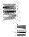
멤브레인 전기화학적 발생기의 일예는 도 1에 개략적으로 도시된다. 상기 전기화학적 발생기(1)는 필터-프레스(filter-press) 구조에 따라 상호간에 직렬로 연결되어 조립되며 부피를 최소화하기 위해 두께가 감소된 다수의 반응(reaction) 전지(2)로 구성된다.One example of a membrane electrochemical generator is shown schematically in FIG. 1. The electrochemical generator 1 is composed of a plurality of
각각의 반응 전지(2)는 일차 기상 반응제(연료)와 이차 기상 반응제(산화제)의 자유 반응 에너지를 질적 저하 없이 열 에너지 상태로 완전하게 변환시키고, 그에 따라 카르노 사이클(Carnot's cycle)의 제한을 받지 않게 된다. 연료는 상기 반응 전지(2)의 애노드 챔버(anodic chamber)에 공급되며 예를 들어 메탄올 또는 에탄올 등의 경량 알콜이나 수소를 내포하는 혼합물로 구성되고, 상기 산화제는 동일한 전지의 캐소드 챔버(cathodic chamber)에 공급되며 예를 들어, 공기 또는 산소이다. 상기 연료는 H+ 이온을 방출하는 동시에 상기 애노드 챔버에서 산화되고, 상기 산화제는 H+ 이온을 소비하여 상기 캐소드 챔버에서 환원된다. 상기 캐소드 챔버로부터 상기 애노드 챔버를 분리시키는 이온-교환 멤브레인은 전자의 통과를 차단하는 상태에서 상기 애노드 챔버로부터 상기 캐소드 챔버까지 H+ 이온의 지속적인 유동을 허용한다. 그에 따라 상기 반응 전지(2)의 전극에서 달성되는 전압은 최대로 된다.Each
보다 상세하게는, 각각의 반응 전지(2)는 한쌍의 도전성 쌍극 시트(3:bipolar sheet)에 의해 제한되고, 상기 시트들 사이에는 내측으로부터 외측까지 이온-교환 멤브레인(4), 한쌍의 다공성 전극(5), 상기 멤브레인(4)과 각각의 다공성 전극(5) 사이의 계면에 배치된 한쌍의 촉매층(6), 상기 도전성 쌍극 시트(3)들을 상기 다공성 전극(5)들에 전기적으로 접속시키는 한편 상기 기상 반응제를 분배하는 한쌍의 집전체/배전체(7), 및 상기 반응 전지(2)의 주변 부위를 밀봉하기 위한 한쌍의 밀봉 개스킷(8)이 포함된다.More specifically, each
각각의 반응 전지(2)의 상기 도전성 쌍극 시트(3)들 및/또는 상기 밀봉 개스킷(8)들에는, 도 1에는 도시되지 않은 분배 채널들에 의해 상기 애노드 및 캐소드 챔버에 연결되는 도 1에는 도시되지 않은 구멍들이 존재한다.The conductive
이러한 구멍들을 연속으로 짝을 맞추어 결합함으로써, 두개의 상부 종방향 매니폴드(9)와 두개의 하부 종방향 매니폴드(10)가 형성된다. 도 1에서는 단지 하나만이 도시된 상기 두개의 상부 종방향 매니폴드(9)는 상기 기상 반응제(연료 및 산화제)를 이송하기 위해 사용되며, 도 1에서는 단지 하나만이 도시된 상기 두개의 하부 종방향 매니폴드(10)는 선택적으로 배출물(기상 불활성 및 미변환 반응제)과 혼합되는 반응물(물; water)을 회수하기 위해 사용된다. 대안으로서, 하부 종방향 매니폴드(10)들은 이송 매니폴드로서 사용될 수 있으며, 상부 종방향 매니폴드(9)들은 배출 매니폴드로서 사용될 수 있다. 또한, 하나의 상부 종방향 매니폴드(9)를 통해, 상응하는 하부 종방향 매니폴드(10)를 배출용으로 사용하여, 두가지 기상 반응제 중 하나를 이송하고, 제 2의 하부 종방향 매니폴드(10)를 통해, 상응하는 상부 종방향 매니폴드(9)를 배출용으로 사용하여, 제 2의 기상 반응제를 이송할 수 있다.By mating these holes in succession, two upper longitudinal manifolds 9 and two lower
그후, 기상 반응제들은 분배 채널들을 통해 각각의 반응 전지(2)에 분배된다. 또한, 각각의 반응 전지(2)로부터 처리되는 반응물 및 잔여 반응제는 상기 분배 채널들을 통해 취출된다.Thereafter, the gaseous reactants are distributed to each
상기 반응 전지(2) 조립체의 외측에는, 두개의 도전성 단자 시트(11)가 제공되어 전기화학적 발생기(1)의 범위를 한정한다. 두개의 도전성 단자 시트(11) 중 하나에는 상부 및 하부 종방향 매니폴드(9, 10)의 유압식 연결을 위해 도 1에는 도시되지 않은 노즐들이 제공된다.On the outside of the
또한, 도전성 단자 시트(11)들에는 타이-로드(tie-rods)를 장착하기에 적합한 구멍들(도 1에는 도시되지 않음)이 제공되며, 상기 타이-로드에 의해 전기화학적 발생기(1)의 체결이 달성된다.In addition, the conductive terminal sheets 11 are provided with holes (not shown in FIG. 1) suitable for mounting tie-rods, by which the tie-rods of the electrochemical generator 1 are provided. Fastening is achieved.
상호간에 직렬로 연결되는 반응 전지(2)들에 의해 형성되는 전기화학적 발생기(1)는 반응 전지(2)들 중 단지 하나에만 결함이 생기는 경우에도 기능을 잃게 된다고 하는 단점을 갖는다. 결함이 있는 반응 전지(2: 이하 '결함 반응 전지'라고 함)란, 예를 들어 촉매층(6)들의 부족한 활성으로 인해 다공성 전극(5)들 중 하나가 정확하게 기능하지 않는 전지를 의미하거나, 예를 들어 부정확한 조성 또는 기계적인 특성으로 인해 과도한 전기 저항을 나타내는 바와 같이 집전체/배전체(7) 중 어느 하나가 기능하지 않는 전지를 의미하거나, 또는 멤브레인(4)이 천공되어 있는 전지를 의미한다. 마지막 경우는 상호간에 호환되지 않는 기상 반응제들을 혼합시킬 수 있다는 점에서 특히 심각하다.The electrochemical generator 1 formed by the
이러한 문제점을 극복하기 위한 공지된 해법으로서는, 상기 결함 반응 전지(2)의 외부 단락을 제공하는 유럽특허 제629015호에 개시된 방법이 있다.As a known solution for overcoming this problem, there is a method disclosed in EP 629015 which provides an external short circuit of the
상기 종래기술은 몇가지 특수한 경우에는 유리하지만, 상기 멤브레인(4)이 천공된 경우의 상기 기상 반응제들의 혼합에 관련된 발생가능한 단점들을 제거하는 것에는 실패하고 전류를 결함 반응 전지(2)로 우회시키는 것이기 때문에, 문제점을 단지 부분적으로만 해결하는 것이다. 실제로, 상기 결함 반응 전지와 상기 상부 종방향 및 하부 종방향 매니폴드(9, 10) 사이의 연결부로 인해, 상기 기상 반응제들은 결국 상기 결함 반응 전지(2)에 존재하게 된다.The prior art is advantageous in some special cases, but fails to eliminate possible drawbacks associated with mixing of the gaseous reactants when the
결과적으로, 천공된 멤브레인은 상기 전기화학적 발생기(1)의 작동을 제한할 뿐만 아니라 관련된 안전상의 문제를 야기시킨다. 미국특허 제5,876,583호에 개시된 바와 같이, 천공된 멤브레인(4)의 경우에, 상기 종래기술은 상기 결함 반응 전지(2)의 외부 단락부를 상기 전지의 유압 우회로에 결합시킬 것을 제안하고 있다.As a result, the perforated membrane not only limits the operation of the electrochemical generator 1 but also causes related safety problems. As disclosed in US Pat. No. 5,876,583, in the case of the
그러나, 상기 결함 반응 전지(2)의 외부 단락은, 상술한 작업을 수행하기 위해, 상기 도전성 쌍극 시트(3)들에 외부 돌기부들을 제공할 필요가 있다는 사실에 관련된 추가의 결점을 가지고 있다.However, the external short circuit of the
상기 외부 돌기부들을 제공하게 되면, 많은 분야에서, 특히 모바일 분야에서는 치명적인 단점인 상기 전기화학적 발생기(1)의 중량 및 부피 증가가 수반된다.Providing the external protrusions involves increasing the weight and volume of the electrochemical generator 1, which is a fatal disadvantage in many fields, especially in the mobile field.
이러한 추가적인 결점을 극복하기 위해, 다른 종래기술은 두개의 도전성 쌍극 시트(3)들 사이에 개재된 모든 구성요소들의 천공시에 전지 자체 내에 형성된 리세스 내측에 도전성 재료를 삽입함으로써 결함 반응 전지(2)의 단락을 제공하는 것을 기술하고 있다.In order to overcome this additional drawback, another prior art discloses a
그러나, 반응 전지(2)에 결함이 생길시의 바람직한 해법은 전기화학적 발생기의 완전한 전력을 회복하기 위해 상기 전기화학적 발생기(1)의 분해 후에 전지를 교체 또는 수리하는 것이다.However, a preferred solution in the event of a failure of the
그러나, 긴 작업 시간이 소요된다는 점 이외에도, 이러한 절차는 고비용을 초래하는 모든 집전체/배전체(7)의 교체 작업을 수반하게 된다. 실제로, 상기 전기화학적 발생기(1)를 조여서 압축하게 되면, 전기화학적 발생기(1)를 다시 체결할 때, 집전체/배전체(7)는 도전성 쌍극 시트(3)들 및 멤브레인-전극 조립체(4, 5)와 신뢰성 있는 전기 접촉을 더이상 제공하지 못한다.However, in addition to the long work time required, this procedure involves the replacement of all the current collectors / distributors 7 which incur high costs. Indeed, when the electrochemical generator 1 is tightened and compressed, when the electrochemical generator 1 is again fastened, the current collector / distributor 7 may be formed from the conductive
한가지 이유는 본 기술분야의 바람직한 양태의 집전체/배전체(7)가 상기 전 기화학적 발생기(1)를 분해한 후에는 원래의 크기 및 특성을 회복할 수 없다는 점이다.One reason is that the current collector / distributor 7 of the preferred embodiment of the art cannot recover its original size and properties after disassembling the electrochemical generator 1.
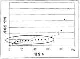
특히, 도 2에 도시된 바와 같이, 상기 반응 전지(2)에 가해진 압력에 따라, 상기 집전체/배전체(7)는 그 초기 두께의 10%의 변형에 이를 때까지 유지되는 낮은 탄성 계수를 갖는 가역적인 제 1 탄성 변형 단계를 나타낸다. 그후, 상기 집전체/배전체(7)는 긴 소성 변형 단계(초기 두께의 10 내지 60%)를 진행하고, 여기서 상기 반응 전지(2)에 가해진 압력은 실질적으로 변형 범위 내에서 일정하게 유지된다. 마지막으로, 상기 집전체/배전체(7)는 그 3차원 구조가 평평하게 되면 극도로 높은 탄성 계수를 갖는 제 2 탄성 변형 단계를 나타낸다.In particular, as shown in FIG. 2, depending on the pressure applied to the
실험에 의한 조사 결과로서, 상기 집전체/배전체(7)의 구조는 그 초기 두께의 50% 변형이 초과될 때 기계적으로 손상된다는 점이 확인되었다. 그러므로, 조립 완료시에 초기 두께의 30% 내지 40%의 소성 변형에 이르는 집전체/배전체(7)를 구비하는 것이 바람직하다. 이러한 방식에서는, 최적의 작업 조건에 가까운 균일한 접촉 압력이 상기 멤브레인-전극 조립체(4, 5)에서 안전하게 달성된다.As a result of the investigation by the experiment, it was confirmed that the structure of the current collector / distributor 7 is mechanically damaged when 50% deformation of its initial thickness is exceeded. Therefore, it is preferable to provide the current collector / distributor 7 which leads to plastic deformation of 30% to 40% of the initial thickness upon completion of assembly. In this way, a uniform contact pressure close to the optimum operating conditions is safely achieved in the membrane-
또한, 상기 소성 변형 범위 내에서 집전체/배전체(7)를 사용하게 되면, 상기 멤브레인-전극 조립체(4, 5) 및 상기 집전체/배전체에 존재할 수 있는 두께 불균일은 상기 조건에서는 제거된다는 점에서 유리하다.In addition, when the current collector / distributor 7 is used within the plastic deformation range, the thickness nonuniformity that may exist in the membrane-
다른 장점은 두께가 감소된 도전성 쌍극 시트(3)를 사용할 수 있다는 점에 있다. 실제로, 상기 조건에서는, 상기 도전성 쌍극 시트(3)들의 평면도가 떨어지더라도, 상기 멤브레인-전극 조립체(4, 5)의 상이한 부분들의 접촉 압력은 달라지지 않고 상기 집전체/배전체(7)의 변형만이 달라지게 되며, 그에 따라 상기 멤브레인-전극 조립체(4, 5)의 최적의 작업 조건이 보장된다. 이러한 사항을 고려하면, 전기화학적 발생기(1)가 분해되어도 집전체/배전체(7)는 소성 변형된 상태로 유지된다.Another advantage is that the conductive
도 3에 도시된 바와 같이, 상기 전기화학적 발생기(1)가 다시 체결되면, 상기 집전체/배전체(7)는 마치 상술한 변형 사이클을 진행하지 않았던 것처럼 다시 변형을 개시한다. 이론적으로는, 그러한 거동은 상기 집전체/배전체(7)를 재사용 가능하게 만들고, 상기 집전체/배전체에 동일한 변형을 가하면, 동일한 접촉 압력이 얻어진다. 그러나, 실제로는, 상기와 같은 방식으로 작업하게 되면, 상기 반응 전지(2)의 다양한 구성요소들 사이에서는 열악한 전기 접촉이 얻어지며, 그에 따라 국부적인 저항 증가가 초래된다. 이러한 국부적인 저항상의 결점이 발생하는 구역들은 급속하게 열화되어 내부에서 지속적으로 다량의 열이 발생되고, 결국에는 상기 멤브레인(4)의 파손에 이르게 된다.As shown in FIG. 3, when the electrochemical generator 1 is again fastened, the current collector / distributor 7 starts to deform again as if it did not go through the above-described deformation cycle. Theoretically, such behavior makes the current collector / distributor 7 reusable, and applying the same deformation to the current collector / distributor results in the same contact pressure. In practice, however, working in this manner results in poor electrical contact between the various components of the
본 발명의 목적은 상술한 결점들을 해소한 멤브레인 전기화학적 발생기의 집전체/배전체 재사용 방법을 제공하는 것이다.It is an object of the present invention to provide a current collector / distributor reuse method of a membrane electrochemical generator which overcomes the above mentioned drawbacks.
본 발명에 따르면, 멤브레인 전기화학적 발생기의 집전체/배전체 재사용 방법은 청구범위 제1항에 한정된 바와 같이 달성된다.According to the invention, the current collector / distributor reuse method of the membrane electrochemical generator is achieved as defined in claim 1.
본 발명의 보다 양호한 이해를 위해, 몇가지 실시예가 하기에 설명되며, 이들 실시예는 비제한적인 예시일 뿐이며 첨부도면을 참조로 이루어진다.For a better understanding of the invention, several embodiments are described below, which are merely non-limiting examples and are made with reference to the accompanying drawings.
도 1은 종래기술에 따른 멤브레인 전기화학적 발생기의 분해 측면도.1 is an exploded side view of a membrane electrochemical generator according to the prior art;
도 2는 도 1의 전기화학적 발생기에 존재하는 집전체/배전체에 관한 기계적인 파라미터의 변동을 도시한 도면.FIG. 2 shows variations in mechanical parameters relating to current collectors / distributors present in the electrochemical generator of FIG.
도 3은 도 1의 전기화학적 발생기에 존재하는 집전체/배전체에 관한 기계적인 파라미터의 변동을 도시한 도면.3 shows the variation of mechanical parameters relating to the current collector / distributor present in the electrochemical generator of FIG.
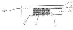
도 4는 본 발명에 따른 멤브레인 전기화학적 발생기의 제 1 실시예의 분해 측면도.4 is an exploded side view of a first embodiment of a membrane electrochemical generator according to the present invention;
도 5는 도 1의 멤브레인 전기화학적 발생기의 제 2 실시예의 분해 측면도.5 is an exploded side view of a second embodiment of the membrane electrochemical generator of FIG.
도 6a 및 도 6b는 도 1의 전기화학적 발생기의 제 3 실시예의 구성요소들을 도시한 도면.6A and 6B show components of a third embodiment of the electrochemical generator of FIG. 1.
도 7은 도 1의 멤브레인 전기화학적 발생기의 제 4 실시예의 분해 측면도.7 is an exploded side view of a fourth embodiment of the membrane electrochemical generator of FIG.
도 1을 참조하면, 집전체/배전체 재사용 방법은 전기화학적 발생기(1)에서 사용된다.Referring to FIG. 1, a current collector / distributor reuse method is used in the electrochemical generator 1.
본발명의 재사용 방법은 결함 반응 전지(2)의 존재를 검출한 후에 상기 전기화학적 발생기(1)를 분해하는 단계를 제공한다. 이어서, 본 발명의 방법은 상기 결함 반응 전지(2)를 제거하고 이전에 사용된 동일한 집전체/배전체(7)를 재사용하여 상기 전기화학적 발생기(1)를 재조립하는 단계를 제공한다.The reuse method of the present invention provides a step of disassembling the electrochemical generator 1 after detecting the presence of the
바람직하게는, 금속 스페이서, 평면 개스킷 또는 개스킷 링과 같은 전지 두 께 조절을 위한 추가 수단이 상기 전기화학적 발생기(1)를 재조립하기 전에 각각의 반응 전지(2)에 삽입된다.Preferably, further means for cell thickness control, such as metal spacers, planar gaskets or gasket rings, are inserted into each
이제, 본 발명의 방법을 비제한적인 몇가지 예를 이용하여 설명한다.The method of the present invention will now be described using some non-limiting examples.
예 1Example 1
도 4에 도시된 바와 같이, 상기 전기화학적 발생기(1)의 재조립시에, 적절한 두께의 금속성 요소(12)가 상기 도전성 쌍극 시트(3)와 개별적인 재사용된 집전체/배전체(7) 사이의 각각의 반응 전지(2) 상의 애노드측 및 캐소드측에 전지 두께 조절 수단으로서 삽입된다. 이러한 방식에서, 상기 전기화학적 발생기(1)의 후속 체결 과정에서, 상기 재사용된 집전체/배전체(7)는 상기 전기화학적 발생기(1)의 일차적인 체결 도중에 상기 집전체/배전체에 이미 제공된 변형을 의미하는 추가의 소성 변형을 진행하도록 강제된다. 상기 조건에서, 상기 집전체/배전체(7)의 기계적인 특성(도 3 참조)은 상기 집전체/배전체가 상기 멤브레인-전극 조립체(4, 5)의 최적의 작동 압력을 보장하는 최초의 이용상태에서처럼 거동하게 한다.As shown in FIG. 4, upon reassembly of the electrochemical generator 1, a
특히, 상기 금속성 요소(12)는 금속성 메시(mesh)로 구성되거나, 대안적으로 금속성 피륙 또는 직물, 인터워븐(interwoven) 섬유, 다공질(foraminous) 시트 또는 팽창(expanded) 시트로 구성될 수 있다.In particular, the
특히, 상기 금속성 요소(12)의 두께는, 상술된 바와 같이 상기 집전체/배전체(7)의 구조가 손상되는 한도인 50% 이하의 전체 변형(즉, 상기 집전체/배전체의 원래 두께에 대해서 계산)을 상기 재사용된 집전체/배전체(7)에 부가하는 바와 같이 계산되어야 한다.In particular, the thickness of the
실험에 의한 조사결과로부터 알 수 있듯이, 상기 전기화학적 발생기(1)의 각각의 재조립에 대해서, 상기 도전성 쌍극 시트(3)들, 상기 금속성 요소(12), 상기 재사용된 집전체/배전체(7) 및 상기 멤브레인-전극 조립체(4, 5) 사이에 양호한 전기 접촉을 달성하기 위해서는, 상기 재사용된 집전체/배전체(7)의 변형을 그 초기 두께의 적어도 3% 증가시키면 충분하다. 상기 방식에서, 상기 금속성 요소(12)들을 적절한 두께로 유지하면서, 동일한 집전체/배전체(7)를 여러 번 사용하는 유지 개입(maintenance interventions)을 하기 위해 상기 전기화학적 발생기(1)를 분해 후에 재조립하는 것이 가능하다.As can be seen from the experimental results, for each reassembly of the electrochemical generator 1, the conductive
예를 들어, 3㎜의 초기 두께를 갖는 집전체/배전체(7)와 상기 전기화학적 발생기(1)에 각각 재조립할 때 0.2㎜까지 증가되는 0.2㎜의 초기 두께를 갖는 금속성 메시들을 사용하면, 상기 동일한 집전체/배전체(7)를 추가로 4회나 사용할 수 있는 상기 전기화학적 발생기(1)의 재조립 가능성이 존재한다.For example, using metallic meshes having an initial thickness of 0.2 mm increased to 0.2 mm when reassembled to the current collector / distributor 7 and the electrochemical generator 1 each having an initial thickness of 3 mm, There is a possibility of reassembly of the electrochemical generator 1 which can use the same current collector / distributor 7 four more times.
보다 상세하게는,More specifically,
- 변형되지 않은 집전체/배전체(7)의 두께: 3㎜;Thickness of current collector / distributor 7 not deformed: 3 mm;
ㆍ 조립Assembly
- 집전체/배전체(7)의 두께: 그 초기 두께의 20%의 변형에 대응하는 2.4㎜Thickness of current collector / distributor 7: 2.4 mm corresponding to a deformation of 20% of its initial thickness
ㆍ 1차 재조립(0.2㎜의 두께를 갖는 금속성 메시를 사용)Primary reassembly (using metallic mesh with a thickness of 0.2 mm)
- 집전체/배전체(7)의 두께: 그 초기 두께의 27%의 변형에 대응하는 2.2㎜Thickness of current collector / distributor 7: 2.2 mm corresponding to a deformation of 27% of its initial thickness
ㆍ 2차 재조립(0.4㎜의 두께를 갖는 금속성 메시를 사용)Secondary reassembly (using metallic mesh with a thickness of 0.4 mm)
- 집전체/배전체(7)의 두께: 그 초기 두께의 33%의 변형에 대응하는 2㎜Thickness of current collector / distributor 7: 2 mm corresponding to a deformation of 33% of its initial thickness
ㆍ 3차 재조립(0.6㎜의 두께를 갖는 금속성 메시를 사용)3rd reassembly (using metallic mesh with a thickness of 0.6 mm)
- 집전체/배전체(7)의 두께: 그 초기 두께의 40%의 변형에 대응하는 1.8㎜Thickness of current collector / distributor 7: 1.8 mm corresponding to a deformation of 40% of its initial thickness
ㆍ 4차 재조립(0.8㎜의 두께를 갖는 금속성 메시를 사용)4th reassembly (using metallic mesh with a thickness of 0.8 mm)
- 집전체/배전체(7)의 두께: 그 초기 두께의 47%의 변형에 대응하는 1.6㎜Thickness of current collector / distributor 7: 1.6 mm corresponding to 47% of its initial thickness
상기 금속성 요소(12)의 구조 재료는 선택적으로 상기 집전체/배전체(7)의 재료와 동일한 재료로, 또는 상기 도전성 쌍극 시트(3)와 동일한 재료로, 또는 제 3의 재료로 이루어질 수 있다. 특히, 사용되는 재료의 형태는, 상기 금속성 요소(12)들, 상기 도전성 쌍극 시트(3)들 및 상기 집전체/배전체(7) 사이의 양호한 전기 접촉을 유지하기 위해 상기 금속성 요소 자체의 내부식성을 고려하여 매회 평가되어야 한다. 통상적으로 사용되는 재료로는 스틸, 알루미늄 및 그 합금, 티타늄, 니켈 및 그 합금 등이 있다. 몇가지 경우에, 이들 재료는 상이한 구성요소들간의 접촉 저항을 경감시키고 상기 금속성 요소(12)의 내부식성을 개선하기 위해 표면처리될 수 있다.The structural material of the
예 2Example 2
도 5에 도시된 바와 같이, 상기 전기화학적 발생기(1)의 재조립시에, 상기 밀봉 개스킷(8)은, 상기 멤브레인-전극 조립체(4, 5) 및 상기 도전성 쌍극 시트(3)와의 양호한 전기 접촉을 보장하기 위해 상기 전기화학적 발생기(1)의 재조립 도중에 상기 집전체/배전체(7)에 충분한 소성 변형을 가할 수 있을 정도로만 상기 밀봉 개스킷(8)의 두께보다 작은 두께를 갖는 박형의 밀봉 개스킷(13)으로 교체된다. 특히, 상기 집전체/배전체(7)의 변형을 그 초기 두께의 적어도 3% 증가시키면 충분하다. 예를 들어, 다소 통상적인 치수인 2.1㎜ 두께의 밀봉 개스킷(8)을 사용하면, 상기 박형의 밀봉 개스킷(13)은 적어도 0.1 내지 0.2㎜ 작은 두께를 가져야 한다.As shown in FIG. 5, upon reassembly of the electrochemical generator 1, the sealing gasket 8 is in good electrical contact with the membrane-
예 3Example 3
전기화학적 발생기(1)가 열가소성 재료로 제조된 밀봉 개스킷(14)을 구비하고 또한 상기 밀봉 개스킷의 표면(14a)에서 소성 변형을 진행할 수 있는 밀봉 링(15)들을 구비하면, 동일한 전기화학적 발생기의 재조립시에, 체결 압력을 약간 증가시킴으로써 멤브레인-전극 조립체(4, 5) 및 도전성 쌍극 시트(3)와의 양호한 전기 접촉을 달성하기에 충분한 정도(예를 들어, 초기 두께의 3% 이상의 값까지)로만 집전체/배전체(7)를 변형시킬 수 있다. 실제로, 상기 전기화학적 발생기(1)가 체결되면, 상기 밀봉 링(15)들만이 상기 도전성 쌍극 시트(3)들에 접촉하게 된다. 변형시에, 상기 밀봉 링(15)들은 기상 반응제들의 밀봉을 보장할 수 있다.If the electrochemical generator 1 has a sealing gasket 14 made of thermoplastic material and also has sealing
도 6a에 보다 상세하게 도시된 바와 같이, 상기 전기화학적 발생기(1)의 제 1 체결 단계 도중에는, 상기 밀봉 링(15)들은 완전하게 변형되지는 않기 때문에, 상기 도전성 쌍극 시트(3)들과 상기 멤브레인-전극 조립체(4, 5) 사이의 거리는 상기 전기화학적 발생기(1)의 제 2 체결 단계(도 6b 참조)에서보다는 크며, 상기 밀봉 링(15)들 및 상기 집전체/배전체(7)는 보다 큰 변형을 진행하도록 가압된다.As shown in more detail in FIG. 6A, during the first fastening step of the electrochemical generator 1, since the sealing rings 15 are not completely deformed, the conductive
상기 밀봉 링(15)들은, 보다 적절하게 상기 기상 반응제들의 누출을 방지하며 상기 개스킷 재료(예를 들어, 실리콘, 고무)보다 더욱 변형하기 쉬운 상이한 중첩 재료로 제조될 수 있거나, 상기 밀봉 개스킷(14)과 함께 스탬핑될 수 있다.The sealing rings 15 may be made of different overlapping materials, more suitably to prevent leakage of the gaseous reactants and more susceptible to deformation than the gasket material (eg silicone, rubber), or the sealing gasket ( 14) can be stamped together.
예 4Example 4
상기 전기화학적 발생기(1)의 재조립시에, 상기 밀봉 개스킷(8)들이 낮은 탄성 계수를 갖는 탄성 재료로 제조되는 경우에만 기계적으로 강성인 구조를 갖는 집전체/배전체(7)를 재사용할 수 있게 된다. 실제로, 이러한 경우에만, 전체적으로 가해진 압력은 대부분 상기 집전체/배전체(7)상에 분포되며 상기 밀봉 개스킷(8)에는 매우 적은 범위로만 분포되므로, 상기 각각의 반응 전지(2)의 최적의 작동값을 얻기 위해 상기 멤브레인-전극 조립체(4, 5)의 압축이 변경할 가능성이 증가된다. 강성 형태의 집전체/배전체(7)는 금속성 폼(foams), 소결 재료, 금속성 메시 또는 팽창 시트로 이루어지며, 상기 밀봉 개스킷(8)의 제조에 적합한 구조 재료는 본질적으로, EPDM, 니트릴 부타디엔 고무(NBR), 불화 제품, Santoprene

마지막으로, 본 발명의 범위로부터 일탈함이 없이 상술한 방법에 대해서 일부 변형 및 변경이 취해질 수 있다는 것은 자명하다.Finally, it will be apparent that some variations and modifications may be made to the method described above without departing from the scope of the present invention.
예를 들어, 본 발명의 방법이 단순히 반응 전지(2)들을 포함하는 전기화학적 발생기(1)에서 사용하기 위한 것으로 설명되었지만, 상기 방법은 도 7에 도시된 바와 같이 임의 쌍의 반응 전지(2)들 사이에 냉각(cooling) 전지(21)들이 개재된 전 기화학적 발생기(20)에도 동일하게 적용될 수 있으며, 여기서 상기 전기화학적 발생기(20)의 다양한 부분들에는 도 1에 사용된 것과 동일한 참조번호들이 사용된다. 상기 냉각 전지(21)들은 상기 이온-교환 멤브레인(4), 다공성 전극(5) 및 촉매층(6)으로 구성되는 전기화학적 패키지를 포함하지 않는다는 점을 제외하고는 상기 반응 전지(2)와 동일하다.For example, although the method of the present invention has been described for use in an electrochemical generator 1 that simply includes the
이러한 경우에, 본 발명의 방법을 사용하게 되면, 상기 냉각 전지(21)들의 집전체/배전체(22)는 상기 전기화학적 발생기(20)의 후속 재조립에서 재사용될 수 있다.In this case, using the method of the present invention, the current collector /
대안으로서, 냉각 전지(21)들에서만, 탄성 특성을 갖는 집전체/배전체(22)가 사용될 수 있다. 이러한 경우에, 본 발명의 방법은, 영구 변형을 진행하지 않는 상기 냉각 전지(21)에 존재하는 집전체/배전체(22)가 상기와 같이 재사용될 수 있을 때 반응 전지(2)에 존재하는 집전체/배전체(7)에만 적용될 것이다.As an alternative, in the
Claims (30)
Translated fromKoreanApplications Claiming Priority (2)
| Application Number | Priority Date | Filing Date | Title |
|---|---|---|---|
| ITMI2001A002342 | 2001-11-08 | ||
| IT2001MI002342AITMI20012342A1 (en) | 2001-11-08 | 2001-11-08 | METHOD FOR REUSING COLLECTORS / CURRENT DISTRIBUTORS OF A DIAPHRAGM ELECTROCHEMICAL GENERATOR |
Publications (2)
| Publication Number | Publication Date |
|---|---|
| KR20050044360A KR20050044360A (en) | 2005-05-12 |
| KR100916183B1true KR100916183B1 (en) | 2009-09-08 |
Family
ID=11448579
Family Applications (1)
| Application Number | Title | Priority Date | Filing Date |
|---|---|---|---|
| KR1020047006937AExpired - LifetimeKR100916183B1 (en) | 2001-11-08 | 2002-11-08 | Current collector / distributor reuse method of membrane electrochemical generator |
Country Status (15)
| Country | Link |
|---|---|
| US (1) | US7294428B2 (en) |
| EP (1) | EP1444749B1 (en) |
| JP (1) | JP4959109B2 (en) |
| KR (1) | KR100916183B1 (en) |
| CN (1) | CN1579034A (en) |
| AT (1) | ATE298935T1 (en) |
| AU (1) | AU2002351929A1 (en) |
| BR (1) | BR0213976A (en) |
| CA (1) | CA2466369C (en) |
| DE (1) | DE60204908T2 (en) |
| DK (1) | DK1444749T3 (en) |
| ES (1) | ES2243781T3 (en) |
| IT (1) | ITMI20012342A1 (en) |
| TW (1) | TW200408158A (en) |
| WO (1) | WO2003041205A2 (en) |
Families Citing this family (7)
| Publication number | Priority date | Publication date | Assignee | Title |
|---|---|---|---|---|
| US6989214B2 (en) | 2002-11-15 | 2006-01-24 | 3M Innovative Properties Company | Unitized fuel cell assembly |
| CN1536698B (en)* | 2003-04-02 | 2010-12-15 | 松下电器产业株式会社 | Electrolyte film structure for fuel cell, MEA structure and fuel cell |
| US7358005B2 (en)* | 2003-09-18 | 2008-04-15 | General Electric Company | Methods and apparatus for isolating solid oxide fuel cells |
| KR100916394B1 (en)* | 2007-09-05 | 2009-09-07 | 현대자동차주식회사 | Modular Structure of Stack for Fuel Cell Vehicle |
| CN102754261B (en) | 2009-12-22 | 2015-06-17 | 托普索燃料电池股份有限公司 | Manufacturing and calibration process for interconnects of fuel cells or fuel cell stacks |
| US10305135B2 (en) | 2016-02-02 | 2019-05-28 | Honda Motor Co., Ltd. | Method of producing fuel cell stack and method of producing metal separator for fuel cell |
| JP6368807B2 (en)* | 2016-02-02 | 2018-08-01 | 本田技研工業株式会社 | Manufacturing method of fuel cell stack and manufacturing method of metal separator for fuel cell |
Citations (3)
| Publication number | Priority date | Publication date | Assignee | Title |
|---|---|---|---|---|
| JPS63236268A (en)* | 1987-03-25 | 1988-10-03 | Hitachi Ltd | Fuel cell |
| JPH06310161A (en)* | 1993-04-28 | 1994-11-04 | Mitsubishi Electric Corp | Fuel cell protection method, protection device, and fuel cell device |
| KR19980081284A (en)* | 1997-04-11 | 1998-11-25 | 다까노야스아끼 | Fuel cell |
Family Cites Families (6)
| Publication number | Priority date | Publication date | Assignee | Title |
|---|---|---|---|---|
| JP3135991B2 (en)* | 1992-06-18 | 2001-02-19 | 本田技研工業株式会社 | Fuel cell and fuel cell stack tightening method |
| IT1270878B (en)* | 1993-04-30 | 1997-05-13 | Permelec Spa Nora | IMPROVED ELECTROCHEMISTRY CELL USING ION EXCHANGE MEMBRANES AND METAL BIPOLAR PLATES |
| US5454925A (en)* | 1994-05-03 | 1995-10-03 | Eltech Systems Corporation | Repair of mesh electrode spaced from electrode pan |
| US5958211A (en)* | 1995-02-10 | 1999-09-28 | De Nora S.P.A. | Method of reactivating an electrolyzer |
| JPH09259917A (en)* | 1996-03-21 | 1997-10-03 | Mitsubishi Electric Corp | Molten carbonate fuel cell and method of manufacturing the same |
| IT1284887B1 (en)* | 1996-10-03 | 1998-05-22 | De Nora Spa | METHOD OF EXCLUSION OF A MALFUNCTIONING ELEMENTARY CELL OF AN ELECTROLYZER OR OF A MEMBRANE ELECTROCHEMICAL GENERATOR |
- 2001
- 2001-11-08ITIT2001MI002342Apatent/ITMI20012342A1/enunknown
- 2002
- 2002-11-01TWTW91132344Apatent/TW200408158A/enunknown
- 2002-11-08EPEP02787613Apatent/EP1444749B1/ennot_activeExpired - Lifetime
- 2002-11-08KRKR1020047006937Apatent/KR100916183B1/ennot_activeExpired - Lifetime
- 2002-11-08DKDK02787613Tpatent/DK1444749T3/enactive
- 2002-11-08DEDE60204908Tpatent/DE60204908T2/ennot_activeExpired - Lifetime
- 2002-11-08USUS10/493,930patent/US7294428B2/ennot_activeExpired - Lifetime
- 2002-11-08CNCNA02821742XApatent/CN1579034A/enactivePending
- 2002-11-08JPJP2003543131Apatent/JP4959109B2/ennot_activeExpired - Lifetime
- 2002-11-08BRBR0213976-6Apatent/BR0213976A/ennot_activeIP Right Cessation
- 2002-11-08WOPCT/EP2002/012516patent/WO2003041205A2/enactiveIP Right Grant
- 2002-11-08ATAT02787613Tpatent/ATE298935T1/ennot_activeIP Right Cessation
- 2002-11-08AUAU2002351929Apatent/AU2002351929A1/ennot_activeAbandoned
- 2002-11-08CACA2466369Apatent/CA2466369C/ennot_activeExpired - Lifetime
- 2002-11-08ESES02787613Tpatent/ES2243781T3/ennot_activeExpired - Lifetime
Patent Citations (3)
| Publication number | Priority date | Publication date | Assignee | Title |
|---|---|---|---|---|
| JPS63236268A (en)* | 1987-03-25 | 1988-10-03 | Hitachi Ltd | Fuel cell |
| JPH06310161A (en)* | 1993-04-28 | 1994-11-04 | Mitsubishi Electric Corp | Fuel cell protection method, protection device, and fuel cell device |
| KR19980081284A (en)* | 1997-04-11 | 1998-11-25 | 다까노야스아끼 | Fuel cell |
Also Published As
| Publication number | Publication date |
|---|---|
| JP2005510832A (en) | 2005-04-21 |
| DE60204908T2 (en) | 2006-05-04 |
| CN1579034A (en) | 2005-02-09 |
| TW200408158A (en) | 2004-05-16 |
| CA2466369A1 (en) | 2003-05-15 |
| KR20050044360A (en) | 2005-05-12 |
| US7294428B2 (en) | 2007-11-13 |
| EP1444749A2 (en) | 2004-08-11 |
| DE60204908D1 (en) | 2005-08-04 |
| CA2466369C (en) | 2013-04-09 |
| ATE298935T1 (en) | 2005-07-15 |
| ITMI20012342A1 (en) | 2003-05-08 |
| WO2003041205A2 (en) | 2003-05-15 |
| AU2002351929A1 (en) | 2003-05-19 |
| EP1444749B1 (en) | 2005-06-29 |
| BR0213976A (en) | 2004-08-31 |
| WO2003041205A3 (en) | 2003-09-18 |
| JP4959109B2 (en) | 2012-06-20 |
| DK1444749T3 (en) | 2005-10-24 |
| US20040241533A1 (en) | 2004-12-02 |
| ES2243781T3 (en) | 2005-12-01 |
Similar Documents
| Publication | Publication Date | Title |
|---|---|---|
| CA2401915C (en) | Polymer elecrolyte fuel cell | |
| US6706436B2 (en) | Electrochemical cell design using a bipolar plate | |
| EP0988655B1 (en) | A fuel cell assembly | |
| DE69716351T2 (en) | Electrochemical membrane cell with gas diffusion electrodes that are in contact with porous, flat metal current collectors with highly distributed contact surfaces | |
| US20250243590A1 (en) | Frame for pem electrolysis cells and pem electrolysis cell stack for generating high-pressure hydrogen by means of differential pressure electrolysis | |
| US6884537B2 (en) | Structural seal for a fuel cell | |
| US20090114531A1 (en) | Electrochemical Cell Stack | |
| US20040224212A1 (en) | Fuel cell | |
| CN101331632B (en) | Fuel cell and gasket | |
| KR20030081499A (en) | Method of short-circuiting a malfunctioning elementary electrochemical cell of a filter-press structure | |
| KR100916183B1 (en) | Current collector / distributor reuse method of membrane electrochemical generator | |
| CN220767190U (en) | Electrolytic stack assembly and electrolytic tank comprising same | |
| US20060127736A1 (en) | Fuel cell seal with integral bridge | |
| CN110311150A (en) | The manufacturing method of fuel cell monopole and bipolar plates | |
| KR100417050B1 (en) | Polymer electrolyte fuel cell | |
| US20250129492A1 (en) | Electrolyzer stacks, electrolysis systems, and methods for operating electrolysis systems | |
| WO2025020041A1 (en) | Basic frame and electrochemical energy module | |
| AU7631398A (en) | A fuel cell assembly |
Legal Events
| Date | Code | Title | Description |
|---|---|---|---|
| PA0105 | International application | Patent event date:20040507 Patent event code:PA01051R01D Comment text:International Patent Application | |
| PG1501 | Laying open of application | ||
| A201 | Request for examination | ||
| PA0201 | Request for examination | Patent event code:PA02012R01D Patent event date:20071023 Comment text:Request for Examination of Application | |
| E902 | Notification of reason for refusal | ||
| PE0902 | Notice of grounds for rejection | Comment text:Notification of reason for refusal Patent event date:20081212 Patent event code:PE09021S01D | |
| E701 | Decision to grant or registration of patent right | ||
| PE0701 | Decision of registration | Patent event code:PE07011S01D Comment text:Decision to Grant Registration Patent event date:20090601 | |
| GRNT | Written decision to grant | ||
| PR0701 | Registration of establishment | Comment text:Registration of Establishment Patent event date:20090901 Patent event code:PR07011E01D | |
| PR1002 | Payment of registration fee | Payment date:20090902 End annual number:3 Start annual number:1 | |
| PG1601 | Publication of registration | ||
| FPAY | Annual fee payment | Payment date:20120827 Year of fee payment:4 | |
| PR1001 | Payment of annual fee | Payment date:20120827 Start annual number:4 End annual number:4 | |
| FPAY | Annual fee payment | Payment date:20130822 Year of fee payment:5 | |
| PR1001 | Payment of annual fee | Payment date:20130822 Start annual number:5 End annual number:5 | |
| FPAY | Annual fee payment | Payment date:20140821 Year of fee payment:6 | |
| PR1001 | Payment of annual fee | Payment date:20140821 Start annual number:6 End annual number:6 | |
| FPAY | Annual fee payment | Payment date:20150820 Year of fee payment:7 | |
| PR1001 | Payment of annual fee | Payment date:20150820 Start annual number:7 End annual number:7 | |
| FPAY | Annual fee payment | Payment date:20160818 Year of fee payment:8 | |
| PR1001 | Payment of annual fee | Payment date:20160818 Start annual number:8 End annual number:8 | |
| FPAY | Annual fee payment | Payment date:20170727 Year of fee payment:9 | |
| PR1001 | Payment of annual fee | Payment date:20170727 Start annual number:9 End annual number:9 | |
| FPAY | Annual fee payment | Payment date:20190801 Year of fee payment:11 | |
| PR1001 | Payment of annual fee | Payment date:20190801 Start annual number:11 End annual number:11 | |
| PR1001 | Payment of annual fee | Payment date:20210721 Start annual number:13 End annual number:13 | |
| PR1001 | Payment of annual fee | Payment date:20220802 Start annual number:14 End annual number:14 | |
| PC1801 | Expiration of term | Termination date:20230508 Termination category:Expiration of duration |