KR100913089B1 - Method for Transmitting Pilot for Multiple Carrier System - Google Patents
Method for Transmitting Pilot for Multiple Carrier SystemDownload PDFInfo
- Publication number
- KR100913089B1 KR100913089B1KR1020060047151AKR20060047151AKR100913089B1KR 100913089 B1KR100913089 B1KR 100913089B1KR 1020060047151 AKR1020060047151 AKR 1020060047151AKR 20060047151 AKR20060047151 AKR 20060047151AKR 100913089 B1KR100913089 B1KR 100913089B1
- Authority
- KR
- South Korea
- Prior art keywords
- pilot
- transmitted
- data
- type pilot
- subframe
- Prior art date
- Legal status (The legal status is an assumption and is not a legal conclusion. Google has not performed a legal analysis and makes no representation as to the accuracy of the status listed.)
- Active
Links
Images


Classifications
- H—ELECTRICITY
- H04—ELECTRIC COMMUNICATION TECHNIQUE
- H04L—TRANSMISSION OF DIGITAL INFORMATION, e.g. TELEGRAPHIC COMMUNICATION
- H04L5/00—Arrangements affording multiple use of the transmission path
- H04L5/003—Arrangements for allocating sub-channels of the transmission path
- H04L5/0048—Allocation of pilot signals, i.e. of signals known to the receiver
- H—ELECTRICITY
- H04—ELECTRIC COMMUNICATION TECHNIQUE
- H04L—TRANSMISSION OF DIGITAL INFORMATION, e.g. TELEGRAPHIC COMMUNICATION
- H04L25/00—Baseband systems
- H04L25/02—Details ; arrangements for supplying electrical power along data transmission lines
- H04L25/0202—Channel estimation
- H04L25/0224—Channel estimation using sounding signals
- H04L25/0226—Channel estimation using sounding signals sounding signals per se
- H—ELECTRICITY
- H04—ELECTRIC COMMUNICATION TECHNIQUE
- H04L—TRANSMISSION OF DIGITAL INFORMATION, e.g. TELEGRAPHIC COMMUNICATION
- H04L25/00—Baseband systems
- H04L25/02—Details ; arrangements for supplying electrical power along data transmission lines
- H04L25/0202—Channel estimation
- H04L25/0224—Channel estimation using sounding signals
- H04L25/0228—Channel estimation using sounding signals with direct estimation from sounding signals
- H—ELECTRICITY
- H04—ELECTRIC COMMUNICATION TECHNIQUE
- H04L—TRANSMISSION OF DIGITAL INFORMATION, e.g. TELEGRAPHIC COMMUNICATION
- H04L27/00—Modulated-carrier systems
- H04L27/26—Systems using multi-frequency codes
- H04L27/2601—Multicarrier modulation systems
- H04L27/2602—Signal structure
- H04L27/261—Details of reference signals
- H04L27/2613—Structure of the reference signals
- H04L27/26134—Pilot insertion in the transmitter chain, e.g. pilot overlapping with data, insertion in time or frequency domain
- H—ELECTRICITY
- H04—ELECTRIC COMMUNICATION TECHNIQUE
- H04L—TRANSMISSION OF DIGITAL INFORMATION, e.g. TELEGRAPHIC COMMUNICATION
- H04L27/00—Modulated-carrier systems
- H04L27/26—Systems using multi-frequency codes
- H04L27/2601—Multicarrier modulation systems
- H04L27/2614—Peak power aspects
- H04L27/262—Reduction thereof by selection of pilot symbols
- H—ELECTRICITY
- H04—ELECTRIC COMMUNICATION TECHNIQUE
- H04L—TRANSMISSION OF DIGITAL INFORMATION, e.g. TELEGRAPHIC COMMUNICATION
- H04L5/00—Arrangements affording multiple use of the transmission path
- H04L5/0001—Arrangements for dividing the transmission path
- H04L5/0014—Three-dimensional division
- H04L5/0016—Time-frequency-code
- H—ELECTRICITY
- H04—ELECTRIC COMMUNICATION TECHNIQUE
- H04W—WIRELESS COMMUNICATION NETWORKS
- H04W72/00—Local resource management
- H04W72/04—Wireless resource allocation
- H04W72/044—Wireless resource allocation based on the type of the allocated resource
- H04W72/0446—Resources in time domain, e.g. slots or frames
- H—ELECTRICITY
- H04—ELECTRIC COMMUNICATION TECHNIQUE
- H04W—WIRELESS COMMUNICATION NETWORKS
- H04W72/00—Local resource management
- H04W72/04—Wireless resource allocation
- H04W72/044—Wireless resource allocation based on the type of the allocated resource
- H04W72/0453—Resources in frequency domain, e.g. a carrier in FDMA
- H—ELECTRICITY
- H04—ELECTRIC COMMUNICATION TECHNIQUE
- H04W—WIRELESS COMMUNICATION NETWORKS
- H04W88/00—Devices specially adapted for wireless communication networks, e.g. terminals, base stations or access point devices
- H04W88/02—Terminal devices
- H—ELECTRICITY
- H04—ELECTRIC COMMUNICATION TECHNIQUE
- H04W—WIRELESS COMMUNICATION NETWORKS
- H04W88/00—Devices specially adapted for wireless communication networks, e.g. terminals, base stations or access point devices
- H04W88/08—Access point devices
Landscapes
- Engineering & Computer Science (AREA)
- Signal Processing (AREA)
- Computer Networks & Wireless Communication (AREA)
- Power Engineering (AREA)
- Mobile Radio Communication Systems (AREA)
- Digital Transmission Methods That Use Modulated Carrier Waves (AREA)
Abstract
Translated fromKoreanDescription
Translated fromKorean도 1 은 DFT-S-OFDM 방식의 전송기를 나타낸 일실시예 구성도.1 is a diagram illustrating an embodiment of a transmitter of a DFT-S-OFDM scheme.
도 2 는 코드 분할 다중화(Code Division Multiplexing)를 이용한 파일럿 전송 방법을 나타낸 일실시예 설명도.2 is a diagram illustrating an embodiment of a pilot transmission method using code division multiplexing.
도 3a ~ 도 3d 는 주파수 분할 다중화(Frequency Division Multiplexing)를 이용한 파일럿 전송 방법을 나타낸 일실시예 설명도.3A to 3D are diagrams illustrating an embodiment of a pilot transmission method using frequency division multiplexing.
도 4a 및 도 4b 는 코드 분할 다중과 주파수 분할 다중을 결합한 파일럿 신호 전송 방식을 나타낸 일실시예 설명도.4A and 4B are exemplary diagrams illustrating a pilot signal transmission method combining code division multiplexing and frequency division multiplexing.
도 5a 및 도 5b 는 시간 분할 다중화(Time Division Multiplexing)를 이용한 파일럿 신호 전송 방식을 나타낸 일실시예 설명도.5A and 5B are exemplary diagrams illustrating a pilot signal transmission method using time division multiplexing.
도 6a 및 도 6b 는 서브 프레임 단위의 시분할 방식을 나타낸 일실시예 설명도.6A and 6B are diagrams illustrating an embodiment of time division in subframe units;
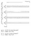
도 7a 및 도 7b 는 하나의 서브 프레임 내에서 UE 가 데이터와 CQ 파일럿을 동시에 전송할 때 2차 파일럿을 전송하는 방법을 나타낸 일실시예 설명도.7A and 7B illustrate an embodiment of a method of transmitting a secondary pilot when a UE simultaneously transmits data and a CQ pilot in one subframe.
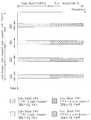
도 8 은 데이터 전송 시 채널 추정을 위한 2 차 파일럿이 기본적으로 전송되어야 하고, 시 분할 방식으로 UE가 CQ 파일럿을 전송하는 경우, CQ 파일럿을 전송하지 않는 타이밍에서 데이터를 전송할 때 2차 파일럿 전송 방식을 나타낸 일실시예 설명도.FIG. 8 illustrates that a secondary pilot for channel estimation should be basically transmitted during data transmission, and when the UE transmits a CQ pilot in a time division scheme, the second pilot transmission scheme when transmitting data at a timing not transmitting a CQ pilot Illustrative diagram of one embodiment shown.
본 발명은 다중 반송파 시스템에 적용되는 파일럿 신호 전송 방법 방법에 관한 것으로써, 보다 상세하게는, 2 이상의 이동국이 파일럿 신호를 전송하는 경우, 파일럿 신호를 다중화 하여 전송하기 위한 방법에 관한 것이다.The present invention relates to a method for transmitting a pilot signal applied to a multi-carrier system, and more particularly, to a method for multiplexing and transmitting a pilot signal when two or more mobile stations transmit a pilot signal.
다중 반송파를 이용한 시스템의 통신 방법의 일례로서, 직교 주파수 분할 다중화 (Orthogonal Frequency Division Multiplexing; 이하 'OFDM') 방식과 DFT-S-OFDM (DFT Spreading OFDM) 방식 및 직교 주파수 분할 다중접속 (Orthogonal Frequency Division Multiple Access; 이하 'OFDMA')의 일례를 설명한다.As an example of a communication method of a system using multiple carriers, Orthogonal Frequency Division Multiplexing (OFDM), DFT-S-OFDM (DFT Spreading OFDM), and Orthogonal Frequency Division Multiple Access (OFDMA)) will be described below.
OFDM의 기본원리는 고속 전송률(high-rate)을 갖는 데이터 열(data stream)을 낮은 전송률(slow-rate)를 갖는 많은 수의 데이터 열로 나누고, 이들을 다수의 반송파를 사용하여 동시에 전송하는 것이다. 상기 다수의 반송파 각각을 부 반송파(subcarrier)라 한다. 상기 OFDM 의 다수의 반송파 사이에 직교성(orthogonality)이 존재하기 때문에, 반송파의 주파수 성분은 상호 중첩되어도 수신 단에서의 검출이 가능하다. 상기 고속 전송률을 갖는 데이터 열은, 직/병렬 변환부(Serial to Parallel converter)를 통해 다수의 낮은 전송률의 데이터 열(data stream)로 변환되고, 상기 병렬로 변환된 다수의 데이터 열에 각각의 부 반송파가 곱해진 후 각각의 데이터 열이 합해져서 수신 단으로 전송된다.The basic principle of OFDM is to divide a high-rate data stream into a large number of low-rate data streams and transmit them simultaneously using multiple carriers. Each of the plurality of carriers is called a subcarrier. Since orthogonality exists between the multiple carriers of the OFDM, the frequency components of the carriers can be detected at the receiving end even if they overlap each other. The high data rate data stream is converted into a plurality of low data rate data streams through a serial to parallel converter, and each subcarrier is included in the parallel data streams. After multiplying, the respective data strings are summed and sent to the receiving end.
직/병렬 변환부에 의해 생성된 다수의 병렬 데이터 스트림은, 역 이산 푸리에 변환(Inverse Discrete Fourier Transform; 이하 'IDFT')에 의하여 다수의 부 반송파를 이용하여 전송될 수 있으며, 상기 IDFT는 역 고속 푸리에 변환(IFFT; Inverse Fast Fourier Transform)을 사용하여 효율적으로 구현될 수 있다.A plurality of parallel data streams generated by the serial / parallel transform unit may be transmitted using a plurality of subcarriers by an inverse discrete fourier transform (IDFT), and the IDFT is inverse fast. It can be efficiently implemented using the Inverse Fast Fourier Transform (IFFT).
낮은 전송률을 갖는 부 반송파의 심볼 구간(symbol duration)은 증가하게 되므로 다중경로 지연확산에 의해 발생하는 시간상에서의 상대적인 신호 분산(dispersion)이 감소한다. 한편, OFDM 심볼 사이에 채널의 지연 확산보다 긴 보호구간(guard interval)을 삽입하여 심볼간 간섭(Inter-Symbol Interference)을 줄일 수 있다. 또한, 보호구간에 OFDM 신호의 일부를 복사하여 심볼의 시작부분에 배치하면 OFDM 심볼은 순환적으로 확장(cyclically extended)되어 심볼을 보호할 수 있다.Since the symbol duration of the low carrier subcarrier is increased, relative signal dispersion in time caused by multipath delay spread is reduced. Meanwhile, inter-symbol interference may be reduced by inserting a guard interval longer than a delay spread of a channel between OFDM symbols. In addition, if a part of the OFDM signal is copied to the guard interval and placed at the beginning of the symbol, the OFDM symbol may be cyclically extended to protect the symbol.
DFT-S-OFDM 방식(또는 SC-FDMA(Single Carrier-FDMA))을 설명하면 다음과 같다. SC-FDMA 방식은 상향링크에 주로 적용되는 방식으로 OFDM 신호를 생성하기 전에 주파수 영역에서 먼저 DFT 행렬로 분산(spreading)을 적용하고, 그 결과를 종래의 OFDM 방식으로 변조하여 전송한다.The DFT-S-OFDM scheme (or Single Carrier-FDMA) is as follows. In the SC-FDMA scheme, which is mainly applied to uplink, spreading is first applied to a DFT matrix in a frequency domain before generating an OFDM signal, and the result is modulated and transmitted in a conventional OFDM scheme.
도 1 은 DFT-S-OFDM 방식의 전송기를 나타낸 일실시예 구성도이다. 도 1 에 도시된 바와 같이, 입력된 데이터 심볼은 직/병렬 변환부(110)에서 병렬 신호로 변환되어, DFT 확산 모듈(120)으로 입력된다.1 is a diagram illustrating an embodiment of a transmitter of a DFT-S-OFDM scheme. As illustrated in FIG. 1, the input data symbols are converted into parallel signals by the serial /
SC-FDMA에서는 데이터 심볼(s)을 전송하기 전에 DFT 행렬을 이용해서 분산시 키는데 이는 수학식 1 로 표현할 수 있다.In SC-FDMA, a DFT matrix is distributed before data symbol s is transmitted, which can be expressed by

상기 수학식 1 에서
수신측으로 전송되는 신호는 수학식 2 와 같이 나타낼 수 있다.The signal transmitted to the receiving side may be represented as in

수학식 1 및 수학식 2 에 있어서, N 은 OFDM 신호를 전송하는 부 반송파의 개수를 나타내고, Nb 는 임의의 사용자를 위한 부 반송파의 개수를 나타내고, F 는 이산 푸리에 변환 행렬, 즉 DFT 행렬을 나타내고, s 는 데이터 심볼 벡터를 나타내고, x 는 주파수 영역에서 데이터가 분산된 벡터를 나타내고, y 는 시간영역에서 전송되는 OFDM 심볼 벡터를 나타낸다.In
상기 수학식 2 에서
이하 OFDMA(orthogonal frequency division multiple access)를 설명하면 다음과 같다. OFDMA 는, 직교하는 다수의 부 반송파를 이용하는 변조 방식의 시스템에 있어 이용 가능한 부 반송파(subcarrier)의 일부를 각 사용자에게 제공하여 다중 접속을 실현하는 다중 접속 방법을 말한다. OFDMA 는 부 반송파라는 주파수 자원을 각 사용자에게 제공하며, 각각의 주파수 자원은 다수의 사용자에게 서로 독립적으로 제공되어 서로 중첩되지 않는 것이 일반적이다.Hereinafter, orthogonal frequency division multiple access (OFDMA) will be described. OFDMA refers to a multiple access method for realizing multiple access by providing each user with a part of subcarriers available in a modulation system using a plurality of orthogonal subcarriers. OFDMA provides each user with a frequency resource called a subcarrier, and each frequency resource is provided to a plurality of users independently of each other so that they do not overlap each other.
상향 링크에서 데이터 전송을 위해 반드시 필요한 것 중 하나가 파일럿의 전송이다. 파일럿 신호는 용도에 따라 크게 두 가지로 구분할 수 있다. 이동국(User Equipment; 이하 'UE') 스케줄링과 적응적 변조 및 코딩(adaptive modulation and coding; 이하 'AMC')을 적용할 수 있도록 하기 위해 채널 품질(channel quality; 이하 'CQ')를 측정하기 위한 CQ 파일럿과 데이터 전송시 채널 추정 및 데이터 복조를 위한 파일럿이다. CQ 파일럿은 이미 정해진 시간, 주파수 영역에서 전송되며, 기지국(이하 'Node B')은 상기 CQ 파일럿을 이용하여 UE 의 채널 상태를 파악할 수 있고, 정해진 스케줄링 방식에 따라 이 정보를 이용하여 UE 를 스케줄링 한다. 따라서, Node B 의 상향링크 스케줄링을 위해서는 셀 내의 많은 UE 들이 CQ 파일럿을 전송할 수 있도록 한정된 시간, 주파수 영역에서 많은 수의 직교 채널을 제공할 필요가 있다. CQ 파일럿 전송을 위한 직교 채널 생성 방법에는, 시간 분할 다중(TDM), 주파수 분할 다중(FDM), 코드 분할 다중(CDM) 혹은 이들을 결합하는 방법 을 고려할 수 있다.One of the essentials for data transmission on the uplink is the transmission of pilots. There are two types of pilot signals, depending on the application. To measure channel quality (CQ) in order to be able to apply user equipment (UE) scheduling and adaptive modulation and coding (AMC). CQ pilot and pilot for channel estimation and data demodulation during data transmission. The CQ pilot is transmitted in a predetermined time and frequency domain, and the base station (hereinafter referred to as 'Node B') can determine the channel state of the UE using the CQ pilot, and schedule the UE using this information according to a predetermined scheduling scheme. do. Accordingly, for uplink scheduling of Node B, it is necessary to provide a large number of orthogonal channels in a limited time and frequency domain so that many UEs in a cell can transmit a CQ pilot. As an orthogonal channel generation method for CQ pilot transmission, time division multiplexing (TDM), frequency division multiplexing (FDM), code division multiplexing (CDM), or a combination thereof may be considered.
한편, 데이터 전송 시 채널 추정 및 복조를 위한 파일럿은, UE 가 특정 시간, 주파수 영역에서 스케줄링을 받고 데이터를 전송할 때, 그 영역에서 전송되는 파일럿(이하 '데이터 파일럿)이다.Meanwhile, a pilot for channel estimation and demodulation during data transmission is a pilot (hereinafter, referred to as a 'data pilot) transmitted in a specific time and frequency domain when the UE transmits data and is scheduled.
예를 들어, 이동통신에 관한 표준중의 하나인 3GPP LTE 에 있어서 전송의 기본 단위인 서브 프레임(sub-frame)은, 두 영역의 파일럿 전송 구간을 포함한다. 상기 파일럿을 전송하기 위한 각 구간을 숏 블락(short block; 이하 'SB')이라 한다. 한편, 상기 두개의 SB 를 각각 SB1, SB2 라 한다.For example, in 3GPP LTE, one of the standards for mobile communication, a sub-frame, which is a basic unit of transmission, includes pilot transmission intervals of two areas. Each section for transmitting the pilot is called a short block (hereinafter, referred to as 'SB'). Meanwhile, the two SBs are referred to as SB1 and SB2, respectively.
주파수 영역의 스케줄링이나, 서브 프레임 및 그에 상응하는 단위의 고속 스케줄링 및 AMC를 위해서는 SB1 또는 SB2 에서 보다 많은 UE 들이 CQ 파일럿을 전송할 수 있도록 직교 채널을 제공할 필요가 있다. 따라서, 한정된 주파수 및 시간 자원을 이용하여 최대한 많은 UE 가 CQ 파일럿을 전송할 수 있도록 하는 방법이 문제된다.For scheduling in the frequency domain, fast scheduling in subframes and corresponding units, and AMC, it is necessary to provide an orthogonal channel so that more UEs in SB1 or SB2 can transmit CQ pilots. Therefore, there is a problem of a method for allowing as many UEs as possible to transmit CQ pilots using limited frequency and time resources.
예를 들어, 단순히 한 서브 프레임내에서 시분할 다중 방식으로 직교 채널을 형성하게 되면, 최대 대 평균 전력 비(Peak to Average Power Ratio; 이하 'PAPR')가 증가하여, 상향 링크에서 SC-FDMA를 사용하는 이점이 감소하게 된다. 또한 주파수 분할 방식으로 직교 채널을 형성하여 많은 UE 들을 수용할 수 있다고 하더라도 주파수 자원이 한정되어 있으므로, 수용할 수 있는 UE 의 수에 한계가 있다.For example, simply forming an orthogonal channel in time division multiplexing within one subframe increases the Peak to Average Power Ratio (PAPR), which uses SC-FDMA on the uplink. The advantage is reduced. In addition, even if the orthogonal channel is formed in the frequency division scheme to accommodate a large number of UEs, since the frequency resources are limited, there is a limit to the number of UEs that can be accommodated.
코드 분할 다중 방식으로 직교 채널을 형성하는 경우, 많은 직교 코드를 사용할수록 많은 UE 에게 코드를 할당 할 수 있지만, 전송 전력을 낮추어야 하고, UE 의 시간 지연이 일정 시간보다 커지게 되면, 코드 간 직교성이 깨어지고 다른 UE 에게 간섭을 일으킬 수 있다.When the orthogonal channel is formed by code division multiplexing, the more orthogonal codes are used, the more UEs can be assigned codes, but when the transmission power needs to be lowered and the time delay of the UE becomes greater than a certain time, the orthogonality between the codes It may be broken and cause interference to other UEs.
한편, 데이터를 전송하는 UE 는 채널 추정 및 변조를 위한 데이터 파일럿을 SB1 또는 SB2 에 전송해야 하므로, 다수의 UE 들로부터의 CQ 파일럿과 데이터 전송 UE의 데이터 파일럿을 두개의 SB 내에서 적절히 다중화시킬 수 있는 방안이 필요하다.Meanwhile, since the UE transmitting data must transmit data pilot for channel estimation and modulation to SB1 or SB2, CQ pilots from multiple UEs and data pilots of data transmitting UEs can be properly multiplexed within two SBs. I need a solution.
본 발명은, 파일럿 신호를 다중화 하여 전송함으로써, 효율적으로 통신을 수행할 수 있도록 하는데 그 목적이 있다.An object of the present invention is to enable efficient communication by multiplexing and transmitting pilot signals.
상기의 목적을 달성하기 위한 본 발명은 2 이상의 반송파를 사용하여 통신을 수행하는 시스템에서, 파일럿 신호 전송 방법에 있어서, 적어도 하나의 이동국이 채널 품질 측정을 위한 제 1 파일럿 및 데이터 복조를 위한 제 2 파일럿을 기지국에 전송하되, 상기 적어도 하나의 이동국이 전송하는 상기 제 1 파일럿 및 상기 제 2 파일럿은 코드분할 방식에 의해 다중화되어 전송되고, 특정 이동국이 전송하는 상기 제 1 파일럿과 상기 제 2 파일럿은 전송 전력을 다르게 하여 전송하는 단계 및 상기 적어도 하나의 이동국이 상기 제 1 파일럿 및 상기 제 2 파일럿에 따라, 상기 기지국에 데이터를 전송하는 단계를 포함하여 이루어진다.In order to achieve the above object, the present invention provides a pilot signal transmission method in a system for performing communication using two or more carriers, wherein at least one mobile station includes a first pilot for channel quality measurement and a second for data demodulation. The first pilot and the second pilot transmitted by the at least one mobile station are multiplexed and transmitted by a code division scheme, and the first pilot and the second pilot transmitted by a specific mobile station are transmitted to a base station. And transmitting the transmission power differently and transmitting data to the base station according to the first pilot and the second pilot by the at least one mobile station.
또한, 본 발명은 2 이상의 반송파를 사용하여 통신을 수행하는 시스템에서, 파일럿 신호 전송 방법에 있어서, 적어도 하나의 이동국이 채널 품질 측정을 위한 제 1 파일럿 및 데이터 복조를 위한 제 2 파일럿을 기지국에 전송하되, 상기 적어도 하나의 이동국이 전송하는 상기 제 1 파일럿 및 상기 제 2 파일럿은 주파수 분할 방식에 의해 다중화되어 전송하고, 상기 주파수 분할에 의한 주파수 축 상에서의 상기 제 1 파일럿과 상기 제 2 파일럿의 배치 간격을 서로 다르게 하여 전송하는 단계와, 상기 적어도 하나의 이동국이 상기 제 1 파일럿 및 상기 제 2 파일럿에 따라, 상기 기지국에 데이터를 전송하는 단계를 포함하여 이루어진다.In addition, the present invention provides a pilot signal transmission method in a system for performing communication using two or more carriers, in which at least one mobile station transmits a first pilot for channel quality measurement and a second pilot for data demodulation to a base station. The first pilot and the second pilot transmitted by the at least one mobile station are multiplexed and transmitted by a frequency division scheme, and the arrangement of the first pilot and the second pilot on a frequency axis by the frequency division. Transmitting at different intervals, and transmitting data to the base station according to the first pilot and the second pilot by the at least one mobile station.
또한, 본 발명은 2 이상의 반송파를 사용하여 통신을 수행하는 시스템에서, 파일럿 신호 전송 방법에 있어서, 적어도 하나의 이동국이 채널 품질 측정을 위한 제 1 파일럿 및 데이터 복조를 위한 제 2 파일럿을 기지국에 전송하되, 상기 적어도 하나의 이동국이 전송하는 상기 파일럿들은 주파수 분할 방식에 의해 다중화되어 전송되고, 각 주파수 내에서는 할당된 코드에 의해 다중화되어 전송되는 단계 및 상기 적어도 하나의 이동국이 상기 제 1 파일럿 및 상기 제 2 파일럿에 따라, 상기 기지국에 데이터를 전송하는 단계를 포함하여 이루어진다.In addition, the present invention provides a pilot signal transmission method in a system for performing communication using two or more carriers, in which at least one mobile station transmits a first pilot for channel quality measurement and a second pilot for data demodulation to a base station. The pilots transmitted by the at least one mobile station are multiplexed and transmitted by a frequency division scheme, and multiplexed and transmitted by an assigned code within each frequency, and the at least one mobile station transmits the first pilot and the In accordance with a second pilot, transmitting data to the base station.
또한, 본 발명은 2 이상의 반송파를 사용하여 통신을 수행하는 시스템에서, 파일럿 신호 전송 방법에 있어서, 적어도 하나의 이동국이 채널 품질 측정을 위한 제 1 파일럿 및 데이터 복조를 위한 제 2 파일럿을 기지국에 전송하되, 상기 적어도 하나의 이동국이 전송하는 상기 제 1 파일럿 및 상기 제 2 파일럿은 일정한 시간 단위를 기초로 주기 및 옵셋을 이용하여 전송되는 단계 및 상기 적어도 하나의 이동국이 상기 제 1 파일럿 및 상기 제 2 파일럿에 따라, 상기 기지국에 데이터를 전송하는 단계를 포함하여 이루어진다.In addition, the present invention provides a pilot signal transmission method in a system for performing communication using two or more carriers, in which at least one mobile station transmits a first pilot for channel quality measurement and a second pilot for data demodulation to a base station. The first pilot and the second pilot transmitted by the at least one mobile station are transmitted using a period and an offset based on a predetermined time unit, and the at least one mobile station transmits the first pilot and the second pilot. In accordance with a pilot, transmitting data to the base station.
또한, 본 발명은 2 이상의 반송파를 사용하여 통신을 수행하는 시스템에서, 파일럿 신호 전송 방법에 있어서, 2 이상의 이동국이, 하나의 서브 프레임에 포함되는 적어도 하나의 전송 블럭을 이용하여 채널 품질 측정을 위한 제 1 파일럿 및 데이터 복조를 위한 제 2 파일럿을 기지국에 전송하되, 하나의 서브 프레임 내에서 2 이상의 이동국이 상기 제 1 파일럿을 전송하는 경우, 상기 파일럿들의 전송 시점에 따라, 상기 파일럿들의 전송을 위한 무선 자원을 할당하는 단계 및 상기 할당된 무선 자원을 이용하여, 상기 제 1 파일럿 및 상기 제 2 파일럿에 따라 상기 기지국에 데이터를 전송하는 단계를 포함하여 이루어진다.In addition, the present invention is a system for performing communication using two or more carriers, in the pilot signal transmission method, two or more mobile stations for measuring the channel quality using at least one transmission block included in one subframe When a first pilot and a second pilot for data demodulation are transmitted to a base station, when two or more mobile stations transmit the first pilot in one subframe, the pilots are transmitted for transmission according to the transmission timing of the pilots. Allocating a radio resource and transmitting data to the base station according to the first pilot and the second pilot using the allocated radio resource.
상술한 목적, 특징들 및 장점은 첨부된 도면과 관련한 다음의 상세한 설명을 통하여 보다 분명해 질 것이다. 이하 첨부된 도면을 참조하여 본 발명에 따른 바람직한 일실시예를 상세히 설명한다.The above objects, features and advantages will become more apparent from the following detailed description taken in conjunction with the accompanying drawings. Hereinafter, exemplary embodiments of the present invention will be described in detail with reference to the accompanying drawings.
본 발명은 다수의 반송파(carrier)를 사용하여 데이터를 전송하는 방식, 예를 들어, OFDM, DFT-S-OFDM, OFDMA 에 적용될 수 있다. 이때, 상기 다수의 부반송파는 상호 직교성을 가지는 것이 바람직하다.The present invention can be applied to a method of transmitting data using a plurality of carriers, for example, OFDM, DFT-S-OFDM, OFDMA. In this case, the plurality of subcarriers preferably have mutual orthogonality.
본 발명에서는 다수의 부반송파를 사용하여 신호를 전송하는 시스템의 상향 링크에서 데이터 파일럿과 CQ 파일럿 신호를 다중 전송하는 방식을 제공한다. 파일럿이 전송되어야 하는 구간 내에서 여러 UE 들의 파일럿 신호는 서로 직교성이 유지되어 전송되어야 하는데, UE 들의 파일럿 신호가 직교성을 가지도록 하는 방식으로는, 첫 번째 코드 분할 다중 방식, 두 번째는 주파수 분할 다중 방식, 세 번째는 시분할 다중 방식, 그리고 이 세 가지 방식의 조합에 의한 방식이 있다.The present invention provides a method of multi-transmitting a data pilot and a CQ pilot signal in the uplink of a system that transmits a signal using a plurality of subcarriers. The pilot signals of several UEs should be transmitted orthogonal to each other within a period in which pilots should be transmitted. The pilot signals of the UEs are orthogonal to each other. The third method is time division multiplexing, and the combination of these three methods.
데이터 파일럿과 CQ 파일럿 신호를 다중화하는 방식의 실시예는 다음과 같다.An embodiment of a method of multiplexing a data pilot and a CQ pilot signal is as follows.
제 1 실시예로서, SB1에 CQ 파일럿들이 전송되고, SB2에는 데이터 파일럿들을 전송할 수 있다. 제 2 실시예로서, SB1에 데이터 파일럿들이 전송되고, SB2에는 CQ 파일럿들을 전송할 수 있다. 제 3 실시예로서, SB1에 데이터 파일럿들만 전송되고, SB2에는 데이터 파일럿들과 CQ 파일럿들을 함께 전송할 수 있다. 제 4 실시예로서, SB1에 데이터 파일럿들과 CQ 파일럿들이 함께 전송되고, SB2에는 데이터 파일럿들만 전송할 수 있다. 제 5 실시예로서, SB1에 데이터 파일럿들과 CQ 파일럿들이 함께 전송되고, SB2에도 데이터 파일럿들과 CQ 파일럿들을 함께 전송할 수 있다.As a first embodiment, CQ pilots can be sent to SB1 and data pilots can be sent to SB2. As a second embodiment, data pilots may be sent to SB1 and CQ pilots to SB2. As a third embodiment, only data pilots are transmitted to SB1, and data pilots and CQ pilots can be transmitted together to SB2. As a fourth embodiment, data pilots and CQ pilots are transmitted together to SB1, and only data pilots can be transmitted to SB2. As a fifth embodiment, data pilots and CQ pilots are transmitted together to SB1, and data pilots and CQ pilots can be transmitted together to SB2.
제 1 실시예 및 제 2 실시예는, 하나의 SB 에 데이터 파일럿을 국한시키고 다른 SB에 다수의 UE들로부터 전송되는 CQ 파일럿을 다중화하여 전송하는 방식이다. 제 1 실시예 및 제 2 실시예에서는, 두개의 SB 중 하나를 CQ 파일럿 전송에 전용으로 사용하므로 많은 UE 들이 CQ 파일럿을 전송하도록 할 수 있다.In the first and second embodiments, a data pilot is limited to one SB and multiplexed CQ pilots transmitted from multiple UEs are transmitted to another SB. In the first and second embodiments, one of the two SBs is dedicated to the CQ pilot transmission, so that many UEs can transmit the CQ pilot.
그러나, 데이터 전송 시 정확한 채널 추정을 위하여 채널 추정 및 데이터 복조를 위해 전송되는 데이터 파일럿이 두개의 SB 중 하나에만 전송하는 것으로 부족할 경우에, 제 3 실시예 및 제 4 실시예와 같이, 하나의 SB는 데이터 파일럿 전송에 전용으로 사용하고 다른 하나의 SB는 그 일부를 데이터 파일럿 전송에 그 나머지를 CQ 파일럿들의 전송에 사용하는 방식을 사용한다. 이 방식은 빠른 변화의 채널 환경에서 채널 응답을 SB1과 SB2에 측정하여 인터폴레이션 함으로 채널 추정의 성능을 향상시킬 수 있는 장점을 가지나, CQ 파일럿을 전송할 수 있는 무선 자원이 감소되므로 CQ 파일럿 전송 UE의 수가 감소한다. 한편, 제 5 실시예에 따르면, SB1과 SB2의 일부에 데이터 파일럿을 전송하고 나머지에 CQ 파일럿들을 전송하므로 CQ 파일럿을 전송할 수 있는 무선 자원의 감소를 줄이면서, 채널환경이 빠르게 변화하는 경우에도 효율적으로 대처할 수 있다.However, if the data pilot transmitted for channel estimation and data demodulation is insufficient to transmit only one of the two SBs for accurate channel estimation during data transmission, as in the third and fourth embodiments, one SB Is used exclusively for data pilot transmission and the other SB uses a portion of the data pilot transmission and the rest for the transmission of CQ pilots. This method has the advantage of improving the performance of channel estimation by measuring and interpolating the channel response to SB1 and SB2 in a fast changing channel environment, but the number of CQ pilot transmission UEs is reduced because the radio resources that can transmit CQ pilots are reduced. Decreases. Meanwhile, according to the fifth embodiment, data pilots are transmitted to a part of SB1 and SB2, and CQ pilots are transmitted to the other part, thereby reducing the radio resources capable of transmitting CQ pilots, while efficiently changing the channel environment. You can cope with it.
도 2 는 코드 분할 다중화(Code Division Multiplexing)를 이용한 파일럿 전송 방법을 나타낸 일실시예 설명도이다. 도 2 를 참조하면, 코드 분할 다중화를 이용한 파일럿 신호 전송 방식은 시간 또는 주파수 영역에서 각각의 UE 들에게 서로 다른 코드를 부여함으로써 UE들 간의 신호를 구분할 수 있도록 하는 방식이다. 이 때 UE 에게 부여되는 코드는 서로 직교성이 유지되는 성질을 가지고 있어야 서로 다른 UE 들 간의 간섭이 없이 각 UE 신호를 구분해 낼 수 있다.2 is a diagram illustrating an embodiment of a pilot transmission method using code division multiplexing. Referring to FIG. 2, a pilot signal transmission method using code division multiplexing is a method of distinguishing signals between UEs by assigning different codes to respective UEs in a time or frequency domain. In this case, the codes given to the UE should have the property that orthogonality is maintained to distinguish each UE signal without interference between different UEs.
파일럿 전송 구간에서 파일럿을 전송해야 하는 UE의 숫자가 많아 질수록 전송 전력을 낮추어야 시스템 로딩에 의해 발생되는 이웃 셀 간의 간섭을 줄일 수 있다. 즉, UE의 CQ 파일럿 전송 전력은 파일럿을 전송하는 UE 수가 많을수록 작게 설정한다. CQ 파일럿을 동 시간에 동 주파수 영역에 전송하는 UE 의 수와 데이터 파일럿을 같은 시간에 같은 주파수 영역에 전송하는 UE 의 수가 다를 수 있으므로, CQ 파일럿의 전송 전력과 데이터 파일럿의 전송 전력을 같은 UE 에 대해서도 다르게 설정할 수 있다. 이 때, 일반적으로 동시간에 상향링크로 데이터를 전송하는 UE의 수보다 CQ 파일럿을 전송하는 UE의 수가 많을 것이므로 CQ 파일럿 전송 전력이 데이터 파일럿 전송 전력보다 작도록 설정하는 것이 바람직하다.As the number of UEs that need to transmit pilots in a pilot transmission interval increases, the transmission power should be lowered to reduce interference between neighboring cells caused by system loading. That is, the CQ pilot transmission power of the UE is set smaller as the number of UEs transmitting pilots increases. Since the number of UEs transmitting the CQ pilot to the same frequency domain at the same time and the number of UEs transmitting the data pilot to the same frequency domain at the same time may be different, the transmit power of the CQ pilot and the transmit power of the data pilot to the same UE. You can also set it differently. In this case, since the number of UEs transmitting CQ pilots will be larger than the number of UEs transmitting data in uplink at the same time, it is preferable to set the CQ pilot transmission power to be smaller than the data pilot transmission power.
사용되는 코드가 서로 직교성을 갖는 코드라 할지라도, 동시에 너무 많은 UE들이 파일럿을 전송하여 한 UE 당 전송 전력이 너무 작거나, 시간 지연이 너무 길게 생기거나, 혹은 기타 요인에 의해서 코드간 직교성이 유지되지 않을 수도 있다. 따라서, 코드 분할로써 파일럿 신호의 직교성을 얻고자 할 때에는, 수신단에서 파일럿 수신에 간섭 제거(Interference Cancellation) 기법을 적용하여, 많은 UE 들이 동시에 파일럿을 전송할 수 있도록 할 수 있다.Even though the codes used are orthogonal to each other, too many UEs transmit pilots at the same time so that the transmit power per one UE is too small, the time delay is too long, or the code is orthogonal due to other factors. It may not be. Therefore, in order to obtain orthogonality of a pilot signal by code division, an interference cancellation technique may be applied to pilot reception at a receiving end, so that many UEs may simultaneously transmit pilots.
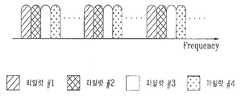
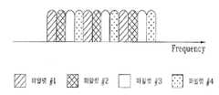
도 3a ~ 도 3d 는 주파수 분할 다중화(Frequency Division Multiplexing)를 이용한 파일럿 전송 방법을 나타낸 일실시예 설명도이다. 도 3 에 도시된 바와 같이, 주파수 분할 다중화 방식은 주어진 시간, 주파수 영역에서 파일럿 신호를 전송하는 UE들을 주파수로 구분하는 방식이다. 즉, 서로 다른 UE 는 서로 다른 부반송파에 파일럿 신호를 전송하도록 하는 것이다.3A to 3D are diagrams illustrating an embodiment of a pilot transmission method using frequency division multiplexing. As shown in FIG. 3, the frequency division multiplexing scheme divides UEs transmitting a pilot signal by frequency in a given time and frequency domain. That is, different UEs are to transmit pilot signals to different subcarriers.
도 3a 는 D-FDMA(distributed FDMA) 방식을 나타낸 일실시예 설명도이다. 한편, 도 3b 는 L-FDMA (localized FDMA) 방식을 나타낸 일실시예 설명도이다. 주파수 축 상에서 파일럿을 전송할 때, 서로 다른 UE들의 신호를 구분하고 UE에게 주파수 대역을 할당하는 방식에는 도 3a 에 나타낸 D-FDMA(distributed FDMA) 방식과 도 3b 에 나타낸 L-FDMA (localized FDMA) 방식이 있다.FIG. 3A is a diagram for explaining an embodiment of a distributed FDMA (D-FDMA) scheme. FIG. 3B is a diagram illustrating an embodiment of a localized FDMA (L-FDMA) scheme. When transmitting a pilot on the frequency axis, a method of distinguishing signals of different UEs and allocating a frequency band to the UE includes a distributed FDMA (D-FDMA) method shown in FIG. 3A and a localized FDMA (L-FDMA) method shown in FIG. 3B. There is this.
도 3a 에 나타낸 바와 같이, D-FDMA 형태의 주파수 분할 다중 파일럿 전송 방식은 하나의 UE 가 보내는 파일럿 신호는 파일럿을 전송하는 주파수 대역에서 일정한 간격으로 분포되게 된다. 전 대역에 걸쳐서 일정한 간격을 두고 하나의 UE 의 CQ 파일럿이 전송되므로, 주파수 스케줄링이 용이해진다.As shown in FIG. 3A, in the D-FDMA type frequency division multiple pilot transmission scheme, pilot signals sent by one UE are distributed at regular intervals in a frequency band for transmitting pilots. Since the CQ pilot of one UE is transmitted at regular intervals over the entire band, frequency scheduling is facilitated.
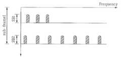
도 3c 및 도 3d 는 주파수 분할 다중화(Frequency Division Multiplexing)에 있어서, 파일럿을 전송하는 UE 의 수에 따른 주파수 간격을 나타낸 일실시예 설명도이다. 도 3c 및 도 3d 에 나타낸 바와 같이, 동시에 파일럿 신호를 전송하는 UE 수가 증가할수록 한 UE 의 파일럿 신호의 주파수 간격은 커지게 된다. 즉, 도 3a 와 같이, 한 번에 파일럿 신호를 전송하는 UE 수가 2 일 때는 각 UE 의 자기 파일럿 신호는 주파수 상에서 2 만큼의 간격으로 위치하게 되지만, 도 3b 에 도시된 바와 같이, 동시에 파일럿 신호를 전송하는 UE 수가 4 일 때에는, 자기 파일럿 신호의 간격은 4 가 된다.3C and 3D are diagrams illustrating an embodiment of frequency intervals according to the number of UEs that transmit pilots in frequency division multiplexing. As shown in FIGS. 3C and 3D, as the number of UEs simultaneously transmitting pilot signals increases, the frequency interval of pilot signals of one UE becomes larger. That is, as shown in FIG. 3A, when the number of UEs transmitting pilot signals at the same time is 2, the self pilot signals of each UE are positioned at intervals of two on the frequency, but as shown in FIG. When the number of UEs to transmit is four, the interval of the self pilot signals is four.
주파수 분할 다중 방식을 이용하여, 보다 많은 UE 를 동시에 지원하기 위해서는 UE 의 자기 파일럿 신호의 간격은 그만큼 넓어지게 된다. 따라서, CQ 파일럿을 동 시간에 전송하는 UE 의 수와 데이터 파일럿을 동시간에 전송하는 UE의 수가 다를 수 있으므로, CQ 파일럿의 주파수 영역에서의 배치 간격과 데이터 파일럿의 배치 간격을 같은 UE 에 대해서도 다르게 설정할 수 있다. 이 때에 일반적으로 동 시간에 상향링크로 데이터를 전송하는 UE의 수보다 CQ 파일럿을 전송하는 UE의 수가 많을 것이므로, CQ 파일럿의 주파수 영역에서의 배치 간격이 데이터 파일럿보다 크게 설정될 수 있다.Using frequency division multiplexing, in order to support more UEs simultaneously, the spacing of the self pilot signals of the UEs becomes wider. Therefore, since the number of UEs transmitting CQ pilots at the same time and the number of UEs transmitting data pilots at the same time may be different, the arrangement intervals in the frequency domain of the CQ pilots and the arrangement intervals of the data pilots are different for the same UE. Can be set. In this case, since the number of UEs transmitting CQ pilots will generally be larger than the number of UEs transmitting data in the uplink at the same time, the allocation interval in the frequency domain of the CQ pilots may be set larger than that of the data pilots.
L-FDMA 형태의 주파수 분할 다중 파일럿 전송 방식은, 도 3(b)에 나타낸 바와 같이, 하나의 UE 가 일정한 구간의 주파수 대역을 할당 받아서 파일럿을 전송하게 된다. 따라서, 이 경우에는 국부적인 일부 대역에 대한 CQ 파일럿 전송만 가능하므로 전체 주파수 대역에 대한 채널 특성을 얻을 수 없다.In the L-FDMA type frequency division multiple pilot transmission scheme, as shown in FIG. Therefore, in this case, only CQ pilot transmission is possible for some local bands, and thus channel characteristics for the entire frequency band cannot be obtained.
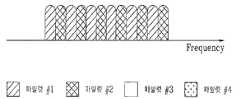
도 4a 및 도 4b 는 코드 분할 다중과 주파수 분할 다중을 결합한 파일럿 신호 전송 방식을 나타낸 일실시예 설명도이다. 파일럿 신호 전송에 있어서, 코드 분할 다중과 주파수 분할 다중을 결합한 방식을 사용하면, 보다 많은 UE 들이 동시에 파일럿 신호를 전송할 수 있게 된다. 일반적으로는, 도 4a 및 도 4b 에 도시한 바와 같이, 전체 전송 대역에서 주파수로 분할된 각각의 주파수 영역에서 코드를 사용함으로써 하나의 분할된 주파수 영역에서 동시에 여러 UE 들이 파일럿을 전송할 수 있게 된다.4A and 4B are exemplary diagrams illustrating a pilot signal transmission method combining code division multiplexing and frequency division multiplexing. In the pilot signal transmission, a combination of code division multiplexing and frequency division multiplexing allows more UEs to transmit pilot signals simultaneously. In general, as shown in FIGS. 4A and 4B, by using a code in each frequency domain divided into frequencies in the entire transmission band, multiple UEs can simultaneously transmit pilots in one divided frequency domain.
도 5a 및 도 5b 는 시간 분할 다중화(Time Division Multiplexing)를 이용한 파일럿 신호 전송 방식을 나타낸 일실시예 설명도이다.5A and 5B are exemplary diagrams illustrating a pilot signal transmission method using time division multiplexing.
일반적인 시분할 다중 방식에 따르면, 도 5a 와 같이 UE 들이 하나의 SB2 에서 시간을 달리하여 CQ 파일럿을 전송한다. 한편, 스케일러블 대역폭(Scalable Bandwidth)을 위해서는 도 5b 와 같은 방식으로 전송할 수 있다. 그러나, 하나의 서브 프레임 내에서 여러 UE 들이 시 분할 방식을 사용하여 CQ 파일럿을 전송하면 PAPR 문제가 발생할 수 있다.According to the general time division multiplexing scheme, UEs transmit CQ pilots at different times in one SB2 as shown in FIG. 5A. On the other hand, for scalable bandwidth (Scalable Bandwidth) can be transmitted in the manner shown in Figure 5b. However, if several UEs transmit a CQ pilot using a time division scheme in one subframe, a PAPR problem may occur.
따라서, 서브 프레임의 배수 단위로 UE 들이 CQ 파일럿 전송 시점을 다르게 하는 바람직하다. 이하에서는 이와같은 방법을 서브 프레임 단위의 시분할 방식(sub-frame level TDM)이라고 한다. 이때, 상기 서브 프레임 단위의 시분할 다중 방식과 상기 설명한 코드분할 다중화 방식, 주파수 분할 다중화 방식 및 코드분할과 주파수 분할을 이용한 다중화 방식을 결합하여 적용할 수 있다.Accordingly, it is desirable for UEs to change CQ pilot transmission time points in multiple units of a subframe. Hereinafter, such a method is called a sub-frame level TDM. In this case, the time division multiplexing method of the sub-frame unit, the code division multiplexing method, the frequency division multiplexing method, and the multiplexing method using code division and frequency division may be applied in combination.
CQ 파일럿을 매 서브 프레임마다 전송하는 방식은 채널 특성의 변화를 빠르 게 Node B 에 알려줄 수 있다. 그러나, 서브 프레임길이가 채널 변화에 비해 충분히 작다면, CQ 파일럿을 매 서브 프레임마다 전송하지 않고 CQ 파일럿을 전송하는 주기를 좀더 길게 함으로써, 보다 많은 UE 가 CQ 파일럿을 전송할 수 있도록 할 수 있다.The method of transmitting the CQ pilot every subframe can inform the Node B of the change in channel characteristics quickly. However, if the subframe length is sufficiently small compared to the channel change, a longer period of transmitting the CQ pilot without transmitting the CQ pilot every subframe may allow more UEs to transmit the CQ pilot.
서브 프레임 단위의 시분할 방식은 파일럿을 전송할 수 있는 UE 의 수를 더 늘리기 위한 방식으로, 각 UE가 매 서브 프레임마다 파일럿 신호를 전송하지 않고 정해진 주기를 가지고, 주기마다 한 번씩 파일럿 신호를 전송한다. 즉, 모든 UE 는 Node B 로부터 CQ 파일럿 신호를 전송하기 시작하는 시간의 오프셋과 몇 개의 서브 프레임 마다 파일럿 신호를 전송할 것인가를 나타내는 전송 주기에 대한 정보를 시그널링으로 받게 된다.The time division method in units of subframes is a method for further increasing the number of UEs capable of transmitting pilots, and each UE transmits a pilot signal once every period without having to transmit a pilot signal every subframe. That is, all UEs receive signaling information about an offset of a time at which the CQ pilot signal starts to be transmitted from the Node B and a transmission period indicating how many subframes to transmit the pilot signal.
도 6a 및 도 6b 는 서브 프레임 단위의 시분할 방식을 나타낸 일실시예 설명도이다. 도 6a 는 CQ 파일럿이 SB2 에 전송되는 경우를 나타낸 일례이다. 도 6a 의 일례와 같이, 모든 UE 의 전송 주기가 2 서브 프레임이고, 일부 UE 들은 전송 오프셋이 0 서브 프레임이고, 또 다른 UE 들은 1 서브 프레임일때, 하나의 셀 또는 섹터 안에 있는 UE 들은 짝수 번째 서브 프레임에 CQ 파일럿을 전송하는 UE 들과, 홀수 번째 서브 프레임에 CQ 파일럿을 전송하는 UE 들로 구분된다.6A and 6B are exemplary diagrams illustrating a time division method in subframe units. 6A shows an example of a case where a CQ pilot is transmitted to SB2. As in the example of FIG. 6A, when all UEs have a transmission period of 2 subframes, some UEs have a transmission offset of 0 subframes, and other UEs have 1 subframe, UEs in one cell or sector are even subframes. UEs transmitting CQ pilots in a frame and UEs transmitting CQ pilots in odd-numbered subframes.
특정 서브 프레임에서 파일럿을 전송하는 UE 들은 주파수 분할 다중 방식이나 코드 분할 다중 방식 혹은 이들의 결합된 형태로 그 서브 프레임에서 직교 채널을 형성하여 파일럿 신호를 전송해야 한다. 이때, 전송 서브 프레임에서 실제로 특정 UE 에게 할당되는 자원은 전송 서브 프레임 시간에 따라 결정된다. 즉, 한 서브 프레임 내에서 주파수 분할 방식으로 UE 들의 파일럿 신호가 다중화되는 경우, 각 UE 들이 자신의 전송 타이밍에 사용하는 주파수는 전송 시점에 의해 결정된다. 따라서, 한 UE 가 사용할 수 있는 주파수 자원은 매 전송 시점마다 같을 수도 있고, 다를 수도 있다. 전송 시점마다 주파수 자원을 다르게 할 경우, 주파수 전 대역의 정보를 보다 정확하게 파악할 수 있게 된다.UEs transmitting a pilot in a specific subframe should transmit a pilot signal by forming an orthogonal channel in the subframe in frequency division multiplexing, code division multiplexing, or a combination thereof. At this time, the resources actually allocated to a specific UE in the transmission subframe is determined according to the transmission subframe time. That is, when pilot signals of UEs are multiplexed in a frequency division scheme within one subframe, a frequency used by each UE for its transmission timing is determined by a transmission time point. Therefore, frequency resources that can be used by a UE may be the same or different at every transmission time point. If the frequency resources are different for each transmission time, it is possible to more accurately grasp the information of the entire frequency band.
한편, 코드 분할 방식으로 UE 들의 파일럿 신호가 다중화되는 경우에는, 각 UE들이 사용하는 코드 또는 코드의 위상 오프셋 역시 전송 시점에 따라 결정된다. 이로써 각 UE 들의 코드 위상 오프셋 값이 매 전송 시점마다 같을 수도 있고, 다를 수도 있다. 혹은, 각 UE 들이 사용하는 코드가 매 전송 시점마다 같을 수도 있고, 다를 수도 있다. 한 UE 가 매 전송 시점마다 코드 위상 값이 다른 코드를 사용할 경우, 혹은 서로 다른 코드를 사용할 경우 코드간의 간섭을 랜덤화 할 수 있는 장점을 가지게 된다.Meanwhile, when pilot signals of UEs are multiplexed by a code division scheme, a code or a phase offset of codes used by each UE is also determined according to a transmission time point. As a result, code phase offset values of respective UEs may be the same or different at every transmission time point. Alternatively, codes used by each UE may be the same or different at every transmission time point. If one UE uses a code having a different code phase value at each transmission time or uses a different code, the UE may have an advantage of randomizing interference between codes.
또한, 한정된 UE 전송 전력 및 여러 요인에 의해 하나의 서브 프레임 또는 그에 상응하는 파일럿 전송 시간 동안에 전 대역에 대한 파일럿 신호를 한번에 전송하지 않고 부대역(sub-band)으로 나누어서 파일럿 신호를 전송할 수도 있다. 이 경우, 각 UE 의 CQ 파일럿 신호 전송 오프셋과 전송 주기를 각 부대역(sub-band)별로 독립적으로 UE에게 알려주는 방식을 제안한다. 이 때, 한 UE가 서로 부대역(sub-band)에서 갖는 전송 주기는 동일할 수도 있다.In addition, due to limited UE transmission power and various factors, the pilot signal may be transmitted by being divided into sub-bands without transmitting the pilot signal for the entire band at one time during one subframe or the corresponding pilot transmission time. In this case, a method of informing the UE of the CQ pilot signal transmission offset and the transmission period of each UE independently for each sub-band is proposed. In this case, transmission periods of one UE in the sub-band may be the same.
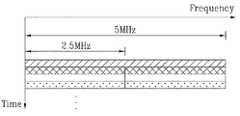
도 6b 는 전체 대역이 10MHz 인 시스템에 있어서, UE 들이 파일럿 신호를 전송할때, 5MHz 부대역(sub-band) 두 개로 나누어서 전송하는 방법을 나타낸 일실시 예 설명도이다. 스케일러블 대역폭(Scalable Bandwidth)을 고려하면, 하나의 셀 내에는, 예를 들어, 5MHz로 전송할 수 있는 UE 와 10MHz 로 전송할 수 있는 UE 들이 공존할 수 있다. 또한, UE 의 전력, 트래픽 양 등에 따라서 하나의 UE 가 10MHz 를 지원할 수 있다 하더라도, 파일럿 신호를 10MHz로 전송하지 않는 경우도 있다. 그림에서 볼 수 있듯이, 파일럿 전송을 서브 프레임서브 프레임 단위로 시분할 하면서, 각 부대역(sub-band)에서 파일럿 신호 전송의 오프셋 및 전송 주기를 달리하게 된다.FIG. 6B is a diagram illustrating a method of transmitting a pilot signal by dividing it into two 5 MHz sub-bands in a system having a total band of 10 MHz. In consideration of scalable bandwidth, for example, a UE capable of transmitting at 5 MHz and UEs capable of transmitting at 10 MHz may coexist in one cell. In addition, even if one UE may support 10 MHz according to the power, traffic amount, etc. of the UE, a pilot signal may not be transmitted at 10 MHz. As shown in the figure, the pilot transmission is time-divided into sub-frame sub-frame units, and the offset and transmission period of the pilot signal transmission are changed in each sub-band.
10MHz UE 의 경우, 자신의 파일럿 신호를 한 서브 프레임 동안 전체 10MHz 에 대해 전송하지 않고, 한 서브 프레임동안에 5MHz 씩 나누어서 전송할 수 있다. 또한, 10MHz UE에게 두 5MHz 대역에 대하여 동일 시간 옵셋(offset)을 부여하여 동일 서브 프레임에서 10 MHz에 해당되는 CQ 파일럿을 전송할 수도 있다. 이러한 방식으로 부대역(sub-band) 별로 독립적으로 각 UE가 CQ 파일럿을 전송하지만, Node B 가 10 MHz 전 대역의 채널 정보를 파악할 수 있게 되므로 각 부대역(sub-band) 단위 (도 6b 의 실시예에서는 5MHz)의 주파수 스케줄링 뿐 아니라, 전 대역(도 6b 의 실시예에서는 10MHz) 에서의 주파수 스케줄링도 가능하다.In case of a 10MHz UE, its own pilot signal may be transmitted by dividing by 5MHz during one subframe without transmitting the entire 10MHz during one subframe. In addition, a 10-MHz UE may transmit a CQ pilot corresponding to 10 MHz in the same subframe by giving an equal time offset to two 5 MHz bands. In this way, each UE transmits a CQ pilot independently for each sub-band, but since Node B can grasp channel information of the entire 10 MHz band, each sub-band unit (see FIG. 6B). In addition to frequency scheduling of 5 MHz in the embodiment, frequency scheduling in the entire band (10 MHz in the embodiment of FIG. 6B) is possible.
한편, 데이터 전송 시 채널 추정을 위한 2 차 파일럿이 기본적으로 전송되어야 하는 경우, 파일럿 신호 전송 방법을 설명하면 다음과 같다. 상기한 바와 같이, 파일럿은 CQ 파일럿과 데이터 파일럿을 포함한다. UE 가 데이터를 전송할 때 보다 정확한 채널 추정을 위하여 파일럿을 추가적으로 더 전송해야 하는 경우가 있다.Meanwhile, when a secondary pilot for channel estimation should be basically transmitted during data transmission, a pilot signal transmission method will be described below. As mentioned above, the pilot includes a CQ pilot and a data pilot. When the UE transmits data, it may be necessary to additionally transmit a pilot for more accurate channel estimation.
즉, SB1 에 데이터 파일럿들만 전송되고, SB2 에는 데이터 파일럿들과 CQ 파 일럿들을 함께 전송하는 방식 및 SB1 에 데이터 파일럿들과 CQ 파일럿들이 함께 전송되고, SB2 에는 데이터 파일럿들만 전송하는 방식에서, 하나의 SB 를 이용해서 데이터 파일럿들만 전송되고, SB2 에서는 데이터 파일럿들과 CQ 파일럿들이 함께 전송되는 방식이 여기에 해당한다.That is, only data pilots are transmitted to SB1, data pilots and CQ pilots are transmitted together to SB2, and data pilots and CQ pilots are transmitted together to SB1, and only data pilots are transmitted to SB2. Only data pilots are transmitted using SB, and data pilots and CQ pilots are transmitted together in SB2.
예를 들어, SB1 에 데이터 파일럿들만 전송되고, SB2 에는 데이터 파일럿들과 CQ 파일럿들을 함께 전송하는 방식에서, SB1 에 전송되는 데이터 파일럿을 1 차 파일럿이라 하고, SB2 에 전송되는 데이터 파일럿을 2차 파일럿이라고 하면, 데이터 전송 UE가 CQ 파일럿을 전송할 경우에, CQ 파일럿이 2차 파일럿으로 대체될 수도 있고, 또는 데이터 전송 UE가 CQ 파일럿을 전송하지 않는 경우 추가로 2차 데이터 파일럿을 전송할 수 있다.For example, in a scheme in which only data pilots are transmitted to SB1 and data pilots and CQ pilots are transmitted to SB2, the data pilot transmitted to SB1 is called a primary pilot and the data pilot transmitted to SB2 is a secondary pilot. In this case, when the data transmitting UE transmits the CQ pilot, the CQ pilot may be replaced by the secondary pilot, or when the data transmitting UE does not transmit the CQ pilot, it may further transmit the secondary data pilot.
한편, 하나의 서브 프레임 내에서 UE 가 데이터와 CQ 파일럿을 전송하는 경우에 파일럿 신호 전송 방법을 설명하면 다음과 같다. 하나의 서브 프레임 내에서 UE 가 데이터도 전송하고 CQ 파일럿도 전송할 경우, 2차 파일럿을 전송하는 방식을 제안한다. 2차 파일럿을 CQ 파일럿과 다중하여 전송하거나, 2차 파일럿을 전송하지 않고 CQ 파일럿을 2 차 파일럿으로 사용할 수 있다.Meanwhile, a pilot signal transmission method when a UE transmits data and a CQ pilot in one subframe is as follows. If a UE transmits data and also transmits a CQ pilot in one subframe, a method of transmitting a secondary pilot is proposed. The secondary pilot may be transmitted in multiplex with the CQ pilot, or the CQ pilot may be used as the secondary pilot without transmitting the secondary pilot.
도 7a 및 도 7b 는 하나의 서브 프레임 내에서 UE 가 데이터 파일럿과 CQ 파일럿을 동시에 전송할 때 2차 파일럿을 전송하는 방법을 나타낸 일실시예 설명도이다. CQ 파일럿을 SB2 에 전송하고, 데이터 파일럿을 SB1 에 전송하는 경우, SB1 에서 파일럿을 전송하는 UE 는 해당 서브 프레임에서 데이터를 전송하는 UE 를 의미한다. UE 0는 해당 서브 프레임에서 데이터를 전송하고, CQ파일럿도 전송한다. 도 7a 은 UE0 는 추가적인 2차 파일럿을 전송하지 않고, CQ 파일럿을 2차 파일럿의 용도로 사용하는 경우의 일례이다. 도 7b 에서 UE0 는 2차 파일럿을 추가 전송한다. 이때, 2차 파일럿은 CQ 파일럿과 다중화되어 전송된다.7A and 7B are exemplary diagrams illustrating a method of transmitting a secondary pilot when a UE simultaneously transmits a data pilot and a CQ pilot in one subframe. When transmitting a CQ pilot to SB2 and transmitting a data pilot to SB1, a UE transmitting a pilot in SB1 means a UE transmitting data in a corresponding subframe.
2차 파일럿이 CQ 파일럿과 하나의 SB 에서 다중화되어 전송되는 경우, 2차 파일럿 전송을 위해, CQ 파일럿 채널 중 하나가 리버스(reserve) 되어 할당된다. 예를 들어, 도 3d 에서 네 개의 CQ 파일럿 채널 1, 2, 3, 4 가 있는데, 이 중의 하나의 채널이 2차 파일럿을 위해 리버스(reserve)되어 CQ 파일럿과 함께 다중화된다. 데이터 파일럿과 CQ 파일럿이 각각의 SB1, SB2 에 모두 전송되어야 하는 경우에도, 데이터 파일럿을 위한 자원이 이와 같은 방식으로 리버스(reserve)될 수 있다.When the secondary pilot is transmitted multiplexed in the CQ pilot and one SB, one of the CQ pilot channels is reversed and allocated for the secondary pilot transmission. For example, there are four
2차 파일럿과 CQ 파일럿이 다중 되는 방식은 앞서 제안했던 시분할, 주파수 분할, 코드 분할, 혹은 이들의 결합에 의한 여러 가지 방식으로 다중화 되어 전송될 수 있다. 2차 파일럿은 1차 파일럿 보다 할당 받는 자원의 양이 더 적다. CQ 파일럿이 SB1, 데이터 파일럿이 SB2 에 전송되거나, CQ 파일럿과 데이터 파일럿 SB1, SB2에 모두 전송될 경우에도 이러한 방법이 적용될 수 있다.The method of multiplexing the secondary pilot and the CQ pilot may be multiplexed and transmitted in various ways by time division, frequency division, code division, or a combination thereof. The secondary pilot has less resources allocated than the primary pilot. This method may also be applied when the CQ pilot is transmitted to SB1 and the data pilot is transmitted to SB2, or both the CQ pilot and the data pilots SB1 and SB2.
도 8 은 데이터 전송 시 채널 추정을 위한 2 차 파일럿이 기본적으로 전송되어야 하고, 시 분할 방식으로 UE가 CQ 파일럿을 전송하는 경우, CQ 파일럿을 전송하지 않는 타이밍에서 데이터를 전송할 때 2차 파일럿 전송 방식을 나타낸 일실시예 설명도이다.FIG. 8 illustrates that a secondary pilot for channel estimation should be basically transmitted during data transmission, and when the UE transmits a CQ pilot in a time division scheme, the second pilot transmission scheme when transmitting data at a timing not transmitting a CQ pilot Illustrates one embodiment shown.
상기한 바와 같이, 서브 프레임 단위의 시분할 다중 방식을 적용하는 경우, UE는 매 서브프레임마다 CQ 파일럿을 전송하지는 않는다. 이때, UE가 CQ 파일럿을 전송하지 않는 서브 프레임에서 데이터를 전송할 경우, 2 차 파일럿의 전송 방식을 설명하면 다음과 같다. 즉, 도 8 에 도시된 바와 같이, UE0 는 서브 프레임 1 과 2 에서 데이터를 전송하고, CQ 파일럿은 서브 프레임1 에서만 전송한다. 도 8 은 CQ 파일럿이 SB2, 데이터 파일럿이 SB1에 전송되는 경우의 일례를 나타낸 것이다. CQ 파일럿을 전송하는 서브 프레임1 에서는 CQ 파일럿을 2차 파일럿으로 사용하고, CQ 파일럿을 전송하지 않는 서브 프레임2 에서 2차 파일럿을 전송하는 방법을 제안한다. 이 때, 2차 파일럿과 CQ 파일럿은 코드분할 다중화, 주파수 분할 다중화, 시간 분할 다중화 및 코드분할과 주파수 분할을 결합한 방식 등으로 다중화되어 전송될 수 있다. 또한, CQ 파일럿이 SB1, 데이터 파일럿이 SB2 에 전송되거나, CQ 파일럿과 데이터 파일럿이 SB1, SB2에 모두 전송될 경우에도 이 방식은 적용될 수 있다.As described above, when time division multiplexing is performed on a subframe basis, the UE does not transmit a CQ pilot every subframe. In this case, when the UE transmits data in a subframe that does not transmit the CQ pilot, the transmission method of the secondary pilot will be described as follows. That is, as shown in FIG. 8, UE0 transmits data in
이상에서 설명한 본 발명은, 본 발명이 속하는 기술분야에서 통상의 지식을 가진 자에 있어 본 발명의 기술적 사상을 벗어나지 않는 범위 내에서 여러 가지 치환, 변형 및 변경이 가능하므로 전술한 실시예 및 첨부된 도면에 의해 한정되는 것이 아니다.The present invention described above is capable of various substitutions, modifications, and changes without departing from the spirit of the present invention for those skilled in the art to which the present invention pertains. It is not limited by the drawings.
본 발명은 많은 UE 들이 CQ 파일럿을 전송할 수 있도록 함으로써, 정확한 채널 추정을 가능하게 하여 통신 효율을 높일 수 있는 효과가 있다.According to the present invention, many UEs can transmit a CQ pilot, thereby enabling accurate channel estimation to increase communication efficiency.
Claims (17)
Translated fromKoreanPriority Applications (11)
| Application Number | Priority Date | Filing Date | Title |
|---|---|---|---|
| CN201310308752.XACN103812628B (en) | 2006-02-07 | 2007-02-07 | Method for transmitting pilot for multiple carrier system |
| EP07708806AEP1982490B1 (en) | 2006-02-07 | 2007-02-07 | Method for transmitting pilot for multiple carrier system |
| JP2008549434AJP5039713B2 (en) | 2006-02-07 | 2007-02-07 | Pilot signal transmission method applied to multi-carrier system |
| TW096104521ATWI430605B (en) | 2006-02-07 | 2007-02-07 | Method and user equipment for transmitting pilot for multiple carrier system |
| PCT/KR2007/000656WO2007091833A2 (en) | 2006-02-07 | 2007-02-07 | Method for transmitting pilot for multiple carrier system |
| ES07708806TES2397406T3 (en) | 2006-02-07 | 2007-02-07 | Pilot transmission procedure for multi-carrier system |
| CN2007800047951ACN101379790B (en) | 2006-02-07 | 2007-02-07 | Method for transmitting a pilot for a multi-carrier system |
| US12/278,564US9203569B2 (en) | 2006-02-07 | 2007-02-07 | Method for transmitting pilot for multiple carrier system |
| US12/509,307US7855947B2 (en) | 2006-02-07 | 2009-07-24 | Method for transmitting pilot for multiple carrier system |
| US14/930,044US9705651B2 (en) | 2006-02-07 | 2015-11-02 | Method for transmitting pilot for multiple carrier system |
| US15/634,048US10270571B2 (en) | 2006-02-07 | 2017-06-27 | Method for transmitting pilot for multiple carrier system |
Applications Claiming Priority (4)
| Application Number | Priority Date | Filing Date | Title |
|---|---|---|---|
| US77122606P | 2006-02-07 | 2006-02-07 | |
| US60/771,226 | 2006-02-07 | ||
| US78367506P | 2006-03-16 | 2006-03-16 | |
| US60/783,675 | 2006-03-16 |
Publications (2)
| Publication Number | Publication Date |
|---|---|
| KR20070080538A KR20070080538A (en) | 2007-08-10 |
| KR100913089B1true KR100913089B1 (en) | 2009-08-21 |
Family
ID=38600896
Family Applications (1)
| Application Number | Title | Priority Date | Filing Date |
|---|---|---|---|
| KR1020060047151AActiveKR100913089B1 (en) | 2006-02-07 | 2006-05-25 | Method for Transmitting Pilot for Multiple Carrier System |
Country Status (8)
| Country | Link |
|---|---|
| US (4) | US9203569B2 (en) |
| EP (1) | EP1982490B1 (en) |
| JP (1) | JP5039713B2 (en) |
| KR (1) | KR100913089B1 (en) |
| CN (2) | CN101379790B (en) |
| ES (1) | ES2397406T3 (en) |
| TW (1) | TWI430605B (en) |
| WO (1) | WO2007091833A2 (en) |
Families Citing this family (32)
| Publication number | Priority date | Publication date | Assignee | Title |
|---|---|---|---|---|
| KR100913089B1 (en)* | 2006-02-07 | 2009-08-21 | 엘지전자 주식회사 | Method for Transmitting Pilot for Multiple Carrier System |
| KR101037829B1 (en)* | 2006-04-25 | 2011-05-31 | 닛본 덴끼 가부시끼가이샤 | Pilot signal transmission method and wireless communication device |
| US7701919B2 (en)* | 2006-05-01 | 2010-04-20 | Alcatel-Lucent Usa Inc. | Method of assigning uplink reference signals, and transmitter and receiver thereof |
| JP4932419B2 (en)* | 2006-06-19 | 2012-05-16 | 株式会社エヌ・ティ・ティ・ドコモ | Mobile communication system |
| WO2008023349A2 (en)* | 2006-08-23 | 2008-02-28 | Nokia Corporation | Pilot design for long term evolution uplink multi-input multi-output antenna system |
| US8259773B2 (en)* | 2006-10-31 | 2012-09-04 | Alcatel Lucent | Method and apparatus for multiplexing code division multiple access and single carrier frequency division multiple access transmissions |
| KR101029676B1 (en)* | 2006-12-22 | 2011-04-15 | 후지쯔 가부시끼가이샤 | Wireless communication method, wireless communication system and user terminal |
| US7869532B2 (en)* | 2007-09-04 | 2011-01-11 | Motorola Mobility, Inc. | Cellular communication system and a method of operation therefor |
| CN102685057B (en)* | 2007-09-12 | 2015-06-17 | 夏普株式会社 | Transmission apparatus and method, processor, OFDM transmission apparatus and method, and wireless communication system |
| KR101413800B1 (en)* | 2007-09-21 | 2014-07-01 | 삼성전자주식회사 | Method and apparatus for transmitting and receiving control information in a mobile communication system |
| KR101537315B1 (en)* | 2008-01-16 | 2015-07-16 | 삼성전자주식회사 | Apparatus and method for designing a resource block that accommodates cyclic prefixes of various sizes in a wireless communication system |
| PL3073665T3 (en)* | 2008-06-23 | 2018-10-31 | Sun Patent Trust | Method of arranging reference signals and wireless communication base station apparatus |
| JP5068699B2 (en)* | 2008-06-23 | 2012-11-07 | 株式会社エヌ・ティ・ティ・ドコモ | Base station apparatus and method |
| KR101208189B1 (en) | 2008-07-23 | 2012-12-04 | 엘지전자 주식회사 | Method for transmitting data in multiple antenna system |
| KR101513044B1 (en) | 2008-08-05 | 2015-04-17 | 엘지전자 주식회사 | Wireless access method to reduce PAPR |
| KR101603338B1 (en)* | 2008-08-11 | 2016-03-15 | 엘지전자 주식회사 | Method and apparatus of transmitting information in wireless communication system |
| EP3113382B1 (en) | 2008-11-14 | 2017-08-30 | Lg Electronics Inc. | Method and apparatus for information transmission in wireless communication system |
| KR101243508B1 (en) | 2008-11-14 | 2013-03-20 | 엘지전자 주식회사 | Method and apparatus for signal transmission in wireless communication system |
| US8817769B2 (en) | 2009-01-26 | 2014-08-26 | Qualcomm Incorporated | Power decision pilot for wireless communication |
| WO2011136519A2 (en)* | 2010-04-28 | 2011-11-03 | Lg Electronics Inc. | Method of transmitting and receiving signals in a mobile communication system using a radio frame including multiple types of subframes and apparatus thereof |
| GB2537073B (en)* | 2010-06-04 | 2017-02-15 | Samsung Electronics Co Ltd | Method and apparatus for multiplexing different efficiency modes in digital radio systems |
| CN102006262A (en)* | 2010-12-09 | 2011-04-06 | 重庆邮电大学 | Method for realizing common function subfunction among OFDM (Orthogonal Frequency Division Multiplexing) system submodules |
| WO2014089832A1 (en)* | 2012-12-14 | 2014-06-19 | 华为技术有限公司 | Pilot signal sending method and network-side device |
| US10826663B2 (en) | 2013-03-13 | 2020-11-03 | Huawei Technologies Co., Ltd. | System and method for determining a pilot signal |
| WO2015188381A1 (en)* | 2014-06-13 | 2015-12-17 | 华为技术有限公司 | Modulation method, apparatus, and device for orthogonal frequency division multiplexing optical signal |
| AU2015321409B2 (en)* | 2014-09-22 | 2019-04-04 | Commonwealth Scientific And Industrial Research Organisation | Linear equalization for use in low latency high speed communication systems |
| GB201502193D0 (en)* | 2015-02-10 | 2015-03-25 | Univ Surrey | Obtaining channel state information in a multicarrier wireless communication network |
| CN107404371B (en)* | 2016-05-20 | 2021-02-09 | 华为技术有限公司 | Data processing method, device and system |
| CN107800525B (en) | 2016-09-05 | 2020-10-09 | 华为技术有限公司 | Method, terminal device and network device for transmitting pilot frequency |
| KR102265440B1 (en)* | 2020-04-22 | 2021-06-15 | 국방과학연구소 | Wireless communication apparatus using pilot signal, wireless communication system thereof and method operating thereof |
| US11444733B2 (en) | 2020-07-29 | 2022-09-13 | Qualcomm Incorporated | Pilot signaling supporting digital post-distortion (DPoD) techniques |
| CN115413009A (en)* | 2021-05-28 | 2022-11-29 | 华为技术有限公司 | Power amplifier nonlinear characteristic parameter determination method and related device |
Citations (4)
| Publication number | Priority date | Publication date | Assignee | Title |
|---|---|---|---|---|
| JPH11355242A (en)* | 1998-06-11 | 1999-12-24 | Victor Co Of Japan Ltd | Multicarrier modulator and demodulator |
| KR20040028490A (en)* | 2002-09-30 | 2004-04-03 | 루센트 테크놀러지스 인크 | Method of power allocation and rate control in OFDMA systems |
| KR20050087947A (en)* | 2004-02-27 | 2005-09-01 | 삼성전자주식회사 | Method and apparatus for transmitting channel quality information in orthogonal frequency division multiple communication system |
| US20060018336A1 (en)* | 2004-07-21 | 2006-01-26 | Arak Sutivong | Efficient signaling over access channel |
Family Cites Families (38)
| Publication number | Priority date | Publication date | Assignee | Title |
|---|---|---|---|---|
| JP3166705B2 (en)* | 1998-04-16 | 2001-05-14 | 松下電器産業株式会社 | Wireless device and transmission method |
| JP3286247B2 (en)* | 1998-05-08 | 2002-05-27 | 松下電器産業株式会社 | Wireless communication system |
| FI107487B (en) | 1999-03-08 | 2001-08-15 | Nokia Mobile Phones Ltd | Procedure for encrypting data transmission in a radio system |
| EP1161801B1 (en) | 1999-03-12 | 2008-09-03 | QUALCOMM Incorporated | Methods and apparatus for power allocation on a reverse link power control channel of a communication system |
| US6606341B1 (en) | 1999-03-22 | 2003-08-12 | Golden Bridge Technology, Inc. | Common packet channel with firm handoff |
| JP3522619B2 (en)* | 2000-01-05 | 2004-04-26 | 株式会社エヌ・ティ・ティ・ドコモ | Transmitter in multi-carrier CDMA transmission system |
| KR100325367B1 (en)* | 2000-01-28 | 2002-03-04 | 박태진 | Apparatus for estimating bit error rate in orthogonal frequency division multiplexing communication system and mothod thereof |
| JP2001244878A (en)* | 2000-03-02 | 2001-09-07 | Yrp Mobile Telecommunications Key Tech Res Lab Co Ltd | Cdma mobile communication system |
| JP3588040B2 (en)* | 2000-07-26 | 2004-11-10 | 松下電器産業株式会社 | Communication terminal device and base station device |
| WO2002041530A1 (en)* | 2000-11-16 | 2002-05-23 | Sony Corporation | Information processing apparatus and communication apparatus |
| KR100790131B1 (en) | 2001-08-24 | 2008-01-02 | 삼성전자주식회사 | Signaling method between media access control layer entities in packet communication system |
| JP3727283B2 (en)* | 2001-11-26 | 2005-12-14 | 松下電器産業株式会社 | Wireless transmission device, wireless reception device, and wireless transmission method |
| KR100790114B1 (en) | 2002-03-16 | 2007-12-31 | 삼성전자주식회사 | Adaptive Pilot Carrier Allocation Method and Apparatus in Orthogonal Frequency Division Multiple Access System |
| US8320301B2 (en)* | 2002-10-25 | 2012-11-27 | Qualcomm Incorporated | MIMO WLAN system |
| US7280467B2 (en) | 2003-01-07 | 2007-10-09 | Qualcomm Incorporated | Pilot transmission schemes for wireless multi-carrier communication systems |
| JP3816450B2 (en)* | 2003-02-18 | 2006-08-30 | Kddi株式会社 | Transmitter and receiver |
| KR100922980B1 (en) | 2003-05-02 | 2009-10-22 | 삼성전자주식회사 | Channel Estimation Apparatus and Method in Orthogonal Frequency Division Multiplexing System Using Multiple Antennas |
| US7177297B2 (en) | 2003-05-12 | 2007-02-13 | Qualcomm Incorporated | Fast frequency hopping with a code division multiplexed pilot in an OFDMA system |
| JP4367044B2 (en)* | 2003-07-23 | 2009-11-18 | 日本電気株式会社 | Communication system and transmission power control method |
| JP4546177B2 (en)* | 2003-07-28 | 2010-09-15 | パナソニック株式会社 | Wireless communication apparatus and wireless communication method |
| KR101225171B1 (en)* | 2003-08-12 | 2013-01-22 | 파나소닉 주식회사 | Radio communication apparatus and pilot symbol transmission method |
| KR100575959B1 (en)* | 2003-09-02 | 2006-05-02 | 삼성전자주식회사 | Apparatus and method for pilot transmission and reception in a communication system using a multi-carrier modulation scheme |
| KR100929094B1 (en)* | 2003-09-20 | 2009-11-30 | 삼성전자주식회사 | System and method for dynamic resource allocation in a communication system using orthogonal frequency division multiple access scheme |
| US7515924B2 (en)* | 2003-10-30 | 2009-04-07 | Qualcomm Incorporated | Method and module for operating independently of a remote terminal if an incoming pilot signal is not detected within a time period and enabling a pilot signal transmission |
| JP4314099B2 (en)* | 2003-11-19 | 2009-08-12 | パナソニック株式会社 | OFDM receiver |
| KR100566274B1 (en)* | 2003-11-20 | 2006-03-30 | 삼성전자주식회사 | Apparatus and Method for Subcarrier Allocation in Orthogonal Frequency Division Multiplexing System |
| KR20050075553A (en)* | 2004-01-15 | 2005-07-21 | 삼성전자주식회사 | Uplink pilot construction method for multicarrier code division multiple access system |
| KR100922948B1 (en)* | 2004-03-11 | 2009-10-22 | 삼성전자주식회사 | Pilot-aided channel estimation technique in uplink ofdma system |
| JP4438482B2 (en) | 2004-04-05 | 2010-03-24 | ソニー・エリクソン・モバイルコミュニケーションズ株式会社 | Reception quality estimation method and apparatus |
| US20050249127A1 (en) | 2004-05-10 | 2005-11-10 | Lucent Technologies, Inc. | Method for subcarrier allocation |
| JP4762619B2 (en)* | 2004-07-14 | 2011-08-31 | パナソニック株式会社 | Communication terminal device and wireless communication method |
| US7418046B2 (en)* | 2004-07-22 | 2008-08-26 | Qualcomm Inc. | Pilot transmission and channel estimation for multiple transmitters |
| US20060188336A1 (en)* | 2005-02-23 | 2006-08-24 | Huber Donald G | Adjustable support bracket for concrete reinforcing bars |
| US8730877B2 (en)* | 2005-06-16 | 2014-05-20 | Qualcomm Incorporated | Pilot and data transmission in a quasi-orthogonal single-carrier frequency division multiple access system |
| US7903628B2 (en)* | 2005-08-22 | 2011-03-08 | Qualcomm Incorporated | Configurable pilots in a wireless communication system |
| TR201904500T4 (en)* | 2005-09-27 | 2019-05-21 | Nokia Technologies Oy | Pilot structure for multi-carrier transmissions. |
| KR100913089B1 (en)* | 2006-02-07 | 2009-08-21 | 엘지전자 주식회사 | Method for Transmitting Pilot for Multiple Carrier System |
| US7860150B2 (en)* | 2006-04-24 | 2010-12-28 | Nokia Corporation | Apparatus, method, and computer program product providing improved uplink pilot transmission schemes |
- 2006
- 2006-05-25KRKR1020060047151Apatent/KR100913089B1/enactiveActive
- 2007
- 2007-02-07ESES07708806Tpatent/ES2397406T3/enactiveActive
- 2007-02-07TWTW096104521Apatent/TWI430605B/enactive
- 2007-02-07JPJP2008549434Apatent/JP5039713B2/enactiveActive
- 2007-02-07CNCN2007800047951Apatent/CN101379790B/enactiveActive
- 2007-02-07CNCN201310308752.XApatent/CN103812628B/enactiveActive
- 2007-02-07USUS12/278,564patent/US9203569B2/enactiveActive
- 2007-02-07EPEP07708806Apatent/EP1982490B1/enactiveActive
- 2007-02-07WOPCT/KR2007/000656patent/WO2007091833A2/enactiveApplication Filing
- 2009
- 2009-07-24USUS12/509,307patent/US7855947B2/enactiveActive
- 2015
- 2015-11-02USUS14/930,044patent/US9705651B2/enactiveActive
- 2017
- 2017-06-27USUS15/634,048patent/US10270571B2/enactiveActive
Patent Citations (4)
| Publication number | Priority date | Publication date | Assignee | Title |
|---|---|---|---|---|
| JPH11355242A (en)* | 1998-06-11 | 1999-12-24 | Victor Co Of Japan Ltd | Multicarrier modulator and demodulator |
| KR20040028490A (en)* | 2002-09-30 | 2004-04-03 | 루센트 테크놀러지스 인크 | Method of power allocation and rate control in OFDMA systems |
| KR20050087947A (en)* | 2004-02-27 | 2005-09-01 | 삼성전자주식회사 | Method and apparatus for transmitting channel quality information in orthogonal frequency division multiple communication system |
| US20060018336A1 (en)* | 2004-07-21 | 2006-01-26 | Arak Sutivong | Efficient signaling over access channel |
Also Published As
| Publication number | Publication date |
|---|---|
| CN103812628B (en) | 2017-04-12 |
| CN101379790A (en) | 2009-03-04 |
| US20090052470A1 (en) | 2009-02-26 |
| TWI430605B (en) | 2014-03-11 |
| US20160056937A1 (en) | 2016-02-25 |
| EP1982490A2 (en) | 2008-10-22 |
| JP2009522917A (en) | 2009-06-11 |
| WO2007091833A2 (en) | 2007-08-16 |
| US10270571B2 (en) | 2019-04-23 |
| US20090290653A1 (en) | 2009-11-26 |
| EP1982490B1 (en) | 2012-11-14 |
| US9203569B2 (en) | 2015-12-01 |
| CN103812628A (en) | 2014-05-21 |
| WO2007091833A3 (en) | 2007-12-13 |
| ES2397406T3 (en) | 2013-03-06 |
| CN101379790B (en) | 2013-08-21 |
| KR20070080538A (en) | 2007-08-10 |
| US20170295003A1 (en) | 2017-10-12 |
| EP1982490A4 (en) | 2011-03-02 |
| US9705651B2 (en) | 2017-07-11 |
| US7855947B2 (en) | 2010-12-21 |
| TW200742318A (en) | 2007-11-01 |
| JP5039713B2 (en) | 2012-10-03 |
Similar Documents
| Publication | Publication Date | Title |
|---|---|---|
| KR100913089B1 (en) | Method for Transmitting Pilot for Multiple Carrier System | |
| KR101350623B1 (en) | Method of Transmitting Scheduling Reference Signal | |
| KR100860663B1 (en) | Apparatus and method for allocating resource in orthogonal frequency division multiple access system | |
| JP5203463B2 (en) | Mobile communication system, mobile station apparatus, base station apparatus, mobile station apparatus communication method, and base station apparatus communication method | |
| JP5074007B2 (en) | User terminal apparatus and base station apparatus | |
| US20070183386A1 (en) | Reference Signal Sequences and Multi-User Reference Signal Sequence Allocation | |
| KR100927919B1 (en) | Pilot assignment method | |
| US20080219236A1 (en) | Control signaling resource assignment in wireless communication networks | |
| CN102160443B (en) | Mobile terminal device, base station device, and common channel signal transmission method | |
| KR20080035437A (en) | Control signal transmission method | |
| CN101155399A (en) | Device and method for transmitting control signaling in variable bandwidth system | |
| KR101467570B1 (en) | Method for allocating radio resource in wireless communication system | |
| KR101181780B1 (en) | Method For Allocating Communication Resource Reducing Inter-Cell Interference | |
| KR20080029713A (en) | AC / NAC signal transmission method and signal transmission setting method | |
| CN101518137A (en) | Ofdma communication system and communication method | |
| KR20070023485A (en) | Radio Resource Allocation Method in OPDM / OFFDM System | |
| KR101285379B1 (en) | Sub-carrier mapping method in uplink and Transmitter implementing the same | |
| KR101187074B1 (en) | Method For Allocating Communication Resource, And Method For Transmitting Signal With The Same | |
| KR101233178B1 (en) | Method For Transmitting Pilot Signal In Multi-Carrier Communication System, And Method For Estimating Channel | |
| KR20080030860A (en) | Pilot Sequence Generation and Cell Planning Method in Monocarrier Frequency Division Multiple Access System |
Legal Events
| Date | Code | Title | Description |
|---|---|---|---|
| PA0109 | Patent application | St.27 status event code:A-0-1-A10-A12-nap-PA0109 | |
| PG1501 | Laying open of application | St.27 status event code:A-1-1-Q10-Q12-nap-PG1501 | |
| PN2301 | Change of applicant | St.27 status event code:A-3-3-R10-R13-asn-PN2301 St.27 status event code:A-3-3-R10-R11-asn-PN2301 | |
| A201 | Request for examination | ||
| PA0201 | Request for examination | St.27 status event code:A-1-2-D10-D11-exm-PA0201 | |
| A302 | Request for accelerated examination | ||
| PA0302 | Request for accelerated examination | St.27 status event code:A-1-2-D10-D17-exm-PA0302 St.27 status event code:A-1-2-D10-D16-exm-PA0302 | |
| D13-X000 | Search requested | St.27 status event code:A-1-2-D10-D13-srh-X000 | |
| D14-X000 | Search report completed | St.27 status event code:A-1-2-D10-D14-srh-X000 | |
| E902 | Notification of reason for refusal | ||
| PE0902 | Notice of grounds for rejection | St.27 status event code:A-1-2-D10-D21-exm-PE0902 | |
| R18-X000 | Changes to party contact information recorded | St.27 status event code:A-3-3-R10-R18-oth-X000 | |
| E13-X000 | Pre-grant limitation requested | St.27 status event code:A-2-3-E10-E13-lim-X000 | |
| P11-X000 | Amendment of application requested | St.27 status event code:A-2-2-P10-P11-nap-X000 | |
| P13-X000 | Application amended | St.27 status event code:A-2-2-P10-P13-nap-X000 | |
| E701 | Decision to grant or registration of patent right | ||
| PE0701 | Decision of registration | St.27 status event code:A-1-2-D10-D22-exm-PE0701 | |
| GRNT | Written decision to grant | ||
| PR0701 | Registration of establishment | St.27 status event code:A-2-4-F10-F11-exm-PR0701 | |
| PR1002 | Payment of registration fee | St.27 status event code:A-2-2-U10-U11-oth-PR1002 Fee payment year number:1 | |
| PG1601 | Publication of registration | St.27 status event code:A-4-4-Q10-Q13-nap-PG1601 | |
| R18-X000 | Changes to party contact information recorded | St.27 status event code:A-5-5-R10-R18-oth-X000 | |
| FPAY | Annual fee payment | Payment date:20120727 Year of fee payment:4 | |
| PR1001 | Payment of annual fee | St.27 status event code:A-4-4-U10-U11-oth-PR1001 Fee payment year number:4 | |
| FPAY | Annual fee payment | Payment date:20130724 Year of fee payment:5 | |
| PR1001 | Payment of annual fee | St.27 status event code:A-4-4-U10-U11-oth-PR1001 Fee payment year number:5 | |
| FPAY | Annual fee payment | Payment date:20140724 Year of fee payment:6 | |
| PR1001 | Payment of annual fee | St.27 status event code:A-4-4-U10-U11-oth-PR1001 Fee payment year number:6 | |
| PN2301 | Change of applicant | St.27 status event code:A-5-5-R10-R13-asn-PN2301 St.27 status event code:A-5-5-R10-R11-asn-PN2301 | |
| FPAY | Annual fee payment | Payment date:20150724 Year of fee payment:7 | |
| PR1001 | Payment of annual fee | St.27 status event code:A-4-4-U10-U11-oth-PR1001 Fee payment year number:7 | |
| FPAY | Annual fee payment | Payment date:20160722 Year of fee payment:8 | |
| PR1001 | Payment of annual fee | St.27 status event code:A-4-4-U10-U11-oth-PR1001 Fee payment year number:8 | |
| PR1001 | Payment of annual fee | St.27 status event code:A-4-4-U10-U11-oth-PR1001 Fee payment year number:9 | |
| PR1001 | Payment of annual fee | St.27 status event code:A-4-4-U10-U11-oth-PR1001 Fee payment year number:10 | |
| PR1001 | Payment of annual fee | St.27 status event code:A-4-4-U10-U11-oth-PR1001 Fee payment year number:11 | |
| PN2301 | Change of applicant | St.27 status event code:A-5-5-R10-R13-asn-PN2301 St.27 status event code:A-5-5-R10-R11-asn-PN2301 | |
| PR1001 | Payment of annual fee | St.27 status event code:A-4-4-U10-U11-oth-PR1001 Fee payment year number:12 | |
| PR1001 | Payment of annual fee | St.27 status event code:A-4-4-U10-U11-oth-PR1001 Fee payment year number:13 | |
| PR1001 | Payment of annual fee | St.27 status event code:A-4-4-U10-U11-oth-PR1001 Fee payment year number:14 | |
| P22-X000 | Classification modified | St.27 status event code:A-4-4-P10-P22-nap-X000 | |
| PR1001 | Payment of annual fee | St.27 status event code:A-4-4-U10-U11-oth-PR1001 Fee payment year number:15 | |
| PR1001 | Payment of annual fee | St.27 status event code:A-4-4-U10-U11-oth-PR1001 Fee payment year number:16 | |
| PR1001 | Payment of annual fee | St.27 status event code:A-4-4-U10-U11-oth-PR1001 Fee payment year number:17 |