KR100908892B1 - Bone fracture treatment instrument - Google Patents
Bone fracture treatment instrumentDownload PDFInfo
- Publication number
- KR100908892B1 KR100908892B1KR1020070037192AKR20070037192AKR100908892B1KR 100908892 B1KR100908892 B1KR 100908892B1KR 1020070037192 AKR1020070037192 AKR 1020070037192AKR 20070037192 AKR20070037192 AKR 20070037192AKR 100908892 B1KR100908892 B1KR 100908892B1
- Authority
- KR
- South Korea
- Prior art keywords
- rod
- fastening device
- fracture treatment
- bone fracture
- bone
- Prior art date
- Legal status (The legal status is an assumption and is not a legal conclusion. Google has not performed a legal analysis and makes no representation as to the accuracy of the status listed.)
- Active
Links
Images


Classifications
- A—HUMAN NECESSITIES
- A61—MEDICAL OR VETERINARY SCIENCE; HYGIENE
- A61B—DIAGNOSIS; SURGERY; IDENTIFICATION
- A61B17/00—Surgical instruments, devices or methods
- A61B17/56—Surgical instruments or methods for treatment of bones or joints; Devices specially adapted therefor
- A61B17/58—Surgical instruments or methods for treatment of bones or joints; Devices specially adapted therefor for osteosynthesis, e.g. bone plates, screws or setting implements
- A61B17/68—Internal fixation devices, including fasteners and spinal fixators, even if a part thereof projects from the skin
- A61B17/70—Spinal positioners or stabilisers, e.g. stabilisers comprising fluid filler in an implant
- A61B17/7074—Tools specially adapted for spinal fixation operations other than for bone removal or filler handling
- A61B17/7083—Tools for guidance or insertion of tethers, rod-to-anchor connectors, rod-to-rod connectors, or longitudinal elements
- A61B17/7089—Tools for guidance or insertion of tethers, rod-to-anchor connectors, rod-to-rod connectors, or longitudinal elements wherein insertion is along an arcuate path
- A—HUMAN NECESSITIES
- A61—MEDICAL OR VETERINARY SCIENCE; HYGIENE
- A61B—DIAGNOSIS; SURGERY; IDENTIFICATION
- A61B17/00—Surgical instruments, devices or methods
- A61B17/00234—Surgical instruments, devices or methods for minimally invasive surgery
- A—HUMAN NECESSITIES
- A61—MEDICAL OR VETERINARY SCIENCE; HYGIENE
- A61B—DIAGNOSIS; SURGERY; IDENTIFICATION
- A61B17/00—Surgical instruments, devices or methods
- A61B17/56—Surgical instruments or methods for treatment of bones or joints; Devices specially adapted therefor
- A61B17/58—Surgical instruments or methods for treatment of bones or joints; Devices specially adapted therefor for osteosynthesis, e.g. bone plates, screws or setting implements
- A61B17/68—Internal fixation devices, including fasteners and spinal fixators, even if a part thereof projects from the skin
- A61B17/70—Spinal positioners or stabilisers, e.g. stabilisers comprising fluid filler in an implant
- A61B17/7001—Screws or hooks combined with longitudinal elements which do not contact vertebrae
- A61B17/7035—Screws or hooks, wherein a rod-clamping part and a bone-anchoring part can pivot relative to each other
- A61B17/7038—Screws or hooks, wherein a rod-clamping part and a bone-anchoring part can pivot relative to each other to a different extent in different directions, e.g. within one plane only
- A—HUMAN NECESSITIES
- A61—MEDICAL OR VETERINARY SCIENCE; HYGIENE
- A61B—DIAGNOSIS; SURGERY; IDENTIFICATION
- A61B17/00—Surgical instruments, devices or methods
- A61B17/56—Surgical instruments or methods for treatment of bones or joints; Devices specially adapted therefor
- A61B17/58—Surgical instruments or methods for treatment of bones or joints; Devices specially adapted therefor for osteosynthesis, e.g. bone plates, screws or setting implements
- A61B17/68—Internal fixation devices, including fasteners and spinal fixators, even if a part thereof projects from the skin
- A61B17/70—Spinal positioners or stabilisers, e.g. stabilisers comprising fluid filler in an implant
- A61B17/7074—Tools specially adapted for spinal fixation operations other than for bone removal or filler handling
- A61B17/7083—Tools for guidance or insertion of tethers, rod-to-anchor connectors, rod-to-rod connectors, or longitudinal elements
- A61B17/7086—Rod reducers, i.e. devices providing a mechanical advantage to allow a user to force a rod into or onto an anchor head other than by means of a rod-to-bone anchor locking element; rod removers
- A—HUMAN NECESSITIES
- A61—MEDICAL OR VETERINARY SCIENCE; HYGIENE
- A61B—DIAGNOSIS; SURGERY; IDENTIFICATION
- A61B17/00—Surgical instruments, devices or methods
- A61B17/56—Surgical instruments or methods for treatment of bones or joints; Devices specially adapted therefor
- A61B17/58—Surgical instruments or methods for treatment of bones or joints; Devices specially adapted therefor for osteosynthesis, e.g. bone plates, screws or setting implements
- A61B17/88—Osteosynthesis instruments; Methods or means for implanting or extracting internal or external fixation devices
- A61B17/8872—Instruments for putting said fixation devices against or away from the bone
- A—HUMAN NECESSITIES
- A61—MEDICAL OR VETERINARY SCIENCE; HYGIENE
- A61B—DIAGNOSIS; SURGERY; IDENTIFICATION
- A61B17/00—Surgical instruments, devices or methods
- A61B17/56—Surgical instruments or methods for treatment of bones or joints; Devices specially adapted therefor
- A61B17/58—Surgical instruments or methods for treatment of bones or joints; Devices specially adapted therefor for osteosynthesis, e.g. bone plates, screws or setting implements
- A61B17/88—Osteosynthesis instruments; Methods or means for implanting or extracting internal or external fixation devices
- A61B17/8897—Guide wires or guide pins
- A—HUMAN NECESSITIES
- A61—MEDICAL OR VETERINARY SCIENCE; HYGIENE
- A61B—DIAGNOSIS; SURGERY; IDENTIFICATION
- A61B17/00—Surgical instruments, devices or methods
- A61B17/56—Surgical instruments or methods for treatment of bones or joints; Devices specially adapted therefor
- A61B17/58—Surgical instruments or methods for treatment of bones or joints; Devices specially adapted therefor for osteosynthesis, e.g. bone plates, screws or setting implements
- A61B17/88—Osteosynthesis instruments; Methods or means for implanting or extracting internal or external fixation devices
- A61B17/90—Guides therefor
- A—HUMAN NECESSITIES
- A61—MEDICAL OR VETERINARY SCIENCE; HYGIENE
- A61B—DIAGNOSIS; SURGERY; IDENTIFICATION
- A61B17/00—Surgical instruments, devices or methods
- A61B17/56—Surgical instruments or methods for treatment of bones or joints; Devices specially adapted therefor
- A61B17/58—Surgical instruments or methods for treatment of bones or joints; Devices specially adapted therefor for osteosynthesis, e.g. bone plates, screws or setting implements
- A61B17/68—Internal fixation devices, including fasteners and spinal fixators, even if a part thereof projects from the skin
- A61B2017/681—Alignment, compression, or distraction mechanisms
Landscapes
- Health & Medical Sciences (AREA)
- Orthopedic Medicine & Surgery (AREA)
- Life Sciences & Earth Sciences (AREA)
- Surgery (AREA)
- Neurology (AREA)
- Heart & Thoracic Surgery (AREA)
- Engineering & Computer Science (AREA)
- Biomedical Technology (AREA)
- Nuclear Medicine, Radiotherapy & Molecular Imaging (AREA)
- Medical Informatics (AREA)
- Molecular Biology (AREA)
- Animal Behavior & Ethology (AREA)
- General Health & Medical Sciences (AREA)
- Public Health (AREA)
- Veterinary Medicine (AREA)
- Surgical Instruments (AREA)
Abstract
Translated fromKoreanDescription
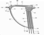
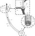
Translated fromKorean도 1은 본 발명의 뼈골절치료용시술장치의 전체를 나타내는 사시도.1 is a perspective view showing the whole of the bone fracture treatment apparatus of the present invention.
도 2는 본 발명의 척추고정장치를 나타내는 사시도.Figure 2 is a perspective view of the spinal column fixing device of the present invention.
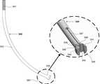
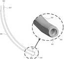
도 3은 본 발명의 교정로드를 나타내는 사시도.3 is a perspective view showing a calibration rod of the present invention.
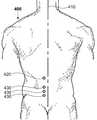
도 4는 본 발명의 뼈골절치료용시술기구가 인체에 통과하는 부위를 나타내는 인체후방도.Figure 4 is a human rear view showing a portion of the bone fracture treatment instrument of the present invention passes through the human body.
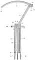
도 5는 본 발명의 뼈골절치료용시술기구를 나타내는 정면순서도.Figure 5 is a front flow diagram showing a surgical bone treatment instrument of the present invention.
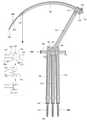
도 6은 본 발명의 뼈골절치료용시술기구의 본체를 중심으로 회전운동을 수행하여 상측으로 이동한 회전부재를 나타내는 정면순서도.Figure 6 is a front flow diagram showing a rotating member moved to the upper side by performing a rotational movement around the body of the bone fracture treatment instrument of the present invention.
도 7은 본 발명의 뼈골절치료용시술기구의 스크류클램퍼하단에 위치한 척추고정장치를 나타내는 정면순서도.Figure 7 is a front flow diagram showing a spinal fixation device located at the lower end of the screw clamper of the treatment instrument for bone fracture treatment of the present invention.
도 8은 본 발명의 뼈골절치료용시술기구의 로드삽입가이드에 걸림체결된 교정로드를 나타내는 정면순서도.Figure 8 is a front flow diagram showing a correction rod fastened to the rod insertion guide of the bone fracture treatment apparatus for treatment of the present invention.
도 9는 본 발명의 뼈골절치료용시술기구의 원터치홀더의 회전에 의한 교정로드의 가압체결을 나타내는 정면순서도.Figure 9 is a front flow chart showing the pressure tightening of the correction rod by the rotation of the one-touch holder of the treatment apparatus for bone fracture treatment of the present invention.
도 10은 본 발명의 뼈골절치료용시술기구의 본체를 중심으로 회전운동을 수행하여 하측으로 이동한 회전부재를 나타내는 정면순서도.Figure 10 is a front flow diagram showing a rotating member moved to the lower side by performing a rotational movement around the body of the bone fracture treatment instrument of the present invention.
도 11은 본 발명의 뼈골절치료용시술기구를 이용하여 환부로의 시술을 재현하여 나타내는 모식도.Figure 11 is a schematic diagram showing by reproducing the procedure to the affected area using the bone fracture treatment apparatus of the present invention.
도 12는 본 발명의 로드체결장치를 나타내는 정면도.12 is a front view showing a rod fastening device of the present invention.
도 13은 본 발명의 로드삽입가이드를 나타내는 정면도.Figure 13 is a front view showing a rod insertion guide of the present invention.
도 14는 본 발명의 로드삽입가이드 내부에 로드체결장치가 위치되어 있는 정면도.Figure 14 is a front view of the rod fastening device is located inside the rod insertion guide of the present invention.
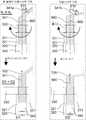
도 15는 본 발명의 원터치홀더를 회전하기 전의 상태를 나타내는 해부정면도.Fig. 15 is an anatomical front view showing a state before rotating a one-touch holder of the present invention.
도 16은 본 발명의 원터치 홀더를 회전하고 난 후의 상태를 나타내는 해부정면도.Fig. 16 is an anatomical front view showing a state after rotating the one-touch holder of the present invention.
도 17은 본 발명의 다중나사부의 다중나사산 대 다중나사골운동의 효과를 나타내는 개념도.17 is a conceptual diagram showing the effect of multi-threaded versus multi-threaded bone movement of the multi-threaded portion of the present invention.
<도면의 주요 부분에 대한 부호의 설명><Explanation of symbols for the main parts of the drawings>
100:척추고정장치100 : spine fixing device
110:스크류 120:헤드부 121:로드삽입구 122:지지부 130:체결나사110: screw 120: head 121: rod insertion opening 122: support 130: tightening screw
200:교정로드200 : calibration rod
210:로드말단 211:그립홈 212:평탄부 220:로드간부 230:로드첨단210: rod end 211: grip groove 212: flat portion 220: rod exec 230: rod tip
300:뼈골절치료용시술기구300 : bone fracture treatment instrument
310:회전부재 311:암결합부310: rotating member 311: female coupling portion
320:로드삽입가이드 321:수결합부 322:로드체결입구320: rod insertion guide 321: male coupling portion 322: rod tightening opening
323:원터치홀더지지부 324:가압경사면323: One-touch holder support 324: Pressure inclined surface
330:원터치홀더 331:다중나사골 332:회전부 333:손잡이 334:고정부330: One-touch holder 331: Multiple threaded bone 332: Rotating portion 333: Handle 334: Fixed part
340:로드체결장치 341:다중나사부340: rod fastening device 341: multi-threaded
341a:다중나사선구조 341b:단일나사선구조341a:
342:굴곡이음부 343:로드체결부 344:그립 345:미끌림삽입부342: bend joint 343: rod fastening portion 344: grip 345: sliding insert
346:로드말단안착부 347:절개부 348:압축경사면 349:그립끝단346: rod end seating portion 347: incision 348: compression slope 349: grip end
350:스크류클램퍼 351:클램퍼홀더 352:홀더핀350: screw clamper 351: clamper holder 352: holder pin
360:본체360: the body
370:조임쇠 371:와셔370: Fastener 371: washer
400:인체후방부위400 : rear part of the human body
410:인체중앙부 420:로드삽입가이드통로 430:스크류클램퍼통로410: central portion 420: rod insertion guide passage 430: screw clamper passage
500:피부600:척추500 : skin600 : spine
610:상위척추체 620:중간척추체 630:하위척추체610: upper spine 620: intermediate spine 630: lower spine
640:디스크 650:스크류이식부위640: disk 650: screw transplantation
700:종축상승운동 710:곡률운동 720:탄성수축운동 730:탄성이완운동700: longitudinal movement 710: curvature movement 720: elastic contraction movement 730: elastic relaxation movement
800:종축선 810:피치각도800: vertical axis 810: pitch angle
900:단일나사부900: single screw
본 발명은 척추고정장치의 시술기구에 관한 것으로, 보다 자세한 설명으로는 정형외과적인 척추병변을 가지고 있는 환자의 개별 척추에 척추고정장치를 이식한 이 후, 상기의 이식된 척추고정장치의 헤드부에 최소침습적으로 교정로드를 삽입하기 위한 뼈골절치료용시술기구에 있어서, 상기의 뼈골절치료용시술기구와 교정로드의 신속하고 간편한 체결방법에 관한 것이다.The present invention relates to a surgical instrument of the spinal fixation device, and more specifically, after implanting the spinal fixation device to the individual spine of a patient having an orthopedic spinal lesion, the head of the implanted spinal fixation device In the bone fracture treatment instrument for minimally invasive correction rod for insertion, relates to a fast and easy fastening method of the bone fracture treatment instrument and the correction rod.
상기의 척추고정장치는 과도한 육체노동으로 인한 척추 이상과, 고령에 따른 퇴행성 척추 이상이 발생한 환자에게 시술하여 척추의 해부학적인 복원 및 안전성을 확보하는 시술장치로서, 보다 자세한 구조의 설명으로는 척추골에 이식되는 스크류, 개별의 척추를 연결하는 교정로드, 상기의 척추고정나사와 결합되는 체결나사를 포함하는 것을 특징으로 한다.The vertebral fixation device is a surgical device to ensure the spinal anatomy and safety of the spine by treating a patient with spinal abnormality caused by excessive physical labor and degenerative vertebral abnormality due to old age. The screw is implanted, orthodontic rod for connecting the individual spine, characterized in that it comprises a fastening screw coupled to the spinal fixing screw.
이하, 종래의 척추고정장치의 시술기구 및 방법을 설명하면 다음과 같다.Hereinafter, a description will be given of the apparatus and method of the conventional spinal fixing device.
종래에는 환자의 척추병변 부위를 의사의 시야를 확보할 만큼 외과적 시술도구를 사용하여 최소한으로 절개한 후 시술이 집도 되었다.Conventionally, the procedure was performed after making a minimal incision using a surgical surgical tool to secure a doctor's field of view of the spinal lesion of the patient.
상기의 일반적인 절개술에 의한 척추고정장치의 이식은 임상의사로 하여금 상당히 숙련된 술기를 요구한다.The implantation of the spinal fixation device by the above general incision requires the clinician to be quite skilled.
상기의 일반적인 절개술에 의한 척추고정장치의 이식은 시술 중 혈액의 과다 배출 및 연부조직의 과다 손상 등의 시술 적 변수에 의해서 일관된 시술의 안전성 확보가 어려운 측면이 있다.The implantation of the spinal fixation device by the general incision is difficult to ensure the safety of the procedure consistent with the surgical parameters such as excessive discharge of blood and excessive damage of soft tissue during the procedure.
근래에는 척추병변을 가지고 있는 환자의 환부에 최소한으로 구멍을 내어 별도의 절개가 필요 없는 간단한 시술이 가능하게 되었다.Recently, minimally invasive lesions in patients with spinal lesions have been made, allowing for simple procedures that do not require a separate incision.
그런데, 상기의 최소한의 구멍 절개만을 하여 시술할 경우, 절개구멍을 통하여 몸속에 척추고정나사를 이식하고, 척추고정나사 헤드부에 교정로드를 체결하는 것은 임상의로 하여금 충분한 시야 확보를 불가능하게 하여, 척추고정장치의 시술에 있어서 매우 정교한 숙련도와 술기를 필요로 한다.However, when performing the procedure with only the minimal hole incision, implanting the spinal fixation screw into the body through the incision hole and fastening the corrective rod to the head of the spinal fixation screw make it impossible for the clinician to secure sufficient vision. However, the procedure of spinal fixation requires very sophisticated skill and skill.
따라서, 근래에 환자의 환부를 최소한으로 절개하면서 시야가 충분히 확보되지 않은 상황에서도 간단하고 용이하게 척추고정장치를 안전하게 시술할 수 있는 척추고정장치의 시술기구와 방법의 필요성이 증대되었다.Therefore, in recent years, the necessity of a surgical device and method of the spinal fixation device which can safely and easily perform the spinal fixation device even in a situation where the vision of the patient is minimally incised while the incision is minimal is increased.
최근에는 시술시에 절개를 최소화하는 것을 중요시하므로, 척추고정장치의 시술시 환자의 등을 최소로 절개한 상태에서 시술하는 기구 및 방법이 제시되고 있다. 이 경우 두 개의 척추 고정나사를 시술할 때에 환자의 등에 3개의 구멍(척추 고정나사 삽입용 2개, 교정로드 삽입용 1개)만 뚫은 후, 교정로드가 일단에 체결되고, 척추고정장치가 통과할 수 있는 관을 구비한 시술기구를 사용함으로써 최소침습시술을 수행하는 방법이 소개되었다.Recently, since it is important to minimize the incision during the procedure, there has been proposed an apparatus and method for performing the procedure in a state in which the back of the patient with a minimum incision during the operation of the spinal fixing device. In this case, when performing two vertebrae fixing screws, only three holes (two for vertebrae fixing screw insertion and one for correcting rod insertion) are drilled on the patient's back, and then the correcting rod is fastened to one end, and the vertebral fixing device passes. A method of performing a minimally invasive procedure was introduced by using a surgical instrument having a tube.
그러나, 상기의 방법에서는 교정로드의 일단을 시술기구에 밀착하여 끼운 상태에서 시술기구와 나사산 대 나사골의 방식으로 체결이 되는 방식이었다. 이러한 방식은 시술기구에 교정로드를 끼운 후에 시술기구의 잠금장치로 결합하게 되기 때문에, 시술기구의 잠금장치의 결합 전에는 교정로드의 일단이 쉽게 빠지고 체결시 간이 긴 단점이 있었다.However, in the above method, the one end of the straightening rod is in close contact with the surgical tool, and the surgical tool and the screw-to-screw bone are fastened. This method is coupled to the locking device of the surgical instrument after the insertion of the calibration rod in the surgical instrument, one end of the calibration rod is easily pulled out before the coupling of the locking mechanism of the surgical instrument has a long time to tighten.
따라서, 최근에는 상기의 문제점을 해결하기 위해서 교정로드의 일단부가 시술기구에 잘 끼워져야 함은 물론, 시술기구로부터 쉽게 이탈되지 않고 간편하게 체결되는 시술기구와 방법의 필요성이 증대되고 있다.Therefore, in recent years, in order to solve the above problems, one end of the calibration rod should be well fitted to the surgical instrument, and the necessity of the surgical instrument and the method to be easily fastened without being easily detached from the surgical instrument is increasing.
따라서, 본 발명은 상기와 같은 종래 기술의 문제점을 해결하기 위하여 고안된 것으로 본 발명의 목적을 다음과 같이 상세히 설명하겠다.Therefore, the present invention is designed to solve the problems of the prior art as described above will be described in detail the object of the present invention.
본 발명의 목적은, 상기와 같은 문제점을 해결하기 위한 것으로서, 상기의 교정로드의 일단부가 시술기구로부터 쉽게 이탈되지 않고 간편하게 체결되는 뼈골절치료용시술기구를 제공하는데 있다.SUMMARY OF THE INVENTION An object of the present invention is to solve the above problems, and to provide an apparatus for treating bone fracture, in which one end of the correction rod is not easily detached from the apparatus.
상기의 목적을 달성하기 위한 본 발명의 실시 예에 따른 척추고정술을 위한 척추고정장치(100)의 뼈골절치료용시술기구(300)는 상기 교정로드(200)를 척추고정장치(100)의 헤드부(120)에 안착시키는 로드삽입가이드(320), 상기 로드삽입가이드(320)의 내부에서 교정로드(200)와 체결되는 로드체결장치(340), 상기 로드체결장치(340)의 다중나사부(341)를 구동시키는 원터치홀더(330)로 구성되는 것을 특징으로 한다.The bone
이하, 첨부된 도면을 참조하여 본 발명의 실시 예를 상세히 설명하겠다.Hereinafter, with reference to the accompanying drawings will be described an embodiment of the present invention;
도 1은 본 발명의 뼈골절치료용시술장치의 전체를 나타내는 사시도이다. 도 1을 참조하면, 상기의 뼈골절치료용시술기구(300)는 상기 교정로드(200)를 척추고정장치(100)의 헤드부(120)에 안착시키는 로드삽입가이드(320), 상기 로드삽입가이드(320) 내부에 위치하며 상기 교정로드(200)와 체결하는 로드체결장치(340), 상기 로드체결장치(340) 상측의 다중나사부(341)와 결합되는 다중나사골(331)을 가지는 원터치홀더(330), 상기 원터치홀더(330)의 외부 이탈을 방지하는 고정부(334), 상기 로드체결장치(340))와 체결되어 상기 척추고정장치(100)의 헤드부(120)에 안착하는 상기 교정로드(200)로 구성되어 상기 뼈골절치료용시술장치와 상기 교정로드간의 체결이 달성되는 것을 특징으로 한다.1 is a perspective view showing the entire bone fracture treatment apparatus of the present invention. Referring to Figure 1, the bone
도 2는 본 발명의 척추고정장치(100)를 나타내는 사시도이다. 도 2를 참조하면, 상기 척추고정장치(100)는 척추로 고정되어지는 스크류(110), 상기 스크류(110) 상측에 교정로드(200)를 체결하는 헤드부(120), 상기 헤드부(120)의 로드삽입구(121)로 관통되는 교정로드(200), 상기 헤드부(120)에 투입된 상기 교정로드(200)를 고정하는 체결나사(130)로 구성을 달성한다.2 is a perspective view showing the spinal
도 3은 본 발명의 교정로드(200)를 나타내는 사시도이다. 도 3을 참조하면, 상기의 교정로드(200)는 원뿔 형태로 돌출된 로드첨단(230), 곡률을 가지는 로드간부(220) 그리고 상기 뼈골절치료용시술기구(300)와 압착체결되는 그립홈(211)을 구비하는 로드말단(210)으로 구성되는 것을 특징으로 한다.3 is a perspective view showing a
도 4는 본 발명의 뼈골절치료용시술기구(300)가 인체에 통과하는 부위를 나타내는 인체후방도이다. 도 4를 참조하면, 상기의 뼈골절치료용시술기구(300)는 상 기 교정로드(200)가 체결된 상기 로드삽입가이드(320)가 통과하기 위한 1개의 로드삽입가이드통로(420)와 상기 척추고정장치(100)를 수용하는 상기 스크류클램퍼(350)가 통과하기 위한 다수개의 스크류클램퍼통로(430)로 삽입되어 국소적인 연부조직의 절개만으로도 시술이 가능한 것을 특징으로 한다.Figure 4 is a rear view of the human body showing the portion of the bone
이하, 도 5에서 도 10은 본 발명의 뼈골절치료용시술기구(300)의 구동을 나타내는 순서도로서 각 과정에서 발생되는 기구의 원리를 상세히 설명하겠다.5 to 10 is a flow chart showing the operation of the bone
도 5는 본 발명의 뼈골절치료용시술기구(300)를 나타내는 정면순서도이다. 도 5를 참조하면, 상기의 뼈골절치료용시술기구(300)에 있어서, 상기 교정로드(200)를 척추고정장치(100)의 헤드부(120)에 안착시키는 상기 로드삽입가이드(320), 상기 로드삽입가이드(320) 내부에 위치하며 상기 교정로드(200)와 체결하는 상기 로드체결장치(340), 상기 로드체결장치(340) 상측의 다중나사부(341)와 결합되는 다중나사골(331)을 가지는 원터치홀더(330), 상기 원터치홀더(330)의 외부이탈을 방지하는 상기 고정부(334)로 구성되는 것을 특징으로 한다.Figure 5 is a front flow diagram showing a bone
도 6은 본 발명의 뼈골절치료용시술기구(300)의 본체(360)를 중심으로 회전운동을 수행하여 상측으로 이동한 회전부재(310)를 나타내는 정면순서도이다. 도 6을 참조하면, 상기의 뼈골절치료용시술기구(300)의 상기 회전부재(310)는 상기 본체(360)를 중심으로 하여 회전운동의 기능을 가지는 것을 특징으로 한다.Figure 6 is a front flow diagram showing a rotating
도 7은 본 발명의 뼈골절치료용시술기구(300)의 스크류클램퍼(350) 하단에 위치한 척추고정장치(100)를 나타내는 정면순서도이다. 도 7을 참조하면, 상기의 척추고정장치(100)는 상기 스크류클램퍼(350)의 내부 통로를 관통하여 척추에 이식 되는 것을 특징으로 한다.Figure 7 is a front flow diagram showing a
도 8은 본 발명의 뼈골절치료용시술기구(300)의 로드삽입가이드(320)에 걸림체결된 교정로드(200)를 나타내는 정면순서도이다. 도 8을 참조하면, 상기의 교정로드(200)는 상기의 로드체결입구(322)에 삽입되어 상기의 로드삽입가이드(320)에 안착되며, 보다 상세한 설명으로는 상기의 교정로드(200)가 상기 로드삽입가이드(320) 내부로 끼워질 때, 상기 로드말단(210)은 상기 로드삽입가이드(320) 내부에 위치하는 상기 로드체결장치(340)의 미끌림삽입부(345)와 접촉하게 된다. 이후 상기 로드체결장치(340)의 절개부(347)를 중심으로 양쪽의 그립(344)이 탄성이완운동(730)으로 벌어지게 되며 상기 그립(344)이 상기 로드말단(210)에 구비된 상기 그립홈(211)을 걸어주게 되어 상기 로드체결장치(340)의 탄성이완운동(730)으로 벌어졌던 상기 그립(344)이 초기위치로 복원되어 상기 걸림체결(또는 1차체결)이 완성이 되는 것을 특징으로 한다.8 is a front flow diagram showing a
또한, 상기의 로드체결장치(340)의 양쪽 그립끝단(349) 사이의 수직거리는 상기 로드말단(210)의 양쪽 평탄부(212) 사이의 수직거리보다 작은 것이 바람직하다.In addition, it is preferable that the vertical distance between both grip ends 349 of the
또한, 상기의 로드삽입가이드(320)에 안착된 상기의 교정로드(200)는 시술자가 강제로 외력을 인가하지 않는 이상 상기의 로드체결장치(340)에서 분리되지 않는 것이 바람직하다.In addition, it is preferable that the
도 9는 본 발명의 뼈골절치료용시술기구의 원터치홀더의 회전에 의한 교정로드의 가압체결을 나타내는 정면순서도이다. 도 9를 참조하면, 상기의 원터치홀 더(330)의 회전에 의해 상기 원터치홀더(330) 내부의 다중나사골(331)과 상기 로드체결장치(340) 상측의 다중나사부(341) 간의 종축상승운동(700)이 발생된다. 상기 종축상승운동(700)의 추진력에 의하여 상기 로드체결장치(340)는 상기 로드삽입가이드(320) 내부의 곡률을 따라 상기 원터치홀더(330) 방향으로 이동하게 된다. 이때 상기 로드체결장치(340)의 압축경사면(348)이 상기 로드삽입가이드(320) 내부의 가압경사면(324)에 눌러져서 상기 로드체결장치(340)의 절개부(347)을 중심으로 상기 그립(344)이 압착되어 상기 로드말단(210)의 그립홈(211)을 견고하게 가압체결(또는 2차체결)하는 것을 특징으로 한다.Figure 9 is a front flow diagram showing the pressure tightening of the orthodontic rod by the rotation of the one-touch holder of the treatment apparatus for bone fracture treatment of the present invention. Referring to FIG. 9, a longitudinal axis upward movement between the
이때, 상기의 원터치홀더(330)의 회전부(332) 하측면은 상기 로드삽입가이드(320) 상측면에 위치하는 원터치홀더지지부(323)를 구름지점으로 하여 상기 로드체결장치(340)의 곡률운동(710)을 유도하는 것을 특징으로 한다.At this time, the lower surface of the
도 10은 본 발명의 뼈골절치료용시술기구(300)의 본체(360)를 중심으로 회전운동을 수행하여 하측으로 이동한 회전부재(310)를 나타내는 정면순서도이다. 도 10을 참조하면, 상기 뼈골절치료용시술기구(300)와 걸림체결 및 가압체결된 상기 교정로드(200)는 본체(360)를 구심점으로 하여 상기 회전부재(310)의 회전운동에 의해 상기 척추고정장치(100)의 헤드부(120)에 구비된 로드삽입구(121)에 안착되는 것을 특징으로 한다.Figure 10 is a front flow diagram showing a rotating
도 11은 본 발명의 뼈골절치료용시술기구(300)를 이용하여 환부로의 시술을 재현하여 나타내는 모식도이다. 도 11을 참조하면, 본 발명의 뼈골절치료용시술기구(300)는 상기 스크류클램퍼(350)와 상기로드삽입가이드(320)가 통과할 피부만 최 소절개하여 효과적으로 척추병변을 시술하는 것을 특징으로 한다.11 is a schematic diagram showing the procedure to the affected area using the bone
도 12는 본 발명의 로드체결장치(340)를 나타내는 정면도이다. 도 12를 참조하면 상기 로드체결장치(340)는 소정의 곡률을 가지는 굴곡이음부(342), 상기 굴곡이음부(342)의 상측으로 다수개의 나사산이 동시에 휘감겨 형성된 상기 다중나사부(341), 상기 굴곡이음부(342)의 하측으로 상기 교정로드(200)의 로드말단(210)을 고정하는 로드체결부(343)를 구비하는 것을 특징으로 한다.12 is a front view showing a
또한, 상기의 로드체결부(343)는 탄성적으로 벌림 및 모음운동을 제공하는 절개부(347), 상기 교정로드(200)의 로드말단(210)에 구비된 상기 그립홈(211)과 체결하기 위해 상기 절개부(347)를 중심축으로 양쪽에 형성된 그립(344)으로 구성되는 것을 특징으로 한다.In addition, the
또한, 상기의 그립(344)은 상기 교정로드(200)의 로드말단(210)의 삽입이 용이하도록 경사진 미끌림삽입부(345)와 상기 미끄림삽입부(345)를 통과하여 위치되는 로드말단안착부(346) 그리고 상기 그립(344)의 외주면에 형성된 압축경사면(348)으로 구성되는 것이 바람직하다.In addition, the
도 13은 본 발명의 로드삽입가이드(320)를 나타내는 정면도이다. 도 13을 참조하면 상기 로드삽입가이드(320)는 상측으로 상기 회전부재(310)의 암결합부(311)와 연결되는 수결합부(321), 하측으로 상기 교정로드(200)가 삽입되는 로드체결입구(322)로 구성되며, 곡률을 가지는 관 형상인 것을 특징으로 한다.13 is a front view showing the
또한, 상기의 로드체결입구(322) 내부로 상기 로드체결장치(340)의 압축경사면(348)에 압축력을 전달하는 가압경사면(324)이 구비되는 것을 특징으로 한다.In addition, a pressure
도 14는 본 발명의 로드삽입가이드(320) 내부에 로드체결장치(340)가 위치되어 있는 정면도이다. 도 14를 참조하면 상기의 로드체결장치(340)는 상기의 로드삽입가이드(320) 내부로 투입되어 구성되는 것을 특징으로 한다.14 is a front view in which the
또한, 상기의 로드체결장치(340)의 압축경사면(348)은 상기의 로드삽입가이드(320)의 가압경사면(324)에 위치되는 것이 바람직하다.In addition, the compression inclined
이하, 도 15에서 도 17에서는 본 발명의 뼈골절치료용시술기구(300)가 상기 교정로드(200)를 체결하는 원리를 상세히 설명하겠다.Hereinafter, in Fig. 15 to 17 will be described in detail the principle of fastening the
도 15와 도 16은 본 발명의 원터치홀더(330)를 회전하기 전/후의 상태를 나타내는 해부정면도이다. 도 15와 도 16을 참조하면 상기 로드체결장치(340)의 다중나사부(341)와 상기 원터치홀더(330) 간의 다중나사산 대 다중나사골 운동은 상기 로드삽입가이드(320)의 원터치홀더지지부(323)를 도약지점으로 하여 상기 다중나사부(341)의 종축상승운동(700)을 유도하는 것을 특징으로 한다.15 and 16 are anatomical front views showing a state before and after rotating the one-
이어서, 종축상승운동(700)을 하는 상기 다중나사부(341)에 의해 상기 로드체결장치(340)의 굴곡이음부(342)는 상기 로드삽입가이드(320) 내부의 곡률을 따라 곡률운동을 수행하는 것을 특징으로 한다.Subsequently, the
이어서, 상기의 굴곡이음부(342)의 곡률운동에 의해 상기 로드체결장치(340)의 압축경사면(348)은 상기 로드삽입가이드(320)의 가압경사면(324)의 내부로 이동함으로써 상기 로드체결장치(340)의 양쪽 그립(344)이 절개부(347)의 범위 내에서 탄성수축운동(720)을 수행하는 것을 특징으로 한다.Subsequently, the compression inclined
또한, 상기의 탄성수축운동(720)을 하는 그립(344)이 상기의 로드말단안착 부(346)에 위치하는 상기 로드말단(210)의 그립홈(211)을 가압체결함으로써, 상기 교정로드(200)가 본 발명의 뼈골절치료용시술기구(300)에 체결되는 것을 특징으로 한다.In addition, the
또한, 상기의 원터치홀더(330)는 반대로 회전할 경우 상기에 기술된 원리에 의해 상기 원터치홀더의 상부면이 고정부를 지지점으로 하여 상기 로드체결장치(340)의 양쪽 그립(344)이 초기의 형상으로 복원되는 것을 특징으로 한다.In addition, when the one-
도 17은 본 발명의 다중나사부(341)의 다중나사산 대 다중나사골운동의 효과를 나타내는 개념도이다. 도 17을 참조하면, 상기의 다중나사부(341)의 외주면에 형성된 나사산은 2개 이상의 나선이 동시에 형성되는 것을 특징으로 한다.17 is a conceptual diagram showing the effect of multi-threaded versus multi-threaded bone movement of the
이는 기하학적으로 동시에 형성되는 나선의 수가 늘어날수록 나사산의 종축선(800)에서 피치각도(810)가 작아지며, 이로 인해 2개 이상의 나선이 동시에 형성된 외주면을 가지는 상기 다중나사부(341)와 1개의 나선이 형성된 외주면을 가지는 단일나사부(900)가 동일한 회전수의 나사산 대 나사골의 운동을 수행했을 때 종축상승운동(700)의 범위는 전자가 더 큰 것이 일반적인 원리이다.As the number of spirals that are simultaneously formed geometrically increases, the
상기의 원리를 바탕으로 도 17의 개념도와 같이 본 발명의 다중나사선구조(341a)와 단일나사선구조(341b)를 비교하자면 상기 원터치홀더(330)를 동일한 각도로 각각 회전시켰을 때 나사산 대 나사골운동으로 유도된 종축상승운동(700)의 범위는 본 발명의 상기 다중나사선구조(341a)를 가지는 다중나사부(341)가 더 크며, 이것이 가지는 효과는 적은 회전에도 상기의 교정로드(200)와 본 발명의 뼈골절치료용시술기구(300)가 빠르고 견고하게 체결됨으로써 시술시간과 상기 체결의 실패를 현저히 줄일 수 있는 장점을 가진다.When comparing the
상술한 바와 같이, 본 발명은 다음과 같은 효과를 달성한다.As described above, the present invention achieves the following effects.
상술한 바와 같이, 본 발명에 따른 상기의 뼈골절치료용시술기구는 국소마취와 최소상처주의의 시술법으로 육체적, 정신적, 시간적, 경제적으로 많은 도움을 주는 우수한 장점이 있다.As described above, the apparatus for treating bone fractures according to the present invention has an excellent advantage of helping physically, mentally, temporally and economically with local anesthesia and minimal wound care.
상술한 바와 같이, 본 발명에 따른 척추고정장치의 뼈골절치료용시술기구는 환자의 피내 연부조직에 거의 영향을 주지 않으며, 시술 시간의 단축과 최소한의 출혈로 시술 중 쇼크 상태 등의 위험을 줄일 수 있고, 시술 후 환자의 통증이 적은 우수한 장점이 있다.As described above, the apparatus for treating bone fracture of the spinal fixation device according to the present invention has little effect on the intradermal soft tissue of the patient, and reduces the risk of shock during the procedure due to shortening of the procedure time and minimal bleeding. It can be, and there is an excellent advantage of less pain of the patient after the procedure.
상술한 바와 같이, 본 발명에 따른 뼈골절치료용시술기구는 척추병변을 가지고 있는 환자를 조기에 치료함으로써 부가적인 합병증 없이 건강한 생활로 돌아갈 수 있고 회복이 빠른 우수한 장점을 가진다.As described above, the apparatus for treating bone fractures according to the present invention has an excellent advantage of being able to return to a healthy life without additional complications and recovering quickly by treating a patient having a spinal lesion early.
상술한 바와 같이, 본 발명에 따른 상기의 뼈골절치료용시술기구는 상기 로드체결장치의 상단에 위치하는 다중나사부와 상기 원터치홀더의 다중나사골 간의 나선운동을 종축상승운동으로 전환하여 상기 로드체결장치 하단부에서 그립의 탄성수축운동으로 전환되어 상기 교정로드 말단의 그립홈을 간편하고 빠르게 압착체결하는 우수한 장점이 있다.As described above, the bone fracture treatment apparatus according to the present invention is the rod fastening device by switching the spiral motion between the multi-screw portion and the multi-screw bone of the one-touch holder located on the top of the rod fastening device to the longitudinal axis movement The lower end portion is converted to the elastic contraction movement of the grip has an excellent advantage of simply and quickly crimping the grip groove of the straightening rod end.
Claims (13)
Translated fromKoreanPriority Applications (1)
| Application Number | Priority Date | Filing Date | Title |
|---|---|---|---|
| KR1020070037192AKR100908892B1 (en) | 2007-04-17 | 2007-04-17 | Bone fracture treatment instrument |
Applications Claiming Priority (1)
| Application Number | Priority Date | Filing Date | Title |
|---|---|---|---|
| KR1020070037192AKR100908892B1 (en) | 2007-04-17 | 2007-04-17 | Bone fracture treatment instrument |
Publications (2)
| Publication Number | Publication Date |
|---|---|
| KR20080093474A KR20080093474A (en) | 2008-10-22 |
| KR100908892B1true KR100908892B1 (en) | 2009-07-23 |
Family
ID=40153967
Family Applications (1)
| Application Number | Title | Priority Date | Filing Date |
|---|---|---|---|
| KR1020070037192AActiveKR100908892B1 (en) | 2007-04-17 | 2007-04-17 | Bone fracture treatment instrument |
Country Status (1)
| Country | Link |
|---|---|
| KR (1) | KR100908892B1 (en) |
Cited By (3)
| Publication number | Priority date | Publication date | Assignee | Title |
|---|---|---|---|---|
| KR101001539B1 (en) | 2010-06-14 | 2010-12-17 | 주식회사 디오메디칼 | Chiropractic rod insertion device and chiropractic device |
| KR101042395B1 (en) | 2010-08-26 | 2011-06-17 | 주식회사 지에스메디칼 | Rod, Keeper, and Spine Minimally Invasive Surgery System |
| KR101253663B1 (en)* | 2012-10-23 | 2013-04-15 | 주식회사 디오메디칼 | Rod holder for minimal invasive surgery |
Families Citing this family (1)
| Publication number | Priority date | Publication date | Assignee | Title |
|---|---|---|---|---|
| KR101067787B1 (en)* | 2009-09-17 | 2011-09-28 | 박근호 | Spinal screw and its treatment device |
Citations (4)
| Publication number | Priority date | Publication date | Assignee | Title |
|---|---|---|---|---|
| US6530929B1 (en) | 1999-10-20 | 2003-03-11 | Sdgi Holdings, Inc. | Instruments for stabilization of bony structures |
| WO2006007419A1 (en)* | 2004-06-16 | 2006-01-19 | General Electric Company | Multilayer composites with special visual effects |
| KR20060008598A (en)* | 2004-07-21 | 2006-01-27 | 주식회사 솔고 바이오메디칼 | Spinal Screws |
| KR20060055640A (en)* | 2004-11-18 | 2006-05-24 | 주식회사 솔고 바이오메디칼 | Spinal screw fixing device using minimally invasive method |
- 2007
- 2007-04-17KRKR1020070037192Apatent/KR100908892B1/enactiveActive
Patent Citations (4)
| Publication number | Priority date | Publication date | Assignee | Title |
|---|---|---|---|---|
| US6530929B1 (en) | 1999-10-20 | 2003-03-11 | Sdgi Holdings, Inc. | Instruments for stabilization of bony structures |
| WO2006007419A1 (en)* | 2004-06-16 | 2006-01-19 | General Electric Company | Multilayer composites with special visual effects |
| KR20060008598A (en)* | 2004-07-21 | 2006-01-27 | 주식회사 솔고 바이오메디칼 | Spinal Screws |
| KR20060055640A (en)* | 2004-11-18 | 2006-05-24 | 주식회사 솔고 바이오메디칼 | Spinal screw fixing device using minimally invasive method |
Cited By (4)
| Publication number | Priority date | Publication date | Assignee | Title |
|---|---|---|---|---|
| KR101001539B1 (en) | 2010-06-14 | 2010-12-17 | 주식회사 디오메디칼 | Chiropractic rod insertion device and chiropractic device |
| WO2011158986A1 (en)* | 2010-06-14 | 2011-12-22 | 주식회사 디오메디칼 | Tool for inserting a rod for spinal correction and a spine-correcting surgical device equipped with the same |
| KR101042395B1 (en) | 2010-08-26 | 2011-06-17 | 주식회사 지에스메디칼 | Rod, Keeper, and Spine Minimally Invasive Surgery System |
| KR101253663B1 (en)* | 2012-10-23 | 2013-04-15 | 주식회사 디오메디칼 | Rod holder for minimal invasive surgery |
Also Published As
| Publication number | Publication date |
|---|---|
| KR20080093474A (en) | 2008-10-22 |
Similar Documents
| Publication | Publication Date | Title |
|---|---|---|
| US9168033B2 (en) | Interspinous implants and methods for implanting same | |
| US8075593B2 (en) | Interspinous implants and methods for implanting same | |
| US8956393B2 (en) | Devices, systems, and methods for acetabulum repair | |
| KR101987004B1 (en) | Bone repair system, kit and method | |
| EP2355732B1 (en) | Reduction tool for spinal rod | |
| US9271763B2 (en) | Transverse rod connector | |
| JP6732789B2 (en) | Method for lamina implant and spinal cord decompression | |
| KR101546924B1 (en) | Pelvic cable solution | |
| US11779355B2 (en) | System for connecting a connecting device, in particular a distractor, to a bone | |
| CA2581882A1 (en) | Connector transfer tool for internal structure stabilization systems | |
| CA2684927C (en) | Interspinous implants and methods for implanting same | |
| US11259845B2 (en) | Bone anchor apparatus and method of use thereof | |
| WO2009083276A1 (en) | Percutaneous interspinous process spacer | |
| JP7137736B2 (en) | articulating rod insert | |
| JP2014050722A (en) | Fixation device for distal tibia flat plate | |
| JP2007525274A (en) | Orthopedic implant rod reduction instrument set and method | |
| JP2008539029A (en) | Percutaneous spinal fixation system | |
| JP2017505701A (en) | Bone fixation system, use thereof, and surgical kit comprising the same | |
| KR100811563B1 (en) | Minimally Invasive Procedure of Spinal Fixation | |
| KR100908892B1 (en) | Bone fracture treatment instrument | |
| KR20100095044A (en) | A apparatus of spinal surgical operation for minimally invasive surgery | |
| CN120189210A (en) | A new closed reduction device for femoral shaft fracture based on the lever principle | |
| KR20210026056A (en) | Drill guide for medical plate |
Legal Events
| Date | Code | Title | Description |
|---|---|---|---|
| A201 | Request for examination | ||
| PA0109 | Patent application | St.27 status event code:A-0-1-A10-A12-nap-PA0109 | |
| PA0201 | Request for examination | St.27 status event code:A-1-2-D10-D11-exm-PA0201 | |
| D13-X000 | Search requested | St.27 status event code:A-1-2-D10-D13-srh-X000 | |
| D14-X000 | Search report completed | St.27 status event code:A-1-2-D10-D14-srh-X000 | |
| E902 | Notification of reason for refusal | ||
| PE0902 | Notice of grounds for rejection | St.27 status event code:A-1-2-D10-D21-exm-PE0902 | |
| P11-X000 | Amendment of application requested | St.27 status event code:A-2-2-P10-P11-nap-X000 | |
| P13-X000 | Application amended | St.27 status event code:A-2-2-P10-P13-nap-X000 | |
| E90F | Notification of reason for final refusal | ||
| PE0902 | Notice of grounds for rejection | St.27 status event code:A-1-2-D10-D21-exm-PE0902 | |
| PG1501 | Laying open of application | St.27 status event code:A-1-1-Q10-Q12-nap-PG1501 | |
| P11-X000 | Amendment of application requested | St.27 status event code:A-2-2-P10-P11-nap-X000 | |
| P13-X000 | Application amended | St.27 status event code:A-2-2-P10-P13-nap-X000 | |
| E90F | Notification of reason for final refusal | ||
| PE0902 | Notice of grounds for rejection | St.27 status event code:A-1-2-D10-D21-exm-PE0902 | |
| R17-X000 | Change to representative recorded | St.27 status event code:A-3-3-R10-R17-oth-X000 | |
| T11-X000 | Administrative time limit extension requested | St.27 status event code:U-3-3-T10-T11-oth-X000 | |
| E13-X000 | Pre-grant limitation requested | St.27 status event code:A-2-3-E10-E13-lim-X000 | |
| P11-X000 | Amendment of application requested | St.27 status event code:A-2-2-P10-P11-nap-X000 | |
| P13-X000 | Application amended | St.27 status event code:A-2-2-P10-P13-nap-X000 | |
| E701 | Decision to grant or registration of patent right | ||
| PE0701 | Decision of registration | St.27 status event code:A-1-2-D10-D22-exm-PE0701 | |
| GRNT | Written decision to grant | ||
| PR0701 | Registration of establishment | St.27 status event code:A-2-4-F10-F11-exm-PR0701 | |
| PR1002 | Payment of registration fee | St.27 status event code:A-2-2-U10-U11-oth-PR1002 Fee payment year number:1 | |
| PG1601 | Publication of registration | St.27 status event code:A-4-4-Q10-Q13-nap-PG1601 | |
| PR1001 | Payment of annual fee | St.27 status event code:A-4-4-U10-U11-oth-PR1001 Fee payment year number:4 | |
| FPAY | Annual fee payment | Payment date:20130701 Year of fee payment:5 | |
| PR1001 | Payment of annual fee | St.27 status event code:A-4-4-U10-U11-oth-PR1001 Fee payment year number:5 | |
| FPAY | Annual fee payment | Payment date:20140702 Year of fee payment:6 | |
| PR1001 | Payment of annual fee | St.27 status event code:A-4-4-U10-U11-oth-PR1001 Fee payment year number:6 | |
| R18-X000 | Changes to party contact information recorded | St.27 status event code:A-5-5-R10-R18-oth-X000 | |
| FPAY | Annual fee payment | Payment date:20150702 Year of fee payment:7 | |
| PR1001 | Payment of annual fee | St.27 status event code:A-4-4-U10-U11-oth-PR1001 Fee payment year number:7 | |
| FPAY | Annual fee payment | Payment date:20160630 Year of fee payment:8 | |
| PR1001 | Payment of annual fee | St.27 status event code:A-4-4-U10-U11-oth-PR1001 Fee payment year number:8 | |
| P22-X000 | Classification modified | St.27 status event code:A-4-4-P10-P22-nap-X000 | |
| PR1001 | Payment of annual fee | St.27 status event code:A-4-4-U10-U11-oth-PR1001 Fee payment year number:9 | |
| PR1001 | Payment of annual fee | St.27 status event code:A-4-4-U10-U11-oth-PR1001 Fee payment year number:10 | |
| FPAY | Annual fee payment | Payment date:20190702 Year of fee payment:11 | |
| PR1001 | Payment of annual fee | St.27 status event code:A-4-4-U10-U11-oth-PR1001 Fee payment year number:11 | |
| PR1001 | Payment of annual fee | St.27 status event code:A-4-4-U10-U11-oth-PR1001 Fee payment year number:12 | |
| PR1001 | Payment of annual fee | St.27 status event code:A-4-4-U10-U11-oth-PR1001 Fee payment year number:13 | |
| PR1001 | Payment of annual fee | St.27 status event code:A-4-4-U10-U11-oth-PR1001 Fee payment year number:14 | |
| PR1001 | Payment of annual fee | St.27 status event code:A-4-4-U10-U11-oth-PR1001 Fee payment year number:15 | |
| PR1001 | Payment of annual fee | St.27 status event code:A-4-4-U10-U11-oth-PR1001 Fee payment year number:16 | |
| PN2301 | Change of applicant | St.27 status event code:A-5-5-R10-R13-asn-PN2301 St.27 status event code:A-5-5-R10-R11-asn-PN2301 | |
| PR1001 | Payment of annual fee | St.27 status event code:A-4-4-U10-U11-oth-PR1001 Fee payment year number:17 | |
| PN2301 | Change of applicant | St.27 status event code:A-5-5-R10-R13-asn-PN2301 St.27 status event code:A-5-5-R10-R11-asn-PN2301 |