KR100908720B1 - Membrane-electrode assembly for fuel cell, and fuel cell system comprising same - Google Patents
Membrane-electrode assembly for fuel cell, and fuel cell system comprising sameDownload PDFInfo
- Publication number
- KR100908720B1 KR100908720B1KR1020070093636AKR20070093636AKR100908720B1KR 100908720 B1KR100908720 B1KR 100908720B1KR 1020070093636 AKR1020070093636 AKR 1020070093636AKR 20070093636 AKR20070093636 AKR 20070093636AKR 100908720 B1KR100908720 B1KR 100908720B1
- Authority
- KR
- South Korea
- Prior art keywords
- catalyst layer
- pore
- fuel cell
- forming member
- membrane
- Prior art date
- Legal status (The legal status is an assumption and is not a legal conclusion. Google has not performed a legal analysis and makes no representation as to the accuracy of the status listed.)
- Expired - Fee Related
Links
Images


Classifications
- H—ELECTRICITY
- H01—ELECTRIC ELEMENTS
- H01M—PROCESSES OR MEANS, e.g. BATTERIES, FOR THE DIRECT CONVERSION OF CHEMICAL ENERGY INTO ELECTRICAL ENERGY
- H01M4/00—Electrodes
- H01M4/86—Inert electrodes with catalytic activity, e.g. for fuel cells
- H—ELECTRICITY
- H01—ELECTRIC ELEMENTS
- H01M—PROCESSES OR MEANS, e.g. BATTERIES, FOR THE DIRECT CONVERSION OF CHEMICAL ENERGY INTO ELECTRICAL ENERGY
- H01M8/00—Fuel cells; Manufacture thereof
- H01M8/10—Fuel cells with solid electrolytes
- H01M8/1009—Fuel cells with solid electrolytes with one of the reactants being liquid, solid or liquid-charged
- H—ELECTRICITY
- H01—ELECTRIC ELEMENTS
- H01M—PROCESSES OR MEANS, e.g. BATTERIES, FOR THE DIRECT CONVERSION OF CHEMICAL ENERGY INTO ELECTRICAL ENERGY
- H01M4/00—Electrodes
- H01M4/86—Inert electrodes with catalytic activity, e.g. for fuel cells
- H01M4/8605—Porous electrodes
- H—ELECTRICITY
- H01—ELECTRIC ELEMENTS
- H01M—PROCESSES OR MEANS, e.g. BATTERIES, FOR THE DIRECT CONVERSION OF CHEMICAL ENERGY INTO ELECTRICAL ENERGY
- H01M4/00—Electrodes
- H01M4/86—Inert electrodes with catalytic activity, e.g. for fuel cells
- H01M4/8647—Inert electrodes with catalytic activity, e.g. for fuel cells consisting of more than one material, e.g. consisting of composites
- H01M4/8657—Inert electrodes with catalytic activity, e.g. for fuel cells consisting of more than one material, e.g. consisting of composites layered
- H—ELECTRICITY
- H01—ELECTRIC ELEMENTS
- H01M—PROCESSES OR MEANS, e.g. BATTERIES, FOR THE DIRECT CONVERSION OF CHEMICAL ENERGY INTO ELECTRICAL ENERGY
- H01M8/00—Fuel cells; Manufacture thereof
- H01M8/04—Auxiliary arrangements, e.g. for control of pressure or for circulation of fluids
- H—ELECTRICITY
- H01—ELECTRIC ELEMENTS
- H01M—PROCESSES OR MEANS, e.g. BATTERIES, FOR THE DIRECT CONVERSION OF CHEMICAL ENERGY INTO ELECTRICAL ENERGY
- H01M8/00—Fuel cells; Manufacture thereof
- H01M8/10—Fuel cells with solid electrolytes
- H01M8/1004—Fuel cells with solid electrolytes characterised by membrane-electrode assemblies [MEA]
- B—PERFORMING OPERATIONS; TRANSPORTING
- B82—NANOTECHNOLOGY
- B82Y—SPECIFIC USES OR APPLICATIONS OF NANOSTRUCTURES; MEASUREMENT OR ANALYSIS OF NANOSTRUCTURES; MANUFACTURE OR TREATMENT OF NANOSTRUCTURES
- B82Y30/00—Nanotechnology for materials or surface science, e.g. nanocomposites
- H—ELECTRICITY
- H01—ELECTRIC ELEMENTS
- H01M—PROCESSES OR MEANS, e.g. BATTERIES, FOR THE DIRECT CONVERSION OF CHEMICAL ENERGY INTO ELECTRICAL ENERGY
- H01M8/00—Fuel cells; Manufacture thereof
- H01M8/10—Fuel cells with solid electrolytes
- H01M2008/1095—Fuel cells with polymeric electrolytes
- H—ELECTRICITY
- H01—ELECTRIC ELEMENTS
- H01M—PROCESSES OR MEANS, e.g. BATTERIES, FOR THE DIRECT CONVERSION OF CHEMICAL ENERGY INTO ELECTRICAL ENERGY
- H01M4/00—Electrodes
- H01M4/86—Inert electrodes with catalytic activity, e.g. for fuel cells
- H01M4/8605—Porous electrodes
- H01M4/861—Porous electrodes with a gradient in the porosity
- Y—GENERAL TAGGING OF NEW TECHNOLOGICAL DEVELOPMENTS; GENERAL TAGGING OF CROSS-SECTIONAL TECHNOLOGIES SPANNING OVER SEVERAL SECTIONS OF THE IPC; TECHNICAL SUBJECTS COVERED BY FORMER USPC CROSS-REFERENCE ART COLLECTIONS [XRACs] AND DIGESTS
- Y02—TECHNOLOGIES OR APPLICATIONS FOR MITIGATION OR ADAPTATION AGAINST CLIMATE CHANGE
- Y02E—REDUCTION OF GREENHOUSE GAS [GHG] EMISSIONS, RELATED TO ENERGY GENERATION, TRANSMISSION OR DISTRIBUTION
- Y02E60/00—Enabling technologies; Technologies with a potential or indirect contribution to GHG emissions mitigation
- Y02E60/30—Hydrogen technology
- Y02E60/50—Fuel cells
Landscapes
- Chemical & Material Sciences (AREA)
- Chemical Kinetics & Catalysis (AREA)
- Electrochemistry (AREA)
- General Chemical & Material Sciences (AREA)
- Life Sciences & Earth Sciences (AREA)
- Engineering & Computer Science (AREA)
- Manufacturing & Machinery (AREA)
- Sustainable Development (AREA)
- Sustainable Energy (AREA)
- Composite Materials (AREA)
- Inert Electrodes (AREA)
- Fuel Cell (AREA)
Abstract
Translated fromKoreanDescription
Translated fromKorean본 발명은 연료 전지용 막-전극 어셈블리, 및 이를 포함하는 연료 전지 시스템에 관한 것으로서, 보다 상세하게는 촉매층내 기공을 통한 물질 이동 및 배출을 용이하게 할 수 있어 연료 전지의 성능을 향상시킬 수 있는 막-전극 어셈블리, 및 이를 포함하는 연료 전지 시스템에 관한 것이다.The present invention relates to a membrane-electrode assembly for a fuel cell and a fuel cell system including the membrane-electrode assembly. More particularly, the present invention relates to a membrane-electrode assembly for a fuel cell, Electrode assembly, and a fuel cell system comprising the same.
연료 전지(Fuel cell)는 메탄올, 에탄올, 천연기체와 같은 탄화수소 계열의 물질 내에 함유되어 있는 수소와 산소의 화학 반응 에너지를 직접 전기 에너지로 변환시키는 발전 시스템이다.A fuel cell is a power generation system that directly converts the chemical reaction energy of hydrogen and oxygen contained in a hydrocarbon-based material such as methanol, ethanol, and natural gas into electrical energy.
이러한 연료 전지는 화석 에너지를 대체할 수 있는 청정 에너지원으로서, 단위 전지의 적층에 의한 스택 구성으로 다양한 범위의 출력을 낼 수 있는 장점을 갖고 있으며, 소형 리튬 전지에 비하여 4 내지 10배의 에너지 밀도를 나타내기 때문에 소형 및 이동용 휴대전원으로 주목받고 있다.This fuel cell is a clean energy source that can replace fossil energy. It has the advantage of being able to output a wide range of output by stacking the unit cells by stacking them. The fuel cell has an energy density of 4 to 10 times So that it is attracting attention as a compact and portable portable power source.
연료 전지의 대표적인 예로는 고분자 전해질형 연료 전지(PEMFC: Polymer Electrolyte Membrane Fuel Cell), 직접 산화형 연료 전지(Direct Oxidation Fuel Cell)를 들 수 있다. 상기 직접 산화형 연료 전지에서 연료로 메탄올을 사용하는 경우를 직접 메탄올형 연료 전지(DMFC: Direct Methanol Fuel Cell)라 한다.Representative examples of the fuel cell include a polymer electrolyte membrane fuel cell (PEMFC) and a direct oxidation fuel cell (Fuel Cell). The case where methanol is used as the fuel in the direct oxidation type fuel cell is referred to as a direct methanol fuel cell (DMFC).
연료 전지에서 전기를 발생시키는 원리는 연료가 연료극인 애노드 전극으로 공급되어 애노드 전극의 촉매에 흡착되고, 연료가 산화되어, 수소 이온과 전자를 생성시키고, 이때 발생된 전자는 외부 회로에 따라 산화극인 캐소드 전극에 도달하며, 수소 이온은 고분자 전해질 막을 통과하여 캐소드 전극으로 전달된다. 캐소드 전극으로 산화제가 공급되고, 상기 산화제, 수소 이온 및 전자가 캐소드 전극의 촉매 상에서 반응하여 물을 생성하면서 전기를 발생시키게 된다.The principle of generating electricity in the fuel cell is that the fuel is supplied to the anode electrode as the fuel electrode and adsorbed to the catalyst of the anode electrode and the fuel is oxidized to generate hydrogen ions and electrons, Reaches the cathode electrode, and hydrogen ions pass through the polymer electrolyte membrane and are transferred to the cathode electrode. The oxidant is supplied to the cathode electrode, and the oxidant, the hydrogen ion and the electrons react with each other on the catalyst of the cathode electrode to generate electricity while generating water.
상기 연료 전지를 시스템으로 구성할 경우, 연료 전지 시스템은 전기를 실질적으로 발생시키는 스택을 포함하고, 상기 스택은 막-전극 어셈블리(Membrane-Electrode Assembly: MEA)와 세퍼레이터(Separator)(또는 바이폴라 플레이트(Bipolar Plate)라고도 함)로 이루어진 단위 셀이 수 개 내지 수 십개로 적층된 구조를 가진다. 상기 막-전극 어셈블리는 수소 이온 전도성 고분자를 포함하는 고분자 전해질 막을 사이에 두고 애노드 전극(일명, "연료극" 또는 "산화 전극"이라 한다)과 캐소드 전극(일명 "공기극" 또는 "환원 전극"이라고 한다)이 위치하는 구조를 가진다.When the fuel cell is configured as a system, the fuel cell system includes a stack that substantially generates electricity, and the stack includes a membrane-electrode assembly (MEA) and a separator (or a bipolar plate Bipolar Plate)) are stacked in several to several tens of unit cells. The membrane-electrode assembly is referred to as an anode (also referred to as a "fuel electrode" or an "oxidizing electrode") and a cathode electrode (also referred to as a "cathode" or a "reducing electrode") with a polymer electrolyte membrane containing a proton- ) Are located.
본 발명의 목적은 촉매층내 기공을 통한 물질 이동 및 배출을 용이하게 할 수 있어 연료 전지의 성능을 향상시킬 수 있는 연료 전지용 막-전극 어셈블리를 제공하는 것이다.An object of the present invention is to provide a membrane-electrode assembly for a fuel cell capable of facilitating the movement and discharge of a substance through pores in a catalyst layer to improve the performance of the fuel cell.
본 발명의 다른 목적은 상기 연료 전지용 막-전극 어셈블리를 포함하는 연료 전지 시스템을 제공하는 것이다.Another object of the present invention is to provide a fuel cell system including the membrane-electrode assembly for a fuel cell.
상기 목적을 달성하기 위하여, 본 발명은 서로 대향하여 위치하는 애노드 전극과 캐소드 전극; 및 상기 애노드 전극과 캐소드 전극 사이에 위치하는 고분자 전해질 막을 포함하며, 상기 캐소드 전극은 촉매 입자를 포함하는 제1 촉매층, 및 촉매 입자 및 기공 형성 부재를 포함하는 제2 촉매층을 포함하는 연료 전지용 막-전극 어셈블리를 제공한다.According to an aspect of the present invention, there is provided a plasma display panel comprising: an anode electrode and a cathode electrode facing each other; And a polymer electrolyte membrane disposed between the anode electrode and the cathode electrode, wherein the cathode electrode comprises a first catalyst layer including catalyst particles, and a second catalyst layer including catalyst particles and a pore- Electrode assembly.
상기 제1 촉매층은 상기 고분자 전해질 막과 접하여 위치하고, 상기 제2 촉매층은 제1 촉매층과 접하여 위치한다.The first catalyst layer is located in contact with the polymer electrolyte membrane, and the second catalyst layer is located in contact with the first catalyst layer.
상기 제2 촉매층에 대한 상기 제1 촉매층의 두께비는 0.15 내지 0.5인 것이 바람직하고, 0.2 내지 0.35인 것이 더욱 바람직하다.The thickness ratio of the first catalyst layer to the second catalyst layer is preferably 0.15 to 0.5, more preferably 0.2 to 0.35.
상기 제1 촉매층은 두께가 15 내지 25㎛인 것이 바람직하고, 17 내지 20㎛인 것이 더욱 바람직하다.The first catalyst layer preferably has a thickness of 15 to 25 mu m, more preferably 17 to 20 mu m.
상기 제2 촉매층은 두께가 50 내지 100㎛인 것이 바람직하고, 65 내지 90㎛ 인 것이 더욱 바람직하다.The second catalyst layer preferably has a thickness of 50 to 100 탆, more preferably 65 to 90 탆.
상기 제2 촉매층은 BET법으로 측정한 비표면적이 1.70m2/g 이상인 것이 바람직하고, 1.80 내지 9.00m2/g 인 것이 더욱 바람직하다.The second catalyst layer is preferred that a specific surface area measured by the BET method of not less than 1.70m2 / g, and 1.80 to 9.00m2 / g which is more preferable.
상기 제2 촉매층은 평균 직경이 20 내지 50nm인 제1 기공, 및 평균 직경이 1.4 내지 3.0㎛인 제2 기공을 포함한다.The second catalyst layer includes a first pore having an average diameter of 20 to 50 nm and a second pore having an average diameter of 1.4 to 3.0 m.
상기 제1 기공은 기공도가 0.010 내지 0.060cm3/g인 것이 바람직하고, 상기 제2 기공은 기공도가 0.23 내지 0.29cm3/g인 것이 바람직하다.The first pores preferably have a porosity of 0.010 to 0.060 cm3 / g, and the second pores preferably have a porosity of 0.23 to 0.29 cm3 / g.
상기 기공 형성 부재는 직경이 30 내지 300nm이고, 길이가 1 내지 30㎛인 탄소 구조체인 것이 바람직하고, 상기 기공 형성 부재는 카본 나노 튜브, 카본 나노 파이버, 카본 나노 와이어, 및 이들의 조합으로 이루어진 군에서 선택되는 것이 바람직하다.Preferably, the pore-forming member is a carbon structure having a diameter of 30 to 300 nm and a length of 1 to 30 μm, and the pore-forming member may be a carbon nanotube, a carbon nanofiber, a carbon nanowire, . ≪ / RTI >
상기 기공 형성 부재가 카본 나노 파이버인 경우, 제2 촉매층은 BET법으로 측정한 비표면적이 1.80 내지 4.00m2/g인 것이 바람직하고, 상기 기공 형성 부재가 카본 나노 튜브인 경우, 제2 촉매층은 BET법으로 측정한 비표면적이 4.00 내지 9.00m2/g인 것이 바람직하다.When the pore-forming member is a carbon nanofiber, the second catalyst layer preferably has a specific surface area measured by a BET method of 1.80 to 4.00 m2 / g, and when the pore-forming member is a carbon nanotube, The specific surface area measured by the BET method is preferably 4.00 to 9.00 m2 / g.
상기 기공 형성 부재는 제2 촉매층 전체 중량에 대하여 1 내지 20 중량%로 포함되는 것이 바람직하고, 상기 기공 형성 부재가 탄소 나노 파이버인 경우, 상기 기공 형성 부재는 제2 촉매층 전체 중량에 대하여 1 내지 5 중량%로 포함되는 것이 바람직하고, 상기 기공 형성 부재가 탄소 나노 튜브인 경우, 상기 기공 형성 부재는 제2 촉매층 전체 중량에 대하여 1 내지 10 중량%로 포함되는 것이 바람직하다.Preferably, the pore-forming member is contained in an amount of 1 to 20 wt% based on the total weight of the second catalyst layer. When the pore-forming member is a carbon nanofiber, the pore- If the pore-forming member is a carbon nanotube, the pore-forming member may be included in an amount of 1 to 10 wt% based on the total weight of the second catalyst layer.
본 발명은 또한, 상기 막-전극 어셈블리, 및 상기 막-전극 어셈블리의 양면에 위치하는 세퍼레이터를 포함하며, 연료와 산화제의 전기화학적 반응을 통하여 전기를 생성시키는 적어도 하나의 전기 발생부; 연료를 상기 전기 발생부로 공급하는 연료 공급부; 및 산화제를 상기 전기 발생부로 공급하는 산화제 공급부를 포함하는 연료 전지 시스템을 제공한다.The present invention also provides a fuel cell system comprising at least one electricity generating unit including the membrane-electrode assembly and a separator located on both sides of the membrane-electrode assembly, the electricity generating unit generating electricity through an electrochemical reaction of the fuel and the oxidant; A fuel supply unit for supplying fuel to the electricity generation unit; And an oxidant supplier for supplying the oxidant to the electricity generator.
상기 연료 전지 시스템은 직접 산화형 연료 전지 시스템인 것이 바람직하다.The fuel cell system is preferably a direct oxidation fuel cell system.
본 발명의 막-전극 어셈블리는 캐소드 전극의 촉매층내 기공을 통한 물질 이동 및 배출을 용이하게 할 수 있어, 연료 전지의 출력 밀도가 향상되고, 수명이 연장된다.The membrane-electrode assembly of the present invention can facilitate the transfer and discharge of the material through the pores in the catalyst layer of the cathode electrode, thereby improving the output density of the fuel cell and prolonging its service life.
이하, 본 발명을 보다 상세하게 설명한다.Hereinafter, the present invention will be described in more detail.
본 발명은 서로 대향하여 위치하는 애노드 전극과 캐소드 전극; 및 상기 애노드 전극과 캐소드 전극 사이에 위치하는 고분자 전해질 막을 포함하며, 상기 캐소드 전극은 촉매 입자를 포함하는 제1 촉매층, 및 촉매 입자 및 기공 형성 부재를 포함하는 제2 촉매층을 포함하는 연료 전지용 막-전극 어셈블리를 제공한다.The present invention relates to an organic light emitting display, comprising: an anode electrode and a cathode electrode facing each other; And a polymer electrolyte membrane disposed between the anode electrode and the cathode electrode, wherein the cathode electrode comprises a first catalyst layer including catalyst particles, and a second catalyst layer including catalyst particles and a pore- Electrode assembly.
일반적으로 막-전극 어셈블리의 캐소드 촉매층은 금속 촉매와 바인더를 용매 에 분산시킨 조성물을 전극 기재나 고분자 전해질 막에 도포하여 형성한다. 이러한 촉매층내 존재하는 기공은 연료 또는 산화제를 공급하고 반응 생성물을 배출시켜 전극 촉매의 활성을 증진시키는 역할을 한다.Generally, the cathode catalyst layer of the membrane-electrode assembly is formed by applying a composition in which a metal catalyst and a binder are dispersed in a solvent to an electrode substrate or a polymer electrolyte membrane. The pores present in the catalyst layer serve to increase the activity of the electrode catalyst by supplying a fuel or an oxidizing agent and discharging a reaction product.
그러나 이와 같은 캐소드 촉매층에서의 반응 생성물의 배출 기능이 원활하지 않게 되면, 연료 또는 산화제 등의 반응물의 공급이 어려워지게 되고 이에 따라 연료 전지의 출력 특성이 저하되는 문제점이 있었다.따라서, 연료 전지의 성능을 향상시키기 위해서는 촉매층내 포함된 기공을 최적 상태로 유지하여 물질 이동에 대한 저항을 최소화하는 것이 중요하다.However, if the discharge function of the reaction products in the cathode catalyst layer is not smooth, the supply of the reactants such as the fuel or the oxidizer becomes difficult, and the output characteristics of the fuel cell deteriorate. Therefore, in order to improve the performance of the fuel cell, it is important to keep the pores contained in the catalyst layer in an optimal state to minimize the resistance to the mass transfer.
종래 촉매층내에서의 기공 형성을 위하여 (NH4)2CO3, NH4HCO3, 또는 (NH4)2C2O4 등의 기공 형성제를 사용한다. 이들 기공 형성제는 촉매와 함께 촉매층 형성용 조성물에 혼합되어 사용되며, 이후 50 내지 170℃에서의 열처리 공정에 의해 제거되어 결과 촉매층내 기공을 형성한다.Pore formers such as (NH4 )2 CO3 , NH4 HCO3 , or (NH4 )2 C2 O4 are used for forming pores in the conventional catalyst layer. These pore-forming agents are used in combination with the catalyst in a composition for forming a catalyst layer and then removed by a heat treatment process at 50 to 170 ° C to form pores in the catalyst layer.
그러나 막-전극 어셈블리의 촉매층내 기공 크기를 제어하기 위해서는 기공 형성제를 볼밀(ball mill)등의 분쇄 장비로 분쇄를 한 후 사용하게 되는데, 이때 볼 밀 등의 분쇄로는 기공 형성제의 평균 입자 크기의 제어가 용이하지 않다. 이에 따라 상기 기공 형성제를 사용한 촉매층내 기공 형성 방법은 촉매층내 미세 기공에 대해서는 크기 제어가 어렵다는 문제가 있다. 또한, 사용된 기공 형성제 제거를 위하여 열 처리 공정을 실시하게 되는데, 열처리에 의한 기공 형성제 제거 효율이 낮으며, 그 결과 촉매층내 상기 기공 형성제가 잔류하여 전자 전도성이 저하되는 문제가 있다. 또한 열처리시 온도가 지나치게 높을 경우에는 촉매의 활성을 열화시키는 문제가 있다.However, in order to control the pore size in the catalyst layer of the membrane-electrode assembly, the pore-forming agent is used after being pulverized by a ball mill or the like. In this case, Size control is not easy. Accordingly, there is a problem that it is difficult to control the size of the micro pores in the catalyst layer in the method of forming pores in the catalyst layer using the pore-forming agent. In addition, a heat treatment process is performed to remove the used pore-forming agent. However, the efficiency of removing the pore-forming agent by heat treatment is low. As a result, the pore-forming agent in the catalyst layer remains and the electron conductivity is lowered. In addition, when the temperature is too high during the heat treatment, there is a problem that the activity of the catalyst deteriorates.
이에 대하여 본 발명의 막-전극 어셈블리의 캐소드 전극은 촉매 입자를 포함하는 제1 촉매층, 및 촉매 입자 및 기공 형성 부재를 포함하는 제2 촉매층을 포함한다. 상기 제1 촉매층은 고분자 전해질 막과 접하도록 형성되는 것으로서, 촉매 입자만을 포함하여 촉매 반응을 극대화시켜 준다. 상기 제2 촉매층은 상기 제1 촉매층과 접하도록 형성되는 것으로서, 상기 제1 촉매층에서 생성된 반응물의 배출을 원활하게 하여 줄 뿐만 아니라, 2차적인 촉매 반응이 일어나게 하여 연료 전지의 성능 및 수명을 향상시켜 준다.In contrast, the cathode electrode of the membrane-electrode assembly of the present invention comprises a first catalyst layer comprising catalyst particles and a second catalyst layer comprising catalyst particles and a pore-forming member. The first catalyst layer is formed in contact with the polymer electrolyte membrane, and includes only catalyst particles to maximize the catalytic reaction. The second catalyst layer is formed to be in contact with the first catalyst layer to smooth the discharge of reactants generated in the first catalyst layer and to improve the performance and lifetime of the fuel cell by causing a secondary catalytic reaction I will.
본 발명은 또한, 상기 막-전극 어셈블리, 및 상기 막-전극 어셈블리의 양면에 위치하는 세퍼레이터를 포함하며, 연료와 산화제의 전기화학적 반응을 통하여 전기를 생성시키는 적어도 하나의 전기 발생부; 연료를 상기 전기 발생부로 공급하는 연료 공급부; 및 산화제를 상기 전기 발생부로 공급하는 산화제 공급부를 포함하는 연료 전지 시스템을 제공한다. 상기 연료 전지 시스템은 직접 산화형 연료 전지 시스템인 것이 바람직하다.The present invention also provides a fuel cell system comprising at least one electricity generating unit including the membrane-electrode assembly and a separator located on both sides of the membrane-electrode assembly, the electricity generating unit generating electricity through an electrochemical reaction of the fuel and the oxidant; A fuel supply unit for supplying fuel to the electricity generation unit; And an oxidant supplier for supplying the oxidant to the electricity generator. The fuel cell system is preferably a direct oxidation fuel cell system.
이하, 첨부한 도면을 참조하여 본 발명의 일 구체예에 대하여 본 발명이 속하는 기술 분야에서 통상의 지식을 가진 자가 용이하게 실시할 수 있도록 상세히 설명한다. 그러나 본 발명은 여러 가지 상이한 형태로 구현될 수 있으며 여기에서 설명하는 일 구체예에 한정되지 않는다.Hereinafter, embodiments of the present invention will be described in detail with reference to the accompanying drawings so that those skilled in the art can easily carry out the present invention. The present invention may, however, be embodied in many different forms and should not be construed as limited to the embodiments set forth herein.
도 1은 본 발명의 일 구체예에 따른 막-전극 어셈블리(1)의 단면을 모식적으 로 나타낸 도면이다. 이하, 도 1을 참조하여 본 발명의 일 구체예에 따른 막-전극 어셈블리(1)를 설명한다.1 is a diagram schematically showing a cross section of a membrane-
상기 막-전극 어셈블리(1)는 연료의 산화와 산화제의 환원 반응을 통해 전기를 발생시키는 부분으로, 하나 또는 수 개가 적층되어 스택을 형성한다.The membrane-
상기 캐소드 전극(5)의 촉매층(54)에서는 산화제의 환원 반응이 일어나며, 그 촉매층(54)에는 연료 전지용 캐소드 촉매가 포함된다. 상기 애노드 전극(3)의 촉매층(34)에서는 연료의 산화 반응이 일어나며, 그 촉매층(34)에는 연료 전지용 애노드 촉매가 포함된다. 상기 애노드 촉매와 캐소드 촉매는 동일한 물질을 사용하여도 무방하다.In the
상기 캐소드 전극(54)은 촉매 입자를 포함하는 제1 촉매층(52), 및 촉매 입자 및 기공 형성 부재를 포함하는 제2 촉매층(53)을 포함한다.The
상기 제2 촉매층(53)에 대한 제1 촉매층(52)의 두께비는 0.15 내지 0.5인 것이 바람직하고, 0.2 내지 0.35인 것이 바람직하다. 상기 제2 촉매층(53)에 대한 제1 촉매층(52)의 두께비가 상기 범위 내일 경우, 물질 전달이 원활하게 이루어져 전지 성능이 향상되어 바람직하다.The thickness ratio of the
상기 제1 촉매층(52)은 두께가 15 내지 25㎛인 것이 바람직하고, 17 내지 20㎛인 것이 더욱 바람직하다. 또한, 상기 제2 촉매층(53)은 두께가 50 내지 100㎛인 것이 바람직하고, 65 내지 90㎛인 것이 더욱 바람직하다.The thickness of the
상기 제1 촉매층(52)의 두께 및 제2 촉매층(53)의 두께가 상기 범위 내에 있을 때, 제1 촉매층(52)과 제2 촉매층(53)의 비율이 적절하여 연료 전지의 성능을 최적화할 수 있다.When the thickness of the
상기 제2 촉매층(53)은 BET법으로 측정한 비표면적이 1.70m2/g 이상인 것이 바람직하고, 1.80 내지 9.00m2/g 인 것이 더욱 바람직하다. 상기 제2 촉매층(53)의 BET법으로 측정한 비표면적이 상기 범위 내에 있을 때, 반응 생성물의 배출이 원활하여 바람직하다.The
상기 제2 촉매층은 평균 직경이 20 내지 50nm인 제1 기공, 및 평균 직경이 1.4 내지 3.0㎛인 제2 기공을 포함한다.The second catalyst layer includes a first pore having an average diameter of 20 to 50 nm and a second pore having an average diameter of 1.4 to 3.0 m.
상기 제1 기공은 기공도가 0.010 내지 0.060cm3/g인 것이 바람직하고, 상기 제2 기공은 기공도가 0.23 내지 0.29cm3/g인 것이 더욱 바람직하다.It is preferable that the first pores have a porosity of 0.010 to 0.060 cm3 / g, and the second pores have a porosity of 0.23 to 0.29 cm3 / g.
상기 제1 기공과 제2 기공의 크기와 기공도가 상기 범위 내에 있을 때, 기상의 반응 생성물은 제1 기공을 통해, 액상의 반응 생성물은 제2 기공을 통해 배출되게 됨으로써, 반응물 및 반응 생성물의 전달 및 배출이 용이하다. 그러나 상기 제1 기공과 제2 기공의 평균 직경이 상기 범위를 벗어날 경우 기상의 반응 생성물과 액상의 반응 생성물이 분리되어 전달 및 배출되지 않고, 함께 이동함으로써 물질 전달 효율이 저하될 우려가 있어 바람직하지 않다.When the size and porosity of the first pore and the second pore are within the above range, the gaseous reaction product is discharged through the first pore and the liquid reaction product is discharged through the second pore, It is easy to transfer and discharge. However, when the average diameter of the first pores and the second pores is out of the above range, the gaseous phase reaction product and the liquid phase reaction product are separated from each other and are not transferred and discharged. not.
상기 기공 형성 부재는 직경이 30 내지 300nm이고, 길이가 1 내지 30㎛인 탄소 구조체인 것이 바람직하다. 상기 형상을 갖는 탄소 구조체를 기공 형성 부재로 사용하는 경우, 기공의 크기를 용이하게 제어할 수 있고, 기공 형성 후 상기 기공 형성 부재를 제거하는 추가적인 공정이 필요하지 않아 바람직하다.The pore-forming member is preferably a carbon structure having a diameter of 30 to 300 nm and a length of 1 to 30 탆. When the carbon structure having the above shape is used as the pore-forming member, the pore size can be easily controlled, and an additional process for removing the pore-forming member after the pore formation is not required, which is preferable.
상기 기공 형성 부재는 카본 나노 튜브, 카본 나노 파이버, 카본 나노 와이어, 및 이들의 조합으로 이루어진 군에서 선택되는 것이 바람직하다. 상기 카본 나노 튜브, 카본 나노 파이버, 카본 나노 와이어, 및 이들의 조합으로 이루어진 군에서 선택되는 탄소 구조체를 기공 형성 부재로 사용하는 경우, 기공의 크기를 용이하게 제어할 수 있고, 기공 형성 후 상기 기공 형성 부재를 제거하는 추가적인 공정이 필요하지 않아 바람직하다.The pore-forming member is preferably selected from the group consisting of carbon nanotubes, carbon nanofibers, carbon nanowires, and combinations thereof. When the carbon structure selected from the group consisting of the carbon nanotubes, the carbon nanofibers, the carbon nanowires, and combinations thereof is used as the pore-forming member, the size of the pores can be easily controlled, There is no need for an additional step of removing the forming member.
상기 기공 형성 부재가 카본 나노 파이버인 경우, 제2 촉매층은 BET법으로 측정한 비표면적이 1.80 내지 4.00m2/g로 형성되고, 상기 기공 형성 부재가 카본 나노 튜브인 경우, 제2 촉매층은 BET법으로 측정한 비표면적이 4.00 내지 9.00m2/g로 형성된다.When the pore-forming member is a carbon nanofiber, the second catalyst layer has a specific surface area of 1.80 to 4.00 m2 / g as measured by a BET method, and when the pore-forming member is a carbon nanotube, The specific surface area measured by the method is 4.00 to 9.00 m2 / g.
상기 제2 촉매층(53)의 BET법으로 측정한 비표면적이 상기 범위 내에 있을 때, 반응 생성물의 배출이 원활하여 바람직하다.When the specific surface area of the
상기 기공 형성 부재는 제2 촉매층 전체 중량에 대하여 1 내지 20 중량%로 포함되는 것이 바람직하고, 상기 기공 형성 부재가 탄소 나노 파이버인 경우, 상기 기공 형성 부재는 제2 촉매층 전체 중량에 대하여 1 내지 5 중량%로 포함되는 것이 바람직하고, 상기 기공 형성 부재가 탄소 나노 튜브인 경우, 상기 기공 형성 부재는 제2 촉매층 전체 중량에 대하여 1 내지 10 중량%로 포함되는 것이 바람직하다.Preferably, the pore-forming member is contained in an amount of 1 to 20 wt% based on the total weight of the second catalyst layer. When the pore-forming member is a carbon nanofiber, the pore- If the pore-forming member is a carbon nanotube, the pore-forming member may be included in an amount of 1 to 10 wt% based on the total weight of the second catalyst layer.
상기 기공 형성 부재가 상기 범위 내로 포함되는 경우, 제1 기공과 제2 기공 의 크기와 기공도를 조절하여 물질 전달을 용이하게 할 수 있어 바람직하다.When the pore-forming member is included within the above range, it is preferable to control the size and porosity of the first pore and the second pore to facilitate mass transfer.
상기 애노드 전극(3) 및 캐소드 전극(5)의 전극 기재(31,51)는 반응원 즉 연료와 산화제가 상기 촉매층(34,54)으로 쉽게 접근할 수 있게 하는 역할을 하는데, 상기 전극 기재(31,51)로는 도전성 기재를 사용하며, 그 대표적인 예로 탄소 페이퍼(carbon paper), 탄소 천(carbon cloth), 탄소 펠트(carbon felt) 또는 금속 천(섬유 상태의 금속천으로 구성된 다공성의 필름 또는 고분자 섬유로 형성된 천의 표면에 금속 필름이 형성된 것을 말함)이 사용될 수 있으나, 이에 한정되는 것은 아니다.The
상기 고분자 전해질 막(2)으로는 애노드 전극(3)의 촉매층(34)에서 생성된 수소 이온을 캐소드 전극(5)의 촉매층(54)으로 이동시키는 이온 교환의 기능을 가지며, 수소 이온 전도성이 우수한 고분자를 사용할 수 있다.The
도 2는 본 발명의 일 구체예에 따른 연료 전지 시스템(100)의 개략적인 구조를 나타낸 도면이다. 상기 도 2를 참조하여 본 발명의 일 구체예에 따른 연료 전지 시스템(100)의 개략적인 구조를 설명한다. 또한, 도 2에 나타낸 구조는 연료 및 산화제를 펌프(151,171)를 사용하여 전기 발생부(130)로 공급하는 시스템을 나타내었으나, 본 발명의 연료 전지용 막-전극 어셈블리(131)가 이러한 구조에 한정되어 사용되는 것은 아니며, 펌프를 사용하지 않는 확산 방식을 이용하는 구조의 연료 전지 시스템에도 사용될 수 있음은 당연한 일이다.FIG. 2 is a diagram showing a schematic structure of a
연료 전지 시스템(100)은 연료의 산화 반응과 산화제의 환원 반응을 통해 전기 에너지를 발생시키는 적어도 하나의 전기 발생부(130)를 갖는 스택(110)과, 상 기한 연료를 공급하는 연료 공급부(150)와, 산화제를 전기 발생부(130)로 공급하는 산화제 공급부(170)를 포함하여 구성된다.The
상기 연료를 공급하는 연료 공급부(150)는 연료를 저장하는 연료 탱크(153)와, 연료 탱크(153)에 연결 설치되는 연료 펌프(151)를 구비한다. 상기한 연료 펌프(151)는 소정의 펌핑력에 의해 연료 탱크(153)에 저장된 연료를 배출시키는 기능을 하게 된다.The
상기 스택(110)의 전기 발생부(130)로 산화제를 공급하는 산화제 공급부(170)는 소정의 펌핑력으로 산화제를 흡입하는 적어도 하나의 산화제 펌프(171)를 구비한다.The
상기 전기 발생부(130)는 연료와 산화제를 산화 및 환원 반응시키는 막-전극 어셈블리(131)와 이 막-전극 어셈블리(131)의 양측에 연료와 산화제를 공급하기 위한 세퍼레이터(바이폴라 플레이트)(133,135)로 구성된다.The
이하 본 발명의 바람직한 실시예 및 비교예를 기재한다. 그러나 하기 실시예는 본 발명의 바람직한 일 실시예일뿐 본 발명이 하기한 실시예에 의해 한정되는 것은 아니다.Hereinafter, preferred embodiments and comparative examples of the present invention will be described. However, the following examples are only a preferred embodiment of the present invention, and the present invention is not limited by the following examples.
(연료 전지의 제조)(Production of fuel cell)
(실시예 1)(Example 1)
이소프로필알코올에 Pt 블랙(Hispec 1000®, Johnson Matthey사), 및 10중량% 나피온(Nafion®,Dupont사) 수계 분산액을 첨가한 후 교반하여 촉매층 형성용 조성물을 제조하고, 상기 촉매층 형성용 조성물을 탄소 페이퍼에 스크린 인쇄법으로 코팅한 후 건조하여 캐소드 전극의 제1 촉매층을 18㎛의 두께로 형성하였다. 상기 캐소드 전극의 제1 촉매층은 Pt를 2mg/cm2로 포함하였다.Pt black (Hispec 1000® , Johnson Matthey) and 10% by weight Nafion (R ) were added to isopropyl alcohol, Dupont Co.) aqueous dispersion was added and stirred to prepare a composition for forming a catalyst layer. The composition for forming a catalyst layer was coated on a carbon paper by a screen printing method and then dried to form a first catalyst layer of a cathode electrode Respectively. The first catalyst layer of the cathode electrode contained2 mg / cm2 of Pt.
이소프로필알코올에 Pt 블랙(Hispec 1000®, Johnson Matthey사), 탄소 나노 튜브, 및 10중량% 나피온(Nafion®, Dupont사) 수계 분산액을 첨가한 후 교반하여 촉매층 형성용 조성물을 제조하고, 상기 촉매층 형성용 조성물을 상기 제1 촉매층 위에 스크린 인쇄법으로 코팅한 후 건조하여 캐소드 전극의 제2 촉매층을 82㎛의 두께로 형성하였다. 상기 캐소드 전극의 제2 촉매층은 Pt를 8mg/cm2로 포함하고, 제2 촉매층 전체 중량에 대하여 탄소 나노 튜브를 1 중량%로 포함하였다.A composition for forming a catalyst layer was prepared by adding Pt black (Hispec 1000® , Johnson Matthey Co.), carbon nanotubes, and a 10% by weight Nafion® (DuPont) aqueous dispersion to isopropyl alcohol and stirring the mixture, A composition for forming a catalyst layer was coated on the first catalyst layer by a screen printing method and dried to form a second catalyst layer having a thickness of 82 탆 on the cathode electrode. The second catalyst layer of the cathode electrode contained 8 mg / cm2 of Pt and 1 wt% of carbon nanotubes with respect to the total weight of the second catalyst layer.
이소프로필알코올에 Pt/Ru 블랙 (Hispec 6000®, Johnson Matthey사), 및 10중량% 나피온(Nafion®, Dupont사) 수계 분산액을 첨가한 후 교반하여 촉매층 형성용 조성물을 제조하고, 상기 촉매층 형성용 조성물을 탄소 페이퍼에 스크린 인쇄법으로 코팅한 후 건조하여 애노드 전극을 제조하였다. 상기 애노드 전극은 Pt/Ru를 6mg/cm2로 포함하였다.A composition for forming a catalyst layer was prepared by adding Pt / Ru black (Hispec 6000® , Johnson Matthey) and 10% by weight Nafion® (DuPont) aqueous dispersion to isopropyl alcohol and stirring the mixture to form a catalyst layer Was coated on a carbon paper by a screen printing method and dried to prepare an anode electrode. The anode electrode contained 6 mg / cm <2 > of Pt / Ru.
상업용 Nafion 115막을 각각 90℃의 3% 과산화수소, 0.5M 황산 수용액에서 2시간 처리한 후, 100℃의 탈이온수에서 1시간 동안 세척하여 H+형 Nafion 115막을 고분자 전해질 막으로 하였다. 상기 고분자 전해질 막의 양면에 상기 제조된 캐소 드 전극 및 애노드 전극을 접합하여 막-전극 어셈블리를 제조하였다.Commercial Nafion 115 membranes were treated with 3% hydrogen peroxide and 0.5 M aqueous sulfuric acid solution at 90 ° C for 2 hours and then washed with deionized water at 100 ° C for 1 hour, respectively, to form the H+ -type Nafion 115 membrane as a polymer electrolyte membrane. The prepared cathode electrode and anode electrode were bonded to both sides of the polymer electrolyte membrane to prepare a membrane-electrode assembly.
이후, 상기 막-전극 어셈블리를 두 장의 가스켓(gasket) 사이에 삽입한 후 일정형상의 기체 유로 채널과 냉각 채널이 형성된 2개의 세퍼레이터에 삽입하고 구리 엔드(end) 플레이트 사이에서 압착하여 연료 전지를 제조하였다.Thereafter, the membrane-electrode assembly was inserted between two gaskets, and then inserted into two separators having gas channel channels of a predetermined shape and cooling channels, and pressed between the copper end plates to manufacture a fuel cell. Respectively.
(실시예 2)(Example 2)
상기 캐소드 전극의 제2 촉매층이 제2 촉매층 전체 중량에 대하여 탄소 나노 튜브를 5 중량%로 포함하도록 한 것을 제외하고는 실시예 1과 동일하게 실시하여 연료 전지를 제조하였다.A fuel cell was manufactured in the same manner as in Example 1, except that the second catalyst layer of the cathode electrode contained 5 wt% of carbon nanotubes relative to the total weight of the second catalyst layer.
(실시예 3)(Example 3)
상기 캐소드 전극의 제2 촉매층이 제2 촉매층 전체 중량에 대하여 탄소 나노 튜브를 10 중량%로 포함하도록 한 것을 제외하고는 실시예 1과 동일하게 실시하여 연료 전지를 제조하였다.A fuel cell was fabricated in the same manner as in Example 1, except that the second catalyst layer of the cathode electrode contained 10 wt% of carbon nanotubes relative to the total weight of the second catalyst layer.
(실시예 4)(Example 4)
상기 캐소드 전극의 제2 촉매층이 제2 촉매층 전체 중량에 대하여 탄소 나노 튜브를 15 중량%로 포함하도록 한 것을 제외하고는 실시예 1과 동일하게 실시하여 연료 전지를 제조하였다.A fuel cell was manufactured in the same manner as in Example 1, except that the second catalyst layer of the cathode electrode contained 15 wt% of carbon nanotubes with respect to the total weight of the second catalyst layer.
(실시예 5)(Example 5)
상기 캐소드 전극의 제2 촉매층이 제2 촉매층 전체 중량에 대하여 탄소 나노 튜브를 20 중량%로 포함하도록 한 것을 제외하고는 실시예 1과 동일하게 실시하여 연료 전지를 제조하였다.A fuel cell was manufactured in the same manner as in Example 1, except that the second catalyst layer of the cathode electrode contained 20 wt% of carbon nanotubes with respect to the total weight of the second catalyst layer.
(실시예 6)(Example 6)
캐소드 전극의 제2 촉매층이 탄소 나노 튜브를 대신하여 탄소 나노 파이버(VGCF®, Showa Denko Co, Ltd.)를 제2 촉매층 전체 중량에 대하여 1.5 중량%로 포함하도록 한 것을 제외하고는 실시예 1과 동일하게 실시하여 연료 전지를 제조하였다.Example 1 was repeated except that the second catalyst layer of the cathode electrode contained 1.5 wt% of carbon nanofibers (VGCF® , Showa Denko Co, Ltd.) in place of the carbon nanotubes in the total weight of the second catalyst layer. The same procedure was followed to prepare a fuel cell.
(실시예 7)(Example 7)
상기 캐소드 전극의 제2 촉매층이 제2 촉매층 전체 중량에 대하여 탄소 나노 파이버를 3 중량%로 포함하도록 한 것을 제외하고는 실시예 6와 동일하게 실시하여 연료 전지를 제조하였다.A fuel cell was manufactured in the same manner as in Example 6, except that the second catalyst layer of the cathode electrode contained 3 wt% of carbon nanofibers relative to the total weight of the second catalyst layer.
(실시예 8)(Example 8)
상기 캐소드 전극의 제2 촉매층이 제2 촉매층 전체 중량에 대하여 탄소 나노 파이버를 5 중량%로 포함하도록 한 것을 제외하고는 실시예 6와 동일하게 실시하여 연료 전지를 제조하였다.A fuel cell was manufactured in the same manner as in Example 6, except that the second catalyst layer of the cathode electrode contained 5 wt% of carbon nanofibers relative to the total weight of the second catalyst layer.
(실시예 9)(Example 9)
상기 캐소드 전극의 제2 촉매층이 제2 촉매층 전체 중량에 대하여 탄소 나노 파이버를 10 중량%로 포함하도록 한 것을 제외하고는 실시예 6와 동일하게 실시하여 연료 전지를 제조하였다.A fuel cell was manufactured in the same manner as in Example 6, except that the second catalyst layer of the cathode electrode contained 10 wt% of carbon nanofibers relative to the total weight of the second catalyst layer.
(실시예 10)(Example 10)
상기 캐소드 전극의 제2 촉매층이 제2 촉매층 전체 중량에 대하여 탄소 나노 파이버를 15 중량%로 포함하도록 한 것을 제외하고는 실시예 6와 동일하게 실시하여 연료 전지를 제조하였다.A fuel cell was manufactured in the same manner as in Example 6, except that the second catalyst layer of the cathode electrode contained 15 wt% of carbon nanofibers relative to the total weight of the second catalyst layer.
(실시예 11)(Example 11)
상기 캐소드 전극의 제2 촉매층이 제2 촉매층 전체 중량에 대하여 탄소 나노 파이버를 20 중량%로 포함하도록 한 것을 제외하고는 실시예 6와 동일하게 실시하여 연료 전지를 제조하였다.A fuel cell was manufactured in the same manner as in Example 6, except that the second catalyst layer of the cathode electrode contained 20 wt% of carbon nanofibers relative to the total weight of the second catalyst layer.
(비교예 1)(Comparative Example 1)
상기 캐소드 전극의 제2 촉매층을 형성하지 않고, 제1 촉매층을 100㎛의 두께로 형성한 것을 제외하고는 실시예 1과 동일하게 실시하여 연료 전지를 제조하였다.A fuel cell was manufactured in the same manner as in Example 1, except that the second catalyst layer of the cathode was not formed and the first catalyst layer was formed to a thickness of 100 탆.
(비교예 2)(Comparative Example 2)
상기 캐소드 전극의 제1 촉매층은 형성하지 않고, 제2 촉매층을 100㎛의 두께로 형성한 것을 제외하고는 실시예 1과 동일하게 실시하여 연료 전지를 제조하였다.A fuel cell was manufactured in the same manner as in Example 1, except that the first catalyst layer of the cathode electrode was not formed and the second catalyst layer was formed to a thickness of 100 탆.
(비교예 3)(Comparative Example 3)
상기 캐소드 전극의 제1 촉매층은 형성하지 않고, 제2 촉매층을 100㎛의 두께로 형성한 것을 제외하고는 실시예 2와 동일하게 실시하여 연료 전지를 제조하였다.A fuel cell was manufactured in the same manner as in Example 2 except that the first catalyst layer of the cathode electrode was not formed and the second catalyst layer was formed to a thickness of 100 탆.
(비교예 4)(Comparative Example 4)
상기 캐소드 전극의 제1 촉매층은 형성하지 않고, 제2 촉매층을 100㎛의 두 께로 형성한 것을 제외하고는 실시예 3과 동일하게 실시하여 연료 전지를 제조하였다.A fuel cell was manufactured in the same manner as in Example 3 except that the first catalyst layer of the cathode electrode was not formed and the second catalyst layer was formed to have a thickness of 100 mu m.
(비교예 5)(Comparative Example 5)
상기 캐소드 전극의 제1 촉매층은 형성하지 않고, 제2 촉매층을 100㎛의 두께로 형성한 것을 제외하고는 실시예 5와 동일하게 실시하여 연료 전지를 제조하였다.A fuel cell was fabricated in the same manner as in Example 5 except that the first catalyst layer of the cathode electrode was not formed and the second catalyst layer was formed to a thickness of 100 탆.
(비교예 6)(Comparative Example 6)
상기 캐소드 전극의 제1 촉매층은 형성하지 않고, 제2 촉매층을 100㎛의 두께로 형성한 것을 제외하고는 실시예 6과 동일하게 실시하여 연료 전지를 제조하였다.A fuel cell was fabricated in the same manner as in Example 6, except that the first catalyst layer of the cathode electrode was not formed and the second catalyst layer was formed to a thickness of 100 탆.
(비교예 7)(Comparative Example 7)
상기 캐소드 전극의 제1 촉매층은 형성하지 않고, 제2 촉매층을 100㎛의 두께로 형성한 것을 제외하고는 실시예 7과 동일하게 실시하여 연료 전지를 제조하였다.A fuel cell was manufactured in the same manner as in Example 7 except that the first catalyst layer of the cathode electrode was not formed and the second catalyst layer was formed to a thickness of 100 탆.
(비교예 8)(Comparative Example 8)
상기 캐소드 전극의 제1 촉매층은 형성하지 않고, 제2 촉매층을 100㎛의 두께로 형성한 것을 제외하고는 실시예 8과 동일하게 실시하여 연료 전지를 제조하였다.A fuel cell was manufactured in the same manner as in Example 8 except that the first catalyst layer of the cathode electrode was not formed and the second catalyst layer was formed to a thickness of 100 탆.
(비교예 9)(Comparative Example 9)
상기 캐소드 전극의 제1 촉매층은 형성하지 않고, 제2 촉매층을 100㎛의 두 께로 형성한 것을 제외하고는 실시예 9과 동일하게 실시하여 연료 전지를 제조하였다.A fuel cell was fabricated in the same manner as in Example 9 except that the first catalyst layer of the cathode electrode was not formed and the second catalyst layer was formed to have a thickness of 100 mu m.
(기공 형성 부재의 투과 전자 현미경((Transmission electron microscope of pore forming memberTEMTEM) 관찰)) observe)
실시예 1에서 사용한 탄소 나노 튜브와 실시예 6에서 사용한 탄소 나노 파이버를 투과 전자 현미경으로 관찰하였고, 그 결과를 도 3 및 도 4에 나타내었다.The carbon nanotubes used in Example 1 and the carbon nanofibers used in Example 6 were observed with a transmission electron microscope, and the results are shown in FIG. 3 and FIG.
도 3 및 도 4를 참조하면, 상기 기공 형성 부재로 사용한 탄소 나노 튜브와 탄소 나노 파이버는 각각 직경이 30 내지 300nm이고, 길이가 1 내지 30㎛인 것을 알 수 있다.Referring to FIGS. 3 and 4, the carbon nanotubes and the carbon nanofibers used as the pore-forming member have a diameter of 30 to 300 nm and a length of 1 to 30 μm, respectively.
(제2(Second촉매층의The 주사 전자 현미경( Scanning Electron Microscope (SEMSEM) 관찰)) observe)
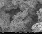
실시예 2, 실시예 6, 및 비교예 1의 캐소드 전극의 제2 촉매층을 주사 전자 현미경으로 관찰하였고, 그 결과를 각각 도 5 내지 7에 나타내었다.The second catalyst layers of the cathode electrodes of Example 2, Example 6, and Comparative Example 1 were observed with a scanning electron microscope, and the results are shown in FIGS. 5 to 7, respectively.
도 5 내지 7을 참조하면, 실시예 1 및 실시예 6의 제2 촉매층은 비교예 1의 제2 촉매층에 비하여 비표면적이 향상되었음을 알 수 있다.Referring to FIGS. 5 to 7, it can be seen that the specific surface area of the second catalyst layer of Example 1 and Example 6 is improved as compared with that of the second catalyst layer of Comparative Example 1.
(제2(Second촉매층의The 기공도 및 평균 Porosity and average직경diameter 측정) Measure)
실시예 1 내지 10의 제1 기공 및 제2 기공의 크기와 기공도를 측정하였다. 그 중, 실시예 1 내지 3, 실시예 5 내지 7, 실시예 9, 및 실시예 10에 대한 결과를 하기 표 1에 나타내었다.The sizes and porosity of the first and second pores of Examples 1 to 10 were measured. The results of Examples 1 to 3, Examples 5 to 7, Example 9, and Example 10 are shown in Table 1 below.
[표 1][Table 1]
상기 실시예 1 내지 3, 실시예 5 내지 7, 실시예 9, 및 실시예 10에서 제조한 제2 촉매층의 경우, 평균 직경이 20 내지 50nm인 제1 기공, 및 평균 직경이 1.4 내지 3.0㎛인 제2 기공을 포함하며, 상기 제1 기공은 기공도가 0.010 내지 0.060cm3/g이고, 상기 제2 기공은 기공도가 0.23 내지 0.29cm3/g인 것을 알 수 있다.In the case of the second catalyst layers prepared in Examples 1 to 3, Examples 5 to 7, Example 9 and Example 10, the first pores having an average diameter of 20 to 50 nm and the first pores having an average diameter of 1.4 to 3.0 m And the second pore has a porosity of 0.010 to 0.060 cm3 / g, and the second pore has a porosity of 0.23 to 0.29 cm3 / g.
실시예 4, 및 실시예 8의 경우에도 제2 촉매층이 평균 직경이 20 내지 50nm인 제1 기공, 및 평균 직경이 1.4 내지 3.0㎛인 제2 기공을 포함하며, 상기 제1 기공은 기공도가 0.010 내지 0.060cm2/g이고, 상기 제2 기공은 기공도가 0.23 내지 0.29cm2/g임을 확인하였다.Also in the case of Examples 4 and 8, the second catalyst layer includes a first pore having an average diameter of 20 to 50 nm and a second pore having an average diameter of 1.4 to 3.0 m, and the first pore has a porosity 0.010 to 0.060 cm2 / g, and the porosity of the second pores was 0.23 to 0.29 cm2 / g.
(제2(Second촉매층의The비표면적Specific surface area 측정) Measure)
실시예 1 내지 10, 및 비교예 1에서 제조된 연료 전지의 제2 촉매층의 BET법을 이용한 비표면적을 측정하였다. 그 중, 상기 실시예 1 내지 3, 실시예 5 내지 7, 실시예 9, 실시예 10, 및 비교예 1의 결과를 하기 표 2에 나타내었다.The specific surface area of the second catalyst layer of the fuel cell manufactured in Examples 1 to 10 and Comparative Example 1 was measured by the BET method. Among them, the results of Examples 1 to 3, Examples 5 to 7, Example 9, Example 10, and Comparative Example 1 are shown in Table 2 below.
상기 BET법을 이용한 측정은 ASAP-2020®(Micromeritics사)을 이용하였으며, 77K에서 N2의 흡착을 관찰하여 실시하였다.Measured using the BET method was performed using the ASAP-2020® (Micromeritics Co.), was carried out by observing the adsorption of N2 at 77K.
[표 2][Table 2]
상기 표 2를 참조하면, 실시예 1 내지 3, 실시예 5 내지 7, 및 실시예 9 내지 10은 비교예 1 보다 제2 촉매층의 비표면적이 향상되었음을 확인할 수 있다.Referring to Table 2, it can be seen that the specific surface area of the second catalyst layer is improved in Examples 1 to 3, Examples 5 to 7, and Examples 9 to 10,
실시예 4, 및 실시예 8의 경우에도 실시예 1 내지 3, 실시예 5 내지 7, 및 실시예 9 내지 10과 유사한 정도의 비표면적을 가짐을 확인하였다.It was confirmed that the specific surface areas of Examples 4 and 8 were similar to those of Examples 1 to 3, Examples 5 to 7, and Examples 9 to 10.
(연료 전지의 성능 측정)(Performance Measurement of Fuel Cell)
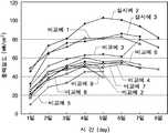
상기 실시예 1 내지 11, 및 비교예 1 내지 9의 연료 전지를 직접 메탄올 연료 전지 시스템으로 구성하여 상기 연료 전지의 성능을 50℃ 및 70℃에서 각각 측정하였다. 그 중, 실시예 2, 실시예 3, 및 비교예 1 내지 9의 연료 전지의 시간이 경과함에 따른 출력 밀도의 변화를 하기 표 3, 도 8, 및 도 9에 나타내었다.The fuel cells of Examples 1 to 11 and Comparative Examples 1 to 9 were constructed as a direct methanol fuel cell system, and the performance of the fuel cell was measured at 50 ° C and 70 ° C, respectively. Among these, the changes of the output densities of the fuel cells of Examples 2, 3, and Comparative Examples 1 to 9 over time are shown in Tables 3, 8, and 9 below.
[표 3][Table 3]
상기 표 3, 및 도 8 내지 9를 참조하면, 실시예 2 내지 3의 연료 전지가 비교예 1 내지 9의 연료 전지보다 출력 밀도가 향상되고, 전지의 수명도 연장됨을 확인할 수 있다.Referring to Table 3 and FIGS. 8 to 9, it can be seen that the fuel cells of Examples 2 to 3 have higher output densities and prolonged battery life than the fuel cells of Comparative Examples 1 to 9.
실시예 1, 및 실시예 4 내지 11의 경우에도 실시예 2 내지 3과 유사한 정도의 출력 밀도 결과를 얻었다.In the case of Example 1 and Examples 4 to 11, power density results similar to those in Examples 2 to 3 were obtained.
본 발명의 단순한 변형 또는 변경은 모두 이 분야의 통상의 지식을 가진 자에 의하여 용이하게 실시될 수 있으며 이러한 변형이나 변경은 모두 본 발명의 영역에 포함되는 것으로 볼 수 있다.It will be understood by those skilled in the art that various changes in form and details may be made therein without departing from the spirit and scope of the invention as defined by the appended claims.
도 1은 본 발명의 일 구체예에 따른 연료 전지용 막-전극 어셈블리의 단면을 모식적으로 나타낸 도면.BRIEF DESCRIPTION OF THE DRAWINGS FIG. 1 is a schematic cross-sectional view of a membrane-electrode assembly for a fuel cell according to one embodiment of the present invention. FIG.
도 2는 본 발명의 일 구체예에 따른 연료 전지 시스템의 구조를 개략적으로 나타낸 도면.2 is a schematic view showing the structure of a fuel cell system according to one embodiment of the present invention.
도 3a, 및 3b는 본 발명의 실시예 1에서 사용한 탄소 나노 튜브의 투과 전자 현미경(TEM) 사진.3A and 3B are transmission electron microscope (TEM) photographs of carbon nanotubes used in Example 1 of the present invention.
도 4a, 및 4b는 본 발명의 실시예 6에서 사용한 탄소 나노 파이버의 투과 전자 현미경 사진.4A and 4B are transmission electron micrographs of the carbon nanofibers used in Example 6 of the present invention.
도 5a, 및 5b는 본 발명의 실시예 2의 제2 촉매층의 주사 전자 현미경(SEM) 사진.5A and 5B are scanning electron microscope (SEM) photographs of the second catalyst layer of Example 2 of the present invention.
도 6a, 및 6b는 본 발명의 실시예 6의 제2 촉매층의 주사 전자 현미경 사진.6A and 6B are SEM micrographs of the second catalyst layer of Example 6 of the present invention.
도 7은 본 발명의 비교예 1의 제2 촉매층의 주사 전자 현미경 사진.7 is a scanning electron microscope (SEM) image of the second catalyst layer of Comparative Example 1 of the present invention.
도 8은 본 발명의 실시예 2 내지 3, 및 비교예 1 내지 9에서 제조한 연료 전지의 50℃에서의 출력 밀도의 변화를 나타내는 그래프.8 is a graph showing changes in power density at 50 DEG C of the fuel cell produced in Examples 2 to 3 and Comparative Examples 1 to 9 of the present invention.
도 9는 본 발명의 실시예 2 내지 3, 및 비교예 1내지 9에서 제조한 연료 전지의 70℃에서의 출력 밀도의 변화를 나타내는 그래프.9 is a graph showing changes in power density at 70 DEG C of the fuel cell produced in Examples 2 to 3 and Comparative Examples 1 to 9 of the present invention.
Claims (22)
Translated fromKoreanPriority Applications (2)
| Application Number | Priority Date | Filing Date | Title |
|---|---|---|---|
| KR1020070093636AKR100908720B1 (en) | 2007-09-14 | 2007-09-14 | Membrane-electrode assembly for fuel cell, and fuel cell system comprising same |
| US12/125,164US8278012B2 (en) | 2007-09-14 | 2008-05-22 | Membrane electrode assembly for fuel cell, and fuel cell system including the same |
Applications Claiming Priority (1)
| Application Number | Priority Date | Filing Date | Title |
|---|---|---|---|
| KR1020070093636AKR100908720B1 (en) | 2007-09-14 | 2007-09-14 | Membrane-electrode assembly for fuel cell, and fuel cell system comprising same |
Publications (2)
| Publication Number | Publication Date |
|---|---|
| KR20090028209A KR20090028209A (en) | 2009-03-18 |
| KR100908720B1true KR100908720B1 (en) | 2009-07-22 |
Family
ID=40454846
Family Applications (1)
| Application Number | Title | Priority Date | Filing Date |
|---|---|---|---|
| KR1020070093636AExpired - Fee RelatedKR100908720B1 (en) | 2007-09-14 | 2007-09-14 | Membrane-electrode assembly for fuel cell, and fuel cell system comprising same |
Country Status (2)
| Country | Link |
|---|---|
| US (1) | US8278012B2 (en) |
| KR (1) | KR100908720B1 (en) |
Families Citing this family (5)
| Publication number | Priority date | Publication date | Assignee | Title |
|---|---|---|---|---|
| CN102668201B (en)* | 2009-12-22 | 2015-05-20 | 3M创新有限公司 | Fuel cell electrode with nanostructured catalyst and dispersed catalyst sublayer |
| US10069148B2 (en)* | 2014-05-10 | 2018-09-04 | Daimler Ag | Fuel cell with selectively conducting anode |
| GB201912062D0 (en) | 2019-08-22 | 2019-10-09 | Johnson Matthey Fuel Cells Ltd | Catalysed membrane |
| CN112340833A (en)* | 2020-11-21 | 2021-02-09 | 江西挺进环保科技有限公司 | Restaurant wastewater pretreatment method |
| CN115064710B (en)* | 2022-06-28 | 2023-10-27 | 浙江锋源氢能科技有限公司 | Membrane electrode CCM, preparation method thereof, membrane electrode assembly MEA and fuel cell |
Citations (4)
| Publication number | Priority date | Publication date | Assignee | Title |
|---|---|---|---|---|
| JPS58165259A (en) | 1982-03-26 | 1983-09-30 | Furukawa Battery Co Ltd:The | Electrode-matrix combination and manufacture for matrix type fuel cell |
| KR20070014621A (en)* | 2005-07-29 | 2007-02-01 | 삼성에스디아이 주식회사 | Membrane-electrode assembly for direct oxidation fuel cell and direct oxidation fuel cell system comprising same |
| US20070134545A1 (en)* | 2005-12-12 | 2007-06-14 | Feng-Yi Deng | Membrane electrode assembly for fuel cells and fabrication method thereof |
| KR100738062B1 (en)* | 2006-05-16 | 2007-07-10 | 삼성에스디아이 주식회사 | Membrane Electrode Assembly and Fuel Cell Using the Same |
Family Cites Families (7)
| Publication number | Priority date | Publication date | Assignee | Title |
|---|---|---|---|---|
| US20020068213A1 (en)* | 2000-12-01 | 2002-06-06 | Honeywell International, Inc. Law Dept. Ab2 | Multiple layer electrode for improved performance |
| US20030134172A1 (en)* | 2002-01-11 | 2003-07-17 | Grande Wendy C. | Integrated fuel cell and electrochemical power system employing the same |
| US20040058227A1 (en)* | 2002-07-09 | 2004-03-25 | Matsushita Electric Industrial Co., Ltd. | Electrolyte membrane-electrode assembly for a fuel cell, fuel cell using the same and method of making the same |
| JP4707669B2 (en)* | 2004-09-21 | 2011-06-22 | シャープ株式会社 | MEMBRANE ELECTRODE COMPOSITE, MANUFACTURING METHOD THEREOF, FUEL CELL, ELECTRONIC DEVICE |
| US8313723B2 (en)* | 2005-08-25 | 2012-11-20 | Nanocarbons Llc | Activated carbon fibers, methods of their preparation, and devices comprising activated carbon fibers |
| JP2007080726A (en)* | 2005-09-15 | 2007-03-29 | Jsr Corp | Electrode-membrane assembly |
| JP2008027799A (en)* | 2006-07-24 | 2008-02-07 | Toyota Motor Corp | Fuel cell assembly, fuel cell, and fuel cell manufacturing method |
- 2007
- 2007-09-14KRKR1020070093636Apatent/KR100908720B1/ennot_activeExpired - Fee Related
- 2008
- 2008-05-22USUS12/125,164patent/US8278012B2/ennot_activeExpired - Fee Related
Patent Citations (4)
| Publication number | Priority date | Publication date | Assignee | Title |
|---|---|---|---|---|
| JPS58165259A (en) | 1982-03-26 | 1983-09-30 | Furukawa Battery Co Ltd:The | Electrode-matrix combination and manufacture for matrix type fuel cell |
| KR20070014621A (en)* | 2005-07-29 | 2007-02-01 | 삼성에스디아이 주식회사 | Membrane-electrode assembly for direct oxidation fuel cell and direct oxidation fuel cell system comprising same |
| US20070134545A1 (en)* | 2005-12-12 | 2007-06-14 | Feng-Yi Deng | Membrane electrode assembly for fuel cells and fabrication method thereof |
| KR100738062B1 (en)* | 2006-05-16 | 2007-07-10 | 삼성에스디아이 주식회사 | Membrane Electrode Assembly and Fuel Cell Using the Same |
Also Published As
| Publication number | Publication date |
|---|---|
| KR20090028209A (en) | 2009-03-18 |
| US8278012B2 (en) | 2012-10-02 |
| US20090075155A1 (en) | 2009-03-19 |
Similar Documents
| Publication | Publication Date | Title |
|---|---|---|
| US20070099069A1 (en) | Catalyst for a fuel cell, a method for preparing the same, and a membrane-electrode assembly for a fuel cell including the same | |
| KR100658688B1 (en) | Membrane-electrode assembly for fuel cell and fuel cell system comprising same | |
| KR20070098136A (en) | Membrane-electrode assembly for fuel cell and fuel cell system comprising same | |
| KR100908720B1 (en) | Membrane-electrode assembly for fuel cell, and fuel cell system comprising same | |
| KR102455396B1 (en) | Catalyst ink for forming electrode catalyst layer of fuel cell and manufacturing method thereof | |
| JP2006019300A (en) | FUEL CELL ELECTRODE, FUEL CELL, AND METHOD FOR PRODUCING FUEL CELL ELECTRODE | |
| JP2006252967A (en) | SOLID POLYMER ELECTROLYTE MEMBRANE FOR FUEL CELL AND FUEL CELL USING THE SAME | |
| KR20080047765A (en) | Membrane-electrode assembly for fuel cell, manufacturing method thereof, and fuel cell system comprising same | |
| KR101117630B1 (en) | Membrane-electrode assembly for fuel cell and method for preparating the same | |
| JP5204382B2 (en) | Cathode catalyst layer, membrane catalyst assembly, cathode gas diffusion electrode, membrane electrode assembly and polymer electrolyte fuel cell using the same | |
| KR100612233B1 (en) | Membrane / electrode assembly for fuel cell, manufacturing method thereof and fuel cell comprising same | |
| JP2006085984A (en) | MEA for fuel cell and fuel cell using the same | |
| KR100759430B1 (en) | Cathode catalyst for fuel cell, fuel cell membrane-electrode assembly comprising same and fuel cell system comprising same | |
| KR100778437B1 (en) | Cathode catalyst for fuel cell, fuel cell membrane-electrode assembly and fuel cell system comprising same | |
| JP2001185162A (en) | Fuel cell and its manufacturing method | |
| KR20070099935A (en) | Membrane-electrode assembly for fuel cell and fuel cell system comprising same | |
| CN116897449A (en) | Method for manufacturing catalyst layer for fuel cell | |
| KR20060104821A (en) | Catalyst for fuel cell, manufacturing method thereof, and fuel cell system comprising same | |
| KR101035620B1 (en) | Electrode for fuel cell, fuel cell comprising same and method for manufacturing electrode for fuel cell | |
| KR102873733B1 (en) | Membrane-electrode assembly for fuel cell comprising plate-shhaped porous silica and fuel cell comprising same | |
| KR100578977B1 (en) | Electrode for fuel cell, fuel cell comprising same and method for manufacturing electrode for fuel cell | |
| KR100982326B1 (en) | Membrane-electrode assembly for fuel cell, and fuel cell system comprising same | |
| KR101191634B1 (en) | Cathod catalyst for fuel cell, and membrane-electrode assembly for fuel cell and fuel cell system comprising same | |
| US20250046832A1 (en) | Membrane-electrode assembly and fuel cell comprising same | |
| KR20080047078A (en) | Active Method of Stack for Direct Oxidation Fuel Cell |
Legal Events
| Date | Code | Title | Description |
|---|---|---|---|
| A201 | Request for examination | ||
| PA0109 | Patent application | St.27 status event code:A-0-1-A10-A12-nap-PA0109 | |
| PA0201 | Request for examination | St.27 status event code:A-1-2-D10-D11-exm-PA0201 | |
| D13-X000 | Search requested | St.27 status event code:A-1-2-D10-D13-srh-X000 | |
| D14-X000 | Search report completed | St.27 status event code:A-1-2-D10-D14-srh-X000 | |
| E902 | Notification of reason for refusal | ||
| PE0902 | Notice of grounds for rejection | St.27 status event code:A-1-2-D10-D21-exm-PE0902 | |
| E13-X000 | Pre-grant limitation requested | St.27 status event code:A-2-3-E10-E13-lim-X000 | |
| P11-X000 | Amendment of application requested | St.27 status event code:A-2-2-P10-P11-nap-X000 | |
| P13-X000 | Application amended | St.27 status event code:A-2-2-P10-P13-nap-X000 | |
| R18-X000 | Changes to party contact information recorded | St.27 status event code:A-3-3-R10-R18-oth-X000 | |
| PG1501 | Laying open of application | St.27 status event code:A-1-1-Q10-Q12-nap-PG1501 | |
| E701 | Decision to grant or registration of patent right | ||
| PE0701 | Decision of registration | St.27 status event code:A-1-2-D10-D22-exm-PE0701 | |
| GRNT | Written decision to grant | ||
| PR0701 | Registration of establishment | St.27 status event code:A-2-4-F10-F11-exm-PR0701 | |
| PR1002 | Payment of registration fee | St.27 status event code:A-2-2-U10-U11-oth-PR1002 Fee payment year number:1 | |
| PG1601 | Publication of registration | St.27 status event code:A-4-4-Q10-Q13-nap-PG1601 | |
| R18-X000 | Changes to party contact information recorded | St.27 status event code:A-5-5-R10-R18-oth-X000 | |
| PR1001 | Payment of annual fee | St.27 status event code:A-4-4-U10-U11-oth-PR1001 Fee payment year number:4 | |
| FPAY | Annual fee payment | Payment date:20130621 Year of fee payment:5 | |
| PR1001 | Payment of annual fee | St.27 status event code:A-4-4-U10-U11-oth-PR1001 Fee payment year number:5 | |
| R18-X000 | Changes to party contact information recorded | St.27 status event code:A-5-5-R10-R18-oth-X000 | |
| FPAY | Annual fee payment | Payment date:20140701 Year of fee payment:6 | |
| PR1001 | Payment of annual fee | St.27 status event code:A-4-4-U10-U11-oth-PR1001 Fee payment year number:6 | |
| FPAY | Annual fee payment | Payment date:20150623 Year of fee payment:7 | |
| PR1001 | Payment of annual fee | St.27 status event code:A-4-4-U10-U11-oth-PR1001 Fee payment year number:7 | |
| FPAY | Annual fee payment | Payment date:20160617 Year of fee payment:8 | |
| PR1001 | Payment of annual fee | St.27 status event code:A-4-4-U10-U11-oth-PR1001 Fee payment year number:8 | |
| FPAY | Annual fee payment | Payment date:20170621 Year of fee payment:9 | |
| PR1001 | Payment of annual fee | St.27 status event code:A-4-4-U10-U11-oth-PR1001 Fee payment year number:9 | |
| LAPS | Lapse due to unpaid annual fee | ||
| PC1903 | Unpaid annual fee | St.27 status event code:A-4-4-U10-U13-oth-PC1903 Not in force date:20180715 Payment event data comment text:Termination Category : DEFAULT_OF_REGISTRATION_FEE | |
| PC1903 | Unpaid annual fee | St.27 status event code:N-4-6-H10-H13-oth-PC1903 Ip right cessation event data comment text:Termination Category : DEFAULT_OF_REGISTRATION_FEE Not in force date:20180715 | |
| R18-X000 | Changes to party contact information recorded | St.27 status event code:A-5-5-R10-R18-oth-X000 |