KR100905421B1 - Intelligent ventilation control system with energy savings - Google Patents
Intelligent ventilation control system with energy savingsDownload PDFInfo
- Publication number
- KR100905421B1 KR100905421B1KR1020070116973AKR20070116973AKR100905421B1KR 100905421 B1KR100905421 B1KR 100905421B1KR 1020070116973 AKR1020070116973 AKR 1020070116973AKR 20070116973 AKR20070116973 AKR 20070116973AKR 100905421 B1KR100905421 B1KR 100905421B1
- Authority
- KR
- South Korea
- Prior art keywords
- motor
- rotation angle
- filter
- fan motor
- suction pipe
- Prior art date
- Legal status (The legal status is an assumption and is not a legal conclusion. Google has not performed a legal analysis and makes no representation as to the accuracy of the status listed.)
- Expired - Fee Related
Links
Images


Classifications
- F—MECHANICAL ENGINEERING; LIGHTING; HEATING; WEAPONS; BLASTING
- F24—HEATING; RANGES; VENTILATING
- F24F—AIR-CONDITIONING; AIR-HUMIDIFICATION; VENTILATION; USE OF AIR CURRENTS FOR SCREENING
- F24F11/00—Control or safety arrangements
- F24F11/30—Control or safety arrangements for purposes related to the operation of the system, e.g. for safety or monitoring
- F24F11/46—Improving electric energy efficiency or saving
- F—MECHANICAL ENGINEERING; LIGHTING; HEATING; WEAPONS; BLASTING
- F24—HEATING; RANGES; VENTILATING
- F24F—AIR-CONDITIONING; AIR-HUMIDIFICATION; VENTILATION; USE OF AIR CURRENTS FOR SCREENING
- F24F1/00—Room units for air-conditioning, e.g. separate or self-contained units or units receiving primary air from a central station
- F24F1/0007—Indoor units, e.g. fan coil units
- F24F1/0071—Indoor units, e.g. fan coil units with means for purifying supplied air
- F24F1/0076—Indoor units, e.g. fan coil units with means for purifying supplied air by electric means, e.g. ionisers or electrostatic separators
- F—MECHANICAL ENGINEERING; LIGHTING; HEATING; WEAPONS; BLASTING
- F24—HEATING; RANGES; VENTILATING
- F24F—AIR-CONDITIONING; AIR-HUMIDIFICATION; VENTILATION; USE OF AIR CURRENTS FOR SCREENING
- F24F11/00—Control or safety arrangements
- F24F11/0001—Control or safety arrangements for ventilation
- F—MECHANICAL ENGINEERING; LIGHTING; HEATING; WEAPONS; BLASTING
- F24—HEATING; RANGES; VENTILATING
- F24F—AIR-CONDITIONING; AIR-HUMIDIFICATION; VENTILATION; USE OF AIR CURRENTS FOR SCREENING
- F24F11/00—Control or safety arrangements
- F24F11/30—Control or safety arrangements for purposes related to the operation of the system, e.g. for safety or monitoring
- F24F11/32—Responding to malfunctions or emergencies
- F24F11/39—Monitoring filter performance
- F—MECHANICAL ENGINEERING; LIGHTING; HEATING; WEAPONS; BLASTING
- F24—HEATING; RANGES; VENTILATING
- F24F—AIR-CONDITIONING; AIR-HUMIDIFICATION; VENTILATION; USE OF AIR CURRENTS FOR SCREENING
- F24F11/00—Control or safety arrangements
- F24F11/70—Control systems characterised by their outputs; Constructional details thereof
- F24F11/72—Control systems characterised by their outputs; Constructional details thereof for controlling the supply of treated air, e.g. its pressure
- F24F11/74—Control systems characterised by their outputs; Constructional details thereof for controlling the supply of treated air, e.g. its pressure for controlling air flow rate or air velocity
- F24F11/77—Control systems characterised by their outputs; Constructional details thereof for controlling the supply of treated air, e.g. its pressure for controlling air flow rate or air velocity by controlling the speed of ventilators
- F—MECHANICAL ENGINEERING; LIGHTING; HEATING; WEAPONS; BLASTING
- F24—HEATING; RANGES; VENTILATING
- F24F—AIR-CONDITIONING; AIR-HUMIDIFICATION; VENTILATION; USE OF AIR CURRENTS FOR SCREENING
- F24F8/00—Treatment, e.g. purification, of air supplied to human living or working spaces otherwise than by heating, cooling, humidifying or drying
- F24F8/10—Treatment, e.g. purification, of air supplied to human living or working spaces otherwise than by heating, cooling, humidifying or drying by separation, e.g. by filtering
- F24F8/108—Treatment, e.g. purification, of air supplied to human living or working spaces otherwise than by heating, cooling, humidifying or drying by separation, e.g. by filtering using dry filter elements
- F—MECHANICAL ENGINEERING; LIGHTING; HEATING; WEAPONS; BLASTING
- F24—HEATING; RANGES; VENTILATING
- F24F—AIR-CONDITIONING; AIR-HUMIDIFICATION; VENTILATION; USE OF AIR CURRENTS FOR SCREENING
- F24F2110/00—Control inputs relating to air properties
- F24F2110/50—Air quality properties
- F—MECHANICAL ENGINEERING; LIGHTING; HEATING; WEAPONS; BLASTING
- F24—HEATING; RANGES; VENTILATING
- F24F—AIR-CONDITIONING; AIR-HUMIDIFICATION; VENTILATION; USE OF AIR CURRENTS FOR SCREENING
- F24F2110/00—Control inputs relating to air properties
- F24F2110/50—Air quality properties
- F24F2110/52—Air quality properties of the outside air
- F—MECHANICAL ENGINEERING; LIGHTING; HEATING; WEAPONS; BLASTING
- F24—HEATING; RANGES; VENTILATING
- F24F—AIR-CONDITIONING; AIR-HUMIDIFICATION; VENTILATION; USE OF AIR CURRENTS FOR SCREENING
- F24F2110/00—Control inputs relating to air properties
- F24F2110/50—Air quality properties
- F24F2110/64—Airborne particle content
- F—MECHANICAL ENGINEERING; LIGHTING; HEATING; WEAPONS; BLASTING
- F24—HEATING; RANGES; VENTILATING
- F24F—AIR-CONDITIONING; AIR-HUMIDIFICATION; VENTILATION; USE OF AIR CURRENTS FOR SCREENING
- F24F2110/00—Control inputs relating to air properties
- F24F2110/50—Air quality properties
- F24F2110/65—Concentration of specific substances or contaminants
- F24F2110/66—Volatile organic compounds [VOC]
- F—MECHANICAL ENGINEERING; LIGHTING; HEATING; WEAPONS; BLASTING
- F24—HEATING; RANGES; VENTILATING
- F24F—AIR-CONDITIONING; AIR-HUMIDIFICATION; VENTILATION; USE OF AIR CURRENTS FOR SCREENING
- F24F2110/00—Control inputs relating to air properties
- F24F2110/50—Air quality properties
- F24F2110/65—Concentration of specific substances or contaminants
- F24F2110/70—Carbon dioxide
- Y—GENERAL TAGGING OF NEW TECHNOLOGICAL DEVELOPMENTS; GENERAL TAGGING OF CROSS-SECTIONAL TECHNOLOGIES SPANNING OVER SEVERAL SECTIONS OF THE IPC; TECHNICAL SUBJECTS COVERED BY FORMER USPC CROSS-REFERENCE ART COLLECTIONS [XRACs] AND DIGESTS
- Y02—TECHNOLOGIES OR APPLICATIONS FOR MITIGATION OR ADAPTATION AGAINST CLIMATE CHANGE
- Y02B—CLIMATE CHANGE MITIGATION TECHNOLOGIES RELATED TO BUILDINGS, e.g. HOUSING, HOUSE APPLIANCES OR RELATED END-USER APPLICATIONS
- Y02B30/00—Energy efficient heating, ventilation or air conditioning [HVAC]
- Y02B30/70—Efficient control or regulation technologies, e.g. for control of refrigerant flow, motor or heating
Landscapes
- Engineering & Computer Science (AREA)
- Chemical & Material Sciences (AREA)
- Combustion & Propulsion (AREA)
- Mechanical Engineering (AREA)
- General Engineering & Computer Science (AREA)
- Physics & Mathematics (AREA)
- Fluid Mechanics (AREA)
- Ventilation (AREA)
- Filtering Of Dispersed Particles In Gases (AREA)
- Air Conditioning Control Device (AREA)
- Filtering Materials (AREA)
Abstract
Translated fromKoreanDescription
Translated fromKorean본 발명은 환기 제어에 관한 것으로, 보다 상세하게는 실외 공기의 신선도에 비례하여 복합필터의 유동 각도를 제어하고, 유동 각도에 대응하는 배출 공기의 압력에 따라 팬모터의 전력 제어를 수행할 수 있는 에너지 절감 기능을 갖는 지능형 환기 제어 시스템에 관한 것이다.The present invention relates to ventilation control, and more particularly, to control the flow angle of the composite filter in proportion to the freshness of the outdoor air, and to control the power of the fan motor according to the pressure of the exhaust air corresponding to the flow angle. An intelligent ventilation control system having an energy saving function.
일반적으로, 건물로 적용되는 환기 유니트 구조는 도 1 내지 도 2에 도시한 바와 같이, 하우징(1) 내의 소정위치에 탈부착 가능토록 장착되며 또한 일측을 힌지점으로 내부가 개폐되는 제1 및 제2지지틀(30)(32)과, 상기 제1지지틀(30)과 제2지지틀(32)과의 사이로 탈부착 가능토록 개재되어 공기 중에 부유하는 이물질을 필터링하는 카본 필터(34)로 구성되어 있다.In general, the ventilation unit structure applied to the building is, as shown in Figures 1 to 2, the first and the second is mounted so as to be detachable at a predetermined position in the housing (1) and the inside is opened and closed by a hinge point It is composed of a
즉, 상기 제1 및 제2지지틀(30)(32)은 일정두께를 가진 사각형상의 알루미늄재질로 각각 이루어져 있고, 그 중앙에는 공기가 통과되도록 개구부가 형성되며, 이들 사각 외주면 일측에는 상기 제1 및 제2지지틀(30)(32)이 서로 대향되는 소정각도로 여닫이방식에 의해 개폐되도록 상하 일정간격을 두고 복수의 경첩이 각각 설치되어 있다. 그리고, 상기 제1지지틀(30)의 중앙 개구 면적에는 통과되는 공기중에 부유하는 이물질 중 일부가 정전기(靜電氣)에 의해 필터링되게 함과 동시에 제1지지틀(30)과 제2지지틀(32) 사이에 개재된 상기 카본 필터(34)가 외부로 돌출되지 않게 잡아주도록 정전망(38)이 설치되고, 상기 제2지지틀(32)의 중앙 개구 면적에는 제1지지틀(30)과 제2지지틀(32) 사이에 개재된 상기 카본 필터(34)가 외부로 돌출되지 않게 잡아주도록 알루미늄재질의 지지망(40)이 설치되어 있다.That is, the first and
이때, 상기 정전망(38)은 상기 지지망(40) 보다 작은 메시(Mesh)로 이루어져 있다. 또, 상기 제1지지틀(30)의 사각 외주면에 대하여 상기 복수의 경첩과 대향되는 반대편 중앙에는 힌지점을 중심으로 상하 회동되면서 제1지지틀(30)과 제2지지틀(32)이 서로 결합 또는 분리되도록 캐처(Catcher)(42)가 설치되어있다. 상기 캐처(42)는 상기 제1지지틀(30)의 두께와 제2지지틀(32)의 두께가 합쳐진 폭을 동시 잡아주거나 동시 분리될 수 있는 폭을 가진 (ㄷ)자 형상으로 이루어져 있고, 그 일측에는 상기 제1지지틀(30)의 사각 외주면 일측과 캐처(42)가 리벳(44)에 의해 힌지되도록 리벳팅 홀을 가진 연장부가 일체로 돌설되어 있다.In this case, the
전술된 종래 환기 유니트의 동작을 살펴 보면, 하우징(1)내에 제1 및 제2지지틀(30)(32)을 매개로 카본 필터(34)를 설치한 상태에서 블로워(13)를 가동시키면, 이 블로워(13)의 송풍압력에 따라 실외의 공기가 제1덕트(7a)와 연결된 공기 유입구(1a)를 통해 하우징(1)의 내부로 흡입되면서 제1 및 제2지지틀(30)(32)에 의해 고정된 정전망(38), 카본 필터(34), 지지망(40)을 순차적으로 통과한다.Looking at the operation of the conventional ventilation unit described above, when the
이때, 정전망(38)은 공기가 통과할 때 공기 중에 부유하는 이물질을 정전기 에 의해 흡착 제거하게 되고, 카본 필터(34)는 정전망(38)에서 필터링되지 않은 공기중의 이물질을 필터링하면서 순수한 공기(청정 공기)만을 통과시키게 된다. 그리고, 상기 카본 필터(34)를 통과한 청정 공기는 블로워(13)를 경유하여 하우징(1)의 공기유출구(1b)와 연결된 제2덕트(7b)로 유입되고, 제2덕트(7b)를 따라 흐르는 청정 공기는 실내 천정을 통해 실내로 토출됨으로써 실내의 공기 청정도를 높인다.At this time, the
한편, 카본 필터(34)를 분리하기 위해서는, 먼저 하우징(1)의 일측에 설치된 도어를 통해 제1 및 제2지지틀(30)(32)을 외부로 인출시킨 후, 제1지지틀(30)에 힌지된 캐처(42)를 일 방향으로 잡아당기면, 이 캐처(42)는 그 연장부와 제1지지틀(30)을 연결하는 리벳(44)을 힌지점으로 하여 일 방향으로 회동되면서 제1지지틀(30)과 제2지지틀(32)이 서로 분리될 수 있도록 잠금 상태가 해제된다.On the other hand, in order to separate the
이러한 상태에서 제1지지틀(30)과 제2지지틀(32)을 벌리면, 제1지지틀(30)과 제2지지틀(32)은 그 외측면에 고정된 복수의 경첩을 중심으로 소정각도로 벌어지게 되면서 그 사이에 삽입된 카본 필터(34)와 분리되고, 이 카본 필터(34)는 제1 및 제2지지틀(30)(32)과 분리된다.In this state, when the
전술된 바와 같이, 종래 적용되는 환기 유니트 구조는, 환기의 효율성을 높이기 위한 구조적 관점에서 환기의 주요 구성 요소인 필터의 탈착이 용이하도록 하고 있다. 그러나, 이는 필터의 교환을 통해 공기 정화의 기능을 실현하고 있기 때문에, 필터의 세척 주기가 둔화될 경우 팬모터의 구동 부하가 높아져 소비전력이 증가하는 문제가 발생된다. 또한, 필터의 세척은 기본적으로 인위적인 행위에 기반할 수밖에 없어 인력 에너지 손실을 유발한다는 문제가 지적되고 있다.As described above, the conventionally applied ventilation unit structure facilitates the detachment of the filter, which is a major component of the ventilation, from a structural point of view to increase the efficiency of the ventilation. However, since the air purifying function is realized through the replacement of the filter, when the cleaning cycle of the filter is slowed, the driving load of the fan motor is increased, resulting in an increase in power consumption. In addition, it is pointed out that the cleaning of the filter is basically based on artificial behavior, causing human energy loss.
본 발명은 이와 같은 문제를 해결하기 위해 창출된 것으로, 본 발명의 목적은 실외 공기의 신선도를 근거로 필터의 유동 각도를 조절함으로써, 배출 공기압을 저하시켜 팬모터의 소비전력을 절감시킬 수 있는 에너지 절감 기능을 갖는 지능형 환기 제어 시스템을 제공함에 있다.The present invention was created to solve such a problem, and an object of the present invention is to adjust the flow angle of the filter based on the freshness of the outdoor air, thereby reducing the exhaust air pressure to reduce the power consumption of the fan motor It is to provide an intelligent ventilation control system with a saving function.
본 발명의 다른 목적은, 필터의 교체 주기를 증대시켜 필터링의 수명을 높이도록 함에 따라, 운영 관리를 위한 비용 절감을 유도할 수 있는 에너지 절감 기능을 갖는 지능형 환기 제어 시스템을 제공함에 있다.Another object of the present invention is to provide an intelligent ventilation control system having an energy saving function that can lead to a cost reduction for operation management by increasing the replacement cycle of the filter to increase the life of the filtering.
상기 목적을 달성하기 위한 본 발명에 따른 에너지 절감 기능을 갖는 지능형 환기 제어 시스템은, 소정 형상의 흡입관 및 배기관을 포함하여, 상기 흡입관의 초입부로 프리필터(Pre-Filter)가 배치되고, 상기 프리필터의 후방으로 복합필터가 구비된 환기 제어 시스템에 있어서, 상기 흡입관 및 배기관 사이로 장착되어 외부의 제어신호에 따라 상기 흡입관의 내부 흡입 압력을 선형적으로 제어하는 팬모터; 상기 복합필터의 회동 각도를 제어하기 위한 회전각 모터; 외부 공기의 신선도를 측정하여 이를 전기적 신호로 변환 출력하는 외기 센서; 및 상기 외기 센서의 출력 신호에 근거하여 상기 복합필터의 개구 각도를 제어하고 상기 흡입관 내부의 압력을 가변시키기 위해, 상기 회전각 모터 및 팬모터를 구동 제어하기 위한 제어장치로 구성되는 것을 특징으로 한다.Intelligent ventilation control system having an energy saving function according to the present invention for achieving the above object, including a suction pipe and the exhaust pipe of a predetermined shape, a pre-filter (Pre-Filter) is disposed at the beginning of the suction pipe, the pre-filter A ventilation control system having a composite filter at a rear side thereof, comprising: a fan motor mounted between the suction pipe and the exhaust pipe to linearly control the internal suction pressure of the suction pipe according to an external control signal; A rotation angle motor for controlling a rotation angle of the composite filter; An outside air sensor which measures the freshness of the outside air and converts it into an electrical signal; And a control device for controlling driving of the rotation angle motor and the fan motor to control the opening angle of the composite filter and to vary the pressure in the suction pipe based on the output signal of the outside air sensor. .
구체적으로, 상기 제어장치는 상기 적어도 하나 이상의 회전각 모터를 포함하여 상기 팬 모터의 회전 각도 및 회전 속도를 구현하기 위한 정격신호를 공급하는 각각의 드라이버; 상기 각 회전각 모터 및 팬 모터로 장착되어 모터의 회전 각도 및 회전 속도를 검출하는 모터상태 검출센서; 상기 모터상태 검출센서 및 외기 센서로부터 검출된 신호를 정형화된 신호로 변환하는 인터페이스; 상기 외기센서에서 검출된 외부 공기의 신선도에 비례하여 외부 공기에 대한 실내 유입 여부 및 유입 량을 수치화된 정보로 보유하고, 상기 외부 공기에 대한 실내 유입 량 정보를 토대로 상기 적어도 하나 이상의 회전각 모터의 회전 각도와 상기 팬 모터의 모터 회전 수를 정의하기 위한 테이블 정보가 저장된 프로그램 메모리; 및 상기 외기센서의 검출 결과를 포함하여 상기 적어도 하나 이상의 회전각 모터 및 팬 모터의 모터상태 검출 결과를 토대로 상기 테이블 정보에 따른 모터 제어신호를 상기 드라이버로 공급하기 위한 제어부로 구성되는 것을 특징으로 한다.Specifically, the control device includes a driver for supplying a rated signal for implementing the rotation angle and rotation speed of the fan motor including the at least one rotation angle motor; A motor state detection sensor mounted to each rotation angle motor and a fan motor to detect a rotation angle and a rotation speed of the motor; An interface for converting a signal detected from the motor state detection sensor and an outside sensor into a standardized signal; The inflow and inflow amount of the indoor air to the outside air in proportion to the freshness of the outside air detected by the outside sensor is stored as numerical information, and based on the indoor inflow amount information to the outside air of the at least one rotation angle motor A program memory storing table information for defining a rotation angle and a motor rotation speed of the fan motor; And a controller for supplying a motor control signal according to the table information to the driver based on a motor state detection result of the at least one rotation angle motor and a fan motor including a detection result of the external air sensor. .
본 발명은 고정 설치되는 프리필터와 실외 공기의 신선도에 따라 회전각도를 달리하는 복합필터의 필터링 과정을 통해, 복합필터에 의한 팬모터의 토출 부하를 격감시켜 팬모터의 소비 전력을 저하시키는 효과를 제공한다. 또한 본 발명은 복합필터의 회전각도 제어를 통해 필터의 사용 수명을 연장할 뿐만 아니라, 시스템 관리적 측면에서 불필요한 인력 낭비 및 운영비를 절감할 수 있는 효과를 갖는다.The present invention has the effect of reducing the power consumption of the fan motor by reducing the discharge load of the fan motor by the composite filter through the filtering process of the fixed filter and the composite filter having a different rotation angle according to the freshness of the outdoor air. to provide. In addition, the present invention not only extends the service life of the filter by controlling the rotation angle of the composite filter, but also has an effect of reducing unnecessary manpower waste and operating costs in terms of system management.
이하, 본 발명을 첨부된 예시도면에 의거 상세히 설명하면 다음과 같다.Hereinafter, the present invention will be described in detail with reference to the accompanying drawings.
도 3은 본 발명에 따른 환기 제어 시스템을 나타낸 사시도이다. 도시된 바와 같이, 환기제어 시스템은 외부의 공기를 필터링하여 내부로 토출시키기 위한 구조로써, 흡입구의 초입부로 프리필터(Pre-Filter)가 배치되고, 상기 프리필터의 후방으로 적어도 하나 이상의 복합필터가 구비된다. 본 발명은 전술된 복합필터의 회전각 제어 및 필터링의 토출 압력을 제어하는 것으로, 소정 형상의 흡입관(305) 및 배기관(303)을 형성하며, 상기 흡입관(305) 및 배기관(303) 사이로 장착되어 외부의 제어신호에 따라 상기 흡입관(305)의 내부 흡입 압력을 선형적으로 제어하는 팬모터(301)와, 상기 복합필터(313)의 회동 각도를 제어하기 위한 회전각 모터(309)를 포함하며, 상기 팬모터(301) 및 회전각 모터(309)의 동작 제어를 위해 이하 설명될 제어장치로 구성된다.3 is a perspective view showing a ventilation control system according to the present invention. As shown, the ventilation control system is a structure for filtering the outside air to discharge the inside, a pre-filter (pre-filter) is disposed at the beginning of the suction port, at least one of the composite filter to the rear of the pre-filter It is provided. The present invention controls the discharge pressure of the rotation angle control and filtering of the above-described composite filter, and forms a
상기 제어장치는 관리자의 스위칭 신호를 인가받아 상기 팬모터(301)의 회전 속도를 제어하거나, 상기 회전각 모터(309)의 회동 각도를 설정 제어한다. 이러한 제어장치의 시스템 운영 알고리즘은 수동 모드에 따른 것으로, 본 발명은 수동 모드 이외에 자동화된 환기 제어가 이루어질 수 있음은 물론이다.The control device receives a switching signal from the manager to control the rotation speed of the
따라서, 상기 제어장치는 외부 공기에 대한 신선도를 측정하기 위한 실외공기 감지센서와 연동하며, 상기 실외공기 감지센서의 검출 신호에 근거하여 상기 팬모터(301) 및 회전각 모터(309)의 운영제어가 가능하다.Therefore, the control device is interlocked with the outdoor air sensor for measuring the freshness of the outside air, the operation control of the
한편, 상기 회전각 모터(309)는 DC, AC 및 스텝핑 모터 중 어느 하나가 적용될 수 있으며, 상기 회전각 모터(309)가 DC 또는 AC 모터일 경우, 인버터 또는 컨버터가 부가적으로 장착될 뿐만 아니라, 소정의 감속 비를 갖는 감속 기어를 포함 하고, 상기 감속 기어의 축 단으로 회전 각도를 인지하기 위한 포지셔닝 센서 또는 포터 커플러 등이 내설될 수 있을 것이다.Meanwhile, any one of DC, AC, and stepping motors may be applied to the
또한, 상기 회전각 모터(309)는 도시된 바와 같이, 제1회전각 모터(309) 및 제2회전각 모터(307)를 보유할 수 있으며, 이에 따라 제1회전각 모터(309)와 연동하는 제1 복합필터(313) 및 제2 복합필터(311)가 장착될 수 있다. 본 발명에 따른 환기제어 시스템은 장착 규모 또는 필터링 규모에 따라 다수 개의 복합필터를 보유하고, 각 복합필터의 회전 각도를 제어할 수 있음은 당연할 것이다.In addition, the
상기 복합필터는 다수 종류의 미세먼지 및 가스상 오염물질 예컨대,VOC, NO2, ozone 등의 물질을 포집하기 위한 것으로, 도시된 바와 같이 다수의 필터를 중첩시켜 복합필터로 사용된다. 따라서, 본 발명에서 제시되는 복합필터는 오염물질의 종류 또는 미세먼지의 크기에 따른 각 필터를 복합한 필터 구조로써, 지역별 또는 시대적 상황에 따라 복합필터의 구조적 변경은 본 발명의 기술적 요지를 벗어나지 않을 것이다.The composite filter is for collecting various kinds of fine dust and gaseous contaminants such as VOC, NO 2, ozone, and the like, and is used as a composite filter by overlapping a plurality of filters as shown. Therefore, the composite filter proposed in the present invention is a filter structure that combines each filter according to the type of pollutant or the size of the fine dust, and the structural change of the composite filter according to the regional or era situation does not depart from the technical gist of the present invention. will be.
도 4는 본 발명에 따른 환기제어 시스템의 주요 구성을 나타낸 도면이다. 도시된 바와 같이, 적어도 하나 이상의 회전각 모터 예컨대, 제1 회전각 모터(309) 및 제2 회전각 모터(307)를 포함하여 상기 팬 모터(301)의 회전 각도 및 회전 속도를 구현하기 위한 정격신호를 공급하는 각각의 드라이버(405)와, 외부 공기의 신선도를 기 설정된 검출 패턴에 따라 추출하고, 이를 전기적 신호로 변환하는 외기 센서(407)와, 상기 각 회전각 모터(307) 및 팬 모터(301)로 장착되어 모터의 회전 각도 및 회전 속도를 검출하는 모터상태 검출센서(미도시함)와, 상기 모터상태 검출 센서 및 외기 센서(407)로부터 검출된 신호를 정형화된 신호로 변환하는 인터페이스(409)와, 상기 외기센서(407)에서 검출된 외부 공기의 신선도에 비례하여 외부 공기에 대한 실내 유입 여부 및 유입 량을 수치화된 정보로 보유하고, 상기 외부 공기에 대한 실내 유입 량 정보를 토대로 상기 적어도 하나 이상의 회전각 모터의 회전 각도와 상기 팬 모터(301)의 모터 회전 수를 정의하기 위한 테이블 정보가 저장된 프로그램 메모리(403)와, 상기 외기센서(407)의 검출 결과를 포함하여 상기 적어도 하나 이상의 회전각 모터 및 팬 모터(301)의 모터상태 검출 결과를 토대로 상기 테이블 정보에 따른 모터 제어신호를 상기 드라이버(405)로 공급하기 위한 제어부(401)로 구성된다.4 is a view showing the main configuration of the ventilation control system according to the present invention. As shown, at least one rotation angle motor, such as a first
여기서, 상기 제어부(401)는 팬모터(301)의 소비 전력을 감소시키기 위한 제어 수단으로 사용되는데, 상기 회전각 모터(307,309)와 연동하는 각각의 복합필터에 의한 흡입 부하를 방지하기 위한 것이다. 여기서, 각각의 복합필터 즉, 제1 복합필터(313) 및 제2 복합필터(311)는 5㎛ 이상의 미립자를 포집하기 위한 메쉬 구조를 갖기 때문에, 상기 팬모터(301)의 구동 부하는 소비전력과 연관된다. 따라서, 상기 제어부(401)는 외기의 신선도에 따라 팬모터(301)의 구동 부하를 줄이기 위해, 상기 회전각 모터를 이용한 복합필터의 회전 각도를 제어한다.Here, the
따라서, 상기 제어부(401)는 적어도 하나 이상의 회전각 모터를 각각으로 제어함이 바람직할 것이다. 예컨대, 제1 복합필터(313)를 개방시켜 제2 복합필터(311)만을 사용할 수 있으며, 또는 제1 복합필터(313)를 일부 개방시켜 흡입 공기의 압력 부하를 줄일 수 있을 것이다. 이와 같은 기본 원리를 토대로, 상기 제어 부(401)는 상기 팬모터(301)의 회전 속도가 상기 회전각 모터의 개구 각도에 반비례하도록 제어한다.Accordingly, the
한편, 상기 외기센서(407)는 외부 공기의 오염도를 측정하기 위한 센서로써, 미세먼지 오염도, 이산화탄소 오염도, 휘발성 유기화합물 오염도 등을 측정한다. 따라서, 상기 프로그램 메모리(403)는 전술된 오염도에 대한 기준치 정보를 포함하고 있으며, 또한 기준치 정보와 측정치 정보와의 편차값을 토대로 복합필터의 개폐 여부 및 개폐 각도를 설정하는 제어정보를 갖는다. 예컨대, 상기 프로그램 메모리(403)는 미세먼지 평균오염도에 대한 기준치로서 150㎍/㎥를 설정하고, 이산화탄소의 오염도에 대한 기준치로서 1000ppm을 설정하며, 휘발성유기화합물 오염도의 기준치로서 500㎍/㎥을 설정할 수 있다.On the other hand, the
여기서, 상기 휘발성유기화합물은 다수 종류의 물질이 배합되어 있기 때문에, 외기센서(407)는 모든 물질에 대한 기준치 초과 여부를 판단하지 못한다. 따라서, 벤젠, 톨루엔, 포름알데히드와 부유세균 등과 같은 특정 유해 물질에 대한 유해도를 근거로 외부 공기의 신선도를 대치할 수 있을 것이다.Here, since the volatile organic compound is mixed with a plurality of kinds of substances, the
이하, 본 발명의 동작을 설명한다.The operation of the present invention will be described below.
먼저, 상기 제어부(401)는 모터상태 검출센서로부터 제1 회전각 모터(309) 및 제2 회전각 모터(309)의 회전 각도를 측정한다. 이는 상기 제1 복합필터(313) 및 제2 복합필터(311)가 초기 각도로 설정되어 있는지를 판단하는 것으로, 각 복합필터는 프리필터(315)와 수평을 유지한다.First, the
또한, 상기 제어부(401)는 외기센서(407)로부터 외부 공기에 대한 신선도를 측정하며, 측정결과는 상기 인터페이스(409)를 통해 제공받는다. 전술한 바와 같이, 외부 공기에 대한 신선도는 미세먼지 오염도, 이산화탄소 오염도, 휘발성 유기화합물 오염도 등이 기준치 이하로 검출되는지를 판단한다. 필요에 따라, 상기 외기센서(407)는 상기한 모든 유해물질에 대한 오염도를 측정할 수 있는 다수의 센서로 구성될 수 있으나, 어느 한 종류의 오염 물질을 검출하기 위한 하나의 센서가 적용될 수 있을 것이다.In addition, the
상기 제어부(401)는 이와 같은 상기 외기센서(407)로부터 검출된 오염도 정보가 기준치를 넘는지를 판단하기 위해 상기 프로그램 메모리(403)로 저장된 테이블 정보를 페치한다. 상기 테이블 정보는 각 오염도에 대한 기준치 정보를 저장하고 있으며, 제어부(401)는 외기센서(407)로부터 검출된 오염도와 기준치 정보를 비교하여 현재의 외부 공기에 대한 실내(내부)로의 유입 여부를 결정한다.The
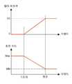
즉, 도 5에 도시된 바와 같이 공기 중의 오염도가 기준치보다 높을 경우, 이는 도면의 기준치 이하의 범위를 나타내는 것으로, 상기 제어부(401)는 제1 회전각 모터(309) 및 제2 회전각 모터(307)를 제어하여 상기 제1 복합필터(313) 및 제2 복합필터(311)의 회동 각도를 0°로 유지한다. 이는 각 복합필터를 개방하지 않는 것으로, 복합필터를 통해 외부 공기를 필터링하기 위한 것이다.That is, when the pollution degree in the air is higher than the reference value as shown in FIG. 5, this indicates a range below the reference value in the drawing, and the
이때, 상기 제어부(401)는 팬모터(301)를 구동하기 위한 명령을 지시하며, 드라이버(405)는 제어부(401)의 명령에 따라 상기 팬모터(301)로 최대 속도를 유지하도록 정격 전력을 제공한다.At this time, the
한편, 상기 제어부(401)로 유입되는 외기센서(407)의 검출 신호가 기준치 이 상 예컨대, 미세먼지 오염도가 150㎍/㎥ 이하이고, 이산화탄소의 오염도가 1000ppm 이하이며, 휘발성유기화합물 오염도가 500㎍/㎥ 이하일 경우, 상기 제어부(401)는 복합필터의 개구 각도를 증가시키고, 상기 팬모터의 회전 속도를 감소시킨다. 상기 복합필터의 개구 각도는 최대 90°이고, 상기 팬모터(301)의 최소 속도는 아이들링 상태이다. 여기서, 상기 팬모터(301)는 정지 상태를 유지하여도 본 발명의 요지를 벗어나지 않을 것이다.On the other hand, the detection signal of the
여기서, 상기 복합필터의 개구 각도는 프로그램 메모리(403)로 기 설정되어 있으나, 상기 복합필터가 둘 이상 존재할 경우 각 복합필터의 개구 각도의 합산 결과를 기 설정된 개구 각도로 상정할 수 있을 것이다. 즉, 프로그램 메모리(403)로 설정된 복합필터의 개구 각도가 30°일 경우, 제1 복합필터(313)를 30°개구하고, 제2 복합필터(311)를 0°개구하도록 제어하거나, 제1 복합필터(313)를 15°개구하고, 제2 복합필터(311)를 15°개구하도록 제어할 수 있을 것이다.Here, although the opening angle of the composite filter is previously set in the
본 발명에서 복합필터의 개구 각도와 팬모터(301)의 회전 속도가 반비례하는 것은, 복합필터의 개구로 인한 흡입 부하만큼 팬모터(301)의 회전 속도를 저감시키기 위한 것이다. 따라서, 복합필터의 메쉬 구조, 환기 시스템의 흡입관 크기, 팬모터의 용량 등에 근거하여, 복합필터의 개구 각도 및 팬모터의 회전 속도에 대한 반비례 관계는 그 크기가 변형될 수 있을 것이다.In the present invention, the opening angle of the composite filter and the rotation speed of the
이상 설명된 바와 같이, 본 발명에 따른 에너지 절감 기능을 갖는 지능형 환기 제어 시스템은, 공기 정화의 실용성을 부여하면서 시스템을 운영하기 위한 전기 에너지를 절감하고, 운영 시스템의 효율성을 높여 산업적 이용 가치가 충분히 가미될 것으로 판단된다.As described above, the intelligent ventilation control system having an energy saving function according to the present invention, while saving the electrical energy for operating the system while giving the practicality of air purification, and increase the efficiency of the operating system is sufficient industrial utilization value It is expected to be added.
도 1 및 도 2는 종래 환기 유니트 구조를 설명하기 위한 도면이다.1 and 2 are views for explaining a conventional ventilation unit structure.
도 3은 본 발명에 따른 지능형 환기 시스템을 설명하기 위한 사시도이다.3 is a perspective view for explaining the intelligent ventilation system according to the present invention.
도 4는 도 3의 주요 기능을 설명하기 위한 구성도이다.4 is a configuration diagram illustrating the main functions of FIG. 3.
도 5는 본 발명에 따른 제어부의 제어 패턴을 설명하기 위한 그래프이다.5 is a graph illustrating a control pattern of the controller according to the present invention.
<주요 도면에 대한 부호의 설명><Explanation of symbols for main drawings>
301 : 팬모터 307 : 제2 회전각 모터301: fan motor 307: second rotation angle motor
309 : 제1 회전각 모터 311 : 제2 복합필터309: first rotation angle motor 311: second composite filter
313 : 제1 복합필터 401 : 제어부313: first composite filter 401: control unit
403 : 프로그램 메모리 405 : 드라이버403: program memory 405: driver
407 : 외기센서 409 : 인터페이스407: outside sensor 409: interface
Claims (5)
Translated fromKoreanPriority Applications (6)
| Application Number | Priority Date | Filing Date | Title |
|---|---|---|---|
| KR1020070116973AKR100905421B1 (en) | 2007-11-16 | 2007-11-16 | Intelligent ventilation control system with energy savings |
| EP08850092.1AEP2225498B1 (en) | 2007-11-16 | 2008-09-19 | Intelligent energy saving ventilation control system |
| PCT/KR2008/005565WO2009064074A1 (en) | 2007-11-16 | 2008-09-19 | Intelligent energy saving ventilation control system |
| JP2010524794AJP5379798B2 (en) | 2007-11-16 | 2008-09-19 | Intelligent ventilation control system with energy saving function |
| US12/677,808US8496514B2 (en) | 2007-11-16 | 2008-09-19 | Intelligent energy saving ventilation control system |
| CN2008801009665ACN101861498B (en) | 2007-11-16 | 2008-09-19 | Intelligent energy saving ventilation control system |
Applications Claiming Priority (1)
| Application Number | Priority Date | Filing Date | Title |
|---|---|---|---|
| KR1020070116973AKR100905421B1 (en) | 2007-11-16 | 2007-11-16 | Intelligent ventilation control system with energy savings |
Publications (2)
| Publication Number | Publication Date |
|---|---|
| KR20090050504A KR20090050504A (en) | 2009-05-20 |
| KR100905421B1true KR100905421B1 (en) | 2009-07-02 |
Family
ID=40638890
Family Applications (1)
| Application Number | Title | Priority Date | Filing Date |
|---|---|---|---|
| KR1020070116973AExpired - Fee RelatedKR100905421B1 (en) | 2007-11-16 | 2007-11-16 | Intelligent ventilation control system with energy savings |
Country Status (6)
| Country | Link |
|---|---|
| US (1) | US8496514B2 (en) |
| EP (1) | EP2225498B1 (en) |
| JP (1) | JP5379798B2 (en) |
| KR (1) | KR100905421B1 (en) |
| CN (1) | CN101861498B (en) |
| WO (1) | WO2009064074A1 (en) |
Cited By (5)
| Publication number | Priority date | Publication date | Assignee | Title |
|---|---|---|---|---|
| KR20160110288A (en)* | 2016-08-05 | 2016-09-21 | 두산중공업 주식회사 | Debris removal device of a gas turbine |
| KR101811100B1 (en)* | 2015-03-09 | 2017-12-20 | 두산중공업 주식회사 | Debris removal device of a gas turbine |
| KR102323036B1 (en) | 2020-08-24 | 2021-11-05 | 중앙대학교 산학협력단 | Air cleaning method considering the floating characteristics of particulate matter |
| KR20220028304A (en) | 2020-08-28 | 2022-03-08 | 주식회사 하늘항공 | Drone takeoff and landing station unit with automatic charging |
| US12270144B2 (en) | 2018-01-23 | 2025-04-08 | Samsung Electronics Co., Ltd. | Clothing management apparatus |
Families Citing this family (35)
| Publication number | Priority date | Publication date | Assignee | Title |
|---|---|---|---|---|
| US8362737B2 (en)* | 2008-09-08 | 2013-01-29 | Nidec Motor Corporation | Blower motor for HVAC systems |
| US8294393B2 (en)* | 2008-09-08 | 2012-10-23 | Nidec Motor Corporation | Blower motor for HVAC systems |
| GB0912082D0 (en)* | 2009-07-10 | 2009-08-19 | Ubisense Ltd | Lacation sysstem |
| TWI507608B (en)* | 2013-02-08 | 2015-11-11 | Delta Electronics Inc | Variable frequency motor device and fan equipment thereof |
| KR101444323B1 (en)* | 2013-02-22 | 2014-09-26 | 삼성중공업 주식회사 | Cargo tank air conditioning system |
| JP6156628B2 (en)* | 2013-04-17 | 2017-07-05 | 株式会社Ihi | Flue gas denitration apparatus and flue gas denitration method |
| CN104422021A (en)* | 2013-08-26 | 2015-03-18 | 布朗(上海)环境技术有限公司 | Whole-house efficient fresh air filtering main machine for treating indoor PM2.5 |
| CN106196415B (en)* | 2014-08-15 | 2019-08-27 | 台达电子工业股份有限公司 | Intelligent air conditioner control system and intelligent control method thereof |
| FR3031800B1 (en)* | 2015-01-21 | 2017-01-13 | Aldes Aeraulique | METHOD FOR DETERMINING THE RUNNING RATE OF AT LEAST ONE FILTER OF A VENTILATION SYSTEM AND ASSOCIATED VENTILATION SYSTEM |
| KR101719544B1 (en)* | 2015-06-11 | 2017-03-24 | 동서콘트롤(주) | Automatic ventilation apparatus with multiple function |
| JP6168109B2 (en)* | 2015-06-30 | 2017-07-26 | 三菱電機株式会社 | Air purifier |
| CN106500233A (en)* | 2016-12-15 | 2017-03-15 | 戴铭玉 | A kind of VMC (Ventilation Mechanical Control System) |
| KR102576035B1 (en)* | 2017-09-05 | 2023-09-08 | 삼성전자주식회사 | Air purifier and controlling method thereof |
| US10760803B2 (en) | 2017-11-21 | 2020-09-01 | Emerson Climate Technologies, Inc. | Humidifier control systems and methods |
| US11371726B2 (en) | 2018-04-20 | 2022-06-28 | Emerson Climate Technologies, Inc. | Particulate-matter-size-based fan control system |
| US12078373B2 (en) | 2018-04-20 | 2024-09-03 | Copeland Lp | Systems and methods for adjusting mitigation thresholds |
| WO2019204792A1 (en) | 2018-04-20 | 2019-10-24 | Emerson Climate Technologies, Inc. | Coordinated control of standalone and building indoor air quality devices and systems |
| US11486593B2 (en) | 2018-04-20 | 2022-11-01 | Emerson Climate Technologies, Inc. | Systems and methods with variable mitigation thresholds |
| US12259148B2 (en) | 2018-04-20 | 2025-03-25 | Copeland Lp | Computerized HVAC filter evaluation system |
| WO2019204785A1 (en) | 2018-04-20 | 2019-10-24 | Emerson Climate Technologies, Inc. | Particulate-matter-size-based fan control system |
| WO2019204779A1 (en) | 2018-04-20 | 2019-10-24 | Emerson Climate Technologies, Inc. | Indoor air quality and occupant monitoring systems and methods |
| US11994313B2 (en) | 2018-04-20 | 2024-05-28 | Copeland Lp | Indoor air quality sensor calibration systems and methods |
| US12018852B2 (en) | 2018-04-20 | 2024-06-25 | Copeland Comfort Control Lp | HVAC filter usage analysis system |
| WO2019204790A1 (en) | 2018-04-20 | 2019-10-24 | Emerson Climate Technologies, Inc. | Systems and methods with variable mitigation thresholds |
| CN113227585A (en)* | 2018-10-05 | 2021-08-06 | 健康生物技术公司 | Drive device for providing auxiliary ventilation |
| FR3087522B1 (en)* | 2018-10-23 | 2021-01-29 | France Air | AIR VECTOR TREATMENT SYSTEM |
| KR102242417B1 (en)* | 2019-04-04 | 2021-04-20 | 김진희 | Hair drier equipped with fine dust filter |
| KR102078727B1 (en)* | 2019-08-05 | 2020-02-18 | 이윤복 | Air conditioning system |
| CN110538519A (en)* | 2019-08-13 | 2019-12-06 | 河南省基本建设科学实验研究院有限公司 | Unpowered dust removal mechanism and fresh air system |
| CN111888843B (en)* | 2020-08-10 | 2021-04-13 | 江苏环保产业技术研究院股份公司 | Workshop air adsorption treatment device |
| US20240230120A9 (en)* | 2021-02-25 | 2024-07-11 | Belimo Holding Ag | Air Treatment Device |
| KR102581177B1 (en)* | 2021-09-01 | 2023-09-21 | 이예찬 | Total heat exchange system |
| CN114259820B (en)* | 2022-01-06 | 2025-06-24 | 福建永荣锦江股份有限公司 | A double-filter air purification system for textile workshops with automatic identification and switching |
| EP4241870B1 (en)* | 2022-03-10 | 2024-08-14 | MANN+HUMMEL GmbH | Filter system |
| NL2032412B1 (en)* | 2022-07-07 | 2024-01-23 | Virus Free Air B V | Air duct system and method |
Citations (4)
| Publication number | Priority date | Publication date | Assignee | Title |
|---|---|---|---|---|
| JPH0567312U (en)* | 1991-08-01 | 1993-09-07 | 株式会社ゼクセル | Air conditioner filter |
| JP2000117029A (en) | 1998-10-16 | 2000-04-25 | Toto Ltd | Air cleaner |
| JP2002054830A (en) | 2000-08-09 | 2002-02-20 | Hitachi Ltd | Fan operation control system |
| KR20060119618A (en)* | 2005-05-21 | 2006-11-24 | 엘지전자 주식회사 | Air conditioner and filter control method |
Family Cites Families (19)
| Publication number | Priority date | Publication date | Assignee | Title |
|---|---|---|---|---|
| US1914667A (en)* | 1931-06-29 | 1933-06-20 | Holland Furnace Co | Air filter |
| US4312645A (en)* | 1980-03-10 | 1982-01-26 | Parmatic Filter Corporation | Separator assembly |
| DE3444126A1 (en)* | 1984-12-04 | 1986-06-05 | Süddeutsche Kühlerfabrik Julius Fr. Behr GmbH & Co KG, 7000 Stuttgart | DEVICE FOR FILTERING AN AIRFLOW, IN PARTICULAR FOR MOTOR VEHICLES |
| US4698078A (en)* | 1985-10-02 | 1987-10-06 | Parmatic Filter Corporation | Separator assembly |
| JPH03195835A (en)* | 1989-12-25 | 1991-08-27 | Matsushita Electric Works Ltd | Air conditioner |
| FR2664827B1 (en)* | 1990-07-19 | 1992-09-25 | Valeo | DEVICE FOR FILTERING AN AIR FLOW, PARTICULARLY FOR A MOTOR VEHICLE. |
| JPH04169323A (en)* | 1990-11-01 | 1992-06-17 | Zexel Corp | Inside/outside air switching device of air conditioner for vehicle |
| JP3270182B2 (en) | 1993-03-30 | 2002-04-02 | 東芝キヤリア株式会社 | Air purifier and air conditioner with air purifier |
| DE4442851C2 (en)* | 1994-12-01 | 2003-06-26 | Valeo Klimasysteme Gmbh | Device for filtering an air flow, in particular for a heating or air conditioning system in a motor vehicle |
| US5564626A (en)* | 1995-01-27 | 1996-10-15 | York International Corporation | Control system for air quality and temperature conditioning unit with high capacity filter bypass |
| US5954577A (en)* | 1995-11-02 | 1999-09-21 | Meckler; Milton | Automotive by-pass air cleaning and particulate motor vehicle interior air quality system |
| US5876277A (en)* | 1997-02-04 | 1999-03-02 | Denso Corporation | Air conditioning apparatus for vehicle, having deodorizing filter |
| KR100266289B1 (en)* | 1998-04-01 | 2000-09-15 | 윤종용 | Electric dust apparatus of air conditioner |
| US7177598B2 (en)* | 2000-11-15 | 2007-02-13 | Wi-Lan, Inc. | Method and system for reducing channel interference in a frame-synchronized wireless communication system |
| JP2004183958A (en)* | 2002-12-02 | 2004-07-02 | Hitachi Plant Eng & Constr Co Ltd | Fan filter unit |
| KR100656170B1 (en)* | 2002-12-23 | 2006-12-12 | 삼성전자주식회사 | Air purifier |
| IL154153A (en)* | 2003-01-27 | 2006-08-20 | Beth El Zikhron Ya Aqov Ind Lt | Nbc-building protection system and method |
| CN2632361Y (en)* | 2003-08-06 | 2004-08-11 | 王茂林 | Fan of health building |
| JP2005241093A (en)* | 2004-02-25 | 2005-09-08 | Matsushita Electric Ind Co Ltd | Ventilation blower |
- 2007
- 2007-11-16KRKR1020070116973Apatent/KR100905421B1/ennot_activeExpired - Fee Related
- 2008
- 2008-09-19USUS12/677,808patent/US8496514B2/ennot_activeExpired - Fee Related
- 2008-09-19WOPCT/KR2008/005565patent/WO2009064074A1/enactiveApplication Filing
- 2008-09-19EPEP08850092.1Apatent/EP2225498B1/ennot_activeNot-in-force
- 2008-09-19CNCN2008801009665Apatent/CN101861498B/ennot_activeExpired - Fee Related
- 2008-09-19JPJP2010524794Apatent/JP5379798B2/ennot_activeExpired - Fee Related
Patent Citations (4)
| Publication number | Priority date | Publication date | Assignee | Title |
|---|---|---|---|---|
| JPH0567312U (en)* | 1991-08-01 | 1993-09-07 | 株式会社ゼクセル | Air conditioner filter |
| JP2000117029A (en) | 1998-10-16 | 2000-04-25 | Toto Ltd | Air cleaner |
| JP2002054830A (en) | 2000-08-09 | 2002-02-20 | Hitachi Ltd | Fan operation control system |
| KR20060119618A (en)* | 2005-05-21 | 2006-11-24 | 엘지전자 주식회사 | Air conditioner and filter control method |
Cited By (6)
| Publication number | Priority date | Publication date | Assignee | Title |
|---|---|---|---|---|
| KR101811100B1 (en)* | 2015-03-09 | 2017-12-20 | 두산중공업 주식회사 | Debris removal device of a gas turbine |
| KR20160110288A (en)* | 2016-08-05 | 2016-09-21 | 두산중공업 주식회사 | Debris removal device of a gas turbine |
| KR101985060B1 (en)* | 2016-08-05 | 2019-05-31 | 두산중공업 주식회사 | Debris removal device of a gas turbine |
| US12270144B2 (en) | 2018-01-23 | 2025-04-08 | Samsung Electronics Co., Ltd. | Clothing management apparatus |
| KR102323036B1 (en) | 2020-08-24 | 2021-11-05 | 중앙대학교 산학협력단 | Air cleaning method considering the floating characteristics of particulate matter |
| KR20220028304A (en) | 2020-08-28 | 2022-03-08 | 주식회사 하늘항공 | Drone takeoff and landing station unit with automatic charging |
Also Published As
| Publication number | Publication date |
|---|---|
| EP2225498A1 (en) | 2010-09-08 |
| EP2225498A4 (en) | 2014-11-26 |
| JP5379798B2 (en) | 2013-12-25 |
| JP2010539432A (en) | 2010-12-16 |
| CN101861498A (en) | 2010-10-13 |
| US8496514B2 (en) | 2013-07-30 |
| CN101861498B (en) | 2012-11-14 |
| WO2009064074A1 (en) | 2009-05-22 |
| EP2225498B1 (en) | 2016-01-06 |
| US20100285731A1 (en) | 2010-11-11 |
| KR20090050504A (en) | 2009-05-20 |
Similar Documents
| Publication | Publication Date | Title |
|---|---|---|
| KR100905421B1 (en) | Intelligent ventilation control system with energy savings | |
| KR102059727B1 (en) | Multifunctional ventilation unit | |
| CN114688664A (en) | Switchable filtration system | |
| CN102589049B (en) | Large-air volume discretely driven intelligent integrated-control air purification system | |
| CN106440118B (en) | Dehumidification oxygen purification system | |
| CN102553361B (en) | An automatic dust removal ventilation filter device and dust removal method | |
| KR20170035481A (en) | Air purification system for vehicle | |
| CN108302685B (en) | Air circulation system having internal air circulation, discharge and suction functions | |
| WO2019052077A1 (en) | Purification dehumidifier | |
| CN112747380A (en) | Air conditioner, air purification device and control method thereof | |
| KR100771654B1 (en) | Dust collection control system | |
| KR200430268Y1 (en) | Mobile Air Filter | |
| CN108458408B (en) | Air conditioner indoor unit with purification function and control method thereof | |
| JP6426987B2 (en) | Air conditioner | |
| KR101808120B1 (en) | air purification system that allows individual room control | |
| US20160045850A1 (en) | One type of duct air purifier | |
| CN210832276U (en) | Air purification device and air conditioner | |
| KR20110137203A (en) | Subway HVAC Air Filter | |
| KR20200001707U (en) | Fresh Air Intake Filter Unit | |
| CN113124491A (en) | Intelligent dehumidifying fresh air system | |
| KR102307537B1 (en) | Air condensing system for preventing inflow of out air | |
| CN207179859U (en) | A kind of air cleaning unit for central air-conditioning return air inlet | |
| CN110736177A (en) | modularized fresh air device | |
| CN205783355U (en) | A kind of air purifier | |
| CN209900882U (en) | Air purification device for doors and windows |
Legal Events
| Date | Code | Title | Description |
|---|---|---|---|
| A201 | Request for examination | ||
| PA0109 | Patent application | St.27 status event code:A-0-1-A10-A12-nap-PA0109 | |
| PA0201 | Request for examination | St.27 status event code:A-1-2-D10-D11-exm-PA0201 | |
| P11-X000 | Amendment of application requested | St.27 status event code:A-2-2-P10-P11-nap-X000 | |
| P13-X000 | Application amended | St.27 status event code:A-2-2-P10-P13-nap-X000 | |
| R15-X000 | Change to inventor requested | St.27 status event code:A-3-3-R10-R15-oth-X000 | |
| R16-X000 | Change to inventor recorded | St.27 status event code:A-3-3-R10-R16-oth-X000 | |
| P11-X000 | Amendment of application requested | St.27 status event code:A-2-2-P10-P11-nap-X000 | |
| P13-X000 | Application amended | St.27 status event code:A-2-2-P10-P13-nap-X000 | |
| D13-X000 | Search requested | St.27 status event code:A-1-2-D10-D13-srh-X000 | |
| D14-X000 | Search report completed | St.27 status event code:A-1-2-D10-D14-srh-X000 | |
| E902 | Notification of reason for refusal | ||
| PE0902 | Notice of grounds for rejection | St.27 status event code:A-1-2-D10-D21-exm-PE0902 | |
| E13-X000 | Pre-grant limitation requested | St.27 status event code:A-2-3-E10-E13-lim-X000 | |
| P11-X000 | Amendment of application requested | St.27 status event code:A-2-2-P10-P11-nap-X000 | |
| P13-X000 | Application amended | St.27 status event code:A-2-2-P10-P13-nap-X000 | |
| PG1501 | Laying open of application | St.27 status event code:A-1-1-Q10-Q12-nap-PG1501 | |
| E701 | Decision to grant or registration of patent right | ||
| PE0701 | Decision of registration | St.27 status event code:A-1-2-D10-D22-exm-PE0701 | |
| GRNT | Written decision to grant | ||
| PR0701 | Registration of establishment | St.27 status event code:A-2-4-F10-F11-exm-PR0701 | |
| PR1002 | Payment of registration fee | Fee payment year number:1 St.27 status event code:A-2-2-U10-U11-oth-PR1002 | |
| PG1601 | Publication of registration | St.27 status event code:A-4-4-Q10-Q13-nap-PG1601 | |
| PR1001 | Payment of annual fee | Fee payment year number:4 St.27 status event code:A-4-4-U10-U11-oth-PR1001 | |
| R18-X000 | Changes to party contact information recorded | St.27 status event code:A-5-5-R10-R18-oth-X000 | |
| FPAY | Annual fee payment | Payment date:20131029 Year of fee payment:5 | |
| PR1001 | Payment of annual fee | Fee payment year number:5 St.27 status event code:A-4-4-U10-U11-oth-PR1001 | |
| FPAY | Annual fee payment | Payment date:20140325 Year of fee payment:6 | |
| PR1001 | Payment of annual fee | Fee payment year number:6 St.27 status event code:A-4-4-U10-U11-oth-PR1001 | |
| FPAY | Annual fee payment | Payment date:20150520 Year of fee payment:7 | |
| PR1001 | Payment of annual fee | Fee payment year number:7 St.27 status event code:A-4-4-U10-U11-oth-PR1001 | |
| FPAY | Annual fee payment | Payment date:20160620 Year of fee payment:8 | |
| PR1001 | Payment of annual fee | Fee payment year number:8 St.27 status event code:A-4-4-U10-U11-oth-PR1001 | |
| FPAY | Annual fee payment | Payment date:20170612 Year of fee payment:9 | |
| PR1001 | Payment of annual fee | Fee payment year number:9 St.27 status event code:A-4-4-U10-U11-oth-PR1001 | |
| P22-X000 | Classification modified | St.27 status event code:A-4-4-P10-P22-nap-X000 | |
| FPAY | Annual fee payment | Payment date:20180604 Year of fee payment:10 | |
| PR1001 | Payment of annual fee | Fee payment year number:10 St.27 status event code:A-4-4-U10-U11-oth-PR1001 | |
| P22-X000 | Classification modified | St.27 status event code:A-4-4-P10-P22-nap-X000 | |
| FPAY | Annual fee payment | Payment date:20190603 Year of fee payment:11 | |
| PR1001 | Payment of annual fee | Fee payment year number:11 St.27 status event code:A-4-4-U10-U11-oth-PR1001 | |
| PC1903 | Unpaid annual fee | Not in force date:20200625 Payment event data comment text:Termination Category : DEFAULT_OF_REGISTRATION_FEE St.27 status event code:A-4-4-U10-U13-oth-PC1903 | |
| P22-X000 | Classification modified | St.27 status event code:A-4-4-P10-P22-nap-X000 | |
| P22-X000 | Classification modified | St.27 status event code:A-4-4-P10-P22-nap-X000 | |
| PC1903 | Unpaid annual fee | Ip right cessation event data comment text:Termination Category : DEFAULT_OF_REGISTRATION_FEE Not in force date:20200625 St.27 status event code:N-4-6-H10-H13-oth-PC1903 | |
| P22-X000 | Classification modified | St.27 status event code:A-4-4-P10-P22-nap-X000 | |
| P22-X000 | Classification modified | St.27 status event code:A-4-4-P10-P22-nap-X000 | |
| R18-X000 | Changes to party contact information recorded | St.27 status event code:A-5-5-R10-R18-oth-X000 | |
| PN2301 | Change of applicant | St.27 status event code:A-5-5-R10-R11-asn-PN2301 St.27 status event code:A-5-5-R10-R13-asn-PN2301 | |
| R18-X000 | Changes to party contact information recorded | St.27 status event code:A-5-5-R10-R18-oth-X000 | |
| R18-X000 | Changes to party contact information recorded | St.27 status event code:A-5-5-R10-R18-oth-X000 | |
| R18-X000 | Changes to party contact information recorded | St.27 status event code:A-5-5-R10-R18-oth-X000 | |
| R18-X000 | Changes to party contact information recorded | St.27 status event code:A-5-5-R10-R18-oth-X000 |