KR100904960B1 - Handheld terminal - Google Patents
Handheld terminalDownload PDFInfo
- Publication number
- KR100904960B1 KR100904960B1KR1020070114420AKR20070114420AKR100904960B1KR 100904960 B1KR100904960 B1KR 100904960B1KR 1020070114420 AKR1020070114420 AKR 1020070114420AKR 20070114420 AKR20070114420 AKR 20070114420AKR 100904960 B1KR100904960 B1KR 100904960B1
- Authority
- KR
- South Korea
- Prior art keywords
- touch
- area
- sheet
- unit
- touch screen
- Prior art date
- Legal status (The legal status is an assumption and is not a legal conclusion. Google has not performed a legal analysis and makes no representation as to the accuracy of the status listed.)
- Active
Links
Images


Classifications
- H—ELECTRICITY
- H04—ELECTRIC COMMUNICATION TECHNIQUE
- H04B—TRANSMISSION
- H04B1/00—Details of transmission systems, not covered by a single one of groups H04B3/00 - H04B13/00; Details of transmission systems not characterised by the medium used for transmission
- H04B1/38—Transceivers, i.e. devices in which transmitter and receiver form a structural unit and in which at least one part is used for functions of transmitting and receiving
- H04B1/40—Circuits
- G—PHYSICS
- G06—COMPUTING OR CALCULATING; COUNTING
- G06F—ELECTRIC DIGITAL DATA PROCESSING
- G06F1/00—Details not covered by groups G06F3/00 - G06F13/00 and G06F21/00
- G06F1/16—Constructional details or arrangements
- G06F1/1613—Constructional details or arrangements for portable computers
- G—PHYSICS
- G06—COMPUTING OR CALCULATING; COUNTING
- G06F—ELECTRIC DIGITAL DATA PROCESSING
- G06F1/00—Details not covered by groups G06F3/00 - G06F13/00 and G06F21/00
- G06F1/16—Constructional details or arrangements
- G06F1/1613—Constructional details or arrangements for portable computers
- G06F1/1615—Constructional details or arrangements for portable computers with several enclosures having relative motions, each enclosure supporting at least one I/O or computing function
- G06F1/1624—Constructional details or arrangements for portable computers with several enclosures having relative motions, each enclosure supporting at least one I/O or computing function with sliding enclosures, e.g. sliding keyboard or display
- G—PHYSICS
- G06—COMPUTING OR CALCULATING; COUNTING
- G06F—ELECTRIC DIGITAL DATA PROCESSING
- G06F1/00—Details not covered by groups G06F3/00 - G06F13/00 and G06F21/00
- G06F1/16—Constructional details or arrangements
- G06F1/1613—Constructional details or arrangements for portable computers
- G06F1/1633—Constructional details or arrangements of portable computers not specific to the type of enclosures covered by groups G06F1/1615 - G06F1/1626
- G06F1/1637—Details related to the display arrangement, including those related to the mounting of the display in the housing
- G06F1/1643—Details related to the display arrangement, including those related to the mounting of the display in the housing the display being associated to a digitizer, e.g. laptops that can be used as penpads
- G—PHYSICS
- G06—COMPUTING OR CALCULATING; COUNTING
- G06F—ELECTRIC DIGITAL DATA PROCESSING
- G06F1/00—Details not covered by groups G06F3/00 - G06F13/00 and G06F21/00
- G06F1/16—Constructional details or arrangements
- G06F1/1613—Constructional details or arrangements for portable computers
- G06F1/1633—Constructional details or arrangements of portable computers not specific to the type of enclosures covered by groups G06F1/1615 - G06F1/1626
- G06F1/1662—Details related to the integrated keyboard
- G—PHYSICS
- G06—COMPUTING OR CALCULATING; COUNTING
- G06F—ELECTRIC DIGITAL DATA PROCESSING
- G06F1/00—Details not covered by groups G06F3/00 - G06F13/00 and G06F21/00
- G06F1/16—Constructional details or arrangements
- G06F1/1613—Constructional details or arrangements for portable computers
- G06F1/1633—Constructional details or arrangements of portable computers not specific to the type of enclosures covered by groups G06F1/1615 - G06F1/1626
- G06F1/1675—Miscellaneous details related to the relative movement between the different enclosures or enclosure parts
- G06F1/1677—Miscellaneous details related to the relative movement between the different enclosures or enclosure parts for detecting open or closed state or particular intermediate positions assumed by movable parts of the enclosure, e.g. detection of display lid position with respect to main body in a laptop, detection of opening of the cover of battery compartment
- G—PHYSICS
- G06—COMPUTING OR CALCULATING; COUNTING
- G06F—ELECTRIC DIGITAL DATA PROCESSING
- G06F1/00—Details not covered by groups G06F3/00 - G06F13/00 and G06F21/00
- G06F1/16—Constructional details or arrangements
- G06F1/1613—Constructional details or arrangements for portable computers
- G06F1/1633—Constructional details or arrangements of portable computers not specific to the type of enclosures covered by groups G06F1/1615 - G06F1/1626
- G06F1/1684—Constructional details or arrangements related to integrated I/O peripherals not covered by groups G06F1/1635 - G06F1/1675
- G06F1/169—Constructional details or arrangements related to integrated I/O peripherals not covered by groups G06F1/1635 - G06F1/1675 the I/O peripheral being an integrated pointing device, e.g. trackball in the palm rest area, mini-joystick integrated between keyboard keys, touch pads or touch stripes
- G—PHYSICS
- G06—COMPUTING OR CALCULATING; COUNTING
- G06F—ELECTRIC DIGITAL DATA PROCESSING
- G06F3/00—Input arrangements for transferring data to be processed into a form capable of being handled by the computer; Output arrangements for transferring data from processing unit to output unit, e.g. interface arrangements
- G06F3/01—Input arrangements or combined input and output arrangements for interaction between user and computer
- G06F3/03—Arrangements for converting the position or the displacement of a member into a coded form
- G06F3/041—Digitisers, e.g. for touch screens or touch pads, characterised by the transducing means
- G06F3/044—Digitisers, e.g. for touch screens or touch pads, characterised by the transducing means by capacitive means
- G06F3/0445—Digitisers, e.g. for touch screens or touch pads, characterised by the transducing means by capacitive means using two or more layers of sensing electrodes, e.g. using two layers of electrodes separated by a dielectric layer
- G—PHYSICS
- G06—COMPUTING OR CALCULATING; COUNTING
- G06F—ELECTRIC DIGITAL DATA PROCESSING
- G06F3/00—Input arrangements for transferring data to be processed into a form capable of being handled by the computer; Output arrangements for transferring data from processing unit to output unit, e.g. interface arrangements
- G06F3/01—Input arrangements or combined input and output arrangements for interaction between user and computer
- G06F3/048—Interaction techniques based on graphical user interfaces [GUI]
- G06F3/0487—Interaction techniques based on graphical user interfaces [GUI] using specific features provided by the input device, e.g. functions controlled by the rotation of a mouse with dual sensing arrangements, or of the nature of the input device, e.g. tap gestures based on pressure sensed by a digitiser
- G06F3/0488—Interaction techniques based on graphical user interfaces [GUI] using specific features provided by the input device, e.g. functions controlled by the rotation of a mouse with dual sensing arrangements, or of the nature of the input device, e.g. tap gestures based on pressure sensed by a digitiser using a touch-screen or digitiser, e.g. input of commands through traced gestures
- G06F3/04886—Interaction techniques based on graphical user interfaces [GUI] using specific features provided by the input device, e.g. functions controlled by the rotation of a mouse with dual sensing arrangements, or of the nature of the input device, e.g. tap gestures based on pressure sensed by a digitiser using a touch-screen or digitiser, e.g. input of commands through traced gestures by partitioning the display area of the touch-screen or the surface of the digitising tablet into independently controllable areas, e.g. virtual keyboards or menus
- H—ELECTRICITY
- H04—ELECTRIC COMMUNICATION TECHNIQUE
- H04M—TELEPHONIC COMMUNICATION
- H04M1/00—Substation equipment, e.g. for use by subscribers
- H04M1/02—Constructional features of telephone sets
- H04M1/0202—Portable telephone sets, e.g. cordless phones, mobile phones or bar type handsets
- H04M1/0206—Portable telephones comprising a plurality of mechanically joined movable body parts, e.g. hinged housings
- H04M1/0208—Portable telephones comprising a plurality of mechanically joined movable body parts, e.g. hinged housings characterized by the relative motions of the body parts
- H04M1/0235—Slidable or telescopic telephones, i.e. with a relative translation movement of the body parts; Telephones using a combination of translation and other relative motions of the body parts
- H—ELECTRICITY
- H04—ELECTRIC COMMUNICATION TECHNIQUE
- H04M—TELEPHONIC COMMUNICATION
- H04M1/00—Substation equipment, e.g. for use by subscribers
- H04M1/02—Constructional features of telephone sets
- H04M1/0202—Portable telephone sets, e.g. cordless phones, mobile phones or bar type handsets
- H04M1/026—Details of the structure or mounting of specific components
- H04M1/0266—Details of the structure or mounting of specific components for a display module assembly
- H—ELECTRICITY
- H04—ELECTRIC COMMUNICATION TECHNIQUE
- H04M—TELEPHONIC COMMUNICATION
- H04M1/00—Substation equipment, e.g. for use by subscribers
- H04M1/02—Constructional features of telephone sets
- H04M1/23—Construction or mounting of dials or of equivalent devices; Means for facilitating the use thereof
- H04M1/233—Construction or mounting of dials or of equivalent devices; Means for facilitating the use thereof including a pointing device, e.g. roller key, track ball, rocker switch or joystick
- G—PHYSICS
- G06—COMPUTING OR CALCULATING; COUNTING
- G06F—ELECTRIC DIGITAL DATA PROCESSING
- G06F2203/00—Indexing scheme relating to G06F3/00 - G06F3/048
- G06F2203/041—Indexing scheme relating to G06F3/041 - G06F3/045
- G06F2203/04102—Flexible digitiser, i.e. constructional details for allowing the whole digitising part of a device to be flexed or rolled like a sheet of paper
- G—PHYSICS
- G06—COMPUTING OR CALCULATING; COUNTING
- G06F—ELECTRIC DIGITAL DATA PROCESSING
- G06F2203/00—Indexing scheme relating to G06F3/00 - G06F3/048
- G06F2203/041—Indexing scheme relating to G06F3/041 - G06F3/045
- G06F2203/04107—Shielding in digitiser, i.e. guard or shielding arrangements, mostly for capacitive touchscreens, e.g. driven shields, driven grounds
- H—ELECTRICITY
- H04—ELECTRIC COMMUNICATION TECHNIQUE
- H04M—TELEPHONIC COMMUNICATION
- H04M2250/00—Details of telephonic subscriber devices
- H04M2250/18—Details of telephonic subscriber devices including more than one keyboard unit
- H—ELECTRICITY
- H04—ELECTRIC COMMUNICATION TECHNIQUE
- H04M—TELEPHONIC COMMUNICATION
- H04M2250/00—Details of telephonic subscriber devices
- H04M2250/22—Details of telephonic subscriber devices including a touch pad, a touch sensor or a touch detector
Landscapes
- Engineering & Computer Science (AREA)
- Theoretical Computer Science (AREA)
- General Engineering & Computer Science (AREA)
- Computer Hardware Design (AREA)
- Physics & Mathematics (AREA)
- Human Computer Interaction (AREA)
- General Physics & Mathematics (AREA)
- Signal Processing (AREA)
- Mathematical Physics (AREA)
- Computer Networks & Wireless Communication (AREA)
- Telephone Set Structure (AREA)
- Position Input By Displaying (AREA)
- Telephone Function (AREA)
- Input From Keyboards Or The Like (AREA)
- Piezo-Electric Or Mechanical Vibrators, Or Delay Or Filter Circuits (AREA)
Abstract
Translated fromKoreanDescription
Translated fromKorean본 발명은 터치 방식으로 입력하는 입력장치를 갖춘 휴대 단말기에 관한 것이다.The present invention relates to a portable terminal having an input device for inputting by a touch method.
휴대 단말기는 휴대가 가능하면서 음성 및 영상 통화 기능, 정보를 입·출력하는 기능 및 데이터를 저장할 수 있는 기능 등을 하나 이상 갖춘 휴대용 전자기기이다.A portable terminal is a portable electronic device that is portable and has one or more functions such as voice and video call, information input and output, and data storage.
기능이 다양화됨에 따라 휴대 단말기는 예를 들어, 사진이나 동영상의 촬영, 음악이나 동영상 파일의 재생, 게임, 방송의 수신 등의 복잡한 기능들을 갖추고 있으며, 이들 기능은 종합적으로 탑재되어 멀티미디어 기기(Multimedia player)를 구현하기도 한다.As the functions are diversified, the mobile terminal has complicated functions such as taking a picture or a video, playing a music or video file, playing a game, and receiving a broadcast. player).
이러한 멀티 미디어 기기는 복잡한 기능들을 구현하기 위해 하드웨어 또는 소프트웨어의 면에서 충분한 뒷받침을 요구하고 있으며, 이를 위해 새로운 다양한 시도들이 적용되고 있다. 더불어, 사용자가 쉽고 편리하게 기능을 검색하거나 선택 하기 위한 유저 인터페이스(User Interface) 환경도 개발되고 있다.Such multimedia devices require sufficient support in terms of hardware or software to implement complex functions, and various new attempts have been applied for this purpose. In addition, a user interface (User Interface) environment for the user to search and select a function easily and conveniently has been developed.
휴대 단말기가 자신의 개성을 표현하기 위한 개인 휴대품으로 여겨지면서, 우수한 휴대성과 디자인의 다양성을 갖는 휴대 단말기도 개발된다. 일 예로, 휴대 단말기의 전면을 가급적 심플하게 구성하면서도 조작성의 저하를 방지하도록 터치스크린이 도입되기도 한다.As portable terminals are regarded as personal portable products for expressing their own personalities, portable terminals having excellent portability and diversity of designs are also developed. For example, a touch screen may be introduced to prevent the deterioration of operability while configuring the front of the portable terminal as simply as possible.
그런데, 터치스크린만에 의하는 경우 반복적인 조작을 하거나 바로 특정기능을 실행시키는 경우는 키입력의 장점을 살릴 수 없으므로 터치스크린과 키입력 양 방식이 혼합된 구성이 제안되었다. 그러나, 푸시방식의 키입력 방식은 복잡한 외관을 형성하는 문제를 안고 있다.However, in the case of only the touch screen, if the user repeatedly executes a specific function or immediately executes a specific function, a configuration in which both the touch screen and the key input method are mixed is proposed. However, the key input method of the push method has a problem of forming a complex appearance.
본 발명은 터치스크린의 장점과 키입력 방식의 장점을 모두 가지면서도 외관을 개선한 휴대 단말기를 제안하는데 있다.The present invention proposes a portable terminal having both the advantages of a touch screen and a key input method while improving the appearance.
상기한 과제를 실현하기 위한 본 발명의 일 예와 관련된 휴대 단말기는 제1영역과 제2영역을 갖는 단말기 바디와, 제1영역과 제2영역에 가해진 터치를 감지할 수 있게 구성되는 터치시트를 포함한다. 터치시트는 제1영역과 제2영역의 터치 입력을 모두 감지할 수 있게 일체형으로 형성될 수 있다. 이에 따라, 제1영역과 제2영역의 터치감지수단을 별도로 두지 않게 되어 생산과 조립 및 취급의 용이함을 기대할 수 있다.A portable terminal according to an embodiment of the present invention for realizing the above object comprises a terminal body having a first area and a second area, and a touch sheet configured to sense a touch applied to the first area and the second area. Include. The touch sheet may be integrally formed to detect both touch inputs of the first area and the second area. As a result, the touch sensing means of the first region and the second region is not provided separately, and thus the production, assembly and handling can be easily expected.
터치시트는 제1영역에 가해진 터치를 감지할 수 있게 복수의 도전성 라인을 포함하는 터치스크린패턴부와, 제2영역 상에 일정 면적을 갖도록 배치되는 터치버튼패턴부를 갖는다. 터치스크린패턴부는 입력 가능한 항목이나 메뉴의 위치가 가변적으로 표시되는 터치스크린에 적합한 반면, 터치버튼패턴부는 고정된 위치에서 반복적인 키입력을 하는데 적합하다. 이를 위하여 터치시트의 내측에는 제1영역에 디스플레이 모듈이 설치되고 제2영역에 회로기판이 설치될 수 있다.The touch sheet has a touch screen pattern part including a plurality of conductive lines so as to sense a touch applied to the first area, and a touch button pattern part disposed to have a predetermined area on the second area. While the touch screen pattern unit is suitable for a touch screen in which a position of an inputable item or a menu is variably displayed, the touch button pattern unit is suitable for repetitive key input at a fixed position. To this end, a display module may be installed in the first area and a circuit board in the second area.
터치시트의 외측에는 터치시트를 일체형으로 덮는 윈도우가 배치될 수 있다. 일체형의 윈도우는 제1영역과 제2영역 사이에 복잡한 경계선이나 조립틈이 생기는 것을 줄일 수 있어 외관을 개선한다.A window covering the touch sheet integrally may be disposed outside the touch sheet. The integrated window can reduce the occurrence of complicated boundary lines or assembly gaps between the first area and the second area, thereby improving appearance.
터치시트는 터치스크린패턴부와 터치버튼패턴부가 형성된 적어도 하나의 투광성 절연층을 포함할 수 있다. 투광성 절연층은 패턴화된 터치스크린패턴부와 터치버튼패턴부가 형성될 수 있도록 베이스층으로 작용한다.The touch sheet may include at least one transmissive insulating layer on which the touch screen pattern portion and the touch button pattern portion are formed. The transparent insulating layer serves as a base layer to form a patterned touch screen pattern portion and a touch button pattern portion.
터치스크린패턴부와 터치버튼패턴부는 신호를 전송하는 데이터라인이 구비될 수 있다. 이 경우, 터치스크린패턴부의 데이터라인은 투광성 절연층의 가장자리를 따라 배열되고, 터치버튼패턴부의 데이터라인과 집합되어 플렉시블 피시비(Flexible PCB)에 연결되도록 배치될 수 있다. 플렉시블 피시비가 제1영역과 제2영역 각각에 연결되지 않고, 집중적으로 연결되므로 다른 부품의 배치를 용이하게 한다.The touch screen pattern unit and the touch button pattern unit may be provided with data lines for transmitting signals. In this case, the data lines of the touch screen pattern unit may be arranged along the edges of the transmissive insulating layer and may be arranged to be connected to the flexible PCBs by being assembled with the data lines of the touch button pattern unit. The flexible PCB is not connected to each of the first region and the second region, but is intensively connected to facilitate placement of other components.
터치시트의 제1영역의 가장자리에는 터치스크린패턴부의 데이터라인을 쉴딩하는 도전성의 쉴딩라인이 더 구비될 수 있다. 쉴딩라인은 터치스크린패턴부의 데이터라인이 내부의 다른 부품이나 휴대 단말기의 표면에 가해지는 다른 영향을 차단시킨다. 이 경우, 쉴딩라인은 터치스크린패턴부의 데이터라인이 배치된 절연층의 반대면에 위치되는 것이 바람직하다. 쉴딩라인은 제1영역과 제2영역을 구획하도록 형성될 수 있다.A conductive shielding line for shielding the data line of the touch screen pattern part may be further provided at an edge of the first region of the touch sheet. The shielding line blocks the influence of the data line of the touch screen pattern part on other components or the surface of the portable terminal. In this case, the shielding line is preferably located on the opposite side of the insulating layer on which the data line of the touch screen pattern part is disposed. The shielding line may be formed to partition the first region and the second region.
투광성 절연층은 가요성 수지재질로 형성되고, 터치스크린패턴부와 터치버튼패턴부는 상기 투광성 절연층에 툭광성의 ITO(Indum Tin Oxide)가 스퍼터링(sputtering)에 의해 형성될 수 있다. 투광성 절연층에 터치스크린패턴부와 터치버튼을 동시에 인쇄함으로써, 한 번에 생산되는 것이 가능하다.The light transmissive insulating layer may be formed of a flexible resin material, and the touch screen pattern portion and the touch button pattern portion may be formed by sputtering ITO (Indum Tin Oxide) on the light transmissive insulating layer. By simultaneously printing the touch screen pattern portion and the touch button on the transparent insulating layer, it is possible to be produced at once.
터치버튼패턴부는 복수 개로 구비될 수 있다. 그리고, 복수의 터치버튼패턴부의 사이의 공간에 적어도 하나의 관통홀이 형성될 수 있다. 터치버튼패턴부는 터치스크린패턴부와 달리 복수의 라인에 의하여 형성되는 격자구조가 아니라 서로 떨어져 있는 일정 면적을 갖는 점 형태로 형성되므로 중간에 관통홀을 형성시키기 적합하다. 이러한 관통홀을 통하여 푸시방식으로 입력되는 제1푸시버튼이 장착될 수 있다.The touch button pattern unit may be provided in plurality. At least one through hole may be formed in a space between the plurality of touch button pattern parts. Unlike the touch screen pattern part, the touch button pattern part is not formed in a lattice structure formed by a plurality of lines, but is formed in a point shape having a predetermined area that is separated from each other, and thus is suitable for forming a through hole in the middle. The first push button input by the push method through the through hole may be mounted.
터치버튼패턴부는 제1푸시버튼을 중심으로 상·하·좌·우로 각각 배치되고, 각 터치버튼패턴부는 커서나 포인터의 방향을 이동시킬 수 있게 배정될 수 있다. 제1푸시버튼은 매끄러운 윈도우 상에서 터치해야 할 키의 위치를 파악하는데 도움이 된다.The touch button pattern parts may be disposed up, down, left, and right respectively with respect to the first push button, and each touch button pattern part may be assigned to move a direction of a cursor or a pointer. The first pushbutton helps to locate the key to touch on the smooth window.
단말기 바디는 그 하단부가 라운드 형태로 형성되고, 푸시방식으로 입력하는 두 개 또는 세 개의 제2푸시버튼이 라운드 형상으로 형성된 하단부에 배치될 수 있다. 제2푸시버튼은 제1푸시버튼과 함께 터치방식으로 입력되는 터치스크린패턴부와 터치버튼패턴부의 이용성을 높인다.The lower end of the terminal body may be formed in a round shape, and two or three second push buttons input by a push method may be disposed in the lower end of the terminal body. The second push button increases the usability of the touch screen pattern unit and the touch button pattern unit which are input by the touch method together with the first push button.
단말기 바디는 제1단말기 바디와 제1단말기 바디에 대해 슬라이드 이동 가능하게 연결되는 제2단말기 바디를 포함하고, 제1영역과 제2영역 및 터치시트는 제1단말기 바디에 형성될 수 있다. 다만, 휴대 단말기는 다른 타입, 예를 들어 바타입이나 폴더타칩에도 적용될 수 있다. 제2단말기 바디에는 숫자 또는 문자를 입력하기 위한 키패드가 구비됨으로써 숫자나 문자의 입력을 돕는다.The terminal body may include a first terminal body and a second terminal body slidably connected to the first terminal body, and the first region, the second region, and the touch sheet may be formed on the first terminal body. However, the portable terminal may be applied to other types, for example, bar type or folder chip. The second terminal body is provided with a keypad for inputting numbers or letters, thereby helping to input numbers or letters.
회로기판의 상측에는 상기 제1영역을 조명시키는 조명유닛이 더 구비될 수 있다. 이 경우, 조명유닛은 면발광되는 이엘시트(EL sheet)로 형성됨으로써, 터치입력되는 제1영역의 조명효과를 얻을 수 있다.An upper side of the circuit board may further include a lighting unit for illuminating the first area. In this case, the illumination unit is formed of an EL sheet that is surface-emitting, thereby obtaining an illumination effect of the first region to be touch input.
상기와 같이 구성되는 본 발명에 관련된 휴대 단말기는 한 장의 터치시트에 의하여 터치스크린과 터치버튼을 구현할 수 있는 장점이 있다.The mobile terminal according to the present invention configured as described above has an advantage of implementing a touch screen and a touch button by a single touch sheet.
특히, 제2영역에 형성되는 터치버튼패턴부는 일정 영역을 갖도록 형성되므로 터치스크린패턴부와는 달리 중간에 관통홀과 같은 구성을 포함시키는 것이 가능하다. 관통홀은 클릭감을 구현하기 용이한 푸시방식의 키를 장착할 수 있으므로 사용성을 높인다.In particular, unlike the touch screen pattern part, since the touch button pattern part formed in the second area is formed to have a predetermined area, it is possible to include a configuration such as a through hole in the middle. The through hole enhances usability because it can be equipped with a push key that is easy to realize a click feeling.
또한, 단말기 본체의 전면을 터치방식으로 입력하도록 한 것이므로 고용량 고밀도화된 멀티 미디어 또는 통신 정보를 쉽고 빠르게 액세스하거나 실행시킬 수 있을 뿐만 아니라, 복잡한 경계선의 생성을 줄일 수 있으므로 외관이 개선되는 장점이 있다.In addition, since the front surface of the terminal main body is input by a touch method, not only can easily and quickly access or execute a high-density, high-density multimedia or communication information, but also reduce the generation of a complicated boundary, thereby improving the appearance.
이하, 본 발명과 관련된 휴대 단말기에 대하여 도면을 참조하여 보다 상세하게 설명한다.Hereinafter, a portable terminal according to the present invention will be described in detail with reference to the drawings.
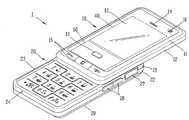
도 1은 본 발명과 관련된 휴대 단말기를 전면에서 바라본 것을 도시한 전면 사시도이다. 도 1에서 보는 것과 같이, 휴대 단말기(1)는 제1단말기 바디(10)와, 제1단말기 바디(10)에 적어도 일 방향을 따라 슬라이딩 가능하게 구성된 제2단말기 바디(20)를 포함한다.1 is a front perspective view of the mobile terminal according to the present invention as viewed from the front. As shown in FIG. 1, the
제1단말기 바디(10)가 제2단말기 바디(20)와 중첩되게 배치된 상태를 닫힌 상태(closed configuration)라 칭할 수 있으며, 본 도면에 도시된 바와 같이 제1단말기 바디(10)가 제2단말기 바디(20)의 적어도 일 부분을 노출한 상태를 열린 상태(open configuration)라 칭할 수 있다.A state in which the
휴대 단말기(1)는 닫힌 상태에서 주로 대기 모드로 작동하지만 사용자의 조작에 의해 대기 모드가 해제되기도 한다. 그리고, 열린 상태에서 주로 통화 모드 등으로 작동하지만 사용자의 조작 또는 일정 시간의 경과에 의해 대기 모드로 전환되기도 한다.Although the
제1단말기 바디(10)의 외관을 이루는 케이스(케이싱, 하우징, 커버 등으로 불려질 수 있다)는 프론트 케이스(11)와 리어 케이스(12)에 의해 형성된다. 프론트 케이스(11)와 리어 케이스(12)에 의해 형성된 공간에는 각종 전자부품들이 내장된다. 프론트 케이스(11)와 리어 케이스(12) 사이에는 적어도 하나의 중간 케이스들이 추가로 배치될 수도 있다. 케이스들은 합성수지를 사출하여 형성되거나 금속 재질, 예를 들어 스테인레스 스틸(STS) 또는 티타늄(Ti) 등과 같은 금속 재질을 갖도록 형성될 수도 있다.A case (which may be called a casing, a housing, a cover, etc.) forming the exterior of the
제1단말기 바디(10)의 하단은 라운드 형태로 형성될 수 있으며, 라운드 형상으로 형성된 프론트 케이스(11)의 하단에는 두 개, 세 개 또는 그 이상의 푸시버튼(15)이 구비되어 있다. 이러한 푸시버튼(15)은 통화키 또는 종료나 전원의 온오프 등 또는 특정 기능을 바로 실행 등으로 배정될 수 있다. 푸시버튼(15)은 눌려지지 않았을 때 프론트 케이스(11)의 외곽선에 부합되는 형상으로 형성됨으로써, 전 체적으로 휴대 단말기(1)의 통일화된 이미지를 구현하도록 하는 것이 바람직하다.The lower end of the first
하단의 푸시버튼(15)를 제외하고는, 제1단말기 바디(10)의 전면은 장대화된 윈도우(13)에 의하여 덮고 있다. 윈도우(13) 및 윈도우(13)의 내측에는 디스플레이를 위한 제1영역(40)과 터치방식으로 키입력을 위한 제2영역(50)이 포함되어 있다. 즉, 제1영역(40)은 휴대 단말기(1)가 갖는 다양한 모드에 따른 시각정보를 출력할 수 있게 되어 있으며, 제2영역(50)은 몇 가지의 키를 포함함으로써 그 키에 대해 터치가 있으면 해당 기능을 실행하거나 입력을 할 수 있게 구성된다.Except for the
도 2에 의하면, 윈도우(13)는 일체형으로 형성되어 있다. 윈도우(13)의 표면은 내측의 서로 다른 기능을 갖는 제1영역(40)과 제2영역(50)을 포함하고 있으면서도 제1영역(40)과 제2영역(50)을 구획하는 조립틈이나 경계형상을 두지 않는 매끄러운 형태로 형성되는 것이 가능하다. 이러한 윈도우(13)는 장대화되는 경우 변형에 취약할 수 있으므로 강화유리와 같은 재질로 형성되는 것이 바람직하다.According to FIG. 2, the
윈도우(13) 상에는 음향출력부(14), 제1영상입력부(16) 및 대략 제1영역(50)의 중앙에 배치되는 푸시버튼(51)이 구비되어 있다.The
제1영상입력부(16)는 제1단말기 바디(10) 전면의 외관을 해하지 않도록 윈도우(13)의 내부에 배치되며, 제1영상입력부(16)에 대응되는 윈도우(13)의 일정 면적은 피사체의 광이 통과될 수 있도록 투광성으로 형성된다. 제1영상입력부(16)는 사용자 등에 대한 이미지 또는 동영상을 촬영하기 위한 카메라 모듈과 같은 형태로 구현될 수 있다.The first
제1음향출력부(14)는 윈도우(13)에 관통되게 형성되는 사운드홀(13a: 도 3 참조)의 내부에 배치되며, 통화음 뿐만 아니라 시스템의 각종 알림음 또는 멀티미디어의 재생음 등을 출력할 수 있다. 제1음향출력부(14)는 스테레오 기능을 구현할 수 있도록 복수 개로 구비될 수 있다.The first
윈도우(13)의 제1영역(40)은 내부에 배치되는 디스플레이 모듈(41: 도 3 참조)에서 출력되는 화면이 보일 수 있도록 투광성 또는 반투광성으로 형성될 수 있으며, 제1영역(40)을 제외한 나머지 영역은 불투광성으로 형성될 수 있다.The
윈도우(13)의 제2영역(50)은 각 키에 대한 표지(symbol 또는 mark)가 형성될 수 있다. 각 표지는 윈도우(13)의 내측면에 네거티브 방식으로 인쇄됨으로써, 대기상태에서는 명확하지 않다가 터치가 있는 경우 윈도우(13)의 내부에 배치되는 조명유닛(53: 도 3 참조)의 도움에 의하여 명확히 식별될 수 있도록 형성될 수 있다. 다른 예로서, 표지는 복수의 세트로 구성됨으로써 휴대 단말기(1)의 모드에 따라 조명유닛(53)에 의하여 서로 다른 세트의 표지가 보이도록 구성되는 것도 가능하다.In the
제2영역(50)의 가운데에 배치되는 푸시버튼(51)은 여러 개로 나뉘어져 배치되어 있는 키의 위치를 파악하는데 기준점을 제공할 수 있다. 즉, 푸시버튼(51)을 제외한 나머지 키들은 터치 방식으로 동작되므로 키의 위치를 용이하게 파악하기 어려울 수 있다. 푸시버튼(51)은 윈도우(13)로부터 일정 높이로 돌출된 형상으로 형성되어 쉽게 구별할 수 있으므로, 푸시버튼(51)을 중심으로 그 주위에 배치되는 터치방식의 키를 정확하게 조작시킬 수 있게 된다.The
제1단말기 바디(10)와 마찬가지로, 제2단말기 바디(20)도 프론트 케이스(21) 와 리어 케이스(22)를 포함할 수 있다.Like the first
제2단말기 바디(20), 구체적으로 프론트 케이스(21)의 전면(front face)에는 키패드(23)가 배치될 수 있으며, 프론트 케이스(21) 또는 리어 케이스(22) 중 적어도 하나에는 사이드키(26), 음향입력부(24), 외부 인터페이스(27)가 배치될 수 있다.The
제2영역(50)의 푸시버튼(51)과 터치키, 제1단말기 바디(10)의 하단의 푸시버튼(15), 제2단말기 바디(20)의 키패드(23) 및 사이트키(26)는 조작부(manipulating portion)라 통칭될 수 있다. 이들 조작부 외에도 키를 회전시키는 휠 또는 조그 방식이나 조이스틱과 같이 조작하는 방식 등으로도 구현될 수 있는 입력수단을 추가적으로 가질 수 있다. 기능적인 면에서, 제1단말기 바디(10)의 터치키나 푸시버튼(15,51)은 시작, 종료, 스크롤 등과 같은 명령을 입력하기 위한 것이고, 키패드(23)는 숫자 또는 문자, 심볼(symbol) 등을 입력하기 위한 것이다. 또한, 사이드키(26)는 제1영상입력부(16)의 활성화 등과 같은 특수한 기능을 수행하는 핫 키(hot-key)로서 작동할 수 있다.
음향입력부(24)는 사용자의 음성, 기타 소리 등을 입력받기 위해, 예를 들어 마이크로폰(Microphone)과 같은 형태로 구현될 수 있다.The
외부 인터페이스(27)는 본 발명과 관련된 휴대 단말기(1)가 외부 기기와 데이터 교환 등을 할 수 있게 하는 통로가 된다.The
예를 들어, 외부 인터페이스(26)는 유선 또는 무선으로, 이어폰과 연결하기 위한 접속단자 또는 근거리 통신을 위한 포트{예를 들어 적외선 포트(IrDA port), 블루투스 포트(Bluetooth port), 무선 랜 포트(wireless Lan port)등}에 전원을 공급하기 위한 전원공급 단자들 중 적어도 하나일 수 있다. 예를 들어, 외부 인터페이스(27)는 유선 또는 무선으로, 이어폰과 연결하기 위한 접속단자, 적외선 포트(IrDA port), 무선 랜 포트(wireless Lan port) 중 적어도 하나일 수 있다. 그리고, 외부 인터페이스(27)는 SIM(subscriber identification module) 또는 UIM(user identity module), 정보 저장을 위한 메모리 카드 등의 외장형 카드를 수용하는 카드 소켓일 수도 있다.For example, the
리어 케이스(22) 측에는 휴대 단말기(1)에 전원을 공급하기 위한 배터리를 덮기 위한 배터리커버(29)가 착탈 가능하게 설치될 수 있다. 배터리는 계속적으로 사용할 수 있도록 충전 가능하며, 본 실시예와 달리 외장의 형태로 착탈 가능하게 결합될 수도 있다.On the
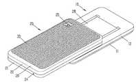
도 2는 도 1의 휴대 단말기의 후면 사시도이다. 도 2를 참조하면, 제2단말기 바디(20)의 배터리커버(29)의 후면에는 제2영상입력부(25)가 추가로 장착될 수 있다. 제2영상입력부(25)는 제1영상입력부(16)와 실질적으로 반대되는 촬영 방향을 가지며, 제1영상입력부(16)와 서로 다른 화소를 가지는 카메라일 수 있다. 예를 들어, 제1영상입력부(16)는 화상 통화 등의 경우에 사용자의 얼굴을 촬영하여 상대방에 전송함에 무리가 없도록 저화소를 가지며, 제2영상입력부(25)는 일반적인 피사체를 촬영하고 바로 전송하지는 않는 경우가 많기에 고화소를 가지는 것이 바람직하다. 제2영상입력부(25)에 인접하게는 플래쉬와 거울부가 추가로 배치될 수 있다.2 is a rear perspective view of the portable terminal of FIG. 1. Referring to FIG. 2, a second
제1단말기 바디(10)의 리어 케이스(12) 측에는 제1단말기 바디(10)와 제2단 말기 바디(20)를 슬라이딩 가능하게 결합하는 슬라이드 모듈(28)의 일 부분이 배치된다. 슬라이드 모듈(28)의 다른 부분은 제2단말기 바디(20)의 프론트 케이스(21) 측에 배치되어, 본 도면에서와 같이 외부로 드러나지 않는 형태일 수 있다.A portion of the
배터리커버(29)는 제2단말기 바디(20)의 후면을 모두 덮는 형태로 형성됨으로써 후면에 다름 부품과의 조립틈이나 경계선을 만들지 않도록 하는 것이 가능하다. 배터리커버(29)의 후면에는 휴대 단말기(1)가 바닥이나 경사면에 대하여 쉽게 이동되어 낙하되는 것을 방지하기 위한 패턴부(30)가 형성될 수 있다. 패턴부(30)는 격자 또는 빗살무늬와 같은 기하학적인 규칙적인 무늬를 포함할 수 있다. 이와 같은 패턴부(30)는 수지물을 메탈 베이스에 코팅 또는 사출함으로써 형성할 수 있다.The
도 1과 도 2에서는 제2영상입력부(25) 등이 제2단말기 바디(20)에 배치되는 것으로 설명하였으나, 반드시 그에 제한되는 것은 아니다. 예를 들어, 제2영상입력부(25) 등과 같이 배터리커버(29)에 배치되는 것으로 설명한 구성들 중 적어도 하나 이상이 제1단말기 바디(10), 주로는 리어 케이스(12)에 장착되는 것도 가능하다. 그러한 경우라면, 닫힌 상태에서 리어 케이스(12)에 배치되는 구성(들)이 제2단말기 바디(20)에 의해 보호되는 이점이 있다. 나아가, 제2영상입력부(25)가 별도로 구비되지 않더라도, 제1영상입력부(16)가 회전 가능하게 형성되어 제2영상입력부(25)의 촬영 방향까지 촬영이 가능하도록 구성될 수도 있다.In FIG. 1 and FIG. 2, the second
본 발명의 일예에 관련된 휴대 단말기는 도 1 및 도 2에 도시된 슬라이드 타입에 한정되는 것이 아니고, 바 타입, 폴더 타입 또는 스윙 타입 등 다양한 구조에 도 적용이 가능하다.The portable terminal according to an embodiment of the present invention is not limited to the slide type shown in FIGS. 1 and 2, but may be applied to various structures such as a bar type, a folder type, or a swing type.
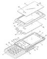
도 3은 도 1의 휴대 단말기의 분해 사시도이다. 도 3에서 보는 것과 같이, 제1단말기 바디(10)는 윈도우(13), 프론트 케이스(11), 터치시트(60) 및 디스플레이 모듈(41)과 회로기판(52)을 포함할 수 있다.3 is an exploded perspective view of the portable terminal of FIG. 1. As shown in FIG. 3, the first
윈도우(13)의 제2영역(50)에는 도 1에서 설명한 푸시버튼(51)이 통과될 수 있도록 관통홀(13a)이 형성되어 있으며, 이에 대응하여 터치시트(60)의 제2영역(50)에도 관통홀(61)이 형성된다.A through
터치시트(60)의 하단은 푸시버튼(15)이 통과될 수 있도록 복수의 관통홀(62)이 추가적으로 형성됨으로써 회로기판(52) 상에 형성되어 있는 돔스위치(55)를 작동시킬 수 있다. 돔스위치(55)의 일측에는 푸시버튼(15)을 조명시키는 엘이디(54)가 장착될 수 있다.The lower end of the
터치시트(60)의 하단은 플렉시블 피시비(Flexible PCB)에 의하여 회로기판(52) 또는 제1단말기 바디(10)에 연결될 수 있다.The lower end of the
회로기판(52)에는 위에서 설명한 관통홀(61)을 통과하며 푸시방식으로 입력하는 푸시버튼(51)이 설치된다.The
제2영역(50)을 조명시키도록 푸시버튼(51)의 주위에는 조명유닛(53)이 설치될 수 있다. 바람직하게는 조명유닛(53)은 면발광하는 이엘시트(EL Sheet)와 같은 발광소자로 형성될 수 있다. 나아가, 조명유닛(53)은 터치되는 키를 개별적으로 조명하면서도 조명시간, 조명면적을 달리 제어함으로써 다양한 조명효과를 구현할 수 있게 구성될 수 있다. 예를 들어, 제2영역(50)에 대한 터치가 있는 경우, 그 터치 된 부위를 중심으로 밝은 부위가 반경방향으로 순차적으로 이동되도록 구성될 수 있다.An
도 4는 본 발명과 관련된 터치시트의 평면도이다. 도 4에 의하면, 터치시트(60)는 제1영역(40)에 가해진 터치를 감지하는 터치스크린패턴부(63)와, 제2영역(50)에 가해진 터치를 감지하는 터치버튼패턴부(65)를 포함하고 있다.4 is a plan view of a touch sheet according to the present invention. Referring to FIG. 4, the
터치스크린패턴부(63)는 터치된 위치를 계산할 수 있도록 가로 방향 및 세로방향으로 형성되는 복수의 도전성 라인을 포함한다. 터치시트(60)의 가장자리에는 터치스크린패턴부(63)에 연결되어 신호를 전송하는 데이터라인(66)이 형성된다. 다만, 터치스크린패턴부(63)는 도 4의 예시와 다른 패턴을 형성하는 것도 가능하다. 예를 들어 하나의 도전성 라인이 지그재그 형태로 형성될 수 있다. 이 경우, 하나의 레이어로 터치시트가 형성되므로 전체적인 두께는 감소되는 이점이 있다.The touch
터치스크린패턴부(63)의 형상에 반하여, 터치버튼패턴부(65)는 상의 복수의 개소에 일정 면적을 갖도록 배치되고 있다. 도 4에 의하면, 터치버튼패턴부(65)는 푸시버튼(51)이 통과되는 관통홀(61)의 주위의 상·하·좌·우 네 곳에 각각 나뉘어져 배치되고 있다. 이 경우, 각 터치버튼패턴부(61)는 커서나 포인터의 방향을 이동시킬 수 있게 배정됨으로써, 디스플레이 모듈(41)에 의하여 출력되는 복수의 항목에 대한 이동이나 탐색을 용이하게 할 수 있다. 각 터치버튼패턴부(65)는 복수의 키값(key value)를 가질 수 있다.Contrary to the shape of the touch
각 터치버튼패턴부(65)는 각각의 데이터라인(65a)에 의하여 연결되어 있으며, 각 데이터라인(65a)은 플렉시블 피시비(70)에 연결되기 위해 각별로 형성되어 있다. 이에 따라 임의의 터치버튼패턴부(65)에 대하여 터치가 있으면 해당 터치버튼패턴부(65)에 의하여 감지된다. 터치버튼패턴부(65)는 윈도우(13)에 가해진 터치에 의하여 발생되는 정전용량(capacitance)의 변화를 감지하여 이에 대한 전기적 신호를 전송한다. 이외에도, 터치버튼패턴부(65)에는 알려져 있는 정압방식 또는 저항막 방식이 적용될 수 있다.Each touch
이와 같이, 터치버튼패턴부(65)는 터치스크린패턴부(63)와 달리 상호 거리를 두고 떨어져 배치되어 있으며, 각 데이터라인(65a)은 서로 영향을 주지 않고 배치되고 있으므로, 터치버튼패턴부(65) 사이의 공간은 관통홀(61)과 같이 다른 용도로 사용되는 것이 가능하다. 따라서, 전면이 터치방식으로 입력되는 휴대 단말기에 클릭감을 제공하는 푸시버튼(51)의 설치를 가능하게 한다.As described above, the touch
도 4에 의하면, 터치스크린패턴부(63)의 데이터라인(67)은 터치시트(60)의 가장자리를 따라 배열되고 있으며, 터치버튼패턴부(65)의 데이터라인(65a)과 함께 플렉시블 피시비(70)에 연결될 수 있도록 플렉시블 피시비(70)에 연결되는 부분이 양 쪽에서 집합되어 있는 배치를 보이고 있다. 따라서, 플렉시블 피시비(40)가 제1영역(40)과 제2영역(50) 각각에 연결되지 않고, 어느 한 영역에서 집중적으로 연결되므로 다른 부품의 배치를 방해하지 않고 조립을 용이하게 한다.Referring to FIG. 4, the data lines 67 of the touch
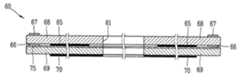
도 5는 도 4의 터치시트의 V-V선에 따른 단면도이며, 도 6은 VI-VI선에 따른 단면도이다.FIG. 5 is a cross-sectional view taken along line V-V of the touch sheet of FIG. 4, and FIG. 6 is a cross-sectional view taken along line VI-VI.
이들 도면에 도시된 것과 같이, 터치시트(60)는 터치스크린패턴부(63)와 터치버튼패턴부(65)가 형성된 투광성 절연층(68,69)을 포함한다. 투광성 절연 층(68,69)은 폴리에틸렌 필름으로 형성될 수 있으며, 여러 장이 적층된 형태로 형성될 수 있다.As shown in these figures, the
도 5에 의하면, 터치시트(60)의 제2영역(50)은 내측면에 터치버튼패턴부(65)가 형성된 제1투광성 절연층(68)과 제1투광성 절연층의 하부에 전체면이 도전막(70)으로 형성되는 제2투광성 절연층(69)으로 이루어진다. 제1투광성 절연층(68)과 제2투광성 절연층(69)은 접착제층(75)에 의하여 상호 접착되어 있다. 제2투광성 절연층(69)에 형성되는 도전막(70)은 내부의 부품에 의한 전기장의 영향을 차단하는 역할을 할 수 있다.Referring to FIG. 5, the
터치버튼패턴부(65)는 내부의 조명유닛(53)의 빛이 통과될 수 있도록 투광성 또는 반투광성 재질로 형성된다. 바람직하게는, 터치스크린패턴부(63)와 터치버튼패턴부(65)는 ITO(Indum Tin Oxide)가 스퍼터링(sputtering)됨으로써 형성될 수 있다.The touch
제1투광성 절연층(68)의 가장자리에는 터치스크린패턴부(63)의 데이터라인(66)을 쉴딩하는 도전성의 쉴딩라인(67)이 형성된다. 아울러, 쉴딩라인(67)은 터치스크린패턴부(63)의 데이터라인(66)이 제1영역(40)으로 내려오는 동안에도 쉴딩을 할 수 있도록 제1영역(40)으로 연장된 형태로 형성될 수 있다(도 4 및 도 5 참조).A
도 4에 의하면, 쉴딩라인(67)은 터치스크린패턴부(63)가 형성된 제1영역(40)과 터치버튼패턴부(65)가 형성된 제2영역(50)을 구획한다. 터치스크린패턴부(63)의 데이터라인(66) 또는 쉴딩라인(68)은 터치스크린패턴부(63) 및 터치버튼패턴부(65) 와 달리 동박이나 도전성 메탈이 프린팅되어 형성됨으로써 제조비용을 절감시킬 수 있다.Referring to FIG. 4, the shielding
도 5에 의하면, 쉴딩라인(67)은 터치스크린패턴부(63)의 데이터라인(66)이 배치된 제1투광성 절연층(68)의 반대면에 위치됨으로써 쉴딩라인(67)이 차지하는 면적을 줄이면서도 쉴딩효과를 높일 수 있다.Referring to FIG. 5, the shielding
바람직하게는 쉴딩라인(67)은 조명유닛(53)의 그라운드와 전기적으로 단락시킴으로써 보다 정밀한 터치를 감지하는 터치스크린패턴부(63)가 조명유닛(53)에 의하여 영향을 받아 오작동되는 것을 방지할 수 있다.Preferably, the shielding
도 6에서 보는 것과 같이, 터치스크린패턴부(63)는 가로패턴부(63A)과 세로패턴부(63B)의 조합에 의하여 이루어지며, 가로패턴부(63A)가 형성된 투광성 절연층(68A)과 세로패턴부(63B)가 형성된 투광성 절연층(68B) 및 도전막(70)이 형성된 투광성 절연층(69)을 포함하고 있다. 따라서, 윈도우(13)의 제1영역(40)에 가해진 터치는 가로패턴부(63A)와 세로패턴부(63B)의 정전용량 등의 변화로 감지되고, 해당되는 가로패턴부(63A)와 세로패턴부(63B)의 위치의 조합에 의하여 터치된 위치에 대응하는 입력작용이 이루어지게 된다.As shown in FIG. 6, the touch
가로패턴부(63A)와 세로패턴부(63B)는 상호 위치의 교환이 가능하다. 아울러, 가로패턴부(63A)와 세로패턴부 또한 터치버튼패턴부(65)와 동일하게 ITO(Indum Tin Oxide)가 스퍼터링(sputtering)됨으로써 형성될 수 있다.The
도 7은 본 발명과 관련된 휴대 단말기의 블록 구성도이다.7 is a block diagram of a portable terminal according to the present invention.
도시된 본 발명의 일 예는 무선통신 모듈(81), 조작부(15,26,60), 영상입력 부(16,25), 음향 입력부(24), 디스플레이 모듈(41), 음향 출력부(14), 외부 인터페이스(27), 방송수신 모듈(86), 메모리(84), 전원 공급부(87), 제어부(80) 등을 포함하여 이루어진다.An example of the present invention shown is the
조작부(15,26,60)는 도 1내지 도 4에 도시된 바와 같이 구성되어 사용자가 단말기의 동작 제어를 위하여 입력하는 입력 데이터를 제어부(80)에 제공한다.The
제어부(80)는 휴대 단말기의 전반적인 동작을 제어한다. 예를 들어 음성 통화, 데이터 통신, 화상 통화 등을 위한 관련된 제어 및 처리를 수행한다. 또한, 제어부(80)는 통상적인 기능 제어 이외에 터치시트(60)로부터 전달된 터치신호를 받아 그 입력신호에 따른 제어명령을 실행한다.The
무선통신 모듈(81)은 안테나를 통하여 이동통신 기지국과 무선 신호를 송/수신한다. 예를 들어 제어부(80)의 제어 하에 음성 데이터, 문자 데이터, 영상 데이터 및 제어 데이터의 송수신을 담당하며 이를 위해 송신할 신호를 변조하여 송신하는 송신부(83)와, 수신되는 신호를 복조하는 수신부(82)를 포함한다.The
영상입력부(16,25)는 사용자 등에 대한 이미지 또는 동영상을 촬영하기 위한 카메라 모듈과 같은 형태로 구현될 수 있다. 영상입력부(16,25)가 사용되는 모드 즉, 촬영이나 화상통화 모드에 있는 경우, 디스플레이 모듈(41)은 제어부(80)의 제어에 의해 영상입력부(16,25)의 각종 기능을 제어하기 위한 표지들을 표시한다.The
영상입력부(16,25)는 이미지 센서에 의해 얻어지는 정지영상 또는 동영상 등의 화상 프레임을 처리한다. 처리된 화상 프레임은 디스플레이 모듈(41)에 표시 가능한 영상 데이터로 변환되어 디스플레이 모듈(41)로 출력된다. 영상입력부(16,25) 에서 처리된 화상 프레임은 제어부(80)의 제어에 의해 메모리(84)에 저장되거나 무선 통신모듈(81)을 통하여 외부로 전송된다.The
음향 입력부(24)는 통화모드 또는 녹음모드, 음성인식 모드 등에서 마이크로폰(Microphone)에 의해 외부의 음향 신호를 입력받아 전기적인 음성 데이터로 처리한다. 그리고, 처리된 음성 데이터는 통화 모드인 경우 무선통신 모듈(81)를 통하여 이동통신 기지국으로 송신 가능한 형태로 변환되어 무선통신 모듈(81)로 출력된다. 녹음 모드인 경우 처리된 음성 데이터는 메모리(84)에 저장되도록 출력된다.The
음향 입력부(24)는 외부의 음향 신호를 입력받는 과정에서 발생되는 잡음(noise)를 제거하기 위한 다양한 잡음 제거 알고리즘이 구현될 수 있다.The
디스플레이 모듈(41)은 휴대 단말기에서 처리되는 정보를 표시 출력한다. 예를 들어 휴대 단말기가 통화 모드인 경우 제어부(80)의 제어에 의해 통화와 관련된 UI(User Interface) 또는 GUI(Graphic User Interface)를 표시 출력한다. 그리고 휴대 단말기가 화상통화 모드 또는 촬영 모드인 경우 제어부(80)의 제어에 의해 촬영된 영상 또는 UI,GUI를 표시 출력한다.The
디스플레이 모듈(41)에 의하여 출력되는 내용은 터치시트(60)의 터치스크린패턴부(63)에 의하여 입력가능한 항목이나 리스트일 수 있다.The content output by the
음향 출력부(14)는 호신호 수신, 통화모드 또는 녹음 모드, 음성인식 모드, 방송수신 모드 등에서 제어부(80)의 제어에 의해 무선통신 모듈(81)로부터 수신된 음향 데이터 또는 메모리(84)에 저장된 음향 데이터를 변환하여 외부로 출력한다. 또한, 음향 출력부(14)는 휴대 단말기에서 수행되는 기능(예를 들어, 호신호 수신 음, 메시지 수신음 등)과 관련된 음향 신호를 출력한다. 이러한 음향 출력부(14)는 스피커(speaker), 리시버(Receiver), 버저(Buzzer) 등으로 포함한다.The
외부 인터페이스(27)는 휴대 단말기 이외 유/무선 헤드셋, 외부 충전기, 유/무선 데이터 포트, 카드 소켓(예를 들어, 메모리 카드(Memory card), SIM/UIM card) 등을 휴대 단말기에 연결되는 모든 외부기기와의 인터페이스 역할을 한다. 이와 같은 외부 인터페이스(27)는 외부 기기로부터 데이터를 전송받거나 전원을 공급받아 휴대 단말기 내부의 각 구성 요소에 전달하거나 휴대 단말기 내부의 데이터가 외부 기기로 전송되도록 한다.The
메모리(84)는 제어부(80)의 처리 및 제어를 위한 프로그램이 저장될 수도 있고, 입/출력되는 데이터들(예를 들어, 폰북, 메시지, 정지영상, 동영상 등)의 임시 저장을 위한 기능을 수행할 수도 있다. 이러한 메모리(84)는 일반적으로 알려진 하드 디스크, 카드 타입의 메모리(예를 들어 SD 또는 XD 메모리 등), 플래시 메모리, 램, 롬 등의 개념을 포함한다.The
센싱 유닛(85)은 휴대 단말기의 개폐 상태, 휴대 단말기의 위치, 사용자 접촉 유무 등과 같이 휴대 단말기의 현 상태를 감지하여 휴대 단말기의 동작을 제어하기 위한 센싱 신호를 발생시킨다. 예를 들어 휴대 단말기가 슬라이드 폰 형태인 경우 슬라이드 폰의 개폐 여부를 센싱하여 제어부(80)로 센싱 결과를 출력하여 단말기의 동작이 제어되도록 한다. 또한 전원 공급부(87)의 전원 공급 여부, 외부 인터페이스(27)의 외부 기기 결합 여부 등과 관련된 센싱 기능을 담당한다.The
방송수신 모듈(86)은 위성 또는 지상파 등을 통하여 전송된 방송 신호를 수 신하여 음향 출력부(14), 디스플레이 모듈(41)에 출력 가능한 방송 데이터 형태로 변환하여 제어부(80)에 출력한다. 또한 방송수신 모듈(86)은 방송과 관련된 부가 데이터(예를 들면, EPG(Electric Program Guide), 채널 리스트 등)를 수신한다. 방송수신 모듈(86)에서 변환된 방송 데이터 및 부가 데이터는 메모리(84)에 저장될 수도 있다.The
상기와 같이 설명된 휴대 단말기는 상기 설명된 실시예들의 구성과 방법이 한정되게 적용될 수 있는 것이 아니라, 상기 실시예들은 다양한 변형이 이루어질 수 있도록 각 실시예들의 전부 또는 일부가 선택적으로 조합되어 구성될 수도 있다.The above-described portable terminal is not limited to the configuration and method of the above-described embodiments, but the embodiments may be configured by selectively combining all or some of the embodiments so that various modifications can be made. It may be.
도 1은 본 발명과 관련된 휴대 단말기의 일 예를 전면에서 바라본 사시도1 is a front perspective view of an example of a mobile terminal according to the present invention;
도 2는 도 1의 휴대 단말기의 후면 사시도2 is a rear perspective view of the mobile terminal of FIG.
도 3은 도 1의 휴대 단말기의 분해 사시도3 is an exploded perspective view of the portable terminal of FIG. 1;
도 4는 터치시트의 평면도4 is a plan view of a touch sheet
도 5는 도 4의 V-V선에 따른 단면도5 is a cross-sectional view taken along the line V-V of FIG.
도 6은 도 4의 VI-VI선에 따른 단면도6 is a cross-sectional view taken along the line VI-VI of FIG.
도 7은 본 발명과 관련된 휴대 단말기의 블록 다이어그램7 is a block diagram of a mobile terminal related to the present invention.
Claims (18)
Translated fromKoreanPriority Applications (14)
| Application Number | Priority Date | Filing Date | Title |
|---|---|---|---|
| KR1020070114420AKR100904960B1 (en) | 2007-11-09 | 2007-11-09 | Handheld terminal |
| DE602008002984TDE602008002984D1 (en) | 2007-11-09 | 2008-02-18 | Mobile terminal |
| AT08101720TATE484788T1 (en) | 2007-11-09 | 2008-02-18 | MOBILE DEVICE |
| EP08101720AEP2058729B1 (en) | 2007-11-09 | 2008-02-18 | Mobile terminal |
| ES08101720TES2354132T3 (en) | 2007-11-09 | 2008-02-18 | MOBILE TERMINAL |
| PT08101720TPT2058729E (en) | 2007-11-09 | 2008-02-18 | Mobile terminal |
| TW097123355ATWI387906B (en) | 2007-11-09 | 2008-06-23 | Mobile terminal |
| US12/163,992US9462097B2 (en) | 2007-11-09 | 2008-06-27 | Mobile terminal |
| RU2008128215/09ARU2399085C2 (en) | 2007-11-09 | 2008-07-09 | Mobile terminal |
| BRPI0803740-0ABRPI0803740B1 (en) | 2007-11-09 | 2008-07-15 | MOBILE TERMINAL |
| CN2008101339794ACN101431563B (en) | 2007-11-09 | 2008-07-16 | Mobile terminal |
| JP2008215890AJP5149103B2 (en) | 2007-11-09 | 2008-08-25 | Portable terminal |
| US15/085,136US9456062B2 (en) | 2007-11-09 | 2016-03-30 | Mobile terminal |
| US15/261,510US9880690B2 (en) | 2007-11-09 | 2016-09-09 | Mobile terminal |
Applications Claiming Priority (1)
| Application Number | Priority Date | Filing Date | Title |
|---|---|---|---|
| KR1020070114420AKR100904960B1 (en) | 2007-11-09 | 2007-11-09 | Handheld terminal |
Publications (1)
| Publication Number | Publication Date |
|---|---|
| KR100904960B1true KR100904960B1 (en) | 2009-06-26 |
Family
ID=40282349
Family Applications (1)
| Application Number | Title | Priority Date | Filing Date |
|---|---|---|---|
| KR1020070114420AActiveKR100904960B1 (en) | 2007-11-09 | 2007-11-09 | Handheld terminal |
Country Status (12)
| Country | Link |
|---|---|
| US (3) | US9462097B2 (en) |
| EP (1) | EP2058729B1 (en) |
| JP (1) | JP5149103B2 (en) |
| KR (1) | KR100904960B1 (en) |
| CN (1) | CN101431563B (en) |
| AT (1) | ATE484788T1 (en) |
| BR (1) | BRPI0803740B1 (en) |
| DE (1) | DE602008002984D1 (en) |
| ES (1) | ES2354132T3 (en) |
| PT (1) | PT2058729E (en) |
| RU (1) | RU2399085C2 (en) |
| TW (1) | TWI387906B (en) |
Cited By (5)
| Publication number | Priority date | Publication date | Assignee | Title |
|---|---|---|---|---|
| KR101104931B1 (en) | 2010-02-24 | 2012-01-12 | 주식회사 토비스 | Resistive touch panel, system including the same and touch input receiving method |
| KR101104930B1 (en) | 2010-02-24 | 2012-01-12 | 주식회사 토비스 | Resistive touch panel, system including the same and touch input receiving method |
| KR101164095B1 (en) | 2010-12-20 | 2012-07-12 | 엘지이노텍 주식회사 | Touch window and portable terminal therewith |
| KR101303633B1 (en)* | 2011-06-13 | 2013-09-11 | 엘지이노텍 주식회사 | Self-Capacitance Touch window |
| KR20130120766A (en)* | 2012-04-26 | 2013-11-05 | 엘지이노텍 주식회사 | Touch panel and manufacturing method thereof |
Families Citing this family (55)
| Publication number | Priority date | Publication date | Assignee | Title |
|---|---|---|---|---|
| KR100904960B1 (en) | 2007-11-09 | 2009-06-26 | 엘지전자 주식회사 | Handheld terminal |
| CN101634917B (en)* | 2008-07-21 | 2013-04-24 | 智点科技(深圳)有限公司 | Touch flat-panel display |
| JP5510451B2 (en)* | 2009-04-28 | 2014-06-04 | 日本電気株式会社 | Touch panel, touch panel manufacturing method, and electronic device |
| TWI460623B (en)* | 2009-07-14 | 2014-11-11 | Htc Corp | Touch-controlled electronic apparatus and related control method |
| CN201440650U (en)* | 2009-08-26 | 2010-04-21 | 珠海格力电器股份有限公司 | Touch control device |
| KR101649626B1 (en)* | 2009-08-27 | 2016-08-19 | 엘지전자 주식회사 | Mobile terminal |
| KR101631952B1 (en)* | 2010-01-06 | 2016-06-20 | 엘지전자 주식회사 | Mobile terminal |
| FR2956514B1 (en)* | 2010-02-12 | 2012-09-21 | Sagem Wireless | PORTABLE TELEPHONE HAVING A MARKING |
| KR101109313B1 (en)* | 2010-04-14 | 2012-01-31 | 삼성전기주식회사 | Display device including touch screen panel |
| KR101129724B1 (en)* | 2010-04-26 | 2012-03-28 | 크루셜텍 (주) | Processing device for touch and pointing signal and electronic device having that |
| KR101148685B1 (en)* | 2010-07-14 | 2012-05-23 | 삼성전기주식회사 | Touch Screen |
| USD663297S1 (en)* | 2010-08-09 | 2012-07-10 | Research In Motion Limited | Back housing for a handheld electronic device |
| USD655287S1 (en)* | 2010-08-13 | 2012-03-06 | Research In Motion Limited | Back housing for a handheld electronic device |
| JP5720293B2 (en)* | 2011-02-18 | 2015-05-20 | 日本精機株式会社 | Display device |
| EP2691912B1 (en)* | 2011-03-30 | 2015-05-20 | Giesecke & Devrient GmbH | Method for a data storage medium to interact with a terminal |
| CN102308268A (en)* | 2011-07-01 | 2012-01-04 | 华为终端有限公司 | A terminal and a manufacturing method of the terminal touch screen |
| WO2012149806A1 (en) | 2011-10-20 | 2012-11-08 | Huawei Technologies Co., Ltd. | Mobile terminal comprising lid unit with key device |
| KR101265650B1 (en)* | 2011-12-01 | 2013-05-22 | 엘지전자 주식회사 | Lighting apparatus and method of controlling the lighting apparatus using a remote controller |
| TWI490744B (en) | 2011-12-23 | 2015-07-01 | Lg Chemical Ltd | Touch panel and display apparatus comprising the same |
| CN103176641A (en)* | 2011-12-25 | 2013-06-26 | 宸鸿科技(厦门)有限公司 | Touch panel and manufacturing method thereof |
| CN102830844A (en) | 2012-08-17 | 2012-12-19 | 北京小米科技有限责任公司 | Touch screen misoperation prevention method, touch screen and mobile terminal |
| US9058941B2 (en)* | 2012-08-20 | 2015-06-16 | Apple Inc. | Floating switch assemblies and methods for making the same |
| US9030839B2 (en)* | 2012-10-18 | 2015-05-12 | Apple Inc. | Track pad acoustic features related to a portable computer |
| TWI489337B (en) | 2012-11-23 | 2015-06-21 | 義隆電子股份有限公司 | Method of manufacturing virtual function button of a touch panel, method of identifying interference and the touch panel |
| USD732040S1 (en) | 2013-01-29 | 2015-06-16 | Htc Corporation | Touch module for an electronic device |
| US9354738B2 (en) | 2013-02-07 | 2016-05-31 | Htc Corporation | Touch panel assembly and electronic apparatus |
| JP6119518B2 (en) | 2013-02-12 | 2017-04-26 | ソニー株式会社 | Sensor device, input device and electronic apparatus |
| TWI492163B (en)* | 2013-02-20 | 2015-07-11 | Smartdisplayer Technology Co Ltd | Electronic card and its capacitive touch sensing method |
| JP6288073B2 (en) | 2013-03-18 | 2018-03-07 | ソニー株式会社 | Sensor device, input device and electronic device |
| JP6311129B2 (en)* | 2013-04-24 | 2018-04-18 | パナソニックIpマネジメント株式会社 | Touch panel |
| KR102069808B1 (en) | 2013-05-16 | 2020-02-12 | 삼성디스플레이 주식회사 | Organic light emitting display panel |
| JP6142745B2 (en)* | 2013-09-10 | 2017-06-07 | ソニー株式会社 | Sensor device, input device and electronic apparatus |
| CN103576987A (en)* | 2013-10-18 | 2014-02-12 | 小米科技有限责任公司 | ITO thin film and terminal equipment |
| KR102168132B1 (en) | 2013-12-31 | 2020-10-21 | 삼성디스플레이 주식회사 | Organic light emitting device |
| CN104331182B (en)* | 2014-03-06 | 2017-08-25 | 广州三星通信技术研究有限公司 | Portable terminal with auxiliary touch-screen |
| JP2015190859A (en) | 2014-03-28 | 2015-11-02 | ソニー株式会社 | Sensor device, input device, and electronic apparatus |
| US20150346863A1 (en)* | 2014-05-29 | 2015-12-03 | Kabushiki Kaisha Toshiba | Touch panel and electronic device with touch panel |
| US20190045620A1 (en)* | 2014-07-09 | 2019-02-07 | Schreiner Group Gmbh & Co. Kg | Sensor device with a flexible electrical conductor structure |
| AU2014405473B2 (en) | 2014-09-03 | 2018-05-24 | Honor Device Co., Ltd. | Terminal, touch control unit, touchscreen, screen protector, and operation detection apparatus and method |
| JP5944974B2 (en)* | 2014-12-02 | 2016-07-05 | 京セラ株式会社 | Portable terminal and input control program |
| KR101847075B1 (en)* | 2014-12-18 | 2018-04-09 | 삼성전자주식회사 | Electronic device |
| USD819742S1 (en)* | 2015-03-04 | 2018-06-05 | Americhip, Inc | Vertical digital video blade |
| USD819741S1 (en)* | 2015-03-04 | 2018-06-05 | Americhip, Inc. | Horizontal digital video blade |
| USD819743S1 (en)* | 2015-03-04 | 2018-06-05 | Americhip, Inc. | Vertical digital video blade |
| USD791236S1 (en)* | 2015-03-04 | 2017-07-04 | Americhip, Inc. | Digital video blade |
| RU2701165C2 (en)* | 2015-06-04 | 2019-09-25 | Хуавэй Текнолоджиз Ко., Лтд. | Mobile terminal and heat-removing and screening structure |
| JP2019079081A (en)* | 2016-03-11 | 2019-05-23 | アルプスアルパイン株式会社 | Capacitive sensor |
| KR101841583B1 (en) | 2016-12-05 | 2018-03-26 | 삼성전자주식회사 | Mounting structure for a module in an electronic device |
| CN107065265A (en)* | 2017-05-05 | 2017-08-18 | 广东欧珀移动通信有限公司 | Display device and mobile electronic terminal |
| CN116540891A (en)* | 2017-08-01 | 2023-08-04 | 株式会社和冠 | Sensor for detecting pen signal sent by pen |
| US10691176B2 (en)* | 2018-07-12 | 2020-06-23 | Google Llc | Textured pattern surface for a computing device |
| CN109817089A (en)* | 2019-01-29 | 2019-05-28 | 信利光电股份有限公司 | A kind of manufacturing method of display device, electronic device and display device |
| CN110830639B (en)* | 2019-10-28 | 2021-10-01 | 维沃移动通信有限公司 | an electronic device |
| CN113540788B (en) | 2020-04-17 | 2022-09-27 | 荣耀终端有限公司 | Electronic device |
| US11966544B2 (en) | 2022-07-29 | 2024-04-23 | Apple Inc. | Data line shielding for electronic device displays with touch sensors |
Citations (2)
| Publication number | Priority date | Publication date | Assignee | Title |
|---|---|---|---|---|
| KR20040004365A (en)* | 2000-08-17 | 2004-01-13 | 노키아 코포레이션 | Arrangement for integration of key illumination into keymat of portable electronic devices |
| WO2007012899A1 (en)* | 2005-07-25 | 2007-02-01 | Plastic Logic Limited | Flexible touch screen display |
Family Cites Families (27)
| Publication number | Priority date | Publication date | Assignee | Title |
|---|---|---|---|---|
| US4690680A (en) | 1986-06-27 | 1987-09-01 | The Procter & Gamble Company | Adhesive attachment means for absorbent articles |
| US7911456B2 (en)* | 1992-06-08 | 2011-03-22 | Synaptics Incorporated | Object position detector with edge motion feature and gesture recognition |
| JPH1039993A (en) | 1996-07-26 | 1998-02-13 | Fujitsu Kiden Ltd | Transparent touch panel and input device utilizing the same |
| US7151528B2 (en)* | 1999-06-22 | 2006-12-19 | Cirque Corporation | System for disposing a proximity sensitive touchpad behind a mobile phone keypad |
| US6462941B1 (en)* | 2000-06-30 | 2002-10-08 | Palm, Inc. | Method and apparatus for backlighting a handwriting input area for a portable computing device |
| JP2002215330A (en) | 2001-01-16 | 2002-08-02 | Digital Electronics Corp | User interface device, touch panel, membrane switch, and method of manufacturing the user interface device |
| KR100647375B1 (en)* | 2001-06-06 | 2006-11-17 | 서크 코퍼레이션 | Proximity-sensitive touchpad system placed under the mobile phone keymat |
| US6975304B1 (en) | 2001-06-11 | 2005-12-13 | Handspring, Inc. | Interface for processing of an alternate symbol in a computer device |
| USD467235S1 (en)* | 2001-06-11 | 2002-12-17 | Handspring, Inc. | Hand-held device with handwriting area |
| JP3926590B2 (en) | 2001-07-24 | 2007-06-06 | アルプス電気株式会社 | Coordinate input device and electronic device |
| GB2386707B (en) | 2002-03-16 | 2005-11-23 | Hewlett Packard Co | Display and touch screen |
| JP3937982B2 (en) | 2002-08-29 | 2007-06-27 | ソニー株式会社 | INPUT / OUTPUT DEVICE AND ELECTRONIC DEVICE HAVING INPUT / OUTPUT DEVICE |
| EP1611416B1 (en)* | 2003-02-26 | 2007-05-30 | TomTom International B.V. | Navigation device and method for displaying alternative routes |
| DE602004009408T2 (en) | 2004-04-22 | 2008-07-17 | Sony Ericsson Mobile Communications Ab | Control interface |
| RU44399U1 (en) | 2004-08-23 | 2005-03-10 | Общество с ограниченной ответственностью "Инновационная производственная компания Волгарь" | COMPACT AUTONOMOUS DEVICE FOR RECEIPT, STORAGE, PROCESSING AND DISPLAY OF INFORMATION (OPTIONS) |
| US7603143B2 (en)* | 2005-08-26 | 2009-10-13 | Lg Electronics Inc. | Mobile telecommunication handset having touch pad |
| US7825907B2 (en)* | 2005-08-30 | 2010-11-02 | Lg Electronics Inc. | Touch key assembly for a mobile terminal |
| BRPI0603633A (en)* | 2005-08-30 | 2007-05-15 | Lg Electronics Inc | touch key set for a handset |
| CN100511535C (en) | 2005-10-12 | 2009-07-08 | 中兴通讯股份有限公司 | Touch keyboard and mobile terminal with same |
| KR100751943B1 (en)* | 2006-03-28 | 2007-08-24 | 엘지전자 주식회사 | External case and mobile terminal having same |
| US7556204B2 (en)* | 2006-04-19 | 2009-07-07 | Nokia Corproation | Electronic apparatus and method for symbol input |
| US7600880B2 (en)* | 2006-06-12 | 2009-10-13 | Motorola, Inc. | Device with modal lighting control and method thereof |
| US7492602B2 (en)* | 2006-07-14 | 2009-02-17 | Lg Electronics Inc. | Mobile terminal |
| US8226474B2 (en)* | 2006-09-08 | 2012-07-24 | Igt | Mobile gaming devices for use in a gaming network having gaming and non-gaming zones |
| KR20080005070U (en)* | 2007-04-27 | 2008-10-30 | (주)멜파스 | Portable Touch Key Input |
| US7876274B2 (en)* | 2007-06-21 | 2011-01-25 | Apple Inc. | Wireless handheld electronic device |
| KR100904960B1 (en) | 2007-11-09 | 2009-06-26 | 엘지전자 주식회사 | Handheld terminal |
- 2007
- 2007-11-09KRKR1020070114420Apatent/KR100904960B1/enactiveActive
- 2008
- 2008-02-18ATAT08101720Tpatent/ATE484788T1/ennot_activeIP Right Cessation
- 2008-02-18DEDE602008002984Tpatent/DE602008002984D1/enactiveActive
- 2008-02-18EPEP08101720Apatent/EP2058729B1/enactiveActive
- 2008-02-18ESES08101720Tpatent/ES2354132T3/enactiveActive
- 2008-02-18PTPT08101720Tpatent/PT2058729E/enunknown
- 2008-06-23TWTW097123355Apatent/TWI387906B/enactive
- 2008-06-27USUS12/163,992patent/US9462097B2/enactiveActive
- 2008-07-09RURU2008128215/09Apatent/RU2399085C2/enactive
- 2008-07-15BRBRPI0803740-0Apatent/BRPI0803740B1/ennot_activeIP Right Cessation
- 2008-07-16CNCN2008101339794Apatent/CN101431563B/enactiveActive
- 2008-08-25JPJP2008215890Apatent/JP5149103B2/enactiveActive
- 2016
- 2016-03-30USUS15/085,136patent/US9456062B2/enactiveActive
- 2016-09-09USUS15/261,510patent/US9880690B2/enactiveActive
Patent Citations (2)
| Publication number | Priority date | Publication date | Assignee | Title |
|---|---|---|---|---|
| KR20040004365A (en)* | 2000-08-17 | 2004-01-13 | 노키아 코포레이션 | Arrangement for integration of key illumination into keymat of portable electronic devices |
| WO2007012899A1 (en)* | 2005-07-25 | 2007-02-01 | Plastic Logic Limited | Flexible touch screen display |
Cited By (5)
| Publication number | Priority date | Publication date | Assignee | Title |
|---|---|---|---|---|
| KR101104931B1 (en) | 2010-02-24 | 2012-01-12 | 주식회사 토비스 | Resistive touch panel, system including the same and touch input receiving method |
| KR101104930B1 (en) | 2010-02-24 | 2012-01-12 | 주식회사 토비스 | Resistive touch panel, system including the same and touch input receiving method |
| KR101164095B1 (en) | 2010-12-20 | 2012-07-12 | 엘지이노텍 주식회사 | Touch window and portable terminal therewith |
| KR101303633B1 (en)* | 2011-06-13 | 2013-09-11 | 엘지이노텍 주식회사 | Self-Capacitance Touch window |
| KR20130120766A (en)* | 2012-04-26 | 2013-11-05 | 엘지이노텍 주식회사 | Touch panel and manufacturing method thereof |
Also Published As
| Publication number | Publication date |
|---|---|
| CN101431563B (en) | 2013-04-24 |
| US9880690B2 (en) | 2018-01-30 |
| TWI387906B (en) | 2013-03-01 |
| ES2354132T3 (en) | 2011-03-10 |
| US20090122026A1 (en) | 2009-05-14 |
| US9462097B2 (en) | 2016-10-04 |
| JP5149103B2 (en) | 2013-02-20 |
| ATE484788T1 (en) | 2010-10-15 |
| RU2399085C2 (en) | 2010-09-10 |
| BRPI0803740B1 (en) | 2020-02-18 |
| EP2058729B1 (en) | 2010-10-13 |
| DE602008002984D1 (en) | 2010-11-25 |
| TW200921484A (en) | 2009-05-16 |
| CN101431563A (en) | 2009-05-13 |
| RU2008128215A (en) | 2010-01-20 |
| PT2058729E (en) | 2011-01-18 |
| US9456062B2 (en) | 2016-09-27 |
| BRPI0803740A2 (en) | 2009-07-14 |
| JP2009123193A (en) | 2009-06-04 |
| EP2058729A1 (en) | 2009-05-13 |
| US20160378228A1 (en) | 2016-12-29 |
| US20160212251A1 (en) | 2016-07-21 |
Similar Documents
| Publication | Publication Date | Title |
|---|---|---|
| KR100904960B1 (en) | Handheld terminal | |
| KR101301521B1 (en) | Portable terminal | |
| JP4849483B2 (en) | Mobile terminal | |
| US8280446B2 (en) | Mobile terminal having touch input device | |
| KR101485392B1 (en) | Mobile terminal | |
| EP1887597B1 (en) | Mobile terminal | |
| CN102778929A (en) | Mobile terminal | |
| KR20100033278A (en) | Portable terminal | |
| JP5483802B2 (en) | Slide-type mobile terminal | |
| KR20120020664A (en) | Portable terminal | |
| KR20100025412A (en) | Portable terminal | |
| KR101409872B1 (en) | Portable terminal | |
| KR101490167B1 (en) | Mobile terminal | |
| KR20090076109A (en) | Handheld terminal | |
| KR101301522B1 (en) | Portable terminal | |
| KR101604716B1 (en) | Touch-sensitive input unit and portable terminal having the same | |
| KR101595362B1 (en) | Portable terminal | |
| KR101561910B1 (en) | Mobile terminal | |
| KR20110058524A (en) | Mobile terminal | |
| KR20090030101A (en) | Handheld terminal | |
| KR20110062571A (en) | Mobile terminal |
Legal Events
| Date | Code | Title | Description |
|---|---|---|---|
| A201 | Request for examination | ||
| PA0109 | Patent application | Patent event code:PA01091R01D Comment text:Patent Application Patent event date:20071109 | |
| PA0201 | Request for examination | ||
| E902 | Notification of reason for refusal | ||
| PE0902 | Notice of grounds for rejection | Comment text:Notification of reason for refusal Patent event date:20080729 Patent event code:PE09021S01D | |
| AMND | Amendment | ||
| E601 | Decision to refuse application | ||
| PE0601 | Decision on rejection of patent | Patent event date:20090129 Comment text:Decision to Refuse Application Patent event code:PE06012S01D Patent event date:20080729 Comment text:Notification of reason for refusal Patent event code:PE06011S01I | |
| J201 | Request for trial against refusal decision | ||
| PJ0201 | Trial against decision of rejection | Patent event date:20090302 Comment text:Request for Trial against Decision on Refusal Patent event code:PJ02012R01D Patent event date:20090129 Comment text:Decision to Refuse Application Patent event code:PJ02011S01I Appeal kind category:Appeal against decision to decline refusal Decision date:20090507 Appeal identifier:2009101001866 Request date:20090302 | |
| AMND | Amendment | ||
| PB0901 | Examination by re-examination before a trial | Comment text:Amendment to Specification, etc. Patent event date:20090331 Patent event code:PB09011R02I Comment text:Request for Trial against Decision on Refusal Patent event date:20090302 Patent event code:PB09011R01I Comment text:Amendment to Specification, etc. Patent event date:20080929 Patent event code:PB09011R02I | |
| B701 | Decision to grant | ||
| PB0701 | Decision of registration after re-examination before a trial | Patent event date:20090507 Comment text:Decision to Grant Registration Patent event code:PB07012S01D Patent event date:20090414 Comment text:Transfer of Trial File for Re-examination before a Trial Patent event code:PB07011S01I | |
| GRNT | Written decision to grant | ||
| PR0701 | Registration of establishment | Comment text:Registration of Establishment Patent event date:20090622 Patent event code:PR07011E01D | |
| PR1002 | Payment of registration fee | Payment date:20090623 End annual number:3 Start annual number:1 | |
| PG1601 | Publication of registration | ||
| PR1001 | Payment of annual fee | Payment date:20120521 Start annual number:4 End annual number:4 | |
| FPAY | Annual fee payment | Payment date:20130514 Year of fee payment:5 | |
| PR1001 | Payment of annual fee | Payment date:20130514 Start annual number:5 End annual number:5 | |
| FPAY | Annual fee payment | Payment date:20140523 Year of fee payment:6 | |
| PR1001 | Payment of annual fee | Payment date:20140523 Start annual number:6 End annual number:6 | |
| FPAY | Annual fee payment | Payment date:20150522 Year of fee payment:7 | |
| PR1001 | Payment of annual fee | Payment date:20150522 Start annual number:7 End annual number:7 | |
| FPAY | Annual fee payment | Payment date:20160524 Year of fee payment:8 | |
| PR1001 | Payment of annual fee | Payment date:20160524 Start annual number:8 End annual number:8 | |
| FPAY | Annual fee payment | Payment date:20170524 Year of fee payment:9 | |
| PR1001 | Payment of annual fee | Payment date:20170524 Start annual number:9 End annual number:9 | |
| FPAY | Annual fee payment | Payment date:20180524 Year of fee payment:10 | |
| PR1001 | Payment of annual fee | Payment date:20180524 Start annual number:10 End annual number:10 | |
| PR1001 | Payment of annual fee | Payment date:20210524 Start annual number:13 End annual number:13 | |
| PR1001 | Payment of annual fee | Payment date:20230522 Start annual number:15 End annual number:15 | |
| PR1001 | Payment of annual fee | Payment date:20240522 Start annual number:16 End annual number:16 |