KR100904445B1 - Broadcast transmitter / receiver and broadcast signal processing method - Google Patents
Broadcast transmitter / receiver and broadcast signal processing methodDownload PDFInfo
- Publication number
- KR100904445B1 KR100904445B1KR1020090003835AKR20090003835AKR100904445B1KR 100904445 B1KR100904445 B1KR 100904445B1KR 1020090003835 AKR1020090003835 AKR 1020090003835AKR 20090003835 AKR20090003835 AKR 20090003835AKR 100904445 B1KR100904445 B1KR 100904445B1
- Authority
- KR
- South Korea
- Prior art keywords
- data
- broadcast signal
- parity
- trellis encoder
- enhanced
- Prior art date
- Legal status (The legal status is an assumption and is not a legal conclusion. Google has not performed a legal analysis and makes no representation as to the accuracy of the status listed.)
- Expired - Fee Related
Links
Images


Classifications
- H—ELECTRICITY
- H04—ELECTRIC COMMUNICATION TECHNIQUE
- H04N—PICTORIAL COMMUNICATION, e.g. TELEVISION
- H04N19/00—Methods or arrangements for coding, decoding, compressing or decompressing digital video signals
- H04N19/40—Methods or arrangements for coding, decoding, compressing or decompressing digital video signals using video transcoding, i.e. partial or full decoding of a coded input stream followed by re-encoding of the decoded output stream
- H—ELECTRICITY
- H03—ELECTRONIC CIRCUITRY
- H03M—CODING; DECODING; CODE CONVERSION IN GENERAL
- H03M13/00—Coding, decoding or code conversion, for error detection or error correction; Coding theory basic assumptions; Coding bounds; Error probability evaluation methods; Channel models; Simulation or testing of codes
- H03M13/03—Error detection or forward error correction by redundancy in data representation, i.e. code words containing more digits than the source words
- H03M13/05—Error detection or forward error correction by redundancy in data representation, i.e. code words containing more digits than the source words using block codes, i.e. a predetermined number of check bits joined to a predetermined number of information bits
- H03M13/13—Linear codes
- H03M13/15—Cyclic codes, i.e. cyclic shifts of codewords produce other codewords, e.g. codes defined by a generator polynomial, Bose-Chaudhuri-Hocquenghem [BCH] codes
- H03M13/151—Cyclic codes, i.e. cyclic shifts of codewords produce other codewords, e.g. codes defined by a generator polynomial, Bose-Chaudhuri-Hocquenghem [BCH] codes using error location or error correction polynomials
- H03M13/1515—Reed-Solomon codes
- H—ELECTRICITY
- H03—ELECTRONIC CIRCUITRY
- H03M—CODING; DECODING; CODE CONVERSION IN GENERAL
- H03M13/00—Coding, decoding or code conversion, for error detection or error correction; Coding theory basic assumptions; Coding bounds; Error probability evaluation methods; Channel models; Simulation or testing of codes
- H03M13/25—Error detection or forward error correction by signal space coding, i.e. adding redundancy in the signal constellation, e.g. Trellis Coded Modulation [TCM]
- H03M13/256—Error detection or forward error correction by signal space coding, i.e. adding redundancy in the signal constellation, e.g. Trellis Coded Modulation [TCM] with trellis coding, e.g. with convolutional codes and TCM
- H—ELECTRICITY
- H04—ELECTRIC COMMUNICATION TECHNIQUE
- H04B—TRANSMISSION
- H04B1/00—Details of transmission systems, not covered by a single one of groups H04B3/00 - H04B13/00; Details of transmission systems not characterised by the medium used for transmission
- H04B1/06—Receivers
- H04B1/10—Means associated with receiver for limiting or suppressing noise or interference
- H04B1/109—Means associated with receiver for limiting or suppressing noise or interference by improving strong signal performance of the receiver when strong unwanted signals are present at the receiver input
- H—ELECTRICITY
- H04—ELECTRIC COMMUNICATION TECHNIQUE
- H04L—TRANSMISSION OF DIGITAL INFORMATION, e.g. TELEGRAPHIC COMMUNICATION
- H04L27/00—Modulated-carrier systems
- H04L27/02—Amplitude-modulated carrier systems, e.g. using on-off keying; Single sideband or vestigial sideband modulation
Landscapes
- Engineering & Computer Science (AREA)
- Physics & Mathematics (AREA)
- Signal Processing (AREA)
- Mathematical Physics (AREA)
- Probability & Statistics with Applications (AREA)
- Theoretical Computer Science (AREA)
- Computer Networks & Wireless Communication (AREA)
- Multimedia (AREA)
- Algebra (AREA)
- General Physics & Mathematics (AREA)
- Pure & Applied Mathematics (AREA)
- Error Detection And Correction (AREA)
Abstract
Translated fromKoreanDescription
Translated fromKorean본 발명은 디지털 통신 시스템에 관한 것으로, 특히 VSB(Vestigial Side Band)방식으로 변조하여 이를 송신하고 수신하는 디지털 방송 송/수신 시스템, 방법, 및 데이터 구조에 관한 것이다.The present invention relates to a digital communication system, and more particularly, to a digital broadcast transmission / reception system, method, and data structure which modulate in a VSB (Vestigial Side Band) scheme to transmit and receive the same.
미국에서는 지상파 디지털 방송을 위해 ATSC 8T-VSB 전송방식을 1995년 표준으로 채택하여 1998년 하반기부터 방송을 하고 있으며, 우리나라에서도 미국 방식과 동일한 ATSC 8T-VSB 전송 방식을 표준으로 채택하여 1995년 5월 실험 방송을 시작하였고, 2000년 8월 31일 시험방송 체제로 전환되었다.In the United States, ATSC 8T-VSB transmission system was adopted as a standard in 1995 for terrestrial digital broadcasting, and broadcasted since the second half of 1998.In Korea, ATSC 8T-VSB transmission system, which is identical to the US method, was adopted as a standard in May 1995. Experimental broadcasting was started, and on August 31, 2000, the test broadcasting system was switched.
도 1은 기존의 ATSC 8T-VSB 송신시스템을 나타낸 것이다. 데이터 랜더마이저는 입력된 MPEG 영상/음향 데이터를 랜덤하게 하고, 리드-솔로론 부호기는 데이터를 리드-솔로몬 부호화하여 20바이트의 패리티 부호를 첨가하며, 데이터 인터리버는 데이터를 인터리빙하고, 트렐리스 부호기는 데이터를 바이트에서 심볼(Symbol)로 변환한 후 트렐리스(Trellis) 부호화한다. 먹스에서는 심볼 열과 동기 신호들을 먹싱하며, 파일럿 삽입기에서는 파일럿 신호를 심볼 열에 추가하며, VSB 변조기에 서는 심벌 열을 중간 주파수 대역의 8VSB 신호로 변조하며, RF 변환기에서는 중간 주파수 대역 신호를 RF 대역 신호로 변환하여 안테나를 통해 전송한다.1 shows a conventional ATSC 8T-VSB transmission system. The data randomizer randomizes the input MPEG video / audio data, and the Reed-Soloron encoder adds 20 bytes of parity code by Reed-Solomon encoding the data, and the data interleaver interleaves the data, and the trellis encoder Converts the data from bytes into symbols and then trellis-codes them. The mux muxes the symbol strings and sync signals, the pilot inserter adds the pilot signal to the symbol strings, the VSB modulator modulates the symbol strings into an 8 VSB signal in the middle frequency band, and the RF converter converts the middle frequency signal into an RF band signal. Transmit to transmit via antenna.
북미 및 국내에서 디지털 방송 표준으로 채택된 8T-VSB 전송방식은 MPEG 영상/음향 데이터의 전송을 위해 개발된 시스템이다. 그러나 요즈음 디지털 신호처리 기술이 급속도로 발전하고, 인터넷이 널리 사용됨에 따라서 디지털 가전과 컴퓨터 및 인터넷 등이 하나의 큰 틀에 통합되어 가는 추세이다. 따라서 사용자의 다양한 요구를 충족시키기 위해서는 디지털 방송 채널을 통하여 영상/음향 데이터에 더하여 각종 부가 데이터를 전송할 수 있는 시스템의 개발이 필요하다.The 8T-VSB transmission system, adopted as a digital broadcasting standard in North America and Korea, is a system developed for transmission of MPEG video / audio data. However, with the rapid development of digital signal processing technology and the widespread use of the Internet, digital home appliances, computers, and the Internet are being integrated into one big framework. Therefore, in order to meet various needs of users, it is necessary to develop a system capable of transmitting various additional data in addition to video / audio data through a digital broadcasting channel.
부가 데이터 방송의 일부 이용자는 간단한 형태의 실내 안테나가 부착된 PC 카드 혹은 포터블 기기를 이용하여 부가데이터방송을 사용할 것으로 예측되는데, 실내에서는 벽에 의한 차단과 근접 이동체의 영향으로 신호 세기가 크게 감소하고 반사파로 인한 고스트와 잡음의 영향으로 방송 수신 성능이 떨어지는 경우가 발생할 수 있다. 그런데 일반적인 영상/음향데이터와는 달리 부가 데이터 전송의 경우에는 보다 낮은 오류율을 가져야 한다. 영상/음향 데이터의 경우에는 사람의 눈과 귀가 감지하지 못하는 정도의 오류는 문제가 되지 않는 반면에, 부가데이터(예: 프로그램 실행 파일, 주식 정보 등)의 경우에는 한 비트의 오류가 발생해도 심각한 문제를 일으킬 수 있다. 따라서채널에서 발생하는 고스트와 잡음에 더 강한 시스템의 개발이 필요하다.Some users of supplementary data broadcasting are expected to use supplementary data broadcasting by using PC card or portable device equipped with simple indoor antenna. Due to the effects of ghosts and noise caused by reflected waves, broadcast reception performance may deteriorate. However, unlike general video / audio data, the additional data transmission should have a lower error rate. In the case of video / audio data, errors that the human eye and ears cannot detect are not a problem, while in the case of additional data (eg program executables, stock information, etc.), a bit error may cause serious problems. It can cause problems. therefore There is a need to develop a system that is more resistant to ghosting and noise in the channel.
부가 데이터의 전송은 통상 MPEG 영상/음향과 동일한 채널을 통해 시분할 방식으로 이루어 질 것이다. 그런데 디지털 방송이 시작된 이후로 시장에는 이미 MPEG 영상/음향만 수신하는 ATSC VSB 디지털 방송 수신기가 널리 보급되어 있는 상황이다. 따라서 MPEG 영상/음향과 동일한 채널로 전송되는 부가 데이터가 기존에 시장에 보급된 기존 ATSC VSB 전용 수신기에 아무런 영향을 주지 않아야 한다. 이와 같은 상황을 ATSC VSB 호환으로 정의하며, 부가데이터 방송 시스템은 ATSC VSB 시스템과 호환 가능한 시스템이어야 할 것이다. 상기 부가 데이터를 인핸스드 데이터 또는 EVSB 데이터라 하기도 한다.The transmission of additional data will usually be done in a time division manner over the same channel as the MPEG video / sound. Since the beginning of digital broadcasting, however, ATSC VSB digital broadcasting receivers that receive only MPEG video / audio have been widely used in the market. Therefore, additional data transmitted on the same channel as MPEG video / audio should not affect the existing ATSC VSB-only receivers that have been used in the market. Such a situation is defined as ATSC VSB compatible, and the additional data broadcasting system should be compatible with the ATSC VSB system. The additional data may also be referred to as enhanced data or EVSB data.
또한 열악한 채널환경에서는 기존의 ATSC VSB 수신 시스템의 수신성능이 떨어질 수 있다. 특히 휴대용 및 이동수신기의 경우에는 채널변화 및 노이즈에 대한 강건성이 더욱 요구된다.In addition, in a poor channel environment, the reception performance of the conventional ATSC VSB receiving system may be degraded. Especially in the case of portable and mobile receivers, robustness against channel changes and noise is required.
따라서 본 발명은 상기와 같은 문제점을 해결하기 위해 안출한 것으로서, 본 발명의 목적은 부가데이터 전송에 적합하고 노이즈에 강한 새로운 디지털 통신 시스템을 제공하는데 있다.Accordingly, an object of the present invention is to provide a new digital communication system suitable for additional data transmission and resistant to noise.
본 발명의 다른 목적은 부가데이터 심볼의 복호 성능 향상을 위한 송신 시스템 및 수신 시스템을 제공하는데 있다.Another object of the present invention is to provide a transmission system and a reception system for improving decoding performance of additional data symbols.
본 발명의 또 다른 목적은 송/수신측에서 알고 있는 데이터(Known data)를 데이터 구간의 소정 영역에 삽입하여 전송함으로써, 수신 성능을 향상시키는 송/수신 시스템, 방법, 및 데이터 구조를 제공하는데 있다.It is still another object of the present invention to provide a transmission / reception system, method, and data structure which improves reception performance by inserting and transferring known data to a predetermined area of a data section. .
상기와 같은 목적을 달성하기 위한 본 발명에 따른 디지털 방송 송신 시스템은, 인핸스드 데이터와 기지 데이터 중 적어도 하나를 포함하여 구성된 패킷 데이터가 입력되고, 상기 패킷 데이터가 기지 데이터 열의 처음이면 상기 패킷 데이터의 일부를 초기화 데이터로 치환하여 출력하는 데이터 출력부; 상기 데이터 출력부에서 입력되는 초기화 데이터에 의해 초기화되며, 입력되는 패킷 데이터를 메모리를 이용하여 트렐리스 부호화하여 출력하는 초기화 가능한 트렐리스 부호화부; 및 상기 트렐리스 부호화부의 메모리 상태, 원하는 초기화 상태에 따라 초기화 데이터를 생성하여 상기 데이터 출력부로 제공하는 초기화 제어부를 포함하여 구성되는 것을 특징으로 한다.In the digital broadcasting transmission system according to the present invention for achieving the above object, the packet data including at least one of the enhanced data and the known data is input, and if the packet data is the beginning of the known data string, A data output unit which replaces a part with initialization data and outputs the data; An initializeable trellis encoder initialized by the initialization data input from the data output unit and output trellis-encoded input packet data using a memory; And an initialization controller configured to generate initialization data according to a memory state of the trellis encoder and a desired initialization state, and provide the initialization data to the data output unit.
상기 데이터 출력부는 입력되는 패킷 데이터와 상기 트렐리스 부호화부의 출력 데이터로부터 패리티를 계산하여 상기 트렐리스 부호화부로 입력되는 패리티 위치의 패리티 데이터와 치환되도록 하기 위한 호환성 처리부를 더 포함하는 것을 특징으로 한다.The data output unit may further include a compatibility processor configured to calculate parity from input packet data and output data of the trellis encoder and replace the parity data of the parity position input to the trellis encoder. .
상기 트렐리스 부호화부는 심볼 단위로 데이터를 입력받으며, 입력 심볼 중 하나의 비트를 복수의 메모리를 이용하여 트렐리스 부호화하여 제1 출력비트로 출력하고, 그대로 바이패스하여 제2 출력비트로 출력하는 TCM 부호기; 및 다른 하나의 비트를 하나의 메모리를 이용하여 프리코딩하여 제3 출력비트로 출력하는 프리 코더를 포함하여 구성되는 것을 특징으로 한다.The trellis encoder receives data in symbol units, and outputs the trellis-encoded bit of one of the input symbols as a first output bit using a plurality of memories, and bypasses the bit as a second output bit. Encoder; And a precoder for precoding another bit using one memory and outputting the third bit as a third output bit.
상기 초기화 제어부는 적어도 두 개의 입력 심볼에 해당하는 초기화 데이터를 생성하여 출력하며, 상기 초기화 데이터는 메모리 상태, 원하는 초기화 상태에 따라 달라지는 것을 특징으로 한다.The initialization controller generates and outputs initialization data corresponding to at least two input symbols, and the initialization data varies according to a memory state and a desired initialization state.
본 발명에 따른 디지털 방송 송신 방법은,Digital broadcast transmission method according to the present invention,
(a) 인핸스드 데이터와 기지 데이터 중 적어도 하나를 포함하여 구성된 패킷 데이터가 입력되고, 상기 패킷 데이터가 기지 데이터 열의 처음이면 상기 패킷 데이터의 일부를 초기화 데이터로 치환하여 출력하는 단계;(a) inputting packet data including at least one of enhanced data and known data, and if the packet data is the beginning of a known data sequence, replacing part of the packet data with initialization data and outputting the initialization data;
(b) 상기 (a) 단계에서 입력되는 초기화 데이터에 의해 메모리 초기화가 이루어지며, 입력되는 패킷 데이터를 상기 메모리를 이용하여 트렐리스 부호화하여 출력하는 단계; 및(b) performing memory initialization by the initialization data input in the step (a), and outputting the packet data input by trellis encoding using the memory; And
(c) 상기 메모리의 상태, 원하는 초기화 상태에 따라 초기화 데이터를 생성하여 상기 (a) 단계로 제공하는 단계를 포함하여 이루어지는 것을 특징으로 한다.(c) generating initialization data according to the state of the memory and the desired initialization state, and providing the generated initialization data to step (a).
상기 (c) 단계는 적어도 두 개의 입력 심볼에 해당하는 초기화 데이터를 생성하여 출력하며, 상기 초기화 데이터는 메모리 상태, 원하는 초기화 상태에 따라 달라지는 것을 특징으로 한다.Step (c) generates and outputs initialization data corresponding to at least two input symbols, and the initialization data may vary depending on a memory state and a desired initialization state.
본 발명에 따른 디지털 방송 송신 시스템은, 전송되는 신호를 튜닝을 통해 수신하고, 수신된 신호에 기지 데이터를 적용하여 복조 및 채널 등화를 수행하는 복조 및 등화부; 및 상기 복조된 신호로부터 송신측에서 삽입한 기지 데이터를 검출하여 복조 및 등화부로 출력하는 기지 데이터 검출부를 포함하여 구성되는 것을 특징으로 한다.In accordance with another aspect of the present invention, a digital broadcast transmission system includes: a demodulation and equalization unit configured to receive a transmitted signal through tuning and to perform demodulation and channel equalization by applying known data to the received signal; And a known data detection unit for detecting known data inserted by the transmitting side from the demodulated signal and outputting the known data to a demodulation and equalization unit.
본 발명에 따른 전송 프레임을 구성하는 각 인핸스드 데이터 세그먼트는Each enhanced data segment constituting a transmission frame according to the present invention is
MPEG 헤더가 삽입되는 영역;An area into which an MPEG header is inserted;
패리티 데이터가 삽입되는 영역; 및An area into which parity data is inserted; And
상기 MPEG 헤더 영역과 패리티 영역 사이에 기지 데이터가 삽입되는 영역과 인핸스드 데이터가 삽입되는 영역 중 적어도 하나의 영역이 포함되어 구성되며,At least one of an area into which known data is inserted and an area into which enhanced data is inserted between the MPEG header area and a parity area are included;
상기 기지 데이터 영역은 세그먼트 순서에 따라 그 위치가 결정되고, 상기 기지 데이터 열의 처음 일부는 초기화 데이터로 치환되는 것을 특징으로 한다.The location of the known data area is determined according to the segment order, and the first part of the known data stream is replaced with initialization data.
상기 기지 데이터 영역의 데이터는 초기화 가능한 트렐리스 부호화부에 의해 트렐리스 부호화되는 데이터이며, 상기 기지 데이터 영역은 트렐리스 부호화부의 초기화가 가능한 영역과 초기화가 가능하지 않은 영역으로 구분되는 것을 특징으로 한다.The data of the known data area is data that is trellis encoded by an initializeable trellis encoder, and the known data area is divided into an area that can be initialized and an area that cannot be initialized. It is done.
본 발명에 따른 방송 송/수신기 및 방송 신호 처리 방법은 채널을 통하여 부가 데이터를 송신할 때 오류에 강하고 또한 기존의 VSB 수신기와도 호환성이 가능한 이점이 있다. 더불어 기존의 VSB 시스템보다 고스트와 잡음이 심한 채널에서도 부가 데이터를 오류없이 수신할 수 있는 이점이 있다.The broadcast transmitter / receiver and broadcast signal processing method according to the present invention have the advantage of being resistant to errors and compatible with existing VSB receivers when transmitting additional data through a channel. In addition, there is an advantage that the additional data can be received without error even in a ghost and noisy channel than the conventional VSB system.
또한 본 발명은 데이터 영역의 특정 위치에 기지 데이터를 삽입하여 전송함으로써, 채널 변화가 심한 수신 시스템의 수신 성능을 향상시킬 수 있다. 특히 본 발명은 채널 변화가 심하고 노이즈에 대한 강건성이 요구되는 휴대용 및 이동수신기에 적용하면 더욱 효과적이다.In addition, the present invention can improve the reception performance of a receiving system with a large channel change by inserting and transmitting known data in a specific position of the data area. In particular, the present invention is more effective when applied to portable and mobile receivers that require severe channel changes and robustness against noise.
이하, 본원 발명의 바람직한 실시예를 첨부도면을 참조하여 상세히 설명한 다.Hereinafter, preferred embodiments of the present invention will be described in detail with reference to the accompanying drawings.
도 2는 일반적인 VSB 전송 프레임 구조를 보인 것으로서, 하나의 프레임은 두개의 필드로 구성되고, 각 필드는 하나의 필드 동기 세그먼트와 312개의 데이터 세그먼트로 구성된다.2 shows a general VSB transmission frame structure in which one frame consists of two fields and each field consists of one field sync segment and 312 data segments.
본 발명은 상기 데이터 세그먼트 내 특정 위치에 기 정의된 기지 데이터를 삽입하여 전송함으로써, 수신기의 수신 성능을 향상시키기 위한 것이다.The present invention is to improve the reception performance of a receiver by inserting and transmitting predetermined known data at a specific position in the data segment.
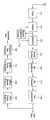
도 3은 이를 위한 본 발명에 따른 디지털 송신 시스템의 전체 구성 블록도이다. 도 3은 EVSB 전처리부(301), EVSB 패킷 포맷터(302), 패킷 다중화기(303), 데이터 랜더마이저(304), EVSB 후처리부(310), RS 엔코더(321), 데이터 인터리버(322), 트렐리스 부호화부(323), 호환성 처리부(324), 프레임 다중화기(325), 및 송신부(330)로 구성된다.3 is a block diagram showing the overall configuration of a digital transmission system according to the present invention. 3 shows an
이와 같이 구성된 본 발명에서 메인 데이터는 트랜스 포트 패킷 단위로 패킷 다중화기(303)로 출력되고, 인핸스드 데이터는 EVSB 전처리부(301)로 출력된다. 상기 EVSB 전처리부(301)는 인핸스드 데이터에 대해 추가의 에러 정정 부호화, 널 데이터 삽입 등과 같은 전처리를 수행한 후 EVSB 패킷 포맷터(302)로 출력한다.In the present invention configured as described above, the main data is output to the
상기 EVSB 패킷 포맷터(302)는 상기 전처리된 데이터와 기정의된 기지 데이터를 패킷의 특정위치에 일정한 규칙에 의해 정렬되도록 하고 일정한 단위의 패킷으로 패킷 다중화기(303)로 출력한다. 상기 EVSB 패킷 포맷터(302)의 상세 동작은 뒤에서 상세히 설명한다.The EVSB
상기 패킷 다중화기(303)는 상기 EVSB 패킷 포맷터(302)에서 기지 데이터가 삽입되어 출력되는 인핸스드 데이터 패킷과 메인 데이터 패킷을 기 정의된 다중화 규칙에 따라 다중화하여 데이터 랜더마이저(304)를 통해 EVSB 후처리부(310)로 출력한다.The
상기 EVSB 후처리부(310)는 RS 엔코더(311), 데이터 인터리버(312), 길쌈 부호화기(313), 데이터 디인터리버(314), RS 바이트 제거기(315)를 포함하여 구성된다.The EVSB
상기 RS 엔코더(311)는 데이터 랜더마이저(304)의 출력에 대해 RS 엔코딩을 수행하여 20바이트의 패리티 데이터를 부가한 후 데이터 인터리버(312)로 출력한다.The
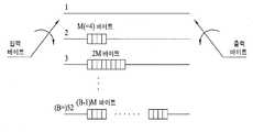
도 4는 상기 데이터 인터리버(312)의 일 실시예를 보인 도면으로서, 브랜치 갯수가 52이고, 단위 메모리 바이트 수 M=4인 길쌈 인터리버의 예를 보이고 있다.FIG. 4 is a diagram illustrating an embodiment of the
상기 데이터 인터리버(312)는 일 예로 먼저, 첫번째 바이트가 입력되면 제1 브랜치를 통하여 바로 출력이 되고, 두번째 바이트는 제2 브랜치를 통하여 입력되고, 이것에 의해 52*4 바이트 이전의 값이 출력된다.For example, the
도 5는 도 3의 데이터 인터리버의 입력과 출력 순서의 예를 프레임 상에서 보인 것이다. 데이터 입력은 세그먼트 단위로 위에서 아래로 입력되며, 세그먼트 내의 바이트는 왼쪽에서 오른쪽으로 시간적으로 먼저 입력된다. 도면 위의 숫자는 인터리버의 출력 순서를 나타낸 것이다. 상기 데이터 인터리버(312)는 52 세그먼트 단위로 동작하고 있다.FIG. 5 shows an example of an input and output order of the data interleaver of FIG. 3 on a frame. Data input is entered from top to bottom in segment units, and bytes within the segment are entered first temporally from left to right. The numbers on the figure show the output order of the interleaver. The data interleaver 312 operates in units of 52 segments.
상기 데이터 인터리버(312)의 출력은 길쌈 부호화기(313)에서 길쌈 부호화되 고, 데이터 디인터리버(314)에서 디인터리빙된 후, RS 바이트 제거기(315)로 입력되어 20바이트의 패리티가 제거된다. 이는 길쌈 부호화기(313)에 의해 원래의 데이터가 변경되었으므로 다시 패리티를 계산하기 위해서이다.The output of the data interleaver 312 is convolutionally coded by the
즉, 상기 RS 바이트 제거기(315)의 출력은 RS 엔코더(321)로 입력되어 RS 엔코딩되고, 20바이트의 패리티가 다시 부가된 후 데이터 인터리버(322)로 출력된다.That is, the output of the
상기 데이터 인터리버(322)의 동작은 도 3, 도 4를 참조하면 되므로 상세 설명을 생략한다.The operation of the data interleaver 322 may be omitted by referring to FIGS. 3 and 4.
상기 데이터 인터리버(322)의 출력은 트렐리스 부호화부(323)로 입력되고, 상기 트렐리스 부호화부(323)는 입력 2비트를 3비트로 코딩하여 출력한 후 프레임 다중화기(325)로 출력한다.The output of the data interleaver 322 is input to the
상기 트렐리스 부호화부(323)의 출력 데이터를 송/수신측에서 정의한 기지 데이터로 하기 위해 인핸스드 패킷에 삽입된 기지 데이터에 대해서 트렐리스 부호화부(323) 내의 메모리의 초기화가 필요하다.In order to use the output data of the
이때 상기 초기화가 입력 데이터가 아닌 새로운 데이터에 의해 이루어지므로, RS 패리티를 다시 생성하여 원래의 패리티 데이터와 치환하여야 한다. 이를 호환성 처리부(324)에서 수행한다. 상기 트렐리스 부호화부(323)의 초기화 과정과 호환성 처리부(324)의 상세 동작도 후술한다.In this case, since the initialization is performed by new data rather than input data, RS parity must be regenerated and replaced with original parity data. The
상기 트렐리스 부호화부(325)의 출력은 프레임 다중화기(325)로 입력되고, 상기 프레임 다중화기(325)는 트렐리스 부호화부(325)의 출력에 필드 동기와 세그먼트 동기를 삽입하여 송신부(330)로 출력한다. 상기 송신부(330)는 파일롯 삽입 부(331), VSB 변조기(333), RF 컨버터(334)로 구성되며, 도1을 참조하여 상세 설명을 생략한다.The output of the
다음은 상기 패킷 포맷터(302)의 상세 동작을 설명한다.Next, detailed operations of the
도 6은 도3의 패킷 포맷터의 내부구성도로서, 기지 데이터를 생성하는 기지데이터 발생부(511)와, 상기 EVSB 전처리부(301)에서 전처리 과정을 거친 데이터와 MPEG 헤더 바이트를 다중화하여 출력하는 다중화기(513)로 구성된다.FIG. 6 is an internal configuration diagram of the packet formatter of FIG. 3. The known
좀 더 상세히 설명하자면, 상기 다중화되어 출력되는 기지데이터는 인터리빙과정 및 트렐리스 부호화 과정을 거친 후 최종 전송전의 VSB 전송 프레임의 구조상에서 종래 기준 데이터로 사용되었던 동기 데이터 외의 별도의 기준 데이터로서 수신기에서 채널 등화 및 복조기에 사용된다. 이렇게 함으로서 수신 성능을 향상시킬 수 있다. 또한 패킷 포맷터의 출력은 188Byte단위로 출력된다. 처음 4바이트는 MPEG 헤더 바이트이고, 나머지 184 바이트는 기지 데이터와 EVSB 전처리부(301)의 출력 데이터가 다중화되어 있다.In more detail, the multiplexed and known data output from the receiver as separate reference data other than the synchronous data used as conventional reference data in the structure of the VSB transmission frame before the final transmission after the interleaving process and the trellis encoding process Used for channel equalization and demodulation. In this way, the reception performance can be improved. In addition, the output of the packet formatter is output in units of 188 bytes. The first 4 bytes are MPEG header bytes, and the remaining 184 bytes are multiplexed from the known data and the output data of the
도 7은 상기 EVSB 후처리부(310)의 RS 엔코더(321)에서 출력되는 데이터를 프레임 구조로 보인 것으로서, 최종 전송되는 프레임은 아니다. 즉 프레임 내 데이터 세그먼트들의 일부를 보인 것으로서, 패킷 포맷터(302)에서 기지 데이터를 삽입하는 예를 보인 것이다. 도 7은 편의상 이해를 돕기 위해 인터리빙 깊이인 52 세그먼트의 구성을 보인 것이다.FIG. 7 shows the data output from the
도 7을 보면, 크게 4개의 데이터 영역으로 이루어진다. 즉, 헤더 영역(701), 인핸스드 데이터만 올 수 있는 페이로드 영역(702), 패리티 영역(703), 및 기지 데 이터가 올 수 있는 기지 데이터 영역(704)으로 구성된다.Referring to FIG. 7, there are largely four data areas. That is, the
상기 기지 데이터 영역(704)은 다시 크게 트렐리스 부호화부(323)의 초기화가 가능한 영역(705), 트렐리스 부호화부의 초기화가 가능하지 영역(706)으로 구분된다.The known
상기 트렐리스 부호화부의 초기화가 가능한 영역(705)은 해당 세그먼트의 패리티 바이트보다 시간적으로 먼저 인터리버에서 출력되는 바이트들의 위치이다. 이때 트렐리스 부호화부(323)로 입력되는 데이터가 인핸스드 데이터 또는 메인 데이터에서 기지 데이터로 바뀔 때 트렐리스 부호화부의 초기화가 가능한 영역(705)의 일부 또는 모든 데이터가 초기화 데이터로 치환되어 트렐리스 부호화부(323)의 메모리로 입력된다. 상기 트렐리스 부호화부의 초기화가 가능한 영역(705)에도 일부 또는 모두 기지 데이터가 올 수도 있고, 인핸스드 데이터가 올 수도 있다.The
상기 트렐리스 부호화부의 초기화가 가능하지 않은 영역(706)에는 기지 데이터가 올 수도 있고, 일반 인핸스드 데이터가 올 수도 있으며, 두 데이터의 영역 크기는 설계자에 의해 적절하게 변형 가능하다. 즉, 기지 데이터와 인핸스드 데이터 량은 상호 상대적이다.In the
그리고 상기 트렐리스 부호화부의 초기화가 가능한 영역(705)과 가능하지 않은 영역(706)의 크기는 각 세그먼트마다 달라진다.In addition, the sizes of the
본 발명에서는 인터리빙 단위로 정해지는 세그먼트 순서에 따라 달라지는 것을 일 실시예로 설명한다.According to an embodiment of the present invention, the embodiment of the present invention will vary according to the segment order determined by the interleaving unit.
도 8은 전송 프레임 구조에서 각 세그먼트 순서와 각 세그먼트 내의 데이터 의 구성의 일부를 보인 것이다. 이렇게 하는 것은 데이터 인터리빙 후에 가능한 각 세그먼트의 기지 데이터들을 특정 영역에 모일 수 있도록 하기 위한 것이다.8 shows a part of each segment order and a structure of data in each segment in the transport frame structure. This is done so that known data of each segment possible after data interleaving can be collected in a specific area.
일 예로, 인터리빙 깊이가 52이고, 그 순서(e)가 13과 같거나 크고, 30보다 같거나 작은 세그먼트에서는 헤더 영역 다음에 트렐리스 부호화부의 초기화가 가능하지 않은 영역, 초기화가 가능한 영역, 페이로드 영역이 순차적으로 존재하며, 상기 영역들이 4번 반복되고 나서 패리티 영역이 존재한다.For example, in a segment having an interleaving depth of 52 and a sequence (e) equal to or greater than 13 and less than or equal to 30, an area in which the trellis encoder cannot be initialized after the header area, an area that can be initialized, and a pay The load regions exist sequentially, and the parity region exists after the regions are repeated four times.
이와 같은 구조로 데이터 인터리버(322)에서 데이터가 인터리빙되면 도 9와 같은 프레임 구조를 갖는다.When data is interleaved in the data interleaver 322 with the above structure, it has a frame structure as shown in FIG.
도 9를 보면, 먼저 헤더 영역들의 데이터가 있고, 이어 기지 데이터 영역들의 데이터가 있다. 즉, 데이터 인터리빙 전 각 세그먼트 내에 흩어져 있던 기지 데이터들이 데이터 인터리빙 후 다수개의 세그먼트에 모여진 것을 볼 수 있다. 상기 기지 데이터 영역들 다음에는 패리티 영역들의 데이터와 페이로드 영역들의 데이터가 있다.9, there is data of header areas first, followed by data of known data areas. That is, it can be seen that known data scattered in each segment before data interleaving are collected in a plurality of segments after data interleaving. Following the known data areas are data of parity areas and data of payload areas.
도 10은 상기 데이터 인터리버(322)에서 도 9와 같이 인터리빙된 데이터를 이용하여 트렐리스 부호화하는 초기화 가능한 트렐리스 부호화부(323)의 상세 블록도의 일 실시예를 보이고 있다.FIG. 10 illustrates an example of a detailed block diagram of an
도 10을 보면, 인터리빙된 데이터, 호환성 처리부(324)에서 출력되는 패리티 바이트, 초기화 데이터를 기 정해진 규칙에 따라 다중화하여 출력하는 다중화기(611), 상기 다중화기(611)의 출력 데이터를 트렐리스 부호화하여 출력하는 트렐리스 부호기(612), 및 상기 트렐리스 부호기(612)의 메모리를 초기화하기 위한 초 기화 데이터를 생성하여 상기 다중화기(611)와 호환성 처리부(324)로 출력하는 초기화 제어부(613)로 구성된다.Referring to FIG. 10, a
즉, 인터리빙된 데이터가 기지 데이터이고, 상기 기지 데이터가 연속적으로 입력되는 기지 데이터열의 처음이면 트렐리스 부호기(612)의 초기화가 필요하다. 상기 기지 데이터 열이 시작될 때 트렐리스 부호기(612)를 초기화하는 이유는 트렐리스 부호기(612) 입력으로 기지 데이터의 열이 입력되더라도 트렐리스 부호기(612)의 메모리 상태에 따라서 여러 가지 출력 열이 가능하기 때문이다. 따라서 트렐리스 부호기(612)의 메모리 상태를 정해진 값으로 초기화한 후에 기지 데이터를 입력하면 트렐리스 부호기 출력에서도 기지 데이터 출력 열을 얻을 수 있다.In other words, if the interleaved data is known data and the beginning of the known data string to which the known data is continuously input, the
그러므로, 상기 트렐리스 부호기(612)의 메모리 초기화가 필요한 경우 상기 기지 데이터의 일부가 초기화 데이터로 치환되어 상기 트렐리스 부호기(612)로 출력되어야 한다. 그러면 상기 트렐리스 부호기(612) 내 메모리는 상기 초기화 데이터에 의해 초기화되고, 상기 트렐리스 부호기(612)의 출력은 송/수신측에서 원하는 형태의 부호화된 기지 데이터를 출력하게 된다.Therefore, when memory initialization of the
이를 위해 인터리빙되어 출력되는 데이터가 기지 데이터이고, 초기화가 필요하다고 하면 상기 다중화기(611)는 인터리빙된 데이터의 일부를 초기화 제어부(613)에서 출력되는 초기화 데이터로 치환하여 트렐리스 부호기(612)로 출력하고, 각 인핸스드 데이터 세그먼트 내 패리티 위치에서는 상기 호환성 처리부(324)에서 출력되는 패리티 데이터를 상기 트렐리스 부호기(612)로 출력하며, 그 이외의 경우에는 인터리빙된 데이터를 상기 트렐리스 부호기(612)로 출력한다.For this purpose, if the data interleaved and output are known data, and initialization is required, the
상기 트렐리스 부호기(612)는 상기 다중화기(611)에서 출력되는 데이터에 대해 심볼 단위로 트렐리스 부호화한다. 상기 심볼은 2비트로 구성된다. 설명의 편의를 위해 상기 심볼을 구성하는 2비트 중 상위 비트를 d1이라 하고, 하위 비트를 d0라 한다.The
도 11은 상기 트렐리스 부호기(612)의 일 실시예를 보인 상세 블록도로서, 두 개의 비트(d1,d0)를 입력으로 받아서 세 개의 비트(c2,c1,c0)를 출력한다.FIG. 11 is a detailed block diagram showing an embodiment of the
이를 위해 트렐리스 부호기(612)는 TCM(Trellis Coded Modulation) 부호기(621)와 프리코더(622)로 구성된다. 그리고 입력 심볼 중 하위 비트(d0)는 TCM 부호기(621)로 입력되고, 상위 비트(d1)는 프리 코더(622)로 입력된다.To this end, the
상기 TCM 부호기(621)는 입력 비트(d0)를 그대로 제2 출력비트(c1)로 바이패스하는 라인, 피드백되는 제1 출력비트(c0)를 일시 저장한 후 출력하는 메모리(m1), 상기 입력 비트(d0)와 메모리(m1)의 출력을 더하여 출력하는 가산기, 및 상기 가산기의 출력을 일시 저장한 후 제1 출력비트(c0)로 출력함과 동시에 메모리(m1)로 피드백하는 메모리(m0)로 구성된다.The
상기 프리코더(621)는 입력 비트(d1)와 피드백되는 신호를 더하여 제3 출력비트(c2)로 출력하는 가산기, 및 상기 가산기에서 출력되는 제3 출력비트(c2)를 일시 저장한 후 상기 가산기로 피드백하는 메모리(m2)로 구성된다.The
이때 상기 각 메모리(m0~m2)는 동일한 클럭을 제공받고, 입력 클럭에 동기되어 동작하는 것을 일 실시예로 한다.At this time, each of the memories m0 to m2 is provided with the same clock and operates in synchronization with the input clock.
이와 같이 구성된 도 11에서, 하위비트(d0)는 그대로 제2 출력비트(c1)로 출 력됨과 동시에 TCM 부호기(621)의 2개의 메모리(m0,m1)와 가산기에 의해 트렐리스 부호화되어 제1 출력비트(c0)로 출력된다.In FIG. 11 configured as described above, the lower bit d0 is output as it is to the second output bit c1 and trellis coded by two memories m0 and m1 and an adder of the
그리고 상위 비트(d1)는 프리코더(622)의 가산기와 메모리(m2)에 의해 프리코딩되어 제3 출력비트(c2)로 출력된다.The upper bit d1 is precoded by the adder of the
따라서, 상기 트렐리스 부호기(612)의 메모리(m2)는 상위 비트(d1)에 의해서만 결정이 되고, 메모리(m1, m0)는 하위 비트(d0)에 의해서만 결정됨을 알 수 있다.Accordingly, it can be seen that the memory m2 of the
그리고 도면을 보면 알 수 있듯이 상기 트렐리스 부호기(612)의 메모리(m2) 를 어떤 정해진 값으로 초기화하기 위해서는 한 개의 d1 비트를 사용하면 가능하고, 메모리(m1, m0)를 어떤 정해진 값으로 초기화하기 위해서는 두 개의 d0 비트가 필요하다. 따라서 트렐리스 부호기(612)의 메모리 m2, m1, m0를 초기화하기 위해서는 적어도 2개의 입력 심볼이 필요함을 알 수 있다.As can be seen from the figure, in order to initialize the memory m2 of the
하기 표 1은 임의의 m2m1m0의 상태에서 이를 000 상태로 초기화하기 위해 필요한 두 심볼의 입력을 설명하고 있다.Table 1 below describes the input of two symbols needed to initialize it to the 000 state in any m2m1m0 state.
예를 들어, m2m1m0 = 111인 상태에서 이것을 000으로 초기화하기 위해서는 d1d0 입력 심볼이 연속적으로 01, 11로 입력되거나 또는 11, 01로 입력되어야 한다.For example, when m2m1m0 = 111, in order to initialize this to 000, the d1d0 input symbol must be continuously inputted as 01, 11 or 11, 01.
이를 위해 상기 초기화 제어부(613)는 트렐리스 부호기의 메모리(m2m1m0) 상태 값을 입력받고, 상기 표 1를 참조하여 초기화에 필요한 입력 심볼열을 생성한 후 다중화기(611)로 출력한다. 즉, 상기 초기화 제어부(613)는 메모리 초기화가 필요한 경우 메모리(m2m1m0)의 상태와 표 1을 참조하여 초기화 데이터를 생성한 후 상기 다중화기(611)로 출력한다.To this end, the
이때 상기 VSB 송신 시스템 내 트렐리스 부호기는 12개로 구성되고, 각 트렐리스 부호기의 메모리를 초기화하기 위해서는 2개의 심볼이 필요하므로, 기지 데이터열이 시작될 때 처음 24개의 입력 심볼이 초기화에 사용된다.In this case, since 12 trellis encoders in the VSB transmission system are configured and two symbols are required to initialize the memory of each trellis encoder, the first 24 input symbols are used for initialization when a known data sequence starts. .
상기 트렐리스 부호기(612)의 메모리를 초기화하려는 상태가 000이 아닐 경우에는 표 1에서와는 다른 두 개의 심볼열이 필요하나 이것은 쉽게 추론할 수 있으므로 본 발명에서는 생략하겠다.When the state of the memory of the
또한 상기 초기화 제어부(613)는 초기화 데이터를 호환성 처리부(324)로 출력한다.In addition, the
즉 상기 인터리빙된 데이터가 아닌 새로운 데이터에 의해 상기 메모리의 초기화가 이루어지므로, RS 패리티를 다시 생성하여 원래의 패리티 데이터와 치환하여야 한다.That is, since the memory is initialized by new data instead of the interleaved data, RS parity must be regenerated and replaced with original parity data.
이를 호환성 처리부(324)에서 수행한다.The
상기 호환성 처리부(324)는 RS 엔코더(321)의 출력과 트렐리스 부호화부(323)의 초기화 제어부(613)의 출력을 입력받아 20바이트의 패리티를 생성한 후 다중화기(611)로 출력한다.The
상기 트렐리스 부호화부(323)의 출력은 프레임 다중화기(325)로 출력된다.The output of the
상기 프레임 다중화기(325)는 상기 트렐리스 부호화부(323)의 출력에 필드 동기와 세그먼트 동기를 삽입한 후 송신부(330)를 통해 전송한다.The
도 12는 도 3과 같은 VSB 송신 시스템에서 전송되는 데이터를 수신하여 복조 및 등화하여 원래 데이터로 복원하는 VSB 수신 시스템의 일 실시예를 보인 구성 블록도이다.FIG. 12 is a block diagram illustrating an embodiment of a VSB receiving system for receiving, demodulating, and equalizing data transmitted from a VSB transmitting system as shown in FIG. 3 to restore original data.
도 12는 튜너(711), 복조부(712), 등화기(713), 기지 데이터 검출부(714), 비터비 디코더(715), 디인터리버(716), RS 디코더(717), 디랜더마이저(718)를 포함하여 구성된다.12 shows a
또한 상기 VSB 수신 시스템은 메인 패킷 제거부(719), MPEG 헤더 제거부(720), 패킷 디포맷터(721), 인핸스드 데이터 처리부(722)를 포함하여 구성된다.In addition, the VSB receiving system includes a
즉, 상기 튜너(711)는 특정 채널의 주파수를 튜닝하여 다운 컨버팅한 후 복조부(712)로 출력한다.That is, the
상기 복조부(712)는 튜닝된 채널 주파수에 대해 반송파 복구, 타이밍 복구 등을 수행하여 등화기(713)로 출력한다.The
상기 등화기(712)는 상기 복조된 신호에 포함된 채널 상의 왜곡을 보상한 후 비터비 디코더(715)로 출력한다.The
이때 상기 기지 데이터 검출부(714)는 상기 복조부(712)의 출력 데이터로부터 송신측에서 삽입한 기지 데이터를 검출한 후 복조부(712)와 등화기(713)로 출력한다.At this time, the known
상기 복조부(712)는 타이밍 복원이나 반송파 복구시에 상기 기지 데이터를 이용함으로써, 복조 성능을 향상시킬 수 있고, 등화기(713)는 채널 등화에 상기 기지 데이터를 이용함으로써, 등화 성능을 향상시킬 수 있다.The
상기 등화기(713)의 출력이 비터비 디코더(715), 디인터리버(716), RS 디코더(717), 및 디랜더마이저(718)를 거친 후 메인 MPEG 디코더(도시되지 않음)로 출력됨과 동시에 메인 패킷 제거부(719)로 출력된다.The output of the
상기 비터비 디코더(715)는 상기 등화기(713)에서 출력되는 데이터에 대하여 비터비 복호를 수행하여 바이트로 변환한 후 이를 디인터리버(716)로 출력한다. 상기 디인터리버(716)는 송신측의 데이터 인터리버의 역과정을 수행하여 RS 디코더(717)로 출력한다. 상기 RS 디코더(717)는 입력 데이터 패킷으로부터 패리티 데이터를 제거하여 디랜더마이져(718)로 출력한다.The
상기 디랜더마이져(718)는 RS 디코더(717)의 출력에 대하여 랜더마이져의 역과정을 수행하고 MPEG 동기 바이트를 매 패킷의 앞에 삽입하여 188 바이트 패킷 단위로 출력한다.The
상기 디랜더마이져(718)의 출력은 메인 MPEG 디코더(도시되지 않음)로 출력됨과 동시에 메인 데이터 패킷 제거부(719)로 출력된다. 상기 메인 MPEG 디코더는 메인 MPEG에 해당하는 패킷에 대해서만 디코딩을 수행한다. 만일 패킷 ID가 널 패킷 PID 혹은 기존 ATSC 시스템에서 그 사용인 reserved 된 PID(즉, 인핸스드 데이터 패킷)이면 디코딩을 하지 않는다.The output of the
한편 상기 메인 데이터 패킷 제거부(719)는 디랜더마이져(718)의 출력으로부터 메인 데이터 패킷을 제거하여 MPEG 헤더 제거부(720)로 출력한다. 상기 MPEG 헤더 제거부(720)는 메인 패킷 제거부(719)에서 출력되는 신호로부터 MPEG 헤더를 제거한 후 패킷 디포맷터(721)로 출력한다. 상기 패킷 디포맷터(721)는 입력되는 신호에 포함된 기지 데이터를 제거한 후 인핸스드 데이터 처리부(722)로 출력한다. 상기 인핸스드 데이터 처리부(722)는 상기 패킷 디포맷터(721)의 출력에 대해 송신측의 EVSB 전처리부의 역과정을 수행하여 최종으로 인핸스드 데이터를 출력한다.The main
이상 설명한 내용과 같이 당업자라면 본 발명의 기술 사상을 이탈하지 아니하는 범위에서 다양한 변경 및 수정이 가능함을 알 수 있을 것이다. 따라서, 본 발명의 기술적 범위는 실시예에 기재된 내용으로 한정되는 것이 아니라 특허 청구의 범위에 의하여 정해져야 한다.As described above, those skilled in the art will appreciate that various changes and modifications can be made without departing from the spirit of the present invention. Therefore, the technical scope of the present invention should not be limited to the contents described in the embodiments, but should be defined by the claims.
도1은 일반적인 디지털 방송 송신 시스템의 구성 블록도1 is a block diagram of a general digital broadcast transmission system
도 2는 일반적인 VSB 전송 프레임의 구조를 보인 도면2 is a view showing the structure of a typical VSB transmission frame
도 3은 본 발명에 따른 디지털 방송 송신 시스템의 구성 블록도3 is a block diagram of a digital broadcast transmission system according to the present invention.
도 4는 도 3의 데이터 인터리버의 일 실시예를 보인 구성 블록도4 is a block diagram illustrating an embodiment of the data interleaver of FIG. 3.
도 5는 도 3의 데이터 인터리버의 동작 예를 프레임 상에서 보인 도면5 is a diagram illustrating an example of an operation of the data interleaver of FIG. 3 on a frame;
도 6은 도 3의 패킷 포맷터의 일 실시예를 보인 상세 블록도FIG. 6 is a detailed block diagram illustrating an embodiment of the packet formatter of FIG. 3. FIG.
도 7은 본 발명에 따른 인터리빙 전의 기지 데이터의 삽입 예를 프레임 구조로 보인 도면7 illustrates a frame structure showing an example of inserting known data before interleaving according to the present invention.
도 8은 도 7의 기지 데이터의 삽입 예를 각 세그먼트별로 구분하여 보인 도면FIG. 8 is a diagram illustrating an example of inserting known data of FIG. 7 by segment. FIG.
도 9는 본 발명에 따른 인터리빙 후의 기지 데이터의 삽입 예를 프레임 구조로 보인 도면9 is a view showing a frame structure of an example of insertion of known data after interleaving according to the present invention;
도 10은 본 발명의 일 실시예에 따른 트렐리스 부호화부의 상세 블록도10 is a detailed block diagram of a trellis encoder according to an embodiment of the present invention.
도 11은 도 10의 트렐리스 부호기의 일 실시예를 보인 상세 블록도11 is a detailed block diagram illustrating an embodiment of the trellis encoder of FIG. 10.
도 12는 본 발명에 따른 디지털 방송 수신 시스템의 일 실시예를 보인 전체 구성 블록도12 is a block diagram showing the overall configuration of an embodiment of a digital broadcast receiving system according to the present invention.
도면의 주요 부분에 대한 부호의 설명Explanation of symbols for the main parts of the drawings
301 : EVSB 전처리부302 : EVSB 패킷 포맷터301: EVSB preprocessor 302: EVSB packet formatter
303 : 패킷 다중화기304 : 데이터 랜덤마이저303: packet multiplexer 304: data randomizer
310 : EVSB 후처리부311 : RS 엔코더310: EVSB post-processing unit 311: RS encoder
312 : 데이터 인터리버313 : 길쌈 부호화기312 data interleaver 313 convolutional encoder
314 : 데이터 디인터리버315 : RS 바이트 제거기314: Data Deinterleaver 315: RS Byte Eliminator
321 : RS 엔코더322 : 데이터 인터리버321 RS encoder 322 data interleaver
323 : 트렐리스 부호화부324 : 호환성 처리부323
325 : 프레임 다중화기330 : 송신부325: frame multiplexer 330: transmitter
Claims (6)
Translated fromKoreanPriority Applications (1)
| Application Number | Priority Date | Filing Date | Title |
|---|---|---|---|
| KR1020090003835AKR100904445B1 (en) | 2009-01-16 | 2009-01-16 | Broadcast transmitter / receiver and broadcast signal processing method |
Applications Claiming Priority (1)
| Application Number | Priority Date | Filing Date | Title |
|---|---|---|---|
| KR1020090003835AKR100904445B1 (en) | 2009-01-16 | 2009-01-16 | Broadcast transmitter / receiver and broadcast signal processing method |
Related Parent Applications (1)
| Application Number | Title | Priority Date | Filing Date |
|---|---|---|---|
| KR1020050094074ADivisionKR101147760B1 (en) | 2005-10-06 | 2005-10-06 | Transmitting/ receiving system and method of digital broadcasting, and data structure |
Publications (2)
| Publication Number | Publication Date |
|---|---|
| KR20090014235A KR20090014235A (en) | 2009-02-06 |
| KR100904445B1true KR100904445B1 (en) | 2009-06-26 |
Family
ID=40684295
Family Applications (1)
| Application Number | Title | Priority Date | Filing Date |
|---|---|---|---|
| KR1020090003835AExpired - Fee RelatedKR100904445B1 (en) | 2009-01-16 | 2009-01-16 | Broadcast transmitter / receiver and broadcast signal processing method |
Country Status (1)
| Country | Link |
|---|---|
| KR (1) | KR100904445B1 (en) |
Citations (2)
| Publication number | Priority date | Publication date | Assignee | Title |
|---|---|---|---|---|
| KR20030026236A (en)* | 2001-09-24 | 2003-03-31 | 코닌클리케 필립스 일렉트로닉스 엔.브이. | An improved digital transmission system for an enhanced ATSC 8-VSB system |
| US6760077B2 (en) | 2001-01-19 | 2004-07-06 | Lg Electronics, Inc. | VSB reception system with enhanced signal detection for processing supplemental data |
- 2009
- 2009-01-16KRKR1020090003835Apatent/KR100904445B1/ennot_activeExpired - Fee Related
Patent Citations (2)
| Publication number | Priority date | Publication date | Assignee | Title |
|---|---|---|---|---|
| US6760077B2 (en) | 2001-01-19 | 2004-07-06 | Lg Electronics, Inc. | VSB reception system with enhanced signal detection for processing supplemental data |
| KR20030026236A (en)* | 2001-09-24 | 2003-03-31 | 코닌클리케 필립스 일렉트로닉스 엔.브이. | An improved digital transmission system for an enhanced ATSC 8-VSB system |
Non-Patent Citations (1)
| Title |
|---|
| A/53D ATSC Standard: Digital Television Standard (A/53), Revision D, Including Amendment No. 1 , 27 July 2005 |
Also Published As
| Publication number | Publication date |
|---|---|
| KR20090014235A (en) | 2009-02-06 |
Similar Documents
| Publication | Publication Date | Title |
|---|---|---|
| KR101191181B1 (en) | Transmitting/receiving system of digital broadcasting and data structure | |
| KR101147760B1 (en) | Transmitting/ receiving system and method of digital broadcasting, and data structure | |
| KR101208504B1 (en) | Digital broadcasting system and processing method | |
| KR101191182B1 (en) | Digital broadcasting system and processing method | |
| CA2625160C (en) | Digital broadcasting system and method | |
| US7783960B2 (en) | DTV transmitter and method of coding main and enhanced data in DTV transmitter | |
| KR101147759B1 (en) | Transmitting/receiving system of digital broadcasting | |
| CA2565863C (en) | Digital broadcasting transmission/reception devices capable of improving a receiving performance and signal processing method thereof | |
| KR101208509B1 (en) | Digital broadcasting system and processing method | |
| KR20060063867A (en) | Broadcast Systems and Methods of Processing Data in Broadcast Systems | |
| KR100904445B1 (en) | Broadcast transmitter / receiver and broadcast signal processing method | |
| KR100908065B1 (en) | Broadcast transmitter / receiver and broadcast signal processing method | |
| KR100949973B1 (en) | Broadcast transmitter / receiver and broadcast signal processing method | |
| KR100925448B1 (en) | Broadcast transmitter / receiver and broadcast signal processing method |
Legal Events
| Date | Code | Title | Description |
|---|---|---|---|
| A107 | Divisional application of patent | ||
| PA0107 | Divisional application | St.27 status event code:A-0-1-A10-A16-div-PA0107 St.27 status event code:A-0-1-A10-A18-div-PA0107 | |
| A201 | Request for examination | ||
| A302 | Request for accelerated examination | ||
| PA0201 | Request for examination | St.27 status event code:A-1-2-D10-D11-exm-PA0201 | |
| PA0302 | Request for accelerated examination | St.27 status event code:A-1-2-D10-D16-exm-PA0302 St.27 status event code:A-1-2-D10-D17-exm-PA0302 | |
| PG1501 | Laying open of application | St.27 status event code:A-1-1-Q10-Q12-nap-PG1501 | |
| R18-X000 | Changes to party contact information recorded | St.27 status event code:A-3-3-R10-R18-oth-X000 | |
| E701 | Decision to grant or registration of patent right | ||
| PE0701 | Decision of registration | St.27 status event code:A-1-2-D10-D22-exm-PE0701 | |
| GRNT | Written decision to grant | ||
| PR0701 | Registration of establishment | St.27 status event code:A-2-4-F10-F11-exm-PR0701 | |
| PR1002 | Payment of registration fee | Fee payment year number:1 St.27 status event code:A-2-2-U10-U11-oth-PR1002 | |
| PG1601 | Publication of registration | St.27 status event code:A-4-4-Q10-Q13-nap-PG1601 | |
| R18-X000 | Changes to party contact information recorded | St.27 status event code:A-5-5-R10-R18-oth-X000 | |
| PR1001 | Payment of annual fee | Fee payment year number:4 St.27 status event code:A-4-4-U10-U11-oth-PR1001 | |
| FPAY | Annual fee payment | Payment date:20130514 Year of fee payment:5 | |
| PR1001 | Payment of annual fee | Fee payment year number:5 St.27 status event code:A-4-4-U10-U11-oth-PR1001 | |
| FPAY | Annual fee payment | Payment date:20140523 Year of fee payment:6 | |
| PR1001 | Payment of annual fee | Fee payment year number:6 St.27 status event code:A-4-4-U10-U11-oth-PR1001 | |
| FPAY | Annual fee payment | Payment date:20150522 Year of fee payment:7 | |
| PN2301 | Change of applicant | St.27 status event code:A-5-5-R10-R11-asn-PN2301 St.27 status event code:A-5-5-R10-R13-asn-PN2301 | |
| PR1001 | Payment of annual fee | Fee payment year number:7 St.27 status event code:A-4-4-U10-U11-oth-PR1001 | |
| FPAY | Annual fee payment | Payment date:20160524 Year of fee payment:8 | |
| PR1001 | Payment of annual fee | Fee payment year number:8 St.27 status event code:A-4-4-U10-U11-oth-PR1001 | |
| FPAY | Annual fee payment | Payment date:20170512 Year of fee payment:9 | |
| PR1001 | Payment of annual fee | Fee payment year number:9 St.27 status event code:A-4-4-U10-U11-oth-PR1001 | |
| P22-X000 | Classification modified | St.27 status event code:A-4-4-P10-P22-nap-X000 | |
| FPAY | Annual fee payment | Payment date:20180514 Year of fee payment:10 | |
| PR1001 | Payment of annual fee | Fee payment year number:10 St.27 status event code:A-4-4-U10-U11-oth-PR1001 | |
| FPAY | Annual fee payment | Payment date:20190514 Year of fee payment:11 | |
| PR1001 | Payment of annual fee | Fee payment year number:11 St.27 status event code:A-4-4-U10-U11-oth-PR1001 | |
| PR1001 | Payment of annual fee | Fee payment year number:12 St.27 status event code:A-4-4-U10-U11-oth-PR1001 | |
| PN2301 | Change of applicant | St.27 status event code:A-5-5-R10-R11-asn-PN2301 St.27 status event code:A-5-5-R10-R13-asn-PN2301 | |
| PR1001 | Payment of annual fee | Fee payment year number:13 St.27 status event code:A-4-4-U10-U11-oth-PR1001 | |
| PR1001 | Payment of annual fee | Fee payment year number:14 St.27 status event code:A-4-4-U10-U11-oth-PR1001 | |
| PC1903 | Unpaid annual fee | Not in force date:20230618 Payment event data comment text:Termination Category : DEFAULT_OF_REGISTRATION_FEE St.27 status event code:A-4-4-U10-U13-oth-PC1903 | |
| PC1903 | Unpaid annual fee | Ip right cessation event data comment text:Termination Category : DEFAULT_OF_REGISTRATION_FEE Not in force date:20230618 St.27 status event code:N-4-6-H10-H13-oth-PC1903 |