KR100904009B1 - Electrostatic coating device - Google Patents
Electrostatic coating deviceDownload PDFInfo
- Publication number
- KR100904009B1 KR100904009B1KR1020077020226AKR20077020226AKR100904009B1KR 100904009 B1KR100904009 B1KR 100904009B1KR 1020077020226 AKR1020077020226 AKR 1020077020226AKR 20077020226 AKR20077020226 AKR 20077020226AKR 100904009 B1KR100904009 B1KR 100904009B1
- Authority
- KR
- South Korea
- Prior art keywords
- housing member
- high voltage
- cover
- paint
- cover member
- Prior art date
- Legal status (The legal status is an assumption and is not a legal conclusion. Google has not performed a legal analysis and makes no representation as to the accuracy of the status listed.)
- Expired - Fee Related
Links
Images


Classifications
- B—PERFORMING OPERATIONS; TRANSPORTING
- B05—SPRAYING OR ATOMISING IN GENERAL; APPLYING FLUENT MATERIALS TO SURFACES, IN GENERAL
- B05B—SPRAYING APPARATUS; ATOMISING APPARATUS; NOZZLES
- B05B5/00—Electrostatic spraying apparatus; Spraying apparatus with means for charging the spray electrically; Apparatus for spraying liquids or other fluent materials by other electric means
- B05B5/025—Discharge apparatus, e.g. electrostatic spray guns
- B05B5/053—Arrangements for supplying power, e.g. charging power
- B05B5/0533—Electrodes specially adapted therefor; Arrangements of electrodes
- B—PERFORMING OPERATIONS; TRANSPORTING
- B05—SPRAYING OR ATOMISING IN GENERAL; APPLYING FLUENT MATERIALS TO SURFACES, IN GENERAL
- B05B—SPRAYING APPARATUS; ATOMISING APPARATUS; NOZZLES
- B05B15/00—Details of spraying plant or spraying apparatus not otherwise provided for; Accessories
- B05B15/50—Arrangements for cleaning; Arrangements for preventing deposits, drying-out or blockage; Arrangements for detecting improper discharge caused by the presence of foreign matter
- B—PERFORMING OPERATIONS; TRANSPORTING
- B05—SPRAYING OR ATOMISING IN GENERAL; APPLYING FLUENT MATERIALS TO SURFACES, IN GENERAL
- B05B—SPRAYING APPARATUS; ATOMISING APPARATUS; NOZZLES
- B05B5/00—Electrostatic spraying apparatus; Spraying apparatus with means for charging the spray electrically; Apparatus for spraying liquids or other fluent materials by other electric means
- B05B5/025—Discharge apparatus, e.g. electrostatic spray guns
- B05B5/04—Discharge apparatus, e.g. electrostatic spray guns characterised by having rotary outlet or deflecting elements, i.e. spraying being also effected by centrifugal forces
- B05B5/0415—Driving means; Parts thereof, e.g. turbine, shaft, bearings
- B—PERFORMING OPERATIONS; TRANSPORTING
- B05—SPRAYING OR ATOMISING IN GENERAL; APPLYING FLUENT MATERIALS TO SURFACES, IN GENERAL
- B05B—SPRAYING APPARATUS; ATOMISING APPARATUS; NOZZLES
- B05B5/00—Electrostatic spraying apparatus; Spraying apparatus with means for charging the spray electrically; Apparatus for spraying liquids or other fluent materials by other electric means
- B05B5/025—Discharge apparatus, e.g. electrostatic spray guns
- B05B5/04—Discharge apparatus, e.g. electrostatic spray guns characterised by having rotary outlet or deflecting elements, i.e. spraying being also effected by centrifugal forces
- B05B5/0426—Means for supplying shaping gas
Landscapes
- Electrostatic Spraying Apparatus (AREA)
Abstract
Translated fromKoreanDescription
Translated fromKorean본 발명은 고전압을 인가한 상태에서 도료를 분무하도록 한 정전 도장 장치에 관한 것이다.The present invention relates to an electrostatic coating apparatus for spraying paint in a state where a high voltage is applied.
일반적으로, 정전 도장 장치로서, 예를 들면 에어 모터와 회전 무화 헤드로 이루어지는 분무기와, 절연 재료로 형성되고 상기 분무기의 에어 모터를 지지하는 하우징 부재와, 상기 하우징 부재의 외표면을 덮고 통형으로 형성된 커버 부재와, 외부 전극을 사용하여 분무기의 회전 무화 헤드로부터 분무된 도료 입자를 마이너스의 고전압에 대전시키는 고전압 발생기를 구비한 것이 알려져 있다(예를 들면, 일본국 특개 2001-113207호 공보 참조).Generally, as an electrostatic coating apparatus, for example, an atomizer comprising an air motor and a rotary atomizing head, a housing member formed of an insulating material and supporting the air motor of the atomizer, and formed in a tubular shape covering the outer surface of the housing member It is known to have a cover member and a high voltage generator for charging paint particles sprayed from the rotating atomizing head of the sprayer to a negative high voltage using an external electrode (see, for example, Japanese Patent Laid-Open No. 2001-113207).
이와 같은 종래 기술에 의한 정전 도장 장치에서는, 마이너스의 고전압이 인가된 외부 전극과 어스 전위로 되는 회전 무화 헤드 사이, 및 외부 전극과 피도장물 사이에는, 각각 전기력선에 의한 정전 경계 지역이 형성된다. 또, 외부 전극의 선단 근방에는 마이너스의 이온화 권역이 형성된다.In such an electrostatic coating apparatus according to the prior art, an electrostatic boundary region by electric force lines is formed between an external electrode to which a negative high voltage is applied, a rotating atomizing head which becomes an earth potential, and an external electrode and a workpiece, respectively. In addition, a negative ionization zone is formed near the tip of the external electrode.
이 상태에서, 고속 회전되는 회전 무화 헤드를 사용하여 도료를 분무하면, 회전 무화 헤드로부터 분무된 도료 입자는, 이온화 권역을 통과함으로써 마이너스의 고전압으로 대전되어, 대전 도료 입자로 된다. 이로써, 대전 도료 입자는, 어 스에 접속된 피도장물를 향해 비행하고, 상기 피도장물의 표면에 도착(塗着)된다.In this state, when spraying paint using a rotating atomizing head rotated at a high speed, the coating particles sprayed from the rotating atomizing head are charged to a negative high voltage by passing through the ionization zone, thereby becoming charged coating particles. As a result, the charged coating particles fly toward the coated object connected to the earth, and reach the surface of the coated object.
그런데, 일본국 특개 2001-113207호 공보에 의한 정전 도장 장치에서는, 커버 부재의 외표면은, 방전되어 있는 마이너스 이온의 마이너스 극성에 대전되어 있다. 그러므로, 서로 마이너스의 동일한 극성인 대전 도료 입자와 커버 부재가 반발하고, 커버 부재의 외표면에 도료 입자가 부착되는 것을 방지하고 있다. 또, 커버 부재 등은, 절연 재료를 사용하여 형성됨으로써, 상기 커버 부재의 외표면에 대전된 고전압의 전하가 어스 전위 측에 누설되는 것을 방지하고 있다.By the way, in the electrostatic coating apparatus of Unexamined-Japanese-Patent No. 2001-113207, the outer surface of a cover member is charged with the negative polarity of the discharged negative ion. Therefore, the charging paint particles and the cover member having negative polarities of each other are repulsed, and the coating particles are prevented from adhering to the outer surface of the cover member. In addition, the cover member or the like is formed using an insulating material, thereby preventing the high voltage electric charge charged on the outer surface of the cover member from leaking to the earth potential side.
그러나, 실제로는, 정전 도장을 계속할수록, 커버 부재의 외표면에는 서서히 도료 입자가 부착되어 부착 도료로 된다. 그러므로, 상기 부착 도료에 의해, 커버 부재의 외표면의 절연도가 저하된다는 문제가 있다. 그리고, 커버 부재의 절연도가 저하되면, 도료의 부착이 급격하게 진행된다. 그러므로, 종래 기술에서는, 부착된 도료를 제거하기 위해, 도장 작업을 자주 중단하지 않을 수 없었다.However, in practice, as the electrostatic coating is continued, the paint particles gradually adhere to the outer surface of the cover member, resulting in an adhered paint. Therefore, there exists a problem that the insulation of the outer surface of a cover member falls by the said adhesion paint. And when the insulation degree of a cover member falls, application of a paint advances rapidly. Therefore, in the prior art, the painting operation was often stopped in order to remove the adhered paint.
또, 일본국 특개 2001-113207호 공보에 의한 정전 도장 장치에서는, 커버 부재의 외표면에 발수성 도료를 도포함으로써, 도료 입자의 부착을 방지하고 있다. 그러나, 상기 도장 장치에서는, 도장 작업의 종료시에 도장 장치의 외표면을 세정함에 따라, 발수성 도료의 막두께가 서서히 얇아지기 때문에, 정기적으로 발수성 도료를 재도포할 필요가 있다. 또, 발수성 도료의 도막의 품질이 안정되지 않기 때문에, 제품 수율이 낮고, 도막 형성 작업 자체 비용도 높아진다는 문제도 있다.Moreover, in the electrostatic coating apparatus of Unexamined-Japanese-Patent No. 2001-113207, application of a water-repellent paint to the outer surface of a cover member prevents adhesion of paint particles. However, in the said coating device, since the outer surface of a coating device wash | cleans the outer surface of a coating device at the end of a painting operation, since the film thickness of a water repellent paint gradually becomes thin, it is necessary to reapply a water repellent paint regularly. Moreover, since the quality of the coating film of a water repellent paint is not stabilized, there also exists a problem that a product yield is low and the cost of coating film formation itself itself becomes high.
본 발명은 전술한 종래 기술의 문제점을 감안하여 이루어진 것으로, 본 발명의 목적은, 커버 부재의 외표면에 고전압을 안정적으로 대전시켜, 도료 입자가 부착되는 것을 방지할 수 있는 정전 도장 장치를 제공하는데 있다.SUMMARY OF THE INVENTION The present invention has been made in view of the above-described problems of the prior art, and an object of the present invention is to provide an electrostatic coating apparatus capable of stably charging a high voltage to an outer surface of a cover member and preventing coating particles from adhering. have.
(1). 전술한 과제를 해결하기 위해, 본 발명은, 공급된 도료를 피도장물에 분무하는 도료 분무 수단과, 절연 재료로 형성되고 상기 도료 분무 수단을 지지하는 하우징 부재와, 절연 재료로 형성되고 상기 하우징 부재의 외표면을 덮고 통형으로 형성된 커버 부재와, 상기 도료 분무 수단으로부터 분무된 도료 입자를 고전압으로 대전시키고 대전 도료 입자를 피도장물에 도착시키는 고전압 인가 수단으로 이루어지는 정전 도장 장치에 있어서, 상기 하우징 부재와 커버 부재 사이에는, 상기 하우징 부재와 커버 부재가 서로 대면하는 부위의 전체면에 걸쳐 공간이 형성되는 것을 특징으로 하고 있다.(One). In order to solve the above-mentioned problems, the present invention provides a paint spraying means for spraying a supplied paint onto a workpiece, a housing member formed of an insulating material and supporting the paint spraying means, and formed of an insulating material and the housing An electrostatic coating apparatus comprising: a cover member covering the outer surface of the member and formed in a tubular shape; and high voltage applying means for charging the paint particles sprayed from the paint spraying means at a high voltage, and for charging the charged paint particles to the workpiece. A space is formed between the member and the cover member over the entire surface of the portion where the housing member and the cover member face each other.
일반적으로, 공기에 비해 절연 재료로 이루어지는 하우징 부재는 전기 저항이 낮다. 그래서, 하우징 부재와 커버 부재 사이에는 상기 하우징 부재와 커버 부재가 서로 대면하는 부위의 전체면에 걸쳐 공간을 형성하는 구성으로 하였으므로, 공기에 비해 전기 저항이 낮은 하우징 부재가 커버 부재에 접촉되는 부위를 줄일 수 있다. 이 결과, 고전압으로 대전된 커버 부재의 외표면의 전하가 하우징 부재를 통하여 누설되는 것을 줄일 수 있으므로, 커버 부재의 대전 상태를 유지하고, 대전 도료 입자의 부착을 방지할 수 있다.In general, a housing member made of an insulating material as compared to air has a low electrical resistance. Therefore, since the space is formed between the housing member and the cover member over the entire surface of the portion where the housing member and the cover member face each other, a portion where the housing member having a lower electrical resistance than the air contacts the cover member is formed. Can be reduced. As a result, the leakage of the charge on the outer surface of the cover member charged with the high voltage through the housing member can be reduced, thereby maintaining the charged state of the cover member and preventing the adhesion of the charging paint particles.
(2). 본 발명에서는, 상기 커버 부재는, 불소계의 수지 재료로 이루어지는 불소계 수지 필름 부재 또는 폴리에틸렌 수지로 이루어지는 폴리에틸렌 수지 필름 부재를 사용하여 형성한다.(2). In this invention, the said cover member is formed using the fluororesin film member which consists of fluorine-type resin materials, or the polyethylene resin film member which consists of polyethylene resins.
이로써, 예를 들면 4 불소화 에틸렌 등의 불소게 수지 필름 부재 또는 폴리에틸렌 수지 필름 부재와 같은 발수성을 가지는 재료를 사용하여 커버 부재를 형성할 수 있고, 발수 작용에 의해 커버 부재에 대한 대전 도료 입자의 부착을 방지할 수 있다. 또한, 불소게 수지 필름 부재 또는 폴리에틸렌 수지 필름 부재를 대전시킴으로써, 대전 도료 입자에 반발력을 작용시킬 수 있다. 또한, 불소계 수지 필름 부재 및 폴리에틸렌 수지 필름 부재는, 흡습성이 낮고, 체적 저항율이 높으므로, 이에 대전된 저하가 누설되기 어렵다. 그러므로, 커버 부재의 대전 상태를 안정적으로 유지할 수 있다.Thereby, for example, the cover member can be formed using a material having water repellency, such as a fluorine crab resin film member such as tetrafluoroethylene or a polyethylene resin film member, and the adhesion of the charged paint particles to the cover member by the water repellent action. Can be prevented. In addition, the repulsive force can be exerted on the charged coating particles by charging the fluorine crab resin film member or the polyethylene resin film member. In addition, the fluorine-based resin film member and the polyethylene resin film member have low hygroscopicity and high volume resistivity, so that the charged charge thereof is less likely to leak. Therefore, the charged state of the cover member can be stably maintained.
(3). 본 발명에서는, 상기 커버 부재는, 절연성을 가지는 2개의 절연 필름의 사이에 반 도전성을 가지는 반도전 필름을 끼운 적층 필름 부재를 사용하여 형성하고 있다.(3). In this invention, the said cover member is formed using the laminated | multilayer film member which inserted the semiconductive film which has semiconductivity between two insulating films which have insulation.
이때, 반도전 필름에서는 전하가 이동될 수 있으므로, 반도전 필름은 전체에 걸쳐서 대략 동일한 전위로 된다. 상기 반도전 필름의 안정된 전위를 받아, 반도전 필름의 표면을 덮어 절연 필름의 표면이 보다 균일하게 대전된다는 효과를 얻을 수 있다.At this time, since the charge can be transferred in the semiconducting film, the semiconducting film becomes approximately the same potential throughout. By receiving the stable electric potential of the said semiconducting film, the effect of covering the surface of a semiconducting film and charging the surface of an insulating film more uniformly can be acquired.
즉, 절연 필름의 표면이 마이너스 극성에 대전될 때에, 절연 필름의 이면은 유전 대전 현상에 의해 플러스 극성으로 대전된다. 이때, 절연 필름의 이면에는 반도전 필름이 설치되어 있으므로, 절연 필름의 이면의 플러스 극성의 전하는, 반도전 필름을 통하여 이동되고, 커버 부재의 전체에 걸쳐서 퍼진다. 이에 따라, 절연 필름의 표면에 부착된 마이너스 극성의 대전 이온도, 플러스 극성의 전하와의 사이의 쿨롱(coulomb)력으로 커버 부재의 전체에 걸쳐 균일하게 퍼진다.That is, when the surface of the insulating film is charged to the negative polarity, the back surface of the insulating film is charged to the positive polarity by the dielectric charging phenomenon. At this time, since the semiconductive film is provided in the back surface of the insulating film, the positive polarity charges on the back surface of the insulating film are moved through the semiconductive film and spread over the entire cover member. Thereby, the negatively-charged charged ions attached to the surface of the insulating film also spread uniformly over the entire cover member by the coulomb force between the positively-charged charges.
이 결과, 반도전 필름을 설치하지 않은 경우에 비하여, 보다 균일한 마이너스 극성 대전을 절연 필름의 표면에 얻을 수 있다. 이로써, 절연 필름과 대전 도료 입자의 사이에 안정된 반발력을 발생시킬 수 있고, 부착 도료에 의한 오염을 줄일 수 있다.As a result, more uniform negative polarity charging can be obtained on the surface of the insulating film as compared with the case where no semiconductive film is not provided. Thereby, a stable repulsion force can be produced between an insulating film and a charging paint particle, and the contamination by an adhesion paint can be reduced.
그러므로, 예를 들면 커버 부재 내의 전위 구배에 의해, 커버 부재 중 부분적으로 전하가 대전되기 어려운 부위가 있을 때에도, 반도전 필름을 전체면에 걸쳐서 대략 동일한 전위로 할 수 있고, 외표면측의 절연 필름에 대하여 커버 부재 내의 전위 구배의 영향을 없앨 수 있다. 이 결과, 마이너스 이온이 날아왔을 때에는, 외표면측의 절연 필름의 전체면에 대하여 균일하게 전하를 대전시킬 수 있다. 이로써, 커버 부재 전체를 확실하게 대전시켜 대전 도료 입자의 부착을 방지할 수 있는 동시에, 불균일한 전하 분포에 의한 전계의 집중을 방지할 수 있고, 부분적인 도료의 부착이나 퇴적도 방지할 수 있다.Therefore, even when there is a portion of the cover member where electric charges are difficult to charge due to a potential gradient in the cover member, for example, the semiconductive film can be made to have substantially the same potential over the entire surface, and the insulating film on the outer surface side The influence of the dislocation gradient in the cover member can be eliminated. As a result, when negative ions fly, charge can be uniformly charged to the entire surface of the insulating film on the outer surface side. As a result, the entire cover member can be reliably charged to prevent adhesion of the charged paint particles, and the concentration of the electric field due to uneven charge distribution can be prevented, and partial adhesion and deposition of the paint can be prevented.
(4). 본 발명에서는, 상기 하우징 부재는 앞쪽에서 상기 도료 분무 수단을 지지하는 동시에 뒤쪽에서 상기 하우징 부재를 지지하는 암에 장착되는 기둥형체로 구성되고, 상기 커버 부재는 상기 하우징 부재로부터 상기 암을 향해 연신되어 상기 암을 함께 덮는 구성으로 하고 있다.(4). In the present invention, the housing member is composed of a columnar body mounted on an arm supporting the paint spraying means at the front and supporting the housing member at the rear, and the cover member is extended from the housing member toward the arm. It is set as the structure which covers the said arm together.
이로써, 커버 부재는 하우징 부재로부터, 예를 들면 로봇 장치 등의 암을 향해 연신되어 상기 암을 함께 덮는 구성으로 하였으므로, 암이 어스에 접속되어 있는 경우에도, 어스 전위로 된 암에 대전 도료 입자가 부착되는 것을 방지할 수 있다.As a result, the cover member extends from the housing member toward an arm such as a robot device, and covers the arm together. Thus, even when the arm is connected to the earth, the charged paint particles are applied to the arm at the earth potential. The attachment can be prevented.
또, 커버 부재의 단부를 어스 전위로 된 암으로부터 이격시킬 수 있으므로, 커버 부재의 표면이 도료로 다소 오염되어도, 커버 부재의 단부와 암 사이에 대전 전하가 누설되지 않는다. 그러므로, 커버 부재의 대전 상태를 확실하게 유지할 수 있고, 도료 오염이 증가되는 것을 방지할 수 있다.Further, since the end of the cover member can be spaced apart from the arm at the earth potential, even if the surface of the cover member is somewhat contaminated with paint, no charge charges leak between the end of the cover member and the arm. Therefore, it is possible to reliably maintain the charged state of the cover member, and to prevent paint contamination from increasing.
(5). 본 발명에서는, 상기 하우징 부재는, 앞쪽에서 도료 분무 수단을 지지하는 보디부와, 상기 보디부로부터 분기되어 상기 하우징 부재를 지지하는 암에 장착되는 넥크부로 구성되고, 상기 커버 부재는, 상기 하우징 부재의 보디부를 덮는 보디부측 커버와, 상기 하우징 부재의 넥크부를 덮는 넥크부측 커버로 구성된다.(5). In this invention, the said housing member is comprised from the body part which supports a paint spray means from the front, and the neck part branched from the said body part and attached to the arm which supports the said housing member, The said cover member is the said housing member The body part side cover which covers the body part of this invention, and the neck part side cover which covers the neck part of the said housing member are comprised.
이와 같이 구성함으로써, 보디부측 커버 및 넥크부측 커버를 사용하여 하우징 부재의 외표면 전체를 덮을 수 있다. 이로써, 보디부측 커버 및 넥크부측 커버를 대전시켜 대전 도료 입자의 부착을 방지할 수 있다.In such a configuration, the entire outer surface of the housing member can be covered using the body portion side cover and the neck portion side cover. Thus, the body part side cover and the neck part side cover can be charged to prevent adhesion of the charged paint particles.
(6). 본 발명에서는 상기 보디부측 커버 및 넥크부측 커버는, 불소계의 수지 재료로 이루어지는 불소계 수지 필름 부재 또는 폴리에틸렌 수지로 이루어지는 폴리에틸렌 수지 필름 부재를 사용하여 형성하고 있다.(6). In this invention, the said body part side cover and the neck part side cover are formed using the fluororesin film member which consists of fluorine-type resin materials, or the polyethylene resin film member which consists of polyethylene resins.
이로써, 예를 들면 4불화 에틸렌 등의 불소계 수지 필름 부재 또는 폴리에틸렌 수지로 이루어지는 폴리에틸렌 수지 필름 부재와 같은 발수성을 가지는 재료를 사용하여 보디부측 커버 등을 형성할 수 있고, 발수 작용에 의해 보디부측 커버 등에 대한 대전 도료 입자의 부착을 방지할 수 있다. 또, 불소계 수지 필름 부재 또는 폴리에틸렌 수지 필름 부재를 대전시킴으로써, 대전 도료 입자에 반발력을 작용시킬 수 있다. 또한, 불소계 수지 필름 부재 및 폴리에틸렌 수지 필름 부재는, 흡습성이 낮고, 체적 저항력이 높기 때문에, 이들에 대전된 전하가 누출되기 어렵다. 그러므로, 보디부측 커버 및 넥크부측 커버의 대전 상태를 안정적으로 유지할 수 있다.Thereby, the body part side cover etc. can be formed using the material which has water repellency, such as a fluororesin film member, such as ethylene tetrafluoride, or the polyethylene resin film member which consists of polyethylene resins, For example, a body part side cover etc. It is possible to prevent adhesion of the charged coating particles to the substrate. In addition, the repulsive force can be applied to the charged coating particles by charging the fluorine-based resin film member or the polyethylene resin film member. In addition, the fluorine-based resin film member and the polyethylene resin film member have low hygroscopicity and high volume resistivity, so that the electric charges charged on them are unlikely to leak. Therefore, the charged state of the body part side cover and the neck part side cover can be stably maintained.
(7). 본 발명에서는, 상기 보디부측 커버 및 넥크부측 커버는, 절연성을 가지는 2개의 절연 필름 사이에 반도전성을 가지는 반도전 필름을 끼운 적층 필름 부재를 사용하여 형성하고 있다.(7). In this invention, the said body part side cover and the neck part side cover are formed using the laminated | multilayer film member which inserted the semiconductive film which has semiconductivity between two insulating films which have insulation.
이때, 반도전 필름에서는 전하가 이동될 수 있으므로, 반도전 필름은 전체에 걸쳐 대략 동일한 전위로 된다. 상기 반도전 필름의 안정 전위를 받아, 반도전 필름의 표면을 덮는 절열 필름의 표면이 보다 균일하게 대전된다. 이 결과, 반도전 필름을 설치하지 않은 경우에 비해, 보다 균일한 마이너스 극성 대전을 절연 필름의 표면에 얻을 수 있다. 이로써, 절연 필름과 대전 도료 입자 사이에 안정된 반발력을 발생시킬 수 있고, 부착 도료에 의한 오염을 줄일 수 있다.At this time, since the charge can be transferred in the semiconducting film, the semiconducting film becomes approximately the same potential throughout. In response to the stable potential of the semiconducting film, the surface of the heat-sensitive film covering the surface of the semiconducting film is more uniformly charged. As a result, more uniform negative polarity charging can be obtained on the surface of the insulating film as compared with the case where no semiconducting film is provided. Thereby, a stable repulsion force can be produced between an insulating film and a charged paint particle, and the contamination by an adhesion paint can be reduced.
그러므로, 예를 들면 보디부의 전위 구배에 의해, 보디부측 커버 중 부분적으로 전하가 대전되기 어려운 부위가 있을 때에도, 반도전 필름을 전체에 걸쳐 대략 동일한 전위로 할 수 있고, 외표면측의 절연 필름에 대하여 커버 부재 내의 전위 구배의 영향을 없앨 수 있다. 이 결과, 마이너스 이온이 날아왔을 때에는, 보디부 커버 중 외표면측의 절연 필름의 전체면에 대하여 균일하게 전하를 대전시킬 수 있다. 마찬가지로, 넥크부측 커버 중 외표면측의 절연 필름의 전체면에 대하여 균일하게 전하를 대전시킬 수 있다.Therefore, even when there is a portion of the body portion side cover that is hard to charge due to a potential gradient, for example, the semiconductive film can be made almost the same potential across the entire body portion, so that the insulating film on the outer surface side The influence of the dislocation gradient in the cover member can be eliminated. As a result, when negative ions have flown, electric charge can be uniformly applied to the entire surface of the insulating film on the outer surface side of the body portion cover. Similarly, electric charge can be uniformly charged with respect to the whole surface of the insulating film of the outer surface side among the neck part side covers.
이로써, 보디부측 커버 및 넥크부측 커버의 전체를 확실하고 균일하게 대전시킬 수 있으므로, 커버 부재 전체를 확실하게 대전시켜 대전 도료 입자의 부착을 방지할 수 있는 동시에, 불균일한 전하 분포에 의한 전계의 집중을 방지할 수 있고, 부분적인 도료의 부착이나 퇴적도 방지할 수 있다.As a result, the entire body portion cover and the neck portion cover can be reliably and uniformly charged, so that the entire cover member can be reliably charged to prevent adhesion of charged paint particles, and at the same time, concentration of an electric field due to uneven charge distribution. Can be prevented, and partial adhesion or deposition of paint can also be prevented.
(8). 본 발명에서는, 상기 보디부측 커버는 불소계의 수지 재료로 이루어지는 불소계 수지 필름 부재 또는 폴리에틸렌 수지로 이루어지는 폴리에틸렌 수지 필름 부재를 사용하여 형성하고, 상기 넥크부측 커버는 절연성을 가지는 2개의 절연 필름의 사이에 반도전성을 가지는 반도전 필름을 끼운 적층 필름 부재를 사용하여 형성하고 있다.(8). In this invention, the said body part side cover is formed using the fluorine-type resin film member which consists of a fluorine-type resin material, or the polyethylene resin film member which consists of polyethylene resin, and the said neck part side cover is a peninsula between two insulating films which have insulation. It forms using the laminated | multilayer film member which inserted the semiconductive film which has malleability.
여기서, 하우징 부재의 보디부는, 어스 전위에 있는 로봇 장치 등의 암으로부터 떨어져 있기 때문에, 부분적인 전위의 불균일이 적고, 전체적으로 대략 동일한 전위로 되어 있다. 그러므로, 마이너스 이온이 날아왔을 때에는, 보디부를 덮는 보디부 커버는 전체에 걸쳐 균일하게 대전되기 쉽고, 보디부측 커버에 대한 도료의 부착은 용이하게 억제될 수 있다.Here, since the body portion of the housing member is separated from an arm such as a robot apparatus at an earth potential, there is little variation in partial potential and is approximately the same potential as a whole. Therefore, when negative ions have flown, the body part cover covering the body part is easily charged uniformly throughout, and adhesion of the paint to the body part side cover can be easily suppressed.
이것에 대해, 하우징 부재의 넥크부는, 고전압 발생기를 수용하는 것에 더하여, 예를 들면 어스 전위에 있는 암에 장착되어 있으므로, 넥크부의 기단과 선단 사이에서 큰 전위 구배가 생긴다. 넥크부측 커버는, 상기 넥크부의 전위 구배에 의해, 부분적으로 대전하기 어려운 부위를 가진다.On the other hand, in addition to accommodating a high voltage generator, the neck part of a housing member is attached to the arm which exists in earth potential, for example, and a large potential gradient arises between the base end and the front end of a neck part. The neck part side cover has a site | part which is hard to partially charge by the electric potential gradient of the said neck part.
그러나, 본 발명에서는 넥크부측 커버는 2개의 절연 필름의 사이에 반도전 필름을 끼운 적층 필름 부재를 사용하여 형성하고 있다. 이때, 반도전 필름에서는 전하가 이동될 수 있으므로, 반도전 필름은 전체에 걸쳐 대략 동일한 전위로 된다. 상기 반도전 필름의 안정된 전위를 받아, 반도전 필름의 표면을 덮는 절연 필름의 표면이 보다 균일하게 대전된다는 효과를 얻을 수 있다.However, in this invention, the neck part side cover is formed using the laminated | multilayer film member which inserted the semiconductive film between two insulating films. At this time, since the charge can be transferred in the semiconducting film, the semiconducting film becomes approximately the same potential throughout. By receiving the stable electric potential of the said semiconductive film, the effect that the surface of the insulating film which covers the surface of a semiconductive film is charged more uniformly can be acquired.
즉, 절연 필름의 표면이 마이너스 극성으로 대전되었을 때, 절연 필름의 이면은 유전 대전 현상에 의해 플러스 극성으로 대전된다. 이때, 절연 필름의 이면에는 반도전 필름이 설치되어 있으므로, 절연 필름의 이면의 플러스 극성의 전하는, 반도전 필름을 통해서 이동되고, 넥크부측 커버의 전체에 걸쳐 퍼진다. 이에 따라, 절연 필름의 표면에 부착된 마이너스 극성의 대전 이온도, 플러스 극성의 전하 사이의 쿨롱력으로 넥크부측 커버의 전체에 걸쳐 균일하게 퍼진다.That is, when the surface of the insulating film is charged with negative polarity, the back surface of the insulating film is charged with positive polarity by the dielectric charging phenomenon. At this time, since the semiconductive film is provided in the back surface of the insulating film, the positive polarity charges on the back surface of the insulating film are moved through the semiconductive film and spread over the entire neck portion side cover. Thereby, the negatively-charged charged ions attached to the surface of the insulating film also spread uniformly over the entire neck portion side cover with the Coulomb force between the positively-charged charges.
이 결과, 반도전 필름을 설치하지 않은 경우에 비해, 보다 균일한 마이너스 극성 대전을 절연 필름의 표면에 얻을 수 있다. 이로써, 절연 필름과 대전 도료 입자 사이에 안정된 반발력을 발생시킬 수 있어, 부착 도료에 의한 오염을 줄일 수 있다.As a result, more uniform negative polarity charging can be obtained on the surface of the insulating film as compared with the case where no semiconducting film is provided. Thereby, stable repulsion force can be produced between an insulating film and charged coating particle, and the contamination by adhesion paint can be reduced.
그러므로, 예를 들면 넥크부의 전위 구배에 의해, 넥크부측 커버 중 부분적으로 전하가 대전되기 어려운 부위가 있을 때에도, 반도전 필름을 전체면에 걸쳐 대략 동일한 전위로 할 수 있다. 따라서, 반도전 필름을 사용함으로써, 외표면측의 절연 필름에 대해서 넥크부의 전위 구배의 영향을 없앨 수 있다. 이 결과, 마이너스 이온이 날아왔을 때에는, 넥크부측 커버 중 외표면측의 절연 필름의 전체면에 대해서 균일하게 전하를 대전시킬 수 있다. 이로써, 넥크부측 커버 전체를 확실하게 대전시켜 대전 도료 입자의 부착을 방지할 수 있는 동시에, 불균일한 전하 분포에 의한 전계의 집중을 방지할 수 있고, 부분적인 도료의 부착이나 퇴적도 방지할 수 있다.Therefore, the semiconductive film can be made approximately the same potential over the entire surface even when there is a portion where the charge is hardly partially charged in the neck portion side cover, for example, by the potential gradient of the neck portion. Therefore, by using the semiconductive film, the influence of the potential gradient of the neck portion on the insulating film on the outer surface side can be eliminated. As a result, when negative ions fly out, electric charge can be uniformly charged with respect to the whole surface of the insulating film of the outer surface side among the neck part side covers. As a result, the entire neck portion side cover can be reliably charged to prevent adhesion of the charged paint particles, and the concentration of the electric field due to uneven charge distribution can be prevented, and partial adhesion and deposition of the paint can also be prevented. .
(9). 본 발명에서는, 상기 넥크부측 커버는, 상기 하우징 부재의 넥크부로부터 상기 암을 향해 연신되어 상기 암을 함께 덮는 구성으로 하고 있다.(9). In this invention, the said neck part side cover is extended from the neck part of the said housing member toward the said arm, and is set as the structure which covers the said arm together.
이로써, 예를 들면 로봇 장치 등의 암이 어스에 접속되어 있는 경우에도, 어스 전위로 된 암에 대전 도료 입자가 부착되는 것을 방지할 수 있다.Thereby, for example, even when an arm such as a robot device is connected to the earth, it is possible to prevent the charging paint particles from adhering to the arm at the earth potential.
또, 넥크부측 커버의 단부를 어스 전위로 된 암으로부터 이격시킬 수 있으므로, 넥크부측 커버의 표면이 도료로 다소 오염되더라도, 넥크부측 커버의 단부와 암 사이에서 대전 전하가 누설되지 않는다. 그러므로, 넥크부측 커버의 대전 상태를 확실하게 유지할 수 있고, 도료 오염이 증가되는 것을 방지할 수 있다.Moreover, since the end of the neck part side cover can be separated from the arm which became the earth potential, even if the surface of the neck part side cover is somewhat contaminated with paint, the electric charge will not leak between the end part and the arm of the neck part side cover. Therefore, the charged state of the neck portion side cover can be reliably maintained, and it is possible to prevent an increase in paint contamination.
(10). 본 발명에서는, 상기 커버 부재의 외주측에는, 상기 대전 도료 입자와 동일한 극성의 고전압을 방전하는 고전압 방전 전극을 설치하는 구성으로 하고 있다.(10). In the present invention, a high voltage discharge electrode for discharging a high voltage having the same polarity as the charged paint particles is provided on the outer circumferential side of the cover member.
이로써, 고전압 방전 전극을 사용하여 대전 도료 입자와 동일한 극성의 이온을 방전하고, 상기 동일한 극성의 전하로 커버 부재를 대전시킬 수 있다. 또, 고전압 방전 전극에 의해 커버 부재의 외주측에 고전압의 정전계를 형성할 수 있다. 그러므로, 고전압 방전 전극의 정전계에 의해 대전 도료 입자가 커버 부재에 가까워지는 것을 방지할 수 있는 동시에, 고전압으로 대전된 커버 부재에 의해 대전 도료 입자가 부착되는 것을 방지할 수 있다.Thereby, the high voltage discharge electrode can be used to discharge ions having the same polarity as that of the charged paint particles, and the cover member can be charged with the electric charge of the same polarity. Further, a high voltage electrostatic field can be formed on the outer circumferential side of the cover member by the high voltage discharge electrode. Therefore, it is possible to prevent the charged paint particles from coming close to the cover member by the electrostatic field of the high voltage discharge electrode and to prevent the charged paint particles from adhering by the cover member charged with the high voltage.
(11). 본 발명에서는, 상기 고전압 방전 전극은, 상기 하우징 부재 측으로부터 커버 부재의 외주측을 향해 연장되는 지지 가로대와, 상기 지지 가로대의 선단에 설치되어 상기 도료 분무 수단의 주위에 위치되어 커버 부재를 둘러싸는 링부와, 상기 링부로부터 상기 피도장물과는 역방향을 향하여 연장되는 침(針)형 또는 블레이드형 전극부로 구성되어 있다.(11). In the present invention, the high voltage discharge electrode is provided on a support crossbar extending from the housing member side toward the outer circumferential side of the cover member, and disposed at the distal end of the support crossbar and positioned around the paint spraying means to surround the cover member. It consists of a ring part and the needle-like or blade type electrode part extended toward the opposite direction from the said ring part to the said to-be-coated object.
이와 같이 구성함으로써, 커버 부재를 둘러싸는 링부에 의해 커버 부재의 주위에 고전압의 정전계를 형성할 수 있고, 대전 도료 입자를 커버 부재로부터 멀리 할 수 있다. 한편, 피도장물로부터 멀어지는 방향으로 연장되는 전극부에 의해 고전압을 방전하기 때문에, 커버 부재 중 피도장물로부터 먼 부위까지 고전압으로 대전시킬 수 있다. 이로써, 커버 부재의 넓은 범위에서 대전 도료 입자가 부착되는 것을 방지할 수 있다.With this configuration, a high voltage electrostatic field can be formed around the cover member by the ring portion surrounding the cover member, and the charged paint particles can be kept away from the cover member. On the other hand, since the high voltage is discharged by the electrode portion extending in the direction away from the object to be coated, the cover member can be charged at a high voltage to a part farther from the object to be coated. This can prevent the charging paint particles from adhering to a wide range of the cover member.
(12). 본 발명에서는, 상기 도료 분무 수단은, 상기 하우징 부재에 수용된 에어 모터와, 상기 에어 모터의 전단측에 위치되어 상기 에어 모터에 의해 회전 가능하게 설치되고 선단이 도료 방출 단부 에지로 된 회전 무화 헤드로 구성되어 있다.(12). In the present invention, the paint spraying means includes an air motor housed in the housing member, and a rotating atomizing head which is located on the front end side of the air motor, is rotatably installed by the air motor, and whose tip is the paint discharge end edge. Consists of.
이로써, 에어 모터를 사용하여 회전 무화 헤드를 고속 회전시킴으로써 도료를 분무할 수 있다.Thereby, paint can be sprayed by rotating a rotating atomizing head at high speed using an air motor.
(13). 본 발명에서는, 상기 고전압 인가 수단은, 상기 회전 무화 헤드에 고전압을 인가하고, 회전 무화 헤드에 공급된 도료에 직접적으로 고전압을 인가하는 구성으로 하고 있다.(13). In the present invention, the high voltage applying means is configured to apply a high voltage to the rotary atomizing head and directly apply a high voltage to the paint supplied to the rotary atomizing head.
이로써, 회전 무화 헤드에 공급된 무화 이전의 도료에 직접적으로 고전압을 인가할 수 있다. 또, 고전압이 회전 무화 헤드뿐만 아니라 에어 모터에도 인가할 수 있으므로, 상기 에어 모터에 의해 커버 부재의 외표면에 고전압을 안정적으로 대전시킬 수 있어, 도료 입자가 부착되는 것을 방지할 수 있다.Thereby, a high voltage can be applied directly to the paint before atomization supplied to the rotating atomization head. In addition, since the high voltage can be applied not only to the rotary atomizing head but also to the air motor, the air motor can stably charge the high voltage to the outer surface of the cover member, thereby preventing the coating particles from adhering.
(14). 본 발명에서는, 상기 고전압 인가 수단은, 상기 커버 부재의 외측에 위치되는 외부 전극에 고전압을 인가하고, 상기 회전 무화 헤드로부터 분무되는 도료 입자에 간접적으로 고전압을 대전시키는 구성으로 하고 있다.(14). In this invention, the said high voltage application means is set as the structure which applies a high voltage to the external electrode located in the outer side of the said cover member, and indirectly charges a high voltage to the paint particle sprayed from the said rotating atomizing head.
이로써, 외부 전극에 의해 회전 무화 헤드의 주위에 이온화 권역을 형성하고, 회전 무화 헤드로부터 분무되는 도료 입자를 간접적으로 대전시킬 수 있다. 또, 고전압이 인가된 외부 전극에 의해 커버 부재의 외표면에 고전압을 안정적으로 대전시킬 수 있어, 도료 입자가 부착되는 것을 방지할 수 있다.Thereby, an ionization zone is formed around the rotary atomization head by an external electrode, and the coating particles sprayed from the rotary atomization head can be indirectly charged. In addition, it is possible to stably charge the high voltage to the outer surface of the cover member by the external electrode to which the high voltage is applied, thereby preventing the coating particles from adhering.
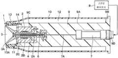
도 1은 제1 실시예에 의한 회전 무화 헤드형 도장 장치를 나타낸 종단면도이다.1 is a longitudinal sectional view showing a rotating atomizing head type coating apparatus according to the first embodiment.
도 2는 도 1의 분무기의 주위를 확대하여 나타낸 종단면도이다.2 is an enlarged longitudinal sectional view showing the periphery of the sprayer of FIG. 1.
도 3은 제1 변형예에 의한 회전 무화 헤드형 도장 장치를 나타낸 종단면도이다.3 is a longitudinal sectional view showing the rotating atomizing head type coating device according to the first modification.
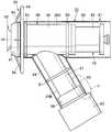
도 4는 제2 실시예에 의한 회전 무화 헤드형 도장 장치를 나타낸 정면도이다.Fig. 4 is a front view showing the rotating atomizing head coating device according to the second embodiment.
도 5는 도 4의 도장기를 커버 부재를 파단한 상태에서 확대하여 나타낸 정면도이다.FIG. 5 is an enlarged front view of the sprayer of FIG. 4 in a state where the cover member is broken. FIG.
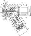
도 6은 도 4의 도장기를 나타낸 종단면도이다.6 is a longitudinal sectional view showing the sprayer of FIG.
도 7은 제2 실시예에 의한 도장기를 나타낸 도 5의 좌측면도이다.Fig. 7 is a left side view of Fig. 5 showing the sprayer according to the second embodiment.
도 8은 제3 실시예에 의한 회전 무화 헤드형 도장 장치를 나타낸 도 5와 마찬가지의 정면도이다.FIG. 8 is a front view similar to FIG. 5 showing the rotating atomizing head type coating apparatus according to the third embodiment.
도 9는 도 8의 a부를 확대하여 나타낸 주요부 확대 정면도이다.FIG. 9 is an enlarged front view of a main part of a part enlarged in FIG. 8;
도 10은 제2 변형예에 의한 넥크부측 커버를 나타낸 도 9와 마찬가지의 주요부 확대 정면도이다.It is a principal part enlarged front view similar to FIG. 9 which shows the neck part side cover by a 2nd modified example.
도 11은 제4 실시예에 의한 회전 무화 헤드형 도장 장치를 나타낸 도 5와 마찬가지의 정면도이다.FIG. 11 is a front view similar to FIG. 5 showing the rotary atomizing head coating device according to the fourth embodiment.
도 12는 제3 변형예에 의한 회전 무화 헤드형 도장 장치를 나타낸 도 5와 마찬가지의 정면도이다.FIG. 12 is a front view similar to FIG. 5 showing the rotary atomizing head coating device according to the third modification.
도 13은 제5 실시예에 의한 회전 무화 헤드형 도장 장치를 나타낸 도 5와 마찬가지의 정면도이다.FIG. 13 is a front view similar to FIG. 5 showing the rotary atomizing head coating device according to the fifth embodiment.
도 14는 제6 실시예에 의한 회전 무화 헤드형 도장 장치를 나타낸 종단면도이다.14 is a longitudinal sectional view showing the rotating atomizing head type coating device according to the sixth embodiment.
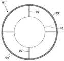
도 15는 제6 실시예에 의한 고전압 방전 전극을 도 14의 화살표 XV- XV 방향으로부터 본 우측면도이다.FIG. 15 is a right side view of the high voltage discharge electrode according to the sixth embodiment as seen from the arrow XV-XV direction in FIG. 14.
도 16은 제4 변형예에 의한 회전 무화 헤드형 도장 장치를 나타낸 종단면도이다.It is a longitudinal cross-sectional view which shows the rotating atomizing head type | mold coating apparatus by a 4th modified example.
도 17은 제4 변형예에 의한 고전압 방전 전극을 도 16의 화살표 XVII-XVII 방향으로부터 본 우측면도이다.17 is a right side view of the high voltage discharge electrode according to the fourth modification, seen from the direction of arrows XVII-XVII in FIG. 16.
도 18은 제7 실시예에 의한 회전 무화 헤드형 도장 장치를 커버 부재 등을 파단한 상태에서 나타낸 정면도이다.18 is a front view showing the rotating atomizing head coating device according to the seventh embodiment in a state where a cover member or the like is broken.
도 19는 제8 실시예에 의한 회전 무화 헤드형 도장 장치를 커버 부재 등을 파단한 상태에서 나타낸 정면도이다.Fig. 19 is a front view showing the rotating atomizing head type coating apparatus according to the eighth embodiment in a state where a cover member or the like is broken.
도 20은 제5의 변형예에 의한 회전 무화 헤드형 도장 장치를 커버 부재 등을 파단한 상태에서 나타낸 도 19와 마찬가지의 정면도이다.FIG. 20 is a front view similar to FIG. 19 showing the rotating atomizing head type coating apparatus according to the fifth modified example in a state where a cover member or the like is broken.
이하, 본 발명의 실시예에 의한 정전 도장 장치로서의 회전 무화 헤드형 도장 장치를 예로 들어 첨부한 도면에 따라서 설명한다.EMBODIMENT OF THE INVENTION Hereinafter, the rotating atomizing head type coating apparatus as an electrostatic coating apparatus by an Example of this invention is demonstrated according to attached drawing as an example.
먼저, 도 1 및 도 2는 제1 실시예를 나타낸다. 도면에 있어서의, 참조부호 1은 어스 전위에 있는 피도장물(도시하지 않음)에 향해 도료를 분무하는 도료 분무 수단으로서의 분무기를 나타낸다. 상기 분무기(1)는 후술하는 에어 모터(2), 회전 무화 헤드(3) 등으로 구성된다.First, FIG. 1 and FIG. 2 show the first embodiment. In the drawings,
참조부호 2는 도전성 금속 재료로 이루어지는 에어 모터를 나타낸다. 상기 에어 모터(2)는, 모터 하우징(2A)과, 상기 모터 하우징(2A) 내에 정압 에어 베어링(2B)을 통하여 회전 가능하게 지지된 중공의 회전축(2C)과, 상기 회전축(2C)의 기단 측에 고정된 에어 터빈(2D)으로 구성된다. 그리고, 에어 모터(2)는 에어 터빈(2D)에 구동 에어를 공급함으로써, 회전축(2C)과 회전 무화 헤드(3)를, 예를 들면 3000rpm ~ 100000rpm으로 고속 회전시킨다.
참조부호 3은 에어 모터(2)의 회전축(2C) 선단측에 장착된 회전 무화 헤드를 나타낸다. 상기 회전 무화 헤드(3)는, 예를 들면 금속 재료 또는 도전성의 수지 재료로 형성된다. 그리고, 회전 무화 헤드(3)는, 에어 모터(2)에 의해 고속 회전된 상태에서 후술하는 공급 튜브(feed tube)(4)를 통해서 도료를 공급함으로써, 상기 도료를 원심력에 의해 선단측의 방출 단부 에지(3A)로부터 분무한다. 또, 회전 무화 헤드(3)는 에어 모터(2) 등을 통하여 후술하는 고전압 발생기(7)에 접속되어 있다. 이로써, 정전 도장을 행하는 경우에, 회전 무화 헤드(3) 전체에 고전압을 인가할 수 있고, 이들 표면을 흐르는 도료를 직접적으로 고전압으로 대전시킬 수 있다.
참조부호 4는 회전축(2C) 내에 삽입되어 설치된 공급 튜브를 나타낸다. 상기 공급 튜브(4)의 선단측은, 회전축(2C)의 선단으로부터 돌출되어 회전 무화 헤드(3) 내에 연장된다. 또한, 공급 튜브(4) 내에는 도료 통로(5)가 형성되는 동시에, 상기 도료 통로(5)는 색 교환 밸브 장치 등을 통하여 도료 공급원 및 세정 신나 공급원(모두 도시하지 않음)에 접속되어 있다. 또, 공급 튜브의 중간 부위에는 후술하는 밸브체(6A)가 이격되어 착석되는 밸브 시트(4A)가 형성되어 있다. 이로써, 공급 튜브(4)는, 도장시에는 도료 통로(5)를 통해서 회전 무화 헤드(3)를 향해 도료 공급원으로부터의 도료를 공급하는 동시에, 세정시, 색 교환시 등에는 세정 신나 공급원으로부터의 세정 유체(신나, 공기 등)를 공급한다.
그리고, 공급 튜브(4)는 본 실시예에 한정되지 않고, 예를 들면 내통에 도료 통로가 형성되고, 외통에 세정 신나 통로가 배치된 이중 통형으로 형성해도 된다. 또, 도료 통로(5)는 본 실시예와 같이 공급 튜브(4) 내를 통과하는 것에 한정되지 않고, 분무기(1)의 종류에 따라 각종 통로 형태가 채용될 수 있다.In addition, the
참조부호 6은 도료 통로(5)의 중간에 설치된, 예를 들면 상시 밀폐형의 도료 공급 밸브를 나타낸다. 상기 도료 공급 밸브(6)는, 도료 통로(5) 내로 연장되어 선단이 밸브 시트(4A)에 이격되어 착석되는 밸브체(6A)와, 상기 밸브체(6A)의 기단 측에 위치되어 실린더(6B) 내에 설치된 피스톤(6C)과, 실린더(6B) 내에 설치되어 밸브체(6A)를 닫힘 방향으로 가압하는 밸브 스프링(6D)과, 실린더(6B) 내에서 밸브 스프링(6D)과 반대측에 설치된 수압실(6E)로 구성되어 있다. 그리고, 도료 공급 밸브(6)는, 수압실(6E)에 공급 밸브 구동 에어(파일럿 에어)가 공급됨으로써, 밸브 스프링(6D)에 저항하여 밸브체(6A)가 열리고, 도료 통로(5) 내의 도료의 유통을 허가한다.
참조부호 7은 에어 모터(2)에 접속된 고전압 인가 수단으로서의 고전압 발생기를 나타낸다. 상기 고전압 발생기(7)는 복수개의 콘덴서, 다이오드(모두 도시하지 않음)로 이루어지는 다단식 정류회로(이른바, 콕 크러프트(Cock croft) 회로)로 구성되어 있다. 또, 고전압 발생기(7)는, 고전압 제어 장치(8)로부터 공급되는 직류의 전원 전압을 승압하여, 예를 들면 -30kV ~ -150kV의 고전압을 발생한다. 이때, 고전압 발생기(7)는, 고전압 제어 장치(8)에 의한 전원 전압에 따라 발생하는 고전압이 설정되므로, 고전압 제어 장치(8)에 의해 출력 전압(고전압)이 제어되고 있다. 그리고 고전압 발생기(7)는 고전압 케이블(7A)을 통하여 에어 모터(2) 및 회전 무화 헤드(3)에 접속되고, 상기 회전 무화 헤드(3)에 의해 도료를 직접적으로 고전압으로 대전시키고 있다.
참조부호 9는 에어 모터(2)와 고전압 발생기(7)가 장착된 하우징 부재이다. 상기 하우징 부재(9)는, 예를 들면 POM(폴리옥시메틸렌), PET(폴리에틸렌 테레프탈레이트), PEN(폴리에틸렌 나프탈레이트), PP(폴리프로필렌), HP-PE(고압 폴리에틸렌), HP-PVC(고압 염화 피닐), PEI(폴리에테르이미드), PES(폴리에테르술폰), 폴리메틸펜텐 등의 절연성 수지 재료에 의해 대략 원기둥형으로 형성되어 있다.
그리고, 하우징 부재(9)는, 원통형의 외표면(9A)을 가지는 동시에, 상기 하우징 부재(9)의 후단(9B)은 대직경의 칼라형으로 형성되어 있다. 또한, 하우징 부재(9)의 앞쪽에는 에어 모터(2)를 수용하는 에어 모터 수용구멍(9C)이 형성되는 동시에, 하우징 부재(9)의 뒤쪽에는 고전압 발생기(7)를 수용하는 고전압 발생기 수용구멍(9D)이 형성되어 있다.The
참조부호 10은 하우징 부재(9)의 외표면(9A)과 간극을 가지고 설치된 통형의 커버 부재이다. 그리고, 커버 부재(10)는, 고절연성, 비흡수성을 가지는 절연성 수지 재료로서, 예를 들면 PTFE(폴리테트라플루오로에틸렌), P0M(폴리옥시메틸렌) 또는 표면 발수 처리를 행한 PET(폴리에틸렌테레프탈레이트) 등을 사용하여 형성되어 있다. 또, 커버 부재(10)는, 기계적 강도를 유지하기 위해, 예를 들면 0.1mm ~ 5mm 정도의 두께 치수를 가지고 통형으로 형성되어 있다. 또한, 커버 부재(10)의 전단 측에는, 내주측을 향해 환형으로 돌출되고, 하우징 부재(9)의 전단측을 폐색하는 전방 폐색 부재(11)가 형성되어 있다.
여기서, 커버 부재(10)는, 후단측이 하우징 부재(9)의 대직경인 후단(9B)에 장착되고, 전단측이 전방 폐색 부재(11)에 장착되어 있다. 그러나, 커버 부재(10)와 하우징 부재(9)가 서로 직경 방향으로 대면하는 부위(커버 부재(10)의 축 방향 중간 부위)는, 대략 전체면에 걸쳐 하우징 부재(9)와 이격되어 있다. 이 결과, 커버 부재(10)와 하우징 부재(9) 사이에는 횡단면이 환형인 환형 공간(12)이 형성되어 있다. 이로써, 환형 공간(12)은, 에어 모터(2) 및 고전압 발생기(7)의 외주측을 대략 전체면에 걸쳐 둘러싸고 있다. 그리고, 환형 공간(12)은, 커버 부재(10)로부터 하우징 부재(9)로 향하는 누설 전류를 방지하기 위해, 커버 부재(10)와 하우징 부재(9)의 사이에, 예를 들면 5mm 이상의 간격 치수를 갖고 형성되어 있다.Here, the
참조부호 13은 셰이핑 에어를 분출하는 셰이핑 에어링을 나타낸다. 상기 셰이핑 에어링(13)은, 회전 분무 헤드(3)의 외주측을 덮도록 커버 부재(10)의 선단측(전단측)에 전방 폐색 부재(11)를 개재하여 설치되어 있다. 그리고, 셰이핑 에어링(13)은, 커버 부재(10)와 대략 동일한 부재로서, 예를 들면 PTFE, POM 또는 표면 발수 처리를 행한 PET 등을 사용하여 통형으로 형성되어 있다. 또, 셰이핑 에어링(13)에는 복수개의 에어 토출구멍(13A)이 형성되고, 상기 에어 토출구멍(13A)은 하우징 부재(9) 내에 형성된 셰이핑 에어 통로(14)에 연통되어 있다. 그리고, 에어 토출구멍(13A)에는 셰이핑 에어 통로(14)를 통하여 셰이핑 에어가 공급되고, 에어 토출구멍(13A)은, 상기 셰이핑 에어를 회전 무화 헤드(3)로부터 분무되는 도료를 향해 분출한다. 이로써, 셰이핑 에어는 회전 무화 헤드(3)로부터 분무된 도료 입자의 분무 패턴을 정형(整形)한다.
제1 실시예에 의한 회전 무화 헤드형 도장 장치는 전술한 바와 같은 구성을 가짐으로써, 다음에, 상기 도장 장치를 사용한 도장 동작에 대하여 설명한다.The rotating atomizing head type coating device according to the first embodiment has the configuration as described above. Next, the painting operation using the coating device will be described.
분무기(1)는, 에어 모터(2)에 의해 회전 무화 헤드(3)를 고속 회전시키고, 이 상태에서 공급 튜브(4)를 통해서 회전 무화 헤드(3)에 도료를 공급한다. 이로써, 분무기(1)는, 회전 무화 헤드(3)가 회전될 때의 원심력에 의해 도료를 미립화해, 도료 입자로서 분무한다. 또, 셰이핑 에어링(13)으로부터 셰이핑 에어가 공급되고, 상기 셰이핑 에어에 의해 도료 입자로 이루어지는 분무 패턴이 제어된다.The
또한, 회전 무화 헤드(3)에는 에어 모터(2)를 통하여 고전압 발생기(7)에 의한 고전압이 인가되어 있다. 이로써, 회전 무화 헤드(3)에 공급된 도료는, 회전 무화 헤드(3)를 통해서 직접적으로 고전압으로 대전되는 동시에, 대전 도료 입자로 되어 회전 무화 헤드(3)와 피도장물 사이에 형성된 정전계를 따라 비행하고, 피도장물에 도착된다.Moreover, the high voltage by the
그런데, 일반적으로 공기의 체적 저항율을 무한대로 가정할 수 있는 것에 대해, 각종의 절연성 수지 재료(유전체 재료)에 의해 형성되는 하우징 부재(9)의 체적 저항율은 1012Ωm ~ 1016Ωm 정도이다. 그러므로, 하우징 부재(9)의 전기 저항은, 공기의 전기 저항에 비해 낮다.By the way, while the volume resistivity of air can be assumed to be infinite, the volume resistivity of the
이에 대해, 제1 실시예에서는, 하우징 부재(9)와 커버 부재(10) 사이에는 이들 하우징 부재(9)와 커버 부재(10)가 서로 대면하는 부위의 전체면에 걸쳐 환형 공간(12)을 형성하는 구성으로 하고 있다. 그러므로, 공기에 비해 전기 저항이 낮은 하우징 부재(9)가 커버 부재(10)에 접촉되는 부위를 줄일 수 있다. 이로써, 고 전압으로 대전된 커버 부재(10)의 외표면의 전하가 하우징 부재(9)를 통하여 누설되는 것을 줄일 수 있으므로, 커버 부재(10)의 대전 상태를 유지하고, 대전 도료 입자의 부착을 방지할 수 있다.In contrast, in the first embodiment, the
또한, 제1 실시예에서는, 분무기(1)가 에어 모터(2)와 회전 무화 헤드(3)로 구성되어 있다. 이때, 회전 무화 헤드(3)로부터 하우징 부재(9)의 외주측에 대전 도료 입자가 방출되어, 하우징 부재(9)의 주위를 부유(浮遊)하는 경향이 있다. 또, 자동차의 차내와 같이 닫힌 공간을 도장할 때는, 부유된 대전 도료 입자가 하우징 부재(9) 측에 가까워져, 부착되기 쉬운 경향이 있다. 이것에 대해, 본 실시예에서는, 환형 공간(12)에 의해 커버 부재(10)의 대전 상태를 유지할 수 있으므로, 커버 부재(10)의 전하에 의해 부유된 대전 도료 입자에 대해서 쿨롱 반발력을 작용시킬 수 있고, 분무기(1)를 덮는 커버 부재(10)에 도료 입자가 부착되는 것을 억제할 수 있다.In addition, in the first embodiment, the
또한, 고전압 발생기(7)는 에어 모터(2)에 고전압을 인가하는 구성으로 하고 있다. 그러므로, 에어 모터(2)에 의해 커버 부재(10)의 외표면에 고전압을 안정적으로 대전시킬 수 있고, 도료 입자가 부착되는 것을 방지할 수 있다.In addition, the
그리고, 상기 제1 실시예에서는, 커버 부재(10)와 셰이핑 에어링(13)은 별도의 부재에 의해 형성되는 것으로 하였다. 그러나, 본 발명은 이에 한정되지 않고, 예를 들면 도 3에 나타낸 제1 변형예와 같이, 커버 부재(10')와 셰이핑 에어링(13')을 일체화시켜 형성해도 된다.In the first embodiment, the
또, 제1 실시예에서는, 셰이핑 에어링(13)은 절연 수지 재료를 사용하여 형 성하는 것으로 하였다. 그러나, 본 발명은 이에 한정되지 않고, 예를 들면 셰이핑 에어링을 도전성 금속 재료를 사용하여 형성해도 된다. 이 경우, 금속 재료로 이루어지는 셰이핑 에어링에는, 에어 모터를 통하여 도료와 동일한 극성의 고전압이 인가된다. 이로써, 셰이핑 에어링은 반발 전극으로서 기능하기 때문에, 셰이핑 에어링에 대전 도료 입자가 부착되는 것을 방지할 수 있다.In the first embodiment, the shaping
다음에, 도 4 내지 도 7은 제2 실시예에 의한 회전 무화 헤드형 도장 장치를 나타낸다. 제2 실시예의 특징은, 하우징 부재가 전,후 방향으로 연장해 앞쪽에 도료 분무 수단을 지지하는 보디부와, 상기 보디부로부터 분기된 넥크부에 의해 구성되고, 커버 부재가 하우징 부재의 보디부를 덮는 보디부측 커버와, 상기 하우징 부재의 넥크부를 덮는 넥크부측 커버로 구성되어 있다.4 to 7 show the rotary atomizing head type coating apparatus according to the second embodiment. A feature of the second embodiment is that the housing member is constituted by a body portion extending forward and backward to support the paint spraying means, and a neck portion branched from the body portion, and the cover member covers the body portion of the housing member. The body part side cover and the neck part side cover which cover the neck part of the said housing member are comprised.
도면에서, 참조부호 21은 자동 도장 작업을 행하기 위한 로봇 장치를 나타낸다. 상기 로봇 장치(21)는, 후술하는 도장기(31)를 사용한 도장 작업을 실행하는 것이다. 그리고, 로봇 장치(21)는 기대(22)와, 상기 기대(22) 상에 회전 가능하고 요동 가능하게 설치되어 복수개의 관절을 가진 로봇 암(23)(arm)으로 대략 구성되어 있다. 그리고, 로봇 장치(21)는 도장기(31)를 피도장물(A)에 대해서 이동시키는 동시에, 어스에 접속되어 있다.In the figure,
참조부호 31은 로봇 장치(21)에 장착된 카트리지식 도장기를 나타낸다. 상기 도장기(31)는, 후술하는 분무기(32), 하우징 부재(35), 카트리지(42) 등으로 대략 구성되어 있다.
참조부호 32는 어스 전위에 있는 피도장물(A)을 향해 도료를 분무하는 도료 분무 수단으로서의 분무기를 나타낸다. 상기 분무기(32)는 후술하는 에어 모터(33), 회전 무화 헤드(34) 등으로 구성되어 있다.
참조부호 33은 도전성 금속 재료로 이루어지는 에어 모터를 나타낸다. 상기 에어 모터(33)는, 모터 하우징(33A)과, 상기 모터 하우징(33A) 내에 정압 에어 베어링(33B)을 통하여 회전 가능하게 지지된 중공의 회전축(33C)과, 상기 회전축(33C)의 기단 측에 고정된 에어 터빈(33D)으로 구성되어 있다. 그리고, 에어 모터(33)는, 후술하는 에어 통로(39)를 통해서 구동 에어를 에어 터빈(33D)에 공급함으로써, 회전축(33C)과 회전 무화 헤드(34)를, 예를 들면 3000rpm ~ 100000rpm으로 고속 회전시키는 것이다.
참조부호 34는 에어 모터(33)의 회전축(33C) 선단측에 장착된 회전 무화 헤드를 나타낸다. 상기 회전 무화 헤드(34)는, 예를 들면 금속 재료 또는 도전성 수지 재료로 형성되어 있다. 그리고, 회전 무화 헤드(34)는, 에어 모터(33)에 의해 고속 회전된 상태에서 후술하는 공급 튜브(44)를 통해서 도료를 공급함으로써, 상기 도료를 원심력에 의해 선단측의 방출 단부 에지(34A)로부터 분무한다. 또한, 회전 무화 헤드(34)에는 에어 모터(33) 등을 통하여 후술하는 고전압 발생기(45)가 접속되어 있다. 이로써, 정전 도장을 행하는 경우에, 회전 무화 헤드(34) 전체에 고전압을 인가할 수 있고, 이들 표면을 흐르는 도료를 직접적으로 고전압으로 대전시킬 수 있다.
참조부호 35는 에어 모터(33) 등을 지지하는 하우징 부재를 나타낸다. 상기 하우징 부재(35)는, 제1 실시예에 의한 하우징 부재(9)와 마찬가지로, 예를 들면 POM(폴리옥시메틸렌), PET(폴리에틸렌 테레프탈레이트), PEN(폴리에틸렌나프탈레이트), PP(폴리프로필렌), HP-PE(고압 폴리에틸렌), HP-PVC(고압 염화 비닐), PEI(폴리에테르이미드), PES(폴리에테르술폰), 폴리메틸펜텐 등의 절연성 수지 재료에 의해 구성되어 있다.
또, 하우징 부재(35)는, 축 방향(전,후 방향)에 연신된 원기둥형의 보디부(36)와, 상기 보디부(36)의 축 방향의 중간 위치로부터 외주측을 향해 경사지게 분기된 넥크부(37)로 구성되어 있다.In addition, the
그리고, 보디부(36)의 앞쪽에는, 에어 모터(33)를 수용하는 에어 모터 수용구멍(36A)이 형성되는 동시에, 보디부(36)의 뒤쪽에는, 후술하는 카트리지(42)의 봄베(43)를 장착하기 위한 봄베 장착부(36B)가 형성되어 있다. 또, 보디부(36) 내에는, 에어 모터 수용구멍(36A)과 봄베 장착부(36B)의 중심 위치를 통과하는 공급 튜브 삽입구멍(36C)이 축방향으로 연장되어 형성되어 있다.And the air motor
한편, 넥크부(37) 내에는, 후술하는 고전압 발생기(45)를 수용하는 고전압 발생기 수용구멍(37A)이 형성되어 있다. 그리고, 넥크부(37)의 선단은, 절연성 수지 재료로 이루어지는 통형의 커넥터 부재(38)를 사용하여 로봇 장치(21)의 로봇 암(23)의 선단에 장착되어 있다. 또한, 하우징 부재(35) 내에는, 에어 모터(33)에 구동 에어를 공급하는 에어 통로(39)가 형성되는 동시에, 후술하는 카트리지(42)에 도료 토출량 제어용 압출 액체를 공급하는 압출 액체 통로(4O)가 형성되어 있다.On the other hand, in the
참조부호 41은 회전 무화 헤드(34)를 둘러싸도록 하우징 부재(35)의 보디부(36)의 전단 측에 설치된 셰이핑 에어링을 나타낸다. 상기 셰이핑 에어링(41) 은, 예를 들면 도전성 금속 재료를 사용하여 형성되고, 에어 모터(33)에 전기적으로 접속되어 있다. 또, 셰이핑 에어링(41)에는 복수개의 에어 토출구멍(41A)이 형성되고, 상기 에어 토출구멍(41A)은 회전 무화 헤드(34)로부터 분무되는 도료를 향해 셰이핑 에어를 분출한다.
참조부호 42는 도료를 회전 무화 헤드(34)를 향해 공급하는 도장용의 카트리지를 나타낸다. 상기 카트리지(42)는, 축 방향(전,후 방향)으로 연장되는 원통체(실린더)로서 형성된 봄베(43)와, 상기 봄베(43)로부터 축방향으로 연장되는 공급 튜브(44)와, 상기 봄베(43) 내를 도료 수용실과 압출 액체 수용실로 구획하는 피스톤(모두 도시하지 않음) 등으로 대략 구성되어 있다.
또, 카트리지(42)는, 공급 튜브(44)를 공급 튜브 삽입구멍(36C)에 삽입한 상태에서 하우징 부재(35)의 봄베 장착부(36B)에 장착된다. 그리고, 도장시에는, 하우징 부재(35)의 압출 액체 통로(4O)를 통해서 압출 액체 수용실에 압출 액체를 공급함으로써, 피스톤을 슬라이드 이동시켜, 봄베(43) 내의 도료를, 공급 튜브(44)를 통해서 회전 무화 헤드(34)를 향해 토출한다. 또, 도료의 충전시에는, 카트리지(42)를 봄베 장착부(36B)로부터 분해하여 도료 충전 장치(도시하지 않음)에 장착하고, 공급 튜브(44)를 통해서 봄베(43)의 도료 수용실 내에 도료를 충전한다.Moreover, the
참조부호 45는 하우징 부재(35)의 넥크부(37)에 내장된 고전압 인가 수단으로서의 고전압 발생기를 나타낸다. 상기 고전압 발생기(45)는 입력측이 로봇 장치(21)를 통하여 외부의 고전압 제어 장치(46)에 접속되고, 출력측이 에어 모터(33)에 접속되어 있다. 그리고, 고전압 발생기(45)는, 예를 들면 복수개의 콘덴 서, 다이오드(모두 도시하지 않음)로 이루어지는 다단식 정류회로(이른바, 콕 크러프트 회로)로 구성되어 있다.
또한, 고전압 발생기(45)는, 고전압 제어 장치(46)로부터 공급되는 직류의 전원 전압을 승압하여, 예를 들면 -30kV ~ -150kV의 고전압을 발생한다. 이때, 고전압 발생기(45)는, 고전압 제어 장치(46)에 의한 전원 전압에 따라 발생되는 고전압이 설정되므로, 고전압 제어 장치(46)에 의해 출력 전압(고전압)이 제어되고 있다. 그리고, 고전압 발생기(45)는 고전압 케이블(45A)을 통하여 에어 모터(33) 및 회전 무화 헤드(34)를 통해서 도료를 직접적으로 고전압으로 대전시키고 있다.In addition, the
참조부호 47은 하우징 부재(35)의 외표면을 덮도록 설치된 커버 부재를 나타낸다. 상기 커버 부재(47)는 고절연성, 비흡수성을 가지는 불소계의 절연 수지로서, 예를 들면 PTFE(폴리테트라플루오로에틸렌), ETFE(에틸렌과 테트라플루오로에틸렌의 공중합체) 등으로 이루어지는 불소계 수지 필름 부재를 사용하여 형성되어 있다. 또, 커버 부재(47)는, 보디부(36)의 외표면(36D)을 둘러싸는 보디부측 커버(48)와, 넥크부(37)의 외표면(37B)을 둘러싸는 넥크부측 커버(49)로 구성되어 있다. 그리고, 각 커버(48, 49)는, 예를 들면 0.1mm ~ 5mm 정도의 두께 치수를 가진 수지 필름 부재를 둥글게 해 각각 통형으로 형성되어 있다.
여기서, 보디부측 커버(48)는, 보디부(36)의 주위로부터 후방을 향해 연신되어 있다. 이로써, 보디부측 커버(48)는, 보디부(36)의 외표면(36D)을 덮는 동시에, 카트리지(42)의 봄베(43)의 외표면도 덮고 있다. 또, 보디부측 커버(48)는, 보디부(36)의 전,후 방향의 양단 측에 형성된 원환형의 칼라부(5O)에 장착되어 있 다. 한편, 넥크부측 커버(49)는 넥크부(3) 중 길이 방향의 도중 위치에 형성된 원환형의 칼라부(51) 선단 위치에 설치된 커넥터 부재(3)이다.Here, the body part side cover 48 is extended toward the rear from the circumference of the
그리고, 보디부측 커버(48) 중 보디부(36)의 외표면(36D)과 서로 대면하는 부위는, 칼라부(50)와 접촉되는 근소한 부위를 제외하고 대략 전체면에 걸쳐 보디부(36)와 이격되어 있다. 또한, 커버 부재(47)의 넥크부측 커버(49) 중 넥크부(37)의 외표면(37B)과 서로 대면하는 부위는, 칼라부(51), 커넥터 부재(38)와 접촉되는 근소한 부위를 제외하고 거의 전체면에 걸쳐 넥크부(37)와 이격되어 있다.And the part of the
이로써, 보디부(36)와 보디부측 커버(48) 사이에는, 횡단면이 환형인 환형 공간(52)이 형성되는 동시에, 넥크부(37)와 넥크부측 커버(49) 사이에, 횡단면이 환형인 환형 공간(52)이 형성되어 있다. 그러므로, 커버 부재(47)와 하우징 부재(35) 사이에는, 대략 전체면에 걸쳐 환형 공간(52)이 형성되어 있다. 이 결과, 환형 공간(52)은, 에어 모터(33) 및 고전압 발생기(45)의 외주측을 대략 전체면에 걸쳐 둘러싸고 있다. 그리고, 환형 공간(52)은, 커버 부재(47)로부터 하우징 부재(35)를 향하는 누설 전류를 방지하기 위해, 커버 부재(47)와 하우징 부재(35) 사이에, 예를 들면 5mm 이상의 간격 치수를 가지고 형성되어 있다.As a result, an
참조부호 53은 보디부측 커버(48)의 외주측에 설치된 고전압 방전 전극을 나타낸다. 상기 고전압 방전 전극(53)은 도전성 재료를 사용하여 형성되고, 후술하는 지지 가로대(54), 링부(55)로 구성되어 있다.
참조부호 54는 셰이핑 에어링(41)의 주위에 방사상으로 설치된 지지 가로대를 나타낸다. 상기 지지 가로대(54)는, 하우징 부재(35) 측으로부터 보디부측 커 버(48)의 외주측을 향해 직경 방향을 따라 연신되어 있다. 그리고, 지지 가로대(54)는, 셰이핑 에어링(41)의 주위에 동일한 간격으로, 예를 들면 4개 설치되고, 링부(55)를 지지하고 있다.
참조부호 55는 지지 가로대(54)의 선단에 설치된 링부를 나타낸다. 상기 링부(55)는, 예를 들면 금속 등의 도전성 재료를 사용하여 원환형으로 형성되어 있다. 또한, 링부(55)는 에어 모터(33)의 주위에 위치되어 보디부측 커버(48)의 앞쪽을 둘러싸고 있다. 그리고, 링부(55)는 보디부측 커버(48)의 외경보다 큰 원형으로 형성되고, 에어 모터(33)의 회전축(33C)과 동축의 대략 동심원형으로 배치되어 있다. 이로써, 링부(55)는 그 전체 원주에 걸쳐 보디부측 커버(48)와의 거리가 대략 일정하게 되어 있다. 그리고, 링부(55)는 지지 가로대(54), 셰이핑 에어링(41)을 통하여 에어 모터(33)에 접속되어 있다. 이로써, 링부(55)에는 고전압 발생기(45)에 의한 고전압이 인가되고, 링부(55)는 대전 도료 입자와 동일한 극성의 이온을 방전한다.
제2 실시예에 의한 회전 무화 헤드형 도장 장치는 전술한 바와 같은 구성을 가지는 것으로, 다음에, 도장 장치로서의 작동에 대하여 설명한다.The rotary atomizing head type coating apparatus according to the second embodiment has the configuration as described above, and the operation as the coating apparatus will next be described.
컨베이어 장치 등을 사용하여 피도장물(A)이 로봇 장치(21)의 근방에 배치되면, 로봇 장치(21)는, 미리 기억된 티칭(teaching) 동작에 따라 플레이백 동작되고, 피도장물(A)의 가까이에 도장기(31)를 이동시킨다.When the workpiece A is placed in the vicinity of the
이때, 도장기(31)는 에어 모터(33)에 의해 회전 무화 헤드(34)를 고속 회전시키고, 이 상태에서 봄베(43) 내의 도료를 공급 튜브(44)를 통해서 회전 무화 헤 드(34)를 향해 공급한다. 이로써, 도장기(31)는, 회전 무화 헤드(34)가 회전될 때의 원심력에 의해 도료를 미립화하고, 도료 입자로서 분무한다. 또, 셰이핑 에어링(41)으로부터 셰이핑 에어가 공급되고, 상기 셰이핑 에어에 의해 도료 입자로 이루어지는 분무 패턴이 제어된다.At this time, the
또한, 회전 무화 헤드(34)에는 에어 모터(33)를 통하여 고전압 발생기(45)에 의해 고전압이 인가되어 있다. 이로써, 회전 무화 헤드(34)에 공급된 도료는, 회전 무화 헤드(34)를 통해서 직접적으로 고전압으로 대전하는 동시에, 대전 도료 입자로 되어 회전 무화 헤드(34)와 피도장물(A) 사이에 형성된 정전계를 따라 비행하고, 어스 전위가 된 피도장물(A)에 도착된다.In addition, a high voltage is applied to the
또한, 제2 실시예에서는, 보디부측 커버(48)의 외주측에는 고전압 방전 전극(53)을 설치하는 구성으로 하고 있다. 그러므로, 고전압 발생기(45)로부터의 고전압은, 에어 모터(33) 등을 통하여 링부(55)에 인가되어, 링부(55)로부터 방전된다.In the second embodiment, the high
이로써, 고전압 방전 전극(53)은, 대전 도료 입자와 동일한 극성의 이온을 방전하고, 커버 부재(47)에 대해서 동일한 극성의 전하를 적극적으로 대전시킬 수 있다. 또한, 고전압 방전 전극(53)은, 링부(55)의 방전에 의해, 대전량이 감쇠된 도료 입자에 대해서 재차 대전될 수 있다. 이 결과, 재차 대전된 도료 입자와 고전압 방전 전극(53) 또는 커버 부재(47) 사이에서 반발력을 작용시킬 수 있고, 커버 부재(47)에 도료 입자가 부착되는 것을 확실하게 방지할 수 있다.As a result, the high
따라서, 제2 실시예에서는, 하우징 부재(35)와 커버 부재(47) 사이에는 이들 하우징 부재(35)와 커버 부재(47)가 서로 대면하는 부위의 대략 전체면에 걸쳐 환형 공간(52)을 형성하는 구성으로 하고 있다.Therefore, in the second embodiment, the
일반적으로 공기의 체적 저항율을 무한대로 가정할 수 있는 것에 대해, 각종의 절연성 수지 재료(유전체 재료)로 형성되는 하우징 부재(35)의 체적 저항율은 1012Ωm ~ 1016Ωm 정도이다. 그러므로, 하우징 부재(35)의 전기 저항은, 공기의 전기 저항에 비해 낮다.In general, while the volume resistivity of air can be assumed to be infinite, the volume resistivity of the
이것에 대해, 하우징 부재(35)와 커버 부재(47) 사이에는 환형 공간(52)을 형성하였으므로, 상기 환형 공간(52)에 의해 하우징 부재(35)가 커버 부재(47)에 접촉되는 부위를 줄일 수 있다. 그러므로, 고전압으로 대전된 커버 부재(47)의 외표면의 전하가 하우징 부재(35)를 통하여 누설되는 것을 감소할 수 있으므로, 커버 부재(47)의 대전 상태를 유지하고, 대전 도료 입자의 부착을 방지할 수 있다.On the other hand, since the
또한, 본 실시예에서는, 도장 중에 회전 무화 헤드(34)로부터 분무된 일부의 대전 도료 입자는 커버 부재(47)의 외주측을 부유하는 경향이 있다. 그러나, 환형 공간(52)에 의해 커버 부재(47)의 대전 상태를 유지할 수 있으므로, 커버 부재(47)의 전하에 의해 부유된 대전 도료 입자에 대해서 쿨롱 반발력을 작용시킬 수 있고, 분무기(32)를 덮는 커버 부재(47)에 도료 입자가 부착되는 것을 억제할 수 있다.In addition, in the present embodiment, some of the charged paint particles sprayed from the
또한, 고전압 발생기(45)는 에어 모터(33), 회전 무화 헤드(34), 셰이핑 에어링(41) 등에 고전압을 인가하는 구성으로 하고 있다. 그러므로, 에어 모터(33) 등에 의해 커버 부재(47)의 외표면에 고전압을 안정적으로 대전시킬 수 있어, 도료 입자가 부착되는 것을 방지할 수 있다.The
특히, 제2 실시예에서는, 커버 부재(47)는, 하우징 부재(35)의 보디부(36)를 덮는 보디부측 커버(48)와, 하우징 부재(35)의 넥크부(37)를 덮는 넥크부측 커버(49)로 구성되므로, 보디부측 커버(48) 및 넥크부측 커버(49)를 사용하여 하우징 부재(35)의 외표면 전체를 덮을 수 있다. 이로써, 보디부측 커버(48) 및 넥크부측 커버(49)를 대전시켜 대전 도료 입자의 부착을 방지할 수 있다.In particular, in the second embodiment, the
또한, 커버 부재(47)를 불소계 수지 필름 부재를 사용하여 형성하였으므로, 예를 들면 발수성을 가지는 PTFE 등을 사용하여 커버 부재(47)를 형성할 수 있고, 발수 작용에 의해 커버 부재(47)에 대한 대전 도료 입자의 부착을 방지할 수 있다. 또한, 불소계 수지 필름 부재를 대전시킴으로써, 대전 도료 입자에 반발력을 작용시킬 수 있다. 또한, 불소계 수지 필름 부재는, 흡습성이 낮고, 체적 저항율이 높기 때문에, 이들에 대전된 전하가 누설되기 어렵다. 그러므로, 커버 부재(47)의 대전 상태를 안정적으로 유지할 수 있다.Moreover, since the
또한, 커버 부재(47)에 도료가 부착된 경우에는, 필름형의 커버 부재(47)를, 하우징 부재(35)로부터 용이하게 벗겨내, 교환할 수 있다. 이로써, 하우징 부재(35)를 세정하는 것에 비해, 도장기(31)의 유지 관리 시간을 단축할 수 있고, 도장 작업의 생산성을 높일 수 있다.In addition, when the coating material adheres to the
또한, 제2 실시예에서는, 보디부측 커버(48)의 외주측에는 고전압 방전 전극(53)을 설치하는 구성으로 하였으므로, 고전압 발생기(45)로부터의 고전압은, 에어 모터(33), 셰이핑 에어링(41) 등을 통하여 링부(55)에 인가되어 방전된다. 그 러므로, 고전압 방전 전극(53)은, 대전 도료 입자와 동일한 극성의 이온을 방전하고, 동일한 극성의 전하로 커버 부재(47)에 대해서 적극적으로 대전될 수 있다. 또한, 고전압 방전 전극(53)은, 링부(55)의 방전에 의해, 대전량이 감쇠된 도료 입자에 대해서 재차 대전될 수 있다.In the second embodiment, since the high
이 결과, 재차 대전된 도료 입자와 고전압 방전 전극(53) 또는 커버 부재(47) 사이에서 반발력을 작용시킬 수 있다. 그러므로, 상기 반발력에 의해 대전 도료 입자가 커버 부재(47)에 가까워지는 것을 방지할 수 있는 동시에, 고전압으로 대전된 커버 부재(47)에 의해 대전 도료 입자가 부착되는 것을 방지할 수 있다.As a result, the repulsive force can be exerted between the repainted paint particles and the high
또한, 고전압 방전 전극(53)을 지지 가로대(54) 및 링부(55)로 구성하였으므로, 보디부측 커버(48)를 둘러싸는 링부(55)에 의해 커버 부재(47)의 주위에 고전압의 정전계를 형성할 수 있고, 대전 도료 입자를 커버 부재(47)로부터 멀리할 수 있다. 또한, 링부(55)는 보디부측 커버(48)를 둘러싸기 때문에, 고전압 방전 전극(53)을 생략한 경우에 비해, 링부(55)에 의한 고전압의 방전에 의해 커버 부재(47)를 넓은 범위에서 고전압의 전하로 대전시킬 수 있다. 이로써, 커버 부재(47)의 넓은 범위에서 대전 도료 입자가 부착되는 것을 방지할 수 있다.In addition, since the high
다음에, 도 8 및 도 9는 제3 실시예에 의한 회전 무화 헤드형 도장 장치를 나타낸다. 제3 실시예의 특징은, 보디부측 커버는 불소계의 수지 재료로 이루어지는 불소계 수지 필름 부재를 사용하여 형성되고, 넥크부측 커버는 절연성을 가지는 2개의 절연 필름의 사이에 반 도전성을 가지는 반도전 필름을 끼운 적층 필름 부재를 사용하여 형성된 것에 있다. 그리고, 제3 실시예에서는 제2 실시예와 동일한 구성 요소에는 동일한 부호를 부여하고, 그 설명을 생략한다.8 and 9 show the rotary atomizing head type coating apparatus according to the third embodiment. The feature of the third embodiment is that the body portion side cover is formed using a fluorine resin film member made of a fluorine resin material, and the neck portion side cover is formed by sandwiching a semiconductive film having semiconductivity between two insulating films having insulation. It exists in what was formed using the laminated | multilayer film member. Incidentally, in the third embodiment, the same reference numerals are given to the same components as those in the second embodiment, and the description thereof is omitted.
참조부호 61은 하우징 부재(35)의 외표면을 덮어 설치한 커버 부재를 나타낸다. 상기 커버 부재(61)는, 보디부(36)의 외표면(36D) 및 봄베(43)의 외표면을 둘러싸는 보디부측 커버(62)와, 넥크부(37)의 외표면(37B)을 둘러싸는 넥크부측 커버(63)로 구성되어 있다.
여기서, 보디부측 커버(62)는, 제2 실시예에 의한 보디부측 커버(48)와 마찬가지로, 예를 들면, PTFE 등으로 이루어지는 불소계 수지 필름 부재를 사용하여 형성되어 있다.Here, the body part side cover 62 is formed using the fluorine resin film member which consists of PTFE etc. similarly to the body part side cover 48 which concerns on 2nd Example.
한편, 넥크부측 커버(63)는, 절연성을 가지는 2개의 절연 필름(63A, 63B)의 사이에 반 도전성을 가지는 반도전 필름(63C)을 끼운 적층 필름 부재로 형성되어 있다. 이때, 절연 필름(63A, 63B)은, 예를 들면 PTFE 등으로 이루어지는 불소계 수지를 사용하여 형성되고, 그 체적 저항율은, 예를 들면 1016Ωm 이상으로 설정되어 있다. 한편, 반도전 필름(63C)은, 절연 필름(63A, 63B)보다 저항이 낮은 재료로서, 예를 들면 체적 저항율이 1011Ωm 이하의 폴리에틸렌 등의 수지를 사용하여 형성되어 있다. 그리고, 이들 필름(63A, 63B, 63C)의 두께 치수는, 각각 예를 들면 0.10mm ~ 1.0mm 정도, 바람직하게는 0.10mm ~ 0.3mm 정도로 설정되어 있다.On the other hand, the neck part side cover 63 is formed with the laminated | multilayer film member which inserted the
여기서, 보디부측 커버(62)는, 보디부(36)의 전,후 방향의 양단 측에 형성된 칼라부(50)에 장착되어 있다. 또한, 넥크부측 커버(63)는, 넥크부(37)의 길이 방향의 중간 위치에 형성된 칼라부(51)와 넥크부(37)의 선단 위치에 설치된 커넥터 부재(38)에 장착되어 있다. 그리고, 보디부측 커버(62) 중 보디부(36)의 외표면(36D)과 서로 대면하는 부위는, 칼라부(50)와 접촉되는 근소한 부위를 제외하고 대략 전체면에 걸쳐 보디부(36)와 이격되어 있다.Here, the body part side cover 62 is attached to the
또한, 넥크부측 커버(63) 중 넥크부(37)의 외표면(37B)과 서로 대면하는 부위는, 칼라부(51), 커넥터 부재(38)와 접촉되는 근소한 부위를 제외하고 대략 전체면에 걸쳐 넥크부(37)와 이격되어 있다. 이로써, 커버 부재(61)와 하우징 부재(35) 사이에는, 제2 실시예에 의한 환형 공간(52)과 마찬가지로, 대략 전체면에 걸쳐 환형 공간(64)이 형성되어 있다. 이로써, 환형 공간(64)은, 에어 모터 및 고전압 발생기의 외주측을 대략 전체면에 걸쳐 둘러싸고 있다.In addition, the part of the neck part side cover 63 which faces the
또, 넥크부측 커버(63)의 선단부는, 넥크부(37)의 선단을 향해 연신되고, 로봇 암(23)에 접촉되어 있다. 그러나, 넥크부측 커버(63)의 선단부에서는, 반도전 필름(63C)을 제거함으로써, 반도전 필름(63C)과 로봇 암(23) 사이에 공간이 형성되어 있다. 즉, 도 9에 나타낸 바와 같이, 넥크부측 커버(63)의 절연 필름(63A, 63B)은 로봇 암(23)에 접촉되는 것에 대해, 반도전 필름(63C)은, 예를 들면 10mm 이상의 간격 치수(L)를 가지고 로봇 암(23)으로부터 이격되어 있다. 이로써, 넥크부측 커버(63)는, 반도전 필름(63C)에 대전된 전하가 어스체로 되는 로봇 암(23)을 향해 방전하는 것을 방지하고 있다.Moreover, the front end of the neck part side cover 63 is extended toward the front end of the
따라서, 제3 실시예에서도 제2 실시예와 마찬가지의 작용 효과를 얻을 수 있다. 특히, 제3 실시예에서는, 보디부측 커버(62)는 불소계 수지 필름 부재를 사용하여 형성되고, 넥크부측 커버(63)는 적층 필름 부재를 사용하여 형성되어 있다. 이때, 분무기(32), 셰이핑 에어링(41) 및 고전압 방전 전극(53)은, 고전압 발생기(45)에 의해 고전압이 인가되어 있다. 그러므로, 분무기(32) 등에 가까운 보디부측 커버(62)는 대전되기 쉽고, 보디부측 커버(62)에 대한 도료의 부착은 용이하게 억제될 수 있다.Therefore, the same effect as that of the second embodiment can also be obtained in the third embodiment. In particular, in the third embodiment, the body part side cover 62 is formed using a fluorine-based resin film member, and the neck part side cover 63 is formed using a laminated film member. At this time, high voltage is applied to the
이에 대해, 분무기(32) 등으로부터 멀리 떨어진 넥크부측 커버(63)는 대전되기 어려운 경향이 있다. 또, 전자나 마이너스 이온 바람을 균일하게 커버 부재(61)에 접촉했다고 해도, 커버 부재(61)의 표면에 전하가 꼭 균일하게 부착된다고는 할 수 없다. 즉, 커버 부재(61)의 표면에 부착되는 전하의 균일성은, 커버 부재(61) 내의 전위에 크게 의존된다. 이때, 하우징 부재(35)의 넥크부(37)는, 기단측이 고전압 발생기(45)에 의해 고전위로 되는 것에 대해, 선단측이 로봇 암(23)에 의해 어스 전위로 되어 있다. 그러므로, 넥크부측 커버(63)에서는, 넥크부(37)의 전위 구배에 의해 전하의 균일성이 저해되어 있다. 따라서, 넥크부측 커버(63) 중 분무기(32) 등에 가까운 부위는 대전하기 쉽고, 분무기(32) 등으로부터 멀어진 부위는 대전하기 어려운 경향이 있다.On the other hand, the neck part side cover 63 which is far from the
그러나, 제3 실시예에서는 넥크부측 커버(63)는 2개의 절연 필름(63A, 63B)의 사이에 반도전 필름(63C)을 끼운 적층 필름 부재를 사용하여 형성하고 있다. 이때, 반도전 필름(63C)은, 절연 필름(63A, 63B)에 비해 체적 저항율이 작고, 전하가 이동되기 쉽다. 직류의 전기장에서는, 반도전 필름(63C)은, 절연 필름(63A, 63B)에 비해 충분히 저항이 낮고, 전체면에 걸쳐 대략 동일한 전위이다. 상기 반도전 필름(63C)의 안정 전위를 받아, 절연 필름(63A)의 표면이 보다 균일하게 대전 된다는 효과를 얻을 수 있다.However, in the third embodiment, the neck part side cover 63 is formed by using a laminated film member in which the
즉, 절연 필름(63A)의 표면이 마이너스 극성에 대전되었을 때에, 절연 필름(63A)의 이면은 유전 대전 현상에 의해 플러스 극성으로 대전된다. 이때, 절연 필름(63A)의 이면에는 반도전 필름(63C)이 형성되어 있으므로, 절연 필름(63A)의 이면의 플러스 극성의 전하는, 반도전 필름(63C)을 통해서 이동되고, 넥크부측 커버(63)의 전체에 걸쳐 퍼진다. 이에 따라, 절연 필름(63A)의 표면에 부착된 마이너스 극성의 대전 이온도, 플러스 극성의 전하 사이의 쿨롱력으로 넥크부측 커버(63)의 전체에 걸쳐 균일하게 퍼진다.That is, when the surface of the insulating
이 결과, 반도전 필름(63C)을 설치하지 않은 경우에 비해, 보다 균일한 마이너스 극성 대전을 절연 필름(63A)의 표면에 얻을 수 있다. 그러므로, 마이너스 이온이 날아왔을 때에는, 외표면 측의 절연 필름(63A)의 전체면에 대해서 균일하게 전하를 대전시킬 수 있다.As a result, more uniform negative polarity charging can be obtained on the surface of the insulating
이로써, 넥크부측 커버(63) 전체를 확실하게 대전시켜 대전 도료 입자의 부착을 방지할 수 있는 동시에, 불균일한 전하 분포에 의한 전계의 집중을 방지할 수 있다. 이로써, 절연 필름(63A)과 대전 도료 입자 사이에 안정된 반발력을 발생시킬 수 있고, 부분적인 도료의 부착이나 퇴적을 방지할 수 있다.As a result, the entire neck portion side cover 63 can be reliably charged to prevent adhesion of charged paint particles, and at the same time, concentration of an electric field due to uneven charge distribution can be prevented. Thereby, a stable repulsion force can be produced between the insulating
그리고, 제3 실시예에서는, 넥크부측 커버(63)의 선단부는 반도전 필름(63C)을 제거함으로써 반도전 필름(63C)과 로봇 암(23) 사이를 절연하는 구성으로 하였다. 그러나, 본 발명은 이에 한정되지 않고, 예를 들면 도 10에 나타낸 제2의 변형예와 같이, 넥크부측 커버(63')의 선단부는 2개의 절연 필름(63A', 63B')을 용착 시킴으로써 반도전 필름(63C')과 로봇 암(23) 사이를 절연하는 구성으로 해도 된다.In the third embodiment, the distal end portion of the neck portion side cover 63 is configured to insulate the
다음에, 도 11은 제4 실시예에 의한 회전 무화 헤드형 도장 장치를 나타낸다. 제4 실시예의 특징은, 넥크부측 커버는, 하우징 부재의 넥크부로부터 로봇 암을 향해 연신되어 상기 로봇 암을 덮는 구성으로 한 것에 있다. 그리고, 제4 실시예에서는 제2 실시예와 동일한 구성 요소에는 동일한 부호를 부여하고, 그 설명을 생략한다.Next, Fig. 11 shows a rotating atomizing head type coating apparatus according to the fourth embodiment. A feature of the fourth embodiment is that the neck portion side cover extends from the neck portion of the housing member toward the robot arm and covers the robot arm. Incidentally, in the fourth embodiment, the same components as in the second embodiment are denoted by the same reference numerals, and the description thereof is omitted.
참조부호 71은 하우징 부재(35)의 외표면을 덮어 설치한 커버 부재를 나타낸다. 상기 커버 부재(71)는 보디부(36)의 외표면(36D) 및 봄베(43)의 외표면을 둘러싸는 보디부측 커버(72)와 넥크부(37)의 외표면(37B)을 둘러싸는 넥크부측 커버(73)로 구성되어 있다. 그리고, 보디부측 커버(72)는, 제2 실시예에 의한 보디부측 커버(48)와 마찬가지로, 예를 들면 PTFE 등으로 이루어지는 불소계 수지 필름 부재를 사용하여 형성되어 있다. 한편, 넥크부측 커버(73)는, 제3 실시예에 의한 넥크부측 커버(63)와 대략 마찬가지로, 절연성을 가지는 2개의 절연 필름의 사이에 반 도전성을 가지는 반도전 필름을 끼운 적층 필름 부재로 형성되어 있다.
여기서, 보디부측 커버(72)는, 보디부(36)의 전,후 방향의 양단 측에 형성된 칼라부(50)에 장착되어 있다. 또, 넥크부측 커버(73)는, 넥크부(37)의 길이 방향의 도중 위치에 형성된 칼라부(51)와 넥크부(37)의 선단 위치에 설치된 커넥터 부재(38)에 장착된다. 그리고, 보디부측 커버(72) 중 보디부(36)의 외표면(36D)과 서로 대면하는 부위는, 칼라부(50)와 접촉되는 근소한 부위를 제외하고 대략 전체 면에 걸쳐서 보디부(36)와 이격되어 있다.Here, the body part side cover 72 is attached to the
또, 넥크부측 커버(73) 중 넥크부(37)의 외표면(37B)과 서로 대면하는 부위는, 칼라부(51), 커넥트 부재(38)와 접촉되는 근소한 부위를 제외하고 대략 전체면에 걸쳐 넥크부(37)와 이격되어 있다. 이로써, 커버 부재(71)와 하우징 부재(35) 사이에는, 제2 실시예에 의한 환형 공간(52)과 마찬가지로, 대략 전체면에 걸쳐 환형 공간(74)이 형성되어 있다. 이로써, 환형 공간(74)은 에어 모터 및 고전압 발생기의 외주측을 대략 전체면에 걸쳐 둘러싸고 있다.In addition, the part of the
또, 넥크부측 커버(73)는, 넥크부(37)로부터 로봇 암(23)을 향해 연신되어 로봇 암(23)의 선단측을 덮고 있다. 또한, 넥크부측 커버(73)는, 기단 측으로부터 선단측을 향해 점차 확개된 벨(bell)형으로 형성되어 있다. 즉, 넥크부측 커버(73)는, 어스 전위로 되는 로봇 암(23)에 가까워질수록, 로봇 암(23)과의 간격 치수가 멀어지는 구성으로 되어 있다. 이로써, 넥크부측 커버(73)는, 로봇 암(23)과의 절연 거리를 충분히 확보해, 대전된 전하가 로봇 암(23)을 향해 방전, 누설되는 것을 방지하고 있다.Moreover, the neck part side cover 73 extends from the
따라서, 제4 실시예에서도 제2 실시예, 제3 실시예와 같은 작용 효과를 얻을 수 있다. 특히, 제4 실시예에서는, 넥크부측 커버(73)의 단부를 하우징부(35)의 넥크부(37)로부터 어스체인 로봇 암(23)을 향해 신장시키고, 넥크부측 커버(73)를 로봇 암(23)에 씌운 구성으로 되어 있다. 그러므로 넥크부측 커버(73)의 단부는, 어스체인 로봇 암(23)에 접촉되지 않고, 이격되어 있다.Therefore, also in the fourth embodiment, the same operational effects as in the second and third embodiments can be obtained. In particular, in the fourth embodiment, the end of the neck portion side cover 73 is extended from the
그러므로, 넥크부측 커버(73)의 표면이 도료로 다소 오염되어도, 넥크부측 커버(73)의 단부와 로봇 암(23)의 사이에서 대전 전하가 누출되지 않는다. 또한, 넥크부측 커버(73)는 하우징 부재(35)의 넥크부(37)를 덮으므로, 넥크부측 커버(73)의 이면이 도료 입자가 부유되는 외부에 직접 노출되지 않는다. 그러므로, 넥크부측 커버(73)의 이면이 도료로 오염되지 않고, 넥크부측 커버(73)의 이면으로부터 대전 전하가 누설되지 않는다. 따라서, 넥크부측 커버(73)의 대전 상태를 확실하게 유지할 수 있고, 도료 오염의 증가를 방지할 수 있다.Therefore, even if the surface of the neck part side cover 73 is somewhat contaminated with paint, the electric charge does not leak between the edge part of the neck
한편, 예를 들면 제3 실시예와 같이, 넥크부측 커버(63)의 단부가 로봇 암(23)에 접촉된 경우에는, 넥크부측 커버(63)의 표면에 부착된 도료에 의해, 넥크부측 커버(63)의 표면의 저항이 저하된다. 이로써, 어스체인 로봇 암(23)과의 접촉 부위를 통하여, 넥크부측 커버(63)의 대전 전하가 누설되기 쉬워져, 넥크부측 커버(63)와 대전 도료 입자 사이의 반발력이 저하되고, 도료가 부착되기 쉽게 되는 것이다.On the other hand, for example, when the end of the neck part side cover 63 is in contact with the
또, 넥크부측 커버(73)에 의해 로봇 암(23)의 외주측을 덮으므로, 로봇 암(23)이 어스에 접촉되고 있는 경우에도, 어스 전위로 된 로봇 암(23)에 대전 도료 입자가 부착되는 것을 방지할 수 있다.Moreover, since the outer periphery side of the
그리고, 제4 실시예에서는, 넥크부측 커버(73)는 로봇 암(23)에 가까워질수록 로봇 암(23)과의 간격 치수가 멀어지는 벨형으로 형성하는 것으로 하였다. 그러나, 본 발명은 이에 한정되지 않고, 예를 들면 도 12에 나타낸 제3 변형예와 같이, 넥크부측 커버(73')는 로봇 암(23)과의 간격 치수가 일정한 통형으로 형성해도 된다.In the fourth embodiment, the
다음에, 도 13은 제5 실시예에 의한 회전 무화 헤드형 도장 장치를 나타내고 있다. 제5 실시예의 특징은, 커버 부재 전체를 적층 필름을 사용하여 형성한 것에 있다. 그리고, 제5 실시예에서는 제2 실시예와 동일한 구성 요소에는 동일한 부호를 부여하고, 그 설명을 생략한다.Next, FIG. 13 shows the rotary atomizing head type coating apparatus according to the fifth embodiment. The feature of the fifth embodiment lies in that the entire cover member is formed using a laminated film. Incidentally, in the fifth embodiment, the same components as in the second embodiment are denoted by the same reference numerals, and the description thereof is omitted.
참조부호 81은 하우징 부재(35)의 외표면을 덮어 설치된 커버 부재를 나타낸다. 상기 커버 부재(81)는, 제3 실시예에 의한 넥크부측 커버(63)와 대략 마찬가지로, 절연성을 가지는 2개의 절연 필름 사이에 반 도전성을 가지는 반도전 필름을 끼운 적층 필름 부재로 형성되어 있다. 또, 커버 부재(81)는, 보디부(36)의 외표면(36D)을 둘러싸는 보디부측 커버(82)와, 넥크부(37)의 외표면(37B)을 둘러싸는 넥크부측 커버(83)로 구성되어 있다. 그리고, 커버 부재(81)와 하우징 부재(35) 사이에는, 제2 실시예에 의한 환형 공간(52)과 마찬가지로, 대략 전체면에 걸쳐 환형 공간(84)이 형성되어 있다.
따라서, 제5 실시예에서도 제2 실시예, 제3 실시예와 마찬가지의 작용 효과를 얻을 수 있다. 특히, 제5 실시예에서는, 커버 부재(81)를 적층 필름 부재에 의해 형성하였으므로, 예를 들면 하우징 부재(35) 등의 전위 구배에 의해, 커버 부재(81) 중 부분적으로 전하가 대전되기 어려운 부위가 있을 때에도, 커버 부재(81)의 반도전 필름을 전체면에 걸쳐 대략 동일한 전위로 할 수 있다. 따라서, 반도전 필름을 사용함으로써, 하우징 부재(35) 등의 전위 구배의 영향을 없앨 수 있다.Therefore, also in the fifth embodiment, the same effects as in the second and third embodiments can be obtained. In particular, in the fifth embodiment, since the
이 결과, 마이너스 이온이 날아왔을 때에는, 커버 부재(8l) 중 외표면 측의 절연 필름의 전체를 확실 또한 균일하게 대전시킬 수 있다. 이로써, 커버 부 재(81) 전체를 확실하게 대전시켜 대전 도료 입자의 부착을 방지할 수 있는 동시에, 불균일한 전하 분포에 의한 전계의 집중을 방지할 수 있고, 부분적인 도료의 부착이나 퇴적도 방지할 수 있다.As a result, when negative ions have flown, the entirety of the insulating film on the outer surface side of the cover member 8l can be surely and uniformly charged. As a result, the
다음에, 도 14 및 도 15는 제6 실시예에 의한 회전 무화 헤드형 도장 장치를 나타낸다. 제6 실시예의 특징은, 고전압 방전 전극의 링부에는 피도장물과는 역방향을 향하여 연장되는 침형의 전극부를 설치하는 구성으로 한 것에 있다. 그리고, 제6 실시예에서는 제2 실시예와 동일한 구성 요소에는 동일한 부호를 부여하고, 그 설명을 생략한다.Next, FIG. 14 and FIG. 15 show the rotation atomizing head type | mold coating apparatus which concerns on 6th Example. The sixth embodiment is characterized in that the ring portion of the high voltage discharge electrode is provided with a needle-shaped electrode portion extending in the opposite direction to the object to be coated. Incidentally, in the sixth embodiment, the same components as in the second embodiment are denoted by the same reference numerals, and description thereof is omitted.
참조부호 91은 보디부측 커버(48)의 외주측에 설치된 고전압 방전 전극을 나타낸다. 상기 고전압 방전 전극(91)은, 도전성 재료를 사용하여 형성되고, 후술하는 지지 가로대(92), 링부(93), 전극부(94)로 구성되어 있다.
참조부호 92는 셰이핑 에어링(41)의 주위에 방사상으로 설치된 지지 가로대를 나타낸다. 상기 지지 가로대(92)는, 하우징 부재(35) 측으로부터 보디부측 커버(48)의 외주측을 향해 직경 방향을 따라 연신되어 있다. 그리고, 지지 가로대(92)는 셰이핑 에어링(41)의 주위에 동일한 간격으로, 예를 들면 4개 설치되고, 링부(93)를 지지하고 있다.
참조부호 93은 지지 가로대(92)의 선단에 설치된 링부를 나타낸다. 상기 링부(93)는, 예를 들면 금속 등의 도전성 재료를 사용하여 원환형으로 형성되어 있다. 또, 링부(93)는 에어 모터(33)의 주위에 위치되어 보디부측 커버(48)의 앞쪽을 둘러싸고 있다. 그리고, 링부(93)는 보디부측 커버(48)의 외경보다 큰 원형으 로 형성되고, 에어 모터(33)의 회전축(33C)과 동일축의 대략 동심원형으로 배치되어 있다. 이로써, 링부(93)는, 그 전체 주위에 걸쳐 보디부측 커버(48)와의 거리가 대략 일정하게 되어 있다. 그리고, 링부(93)는, 지지 가로대(92), 셰이핑 에어링(41)을 통하여 에어 모터(33)에 접속되어 있다. 이로써, 링부(93)에는 고전압 발생기(45)에 의한 고전압이 인가되어 있다.
참조부호 94는 링부(93)에 설치된 전극부를 나타낸다. 상기 전극부(94)는 링부(93)로부터 피도장물과는 역방향(후측)을 향해 연장되고, 금속 등의 도전성 재료로 이루어지는 침형 전극으로 형성되어 있다. 또, 전극부(94)는 링부(93)의 전제 원주에 걸쳐 동일한 간격으로 복수개 줄지어 설치되어 있다. 그리고, 전극부(94)의 방향은, 에어 모터의 축선(회전축)과 평행 또는 부각(俯角) 10°, 앙각(仰角) 20°의 범위로 설치되어 있다.
따라서, 제6 실시예에서도 제2 실시예와 마찬가지의 작용 효과를 얻을 수 있다. 특히, 제6 실시예에서는, 링부(93)에는 침형의 전극부(94)를 설치하는 구성으로 하였으므로, 전극부(94)의 선단에 전계를 집중시켜 용이하고 안정적으로 고전압을 방전시킬 수 있다. 또, 전극부(94)는 피도장물로부터 멀어지는 방향으로 연장되므로, 전극부(94)의 선단에서 고전압을 방전시킴으로써, 커버 부재(47)의 뒤쪽까지 고전압의 전하로 대전시킬 수 있다. 이로써, 커버 부재(47)의 넓은 범위에서 대전 도료 입자가 부착되는 것을 방지할 수 있다.Therefore, also in the sixth embodiment, the same operational effects as in the second embodiment can be obtained. In particular, in the sixth embodiment, the
그리고, 상기 제6 실시예에서는, 전극부(94)를 침형 전극으로 형성하고, 링부(93)에 복수개 설치하는 구성으로 하였다. 그러나, 본 발명은 이에 한정되지 않 고, 예를 들면 도 16 및 도 17에 나타낸 제4 변형예와 같은 방전 링으로서 구성해도 된다. 즉, 방전 링은, 링부(93')와 링부(93')의 전체 원주에 걸쳐 블레이드형을 이루어 후방으로 돌출된 전극부(94')로 구성해도 된다. 이 경우에는, 1개의 블레이드를 링형으로 절곡하면 된다. 이 경우, 블레이드형의 전극부(94')는 링부(93')를 협지하여 피도장물에 접근되는 측(앞쪽)과 이격되는 측(뒤쪽)의 양쪽에 설치하는 구성으로 해도 되고, 피도장물로부터 이격되는 측(뒤쪽)에만 설치하는 구성으로 해도 된다.In the sixth embodiment, the
다음에, 도 18은 제7 실시예에 의한 회전 무화 헤드형 도장 장치를 나타내고, 본 실시예의 특징은, 분기 부분을 가지지 않는 하우징 부재를 로봇 암에 장착하는 구성으로 한 것에 있다. 그리고, 제7 실시예에서는 제2 실시예와 동일한 구성 요소에는 동일한 부호를 부여하고, 그 설명을 생략한다.Next, FIG. 18 shows the rotating atomizing head coating apparatus which concerns on 7th Example, The feature of this Example is set as the structure which attaches the housing member which does not have a branch part to a robot arm. Incidentally, in the seventh embodiment, the same reference numerals are given to the same components as in the second embodiment, and the description thereof is omitted.
참조부호 101은 제7 실시예에 의한 도장기를 나타낸다. 상기 도장기(101)는 로봇 암(23)의 선단에 장착되고, 분무기(32), 하우징 부재(102) 등으로 대략 구성되어 있다.
참조부호 102는 제7 실시예에 의한 하우징 부재를 나타낸다. 상기 하우징 부재(102)는 제1 실시예에 의한 하우징 부재(9)와 대략 마찬가지로, 절연성 수지 재료에 의해 대략 원기둥형으로 형성되는 동시에, 분무기(32)와 고전압 발생기(45)가 장착되어 있다. 또한, 하우징 부재(102)의 앞쪽에는 에어 모터(33)를 수용하는 에어 모터 수용구멍(102A)이 형성되는 동시에, 하우징 부재(102)의 뒤쪽에는 고전압 발생기(45)를 수용하는 고전압 발생기 수용구멍(102B)이 형성되어 있다.
또한, 하우징 부재(102)의 전단 측에는, 도전성 금속 재료로 이루어지는 셰이핑 에어링(41)이 장착하는 동시에, 하우징 부재(102)의 후단측은 로봇 암(23)의 선단에 장착되어 있다. 또한, 셰이핑 에어링(41)의 외주측에는 지지 가로대(54) 및 링부(55)에 의해 구성된 고전압 방전 전극(53)이 장착되어 있다.The shaping
참조부호 103은 하우징 부재(102)의 외표면(102C)을 덮고 통형으로 설치된 커버 부재를 나타낸다. 상기 커버 부재(103)는, 예를 들면 제2 실시예에 의한 커버 부재(47)와 대략 마찬가지로, 불소계 수지 필름 부재를 사용하여 통형으로 형성되어 있다. 그리고, 커버 부재(103)는 하우징 부재(102)를 따라 로봇 암(23)을 향해 연신되어 있다. 이로써, 커버 부재(103)는, 제4 실시예에 의한 커버 부재(7l)와 마찬가지로, 하우징 부재(102)의 외표면(102C)을 덮는 동시에, 로봇 암(23)의 외표면도 덮고 있다.
또, 커버 부재(103)는, 하우징 부재(102)의 전,후 방향의 양단 측에 형성된 원환형의 칼라부(104)에 장착되어 있다. 그리고, 커버 부재(103) 중 하우징 부재(102)의 외표면(102C)과 서로 대면하는 부위는, 칼라부(104)와 접촉되는 근소한 부위를 제외하고 대략 전체면에 걸쳐서 하우징 부재(102)와 이격되어 있다. 이로써, 커버 부재(103)와 하우징 부재(102) 사이에는, 대략 전체면에 걸쳐 횡단면이 환형인 환형 공간(105)이 형성되어 있다. 이로써, 환형 공간(105)은 에어 모터(33) 및 고전압 발생기(45)의 외주측을 대략 전체면에 걸쳐 둘러싸고 있다.Moreover, the
따라서, 제7 실시예에서도 제2 실시예, 제4 실시예와 마찬가지의 작용 효과를 얻을 수 있다.Therefore, also in the seventh embodiment, the same operational effects as in the second and fourth embodiments can be obtained.
다음에, 도 19는 제8 실시예에 의한 회전 무화 헤드형 도장 장치를 나타내고, 본 실시예의 특징은, 고전압 발생기는 커버 부재의 외측에 위치되는 외부 전극에 고전압을 인가하는 구성으로 한 것에 있다. 그리고, 제8 실시예에서는 제2 실시예와 동일한 구성 요소에는 동일한 부호를 부여하고, 그 설명을 생략한다.Next, Fig. 19 shows the rotary atomizing head coating apparatus according to the eighth embodiment, which is characterized in that the high voltage generator is configured to apply a high voltage to an external electrode located outside the cover member. In addition, in 8th Embodiment, the same code | symbol is attached | subjected to the same component as 2nd Embodiment, and the description is abbreviate | omitted.
참조부호 111은 제8 실시예에 의한 도장기를 나타낸다. 상기 도장기(111)는 로봇 암(23)의 선단에 장착되고, 분무기(32), 하우징 부재(112) 등으로 대략 구성되어 있다.
참조부호 112는 제8 실시예에 의한 하우징 부재를 나타낸다. 상기 하우징 부재(112)는, 절연성 수지 재료에 의해 대략 원기둥형으로 형성되는 동시에, 분무기(32)가 장착되어 있다. 또, 하우징 부재(112)의 앞쪽에는 에어 모터(33)를 수용하는 에어 모터 수용구멍(112A)이 형성되어 있다. 또한, 하우징 부재(112)의 전단 측에는, 셰이핑 에어링(41)이 장착되는 동시에, 하우징 부재(112)의 후단측은 로봇 암(23)의 선단에 장착되어 있다.
참조부호 113은 하우징 부재(112)의 외표면(112B)을 덮고 통형으로 설치된 커버 부재를 나타낸다. 상기 커버 부재(113)는, 예를 들면 제2 실시예에 의한 커버 부재(47)와 대략 마찬가지로, 불소계 수지 필름 부재를 사용하여 통형으로 형성되어 있다. 그리고, 커버 부재(113)는 하우징 부재(112)를 따라 로봇 암(23)을 향해 연신되어 있다. 이로써, 커버 부재(113)는 하우징 부재(112)의 외표면(112B)을 덮는 동시에, 로봇 암(23)의 외표면도 덮고 있다.
또, 커버 부재(113)는, 하우징 부재(112)의 전,후 방향의 양단 측에 형성된 원환형의 칼라부(114)에 장착되어 있다. 그리고, 커버 부재(113) 중 하우징 부재(112)의 외표면(112B)과 서로 대면하는 부위는, 칼라부(114)와 접촉되는 근소한 부위를 제외하고 대략 전체면에 걸쳐 하우징 부재(112)와 이격되어 있다. 이로써, 커버 부재(113)와 하우징 부재(112) 사이에는, 대략 전체면에 걸쳐 횡단면이 환형인 환형 공간(115)이 형성되어 있다. 이로써, 환형 공간(115)은 에어 모터(33) 및 고전압 발생기(45)의 외주측을 대략 전체면에 걸쳐 둘러싸고 있다.Moreover, the
참조부호 116은 하우징 부재(112)의 외주측에 설치된 외부 전극을 나타낸다. 상기 외부 전극(116)은 후술하는 지지대(117), 전극 지지부(118), 침형 전극(119)으로 구성되어 있다.
참조부호 117은 하우징 부재(112)의 뒤쪽에 설치된 복수개의 지지대를 나타낸다. 상기 지지대(117)는 에어 모터(33)의 회전축(33C)에 대해서 방사상으로 배치되고, 하우징 부재(112)로부터 직경 방향 외측을 향해 연장되어 있다.
참조부호 118은 지지대(117)의 선단에 설치된 전극 지지부를 나타낸다. 상기 전극 지지부(118)는 지지대(117)로부터 앞쪽을 향해 연장되고, 그 선단이 회전 무화 헤드(34)의 주위에 배치되어 있다. 또, 전극 지지부(118)의 선단에는, 침형 전극(119)이 돌출되어 있다. 그리고, 침형 전극(119)은 전극 지지부(118), 지지대(117), 로봇 암(23)을 통하여 외부의 고전압 발생기(45)에 접속되고, 고전압 발생기(45)에 의해 고전압이 인가되어 있다.
따라서, 제8 실시예에서도 제2 실시예와 마찬가지의 작용 효과를 얻을 수 있다. 특히, 제8 실시예에서는, 고전압 발생기(45)는 커버 부재(113)의 외측에 위치 되는 외부 전극(116)에 고전압을 인가하는 구성으로 되어 있다. 그러므로, 외부 전극(116)에 의해 회전 무화 헤드(34)의 주위에 이온화 권역을 형성하고, 회전 무화 헤드(34)로부터 분무되는 도료 입자를 간접적으로 대전시킬 수 있다. 또한, 고전압이 인가된 외부 전극(116)에 의해 커버 부재(113)의 외표면에 고전압을 안정적으로 대전시킬 수 있어, 도료 입자가 부착되는 것을 방지할 수 있다.Therefore, also in the eighth embodiment, the same operational effects as in the second embodiment can be obtained. In particular, in the eighth embodiment, the
그리고, 제6 실시예 ~ 제8 실시예에서는, 커버 부재(47, 103, 113)는 불소계 수지 필름 부재를 사용하여 형성하는 것으로 하였지만, 2개의 절연 필름의 사이에 반 도전성을 가지는 반도전 필름을 끼운 적층 필름 부재로 형성해도 된다.In the sixth to eighth embodiments, the
또, 제2 실시예, 제6 실시예 ~ 제8 실시예에서는, 커버 부재(47, 103, 113)는 불소계 수지 필름 부재를 사용하여 형성하는 것으로 하였지만, 폴리에틸렌 수지로 이루어지는 폴리에틸렌 수지 필름 부재를 사용하여 형성해도 된다. 마찬가지로, 제3 실시예 및 제4 실시예에서는, 보디부측 커버(62, 72)는 불소계 수지 필름 부재를 사용하여 형성하는 것으로 하였지만, 폴리에틸렌 수지 필름 부재를 사용하여 형성해도 된다.Incidentally, in the second embodiment, the sixth embodiment to the eighth embodiment, the
또, 제5 실시예 및 제6 실시예에서는, 커버 부재(81, 47)의 넥크부측 커버(83, 49)는 하우징 부재(35)의 넥크부(37)만 덮는 구성으로 하였으나, 제4 실시예와 마찬가지로, 로봇 암(23)의 선단측도 덮는 구성으로 해도 된다.In the fifth and sixth embodiments, the neck portion side covers 83 and 49 of the
또, 제3 실시예 ~ 제5 실시예에서는, 넥크부측 커버(63, 73), 커버 부재(81)에는 2개의 절연 필름(63A, 63B) 사이에 반도전 필름(63C)을 끼운 적층 필름 부재를 사용하는 구성으로 하였다. 그러나, 본 발명은 이에 한정되지 않고, 예를 들면 반도전 필름으로부터의 방전을 방지할 수 있으면, 2개의 절연 필름 중 하우징 부재 측(내측)의 절연 필름을 생략한 적층 필름 부재를 사용하는 구성으로 해도 된다.In addition, in the third embodiment to the fifth embodiment, the laminated film member in which the
또, 제2 실시예 ~ 제8 실시예에서는, 도전성 셰이핑 에어링(41)을 사용하는 구성으로 하였으나, 제1 실시예와 마찬가지로, 절연성의 셰이핑 에어링을 장착하는 구성으로 해도 된다.In the second to eighth embodiments, the conductive
또, 제2 실시예 ~ 제7 실시예에서는, 셰이핑 에어링(41)의 외주측에는 고전압 방전 전극(53, 91)을 설치하는 구성으로 하였으나, 고전압 방전 전극을 생략하는 구성으로 해도 된다.In the second to seventh embodiments, the high
또, 제8 실시예에서는, 커버 부재(113)는 하우징 부재(112)의 주위 및 로봇 암(23)을 덮는 구성으로 하였다. 그러나, 본 발명은 이에 한정되지 않고, 도 20에 나타낸 제5 변형예와 같이, 커버 부재(113')는, 하우징 부재(112)의 주위 및 로봇 암(23)에 더하여, 외부 전극(116)의 지지대(117) 및 전극 지지부(118)도 덮는 구성으로 해도 된다. 이로써, 외부 전극(116)에 대한 도료 입자의 부착을 방지할 수 있다.In the eighth embodiment, the
또, 상기 제2 실시예 ~ 제8 실시예에서는, 도장기(31, 101, 11l)의 하우징 부재(35, 102, 112)는 복수개의 방향으로 이동되는 로봇 장치(21)의 로봇 암(23)에 장착된 구성으로 하였다. 그러나, 본 발명은 이에 한정되지 않고, 예를 들면 단일 방향으로 왕복 동작하는 레시프로케이터(reciprocator)의 암에 하우징 부재를 장착하는 구성으로 해도 된다. 또한, 예를 들면 도장 지지 스탠드와 같이, 이동되지 않는 고정된 암에 하우징 부재를 장착하는 구성으로 해도 된다.In the second to eighth embodiments, the
또한, 각각의 상기 실시예에서는 정전 도장 장치로서 회전 무화 헤드(3, 34)를 사용하여 도료를 분무하는 회전 무화 헤드형 도장 장치(회전 무화식 정전 도장 장치)에 적용되는 경우를 예로 들어 설명했다. 그러나, 본 발명은 이에 한정되지 않고, 예를 들면 공기 무화식 정전 도장 장치, 액압 무화식 정전 도장 장치 등의 회전 무화 이외의 무화 방식을 사용한 정전 도장 장치에 적용해도 된다.In each of the above embodiments, the case is applied to a rotating atomizing head type coating device (rotating atomized electrostatic coating device) that sprays paint using the rotating atomizing heads 3 and 34 as an electrostatic coating device. . However, this invention is not limited to this, For example, you may apply to the electrostatic coating apparatus using the atomization system other than rotation atomization, such as an air atomizing electrostatic coating apparatus and a hydraulic atomization electrostatic coating apparatus.
본 발명은 고전압을 인가한 상태에서 도료를 분무하도록 한 정전 도장 장치에 이용될 수 있다.The present invention can be used in an electrostatic coating apparatus for spraying paint in a state where a high voltage is applied.
Claims (14)
Translated fromKoreanApplications Claiming Priority (2)
| Application Number | Priority Date | Filing Date | Title |
|---|---|---|---|
| JPJP-P-2005-00223153 | 2005-08-01 | ||
| JP2005223153 | 2005-08-01 |
Related Child Applications (1)
| Application Number | Title | Priority Date | Filing Date |
|---|---|---|---|
| KR1020077028916ADivisionKR100960584B1 (en) | 2005-08-01 | 2006-05-31 | Electrostatic coating device |
Publications (2)
| Publication Number | Publication Date |
|---|---|
| KR20070100915A KR20070100915A (en) | 2007-10-12 |
| KR100904009B1true KR100904009B1 (en) | 2009-06-22 |
Family
ID=37708617
Family Applications (4)
| Application Number | Title | Priority Date | Filing Date |
|---|---|---|---|
| KR1020077020227AExpired - Fee RelatedKR100904010B1 (en) | 2005-08-01 | 2006-05-31 | Electrostatic coating device |
| KR1020077028916AExpired - Fee RelatedKR100960584B1 (en) | 2005-08-01 | 2006-05-31 | Electrostatic coating device |
| KR1020077020226AExpired - Fee RelatedKR100904009B1 (en) | 2005-08-01 | 2006-05-31 | Electrostatic coating device |
| KR1020077020225AExpired - Fee RelatedKR100904008B1 (en) | 2005-08-01 | 2006-05-31 | Electrostatic coating apparatus |
Family Applications Before (2)
| Application Number | Title | Priority Date | Filing Date |
|---|---|---|---|
| KR1020077020227AExpired - Fee RelatedKR100904010B1 (en) | 2005-08-01 | 2006-05-31 | Electrostatic coating device |
| KR1020077028916AExpired - Fee RelatedKR100960584B1 (en) | 2005-08-01 | 2006-05-31 | Electrostatic coating device |
Family Applications After (1)
| Application Number | Title | Priority Date | Filing Date |
|---|---|---|---|
| KR1020077020225AExpired - Fee RelatedKR100904008B1 (en) | 2005-08-01 | 2006-05-31 | Electrostatic coating apparatus |
Country Status (8)
| Country | Link |
|---|---|
| US (4) | US8002208B2 (en) |
| EP (5) | EP2055389B1 (en) |
| JP (3) | JP4733133B2 (en) |
| KR (4) | KR100904010B1 (en) |
| CN (7) | CN100594987C (en) |
| CA (3) | CA2595149A1 (en) |
| DE (4) | DE602006015323D1 (en) |
| WO (3) | WO2007015335A1 (en) |
Families Citing this family (38)
| Publication number | Priority date | Publication date | Assignee | Title |
|---|---|---|---|---|
| JP4769762B2 (en)* | 2007-05-18 | 2011-09-07 | トヨタ自動車株式会社 | Anti-stain cover for coating machines |
| KR101120535B1 (en)* | 2007-11-30 | 2012-03-07 | 에이비비 가부시키가이샤 | Electrostatic coating device |
| JP5609007B2 (en)* | 2008-08-28 | 2014-10-22 | 日産自動車株式会社 | Painting method |
| DE102009013979A1 (en) | 2009-03-19 | 2010-09-23 | Dürr Systems GmbH | Electrode arrangement for an electrostatic atomizer |
| CN103736610B (en) | 2009-05-11 | 2016-03-23 | Abb株式会社 | Taic coating device |
| USD636844S1 (en)* | 2009-11-13 | 2011-04-26 | Duerr Systems Gmbh | Rotary atomizer component |
| USD636843S1 (en)* | 2009-11-13 | 2011-04-26 | Duerr Systems Gmbh | Rotary atomizer |
| USD643510S1 (en)* | 2009-11-13 | 2011-08-16 | Duerr Systems Gmbh | Rotary atomizer |
| USD657014S1 (en)* | 2009-11-13 | 2012-04-03 | Duerr Systems Gmbh | Rotary atomizer component |
| US8893990B2 (en)* | 2010-02-26 | 2014-11-25 | Finishing Brands Holdings Inc. | Electrostatic spray system |
| DE102010011064A1 (en) | 2010-03-11 | 2011-09-15 | Dürr Systems GmbH | Valve unit for a coating system |
| JP5738546B2 (en)* | 2010-06-07 | 2015-06-24 | トヨタ自動車株式会社 | Electrostatic coating apparatus and electrostatic coating method |
| US9085008B2 (en) | 2011-01-14 | 2015-07-21 | Graco Minnesota Inc. | Electrostatic discharge control and isolation system for spraying systems |
| USD692545S1 (en)* | 2011-05-10 | 2013-10-29 | Shin-Etsu Chemical Co., Ltd. | Atomizer |
| USD692544S1 (en)* | 2011-05-10 | 2013-10-29 | Shin-Etsu Chemical Co., Ltd. | Nozzle for atomizer |
| JP5807117B2 (en) | 2012-06-06 | 2015-11-10 | Abb株式会社 | Electrostatic coating equipment |
| WO2013183417A1 (en) | 2012-06-06 | 2013-12-12 | Abb株式会社 | Electrostatic painting apparatus |
| FR3004661B1 (en) | 2013-04-22 | 2017-06-02 | Sames Tech | LIQUID COATING PRODUCT ELECTROSTATIC PROJECTOR AND PROJECTION INSTALLATION COMPRISING SUCH A PROJECTOR |
| KR101544855B1 (en)* | 2014-08-14 | 2015-08-17 | 플루오르테크주식회사 | Flexible sheet typed leak sensor |
| WO2016037074A1 (en) | 2014-09-04 | 2016-03-10 | Victory Innovations Company | Electrostatic fluid delivery system |
| WO2016067310A1 (en)* | 2014-10-27 | 2016-05-06 | Council Of Scientific & Industrial Research | Manually controlled variable coverage high range electrostatic sprayer |
| CN104826755B (en)* | 2015-04-08 | 2017-01-25 | 江苏大学 | An electrostatic atomizing nozzle |
| WO2016199302A1 (en)* | 2015-06-12 | 2016-12-15 | 株式会社牧野フライス製作所 | Small-hole electric discharge machining machine |
| JP6657505B2 (en)* | 2015-11-09 | 2020-03-04 | アネスト岩田株式会社 | Electrostatic spray device and electrostatic spray method |
| JP6657504B2 (en)* | 2015-11-09 | 2020-03-04 | アネスト岩田株式会社 | Electrostatic spraying device |
| US10165698B2 (en) | 2015-11-12 | 2018-12-25 | Kimtron, Inc. | Anode terminal for reducing field enhancement |
| JP6975150B2 (en) | 2015-12-21 | 2021-12-01 | ビクトリー・イノベイションズ・カンパニーVictory Innovations Company | Electrostatic fluid discharge backpack system |
| WO2018195400A1 (en)* | 2017-04-20 | 2018-10-25 | Victory Innovations Company | Electrostatic stem cell fluid delivery system |
| CL2018000341A1 (en)* | 2018-02-06 | 2018-07-06 | Ingeagro Eirl | Device and method of electrostatic application. |
| JP6835805B2 (en)* | 2018-12-13 | 2021-02-24 | アーベーベー・シュバイツ・アーゲーABB Schweiz AG | Paint filling device for cartridges |
| CN109530115A (en)* | 2019-01-10 | 2019-03-29 | 深圳浥清环保科技有限公司 | A kind of Centrifugal Electrostatic atomising device |
| WO2020198322A1 (en)* | 2019-03-25 | 2020-10-01 | Carlisle Fluid Technologies, Inc. | Electrostatic coating system and method |
| KR20210061802A (en) | 2019-11-20 | 2021-05-28 | 신다솔 | One Touch Tongs Ladle |
| CN112058520B (en)* | 2020-09-14 | 2022-03-18 | 明德新材料科技(浙江)股份有限公司 | Full-automatic powder spraying device for water-soluble fluorocarbon transfer printing simulation metal material |
| CN112108327B (en)* | 2020-09-23 | 2021-12-31 | 广西欣亿光电科技有限公司 | High-efficient LED packaging structure with fitting and heat dissipation functions |
| JP2022053785A (en)* | 2020-09-25 | 2022-04-06 | 株式会社明電舎 | Micro varistor paint storage device and micro varistor paint painting device |
| DE102021123081A1 (en)* | 2021-09-07 | 2023-03-09 | Dürr Systems Ag | Electrode arrangement for a rotary atomizer and associated method of operation |
| US11897242B2 (en) | 2022-01-19 | 2024-02-13 | Paper Converting Machine Company | Embosser-laminator with electrostatic adhesive application |
Citations (3)
| Publication number | Priority date | Publication date | Assignee | Title |
|---|---|---|---|---|
| WO1996031286A1 (en) | 1995-04-06 | 1996-10-10 | Abb Industry K.K. | Rotary atomizing head type painting device |
| JPH10109054A (en) | 1996-10-04 | 1998-04-28 | Nissan Motor Co Ltd | Electrostatic coating equipment |
| JP2005125175A (en) | 2003-10-22 | 2005-05-19 | Minoru Industrial Co Ltd | Electrostatic sprayer |
Family Cites Families (40)
| Publication number | Priority date | Publication date | Assignee | Title |
|---|---|---|---|---|
| JPS387477Y1 (en) | 1961-07-21 | 1963-04-24 | ||
| DE3132710C2 (en)* | 1981-08-19 | 1983-11-24 | Wolfgang Dipl.-Ing. 7500 Karlsruhe Siefert | Device for the production of layers on a planar support |
| JPS597057U (en)* | 1982-07-05 | 1984-01-18 | トヨタ自動車株式会社 | Electrostatic painting robot with dirt prevention |
| JPS597057A (en) | 1982-07-05 | 1984-01-14 | Seiko Epson Corp | Recorder |
| DE3475694D1 (en)* | 1983-08-18 | 1989-01-26 | Ici Plc | Electrostatic spraying process and apparatus |
| US4771949A (en)* | 1984-10-29 | 1988-09-20 | Hermann Behr & Sohn Gmbh & Co. | Apparatus for electrostatic coating of objects |
| DE3609240C2 (en)* | 1986-03-19 | 1996-08-01 | Behr Industrieanlagen | Device for the electrostatic coating of objects |
| ES2004334B3 (en)* | 1987-03-23 | 1992-01-16 | Behr Ind Gmbh & Co | PROCEDURE FOR ELECTROSTATIC WORKPIECE COATING |
| US5085373A (en)* | 1987-03-23 | 1992-02-04 | Behr Industrieanlagen Gmbh & Co. | Apparatus for coating workpieces electrostatically |
| DE3720201C1 (en)* | 1987-06-16 | 1988-09-08 | Ransburg Gmbh | Spray coating device with a ring-shaped electrode arrangement for electrically conductive coating liquids |
| JPH0375856A (en) | 1989-08-17 | 1991-03-29 | Nec Corp | Applied protocol machine testing system |
| JPH0641647Y2 (en)* | 1989-11-17 | 1994-11-02 | マツダ株式会社 | Rotary atomizing coating equipment |
| US5156336A (en)* | 1989-12-27 | 1992-10-20 | Xerox Corporation | Multiple fluid injection nozzle array for rotary atomizer |
| JPH0628758B2 (en) | 1990-03-09 | 1994-04-20 | 株式会社明治機械製作所 | Coating device |
| US5100057A (en)* | 1990-03-30 | 1992-03-31 | Nordson Corporation | Rotary atomizer with onboard color changer and fluid pressure regulator |
| JP2926071B2 (en)* | 1990-05-18 | 1999-07-28 | エービービー株式会社 | Electrostatic coating equipment |
| US5078321A (en)* | 1990-06-22 | 1992-01-07 | Nordson Corporation | Rotary atomizer cup |
| US5039019A (en)* | 1990-08-01 | 1991-08-13 | Illinois Tool Works, Inc. | Indirect charging electrostatic coating apparatus |
| JPH0474555U (en)* | 1990-11-05 | 1992-06-30 | ||
| CN2080001U (en)* | 1991-01-19 | 1991-07-03 | 张俊彪 | Portable static electricity paint sprayer |
| US6105571A (en)* | 1992-12-22 | 2000-08-22 | Electrosols, Ltd. | Dispensing device |
| JP3322100B2 (en)* | 1995-11-09 | 2002-09-09 | 日産自動車株式会社 | Rotary atomizing electrostatic coating equipment |
| JP3747332B2 (en)* | 1995-12-07 | 2006-02-22 | 日本パーカライジング株式会社 | Electrostatic powder coating gun |
| JP3726329B2 (en)* | 1996-02-16 | 2005-12-14 | トヨタ自動車株式会社 | Bell head of rotary atomizing electrostatic coating machine and rotary atomizing electrostatic coating machine |
| US6053420A (en)* | 1996-04-10 | 2000-04-25 | Abb Research Ltd. | Dispersion apparatus and process for producing a large cloud of an electrostatically charged powder/air mixture |
| JPH1057848A (en)* | 1996-08-23 | 1998-03-03 | Toyota Motor Corp | Electrostatic coating equipment |
| JPH10314624A (en)* | 1997-05-14 | 1998-12-02 | Nippon Parkerizing Co Ltd | Electrostatic powder coating gun |
| US6375094B1 (en)* | 1997-08-29 | 2002-04-23 | Nordson Corporation | Spray gun handle and trigger mechanism |
| JP3349076B2 (en)* | 1997-09-29 | 2002-11-20 | エービービー株式会社 | Rotary atomizing head type coating equipment |
| EP0967018B1 (en)* | 1998-01-13 | 2004-11-17 | Abb K.K. | Rotary atomizing head type coating device |
| EP1068023B1 (en)* | 1998-03-04 | 2002-03-27 | ABB PATENT GmbH | High voltage source rotary spray |
| JP2001025690A (en)* | 1999-07-13 | 2001-01-30 | Nagoya Oil Chem Co Ltd | Masking material |
| JP3648134B2 (en)* | 1999-07-13 | 2005-05-18 | Abb株式会社 | Automatic painting equipment |
| JP2001113207A (en)* | 1999-10-13 | 2001-04-24 | Abb Kk | Electrostatic coating equipment |
| US6708908B2 (en)* | 2001-06-29 | 2004-03-23 | Behr Systems, Inc. | Paint atomizer bell with ionization ring |
| DE10202711A1 (en)* | 2002-01-24 | 2003-07-31 | Duerr Systems Gmbh | Sprayer unit for electrostatic serial coating of workpieces comprises an electrode array integrated into the ring section of insulating material on the outer housing of the unit |
| DE10239517A1 (en)* | 2002-08-28 | 2004-03-11 | Dürr Systems GmbH | Coating device with a rotary atomizer and method for controlling its operation |
| JP4428973B2 (en)* | 2003-09-10 | 2010-03-10 | トヨタ自動車株式会社 | Rotating atomizing coating apparatus and coating method |
| JP4578908B2 (en)* | 2004-09-17 | 2010-11-10 | トヨタ自動車株式会社 | Electrostatic coating equipment |
| US7703700B2 (en)* | 2005-06-02 | 2010-04-27 | Abb K.K. | Rotary atomizing-head type coating machine |
- 2006
- 2006-05-31EPEP08014065Apatent/EP2055389B1/ennot_activeCeased
- 2006-05-31USUS11/909,330patent/US8002208B2/ennot_activeExpired - Fee Related
- 2006-05-31CACA002595149Apatent/CA2595149A1/ennot_activeAbandoned
- 2006-05-31JPJP2007529189Apatent/JP4733133B2/enactiveActive
- 2006-05-31USUS11/916,499patent/US7661610B2/enactiveActive
- 2006-05-31JPJP2007529191Apatent/JP4612048B2/ennot_activeExpired - Fee Related
- 2006-05-31CNCN200810002038Apatent/CN100594987C/ennot_activeExpired - Fee Related
- 2006-05-31JPJP2007529190Apatent/JP4612047B2/enactiveActive
- 2006-05-31CNCN2006800068864Apatent/CN101132861B/ennot_activeExpired - Fee Related
- 2006-05-31CACA002595147Apatent/CA2595147A1/ennot_activeAbandoned
- 2006-05-31KRKR1020077020227Apatent/KR100904010B1/ennot_activeExpired - Fee Related
- 2006-05-31EPEP06747187Apatent/EP1911521B1/ennot_activeCeased
- 2006-05-31CNCN200680006885XApatent/CN101132862B/ennot_activeExpired - Fee Related
- 2006-05-31USUS11/908,425patent/US7837136B2/ennot_activeExpired - Fee Related
- 2006-05-31DEDE602006015323Tpatent/DE602006015323D1/enactiveActive
- 2006-05-31CNCNB2006800059140Apatent/CN100522382C/ennot_activeExpired - Fee Related
- 2006-05-31CNCN2009101400161Apatent/CN101653753B/ennot_activeExpired - Fee Related
- 2006-05-31KRKR1020077028916Apatent/KR100960584B1/ennot_activeExpired - Fee Related
- 2006-05-31WOPCT/JP2006/311351patent/WO2007015335A1/enactiveApplication Filing
- 2006-05-31DEDE602006016506Tpatent/DE602006016506D1/enactiveActive
- 2006-05-31CNCN2009101400176Apatent/CN101590456B/ennot_activeExpired - Fee Related
- 2006-05-31CACA002595863Apatent/CA2595863A1/ennot_activeAbandoned
- 2006-05-31EPEP06747192Apatent/EP1911523B1/ennot_activeCeased
- 2006-05-31WOPCT/JP2006/311366patent/WO2007015337A1/enactiveApplication Filing
- 2006-05-31CNCN2009101402542Apatent/CN101797538B/ennot_activeExpired - Fee Related
- 2006-05-31WOPCT/JP2006/311356patent/WO2007015336A1/enactiveApplication Filing
- 2006-05-31KRKR1020077020226Apatent/KR100904009B1/ennot_activeExpired - Fee Related
- 2006-05-31DEDE602006015477Tpatent/DE602006015477D1/enactiveActive
- 2006-05-31EPEP06747202Apatent/EP1911522B1/ennot_activeNot-in-force
- 2006-05-31EPEP09008816Apatent/EP2110177B1/ennot_activeCeased
- 2006-05-31KRKR1020077020225Apatent/KR100904008B1/ennot_activeExpired - Fee Related
- 2006-05-31DEDE602006015322Tpatent/DE602006015322D1/enactiveActive
- 2008
- 2008-01-14USUS12/013,827patent/US7546962B2/enactiveActive
Patent Citations (4)
| Publication number | Priority date | Publication date | Assignee | Title |
|---|---|---|---|---|
| WO1996031286A1 (en) | 1995-04-06 | 1996-10-10 | Abb Industry K.K. | Rotary atomizing head type painting device |
| JPH08332418A (en)* | 1995-04-06 | 1996-12-17 | Abb Ind Kk | Rotary atomizing head type coating apparatus |
| JPH10109054A (en) | 1996-10-04 | 1998-04-28 | Nissan Motor Co Ltd | Electrostatic coating equipment |
| JP2005125175A (en) | 2003-10-22 | 2005-05-19 | Minoru Industrial Co Ltd | Electrostatic sprayer |
Also Published As
Similar Documents
| Publication | Publication Date | Title |
|---|---|---|
| KR100904009B1 (en) | Electrostatic coating device | |
| KR101226587B1 (en) | Electrostatic coating device | |
| JP4745934B2 (en) | Electrostatic coating equipment | |
| JP4612030B2 (en) | Electrostatic coating equipment |
Legal Events
| Date | Code | Title | Description |
|---|---|---|---|
| A201 | Request for examination | ||
| E13-X000 | Pre-grant limitation requested | St.27 status event code:A-2-3-E10-E13-lim-X000 | |
| PA0105 | International application | St.27 status event code:A-0-1-A10-A15-nap-PA0105 | |
| PA0201 | Request for examination | St.27 status event code:A-1-2-D10-D11-exm-PA0201 | |
| P11-X000 | Amendment of application requested | St.27 status event code:A-2-2-P10-P11-nap-X000 | |
| P13-X000 | Application amended | St.27 status event code:A-2-2-P10-P13-nap-X000 | |
| PG1501 | Laying open of application | St.27 status event code:A-1-1-Q10-Q12-nap-PG1501 | |
| A107 | Divisional application of patent | ||
| PA0104 | Divisional application for international application | St.27 status event code:A-0-1-A10-A18-div-PA0104 St.27 status event code:A-0-1-A10-A16-div-PA0104 | |
| E902 | Notification of reason for refusal | ||
| PE0902 | Notice of grounds for rejection | St.27 status event code:A-1-2-D10-D21-exm-PE0902 | |
| E13-X000 | Pre-grant limitation requested | St.27 status event code:A-2-3-E10-E13-lim-X000 | |
| P11-X000 | Amendment of application requested | St.27 status event code:A-2-2-P10-P11-nap-X000 | |
| P13-X000 | Application amended | St.27 status event code:A-2-2-P10-P13-nap-X000 | |
| E701 | Decision to grant or registration of patent right | ||
| PE0701 | Decision of registration | St.27 status event code:A-1-2-D10-D22-exm-PE0701 | |
| GRNT | Written decision to grant | ||
| PR0701 | Registration of establishment | St.27 status event code:A-2-4-F10-F11-exm-PR0701 | |
| PR1002 | Payment of registration fee | St.27 status event code:A-2-2-U10-U12-oth-PR1002 Fee payment year number:1 | |
| PG1601 | Publication of registration | St.27 status event code:A-4-4-Q10-Q13-nap-PG1601 | |
| PR1001 | Payment of annual fee | St.27 status event code:A-4-4-U10-U11-oth-PR1001 Fee payment year number:4 | |
| FPAY | Annual fee payment | Payment date:20130404 Year of fee payment:5 | |
| PR1001 | Payment of annual fee | St.27 status event code:A-4-4-U10-U11-oth-PR1001 Fee payment year number:5 | |
| FPAY | Annual fee payment | Payment date:20140324 Year of fee payment:6 | |
| PR1001 | Payment of annual fee | St.27 status event code:A-4-4-U10-U11-oth-PR1001 Fee payment year number:6 | |
| FPAY | Annual fee payment | Payment date:20150420 Year of fee payment:7 | |
| PR1001 | Payment of annual fee | St.27 status event code:A-4-4-U10-U11-oth-PR1001 Fee payment year number:7 | |
| LAPS | Lapse due to unpaid annual fee | ||
| PC1903 | Unpaid annual fee | St.27 status event code:A-4-4-U10-U13-oth-PC1903 Not in force date:20160616 Payment event data comment text:Termination Category : DEFAULT_OF_REGISTRATION_FEE | |
| PC1903 | Unpaid annual fee | St.27 status event code:N-4-6-H10-H13-oth-PC1903 Ip right cessation event data comment text:Termination Category : DEFAULT_OF_REGISTRATION_FEE Not in force date:20160616 |