KR100902929B1 - Mobile robot and its control method - Google Patents
Mobile robot and its control methodDownload PDFInfo
- Publication number
- KR100902929B1 KR100902929B1KR1020070071896AKR20070071896AKR100902929B1KR 100902929 B1KR100902929 B1KR 100902929B1KR 1020070071896 AKR1020070071896 AKR 1020070071896AKR 20070071896 AKR20070071896 AKR 20070071896AKR 100902929 B1KR100902929 B1KR 100902929B1
- Authority
- KR
- South Korea
- Prior art keywords
- sensor
- mobile robot
- case
- receiver
- obstacle
- Prior art date
- Legal status (The legal status is an assumption and is not a legal conclusion. Google has not performed a legal analysis and makes no representation as to the accuracy of the status listed.)
- Expired - Fee Related
Links
Images


Classifications
- B—PERFORMING OPERATIONS; TRANSPORTING
- B25—HAND TOOLS; PORTABLE POWER-DRIVEN TOOLS; MANIPULATORS
- B25J—MANIPULATORS; CHAMBERS PROVIDED WITH MANIPULATION DEVICES
- B25J19/00—Accessories fitted to manipulators, e.g. for monitoring, for viewing; Safety devices combined with or specially adapted for use in connection with manipulators
- B25J19/02—Sensing devices
- B—PERFORMING OPERATIONS; TRANSPORTING
- B25—HAND TOOLS; PORTABLE POWER-DRIVEN TOOLS; MANIPULATORS
- B25J—MANIPULATORS; CHAMBERS PROVIDED WITH MANIPULATION DEVICES
- B25J13/00—Controls for manipulators
- B25J13/08—Controls for manipulators by means of sensing devices, e.g. viewing or touching devices
- B25J13/088—Controls for manipulators by means of sensing devices, e.g. viewing or touching devices with position, velocity or acceleration sensors
- G—PHYSICS
- G05—CONTROLLING; REGULATING
- G05D—SYSTEMS FOR CONTROLLING OR REGULATING NON-ELECTRIC VARIABLES
- G05D1/00—Control of position, course, altitude or attitude of land, water, air or space vehicles, e.g. using automatic pilots
- G05D1/20—Control system inputs
- G05D1/24—Arrangements for determining position or orientation
- G05D1/243—Means capturing signals occurring naturally from the environment, e.g. ambient optical, acoustic, gravitational or magnetic signals
- Y—GENERAL TAGGING OF NEW TECHNOLOGICAL DEVELOPMENTS; GENERAL TAGGING OF CROSS-SECTIONAL TECHNOLOGIES SPANNING OVER SEVERAL SECTIONS OF THE IPC; TECHNICAL SUBJECTS COVERED BY FORMER USPC CROSS-REFERENCE ART COLLECTIONS [XRACs] AND DIGESTS
- Y10—TECHNICAL SUBJECTS COVERED BY FORMER USPC
- Y10S—TECHNICAL SUBJECTS COVERED BY FORMER USPC CROSS-REFERENCE ART COLLECTIONS [XRACs] AND DIGESTS
- Y10S901/00—Robots
- Y10S901/01—Mobile robot
Landscapes
- Engineering & Computer Science (AREA)
- Robotics (AREA)
- Mechanical Engineering (AREA)
- Human Computer Interaction (AREA)
- Aviation & Aerospace Engineering (AREA)
- Radar, Positioning & Navigation (AREA)
- Remote Sensing (AREA)
- Physics & Mathematics (AREA)
- General Physics & Mathematics (AREA)
- Automation & Control Theory (AREA)
- Measurement Of Velocity Or Position Using Acoustic Or Ultrasonic Waves (AREA)
- Control Of Position, Course, Altitude, Or Attitude Of Moving Bodies (AREA)
Abstract
Translated fromKoreanDescription
Translated fromKorean도 1 은 본 발명의 일실시예에 따른 이동 로봇이 도시된 사시도,1 is a perspective view showing a mobile robot according to an embodiment of the present invention,
도 2 는 본 발명의 일실시예에 따른 이동 로봇의 측면도,2 is a side view of a mobile robot according to an embodiment of the present invention;
도 3 은 본 발명의 일실시예에 따른 이동 로봇의 초음파 센서가 도시된 개략 단면도,3 is a schematic cross-sectional view showing an ultrasonic sensor of a mobile robot according to an embodiment of the present invention;
도 4 는 도 3의 초음파 센서가 도시된 도,4 is a view showing the ultrasonic sensor of FIG.
도 5 는 도 3의 초음파 센서에 대한 다른 실시예가 도시된 도,5 shows another embodiment of the ultrasonic sensor of FIG. 3;
도 6 은 본 발명의 일실시예에 따른 초음파 센서의 수신 신호가 도시된 도, 그리고6 is a view showing a received signal of the ultrasonic sensor according to an embodiment of the present invention, and
도 7 및 도 8 은 본 발명의 일실시예에 따른 초음파 센서에 의해 얻어진 신호가 도시된 그래프이다.7 and 8 are graphs showing signals obtained by an ultrasonic sensor according to an embodiment of the present invention.
<도면의 주요 부분에 관한 부호의 간단한 설명><Simple description of the code for the main part of the drawing>
100: 이동 로봇 110: 케이스100: mobile robot 110: case
112: 범퍼 120: 센서유닛112: bumper 120: sensor unit
121, 121a, 121b: 발신부 125: 수신부121, 121a, 121b: transmitter 125: receiver
125a: 제1 센서 125b: 제2 센서125a:
125c: 제3 센서125c: third sensor
본 발명은 센서의 발신부 및 수신부를 다수개 구비함으로써 장애물 측정 불가능영역을 해소하고자 하는 이동 로봇 및 그에 따른 제어방법에 관한 것이다.The present invention relates to a mobile robot and a control method thereof to solve the obstacle measurement impossible area by providing a plurality of transmitters and receivers.
이동 로봇는 주택 또는 사무실과 같은 일정 공간을 스스로 이동하면서 먼지 또는 이물질을 흡입한다.Mobile robots inhale dust or foreign substances by moving themselves in a certain space such as a house or office.
여기서, 이동 로봇은 먼지 또는 이물질을 흡입하는 일반적인 진공청소기의 구성과 더불어 이동 로봇를 이동시키는 우륜/좌륜 모터를 포함한 주행수단과, 청소구역 내의 다양한 장애물을 감지/회피하기 위한 감지센서와, 주행수단 및 감지센서 등을 제어하여 청소가 이루어지도록 하는 제어수단으로 구성된다.Here, the mobile robot includes a driving means including a right / left wheel motor for moving the mobile robot along with a configuration of a general vacuum cleaner that sucks dust or foreign matter, a detection sensor for detecting / avoiding various obstacles in the cleaning area, a driving means and It consists of a control means for controlling the detection sensor and the like to be made.
종래 기술에 따른 이동 로봇은 케이스의 표면에 초음파센서가 설치되어 장애물을 감지한다. 이때, 초음파 센서는 발신부와, 수신부를 포함하는데, 발신부와 수신부는 소정 거리 이격되어 설치되고, 발신부에서 발신된 초음파를 수신부에서 수신함으로서, 장애물을 인식한다.The mobile robot according to the related art detects an obstacle by installing an ultrasonic sensor on the surface of the case. In this case, the ultrasonic sensor includes a transmitter and a receiver, and the transmitter and the receiver are installed at a predetermined distance apart from each other, and receive an ultrasonic wave transmitted from the transmitter at the receiver to recognize an obstacle.
그러나, 종래 기술에 따른 이동 로봇은 장애물을 통해 반사된 신호를 감지하는 범위 및 그 각도가 제한되어 있어, 사각형 기둥과 같이 그 반사 각도가 큰 장애물을 인식하지 못하게 되는 문제점이 있다.However, the mobile robot according to the prior art is limited in the range and angle of detecting the signal reflected through the obstacle, there is a problem that can not recognize the obstacle with a large reflection angle, such as a rectangular column.
따라서, 본 발명의 목적은, 센서의 발신부 및 수신부를 다수개 구비함으로써 장애물 측정 불가능영역을 해소하는 이동 로봇 및 그에 따른 제어방법을 제공함에 있다.Accordingly, an object of the present invention is to provide a mobile robot and a control method according to the present invention, which eliminates the obstacle measuring area by providing a plurality of transmitters and receivers.
상기한 과제를 해결하기 위한 본 발명에 따른 이동 로봇은 케이스 및 상기 케이스의 외측면에 대응되도록 배치되며, 각각 적어도 두개 이상의 발신부와 수신부가 서로 엇갈리도록 구비되는 센서유닛을 포함하고, 상기 수신부는, 상기 케이스의 전면 중앙에 배치되는 제1 센서, 상기 제1 센서로부터 좌, 우로 이격되도록 배치되는 제2 센서 및 제3 센서를 포함하며, 상기 수신부는, 상기 제1 센서의 수신감도가 상기 제2 센서 및 제3 센서의 수신감도보다 낮게 설정된다.The mobile robot according to the present invention for solving the above problems is disposed so as to correspond to the case and the outer surface of the case, each of the sensor unit is provided with at least two or more transmitting and receiving unit to cross each other, the receiving unit And a first sensor disposed at a front center of the case, a second sensor disposed at a left side and a right side spaced apart from the first sensor, and a third sensor, wherein the receiver includes: a reception sensitivity of the first sensor; It is set lower than the reception sensitivity of the second sensor and the third sensor.
또한, 본 발명에 따른 이동 로봇은 케이스 및 상기 케이스의 외측면에 대응되도록 배치되며, 각각 적어도 두개 이상의 발신부와 수신부가 서로 엇갈리도록 구비되는 센서유닛을 포함하고, 상기 발신부는, 센서가 혼(horn) 형상을 가지며, 상기 센서의 외측단부가 타원 형상을 갖도록 형성되고, 상기 타원의 장축이 상기 혼의 종단면의 축이 되도록 형성된다.In addition, the mobile robot according to the present invention is disposed so as to correspond to the case and the outer surface of the case, each of the sensor unit including at least two or more transmitters and receivers to cross each other, wherein the transmitter, the sensor is a horn ( It has a horn shape, the outer end of the sensor is formed to have an elliptic shape, the long axis of the ellipse is formed to be the axis of the longitudinal section of the horn.
또한, 본 발명에 따른 이동로봇의 제어방법은 케이스; 상기 케이스의 외측면에 배치되며, 발신부 및 수신부가 구비되는 센서유닛; 및 상기 센서유닛을 제어하는 제어수단을 포함하는 이동로봇의 제어방법에 있어서, 센서의 외측 단부가 타원인, 혼의 형상이고, 상기 타원의 장축이 상기 혼의 종단면의 축이 되도록 형성된, 적어도 두개 이상의 발신부로부터 신호가 송출되는 단계, 상기 송출된 신호가 장애물에 반사되어, 적어도 두개 이상의 수신부를 통해 수신되는 단계 및 상기 수신부를 통해 수신된 신호에 기초하여, 제어수단이 상기 장애물의 위치를 감지하는 단계를 포함하는 이동로봇의 제어방법.In addition, the control method of the mobile robot according to the present invention includes a case; A sensor unit disposed on an outer surface of the case and provided with a transmitter and a receiver; And a control means for controlling the sensor unit, wherein at least two or more feet are formed in a shape of a horn in which an outer end of the sensor is an ellipse, and the long axis of the ellipse is an axis of the longitudinal section of the horn. Transmitting a signal from a bride, reflecting the transmitted signal to an obstacle, receiving the signal through at least two receivers, and detecting a position of the obstacle based on a signal received through the receiver. Control method of the mobile robot comprising a.
이하, 본 발명의 바람직한 실시예를 첨부된 도면을 참조하여 상세히 설명한다.Hereinafter, exemplary embodiments of the present invention will be described in detail with reference to the accompanying drawings.
도 1은 본 발명에 따른 이동 로봇이 도시된 사시도이고, 도 2는 도 1에 도시된 이동 로봇의 측면도이다.1 is a perspective view showing a mobile robot according to the present invention, Figure 2 is a side view of the mobile robot shown in FIG.
도 1 내지 도 2에 도시된 바와 같이, 이동 로봇(100)은 외관을 형성하는 케이스(110)와, 케이스(110)의 외측면에 대응되도록 배치되어, 각각 적어도 두개 이상의 발신부(121)와 수신부(125)를 구비하는 센서유닛을 포함한다. 이때, 케이스(110)는 소정 높이를 갖는 원형의 디스크 형상으로 형성된다. 센서유닛은 실내의 벽이나 장애물과의 거리를 감지하는 센서로서, 본 발명의 실시예에서는 초음파 센서(120)인 것으로 한다.As shown in FIGS. 1 and 2, the
또한, 케이스(110)에는 충돌 시 충격을 완충하는 범퍼(112)가 구비된다.In addition, the
한편, 도 1 및 도 2에는 도시되지 않았으나, 케이스(110)의 내부에는 공기 흡입장치, 흡입노즐유닛, 그리고 흡입노즐유닛과 연통되는 집진장치가 구비된다. 또한, 케이스(110)의 바닥에는 적어도 하나의 보조 바퀴가 구비되어, 케이스(110)의 하면이 바닥에 직접 접촉되는 것을 방지하고, 이동 로봇(100)과 바닥 사이의 마찰을 최소화한다. 또한, 이동 로봇(100)의 구동을 제어하는 각종 전장부품이 배치된 제어수단이 구비되고, 제어수단의 각 부품에 전원을 공급하는 배터리가 구비된다.Meanwhile, although not shown in FIGS. 1 and 2, the
이때, 제어수단은 초음파 센서(120)를 통해 수신된 적어도 두개 이상의 신호 에 기초하여 장애물의 위치를 감지하고, 감지된 장애물의 위치에 따라 이동 로봇(100)의 움직임을 제어한다.At this time, the control means detects the position of the obstacle based on at least two signals received through the
이하, 도 3 내지 도 5를 참조하여 초음파 센서를 좀 더 상세히 설명하고자 한다.Hereinafter, the ultrasonic sensor will be described in more detail with reference to FIGS. 3 to 5.
먼저, 도 3은 본 발명의 일실시예에 따른 초음파 센서의 개략적인 구성이 도시된 단면도이다. 도 3을 참조하면, 케이스(110)의 외측면에 구비된 초음파 센서(120)는 적어도 두개 이상의 발신부(121) 및 수신부(125)가 서로 엇갈리도록 구비된다. 따라서, 다양한 각도로 신호를 방사하고, 장애물에 반사된 신호를 다양한 각도에서 수신함에 따라, 종래의 이동 로봇에 의한 벽면 반사각 등을 감지함으로써 장애물 측정 불가 영역을 줄일 수 있게 된다.First, Figure 3 is a cross-sectional view showing a schematic configuration of an ultrasonic sensor according to an embodiment of the present invention. Referring to FIG. 3, the
다시 말해, 수신부(125)는 케이스(110)의 전면 중앙에 배치되는 제1 센서(125a), 제1 센서(125a)로부터 좌, 우로 이격되도록 배치되는 제2 센서(125b) 및 제3 센서(125c)를 포함한다. 이때, 제1 센서(125a)의 수신감도가 제2 센서(125b) 및 제3 센서(125c)의 수신감도 보다 낮게 설정된다.In other words, the
한편, 발신부(121)는 케이스(110)의 전면 중앙으로부터 좌, 우 측면에 이격되도록 배치된다. 즉, 수신부(125)의 제1 센서(125a) 및 제2 센서(125b) 사이에 적어도 하나의 센서(121a)가 배치되고, 제1 센서(125a) 및 제3 센서(125c) 사이에 적어도 하나의 센서(121b)가 각각 배치된다. 또한, 발신부(121)는 각 센서(121a, 121b)를 통해 동시에 초음파를 발진한다. 이때, 각 센서(121a, 121b)를 통해 발진되는 초음파의 발진각도는 서로 다른 신호에 영향을 미치지 않는 범위의 각을 유지 함으로써, 크로스토크(crosstalk) 현상이 발생되지 않도록 한다.On the other hand, the transmitting
도 4는 도 3에 도시된 초음파 센서의 발신부 및 수신부를 도시한 도면으로서, 도 4의 (a)는 발신부, (b)는 수신부의 개략적인 구성을 도시한 도면이다.FIG. 4 is a diagram illustrating a transmitter and a receiver of the ultrasonic sensor illustrated in FIG. 3, wherein FIG. 4A is a diagram illustrating a schematic configuration of a transmitter and a receiver.
먼저, 도 4의 (a)에 도시된 바와 같이, 발신부(121)는 센서(121a, 121b)가 혼(horn) 형상을 가지도록 형성된다. 여기서, 센서(121a, 121b)는 외측 단부가 타원 형상을 갖도록 형성되는데, 이때 타원은 장축이 종단면의 축이 되도록 형성된다. 즉, 타원의 단축이 이동 로봇(100)의 수평방향을 이룸에 따라, 이동 로봇(100)의 수평방향으로 넓은 영역을 감지할 수 있어, 침대나 쇼파 밑과 같이 높이가 낮은 공간으로의 주행이 가능하도록 한다.First, as shown in (a) of FIG. 4, the
이때, 제1 센서(125a)는 침대나 쇼파 밑과 같이 높이가 낮은 공간을 주행할 경우에 장애물을 감지할 정도의 감도로 설정하도록 한다. 물론, 제2 센서(125b) 및 제3 센서(125c)는 일반적인 주행 시 장애물을 감지할 정도로 감도를 설정해야하므로, 제1 센서(125a)보다는 수신감도를 높게 설정한다.In this case, the
도 4의 (b)를 참조하면, 수신부(125)는 스캐닝 방식으로 콘텐서 마이크로폰(condenser microphone)이 구비된다. 여기서, 콘덴서 마이크로폰은 소리(초음파)에 의해서 진동판이 진동하면 콘덴서의 용량이 변하게 되어 축적되는 전하가 변하게 되고, 그 결과 소리의 변화에 따른 전류가 흐르게 된다. 이때, 제어수단가 전류 신호를 감지함으로써, 수신부(125)를 통해 수신된 초음파를 감지하게 되는 것이다.Referring to FIG. 4B, the
도 5는 도 3의 다른 실시예가 도시된 도면으로서, 도 5의 (a)는 수신부의 제1 센서에 대한 다른 실시예가 도시된 도이고, (b)는 수신부의 제2 센서 및 제3 센 서에 대한 다른 실시예가 도시된 도면이다.5 is a diagram illustrating another embodiment of FIG. 3, (a) of FIG. 5 illustrates another embodiment of a first sensor of a receiver, and (b) shows a second sensor and a third sensor of the receiver. Another embodiment is shown.
도 5에 도시된 바와 같이, 수신부(125)는 각각 적어도 하나의 제1 센서(125a), 제2 센서(125b) 및 제3 센서(125c)가 구비되는 것으로 한다. 다시 말해, 도 5의 (a)와 같이, 중앙부에 구비된 제1 센서(125a)를 하나 또는 그 이상 설치함으로써, 중앙부의 수신율을 높게 한다. 한편, 도 5의 (b)와 같이, 좌측 및 우측에 구비된 제2 센서(125b) 및 제3 센서(125c)를 하나 또는 그 이상 설치함으로써, 다양한 각도의 장애물을 감지하는 것이 가능하도록 한다.As shown in FIG. 5, the
물론, 도 5의 (a) 및 (b)에 도시된 바와 같이, 제1 센서(125a), 제2 센서(125b) 및 제3 센서(125c)의 수량을 모두 변경하여 설치할 수 있다. 이는, 수신부(125)의 센서에 한정되는 것은 아니며, 발신부(121)의 센서에도 적용 가능하다.Of course, as shown in (a) and (b) of FIG. 5, the quantity of the
도 6은 본 발명의 수신부를 통해 감지된 신호에 대한 실시예가 도시된 예시도이다.6 is an exemplary view illustrating an embodiment of a signal detected through the receiver of the present invention.
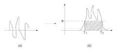
먼저, 도 6의 (a)는 수신부를 통해 수신된 초음파 신호가 변환된 아날로그 신호를 도시한 도이다. 또한, 도 6의 (b)와 같이, 수신된 신호는 증폭기를 통과하며 증폭된 후, 대역 통과 필터(band pass filter)를 거쳐 필터링 된다.First, FIG. 6A illustrates an analog signal obtained by converting an ultrasound signal received through a receiver. In addition, as shown in FIG. 6B, the received signal is amplified while passing through an amplifier and then filtered through a band pass filter.
여기서, 제어수단은 발신부를 통해 송출된 신호가 수신부를 통해 수신되기까지의 시간, 보다 정확하게는 수신부를 통해 수신된 신호가 필터링된 후, 필터링된 신호 레벨과 기준치(α)를 비교하여, 필터링 된 신호가 기준치(α)를 초과하는 순간(T1)까지 걸린 시간(Time Of Flight, 이하 'TOF'라 칭함)을 산출한다. 또한, 제어수단은 산출된 TOF 값에 기초하여 장애물에 대한 거리 및 방향을 감지한다. 'TOF' 값을 이용하여 장애물을 감지하는 실시예는 도 7 및 도 8을 참조한다.Here, the control means is a time until the signal transmitted through the transmitter is received through the receiver, more precisely after the signal received through the receiver is filtered, and compared the filtered signal level and the reference value (α), the filtered A time of flight (hereinafter referred to as "TOF") until the signal T1 exceeds the reference value α is calculated. In addition, the control means detects the distance and direction to the obstacle based on the calculated TOF value. An embodiment of detecting an obstacle using a 'TOF' value will be described with reference to FIGS. 7 and 8.
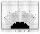
도 7은 도 3에 도시된 초음파 센서에 대한 실시예가 도시된 도로서, 도 6의 (a)는 원통형 장애물 '가'에 대해 감지된 신호로부터 산출된 TOF 값을 도시한 도이고, (b)는 다각형 장애물 '나'에 대해 감지된 신호로부터 산출된 TOF 값을 도시한 도이다. 도 8은 도 7의 (a)를 좀 더 상세히 설명하게 위해 참조되는 도면이다.FIG. 7 is a diagram illustrating an embodiment of the ultrasonic sensor illustrated in FIG. 3. FIG. 6A illustrates a TOF value calculated from a signal detected for a cylindrical obstacle 'ga', and (b). Is a diagram showing the TOF value calculated from the detected signal for the polygon obstacle 'I'. FIG. 8 is a diagram referred to for explaining FIG. 7A in more detail.
도 8을 참조하면, 먼저 가운데 하단의 검은색은 이동 로봇(100)의 형태를 도시한 것이고, 그래프에 도시된 수치는 각 영역(A 내지 E)에서의 TOF 값을 나타낸다. 이때, 이동 로봇(100)의 중앙부인 'C 영역'의 끝단에는 수신부(125)의 제1 센서(125a)가, 'A 영역'의 끝단에는 수신부(125)의 제2 센서(125b)가, 그리고 'E 영역'의 끝단에는 수신부(125)의 제3 센서(125c)가 구비된다. 또한, 'B 영역'의 끝단과 'D 영역'의 끝단에는 발신부(121)의 센서(121a, 121b)가 각각 구비된다.Referring to FIG. 8, first, the black bottom center shows the shape of the
이때, 'B 영역'과 'D 영역'의 끝단에 구비된 발신부(121)의 센서(121a, 121b)로부터 동시에 초음파가 발진되면, 발진된 신호는 장애물에 반사되어 제1 센서(125a), 제2 센서(125b) 및 제3 센서(125c)를 통해 수신된다. 제어수단은 수신부(125)를 통해 수신된 신호에 대한 TOF 값을 산출하고, 산출된 값에 따라 'A 영역' 내지 'E 영역'을 구분하게 된다.At this time, when ultrasonic waves are simultaneously oscillated from the
제어수단은 'A 영역', 'C 영역' 및 'E 영역'의 위치로부터 수신된 신호에 대해 제1 센서(125a), 제2 센서(125b) 및 제3 센서(125c)의 수신 각도를 설정한다. 또한, 제어수단은 'A 영역' 내지 'E 영역'의 TOF 값에 기초하여, 제1 센서(125a), 제2 센서(125b) 및 제3 센서(125c)로부터 장애물의 거리값을 각각 산출한다. 한편, 제어수단은 발신부(121)의 센서(121a, 121b)가 구비된 'B 영역' 및 'D 영역'의 TOF 값을 이용하여, 이동 로봇(100)으로부터 장애물이 위치한 방향을 감지하게 된다. 이때, 제어수단은 감지된 장애물에 대해 산출된 TOF 값으로부터 장애물의 형태도 감지할 수 있게 된다.The control means sets the reception angles of the
또한, 도 7의 (b)의 경우도, 상기와 같이 장애물 '나'에 대해 산출된 TOF 값으로부터 거리 및 방향을 산출하는 것이 가능하며, 감지된 신호의 영역으로부터 장애물 '나'의 형태로 감지할 수 있게 된다.In addition, in the case of FIG. 7B, it is possible to calculate a distance and a direction from the TOF value calculated for the obstacle 'I' as described above, and detect the shape of the obstacle 'I' from the detected signal region. You can do it.
여기서 본 실시예에서는 초음파 센서를 예로 들어 설명하였으나, 상기 센서유닛은 초음파 센서에 국한되지 않고, 신호를 발생시켜 반사된 신호를 수신하는 모든 센서를 포함한다.In this embodiment, the ultrasonic sensor has been described as an example, but the sensor unit is not limited to the ultrasonic sensor, and includes all sensors that generate signals and receive reflected signals.
이하, 상기와 같이 구성되는 이동 로봇의 동작을 좀 더 상세히 설명한다.Hereinafter, the operation of the mobile robot configured as described above will be described in more detail.
먼저, 초음파 센서(120)의 발신부(121)에서는 2개 이상의 센서를 통해 동시에 초음파를 발신하고, 이때 발신된 초음파 신호는 소정 영역으로 방사된다.First, the transmitting
방사된 초음파 신호는 장애물에서 반사되고, 이때 반사된 신호는 수신부(125)의 제1 센서(125a), 제2 센서(125b) 및 제3 센서(125c)를 통해 수신된다.The emitted ultrasonic signal is reflected from an obstacle, and the reflected signal is received through the
한편, 제어수단은 제1 센서(125a), 제2 센서(125b) 및 제3 센서(125c)를 통해 각각 수신된 신호의 수신시간 및 수신된 신호의 레벨 등에 기초하여 TOF 값을 산출한다. 이때, 수신된 신호의 레벨과 기 설정된 기준치(α)를 비교하여, 송출 신호가 수신되어, 수신 신호의 레벨이 기준치(α)를 초과하는 순간(T1)까지 걸린 시간을 산출한다.Meanwhile, the control unit calculates a TOF value based on the reception time of the signal received through the
이때, 제어수단은 산출된 TOF 값에 기초하여 장애물과의 거리 및 방향을 감지하고, 감지된 결과값에 따라 이동 로봇(100)의 움직임을 제어한다.At this time, the control means detects the distance and direction to the obstacle based on the calculated TOF value, and controls the movement of the
이상과 같이 본 발명에 의한 이동 로봇 및 그 제어방법은 예시된 도면을 참조로 설명하였으나, 본 명세서에 개시된 실시예와 도면에 의해 한정되지 않고, 본 발명의 기술사상이 보호되는 범위 이내에서 당업자에 의해 응용이 가능하다.As described above, the mobile robot and the control method thereof according to the present invention have been described with reference to the illustrated drawings, but are not limited to the embodiments and drawings disclosed herein, and those skilled in the art within the scope of protection of the technical idea of the present invention. Application is possible.
이상 설명한 바와 같이, 본 발명의 이동 로봇 및 그 제어방법은 다수개의 발신부 및 수신부를 서로 엇갈리도록 배치함으로써, 센서유닛의 발신부 및 수신부의 범위에 방향성을 부여하고, 다수개의 수신부를 통해 수신된 신호를 특정 값에 의해 구분함으로써, 장애물 측정 불가지역을 최소화하여 보다 정확한 장애물 감지가 가능한 이점이 있다.As described above, the mobile robot and its control method of the present invention by placing a plurality of transmitters and receivers to cross each other, giving a direction to the range of the transmitter and the receiver of the sensor unit, and received through a plurality of receivers By dividing the signal by a specific value, there is an advantage that the obstacle can be detected more accurately by minimizing the area where the obstacle cannot be measured.
또한, 수평방향으로 넓은 영역을 감지할 수 있어, 침대나 쇼파 밑과 같이 높이가 낮은 공간으로의 주행이 용이한 이점이 있다.In addition, it is possible to detect a wide area in the horizontal direction, there is an advantage that it is easy to travel to a low height space, such as under the bed or sofa.
Claims (14)
Translated fromKoreanPriority Applications (3)
| Application Number | Priority Date | Filing Date | Title |
|---|---|---|---|
| KR1020070071896AKR100902929B1 (en) | 2007-07-18 | 2007-07-18 | Mobile robot and its control method |
| PCT/KR2008/004164WO2009011542A1 (en) | 2007-07-18 | 2008-07-16 | Mobile robot and controlling method thereof |
| US12/669,208US8489234B2 (en) | 2007-07-18 | 2008-07-16 | Mobile robot and controlling method thereof |
Applications Claiming Priority (1)
| Application Number | Priority Date | Filing Date | Title |
|---|---|---|---|
| KR1020070071896AKR100902929B1 (en) | 2007-07-18 | 2007-07-18 | Mobile robot and its control method |
Publications (2)
| Publication Number | Publication Date |
|---|---|
| KR20090008720A KR20090008720A (en) | 2009-01-22 |
| KR100902929B1true KR100902929B1 (en) | 2009-06-15 |
Family
ID=40488750
Family Applications (1)
| Application Number | Title | Priority Date | Filing Date |
|---|---|---|---|
| KR1020070071896AExpired - Fee RelatedKR100902929B1 (en) | 2007-07-18 | 2007-07-18 | Mobile robot and its control method |
Country Status (1)
| Country | Link |
|---|---|
| KR (1) | KR100902929B1 (en) |
Cited By (1)
| Publication number | Priority date | Publication date | Assignee | Title |
|---|---|---|---|---|
| CN107913035A (en)* | 2017-12-20 | 2018-04-17 | 深圳市沃特沃德股份有限公司 | Clean the method and its cleaning device at wall edge |
Families Citing this family (3)
| Publication number | Priority date | Publication date | Assignee | Title |
|---|---|---|---|---|
| GB2494442B (en)* | 2011-09-09 | 2013-12-25 | Dyson Technology Ltd | Autonomous vacuum cleaner |
| US11150666B2 (en)* | 2016-08-25 | 2021-10-19 | Lg Electronics Inc. | Mobile robot and control method for controlling the same |
| CN113440049B (en)* | 2020-03-25 | 2023-06-09 | 尚科宁家(中国)科技有限公司 | Cleaning robot and control method thereof |
Citations (5)
| Publication number | Priority date | Publication date | Assignee | Title |
|---|---|---|---|---|
| JP2002131426A (en)* | 2000-10-26 | 2002-05-09 | System Technical Co Ltd | Ultrasonic sensor device |
| KR20040057111A (en) | 2002-12-24 | 2004-07-02 | 엘지전자 주식회사 | Supersnic senser handling method of moving robot |
| US6774596B1 (en)* | 1999-05-28 | 2004-08-10 | Dyson Limited | Indicator for a robotic machine |
| KR20060037008A (en) | 2004-10-27 | 2006-05-03 | 삼성광주전자 주식회사 | Robot vacuum cleaner system and external charging device return method |
| KR20070067807A (en)* | 2005-12-23 | 2007-06-29 | 재단법인 포항산업과학연구원 | Ultrasonic Sensor with Asymmetric Direction |
- 2007
- 2007-07-18KRKR1020070071896Apatent/KR100902929B1/ennot_activeExpired - Fee Related
Patent Citations (5)
| Publication number | Priority date | Publication date | Assignee | Title |
|---|---|---|---|---|
| US6774596B1 (en)* | 1999-05-28 | 2004-08-10 | Dyson Limited | Indicator for a robotic machine |
| JP2002131426A (en)* | 2000-10-26 | 2002-05-09 | System Technical Co Ltd | Ultrasonic sensor device |
| KR20040057111A (en) | 2002-12-24 | 2004-07-02 | 엘지전자 주식회사 | Supersnic senser handling method of moving robot |
| KR20060037008A (en) | 2004-10-27 | 2006-05-03 | 삼성광주전자 주식회사 | Robot vacuum cleaner system and external charging device return method |
| KR20070067807A (en)* | 2005-12-23 | 2007-06-29 | 재단법인 포항산업과학연구원 | Ultrasonic Sensor with Asymmetric Direction |
Cited By (1)
| Publication number | Priority date | Publication date | Assignee | Title |
|---|---|---|---|---|
| CN107913035A (en)* | 2017-12-20 | 2018-04-17 | 深圳市沃特沃德股份有限公司 | Clean the method and its cleaning device at wall edge |
Also Published As
| Publication number | Publication date |
|---|---|
| KR20090008720A (en) | 2009-01-22 |
Similar Documents
| Publication | Publication Date | Title |
|---|---|---|
| US8616061B2 (en) | Ultrasonic sensor | |
| JP6026948B2 (en) | Obstacle detection device | |
| US5319611A (en) | Method of determining range data in a time-of-flight ranging system | |
| US20050137748A1 (en) | Apparatus and method for detecting position of mobile robot | |
| KR100902929B1 (en) | Mobile robot and its control method | |
| US5263006A (en) | Device and process for detecting the presence of a vehicle by means of an ultrasonic device | |
| WO2009011542A1 (en) | Mobile robot and controlling method thereof | |
| WO2015118804A1 (en) | Object detection device | |
| WO2011129001A1 (en) | Obstacle detection system | |
| JP2005043337A (en) | Method for detecting position of mobile robot and apparatus thereof | |
| JP2015200563A (en) | Object detection apparatus | |
| KR101442110B1 (en) | Robot system and operating method thereof | |
| KR101680998B1 (en) | Ultrasonic flow meter, flow velocity measurement method, and flow velocity measurement program | |
| JP2008292168A (en) | Obstacle proximity determination device and obstacle proximity determination method | |
| KR20190093637A (en) | Method for operating the ultrasonic sensor | |
| KR100845528B1 (en) | Connection device and method for obstacle avoidance and automatic charging of mobile robot using anisotropic ultrasonic sensor | |
| JP2000214927A (en) | Autonomous mobile robot and distance measuring device | |
| CN1678133B (en) | Transmitter and acoustic sensor | |
| CN109719736B (en) | Self-moving robot and control method thereof | |
| JP2008097089A (en) | Autonomous traveling device, program thereof and recording medium | |
| KR100757102B1 (en) | Method and device for measuring distance in robot cleaner | |
| JP3851994B2 (en) | Ultrasonic paper number measuring device | |
| JP6162451B2 (en) | Ultrasonic sensor | |
| JPH0926318A (en) | Distance measuring apparatus | |
| KR20040057112A (en) | Supersnic interference prevention structure for robot cleaner |
Legal Events
| Date | Code | Title | Description |
|---|---|---|---|
| A201 | Request for examination | ||
| PA0109 | Patent application | St.27 status event code:A-0-1-A10-A12-nap-PA0109 | |
| PA0201 | Request for examination | St.27 status event code:A-1-2-D10-D11-exm-PA0201 | |
| E902 | Notification of reason for refusal | ||
| PE0902 | Notice of grounds for rejection | St.27 status event code:A-1-2-D10-D21-exm-PE0902 | |
| PN2301 | Change of applicant | St.27 status event code:A-3-3-R10-R13-asn-PN2301 St.27 status event code:A-3-3-R10-R11-asn-PN2301 | |
| T11-X000 | Administrative time limit extension requested | St.27 status event code:U-3-3-T10-T11-oth-X000 | |
| E13-X000 | Pre-grant limitation requested | St.27 status event code:A-2-3-E10-E13-lim-X000 | |
| P11-X000 | Amendment of application requested | St.27 status event code:A-2-2-P10-P11-nap-X000 | |
| P13-X000 | Application amended | St.27 status event code:A-2-2-P10-P13-nap-X000 | |
| E90F | Notification of reason for final refusal | ||
| PE0902 | Notice of grounds for rejection | St.27 status event code:A-1-2-D10-D21-exm-PE0902 | |
| PG1501 | Laying open of application | St.27 status event code:A-1-1-Q10-Q12-nap-PG1501 | |
| P11-X000 | Amendment of application requested | St.27 status event code:A-2-2-P10-P11-nap-X000 | |
| P13-X000 | Application amended | St.27 status event code:A-2-2-P10-P13-nap-X000 | |
| E701 | Decision to grant or registration of patent right | ||
| PE0701 | Decision of registration | St.27 status event code:A-1-2-D10-D22-exm-PE0701 | |
| R18-X000 | Changes to party contact information recorded | St.27 status event code:A-3-3-R10-R18-oth-X000 | |
| GRNT | Written decision to grant | ||
| PR0701 | Registration of establishment | St.27 status event code:A-2-4-F10-F11-exm-PR0701 | |
| PR1002 | Payment of registration fee | St.27 status event code:A-2-2-U10-U11-oth-PR1002 Fee payment year number:1 | |
| PG1601 | Publication of registration | St.27 status event code:A-4-4-Q10-Q13-nap-PG1601 | |
| R18-X000 | Changes to party contact information recorded | St.27 status event code:A-5-5-R10-R18-oth-X000 | |
| PR1001 | Payment of annual fee | St.27 status event code:A-4-4-U10-U11-oth-PR1001 Fee payment year number:4 | |
| FPAY | Annual fee payment | Payment date:20130514 Year of fee payment:5 | |
| PR1001 | Payment of annual fee | St.27 status event code:A-4-4-U10-U11-oth-PR1001 Fee payment year number:5 | |
| FPAY | Annual fee payment | Payment date:20140523 Year of fee payment:6 | |
| PR1001 | Payment of annual fee | St.27 status event code:A-4-4-U10-U11-oth-PR1001 Fee payment year number:6 | |
| FPAY | Annual fee payment | Payment date:20150522 Year of fee payment:7 | |
| PN2301 | Change of applicant | St.27 status event code:A-5-5-R10-R13-asn-PN2301 St.27 status event code:A-5-5-R10-R11-asn-PN2301 | |
| PR1001 | Payment of annual fee | St.27 status event code:A-4-4-U10-U11-oth-PR1001 Fee payment year number:7 | |
| FPAY | Annual fee payment | Payment date:20160524 Year of fee payment:8 | |
| PR1001 | Payment of annual fee | St.27 status event code:A-4-4-U10-U11-oth-PR1001 Fee payment year number:8 | |
| P22-X000 | Classification modified | St.27 status event code:A-4-4-P10-P22-nap-X000 | |
| FPAY | Annual fee payment | Payment date:20170512 Year of fee payment:9 | |
| PR1001 | Payment of annual fee | St.27 status event code:A-4-4-U10-U11-oth-PR1001 Fee payment year number:9 | |
| FPAY | Annual fee payment | Payment date:20180514 Year of fee payment:10 | |
| PR1001 | Payment of annual fee | St.27 status event code:A-4-4-U10-U11-oth-PR1001 Fee payment year number:10 | |
| FPAY | Annual fee payment | Payment date:20190514 Year of fee payment:11 | |
| PR1001 | Payment of annual fee | St.27 status event code:A-4-4-U10-U11-oth-PR1001 Fee payment year number:11 | |
| PR1001 | Payment of annual fee | St.27 status event code:A-4-4-U10-U11-oth-PR1001 Fee payment year number:12 | |
| PN2301 | Change of applicant | St.27 status event code:A-5-5-R10-R13-asn-PN2301 St.27 status event code:A-5-5-R10-R11-asn-PN2301 | |
| PC1903 | Unpaid annual fee | St.27 status event code:A-4-4-U10-U13-oth-PC1903 Not in force date:20210609 Payment event data comment text:Termination Category : DEFAULT_OF_REGISTRATION_FEE | |
| PC1903 | Unpaid annual fee | St.27 status event code:N-4-6-H10-H13-oth-PC1903 Ip right cessation event data comment text:Termination Category : DEFAULT_OF_REGISTRATION_FEE Not in force date:20210609 | |
| P22-X000 | Classification modified | St.27 status event code:A-4-4-P10-P22-nap-X000 | |
| P22-X000 | Classification modified | St.27 status event code:A-4-4-P10-P22-nap-X000 |