KR100900158B1 - Pneumatic powered autoinjector - Google Patents
Pneumatic powered autoinjectorDownload PDFInfo
- Publication number
- KR100900158B1 KR100900158B1KR1020047006936AKR20047006936AKR100900158B1KR 100900158 B1KR100900158 B1KR 100900158B1KR 1020047006936 AKR1020047006936 AKR 1020047006936AKR 20047006936 AKR20047006936 AKR 20047006936AKR 100900158 B1KR100900158 B1KR 100900158B1
- Authority
- KR
- South Korea
- Prior art keywords
- injector
- needle
- force
- driver
- pressurized gas
- Prior art date
- Legal status (The legal status is an assumption and is not a legal conclusion. Google has not performed a legal analysis and makes no representation as to the accuracy of the status listed.)
- Expired - Fee Related
Links
Images


Classifications
- A—HUMAN NECESSITIES
- A61—MEDICAL OR VETERINARY SCIENCE; HYGIENE
- A61M—DEVICES FOR INTRODUCING MEDIA INTO, OR ONTO, THE BODY; DEVICES FOR TRANSDUCING BODY MEDIA OR FOR TAKING MEDIA FROM THE BODY; DEVICES FOR PRODUCING OR ENDING SLEEP OR STUPOR
- A61M5/00—Devices for bringing media into the body in a subcutaneous, intra-vascular or intramuscular way; Accessories therefor, e.g. filling or cleaning devices, arm-rests
- A61M5/178—Syringes
- A61M5/20—Automatic syringes, e.g. with automatically actuated piston rod, with automatic needle injection, filling automatically
- A61M5/2053—Media being expelled from injector by pressurised fluid or vacuum
- A—HUMAN NECESSITIES
- A61—MEDICAL OR VETERINARY SCIENCE; HYGIENE
- A61K—PREPARATIONS FOR MEDICAL, DENTAL OR TOILETRY PURPOSES
- A61K9/00—Medicinal preparations characterised by special physical form
- A61K9/0002—Galenical forms characterised by the drug release technique; Application systems commanded by energy
- A61K9/0004—Osmotic delivery systems; Sustained release driven by osmosis, thermal energy or gas
- A—HUMAN NECESSITIES
- A61—MEDICAL OR VETERINARY SCIENCE; HYGIENE
- A61M—DEVICES FOR INTRODUCING MEDIA INTO, OR ONTO, THE BODY; DEVICES FOR TRANSDUCING BODY MEDIA OR FOR TAKING MEDIA FROM THE BODY; DEVICES FOR PRODUCING OR ENDING SLEEP OR STUPOR
- A61M5/00—Devices for bringing media into the body in a subcutaneous, intra-vascular or intramuscular way; Accessories therefor, e.g. filling or cleaning devices, arm-rests
- A61M5/178—Syringes
- A61M5/31—Details
- A61M5/32—Needles; Details of needles pertaining to their connection with syringe or hub; Accessories for bringing the needle into, or holding the needle on, the body; Devices for protection of needles
- A—HUMAN NECESSITIES
- A61—MEDICAL OR VETERINARY SCIENCE; HYGIENE
- A61M—DEVICES FOR INTRODUCING MEDIA INTO, OR ONTO, THE BODY; DEVICES FOR TRANSDUCING BODY MEDIA OR FOR TAKING MEDIA FROM THE BODY; DEVICES FOR PRODUCING OR ENDING SLEEP OR STUPOR
- A61M5/00—Devices for bringing media into the body in a subcutaneous, intra-vascular or intramuscular way; Accessories therefor, e.g. filling or cleaning devices, arm-rests
- A61M5/48—Devices for bringing media into the body in a subcutaneous, intra-vascular or intramuscular way; Accessories therefor, e.g. filling or cleaning devices, arm-rests having means for varying, regulating, indicating or limiting injection pressure
- A61M5/482—Varying injection pressure, e.g. by varying speed of injection
- F—MECHANICAL ENGINEERING; LIGHTING; HEATING; WEAPONS; BLASTING
- F16—ENGINEERING ELEMENTS AND UNITS; GENERAL MEASURES FOR PRODUCING AND MAINTAINING EFFECTIVE FUNCTIONING OF MACHINES OR INSTALLATIONS; THERMAL INSULATION IN GENERAL
- F16K—VALVES; TAPS; COCKS; ACTUATING-FLOATS; DEVICES FOR VENTING OR AERATING
- F16K17/00—Safety valves; Equalising valves, e.g. pressure relief valves
- F16K17/20—Excess-flow valves
- F16K17/22—Excess-flow valves actuated by the difference of pressure between two places in the flow line
- F16K17/24—Excess-flow valves actuated by the difference of pressure between two places in the flow line acting directly on the cutting-off member
- F16K17/28—Excess-flow valves actuated by the difference of pressure between two places in the flow line acting directly on the cutting-off member operating in one direction only
- F16K17/30—Excess-flow valves actuated by the difference of pressure between two places in the flow line acting directly on the cutting-off member operating in one direction only spring-loaded
- G—PHYSICS
- G05—CONTROLLING; REGULATING
- G05D—SYSTEMS FOR CONTROLLING OR REGULATING NON-ELECTRIC VARIABLES
- G05D7/00—Control of flow
- G05D7/01—Control of flow without auxiliary power
- G05D7/0126—Control of flow without auxiliary power the sensing element being a piston or plunger associated with one or more springs
- G05D7/0133—Control of flow without auxiliary power the sensing element being a piston or plunger associated with one or more springs within the flow-path
- A—HUMAN NECESSITIES
- A61—MEDICAL OR VETERINARY SCIENCE; HYGIENE
- A61M—DEVICES FOR INTRODUCING MEDIA INTO, OR ONTO, THE BODY; DEVICES FOR TRANSDUCING BODY MEDIA OR FOR TAKING MEDIA FROM THE BODY; DEVICES FOR PRODUCING OR ENDING SLEEP OR STUPOR
- A61M5/00—Devices for bringing media into the body in a subcutaneous, intra-vascular or intramuscular way; Accessories therefor, e.g. filling or cleaning devices, arm-rests
- A61M5/178—Syringes
- A61M5/28—Syringe ampoules or carpules, i.e. ampoules or carpules provided with a needle
- A61M5/281—Syringe ampoules or carpules, i.e. ampoules or carpules provided with a needle using emptying means to expel or eject media, e.g. pistons, deformation of the ampoule, or telescoping of the ampoule
- A61M5/282—Syringe ampoules or carpules, i.e. ampoules or carpules provided with a needle using emptying means to expel or eject media, e.g. pistons, deformation of the ampoule, or telescoping of the ampoule by compression of deformable ampoule or carpule wall
- A—HUMAN NECESSITIES
- A61—MEDICAL OR VETERINARY SCIENCE; HYGIENE
- A61M—DEVICES FOR INTRODUCING MEDIA INTO, OR ONTO, THE BODY; DEVICES FOR TRANSDUCING BODY MEDIA OR FOR TAKING MEDIA FROM THE BODY; DEVICES FOR PRODUCING OR ENDING SLEEP OR STUPOR
- A61M5/00—Devices for bringing media into the body in a subcutaneous, intra-vascular or intramuscular way; Accessories therefor, e.g. filling or cleaning devices, arm-rests
- A61M5/178—Syringes
- A61M5/31—Details
- A61M5/32—Needles; Details of needles pertaining to their connection with syringe or hub; Accessories for bringing the needle into, or holding the needle on, the body; Devices for protection of needles
- A61M5/3205—Apparatus for removing or disposing of used needles or syringes, e.g. containers; Means for protection against accidental injuries from used needles
- A61M5/321—Means for protection against accidental injuries by used needles
- A61M5/3243—Means for protection against accidental injuries by used needles being axially-extensible, e.g. protective sleeves coaxially slidable on the syringe barrel
- A61M5/326—Fully automatic sleeve extension, i.e. in which triggering of the sleeve does not require a deliberate action by the user
- A—HUMAN NECESSITIES
- A61—MEDICAL OR VETERINARY SCIENCE; HYGIENE
- A61M—DEVICES FOR INTRODUCING MEDIA INTO, OR ONTO, THE BODY; DEVICES FOR TRANSDUCING BODY MEDIA OR FOR TAKING MEDIA FROM THE BODY; DEVICES FOR PRODUCING OR ENDING SLEEP OR STUPOR
- A61M5/00—Devices for bringing media into the body in a subcutaneous, intra-vascular or intramuscular way; Accessories therefor, e.g. filling or cleaning devices, arm-rests
- A61M5/46—Devices for bringing media into the body in a subcutaneous, intra-vascular or intramuscular way; Accessories therefor, e.g. filling or cleaning devices, arm-rests having means for controlling depth of insertion
Landscapes
- Health & Medical Sciences (AREA)
- Engineering & Computer Science (AREA)
- Life Sciences & Earth Sciences (AREA)
- Veterinary Medicine (AREA)
- Public Health (AREA)
- General Health & Medical Sciences (AREA)
- Animal Behavior & Ethology (AREA)
- Heart & Thoracic Surgery (AREA)
- Hematology (AREA)
- Biomedical Technology (AREA)
- Anesthesiology (AREA)
- Vascular Medicine (AREA)
- General Engineering & Computer Science (AREA)
- Chemical & Material Sciences (AREA)
- Medicinal Chemistry (AREA)
- Pharmacology & Pharmacy (AREA)
- Epidemiology (AREA)
- Bioinformatics & Cheminformatics (AREA)
- Mechanical Engineering (AREA)
- Physics & Mathematics (AREA)
- General Physics & Mathematics (AREA)
- Automation & Control Theory (AREA)
- Infusion, Injection, And Reservoir Apparatuses (AREA)
Abstract
Translated fromKoreanDescription
Translated fromKorean본 발명은 2001년 11월 9일자로 출원된 미국 일부 연속출원 60/337,753 호로 부터 35 U.S.C. §119 아래의 우선권을 주장하는 출원에 관한 것이다.The present invention discloses 35 U.S.C. §119 concerns an application claiming priority under
본 발명은 인간 또는 동물내로 약제를 분사하기 위한 장치에 관한 것이다. 특히, 본 발명은 동물 및 인간 서브젝트(subject)에 약제를 운반할 수 있는 인젝터(injector)와, 동물 또는 인간에 약제를 운반하기 위한 방법에 관한 것이다.The present invention relates to an apparatus for injecting a medicament into a human or animal. In particular, the present invention relates to an injector capable of delivering a medicament to an animal and human subject, and a method for delivering a medicament to an animal or human.
오토매틱 인젝터(이후에는 "오토인젝터"로 언급함)는 의료 산업 및 수의학 산업에서 잘 공지되어 있으며, 동물 또는 인간에게 약제의 바람직한 도스(dose)의 오토매틱 분사을 할 수 있도록 한다. 오토인젝터는 2개의 운반 메카니즘중의 하나에 따라서 일반적으로 설계되는데: 이중의 하나는 니들을 사용하는 운반 메카니즘(이후에는, "니들드(needled)" 오토인젝터로 언급함)이며, 다른 하나는 니들을 사용하지 않는 운반 메카니즘(이후에는 "니들-리스(needle-less) 오토인젝터로 언급함)이다. 이들의 디자인에 어떠한 문제가 있든지간에, 오토인젝터는 간단한 피하의 서린즈(hypodermic syringe)에 대하여 몇몇 장점을 나타내는 것으로 고려된다. 예를 들면, 오토인젝터는 요구시에 약제의 바람직한 도스를 자동적이며 신뢰성이 있게 운반하도록 설계될 수 있기 때문에, 이들은 빠르고, 편리하며, 정확 한 약제의 운반을 용이하게 한다. 특히, 오토인젝터는 치료 물질을 자신이 스스로 처리해야만 하는 인간에 의하여 사용하기에 매우 적합하게 되어 있다. 또한, 오토인젝터가 니들드 분사 메카니즘을 합체하는 곳에서, 상기 니들이 운반 사이클이전, 그 동안 및, 그 이후에 숨겨져서, 서브젝트의 조직내로 가시성의 니들을 관통하는 작용과 관련되는 어떠한 불안도 제거하거나 또는 제거할 수 있도록 설계될 수 있다. 다양한 서로 다른 인섹션 장치는 미국 특허 3,797,489 호와, 제 5,176,645 호와, 제 5,527,287 호, 제 5,300,303 호 및, 제 6,270,479 호와, 미국 특허출원 제 20010005781 호 및, 국제 출원 공개번호 제 WO 94/13342 호 및 제 WO 95/31235 호에 기재되어 있다.Automatic injectors (hereinafter referred to as "auto injectors") are well known in the medical and veterinary industries and enable the automatic injection of the desired dose of medicament to animals or humans. Autoinjectors are generally designed according to one of two transport mechanisms, one of which is a transport mechanism using a needle (hereinafter referred to as a "needled" autoinjector) and the other a needle. It is a transport mechanism that does not use (hereafter referred to as "needle-less autoinjectors). Whatever the problem with their design, the autoinjectors are placed in a simple hypodermic hypodermic syringe. For example, autoinjectors can be designed to automatically and reliably deliver the desired dose of medication on demand, so that they are fast, convenient, and easy to deliver. In particular, autoinjectors are well suited for use by humans who have to deal with therapeutic substances themselves. Where the autoinjector incorporates a needle injection mechanism, the needle is hidden before, during, and after the transport cycle, eliminating any anxiety associated with the action of penetrating the needle of visibility into the tissue of the subject, or Various different insection devices are described in US Pat. Nos. 3,797,489, 5,176,645, 5,527,287, 5,300,303, and 6,270,479, and US Patent Application No. 20010005781. Application Publication Nos. WO 94/13342 and WO 95/31235.
그러나, 이들에 제공하는 장점에도 불구하고, 오토인젝터의 기술 상태는 다양한 약제의 운반을 위하여 일반적으로 설계되지 않는다. 왜냐하면, 니들-리스 오토인젝터에 의하여 운반되는 약제는 분사에 영향을 주기 위해서는 매우 높은 속도(즉, 초당 800피트(feet per second;fps) 내지 1,200 fps)로 통상적으로 가속도기 때문에, 니들-리스 오토인젝터는 어떠한 크기에서 몇 미크론보다 큰 입자를 합체시키는 다양한 약제 또는 약제들의 운반을 위하여 매우 적합하지 않기 때문이다. 또한, 니들드 분사 메카니즘을 포함하는 오토인젝터는 인슐린 또는 에피네프린(epinephrine) 용액과 같은 매우 낮은 속도를 가지는 수용성 용액을 운반하도록 일반적으로 설계되고, 따라서 니들드 분사 메카니즘을 거쳐서 다양한 약제를 운반하기 위하여 찾을 때에 존재하는 성능상의 장애물(performance hurdle)을 통상적으로 나타내지 않는다.However, despite the advantages they provide, the state of the art of autoinjectors is not generally designed for the delivery of various drugs. Because drugs carried by a needle-less autoinjector are typically accelerators at very high speeds (ie 800 feet per second (fps) to 1,200 fps) in order to affect injection, needle-less auto This is because injectors are not well suited for the delivery of various agents or agents that incorporate particles larger than several microns at any size. In addition, autoinjectors with needle injection mechanisms are generally designed to deliver very low water soluble solutions, such as insulin or epinephrine solutions, and are therefore found to deliver a variety of drugs via the needle injection mechanism. The performance hurdle that exists at the time is not typically represented.
적절한 시간의 크기내에서 적절한 게이지의 니들을 통하여 점성 약제를 구동하기 위하여 충분한 크기의 분사 힘을 발생시키는 것은 니들드 분사 장치를 거쳐서 점성 약제를 운반하기 위하여 극복해야만 하는 하나의 성능상의 장애물이다. 서브젝트의 안전과 편안함을 보장하기 위하여, 니들드 분사 장치에 사용되는 니들의 게이지는 통상적으로 약 21 게이지(gauge) 내지 약 31 게이지의 범위이다. 그럼에도 불구하고, 피하의 분사, 근육내의 분사, 또는 관절사이의 분사을 통하여 운반하도록 설계되는 다수의 현존하여 나타나는 약제는, 약 10 포이즈(Poise), 100 포이즈, 1,000포이즈 및 그리고 10,000 포이즈까지의 범위로 있는 점도를 나타낸다. Hagen-Poiseuille Law에 의해서 참고로 쉽게 인식될 수 있는 바와 같이, F=8QμL(R2/r4)이다. 여기에서, "F"는 요구된 분사의 힘을 나타내고, "Q"는 분사되는 물질의 흐름비를 나타내고, "μ"는 분사되는 물질의 점도를 나타내며, "L"은 사용되는 니들의 길이를 나타내고, "R"은 분사되는 물질을 포함하는 용기의 내부 직경을 나타내며, "r"은 사용되는 니들의 내부 직경을 나타내며, 적절한 게이지의 니들을 통한 상기 약제의 분사은 100 파운드에 근접하거나 또는 초과하는 분사 힘을 요구할 수 있다. 예를 들면, 상기 Hagen-Poiseuille Law는 4.5mm의 내부 직경을 가지는 서린즈와, 0.012 인치(24 게이지 니들)의 내부 직경을 가지는 0.5인치 니들을 통하여 10초내에 200 포이즈의 점도를 가지는 0.5 cc의 약제를 운반하기 위하여, 약 100파운드의 분사 힘이 요구된다. 그러나, 현재 사용가능한 니들드 오토인젝터에 제공되는 분사 메카니즘은 상기와 같은 높은 분사 힘을 발생시키기 위하여 일반적으로 설계되지 않는다.Generating an injection force of sufficient magnitude to drive the viscous agent through the needle of the appropriate gauge within the appropriate amount of time is one performance barrier that must be overcome to deliver the viscous agent through the needle injection device. In order to ensure the safety and comfort of the subject, the gauge of the needle used in the needle injection device is typically in the range of about 21 gauge to about 31 gauge. Nevertheless, many existing medicaments that are designed to be delivered through subcutaneous injection, intramuscular injection, or interarticular injection may range from about 10 poises, 100 poises, 1,000 poises, and 10,000 poises. Present viscosity is shown. As can be easily recognized by the Hagen-Poiseuille Law for reference, F = 8QμL (R2 / r4 ). Here, "F" represents the required injection force, "Q" represents the flow ratio of the material to be injected, "μ" represents the viscosity of the material to be injected, and "L" represents the length of the needle used. "R" represents the inner diameter of the container containing the material being sprayed, "r" represents the inner diameter of the needle used, and the injection of the medicament through the needle of the appropriate gauge is close to or exceeds 100 pounds. May require injection force. For example, the Hagen-Poiseuille Law is a drug of 0.5 cc having a viscosity of 200 poises in 10 seconds through a serine with an inner diameter of 4.5 mm and a 0.5 inch needle with an inner diameter of 0.012 inches (24 gauge needle). In order to carry it, an injection force of about 100 pounds is required. However, the injection mechanism provided in the needle autoinjectors currently available is not generally designed to generate such high injection forces.
서브젝트의 불편함은 점성 약제를 운반할 수 있는 니들드 오토인젝터의 설계에 직면하는 두번째 장애물이다. 예를 들면, 적절한 게이지의 니들을 통하여 점성 약제를 운반하는데에 적절한 힘을 갑작스럽게 적용시키는 것은, 특히 이러한 힘의 적용이 현저한 후퇴력 또는 충격력의 전달을 발생시킨다면, 상기 서브젝트를 깜짝 놀라게 한다. 따라서, 점성 약제를 운반할 수 있는 인젝터는 갑작스럽고 잠재적인 고통의 노이즈를 발생시키지 않거나 또는 서브젝트에 중요한 후퇴력 또는 충격력을 전달하지 않고 작동하는 드라이버(driver)를 이상적으로 합체할 수 있다. 또한, 바람직한 게이지의 니들을 통하여 점성 약제를 구동하는데 필요한 동일한 힘을 가지고 상기 서브젝트내로 니들을 구동시키는 것은 불필요한 물리적인 불편함을 상기 서브젝트에 발생시킬 수 있다. 예를 들면, 니들의 게이지가 약 21 내지 31 게이지인 곳에서, 약 1 내지 7 파운드 범위의 삽입력이 가장 안락하게 믿을 수 있다. 상기 니들이 필요한 최소한의 힘으로 삽입될 때에, 몇몇 연구들은 인간의 서브젝트가 최소의 고통을 겪게되는 것을 제안한다. 따라서, 의도되는 서브젝트의 불편함을 최소로 하거나 또는 감소시키기 위하여, 다양한 약제를 분사할 수 있는 인젝터는 조심스럽게 작동해야만 될 뿐만 아니라, 바람직하다면 상기 인젝터는 서브젝트의 불편함을 최소로 하기 위하여 맞추어진 삽입력으로 니들을 삽입할 수 있어야만 한다. 이상적으로는, 이러한 인젝터는 싱글 구동 메카니즘을 사용하는 충분한 시간내에서 바람직한 게이지의 니들을 통하여 점성 약제를 운반하기 충분한 분사 힘과 삽입력을 발생시킨다.Discomfort in the subject is the second obstacle facing the design of a needled autoinjector capable of delivering a viscous agent. For example, the sudden application of an appropriate force to the delivery of a viscous medicament through the needle of an appropriate gauge, particularly if the application of this force results in a significant retraction force or transmission of impact force, amazes the subject. Thus, an injector capable of carrying a viscous medicament can ideally incorporate a driver that operates without generating abrupt and potential pain noise or delivering significant retraction or impact forces to the subject. In addition, driving the needle into the subject with the same force needed to drive the viscous medication through the needle of the desired gauge can cause unnecessary physical inconvenience on the subject. For example, where the gauge of the needle is about 21 to 31 gauge, the insertion force in the range of about 1 to 7 pounds is most comfortable and reliable. When the needle is inserted with the minimum force needed, some studies suggest that the subject of the human being will suffer minimally. Thus, in order to minimize or reduce the discomfort of the intended subject, not only the injectors capable of injecting various medicaments must be operated carefully, but also if desired, the injector is adapted to minimize the discomfort of the subject. The insertion force must be able to insert the needle. Ideally, such injectors generate sufficient injection force and insertion force to deliver the viscous drug through the desired gauge needle within a sufficient time using a single drive mechanism.
본 발명은 인간 또는 동물 서브젝트에 대하여 넓은 범위의 점성을 나타내는 약제를 운반하기 위하여 사용될 수 있는 니들드 인젝터를 제공하는 것이다. 본 발명의 명세서에서, "점도"라는 용어는 Haake Rheometer를 사용하여서 1.0 sec-1 전단율과 25℃에서 측정되는 전단력에 대한 물질의 저항을 언급하는 것이고, "점성"이라는 용어는 Haake Rheometer를 사용하여서 1.0 sec-1의 전단율과 25℃에서 측정되는 1포이즈 이상이 점도를 가지는 약제를 한정하는데에 사용되며, "약제"라는 용어는 인간 또는 동물 서브젝트에 분사에 의하여 처리될 수 있는 어떠한 유리한 작용제도 한정하는데에 사용되는 것이다. 예를 들면, 본 발명의 인젝터를 사용하여서 운반될 수 있는 약제는, 액체, 현탁액, 젤, 용액, 슬러리 및, 어떠한 생리학적이거나 또는 약제학적인 활성제를 포함하는 페이스트(paste), 또는 인간 또는 동물 서브젝트를 위하여 치료하거나 돌보는데에 가치가 있을 수 있는 어떠한 다른 물질을 포함한다.The present invention provides a needle injector that can be used to deliver a medicament that exhibits a wide range of viscosities for human or animal subjects. In the context of the present invention, the term "viscosity" refers to a material's resistance to shear force measured at 1.0 sec-1 shear rate and 25 ° C using a Haake Rheometer, and the term "viscosity" refers to a Haake Rheometer. Whereby a shear rate of 1.0 sec −1 and at least one poise measured at 25 ° C. are used to define a medicament having a viscosity, the term “medicament” being any beneficial action that can be processed by injection into a human or animal subject. It is used to limit institutions. For example, a medicament that can be delivered using the injector of the present invention may be a paste, or human or animal subject, comprising a liquid, suspension, gel, solution, slurry, and any physiological or pharmaceutical active agent. It may contain any other substance that may be of value in treating or caring for.
각각의 실시예에서, 본 발명의 인젝터는 선택된 시간내에 적절한 게이지의 니들을 통하여 점성 약제를 운반하기에 충분한 크기의 분사 힘을 발생시킬 수 있도록 설계될 수 있다. 바람직하기로는, 본 발명의 인젝터는 서브젝트의 불편함을 최소로 하도록 맞추어진 삽입력으로 상기 서브젝트의 조직내로 인젝터의 니들을 구동하도록 설계될 수 있다. 양호하게는, 본 발명의 인젝터의 작동은 간단하고, 조용하며, 현저한 후퇴력 또는 충격력의 전달을 발생시키지 않는다. 또한, 상기 인젝터의 디자인은 매우 가요성이므로, 이것은 상기 인젝터가 약제의 피하, 근육내, 또 는 관절사이의 분사에 요구되는 어떠한 문맥에서도 궁극적으로 사용하도록 한다. 따라서, 본 발명의 인젝터는 넓은 범위의 약제, 즉 점성 약제도 운반하도록 설계될 뿐만 아니라, 본 발명의 인젝터는 조심스럽게 작동되도록 설계됨으로써, 서브젝트에 의하여 겪게되는 어떠한 불안도 최소로 하도록 작용한다.In each embodiment, the injector of the present invention can be designed to generate an injection force of sufficient magnitude to deliver the viscous drug through the needle of the appropriate gauge within a selected time. Preferably, the injector of the present invention can be designed to drive the needle of the injector into the tissue of the subject with an insertion force tailored to minimize the discomfort of the subject. Preferably, the operation of the injector of the present invention is simple, quiet and does not generate significant retraction or impact force transmission. In addition, because the design of the injector is very flexible, this allows the injector to be used ultimately in any context required for subcutaneous, intramuscular, or interarticular injection of the medicament. Thus, the injectors of the present invention are not only designed to carry a wide range of medicaments, ie viscous medicaments, but also the injectors of the present invention are designed to operate carefully, thereby minimizing any anxiety experienced by the subject.
또한, 본 발명은 약제를 분사하는 방법을 포함한다. 각각의 실시예에서, 본 발명의 방법은 바람직한 약제를 제공하는 단계와, 바람직한 게이지의 니들을 제공하는 단계와, 상기 서브젝트의 조직내로 상기 니들을 삽입하는 단계 및, 상기 니들을 통하여 그리고 상기 서브젝트의 조직을 내로 약제를 구동하기에 충분한 분사 힘을 발생시키는 단계를 포함한다. 본 발명의 방법에 제공되는 약제가 어떠한 점도도 나타낼 수 있을지라도, 본 발명의 방법은 점성 약제를 제공하는 단계를 포함하는 것이 양호하다. 본 발명의 방법에 제공되고 사용되는 니들의 게이지와 길이는, 예를 들면 운반되는 약제와, 제안되는 서브젝트와, 상기 분사가 피하, 근육내, 관절사이인지에 의존할 것이다. 또한, 본 발명의 방법에서 발생되는 분사의 힘은 적절한 시간내에서 상기 제공되는 약제의 바람직한 도스를 운반하기에 충분하여야만 한다. 양호하게는, 본 발명의 방법에서 발생되는 분사 힘은 10초내에, 그리고 보다 양호하게는 5초이내에 선택된 약제의 바람직한 도스를 운반하기에 충분하다. 그러나, 본 발명의 방법에서 발생되는 분사 힘의 정확한 크기는 선택된 약제, 선택된 니들의 게이지 길이 및, 바람직한 운반 시간과 같은 다양한 요소에 의존한다. 본 발명의 방법은 분사 힘보다 작은 삽입력을 제공하는 단계를 또한 포함할 수 있다. 상기 삽입력은 니들이 서브젝트의 조직내로 삽입될 때에 서브젝트의 불편함을 최소로 하기 위하여 맞추어질 수 있다. 예를 들면, 의도되는 서브젝트가 인간이고, 제공되는 니들의 게이지가 21 게이지와 31 게이지사이이 범위로 있는 곳에서, 약 1 파운드 및 7 파운드의 삽입력이 양호하고, 약 1 내지 4 파운드의 삽입력은 보다 더 양호하게 된다. 그러나, 본 발명의 방법이 삽입력을 제공하는 단계를 포함하는 곳에서, 상기 삽입력의 크기는 예견되는 서브젝트, 약제를 운반하기 위하여 사용되는 니들의 게이지 및, 상기 분사가 피하, 근육내, 또는 관절사이인지와 같은 몇몇 요소에 따라서 변화될 수 있다.The present invention also includes a method of injecting a medicament. In each embodiment, the method of the present invention provides the steps of providing a preferred medicament, providing a needle of a preferred gauge, inserting the needle into the tissue of the subject, and through and through the needle. Generating sufficient injection force to drive the medicament into the tissue. Although the agent provided in the method of the present invention may exhibit any viscosity, the method of the present invention preferably includes providing a viscous agent. The gauge and length of the needle provided and used in the method of the invention will depend, for example, on the drug being delivered, the proposed subject, and whether the injection is subcutaneous, intramuscular, or between the joints. In addition, the force of the injection generated in the method of the present invention should be sufficient to carry the desired dose of the provided medicament within a suitable time. Preferably, the injection force generated in the method of the present invention is sufficient to deliver the desired dose of the selected medicament within 10 seconds and more preferably within 5 seconds. However, the exact magnitude of the injection force generated in the method of the present invention depends on various factors such as the selected drug, the gauge length of the selected needle, and the desired delivery time. The method of the present invention may also include providing an insertion force less than the injection force. The insertion force can be tailored to minimize discomfort in the subject when the needle is inserted into the subject's tissue. For example, where the intended subject is a human and the gauge of the needle provided is in the range between 21 gauge and 31 gauge, a insertion force of about 1 pound and 7 pounds is good and an insertion force of about 1 to 4 pounds Becomes even better. However, where the method of the present invention comprises providing an insertion force, the magnitude of the insertion force is determined by the subject foreseen, the gauge of the needle used to carry the medicament, and the injection is subcutaneous, intramuscular, or It can change depending on several factors, such as whether the joints are between.
도 1은 멀티스테이지(multistage)의 드라이버를 포함하는 본 발명에 따른 인젝터와, 밸브 메카니즘을 포함하는 액츄에이터를 도시하는 도면.1 shows an injector according to the invention comprising a multistage driver and an actuator comprising a valve mechanism.
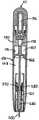
도 2는 밀봉된 마이크로실린더를 도시하는 도면.2 shows a sealed microcylinder.
도 3은 분리된 마이크로실린더를 도시하는 도면.3 shows an isolated microcylinder.
도 4는 싱글스테이지의 드라이버를 포함하는 본 발명에 따른 인젝터와, 관통 메카니즘을 포함하는 액츄에이터를 도시하는 도면.4 shows an injector according to the invention comprising a driver of a single stage and an actuator comprising a through mechanism.
도 5는 멀티스테이지 드라이버를 포함하는 본 발명에 따른 인젝터와, 플런저 메카니즘을 포함하는 액츄에이터를 도시하는 도면.5 shows an injector in accordance with the invention comprising a multistage driver and an actuator comprising a plunger mechanism.
도 6은 멀티스테이지 드라이버를 포함하는 본 발명에 따른 인젝터와, 플런저 메카니즘을 포함하는 액츄에이터를 도시하는 도면.6 shows an injector in accordance with the invention comprising a multi-stage driver and an actuator comprising a plunger mechanism.
도 7 및 도 8은 본 발명의 인젝터에 사용될 수 있고, 플런저 메카니즘을 합체시키는 캡을 도시하는 도면.7 and 8 show caps that can be used in the injector of the present invention and incorporate a plunger mechanism.
도 9는 제한기(restrictor)를 합체시키는 본 발명에 따른 인젝터를 도시하는 도면.9 shows an injector according to the invention incorporating a restrictor.
도 10a은 압력 조절기를 합체시키는 본 발명에 따른 인젝터를 도시하는 도면.10a shows an injector according to the invention incorporating a pressure regulator.
도 10b는 압력 조절기와 제한기를 합체시키는 본 발명에 따른 인젝터를 도시하는 도면.10b shows an injector according to the invention incorporating a pressure regulator and a restrictor.
도 11 내지 도 13은 도 10a 및 도 10b에 도시된 인젝터에 제공되는 압력 조절기를 도시하는 도면.11-13 illustrate a pressure regulator provided on the injector shown in FIGS. 10A and 10B.
도 14 및 도 15는 본 발명의 인젝터를 위한 디스펜셔(dispenser)로서 사용될 수 있는 서린즈 카트리지를 도시하는 도면.14 and 15 show a Serrins cartridge that can be used as a dispenser for the injector of the present invention.
도 16 내지 도 22는 본 발명의 인젝터용 디스펜셔로서 사용될 수 있는 절첩가능한 서린즈 카트리지를 도시하는 도면.16-22 illustrate a collapsible Surinz cartridge that can be used as the dispenser for injectors of the present invention.
도 23은 일체화된 드라이버와, 멀티스테이지 피스톤을 포함하는 디스펜셔를 포함하는 본 발명의 인젝터를 도시하는 도면.FIG. 23 shows an injector of the invention comprising an integrated driver and a dispenser comprising a multistage piston.
도 24는 일체화된 드라이버와, 싱글스테이지 피스톤을 포함하는 디스펜셔를 포함하는 본 발명의 인젝터를 도시하는 도면.FIG. 24 shows an injector of the invention comprising an integrated driver and a dispenser comprising a single stage piston.
도 25는 본 발명의 인젝터에 의하여 발생되는 힘이 드라이버의 공압 실린더내에서 발생되는 압력을 증가시키거나 또는 감소시킴으로써, 또는 상기 드라이버내에 포함되는 피스톤의 표면 영역을 증가시키거나 또는 감소시킴으로써 증가되거나 또는 감소될 수 있는 것을 도시하는 그래프.25 shows that the force generated by the injector of the present invention is increased by increasing or decreasing the pressure generated in the pneumatic cylinder of the driver, or by increasing or decreasing the surface area of the piston included in the driver; Graph showing what can be reduced.
도 26 내지 도 29는 본 발명 방법의 하나의 실시예를 도시하는 도면.26-29 illustrate one embodiment of a method of the present invention.
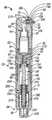
본 발명의 인젝터(10)는 가압된 가스 소스(50)와, 액츄에이터(100)와, 드라이버(150) 및, 디스펜셔(200)를 포함한다. 상기 인젝터(10)의 디스펜셔(200)는 선택된 약제(220)의 바람직한 양을 포함하기 위한 용기(210)와, 상기 선택된 약제(220)의 피하, 근육내 또는 관절사이의 운반을 위하여 적절한 피하주사용 니들과 같은 니들(250)을 포함한다. 상기 액츄에이터(100)는 가압된 가스 소스(50)로 부터 드라이버(150)으로 가압된 가스의 전달을 작동시키고, 가압된 가스가 상기 드라이버(150)으로 운반될 때에, 상기 드라이버(150)는 적어도 삽입력을 발생시킨다. 상기 삽입력은 바람직한 시간내에서 상기 디스펜셔(200)의 니들(250)을 통하여 약제(220)를 추진하기 위한 충분한 크기이다. 양호하게는, 본 발명의 인젝터(10)의 디자인은 매우 가요성이므로, 이것은 상기 인젝터(10)가 약제의 피하, 근육내, 또는 관절사이 분사에 요구되는 어떠한 인간 또는 수의학적인 배경에서 보다 넓은 범위의 약제를 운반하도록 설계되게 한다. 본 발명에 따른 예시적인 인젝터(10)가 도 1에 도시된다.The
가압된 가스의 어떠한 적절한 소스가 본 발명의 인젝터(10)의 가압된 가스 소스(50)로서 사용될 수 있을지라도, 상기 가압된 가스 소스(50)가 가압된 가스의 마이크로실린더(52)를 포함하는 것이 양호하다. 마이크로실린더는 경제적이고, 컴팩트하며, 고압에서 가스의 변화하는 양을 저장할 수 있다. 예를 들면, 상업적으로 이용가능한 마이크로실린더는, 평당 인치당("psi") 약 200파운드 내지 약 3,000 psi 및 그 이상의 범위 압력에서 이산화 탄소, 헬륨, 수소, 산소, 질소 또는 공기와 같은 적절한 가스의 약 1그램 내지 약 3그램으로 신뢰성이 있고 값이 싸게 충전될 수 있다. 또한, 이러한 능력을 가지는 마이크로실린더는 1인치 이하의 길이와, 0.5인치 이하의 직경을 가지는 매우 컴팩트하게 될 수 있다. 따라서, 가압된 가스의 마이크로실린더(52)는 매우 간편한 휴대용이며 사용하기에 쉬운 인젝터의 제조를 허용하는 가압된 가스의 강력하고 경계적인 소스를 제공한다.Although any suitable source of pressurized gas may be used as the
마이크로실린더가 본 발명의 인젝터와 관련하여서 사용되는 곳에서, 2개의 일반적인 마이크로실린더 디자인이 현재 양호하다. 첫번째 일반적인 다지인(54)(이후, "밀봉된 마이크로실린더"로 언급함)은 도 2에 도시되어 있으며, 실린더 몸체(56)와 밀봉부(58)를 가지는 마이크로실린더에 의하여 실현된다. 이러한 마이크로실린더는 South Plainfield, New Jersey의 Leland Limited, Inc.로 부터 상업적으로 이용가능하다. 밀봉된 마이크로실린더내에서 유지되는 가압된 가스를 해제하기 위하여, 상기 밀봉부(58)는 콤프로마이즈(compromise)되어야만 한다(즉, 깨워지거나, 관통되거나, 그렇지 않으면 천공되어야만 한다). 두번째 일반적인 마이크로실린더 디자인(60)(이후에는, "분리 마이크로실린더"로 언급됨)은 도 3에 도시되고, 실린더 몸체(56)로 부터 이격되게 연장되는 긴 넥크(62)를 포함하는 마이크로실린더로 실현되며, 상기 긴 넥크(62)는 소정의 힘을 적용할 때에 분리되도록 설계된다. 이러한 마이크로실린더는 미국 특허 제 6,047,865 호와, 미국 특허 제 5,845,811 호에 기재되어 있으며, BOC Limited of London, U.K.에 의하여 제조된다. 쉽게 인식될 수 있는 바와 같이, 분리 마이크로실린더내에 저장된 가압 가스 는 상기 마이크로실린더의 긴 넥크(62)가 분리될 때에 해제되게 된다. 각 실시예가 본원에서, 밀봉된 마이크로실린더 또는 분리 마이크로실린더를 사용하는 것으로 도시되고 논의될지라도, 본 발명의 인젝터(10)는 어떠한 적절한 디자인의 마이크로실린더(52)를 사용하기 위하여 설계될 수 있다.Where microcylinders are used in connection with the injectors of the present invention, two general microcylinder designs are currently good. The first general designator 54 (hereinafter referred to as "sealed microcylinder") is shown in FIG. 2 and is realized by a microcylinder having a
마이크로실린더(52)가 본원의 인젝터(10)의 가압된 가스 소스(50)로 사용되는 곳에서, 상기 마이크로실린더(52)는 캡(64)내에 배치되는 것이 양호하다. 캡(64)은 마이크로실린더(52)의 크기를 효과적으로 증가시키고, 따라서 상기 마이크로실린더(52)가 인젝터(10)의 몸체(12)에 장착되지 않을 때에 상기 마이크로실린더(52)의 조정을 쉽게 만든다. 제공되는 곳에서, 캡(64)은 바람직한 형상의 마이크로실린더(52)를 수용하도록 형성되며, 어떤 적절한 수단에 의해서 상기 캡(64)내에서 상기 마이크로실린더(52)를 수용하도록 형성된다. 예를 들면, 도 1, 도 4 내지 도 10과, 도 25 및 도 26에 도시된 상기 캡(64)은, 그곳에 배치되는 마이크로실린더(52)가 캡(64)의 내부벽(66)과 상기 마이크로실린더(52)의 경계면에 의하여 발생되는 마찰 결합에 의하여 상기 캡(64)내에서 유지된다. 도 1, 도 4 내지 도 10, 도 25 및 도 26에 도시된 캡(64)이 밀봉된 마이크로실린더 또는 분리 마이크로실린더를 수용하고 유지하도록 설계될지라도, 본 발명에 따른 인젝터(10)에 사용되는 캡(64)은 어떤 적절한 디자인의 마이크로실린더(52)를 수용하고 유지하도록 유지될 수 있다.Where the
또한, 캡(64)은 본원의 인젝터(10)의 몸체(12)에 마이크로실린더(52)의 장착을 용이하게 할 수 있다. 예를 들면, 상기 캡(64)은 인젝터(10)의 몸체(12)에 캡(64)의 고정 부착물을 제공하는 어떠한 본딩 또는 접착 방법을 사용하여서 상기 인젝터(10)의 몸체(12)에 캡(64)의 장착을 허용하도록 형성될 수있다. 또한, 상기 캡(64)은 인젝터(10)의 몸체(12)상에 제공되는 체결 메카니즘의 제 2 부분에 보완적으로 되어 있는 체결 메카니즘의 제 1 부분을 포함할 수 있다. 예를 들면, 상기 캡(64)은 인젝터(10)의 몸체(12)에 형성되는 제 2 나사 영역과 순응하도록 되어 있는 제 1 나사 영역을 구비할 수 있다. 또한, 상기 캡(64)은 인젝터(10)의 몸체(12)상에 제공되는 스냅 피트 커넥터(snap fit connector)의 제 2 부분에 보완적으로 되어 있는 스냅-피트 커넥터의 제 1 부분을 포함할 수 있다. 또한, 상기 인젝터(10)에 마이크로실린더(52)의 장착을 용이하게 하도록 상기 인젝터(10)의 캡(64)과 몸체(12)에 합체될 수 있는 체결 메카니즘의 부가적인 예는, 토글(toggle) 조립체 및 수/암(male/female) 커넥터이다. 그러나, 상기 캡(64)은 인젝터(10)의 몸체(12)에 캡(64)를 고착되게 체결할 수 있는 어떠한 체결 메카니즘도 합체할 수 있다.The
본원의 인젝터(10)로 부터 가압된 가스의 불필요한 배출을 최소로하기 위하여, 하나 이상의 밀봉 부재(18)는 상기 캡(64) 또는 마이크로실린더(52)가 인젝터(10)의 몸체(12)와 인터페이스(interface)된다. 이러한 밀봉 부재(18)는 가압된 가스의 배출을 감소시키거나 또는 제거할 수 있는 O-링 또는 어떠한 다른 적절한 밀봉 장치를 포함할 수 있다. 도 1에 도시된 인젝터(10)는 상기 마이크로실린더(52)가 인젝터의 몸체(12)에 장착될 때에, 상기 마이크로실린더(52)의 밀봉부(58)가 조화롭게되기 이전에 상기 인젝터(10)의 몸체(12)와 마이크로실린더(52)사이에 밀봉부가 형성될 수 있도록 위치되는 밀봉 부재(18)를 포함한다. 도 5 및 도 6은 인젝터(10)의 캡(64)과 몸체(12)사이에 위치되는 밀봉 부재(18)를 포함하는 본원의 인젝터(10)를 도시한다. 상기 밀봉 부재(18)는 캡(64)내에 형성된 시트(seat)(70)내에 위치되고, 상기 인젝터(10)로 부터 가압된 가스이 배출을 감소하거나 또는 제거하는 밀봉부를 발생시킨다. 본원의 인젝터를 도시하는 다양한 도면이 상기 마이크로실린더(52), 캡(64) 및 인젝터(10)의 몸체(12)사이에 특히 위치되는 밀봉 부재(18)를 도시할지라도, 밀봉 부재의 위치 선정은 도시된 정확한 위치에 제한되는 것이 아니다.In order to minimize unnecessary discharge of pressurized gas from the
본원의 인젝터(10)의 액츄에이터(100)는, 가압된 가스 소스(50)로 부터 인젝터(10)의 드라이버(150)까지 가압된 가스의 흐름을 작동시킬 수 있는 어떤 적절한 메카니즘도 포함할 수 있다. 예를 들면, 본원의 인젝터(10)가 가압된 가스의 마이크로실린더(52)를 포함하는 곳에서, 상기 액츄에이터(100)는 작동시에 마이크로실린더(52)를 콤프로마이되며(즉, 상기 밀봉부(58)를 관통, 파괴, 천공하거나, 또는 마이크로실린더(52)의 긴 넥크(62)를 분리), 그리고 가압된 가스가 상기 인젝터(10)의 드라이버(150)를 배출하도록 하는 트리거, 관통 메카니즘, 플런저, 또는 다른 힘 전달 메카니즘을 포함할 수 있다. 또한, 상기 인젝터(10)의 다자인이 상기 액츄에이터(100)가 가압된 가스된 가스 소스(50)를 콤프로마이즈하는 것을 요구하지 않는 곳에서, 상기 액츄에이터(100)는 가압된 가스 소스(50)로 부터 드라이버(150)까지 가압된 가스의 흐름을 작동시키기 위한 밸브를 포함할 수 있다. 상기 인젝터(10)의 우발적인 작동, 또는 "파이어링(firing)"를 방지하기 위하여, 상 기 액츄에이터(100)는 정교한 작용이 인젝터(10)의 사용을 위한 준비에서 실행될 때까지 액츄에이터(100)이 트리거링(triggering)을 방지하는 작용을 하는 안전 메카니즘에 의하여 링크되거나 또는 보호될 수 있다.The
도 1은 본 발명에 따른 인젝터(10)를 도시하는데, 상기 인젝터(10)는 사용자가 가압된 가스 소스(50)로 부터 가압된 가스의 흐름을, 제 1 유체 통로(16)를 통하여 인젝터(10)의 드라이버(150)까지 작동시키도록 허용하는 밸브 조립체(102)를 포함하는 액츄에이터(100)를 구비한다. 상기 밸브 조립체(102)는 밸브 시트(104)와, 밸브 몸체(106), 버턴(108) 및, 스프링, 고무 범퍼, 중합체 범프, 또는 어떤 다른 적절한 탄성 부재를 포함할 수 있는 편향 요소(110)를 포함한다. 상기 편향 요소(110)는 상기 밸브 시트(104)내에 위치되고, 일반적으로 폐쇄된 위치에서 밸브 몸체(106)를 유지하기 위하여 상기 밸브 몸체(106)에 대하여 작용한다. 상기 폐쇄된 위치에서, 상기 밸브 몸체(106)는 제 1 유체 경로(16)를 차단하고 상기 드라이버(150)로의 가스 흐름을 방지한다. 그러나, 충분한 압력이 버턴(108)상에 발생될 때에, 상기 밸브 몸체(106)는 개방된 위치내로 상기 편향 부재(110)에 대하여 이동된다(도 1에 도시됨). 상기 밸브 몸체(106)가 개방된 위치에 있을 때에, 상기 밸브 몸체(106)에 형성된 홈(112)은, 상기 제 1 유체 경로(16)로 부터 드라이버(150)으로의 가압된 가스가 흐르도록 허용하는 제 2 유체 경로(114)를 형성한다. 또한, 상기 밸브 몸체(106)는 하나 이상의 O-링과 같은 하나 이상의 밀봉 부재(18)를 포함한다. 상기 밀봉 부재(18)는, 특히 밸브 몸체(106)가 개방된 상태에 위치될 때에, 상기 밸브 조립체(102)로 부터 가압된 가스의 어떠한 배출도 최소로 하기 위하여 작용한다.1 shows an
도 1를 참고로 하여서 알 수 있는 바와 같이, 본 발명에 따른 인젝터(10)가 밸브 조립체(102)를 포함하는 액츄에이터(100)를 구비하는 곳에서, 상기 인젝터(10)는 이것이 인젝터(10)에 장착될 때에 가압된 가스 소스(50)를 콤프로마이즈하도록 설계된 메카니즘을 구비할 수 있다. 도 1에 도시된 상기 메카니즘은, 제 1 유체 경로(16)를 형성하고, 상기 마이크로실린더(52)를 포함하는 캡(64)이 인젝터(10)의 몸체(12)에 나사결합될 때에 마이크로실린더(52)의 밀봉부(58)를 관통하는 중공 관통 핀(14)을 포함한다. 상기 시스템으로 부터 가압된 가스의 바람직하지 못한 배출을 최소로 하기 위하여, O-링과 같은 밀봉 부재(18)는 상기 마이크로실린더(52)와 인젝터(10)의 몸체(12)사이에 위치될 수 있거나(도 1에 도시됨), 또는 캡(64)과 상기 인젝터(10)의 몸체(12)사이에 위치될 수 있다. 상기 마이크로실린더(52)가 상기 인젝터(10)에 고착될 때에, 상기 중공 관통 핀(14)이 마이크로실린더(52)의 밀봉부(58)를 완전하게 브리취(breach)하기 이전에, 상기 밀봉 부재(18)는 마이크로실린더(52)와 상기 인젝터(10)의 몸체(12)사이에 밀봉부를 형성한다. 일단, 상기 마이크로실린더(52)가 인젝터(10)에 고착되고, 상기 마이크로실린더(52)가 콤프로마이즈된다면, 상기 마이크로실린더(52)로 부터 드라이버(150)으로의 가압된 가스의 흐름은 상기 액츄에이터(100)의 밸브 조립체(102)의 작동을 통하여 간단하게 작동된다.As can be seen with reference to FIG. 1, where the
밸브 조립체 대신에, 상기 액츄에이터(100)는 도 4에 도시된 바와 같이 관통 조립체를 간단하게 포함할 수 있다. 가압된 가스 소스(50)와, 도 4에 도시된 인젝 터(10)의 드라이버(150)사이의 가압된 가스 흐름은 마이크로실린더(52)를 포함하는 캡(64)를 인젝터의 몸체(12)에 장착시킴으로써 간단하게 작동된다. 상기 마이크로실린더(52)를 포함하는 캡(64)이 인젝터(10)에 장착될 때에, 중공의 관통 핀(14)는 상기 마이크로실린더(52)의 밀봉부(58)를 콤프로마이즈하고, 가압된 가스는 상기 마이크로실린더(52)로 부터 상기 제 1 유체 경로(16)를 통하여 드라이버(150)로 운반된다.Instead of the valve assembly, the
분리 마이크로실린더(52)가 본 발명에 다른 인젝터(10)의 가압된 가스 소스(50)로서 사용되는 곳에서, 상기 인젝터(10)의 엑츄에이터(100)는 도 6에 도시된 바와 같이 플런저 조립체(124)를 포함할 수 있다. 상기 플런저 조립체(124)는 인젝터(도시 않음)의 몸체내로 합체될 수 있거나, 또는 상기 플런저 조립체(124)는 마이크로실린더(52)를 포함하는 캡(64)내로 합체될 수 있다(도 6에 도시됨). 이것이 제공되는 곳에 관계없이, 상기 플런저 조립체(124)는 상기 플런저(128)가 배치되는 것내의 통로(126)를 포함한다. 또한, 상기 플런저 조립체(124)는 하나 이상의 밀봉 부재(18)를 또한 포함할 수 있고, 이러한 밀봉 부재는 플런저(128)와 통로(126)사이에 밀봉부를 형성하고, 인젝터(10)의 사용동안에 상기 플런저 조립체(124)를 통하여 가압된 가스의 바람직하지 못한 배출을 최소로 한다. 상기 플런저(128)는 통로(126)내에서 후방 및 전방으로 이동될 수 있고, 마찰 결합 또는 어떤 다른 적절한 수단을 통하여 간단하게 상기 액츄에이터 플런저 메카니즘(124)의 통로(126)내에 유지될 수 있다. 이것이 상기 인젝터(10)의 몸체(12)에 포함되거나, 마이크로실린더(52)를 포함하는 캡(64)내에 포함되는지에 따라서, 상기 플런저 조립체(124)는 충분한 힘을 가지는 플런저(128)의 홈이 마이크로실린더(52)의 긴 넥크(62)를 분리할 수 있도록 위치된다. 도 6에 도시된 플런저 조립체(124)의 플런저(128)가 캡(64)내에 포함된 마이크로실린더(52)의 종방향 축에 일반적으로 수직으로 되어 있을지라도, 도 7 및 도 8에 도시된 바와 같이 상기 형상은 요구되지 않는다.Where a
도 6에 도시된 인젝터는 인젝터(10)의 우발적인 작동을 최소로 하는 것으로 작용하는 안전 메카니즘(20)을 포함한다. 상기 안전 메카니즘(20)은 제 1 부분(22), 제 2 부분(24) 및, 스프링(26)를 포함한다. 상기 제 1 부분(22)는 형상이 일반적으로 원통형이고, 정지부(32)와 포트(31)에서 종결되는 슬롯(30)를 포함한다. 또한, 상기 안전 메카니즘(20)의 제 2 부분(24)은 형상이 일반적으로 원통형이다. 이것의 말단 단부(34)에서, 상기 제 2 부분(24)은 디스펜셔(200)의 조정가능한 팁(230)의 통로를 허용하기 위한 크기로 되어 있는 립(36)을 포함하지만, 상기 립(36)은 기계적인 정지부로서 작용하고, 이것은 제 2 부분(24)의 말단 단부(34)를 통하여 인젝터(10)의 몸체(12)의 통로를 방지한다. 상기 스프링(26)은 인젝터(10)의 몸체(12)에 형성된 시트(38)내에 위치되고, 상기 스프링(26)이 시트(38)내에 위치된 이후에, 상기 안전 메카니즘(20)의 제 1 및 제 2 부분(22,24)은 어떤 적절한 수단에 의하여 함께 고착된다. 예를 들면, 상기 제 1 및 제 2 부분(22,24)은 본딩, 용접, 융접, 나사결합, 스냅-피트로 함께 결합될 수 있다. 상기 스프링(26)은 "안전"위치에서 안전 메카니즘을 편향하기 위하여 상기 제 1 부분(22)의 말단 단부(40)에 대하여 작용한다. 안전 위치에서, 상기 제 1 부분(22)에 포함된 정지부(32)는 인젝터(10)에 포함된 액츄에이터(100)의 작동을 방지한다.The injector shown in FIG. 6 includes a safety mechanism 20 which serves to minimize accidental actuation of the
상기 안전 메카니즘은 스프링(26)에 대하여 상기 제 1 및 제 2 부분(22,24)을 미끄럼 시킴으로써 도 6에 도시된 안전 위치 바깥쪽을 이동됨으로써, 상기 정지부(32)는 액츄에이터(100)와 더 이상 인터페이스되지 않는다. 이러한 점은 서브젝트의 조직에 대하여 일반적으로 수직으로 되게 상기 인젝터(10)를 위치시키고, 안전 메카니즘(20)의 스프링(26)에 의하여 발생되는 편향력을 극복하기에 충분한 하향 힘을 적용시킴으로써 성취될 수 있다. 도 7에 도시된 실시예에서, 상기 제 1 및 제 2 부분(22,24)이 스프링(26)에 대하여 미끌어질 때에 상기 플런저(128)의 넥크(129)는 슬롯(30)을 통과하게 된다. 그러나, 양호하게는, 가압된 가스가 마이크로실린더(52)로 부터 해제될 때에 상기 슬롯(30)은 통로(126)로 부터 배출되는 것으로 부터 상기 플런저(128)의 몸체(130)로 부터 방지하는 크기로 되어 있다.The safety mechanism is moved out of the safety position shown in FIG. 6 by sliding the first and
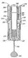
본 발명의 드라이버(150)는 싱글 스테이지 드라이버(152) 또는 멀티 스테이지 드라이버(154)로서 설계될 수 있다. 도 4 및 도 24는 싱글 스테이지 드라이버(152)를 포함하는 본 발명에 따른 인젝터(10)를 도시하는 반면에, 도 1, 도 5, 도 6, 도 9, 도 10 및 도 23은 멀티 스테이지 드라이버(154)를 포함하는 본 발명에 따른 인젝터(10)를 도시한다.The
본 발명의 드라이버(150)가 싱글 스테이지 드라이버(152)에 있는 곳에서, 상기 싱글 스테이지 드라이버(152)는 적어도 하나의 챔버(160)를 구비하는 공압 실린더(158)내에 배치된 싱글 스테이지 피스톤(156)를 포함한다. 상기 싱글 스테이지 드라이버(152)에 제공되는 싱글 스테이지 피스톤(156)은 분사 스테이지(162)를 포함하고, 상기 분사 스테이지(162)와 상기 공압 실린더(158)의 챔버(160)의 벽(164)사이에서 밀봉부를 형성하는 O-링 또는 컵 밀봉부(도 4에는 도시하지 않음)와 같은 밀봉 부재를 포함할 수 있다. 상기 싱글 스테이지 피스톤(156)는 분사 스테이지(162)로 부터 바깥쪽으로 연장되고 그곳으로 이격되는 플런저(166)를 선택적으로 포함하고, 상기 싱글 스테이지 피스톤(156)이 공압 실린더(158)내에서 그 스토로크를 통하여 구동될 때에 상기 디스펜셔(200)에 대하여 작용하도록 위치된다.Where the
가압된 가스가 싱글 스테이지 드라이버(152)의 공압 실린더(158)로 들어갈 때에, 상기 가압된 가스는 분사 스테이지(162)에 대하여 작용하고, 분사 힘으로 그 스트로크를 통하여 상기 싱글 스테이지 피스톤(156)을 구동한다. 상기 싱글 스테이지 피스톤(156)에 의하여 발생되는 분사 힘의 크기는 공압 실린더(158)의 챔버(160)내에 발생되는 압력과 분사 스테이지(162)의 표면 영역을 곱하는 것과 동일하게 된다(힘=압력×면적). 따라서, 소정의 압력 또는 압력 프로파일이 공압 실린더(158)의 챔버(160)내에 발생되는 곳에서, 상기 싱글 스테이지 피스톤(156)에 의하여 발생되는 분사 힘의 크기는, 바람직하기로는 분사 스테이지(162)의 표면 영역을 증가시키거나 또는 감소시킴으로써 조정될 수 있다. 상기 싱글 스테이지 피스톤(154)의 분사 스테이지(162)는 상기 싱글 스테이지 피스톤(156)이 바람직한 시간내에 선택된 약제의 바람직한 도스를 운반하기에 충부한 분사 힘을 발생키는 것을 보장하는 크기로 되어 있다.When the pressurized gas enters the
본 발명에 따른 인젝터(10)에 포함되는 멀티 스테이지 드라이버(154)는, 적어도 2개의 챔버(167,168)를 구비하는 공압 실린더(158)와, 적어도 삽입 스테이지(172)와 분사 스테이지(162)를 가지는 멀티 스테이지 피스톤(170)를 포함한다. 상기 멀티 스테이지 피스톤(170)의 삽입 스테이지(172)는 제 1 표면 영역으로 특징지워지고, O-링과 같은 제 1 밀봉 부재(174)를 포함할 수 있다. 또한, 상기 제 1 밀봉 부재(174)는 제 1 챔버(167)의 벽(178)내에 발생되는 시트(176)에 제공될 수 있다. 상기 멀티 스테이지 피스톤(170)의 분사 스테이지(162)는 삽입 스테이지(172)의 제 1 표면 영역보다 더 크게 되어 있는 제 2 표면 영역에 의하여 특징지워진다. 상기 삽입 스테이지(162)는 멀티스테이지 피스톤(170)이 이것의 스토로크를 통하여 구동될 때에 상기 제 2 챔버(168)의 벽(182)과 상기 분사 스테이지(162)사이에서 밀봉부를 발생시키는 O-링 또는 컵 밀봉부과 같은 제 2 밀봉 부재(180)를 포함할 수 있다. 또한, 상기 멀티 스테이지 피스톤(170)은 분사 스테이지(162)로 부터 바깥쪽으로 연장되고 이것으로 부터 이격되게 연장되는 플런저(166) 일 수 있고, 상기 인젝터(10)의 디스펜셔(200)에 대하여 작용하도록 위치된다. 상기 공압 실린더(158)와 상기 멀티 스테이지 피스톤(170)은, 상기 공압 실린더(158)로 들어가는 가압된 가스가 삽입 스테이지(172)와 분사 스테이지(162)에 대하여 작용하고, 따라서 멀티 스테이지 피스톤(170)를 적어도 삽입력과 분사 힘을 발생시키도록 할 수 있도록 설계된다.The
본 발명의 인젝터에 포함되는 멀티 스테이지 드라이버(154)로 들어가는 가압된 가스는 각 스테이지에 대하여 연속적으로 작용한다. 예를 들면, 도 1, 도 5, 도 6, 도 9, 도 10, 도 23에 도시된 상기 멀티 스테이지 드라이버(154)로 들어가는 가압된 가스는 먼저 삽입 스테이지(172)에 대하여 작용하고, 두번째로 멀티 스테이지 피스톤(170)의 분사 스테이지(162)에 대하여 작용한다. 가압된 가스가 삽입 스테이지(172)에 대하여 작용할 때에, 상기 멀티 스테이지 피스톤(170)은 삽입력을 발생시킨다. 상기 삽입력의 크기는 공압 실린더(158)의 제 1 챔버(167)내에 발생되는 압력과, 상기 삽입 스테이지(172)의 표면 영역을 곱한 것과 동일하다(힘=압력×영역). 따라서, 주어진 압력 또는 압력 프로파일이 제 1 챔버(167)내에 발생되는 곳에서, 상기 멀티 스테이지 피스톤(170)에 발생되는 삽입력은 삽입 스테이지(172)의 표면 영역를 간단하게 증가시키거나 또는 감소시킴으로써 바람직하게 증가되거나 또는 감소될 수 있다. 양호하게는, 멀티 스테이지(170)의 삽입 스테이지(172)는 멀티 스테이지 피스톤(170)이 서브젝트의 불편함을 최소로 하는 삽입력을 발생시킬 수 있는 크기로 될 수 있다.The pressurized gas entering the
일단, 상기 멀티 스테이지 피스톤(170)의 삽입 스테이지(172)가 소정의 스트로크를 통하여 구동된다면, 가압된 가스는 공압 실린더(158)의 제 2 챔버(168)로 들어가며, 상기 삽입 스테이지(162)에 대하여 작용하고, 이것은 상기 멀티 스테이지 피스톤(170)이 분사 힘을 발생시키도록 한다. 상기 멀티 스테이지 피스톤(170)에 의하여 발생되는 분사 힘은 제 2 챔버(168)내에 발생되는 힘과 분사 스테이지(162)의 표면 영역을 곱한 것과 동일하다. 따라서, 주어진 압력 또는 압력 프로파일이 제 2 챔버(168)내에 발생되는 곳에서, 상기 멀티 스테이지 피스톤(170)에 의하여 발생되는 분사 힘의 크기는 상기 분사 스테이지(162)의 표면 영역을 증가시키거나 또는 감소시킴으로써, 바람직하게 증가되거나 감소될 수 있다. 또한, 상기 분사 스테이지(162)는 바람직한 시간내에 선택된 약제의 바람직한 도스를 운반하기에 충분한 분사 힘의 발생을 보장하기 위한 크기로 된다.Once the
본 발명의 인젝터의 드라이버내에서 바람직한 압력 또는 압력 프로파일을 성취하는 것은 하나 이상의 몇몇 디자인 변수를 변경함으로써 성취될 수 있다. 예를 들면, 본 발명의 상기 인젝터가 압력 조절기 또는 제한기를 포함하지 않는다면, 드라이버내에 발생되는 압력은 가압된 가스 소스내에 포함되는 가압 가스의 부피와 압력과, 공압 실린더의 부피 및, 상기 공압 실린더에 포함되는 피스톤의 스토로크에 따른다. 상기 인젝터가 제한기를 포함한다면, 상기 드라이버내에서 발생되는 압력은 가압된 가스 소스내에 포함되는 가압된 가스의 압력 및 부피와, 상기 제한기에 의하여 허용되는 가스 흐름의 최대비 및, 적절한 삽입력이 일단 발생된다면 상기 디스펜셔로 부터 약제가 흐르는 비율에 따른다. 마지막으로, 본 발명의 인젝터가 압력 조절기를 포함하는 곳에서, 상기 드라이버내에서 발생되는 압력은 공압 실린더의 부피와, 피스톤의 스토로크, 또는 상기 디스펜셔로 부터의 약제의 흐름비에 관계없이 제어될 수 있다. 따라서, 바람직한 압력, 일련의 압력, 또는 본원의 인젝터의 드라이버내의 압력 프로파일을 발생시키기 위하여, 몇몇 구성품중의 어떤 하나도 조정되거나 또는 부가될 수 있다.Achieving the desired pressure or pressure profile in the driver of the injector of the present invention can be accomplished by changing one or more of several design variables. For example, if the injector of the present invention does not include a pressure regulator or limiter, the pressure generated in the driver may be dependent upon the volume and pressure of the pressurized gas contained in the pressurized gas source, the volume of the pneumatic cylinder, and the pneumatic cylinder. Follow the stroke of the included piston. If the injector comprises a restrictor, the pressure generated within the driver is such that the pressure and volume of pressurized gas contained in the pressurized gas source, the maximum ratio of gas flow allowed by the restrictor, and the appropriate insertion force If so, it depends on the rate at which the drug flows from the dispenser. Finally, where the injector of the present invention comprises a pressure regulator, the pressure generated in the driver is controlled regardless of the volume of the pneumatic cylinder, the stroke of the piston, or the flow rate of the medicament from the dispenser. Can be. Thus, any one of several components may be adjusted or added to generate a desired pressure, a series of pressures, or a pressure profile in the driver of the injector herein.
도 1, 도 2, 도 5, 도 6, 도 23 및 도 24는 제한기 또는 압력 조절기를 포함하지 않는 본 발명에 따른 인젝터(10)를 도시한다. 상기 인젝터(10)의 드라이버(150)의 공압 실린더(158)내에서 발생되는 압력은, 이상적인 가스 법칙, P1V1=P2V2를 사용하여서 정확하게 예견되고 조정될 수 있다. 상기 가압된 가스 소스(50)의 부피 및 압력이 각각 P1 및 V1로, 상기 공압 실린더(158)의 부피가 V2로 취해진다면, 상기 공압 실린더내에서 발생되는 압력(P2)는 P1 과 V1이 곱을 V2로 나눈것과 동일하다(158). 따라서, 상기 공압 실린더(158)내에 발생되는 압력은 가압된 가스 소스(50)내에 포함되는 가스의 부피 및 압력에 직접 비례하고, 상기 공압 실린더(158)의 부피에는 반비례한다. 이러한 관계를 사용하여서, 상기 제한기와 압력 조절기에서 부족하게 되는 인젝터(10)의 공압 실린더(158)내에 발생되는 압력은 가압된 가스 소스(50)내에 포함되는 가스 압력을 변경하거나, 또는 가압된 가스 소스(50) 또는 공압 실린더(158)의 부피를 간단히 변경함으로써, 바람직한 크기로 조정될 수 있다.1, 2, 5, 6, 23 and 24 show an
쉽게 이해될 수 있는 바와 같이, 본 발명의 인젝터(10)가 제한기 또는 압력 조절기를 포함하지 않는 곳에서, 공압 실린더(158)의 하나 이상의 챔버(160,167,168)에서 발생되는 압력은, 상기 피스톤(156,170)이 이것의 스트로크를 통하여 이동할 때에 적어도 약간 감소하게 될 것이다. 이러한 점은 상기 공압 실린더(158)내에서 발생되는 압력(P2)이 가압된 가스에 의하여 충진되는 부피(V2)에 반비례하기 때문이고, 상기 피스톤(156,170)이 이것의 스트로크를 통하여 이동할 때에, 가압된 가스에 의하여 충진되는 부피(V2)가 증가하기 때문이다. 그러나, 압력(P2)이 공압 실린더(158)의 하나 이상의 챔버(160,167,168)내에 감소되는 정도는 가압된 가스 소스(50)에 포함되는 가스의 압력(P1)과 부피(V1)를 변화시키거나, 또는 상기 피스톤(156,170)이 공압 실린더(158)를 통하여 구동될 때에 부피(V2)에서 변화를 증가시키거나 또는 감소시키는 피스톤(156,170)의 스토로크를 증가시키거나 또는 감소시킴으로써 적어도 부분적으로 제어될 수 있다. 예를 들면, 주어진 부피의 공압 실린더(158)를 위하여, 가압된 가스 소스(50)에 의하여 운반되는 가스의 부피 또는 압력이 증가될 때에, 압력의 떨어짐은 완화된다. 그 반대로, 가압된 가스 소스(50)에 의하여 운반되는 가스의 압력 또는 부피가 감소하게 될 때에, 소정 부피의 공압 실린더내에서의 압력의 떨어짐은 두드러지게 된다. 따라서, 본 발명의 인젝터(10)가 제한기 또는 압력 조절기를 포함하지는 곳에서도, 상기 인젝터(10)의 드라이버(150)에 의하여 발생되는 삽입력 또는 분사 힘의 범위는, 공압 실린더(158)의 부피, 피스톤(156,170)의 각 스테이지(162,172)의 크기 및, 가압된 가스 소스(52)내에 저장되는 가압된 가스의 부피 및 압력을 제어함으로써 제어될 수 있다.As can be readily appreciated, where the
상기 드라이버(150)내에서 발생되는 압력의 제어가 보다 크게 되는 것이 바람직하다면, 본 발명의 제한기(10)는 제한기(300) 또는 압력 조절기(400)를 구비할 수 있다. 도 9는 제한기(300)를 포함하는 본 발명에 따른 인젝터(10)를 도시하는 반면에, 도 10은 압력 조절기(400)를 포함하는 본 발명에 따른 인젝터(10)를 도시한다. 제한기(300) 또는 압력 조절기(400)를 구비하는 본 발명의 인젝터(10)를 제공함으로써, 거의 일정한 가스 압력이 드라이버(150)의 공압 실린더(158)내에서 발 생될 수 있으며, 따라서 거의 일정한 삽입력 또는 분사 힘을 발생시킨다.If it is desired that the control of the pressure generated in the
도 9를 참고로 하여서 이해될 수 있는 바와 같이, 제한기(300)가 본 발명의 인젝터(10)에 포함되는 곳에서, 상기 제한기(300)는 목표된 최대비율로 가스 흐름을 제한하기 위하여 바람직한 크기로 된 오리피스(304)를 가지는 판(302)를 간단하게 포함할 수 있다. 상기 제한기(300)에 의하여 허용되는 흐름비율은 상기 판(302)에 포함되는 오리피스(304)의 크기를 감소시키거나 또는 증가시킴으로써 쉽게 증가되거나 또는 감소된다. 또한, 상기 인젝터(10)는 사용자가 주어진 범위내에서 가스 흐름의 바람직한 비율을 선택하도록 하는 조정가능한 제한기(도시 않음)를 포함할 수 있따. 예를 들면, 조정가능한 제한기는 유체 통로내에서 바람직하게 전진하거나 후퇴되는 스크류 메카니즘을 포함할 수 있다. 상기 스크류 메카니즘이 유체 통로내에서 전진하기 때문에, 상기 유체 통로는 수축되고, 최대 가스 흐름을 매우 작게 허용하게 된다. 그러나, 상기 스크류 메카니즘이 수축하기 때문에, 상기 유체 통로는 팽창되고, 이것은 보다 큰 최대 가스 흐름을 허용한다. 도 9에 도시된 상기 제한기(300)가 상기 액츄에이터(100)와 상기 인젝터(10)의 가압된 가스 소스(50)사이에 위치될지라도, 본 발명의 인젝터(10)에 포함되는 제한기(300)는 상기 액츄에이터(100)와 상기 드라이버(150)의 공압 실린더(158)사이와 같은 다른 적절한 위치에 위치될 수 있다.As can be understood with reference to FIG. 9, where the
상기 제한기(300)에 의하여 허용되는 최대 가스 흐름을 조정함으로써, 본 발명의 인젝터(10)는 거의 일정한 분사 힘을 제공하도록 설계될 수 있다. 제한기(300)의 사용을 통하여 거의 일정한 분사 힘을 성취하기 위하여, 상기 제한 기(300)에 의하여 허용되는 가스 흐름의 최대 흐름비율은 분사 힘이 드라이버(150)의 공압 실린더(158)내에 발생된다면 상기 디스펜셔(200)로 부터 약제가 방출되는 비율에 매치하기 위하여 동조된다(tune). 상기 제한기(300)에 의하여 허용되는 가스 흐름의 최대 비율이 약제(220)가 디스펜셔(200)로 부터 방출되는 비율로 매치하기 위하여 동조된다면, 상기 공압 실린더(158)내의 압력은 약제(220)가 서브젝트로 운반될 때에 거의 일정하게 남아 있게 될 것이다. 따라서, 본 발명의 인젝터(10)는 적절하게 동조된 제한기(300)를 가진 인젝터(10)를 간단하게 제공함으로써 거의 일정한 분사 힘을 발생시키도록 설계될 수 있다.By adjusting the maximum gas flow allowed by the
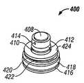
도 10a 내지 도 13은 전형적인 압력 조절기(400)를 도시하며, 상기 조절기는 상기 드라이버(150)에 포함되는 공압 실린더(158)의 부피와, 피스톤(170)의 스토로크, 또는 약제(220)가 디스펜셔(200)로 부터 방출되는 비율에 관계없이 일정한 삽입력 또는 분사 힘이 발생되도록 허용한다. 상기와 같은 도면에 도시된 압력 조절기(400)는 베이스(402)와, 상기 베이스(402)로 부터 외부로 연장되는 원통형 돌출부(404)를 포함한다. 상기 원통형 돌출부(404)는 제 1 밀봉 요소(408)용의 제 1 시트(406)과, 제 2 밀봉 요소(412)용의 제 2 시트(410) 및, 제 1 유체 경로(414)를 포함한다. 상기 제 1 유체 경로(414)는 가압된 가스 소스(50)로 부터 액츄에이터(100)로 가압된 가스의 흐름을 용이하게 한다. 상기 베이스(402)는 제 3 밀봉 요소(418)용의 제 3 시트(416)를 포함하고, 제 1 스프링 요소(420)와, 제 2 스프링 요소(422) 및, 스페이셔 링(424)용의 플렛폼으로 작용한다. 상기 제 1 및 제 2의 스프링 요소(420,422)는 베이스(402)위와, 상기 원통형 돌출부(404)주위에 위치되며, 상기 스페이셔 링(424)는 상기 제 1 및 제 2의 스프링 요소(420,422)위에 위치된다. 상기 압력 조절기에 포함되는 밀봉 요소(408,412,418)는 가스켓 또는 O-링 밀봉부와 같은 어떤 적절한 밀봉 요소를 포함할 수 있다. 어떤 적절한 구조가 본 발명의 인젝터에서 유용하게 압력 조절기(400)를 발생시키기 위하여 사용될 수 있을지라도, 도 10a 내지 도 13에 도시된 압력 조절기(400)는 소정의 레벨에서 또는 그 아래에서 상기 드라이버(150)내에 압력을 유지할 수 있는 컴팩트한 장치를 제공한다.10A-13 illustrate a
사용에서, 가압된 가스는 가압된 가스 소스(50)로 부터 압력 조절기(400)의 제 1 유체 경로(414)를 통하여 상기 드라이버(150)로 통과하게 된다. 이것이 드라이버(150)으로 흘러가서 축적될 때에, 상기 가압된 가스는 압력 조절기(400)의 베이스(402)에 대하여 압력을 발생시킨다. 상기 베이스(402)에 대하여 작용하는 압력은 베이스(402)가 제 1 및 제 2의 스프링 요소(420,422)에 대하여 힘을 발산하도록 하며, 상기 시스템내의 압력이 소정의 임계값에 도달할 때에, 상기 베이스(402)에 의하여 발생되는 힘은 상기 제 1 및 제 2의 스프링 요소(420,422)를 가압하기 시작한다. 이러한 점은 상기 제 1 밀봉부(408)를 개구(426)에 보다 근접되게 가압함으로써, 상기 개구(426)를 통하여 가압된 가스 소스로 부터의 가압된 가스의 흐름을 제한한다. 상기 베이스(420)에 대하여 작용하는 압력이 소정의 임계값에 도달하거나 또는 초과한다면, 상기 베이스(402)에 발생되는 힘은 제 1 및 제 2의 스프링 요소(420,422)를 극복하게 되고, 상기 압력 조절기(402)의 제 1 밀봉부(408)는 개구(426)를 밀봉하며, 이것은 가압된 가스 소스(50)로 부터의 가스 흐름을 종 결시킨다. 상기 압력이 소정의 임계값아래로 감소될 때에, 상기 베이스(402)에 의하여 발생되는 힘은 감소되고, 상기 제 1 및 제 2의 스프링 요소(420,422)는 개구(426)로 부터 상기 제 1 밀봉부(408)를 이격되게 끌어당기며, 이것은 다시 한번더 상기 가압된 가스 소스(50)로 부터 가압된 가스가 흐르도록 허용한다.In use, pressurized gas is passed from the pressurized
도 10a 내지 도 13에 도시된 압력 조절기(400)의 임계 압력은 어떤 바람직한 값으로 쉽게 설정된다. 상기 압력 조절기(400)에 의하여 허용되는 최대 압력은 상기 베이스(402)의 표면 영역과, 상기 제 1 및 제 2의 스프링 요소(420,422)에 의하여 발생되는 결합된 편향력(bias force)에 의하여 결정된다. 예를 들면, 약 100 psi에서 또는 그 아래 내에서 상기 압력을 유지하기 위하여 설계된 압력 조절기는, 약 0.5 인치의 직경을 가지는 베이스(402)와, 2lbs의 결합된 최대 스프링 힘을 발생시키는 제 1 및 제 2의 스프링 요소(420,422)를 제공함으로써 설계될 수 있다. 상기 드라이버(150)내의 압력이 약 100 psi에 도달하거나 또는 초과하게 될 때에, 상기 제 1 및 제 2의 스프링 요소(420,422)에 대하여 베이스(402)에 의하여 발생되는 힘은 20 lbs에 도달하거나 또는 초과하게 되며(힘=압력 x 면적), 이것은 상기 제 1 밀봉부(408)가 개구(426)를 밀봉하도록 하며, 상기 드라이버(150)내로의 가스 흐름을 종결시킨다. 상기 베이스(402)의 표면적 또는 상기 제 1 및 제 2의 스프링 요소(420,422)에 의하여 발생되는 결합된 편향력을 증가시키거나 또는 감소시킴으로써, 압력 조절기(400)는 상기 드라이버(150)내의 어떤 바람직한 최대 압력도 궁극적으로 유지하도록 설계될 수 있다.The threshold pressure of the
도 10b에 도시된 바와 같이, 본 발명의 인젝터(10)는 압력 조절기(400) 또는 제한기(300)만을 포함하는 것으로 제한되지 않는다. 바람직하거나 또는 필요하다면, 본 발명의 인젝터(10)는 압력 조절기(400) 및 제한기(300)를 포함할 수 있다. 또한, 도 10a 및 도 10b를 참고로 하여서 이해할 수 있는 바와 같이, 본 발명의 인젝터(10)가 압력 조절기(10)를 구비하는 곳에서, 상기 압력 조절기(400)는 하우징(430)내에 포함될 수 있다. 이러한 하우징(430)는 인젝터(10)의 몸체(12)내에 수용되도록 설계되며, 상기 하우징(430)는 어떤 적절한 수단을 사용하여서 상기 몸체(12)에 대하여 장착될 수 있다. 예를 들면, 상기 하우징(430)은 인젝터(10)이 몸체(12)에 제공되는 제 2 나사 영역에 대하여 보완적으로 되어 있는 제 1 나사 영역을 포함할 수 있다. 또한, 상기 하우징(430)은 어떤 적절한 접착 방법 또는 본딩 방법을 사용하여서 상기 몸체(12)에 장착될 수 있다. 상기 압력 조절기(400)가 인젝터(10)의 몸체(12)로 분리되는 하우징(430)에 제공될 필요가 없을지라도, 상기 압력 조절기용의 하우징(430)을 제공하는 것은 몸체(12)의 제조를 용이하게 할 수 있으며, 본 발명의 인젝터(10)에서 압력 조절기(400)의 포함을 간략하게 할 수 있다.As shown in FIG. 10B, the
상기 압력 조절기(400)의 하우징(430)의 사용이 본 발명의 인젝터(10)에서 압력 조절기(400)이 포함을 간략하게 하는바, 다수-편(piece)의 몸체(12)로 본 발명의 인젝터(10)를 제공하는 것은 인젝터(10)의 제조를 용이하게 할 수 있다. 예를 들면, 도 5 및 도 6에 도시된 인젝터(10)의 몸체(12)는 근접 부분(40)과 말단 부분(42)으로 구성된다. 상기 근접 부분 및 말단 부분(40,42)은, 예를 들면, 나사체결 메카니즘, 적절한 접착제, 본딩, 또는 용접 방법, 또는 고착의 부착을 제공하 는 어떤 다른 공지된 수단에 의하여 인터페이스(44)에 결합된다. O-링과 같은 밀봉 부재(18)는 인젝터(10)로 부터 가압된 가스의 원치않는 배출을 감소하거나 또는 제거하기 위하여 말단부(40,42)의 인터페이스(44)에 제공될 수 있다. 상기 근접부(40)와 말단부(42)는 인젝터(10)의 조립 및 적절한 작용을 용이하도록 하는 다양한 형상을 가지도록 설계되고, 상기 근접부 및 말단부(40,42)를 서로 다른 편(piece)로 제조함으로써, 각 부분의 다양한 형상의 설계 및 제조는 용이하게 이루어질 수 있다. 예를 들면, 상기 도 5 및 도 6에 도시된 인젝터의 몸체(12)의 근접부 및 말단부(40,42)가 단일편의 몸체로 합체되게 된다면, 상기 제 1 밀봉 부재(174)용의 시트(176)의 제조는 매우 어렵게하고, 이것은 커스텀 툴링(custom tooling)를 요구하고, 본 발명의 인젝터(10)를 제조하는 비용을 유사하게 증가시킨다. 그러나, 도 5 및 도 6에 도시된 인젝터(10)의 근접 부분(40)이 말단부(42)로 부터 분리되게 제조되기 때문에, 상기 제 1 밀봉 부재(174)의 시트(176)는 상기 근접부(40)와 말단부(42)가 인젝터(10)의 몸체(12)를 형성하기 위하여 결합되기 이전에 상기 근접부(40)내에서 쉽고 또한 값이 싸게 제조된다. 따라서, 이것이 요구되지 않을지라도, 본 발명의 인젝터(10)의 몸체(12)는 인젝터(10)의 제조를 용이하도록 하기 위하여 다수의 구성품으로 제조될 수 있다.The use of the
상기 구성품의 진실된 것이 이미 논의된 바와 같이, 본 발명의 인젝터(10)의 디스펜셔(200)의 디자인은 가요성이 있다. 필요로 하는 인젝터(10)의 디스펜셔(200)는 바람직한 약제(220)를 포함하는데에 적절한 서린즈(211)과 같은 저장부(220)과, 서브젝트에 바람직한 약제(220)를 운반하기 위하여 적절하게 게이 지되는 니들(250)과, 상기 저장부(210)로 부터 니들(250)을 통하여 약제를 구동시키기 위한 피스톤(270)를 단지 포함한다. 본원에 도시된 상기 인젝터(10)는 상기 인젝터(10)의 드라이버(150)에 포함되어 있는 싱글 스테이지 또는 멀티 스테이지 피스톤(156,170)로 부터 분리되는 피스톤(270)을 구비하는 디스펜셔(200)를 포함하고, 또한 상기 디스펜셔(200)의 피스톤(270)는 상기 드라이버(150)에 포함되어 있는 피스톤(156,170)의 플런저(166)내로 합체될 수 있다.As the truth of the above components has already been discussed, the design of the
상기 디스펜셔(200)내에 포함되는 니들(250)의 게이지는 실질적인 만큼 작게 선택되는 것이 일반적이다. 상기 니들(250)을 통하여 주어진 약제(220)를 운반하기 위하여 요구되는 힘과 시간이 상기 니들(250)의 직경이 감소될 때에 일반적으로 증가될지라도, 서브젝트의 편한감은 상기 니들(250)의 직경이 감소될 때에 일반적으로 증가하게 된다. 결과적으로, 특히 의도되는 서브젝트가 인간인 곳에서, 상기 디스펜셔에 포함되는 상기 니들(250)의 게이지는 21 게이지로 부터 31 게이지까지의 범위가 양호하다. 보다 양호하게는, 상기 디스펜셔에 포함되는 니들(250)은 24 게이지 및 31 게이지사이의 범위의 게이지가 될 것이며, 보다 양호하게는 상기 니들(250)은 27 게이지 내지 31 게이지의 범위내에 있게 될 것이다. 보다 작은 게이지의 니들이 보다 큰 게이지의 니들에 있는 것이 일반적으로 양호할지라도, 상기 게이지의 차이점은 서브젝트의 편한함을 크게 변경하지 않는 곳에서, 보다 큰 게이지의 니들은 소정의 약제를 운반하기 위하여 요구되는 분사 힘 또는 분사 시간을 감소시키기 위하여 선택될 수 있다. 또한, 21 게이지 내지 31 게이지의 니들이 양호할지라도, 바림직하거나 또는 필요로 하는 곳에서, 본 발명의 인젝터는 양호한 범위 외쪽의 게이지를 가지는 니들을 구비할 수 있다.The gauge of the
가능한 범위로서는, 상기 용기(210)의 내부 직경(DR)은 상기 니들(250)의 게이지에 근접하도록 선택되어야만 한다. 이러한 점은, 상기 니들(250)을 통하여 상기 용기(210)로 부터 점성 약제를 구동하기 위하여 요구되는 분사 힘이, 상기 용기(210)의 내부 직경(DR)이 니들(250)의 내부 직경(DN)으로 부터 이격되게 증가될 때에 지수적으로 증가하게 되기 때문이다. 물론, 상기 니들(250)의 내부 직경(DN)에 대하여 용기(210)의 내부 직경(DR)을 근접시키는 장점은, 디스펜셔(200)의 바람직한 크기 및, 운반될 약제(220)의 부피와 같은 다른 디자인 요소에 대하여 균형을 이룬다.As a possible range, the inner diameter DR of the
또한, 상기 디스펜셔(200)는 편향 메카니즘을 포함할 수 있으므로, 따라서 상기 디스펜셔(200)의 니들(250)과 용기(210)는 삽입력 또는 분사 힘은 드라이버(150)로 부터 상기 디스펜셔(200)에 대하여 소통을 이룰 수 있을 때 까지 수축된 위치에서 유지된다. 상기 인젝터(10)의 드라이버(150)가 싱글 스테이지 피스톤(156)을 포함하는 곳에서, 상기 편향 메카니즘(280)은 삽입력이 상기 디스펜셔의 피스톤(270)에 대하여 발생될 때까지 수축된 위치에서 상기 용기(210)와 니들(250)을 유지시킨다. 그러나, 상기 인젝터(10)의 드라이버(150)이 멀티스테이지 피스톤(170)을 포함하는 곳에서, 상기 편향 메카니즘(280)은 삽입력이 디스펜셔의 피스톤(270)에 대하여 발생될 때 까지 수축된 위치에서 상기 니들(250)과 용기(210)를 유지시킨다. 또한, 상기 인젝터(10)가 멀티스테이지 드라이버(154) 또는 싱글스테이지 드라이버(152)를 포함하는 것에 관계없이, 상기 인젝터(10)내에 발생되는 압력이 분사 사이클이후에 분산되기 때문에, 상기 편향 메카니즘(280)은 용기(210)와, 상기 디스펜셔(200)내의 니들(250)을 자동적으로 수축시킨다.In addition, since the
상기 편향 메카니즘(280)은 수축된 위치에서 상기 용기(210)와 니들(250)를 편향하기 위한 어떤 적절한 장치도 포함할 수 있다. 예를 들면, 상기 편향 메카니즘은 상기 디스펜셔(200)내에서 용기(210)와 니들(250)을 지지하는 코일 스프링(282)을 포함할 수 있다. 또한, 상기 편향 메카니즘(280)은 강성 또는 포움된(foamed) 고무 또는 폴리머 범퍼, 또는 유체 충진된 탄성 블래더(bladder)와 같은 어떤 다른 적절한 편향 부재를 포함할 수 있다. 상기 편향 매커니즘(280)을 가압하기 위하여 요구되는 스프링 비율 또는 힘은 바람직하게는 변화될 수 있으며, 상기 스프링 비율 또는 힘이 용기(210)와 니들(250)을 수축된 위치로 편향하기 위하여 적어도 충분하게 될 수 있도록 제공된다.The
본 발명의 인젝터(10)가 싱글 스테이지 드라이버(152)와 편향 메카니즘을 포함하는 곳에서, 상기 싱글 스테이지 드라이버(152)에 의하여 발생되는 분사 힘과, 편향 메카니즘(280)에 의하여 발생되는 편향력은 바람직한 크기의 효과적인 힘을 제공하기 위하여 조정될 수 있다. 이러한 효과적인 삽입력은 상기 니들이 상기 디스펜셔의 케이싱(219)로 부터 연장되는 힘이며, 본 발명의 인젝터(10)가 싱글 스테이지 드라이버(150)과 편향 메카니즘(280)을 포함하는 곳에서, 상기 효과적인 삽입력은 싱글 스테이지 드라이버(152)에 의하여 발생되는 분사 힘에 편향 메카니즘(280)에 의하여 발생되는 편향력을 뺀 것과 동일하다. 상기 싱글 스테이 지 드라이버(152)에 의하여 발생되는 분사 힘 또는 상기 편향 메카니즘(280)에 의하여 발생되는 편향력을 조정함으로써, 바람직하고 효과적인 삽입력이 성취될 수 있다. 예를 들면, 10 lbs.의 삽입력이 요구되는 곳에서, 약 1 lbs. 내지 약 7 lbs.의 효과적인 삽입력은 약 9 lbs. 내지 약 3 lbs.의 편향력을 발생시키는 편향 메카니즘을 제공함으로써 성취될 수 있다. 보다 높은 삽입력이 필요할지라도, 약 1 lbs. 내지 약 7 lbs.의 효과적인 삽입력이 필요할지라도, 약 1 lbs. 내지 약 7 lbs.의 효과적인 삽입력이 보다 높은 편향력을 발생시킬 수 있는 편향 메카니즘(280)을 제공함으로써 성취될 수 있다. 따라서, 본 발명의 인젝터(10)가 싱글 스테이지 드라이버(152)를 포함하는 곳에서도, 상기 인젝터(10)는 바람직한 시간내에서 선택된 약제를 운반하기에 충분한 분사 힘을 동시에 발생시키면서, 서브젝트의 불편함을 최소로 하기 위하여 맞추어지도록 된 효과적인 삽입력을 제공하도록 설계될 수 있다.Where the
멀티스테이지 드라이버(154)와 편향 메카니즘(280)을 포함하는 인젝터(10)의 효과적인 삽입력은 또한 바람직하게는 조정될 수 있다. 본 발명의 인젝터(10)가 멀티스테이지 드라이버(154)와 편향 메카니즘(280)를 포함하는 곳에서, 상기 효과적인 삽입력은 멀티스테이지 드라이버(154)에 의하여 발생되는 삽입력에 편향 메카니즘(280)에 의하여 발생되는 편향력을 뺀 것과 동일하다. 결과적으로, 멀티스테이지 드라이버(154)와 편향 메카니즘(280)을 포함하는 인젝터(10)에 의하여 제공되는 효과적인 삽입력은 멀티스테이지 드라이버(154)에 의하여 발생되는 삽입력 또는 편향 메카니즘(280)에 의하여 발생되는 편향력을 변경함으로써 쉽게 조정된다. 예 를 들면, 약 1 lbs.의 편향력과 약 1 lbs. 내지 7 lbs.의 효과적인 삽입력을 발생시키는 편향 메카니즘(280)이 바람직한 곳에서, 가압된 가스 소스(50)와, 인젝터(10)의 멀티스테이지 드라이버(154)는 약 2 lbs. 내지 8 lbs.의 삽입력을 발생시키도록 설계될 수 있다. 또한, 약 5 lbs.의 삽입력과, 약 1 lbs. 내지 약 4 lbs.의 효과적인 삽입력을 발생시키도록 설계된 가압된 가스 소스(50)와, 인젝터(10)의 멀티스테이지 드라이버(154()가 바람직할지라도, 상기 인젝터(10)의 디스펜셔(200)는 약 1 lbs. 내지 4 lbs.의 편향력을 발생시키는 편향 메카니즘(280)을 구비할 수 있다. 따라서, 본 발명의 인젝터(10)가 편향 메카니즘(280)과 멀티스테이지 드라이버(154)를 포함하는 곳에서, 상기 인젝터(10)에 의하여 제공되는 효과적인 삽입력은 바람직하기로는, 서브젝트의 불편함을 최소로 하기 위하여 맞추어져 만들어진다.The effective insertion force of the
약 1 lbs. 내지 약 7 lbs.의 범위는 멀티스테이지 및 싱글 스테이지 드라이버(152,154)를 포함하는 본 발명의 인젝터(10)에 대하여 특별하게 논의되는데, 왜냐 하면, 21 게이지 내지 31 게이지 범위의 게이지를 가지는 니들이 사용되는 곳에서, 약 1 lbs. 내지 7 lbs.사이의 효과적인 삽입력은 서브젝트의 불편함을 최소로 할 것으로 고려되기 때문이다. 그러나, 본 발명의 인젝터(10)는 약 1 lbs. 내지 약 7 lbs. 범위의 효과적인 삽입력을 제공하는 이러한 디자인에 제한되는 것은 아니다. 본 발명의 인젝터(10)의 디자인은 매우 가요성이므로, 본 발명의 인젝터(10)는 궁극적으로 어떠한 바람직한 힘을 가진 디스펜셔(200)에 포함되는 니들(250)을 삽입하도록 설계될 수 있다.About 1 lbs. To about 7 lbs. Is specifically discussed for the
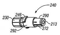
도 14 내지 도 15는 본 발명에 따른 인젝터(10)에서 디스펜셔(200)으로 사용될 수 있는 제 1 서린즈 카트리지(204)를 도시한다(도 1, 도 9 및 도 10 참조). 도 14에 도시되는 바와 같이, 상기 디스펜셔(200)는 슬리브(202) 및 서린즈 카트리지(204)를 포함한다. 상기 슬리브(202)는 인젝터(10)의 몸체(12)에 부착되고, 서린즈 카트리지(204)를 수용하고 부착하기 위하여 설계된다. 어떤 적절한 부착 메카니즘도 상기 인젝터(10)의 몸체(12)에 슬리브(202)를 부착하기 위하여 사용될 수 있다. 예를 들면, 상기 슬리브(202)는 본딩 방법, 용접 방법 또는, 영구적인 부착을 위한 어떤 다른 적절한 수단을 통하여 상기 인젝터(10)의 몸체(12)에 영구적으로 부착될 수 있따. 또한, 상기 슬리브(202)는 예를 들면, 나사체결 메카니즘, 스냅-피트 연결(snap-fit connection), 암/수 연결 메카니즘, 또는 비영구적인 부착부를 제공하는 어떤 다른 적절한 메카니즘을 사용하여서 상기 인젝터(10)의 몸체(12)에 제거가능하게 부착될 수 있다. 상기 슬리브(202)는 서린즈 카트리지(204)의 제거가능한 부착을 용이하게 하며, 상기 서린즈 카트리지(204)가 제거될 때에 상기 공압 실린더(158)를 보호하도록 작용한다.Figures 14-15 show a first
도 14는 슬리브(202), 서린즈 카트리지(204)) 및, 상기 슬리브(202)내에서 상기 서린즈 카트리지(204)의 해제가능한 장착을 용이하게 하는 구성품의 전개 도면이다. 도 14에 도시된 바와 같이, 상기 슬리브(202)는 스페이셔 링(206)과 록킹 링(208)을 포함한다. 일단 상기 슬리브가 인젝터(10)의 몸체(12)에 장착된다면, 상기 록킹 링(208)과 스페이셔 링(206)은 릿지 또는 어떤 다른 적절한 구조체 또는 장치와 같은 부착 부재(212)에 의하여 상기 슬리브(202)내에 유지된다. 상기 서린 즈 카트리지(204)는 서린즈 카트리지(204)의 근접 단부(218)에 포함되는 밀봉부(216)가 인젝터(10)의 몸체(12)에 대향할 때까지 상기 슬리브(202)를 통하여 전진하게 된다. 일단 상기 서린즈 카트리지(204)가 완전히 전진하게 된다면, 이것은 상기 서린즈 카트리지(204)의 케이싱(219)에 포함되어 있는 록킹 부재(223)가 록킹 링(208)에 포함된 편향 록킹 태브(222)를 결합하도록 하는 제 1 토크를 적용시킴으로써 위치내로 록크될 수 있다. 사용된 이후에, 상기 서린즈 카트리지(204)는 서린즈 카트리지(204)의 록킹 부재(223)으로 부터 편향된 록킹 태브(222)를 분리시키는 제 2 토크를 적용시킴으로써 상기 인젝터(10)로 부터 제거될 수 있다. 그러나, 특히 상기 인젝터(10)가 단일 사용용으로 설계되는 곳에서, 슬리브(202)와 서린즈 카트리지(204)를 포함할 필요가 없는 상기 인젝터(10)의 제 1 실시예의 디스펜셔(200)는 상기 인젝터(10)에 영구적으로 부착될 수 있다.FIG. 14 is an exploded view of a
도 15는 서린즈 카티리지(204)의 단면도이다. 도 15를 참고로 하여서 도시된 바와 같이, 상기 서린즈 카트리지(204)의 케이싱(219)은 편향 메카니즘9280)과, 약제(220)가 운반되는 피하조직 니들과 같은 니들(250)과 피스톤(270)을 구비하는 서린즈(211)를 둘러싸게 된다. 상기 편향 메카니즘(280)은 케이싱(219)내에서 상기 서린즈(211)를 지지하고, 상기 용기(210)과 니들(250)을 수축된 위치로 편향시킨다. 상기 편향 메카니즘(280)은 상기 서린즈(211)과 니들(250)이 배치될 수 있는 코일 스프링(282)을 포함하는 것이 양호하다.15 is a cross-sectional view of the Surin's
또한, 도 14 및 도 15에 도시된 서린즈 카트리지(204)는 상기 조정가능한 팁(230)이 케이싱(219)의 말단 단부(221)에 대하여 전진하거나 또는 수축하도록 허 용하는 어떠한 방법에서도 상기 케이싱(219)의 말단 단부(2210를 결합하는 조정가능한 팁(230)을 포함한다. 예를 들면, 상기 조정가능한 팁(230)는 제 1의 나사 영역을 포함할 수 있고, 상기 케이싱(219)의 말단 단부(221)는 상기 케이싱(219)의 말단 단부(221)를 따라서 상기 조정가능한 팁(230)이 전진하거나 또는 수축하도록 허용하는 제 1 나사 영역에 대하여 보완적으로 되어 있는 제 2 나사 영역을 포함할 수 있다. 그러나, 상기 조정가능한 팁(230)은 스냅-피트 메카니즘 또는 래칫 피트 메카니즘과 같은 어떤 다른 적절한 메카니즘이 될 수 있으며, 이것은 상기 조정가능한 팁(230)이 케이싱(219)의 말단 단부(221)를 따라서 전진하거나 또는 수축하도록 허용한다. 상기 서린즈 카트리지(204)가 조정가능한 팁(230)을 포함할 필요가 없을지라도, 이것은 조정가능한 팁(230)을 가진 서린즈 카트리지가 니들이 삽입되는 깊이의 간단한 조정을 용이하도록 한다.In addition, the
도 16 내지 도 22는 본 발명에 따른 인젝터(10)에 사용될 수 있는 절첩가능한(collapsible) 서린즈 카트리지(240)를 도시한다. 상기 절첩가능한 서린즈 카트리지(240)는 절첩가능한 부분(290)을 가지는 케이싱(219)과 고정된 부분(292)을 포함한다. 서린즈(211)는 저장부(210)로서 작용한다. 상기 서린즈(211)는 바람직한 게이지의 니들(250)에서 종결되고, 피스톤(270)을 포함한다. 상기 절첩가능한 서린즈 카트리지(240)는 케이싱(219)내에서 일반적으로 수축된 위치에서 서린즈(211)와 니들(250)을 유지시키는 코일 스프링(282)을 포함하는 편향 메카니즘(28)을 또한 포함한다. 양호하게는, 상기 케이싱(219)의 절첩가능한 부분(290)은 상기 드라이버(150)내에서 보다 짧은 피스톤(156,170)의 사용을 허용하고, 따라서 보다 짧은 인젝터(10)의 구성을 용이하게 한다.16-22 show a
도 5, 도 6 및 도 16 내지 도 22에 도시된 바와 같이, 상기 절첩가능한 서린즈 카트리지(240)의 케이싱(219)은 상기 인젝터(10)의 몸체(12)내에서 상기 절첩가능한 서린즈 카트리지(240)의 장착을 용이하도록 설계된다. 상기 절첩가능한 서린즈 카트리지(240)의 케이싱(219)은 상기 인젝터(10)의 몸체(12)에 제공되는 보완적인 장착 영역(242)내에서 결합되도록 형성되고 크기가 결정된 뿐만 아니라, 상기 케이싱(219)는 상기 절첩가능한 서린즈 카트리지(240)가 본 발명의 인젝터(10)에 장착될 수 있는 적절한 메카니즘을 제공한다. 예를 들면, 도 5, 도 6 및 도 16 내지 도 22에 도시된 바와 같이, 상기 케이싱(219)은 상기 인젝터(10)의 몸체(12)내에 형성되는 제 2 나사 영역에 보완적으로 되어 있는 제 1 나사 영역을 포함할 수 있다. 또한, 상기 절첩가능한 서린즈 카트리지(240)의 케이싱(219)는 인젝터(10)의 몸체(12)내에 형성된 하나 이상의 리세스(도시 않음)에 보완적으로 되어 있는 하나 이상의 록킹 태브(246)(도 20 내지 도 22에 도시됨)를 포함할 수 있다. 도 5, 도 6 및 도 16 내지 도 22가 2개의 특정 장착 메카니즘을 포함하는 절첩가능한 서린즈 카트리지(240)를 도시하고 있을지라도, 본 발명의 인젝터(10)와 사용가능한 절첩가능한 서린즈 카트리지(240)는 어떤 다른 적절한 장착 메카니즘을 합체시킬 수 있다.As shown in FIGS. 5, 6 and 16-22, the
상기 케이싱(219)의 절첩가능한 부분(290)은 이것이 케이싱(219)의 고정된 부분(292)내로와 외부로 위치될 수 있도록 크기가 결정된다. 상기 절첩가능한 부분(290)이 고정된 부분(292)로 부터 완전하게 변위되지 않는 것을 보장하는 것을 돕기 위하여, 상기 절첩가능한 부분(290)의 말단 단부(293)는 제 1 립(lip)(294)을 구비할 수 있으며, 상기 고정된 부분(292)의 근접 단부(295)는 제 2 립(296)을 구비할 수 있다. 상기 절첩가능한 부분(290)이 고정된 부분(292)의 바깥쪽으로 연장될 때에, 상기 제 1 립(294)은 상기 고정된 부분(292)로 부터 상기 절첩가능한 부분(290)을 부가적으로 연장시키는 것을 방지하는 제 2 립(296)을 결합한다. 또한, 상기 절첩가능한 부분(290)은 편향 메카니즘(280)로서 작용하는 코일 스프링(282)을 수용하도록 형성되고 크기가 결정된다. 상기 코일 스프링(282)은 서린즈(211)와 니들(250)의 수축된 위치에 대응되는 일반적으로 연장된 위치에서 상기 절첩가능한 부분(290)을 유지시킨다.The
상기 절첩가능한 부분(290)의 근접 단부(297)는 상기 절첩가능한 서린즈 카트리지(240)내에서 상기 서린즈(212)의 위치선정을 허용하도록 크기가 결정된 오리피스(298)를 포함한다. 그러나, 또한 상기 오리피스(298)는 서린즈(211)가 오리피스(298)를 통하여 위치될 때에 서린즈(211)의 근접 단부(213)를 캐치하도록 크기가 결정된다. 그래서, 분사 힘 또는 삽입력은 서린즈(211)에 포함된 피스톤(270)에 적용되고 상기 서린즈(211)가 코일 스프링(282)에 대하여 변위될 때에, 상기 절첩가능한 부분(290)은 케이싱(219)의 고정된 부분(292)내로 상기 서린즈(211)가 변위하게 된다(도 19에 도시됨). 중요한 것은, 상기 절첩가능한 부분(290)이 케이싱(219)의 고정된 부분(292)내에 변위되기 때문에, 상기 드라이버(150)에 포함된 멀티스테이지 또는 싱글 스테이지 피스톤(156,170)의 플런저(166)는 상기 서린즈(211)로 부터 약제(220)의 바람직한 도스를 배출하기에 충분히 길게만 될 필요가 있다. 이와는 반대로, 서린즈 카트리지가 도 14 및 도 15에 도시된 서린즈 카트리지(204)와 같은 절첩가능한 부분(290)을 포함하지 않는 곳에서, 상기 피스톤(156,170)의 플런저(166)는 상기 서린즈 카트리지(204)내에 서린즈(211)를 변위시키고, 약제(220)의 바람직한 도스를 배출하기에 충분히 길어야만 한다.The
바람직하다면, 상기 절첩가능한 서린즈 카트리지(240)는 상기 절첩가능한 서린즈 카트리지(240)가 인젝터(10)에 장착되기 이전에 상기 서린즈(211)의 우발적인 가압을 최소로 하기 위하여 작용하는 록킹 메카니즘을 구비할 수 있다. 예를 들면, 도 20 내지 도 22에 도시된 바와 같이, 상기 절첩가능한 부분은 절첩가능한 부분(290)의 외부 표면으로부터 이격되게 연장되는 하나 이상의 이어(ear)(27)를 포함할 수 있다. 상기 절첩가능한 부분(290)가 록크된 위치에 있을 때에, 상기 하나 이상의 이어(272)는 케이싱(219)의 고정된 부분(292)의 근접 단부(295)를 통과할 수 없으며, 따라서 상기 절첩가능한 부분(29)이 고정된 부분(292)내에서 변위되는 것을 방지시킨다. 언록크된 위치에서, 상기 하나 이상의 이어(272)는 케이싱(219)의 고정된 부분(292)의 근접 단부(295)에 제공되는 하나 이상의 대응되는 통로(276)와 정렬된다. 상기 하나 이상의 대응되는 통로(276)는 상기 하나 이상의 이어(272)가 케이싱(219)의 고정된 부분(292)의 근접 단부(295)를 통과하도록 허용함으로써, 상기 절첩가능한 부분(290)이 상기 고정된 부분(292)내에 변위되도록 허용한다. 양호하게는, 상기 인젝터(10)의 몸체(12)와, 절첩가능한 서린즈 카트리지(240)는, 상기 인젝터(10)에 대하여 절첩가능한 서린즈 카트리지(240)를 장착시키는 것은 하나 이상의 대응되는 통로(276)와 상기 하나 이상의 이어(272)를 정렬시키면서, 상기 인젝터(10)로 부터 상기 절첩가능한 서린즈 카트리지(240)를 제거하는 것이 하나 이상의 대응되는 통로(276)와 상기 하나 이상의 이어(272)를 오정렬시킨다.If desired, the
바람직하다면, 상기 절첩가능한 서린즈 카트리지(240)는 조정가능한 팁(230)을 포함할 수 있으며, 상기 팁은 조정가능한 팁(230)이 케이싱(219)의 말단 단부(221)에 대하여 전진하거나 또는 수축되도록 허용하는 어떤 방법으로 상기 케이싱(219)의 말단 단부(221)를 결합시킨다. 또한, 상기 조정가능한 팁(230)은 상기 케이싱(219)의 말단 단부(221)에 제공되는 제 2 나사 영역에 보완적인 제 1 나사 영역을 포함할 수 있다. 그러나, 조정가능한 팁(230)은 상기 케이싱(219)의 말단 단부(221)을 따라서 상기 조정가능한 팁(230)을 전진시키거나 또는 후퇴시키도록 허용하는 스냅-피트 메카니즘 또는 래칫 피트 메카니즘과 같은 어떤 다른 적절한 메카니즘에 의하여 장착될 수 있다.If desired, the
또한, 본 발명의 인젝터(10)는 공압 실린더(158)내에 발생되는 가스 압력을 분산하기 위한 압력 릴리프 메카니즘을 포함할 수 있다. 예를 들면, 본 발명의 인젝터(10)는 일단 상기 피스톤(170)이 공압 실린더(158)내의 소정의 위치에 도달하게 된다면 가압된 가스의 벤팅(venting)을 허용하도록 설계될 수 있다. 도 5에 도시된 바와 같이, 상기 드라이버(150)의 공압 실린더(158)는 벤트 챔버(500)에 종결될 수 있다. 상기 벤트 챔버(500)는 상기 피스톤(170)과 공압 실린더(158)사이에 발생되는 밀봉부가 상기 피스톤(170)이 소정의 스트로크의 단부에 도달할 때에 깨어질 수 있도록 크기가 결정된다. 일단 상기 피스톤(170)과 공압 실린더(158)사이 의 밀봉부가 깨어진다면, 상기 공압 실린더(158)로 부터 가압된 가스가 배출되어서 상기 벤트 챔버(500)내로 들어가게 된다. 도 5에 도시된 인젝터는 상기 벤트 챔버(500)내로 이동하는 가압된 가스는 상기 디스펜셔(200)의 케이싱(219)주위에 또는 그것을 통하여 흐름으로써 상기 인젝터(10)를 타출하기에 자유롭게 되도록 설계된다. 그러나, 바람직하다면, 상기 벤트 챔버(500)는 상기 벤트 챔버(500)로 부터 상기 인젝터(10)의 몸체(12)를 통하여 그리고, 상기 몸체(12)의 외부 표면(13)까지 연장되는 유체 경로(도시 않음)을 또한 포함할 수 있다. 이러한 유체 경로는, 가압된 가스의 보다 빠른 벤팅이 바람직한 곳이나, 또는 상기 인젝터(10)의 디자인이 벤트 챔버(500)내로 흐르게 되는 가압된 가스가 상기 디스펜셔(200) 주위 또는 그것을 통하여 탈출하도록 허용하지 않는 곳에 바람직하거나 또는 필요할 수 있다.The
도 6은 본 발명의 인젝터(10)의 액츄에이터(100)로서 작용하는 플런즈 조립체(124)내로 합체될 수 있는 또 다른 압력 릴리프 메카니즘을 도시한다. 이러한 압력 릴리프 메카니즘은 플런저 조립체(124)의 플런저(128)의 몸체(130)내에 형성되는 유체 경로(510)를 포함한다. 상기 유체 경로(510)는 상기 플런저(128)의 측부에 형성되는 벤트(512)를 포함한다. 상기 벤트(512)가 플런저 조립체(124)의 밀봉 부재(18)의 내부쪽에 위치될 때에, 밀봉된 환경은 상기 인젝터(10)내에서 유지된다. 그러나, 상기 플런저(128)는 상기 벤트(512)가 밀봉 부재의 외부쪽에 위치될 수 있도록 변위된다면, 상기 인젝터(10)의 내부 및 외부사이의 유체 소통이 허용된다. 상기 플런저(128)가 가압되고 상기 마이크로실린더(52)가 타협될 때에, 상기 마이크로실린더(52)로 부터 탈출되는 가압된 가스는 유체 통로(510)로 들어가서 상기 플런저(128)에 대하여 작용하며, 이것은 상기 벤트(512)가 밀봉 부재(18)의 외부쪽위에 위치될 수 있도록 상기 플런저(128)를 변위시키기에 충분한 변위력을 발생시킨다. 그러나, 상기 플런저(128)가 가압된 가스로 부터 발생되는 변위력와 동일하거나 또는 더 크게 가압되는한, 상기 플런저(128)는 변위되지 않으며, 상기 인젝터(10)의 내부사이와 상기 외부 환경사이의 유체 소통이 방지될 것이다. 그러나, 상기 플런저(128)가 운반 사이클의 단부에서와 같이 해제된다면, 상기 벤트(512)가 밀봉 요소(18)의 외부쪽에 위치되고 상기 인젝터(10)내에 포함되는 가압된 가스가 플런저(128)를 통하여 상기 인젝터(10)를 나오게 될 수 있도록 변위될 것이다.FIG. 6 illustrates another pressure relief mechanism that may be incorporated into the
상기 인젝터(10)가 안전 메카니즘(20)을 포함하는 곳에서, 상기 안전 메카니즘(20)은 도 6에 도시된 압력 릴리프 메카니즘의 적절한 작용을 보장하는 것을 돕도록 설계될 수 있다. 예를 들면, 도 6에 도시된 바와 같이, 상기 안전 메카니즘(20)의 제 1 부분(22)에 포함된 슬롯(30)의 폭은 플런저(128)의 몸체(130)의 폭보다 더 작게된다. 그래서, 상기 안전 메카니즘(20)이 안전 위치 바깥쪽으로 이동할 때에, 상기 플런저(128)는 상기 플런저(128)에 형성된 벤트(512)가 밀봉 부재(18)의 외부쪽에 위치되는 정도로 변위될 수 없다. 그러나, 상기 안전 메카니즘(20)이 안전 위치내로 뒤로 이동할 때에, 상기 슬롯(30)은 오리피스(512)가 밀봉 부재(18)의 외부쪽에 위치될 수 있도록 플런저(128)의 몸체(130)가 변위되도록 허용하는 크기가 되는 포트(31)내로 개방된다. 또한, 상기 안전 메카니즘(20)의 정지부(32)는 상기 플런저(128)가 플런저 메카니즘(124)의 통로(126)로 부터 완전히 배출되는 것을 방지하는 립(33)을 포함할 수 있다. 따라서, 본 발명의 인젝터(10)는 인젝터(10)를 우연하게 연소하는 가능성을 최소로 할 뿐만 아니라, 가압된 가스가 인젝터(10)로 부터 적절하게 벤트되는 것을 보장하기 위하여 벤팅 메카니즘과 협력하는 작용을 하게 되는 안전 메카니즘(20)을 포함할 수 있다.Where the
특히, 상기 드라이버(150)와 본 발명의 인젝터(10)의 디스펜셔(200)는 분리된 장치가 필요하지 않는다. 도 23 및 도 24에 도시된 바와 같이, 상기 디스펜셔(200)는 인젝터(10)의 구성을 간략하게 위하여 상기 드라이버를 합체시킬 수 있다. 이러한 예에서, 상기 디스펜셔(200)의 서린즈(211)와 같은 저장부(210)는 드라이버의 공압 실린더의 적어도 한 부분으로서 작용하고, 상기 디스펜셔(200)의 피스톤(270)는 저장부(210)내에 포함된 약제(220)에 대하여 직접 작용하는 싱글스테이지 피스톤(156) 또는 멀티스테이지 피스톤(170)으로서 설계될 수 있다. 이것은 인젝터(10)의 크기를 감소시키고, 상기 인젝터(10)를 제조하기 위하여 사용되는 재료의 양을 감소시키기 때문에, 상기 디스펜셔(20)내에 드라이버를 합체시키는 것은 보다 경제적이며 휴대용인 장치를 제공한다. 그러나, 상기 드라이버와 디스펜셔(200)가 일체로 되는 곳에서, 상기 피스톤(156,170)의 단면 직경은 저장부(210)의 최대 내부 직경을 제한한다. 도 23 및 도 24에 도시된 인젝터(10)가 압력 조정기 또는 제한기를 포함하지 않는다면, 상기 일체로 된 드라이버 및 디스펜셔(200)를 포함하는 인젝터(10)가 이미 설명된 바와 같이 압력 조절기 또는 제 한기를 구비할 수 있다.In particular, the
또한, 본 발명의 인젝터는 단일 사용 또는 다중 사용을 위하여 설계될 수 있다. 상기 인젝터가 단일 사용을 위하여 설계되는 곳에서, 상기 인젝터의 각 구성품은 단일 사용이후에 배치되도록 설게되며, 단일 하우징에 영구히 합체될 수 있다. 그러나, 본 발명의 인젝터가 다중 사용의 인젝터로서 설계되는 곳에서, 상기 인젝터의 적어도 하나는 각각의 사용을 위하여 설계된다. 상기 액츄에이터 및 드라이버에 관계없이, 본 발명의 다중 사용 인젝터는 구체적인 장치로서 설계되며, 상기 가압된 가스 소스 및 본 발명에 따른 다중 사용의 인젝터의 디스펜셔가 모듈러(modular) 구성품으로서 설계되는 것이 양호하다. 이러한 디자인은 상기 액츄에이터 또는 인젝터의 드라이버로 부터 그리고 그곳에 상기 가압된 가스 소스와 디스펜셔의 부착 및 분리를 용이하게 하도록 한다.In addition, the injectors of the present invention can be designed for single use or multiple use. Where the injector is designed for single use, each component of the injector is designed to be placed after a single use and can be permanently incorporated in a single housing. However, where the injectors of the invention are designed as multi-use injectors, at least one of the injectors is designed for each use. Regardless of the actuator and driver, the multi-use injector of the present invention is designed as a specific device, and it is preferred that the dispenser of the pressurized gas source and the multi-use injector according to the present invention be designed as a modular component. . This design facilitates the attachment and detachment of the pressurized gas source and dispenser from and to the driver of the actuator or injector.
본 발명의 인젝터는 바람직한데, 왜냐 하면 상기 인젝터의 디자인은 가요성으로 되어 있기 때문이며, 이것은 본 발명의 인젝터가 넓은 범위의 점성을 나타내는 약제를 운반하도록 설계된다. 특히, 본 발명의 인젝터는 다양한 약제의 운반을 위하여 매우 적합하며, 1 포이즈 이상, 10 포이즈 이상, 20 포이즈 이상, 50 포이즈 이상, 또는 100 포이즈 이상의 점도를 가지는 다양한 약제를 운반하기 위하여 설계될 수 있다. 일반적으로, 본 발명의 인젝터는 약 5 lbs. 내지 약 200 lbs.의 범위를 가지는 삽입력을 발생시키기 위하여 형성될 것이다. 그러나, 본 발명의 인젝터의 디자인은 약 5 lbs. 내지 200 lbs.사이의 범위내에 있게 되는 삽입력을 제공하는 인젝터에 제한되지 않는다. 본 발명의 인젝터는 바람직한 시간내에서 선택 된 약제의 바람직한 도스의 운반을 보장하기 위하여 맞추어지는 어떤 바람직한 삽입력도 발생시키기 위하여 형성될 것이다.The injector of the present invention is preferred because the design of the injector is flexible, which is designed so that the injector of the present invention carries a medicament exhibiting a wide range of viscosities. In particular, the injectors of the present invention are well suited for the delivery of a variety of medicaments, and can be designed to deliver a variety of medicaments having a viscosity of at least 1 poise, at least 10 poise, at least 20 poise, at least 50 poise, or at least 100 poise. . Generally, the injector of the present invention is about 5 lbs. And to generate an insertion force in the range from about 200 lbs. However, the design of the injector of the present invention is about 5 lbs. It is not limited to injectors that provide an insertion force that is within the range of between 200 and 200 lbs. The injectors of the present invention will be formed to generate any desired insertion force that is tailored to ensure the delivery of the desired dose of the selected medicament within the desired time.
Hagen-Poiseuille 법칙은 소정의 시간내에서 선택된 약제의 바람직한 도스를 운반하기 위하여 요구되는 삽입력을 결정하는데에 사용될 수 있다. 예를 들면, 4.5 mm의 내부 직경을 가지며, 0.012 인치의 내부직경을 가지는 0.5 인치 니들(24 게이지 니들)을 가지는 서린즈를 거쳐서 10초내에 200포이즈의 점도를 구비한 0.5 cc의 약제를 운반하기 위하여, 상기 Haugen-Poiseuille 법칙은 약 파운드의 분사 힘이 요구된다는 것을 지시한다. 이러한 힘의 결정은 선택된 서린즈 및 니들을 통하여 운반될 어떠한 선택 약제의 어떠한 도스용으로 겪게될 수 있다. 쉽게 이해되는 바와 같이, 상기 약제의 점도가 일정하게 남아 있을 때에도, 상기 Hagen-Poiseuille 법칙로 표현되는 하나 이상의 변수를 조정하는 것은 서로 다르게 요구되는 분사 힘을 발생시킬 것이다. 따라서, 운반될 약제의 유동학적인 성질이 동일하게 남아 있는 곳에서도, 보다 크거나 또는 보다 작은 분사 힘은 예를 들면, 바람직한 운반 시간, 사용될 니들의 길이 및 게이지와, 니들을 통하여 배출하기 이전에 약제를 포함하는데 사용되는 서린즈 또는 다른 저장부의 직경에 의존하게 된다.Hagen-Poiseuille's law can be used to determine the insertion force required to deliver the desired dose of the selected medicament within a given time. For example, to deliver 0.5 cc of medication with a viscosity of 200 poises in 10 seconds via a serine with a 0.5 inch needle (24 gauge needle) having an internal diameter of 4.5 mm and an internal diameter of 0.012 inches. In order to achieve this, the Haugen-Poiseuille law indicates that about a pound of injection force is required. Determination of this force can be experienced for any dose of any optional drug to be delivered through the selected serine and needle. As will be readily appreciated, even when the viscosity of the medicament remains constant, adjusting one or more variables represented by the Hagen-Poiseuille law will generate differently required injection forces. Thus, even where the rheological properties of the medicament to be delivered remain the same, a larger or smaller injection force may, for example, have a desired delivery time, length and gauge of the needle to be used, and prior to discharge through the needle. It will depend on the diameter of the serine or other reservoir used to contain the medicament.
상기 바람직한 분사 힘이 결정되면, 본 발명의 인젝터의 다양한 구성품은 바람직한 힘, 힘들, 또는 힘의 프로파일을 발생시키기 위하여 채택될 수 있다. 상술된 설명으로 부터 이해할 수 있는 바와 같이, 본 발명의 가압된 가스 소스 및 인젝터의 드라이버는 바람직한 힘, 힘들, 또는 힘의 프로파일을 성취하기 위하여 형성될 수 있다. 예를 들면, 197 psi의 압력이 0.35 인치 x 1.50 인치로 측정되는 내 부를 가지며 1,750 psi로 저장되는 가스를 포함하는 상업적으로 이용가능한 마이크로실린더를 구비하는 본 발명의 인젝터를 제공함으로써 0.75 인치의 내부직경과 2.50 인치의 내부 길이를 가지는 공압 실린더내에서 성취될 수 있다. 상기 공압 실린더의 내부 직경이 0.75 인치와 동일하기 때문에, 상기 드라이버내에 포함되는 싱글 스테이지 또는 멀티스테이지의 피스톤의 분사 스테이지는 0,75 인치로 될 수 있으며, 이것은 87 lbs.의 분사 힘을 발생시킨다. 또한, 197 psi의 압력이 공압 실린더내에서 발생된다면, 0.20 인치로 측정되는 삽입 스테이지를 가진 멀티스테이지 피스톤을 구비한 드라이버를 제공하는 것은 6 lbs.의 삽입력을 발생시킨다. 거의 일정한 삽입 또는 삽입력이 요구되거나 또는 바람직하다면, 본 발명의 인젝터는 본원에서 이미 설명된 것과 같은 압력 조절기 또는 제한기를 포함하도록 구성될 수 있다. 본 발명의 인젝터가 약 5 lbs. 내지 120 lbs.사이의 범위로 있는 삽입력을 발생시키도록 형성되는 것이 양호하고, 바람직한 곳에서, 약 1 lbs. 내지 7 lbs.사이의 범위로 있는 삽입력 또는 효과적인 삽입을 제공하기 위하여, 본 발명의 인젝터는 이러한 형상에 제한되지 않으며, 양호한 범위외로 있게 되는 분사 힘 또는 삽입력을 제공하기 위하여 설계될 수 있다.Once the desired injection force is determined, various components of the injector of the present invention can be employed to generate the desired force, force, or profile of force. As can be appreciated from the foregoing description, the driver of the pressurized gas source and injector of the present invention can be formed to achieve the desired force, force, or profile of force. For example, an internal diameter of 0.75 inches by providing an injector of the present invention having a commercially available microcylinder comprising a gas stored at 1,750 psi with a pressure of 197 psi measured at 0.35 inches x 1.50 inches. And a pneumatic cylinder having an internal length of 2.50 inches. Since the inner diameter of the pneumatic cylinder is equal to 0.75 inch, the injection stage of the piston of the single stage or multistage piston included in the driver can be 0,75 inch, which generates an injection force of 87 lbs. Also, if a pressure of 197 psi is generated in the pneumatic cylinder, providing a driver with a multi-stage piston with an insertion stage measured at 0.20 inches generates an insertion force of 6 lbs. If a substantially constant insertion or insertion force is required or desired, the injectors of the present invention may be configured to include pressure regulators or restrictors as already described herein. The injector of the present invention weighs about 5 lbs. It is preferred that it be formed to produce an insertion force that is in the range of from about 120 lbs. To about 1 lbs. In order to provide an insertion force or effective insertion in the range of between 7 and 7 lbs., The injector of the present invention is not limited to this shape and can be designed to provide an injection force or an insertion force which is out of a good range.
또한, 본 발명의 인젝터는 인젝터의 구동 메카니즘이 매우 간단하고, 중요한 임팩트 또는 후퇴하는 힘의 전달이 없이 매우 조용하게 작동하게 된다. 본 발명의 인젝터가 멀티스테이지 드라이버를 포함하는 곳에서, 본 발명의 인젝터는 싱글 구동 메카니즘을 사용하여 삽입 및 삽입력을 발생시킬 수 있다. 또한, 본 발명의 가압된 가스 소스와 인젝터의 드라이버의 형상 및 규정은 서브젝트의 불편함을 최소 로 하는 삽입력을 제공하기 위하여 쉽게 조정되며, 보다 높은 점성 약제의 운반 효율을 최대로 하는 삽입력을 제공한다. 본 발명의 인젝터가 싱글 스테이지 드라이버를 포함하는 곳에서도, 본 발명의 인젝터는 선택된 약제의 바람직한 도스를 운반하는데 적절한 삽입력을 발생시키면서, 서브젝트의 불편함을 최소로 하도록 맞추어진 효과적인 삽입력을 제공하도록 설계될 수 있다. 본 발명의 인젝터에 사용되는 공압 구동 메카니즘이 간략으로 인하여, 인젝터내의 이동 부분은 제한되고 매우 조심스럽게 작동되며, 이것은 초과적인 노이즈를 발생시키거나 또는 임팩트 또는 회수 힘을 전달함이 없이 작용하도록 한다.In addition, the injector of the present invention is very simple in driving mechanism of the injector and works very quietly without the transmission of significant impact or retracting force. Where the injector of the present invention comprises a multi-stage driver, the injector of the present invention can generate insertion and insertion forces using a single drive mechanism. In addition, the shape and definition of the driver of the pressurized gas source and injector of the present invention are easily adjusted to provide an insertion force that minimizes the discomfort of the subject, and provides an insertion force that maximizes the transport efficiency of higher viscosity drugs. to provide. Even where the injector of the present invention includes a single stage driver, the injector of the present invention provides an effective insertion force tailored to minimize discomfort of the subject while generating a suitable insertion force for carrying the desired dose of the selected medicament. Can be designed. Due to the simplicity of the pneumatic drive mechanism used in the injectors of the present invention, the moving parts in the injectors are limited and operate very carefully, which allows them to work without generating excessive noise or transmitting impact or recovery forces.
본 발명의 인젝터의 구성품은 어떤 적절한 재료와, 공지된 제조 방법을 사용하여서 제조될 수 있다. 예를 들면, 공지된 금속, 금속 합금, 합성물 또는 자연 또는 인공 고무 또는 중합체 재료가 디스펜셔, 드라이버, 액츄에이터, 그리고 가압된 가스 소스내에 포함되는 곳에서 캡을 제조하기 위하여 사용될 수 있다. 또한, 적절한 글라스 재료가 상기 디스펜셔의 하나 이상의 구성품을 제조하는데에 사용될 수 있다. 이러한 재료는 바람직한 형상 및 크기의 구성품을 제조하기 위하여 성형, 기계가공, 주물될 수 있거나, 또는 다른 적절한 제조 방법을 통하여 형성된다. 본 발명의 인젝터의 하나 이상의 다양한 구성품 및 보조 구성품을 제조하는데 사용될 수 있는 특정 재료는, 예를 들면 알루미늄, 알루미늄 합금, 304 또는 316 스테인레스 스틸과 같은 스테인레스 틸, 글라스 강화 나일론, 액정 중합체(LCP), PEEK 중합체 및 Delryn 중합체를 포함한다. 특히, 본 발명의 인젝터의 디스펜셔이 저장부와 케이싱을 제조하는데는, 304 스테인레스 스틸, 316 스테인레스 스틸, LCP 및 PEEK 중합체가 사용된다. 그러나, 당업자에 의해서 이해되는 바와 같이, 본 발명의 인젝터는 본 발명에 따라서 설계되는 인젝터의 예견된 작동 응력을 견딜 수 있는 인젝터를 제공하는 어떠한 재료 및 제조 방법을 사용하여서 제조될 수 있다.The components of the injector of the present invention can be manufactured using any suitable material and known manufacturing methods. For example, known metals, metal alloys, composites or natural or artificial rubber or polymer materials can be used to make the caps where they are included in the dispenser, driver, actuator, and pressurized gas source. In addition, suitable glass materials may be used to make one or more components of the dispenser. Such materials may be molded, machined, cast, or formed through other suitable manufacturing methods to produce components of desired shape and size. Certain materials that may be used to make one or more of the various components and auxiliary components of the injectors of the present invention include, for example, stainless steel, such as aluminum, aluminum alloys, 304 or 316 stainless steel, glass reinforced nylon, liquid crystal polymers (LCP), PEEK polymers and Delryn polymers. In particular, the 304 stainless steel, 316 stainless steel, LCP and PEEK polymers are used to make the dispenser reservoir and casing of the injector of the present invention. However, as will be appreciated by those skilled in the art, the injectors of the present invention may be manufactured using any material and method of manufacture that provide an injector capable of withstanding the foreseen operating stress of the injector designed according to the present invention.
또한, 본 발명은 다양한 약제를 분사하는 방법을 포함한다. 각각의 실시예에서, 본 발명의 방법은 약제를 제공하는 단계와, 바람직한 게이지의 니들을 제공하는 단계와, 서브젝트의 조직내로 니들을 삽입하는 단계 및, 니들을 통하여 그리고 서브젝트의 조직내로 다양한 약제를 구동시키는데에 충분한 분사 힘을 발생시키는 단계를 포함한다. 양호하게는, 본 발명의 방법에 제공되는 약제는 다양한 약제(즉, 1 포이즈보다 더 큰 점도를 가지는 약제)이다. 보다 양호하게는, 본 발명의 방법은, 10 포이즈 이상, 20 포이즈 이상, 50 포이즈 이상, 또는 100 포이즈 이상의 점도를 가지는 약제를 제공하는 단계를 포함한다. 본 발명에 제공되는 상기 약제가 점성 약제인 것이 양호할지라도, 본 발명의 방법은 또한 그것에 제한된ㄴ 것이 아니며, 1 포이즈 이하의 점도를 나타내는 약제를 제공하는 단계를 포함할 수 있다.The present invention also encompasses methods of injecting various agents. In each embodiment, the method of the present invention provides a step of providing a medicament, providing a needle of a preferred gauge, inserting a needle into the tissue of the subject, and applying the various medicament through the needle and into the tissue of the subject. Generating sufficient injection force to drive. Preferably, the agents provided in the methods of the present invention are various agents (ie, agents having a viscosity greater than 1 poise). More preferably, the methods of the present invention comprise providing a medicament having a viscosity of at least 10 poises, at least 20 poises, at least 50 poises, or at least 100 poises. Although it is preferred that the medicament provided in the present invention is a viscous medicament, the method of the present invention is also not limited thereto, and may include providing a medicament exhibiting a viscosity of less than one poise.
상기 니들의 게이지가 감소(즉, 니들의 내부 직경이 감소됨)됨에 따라서 상기 서브젝트의 불편함이 일반적으로 증가되기 때문에, 본 발명에 제공되는 니들은 21 게이지 내지 31 게이지 범위의 게이지를 갖는 것이 양호하다. 보다 양호하게는, 본 발명의 제공되는 니들의 게이지는 약 24 게이지 및 31 게이지사이의 범위에 있으며, 가장 양호하게는, 본 발명의 방법에 제공되는 니들의 게이지는 27 게이지 내지 31 게이지범위이다. 그러나, 이러한 니들 게이지 범위는 간단하게 존재하는 양호한 범위이다. 본 발명의 방법에 사용되는 니들의 게이지는, 예를 들면 분사될 약제의 점도, 서브젝트의 본성, 분사가 발생되는 서브젝트의 조직, 발생되는 분사 힘 및, 바람직한 분사 시간에 따라서 변화될 것이다. 따라서, 본 발명의 방법에 사용되는 니들의 게이지 및 길이는 바람직한 적용에 따라서 변화될 수 있다.Since the discomfort of the subject generally increases as the gauge of the needle decreases (ie, the inner diameter of the needle decreases), the needle provided in the present invention preferably has a gauge in the range of 21 gauge to 31 gauge. . More preferably, the gauge of the needle provided of the present invention is in the range between about 24 gauge and 31 gauge, and most preferably, the gauge of the needle provided in the method of the present invention ranges from 27 gauge to 31 gauge. However, this needle gauge range is simply a good range that exists. The gauge of the needle used in the method of the present invention will vary depending on, for example, the viscosity of the agent to be injected, the nature of the subject, the tissue of the subject in which the injection takes place, the injection force generated and the desired injection time. Thus, the gauge and length of the needle used in the method of the present invention can be varied depending on the desired application.
또한, 본 발명의 방법에서 발생되는 분사 힘은 적절한 시간내에서 제공되는 약제의 바람직한 도스를 운반하는데에 충분하다. 양호하게는, 상기 분사 힘은 10초내에 제공된 약제의 바람직한 도스를 운반하는데에 충분하다. 보다 양호하게는, 본 발명의 방법에서 발생되는 분사 힘은 5초 이내에서 제공된 약제의 바람직한 도스를 운반하는데에 충분하다. 바람직한 시간내에 제공된 약제의 바람직한 도스를 운반하는 것을 성취하기 위해서는, 본 발명에서 발생되는 분사 힘은 약 5 lbs. 내지 200 lbs.범위가 일반적이다. 그러나, 본 발명의 방법의 다른 특징 각각으로 실현으로서, 본 발명의 방법에서 발생되는 분사 힘의 크기는 가변적이며, 예를 들면 제공되는 디스펜셔, 제공되는 약제 및, 운반될 약제의 도스에 의존한다. 본 발명의 방법에서 발생되는 분사 힘은 적절한 시간내에서 제공되는 약제의 바람직한 도스를 운반하기 위한 충분한 크기만을 필요로 한다. 그래서, 적용에 따라서, 본 발명의 방법에서 발생되는 분사 힘은 5 lbs.이하이거나, 또는 200 lbs.이상이 될 수 있다. 또한, 본 발명의 방법은 양호한 시간내에 제공된 약제의 바람직한 도스를 운반하는데에 충분한 분사 힘의 발생을 제한하는 것은 아니다.In addition, the injection force generated in the method of the present invention is sufficient to carry the desired dose of medicament provided in a suitable time. Preferably, the injection force is sufficient to carry the desired dose of medicament provided within 10 seconds. More preferably, the injection force generated in the method of the present invention is sufficient to carry the desired dose of medicament provided within 5 seconds. In order to achieve the delivery of the desired dose of medicament provided within the desired time, the injection force generated in the present invention is about 5 lbs. To 200 lbs. Is typical. However, as realized with each of the other features of the method of the present invention, the magnitude of the injection force generated in the method of the present invention is variable and depends, for example, on the dose of the dispenser provided, the drug provided and the drug to be delivered. . The injection force generated in the method of the present invention only needs to be large enough to deliver the desired dose of medicament provided in a suitable time. Thus, depending on the application, the injection force generated in the method of the present invention may be 5 lbs. Or less, or 200 lbs. Or more. In addition, the method of the present invention does not limit the generation of injection force sufficient to deliver the desired dose of medicament provided in a good time.
다른 실시예에서, 본 발명의 방법은 삽입력보다 더 작게되는 삽입력 또는 효과적인 삽입력을 제공하는 단계를 또한 포함하고, 상기 니들이 서브젝트의 조직내 로 삽입될 때에 서브젝트의 불편함을 최소로 하도록 맞추어질 수 있다. 예를 들면, 의도되는 서브젝트가 인간이고, 제공되는 니들의 게이지가 21 게이지 내지 31 게이지사이의 범위인 곳에서, 약 1 파운드 내지 7 파운드 사이의 삽입력이 양호하며, 약 1 내지 4 파운드의 삽입력이 보다 더 양호하다. 그러나, 본 발명의 방법에 발생되는 삽입의 크기는 예견되는 서브젝트, 상기 서브젝트의 조직내로 삽입될 니들의 게이지 및, 분사의 바람직한 방법(즉, 피하내, 근육내 또는, 관절내)과 같은 몇몇 요소에 따라서 변화될 수 있다. 또한, 본 발명의 방법이 삽입력을 제공하는 단계를 포함하는 곳에서, 상기 분사 힘과 삽입력은 단일의 구동 메카니즘을 사용하여서 발생되는 것이 양호하다.In another embodiment, the method further includes providing an insertion force or an effective insertion force that is smaller than the insertion force, wherein the needle is adapted to minimize discomfort in the subject when the needle is inserted into the subject's tissue. Can lose. For example, where the intended subject is a human and the gauge of the needle provided is in the range between 21 and 31 gauges, the insertion force between about 1 pound and 7 pounds is good, and about 1 to 4 pounds of insertion Force is better. However, the size of the insertion that occurs in the method of the present invention is dependent on several factors, such as the subject to be predicted, the gauge of the needle to be inserted into the tissue of the subject, and the preferred method of injection (ie, subcutaneously, intramuscularly, or intra-articular). Can be changed accordingly. Also, where the method of the present invention includes providing an insertion force, the injection force and the insertion force are preferably generated using a single drive mechanism.
각각의 실시예에서, 본 발명의 방법은 본 발명의 인젝터를 제공하는 단계를 또한 포함할 수 있다. 예를 들면, 도 26 내지 도 29는 본 발명에 따른 인젝터(10)로 실행하는 본 발명의 발명의 하나의 실시예를 도시한다. 도 26은 니들(250)과 약제(220)를 제공하는 인젝터(10)를 도시한다. 상기 인젝터(10)는 서브젝트의 조직(도시하지 않음)에 대하여 위치될 수 있다. 도 27에 도시된 바와 같이, 상기 액츄에이터(100)의 작동은 마이크로실린더(52)로 부터 드라이버(150)까지 가압된 가스를 발생시키며, 가압된 가스가 멀티스테이지 피스톤(170)의 삽입 스테이지(172)에 대하여 작용할 때에, 삽입력이 발생되며, 이것은 상기 편향 메카니즘(280)에 대하여 서린즈(211)와 니들(250)을 서브젝트의 조직(도시하지 않음)내로 구동시킨다. 상기 공압 실린더(158)의 제 1 챔버(167)의 벽과 삽입 스테이지(172)사이에 형성된 밀봉부가 파손된다면, 가압된 가스는 멀티스테이지 피스톤(170)의 분사 스테이지(162)에 대항 작용하고, 이것은 분사 힘을 제공한다. 상기 분사 힘은 삽입력보다 더 크게되며, 상기 서린즈(21)의 플런저(270)으로 전달된다. 상기 멀티스테이지 피스톤(170)이 삽입력을 가지고 상기 공압 실린더(158)의 제 2 챔버를 통하여 구동될 때에, 상기 플런저(270)는 서린즈(211)로 부터 상기 서브젝트의 조직(도시하지 않음)내로 약제(220)의 바람직한 도스를 구동시킨다(도 28 참조). 양호하게는, 일단 바람직한 양의 약제(220)가 운반된다면, 상기 멀티스테이지 피스톤(174)의 전방으로의 전진이 종결되고, 공압 실린더(152)내의 압력이 분산된다. 상기 공압 실린더(158)내의 압력이 분산될 때에, 플런저(270)로의 멀티스테이지 피스톤(170)에 의하여 전달되는 힘은 또한 분산되고, 편향 메카니즘(280)에 의하여 발생되는 편향력을 극복할 수 있다. 상기 멀티스테이지 피스톤(170)에 의하여 발생되는 힘이 편향 메카니즘(280)에 의하여 발생되는 편향력과 더 이상 동일하거나 크지 않을 때에, 상기 서린즈(211)와 니들(250)는 디스펜셔(200)의 케이싱(219)내로 상기 편향 메카니즘(280)에 의하여 자동적으로 수축된다(도 29 참조).In each embodiment, the method of the present invention may also include providing the injector of the present invention. For example, FIGS. 26-29 show one embodiment of the invention of the invention, which is implemented with an
그러나, 도 26 내지 도 29에도시된 본 발명의 방법의 실시예는 단지 전형적인 것이며, 본 발명의 방법의 범위를 제한하는 것은 아니다. 특히, 본 발명의 방법은 도 26 내지 도 29에 도시된 인젝터를 제공하는 단계에 제한되는 것이 아니다. 본 발명의 인젝터는 본 발명의 방법의 하나 이상의 실시예를 실행하는데에 사용될 수 있다.However, the embodiment of the method of the present invention shown in FIGS. 26-29 is merely exemplary and does not limit the scope of the method of the present invention. In particular, the method of the present invention is not limited to providing the injector shown in FIGS. 26 to 29. The injector of the present invention can be used to implement one or more embodiments of the method of the present invention.
실시예 1Example 1
도 25는 본 발명의 인젝터에 의하여 발생되는 힘이 인젝터의 드라이버의 공압 실린더내에 발생되는 압력을 변경하거나, 또는 상기 드라이버내에 포함되는 피 스톤의 표면 영역을 변경함으로써, 간단하게 조정될 수 있는 것을 도시하는 그래프이다. 상기 그래프를 기준으로 하여서 알 수 있는 바와 같이, 소정의 압력이 발생하는 곳에서, 피스톤에 의하여 발생되는 힘은 피스톤의 직경이 증가될 때에 증가되며, 상기 피스톤의 직경이 감소할 때에 감소하게 된다. 또한, 소정 직경의 피스톤이 제공되는 곳에서, 상기 피스톤에 의하여 발생되는 힘은 공압 실린더내의 압력이 증가할 때에 증가하고, 공압 실린더내의 압력이 감소할 때에 감소하게 된다. 따라서, 도 25에 그려진 정보는, 본 발명의 인젝터의 드라이버에 의하여 발생되는 힘, 힘들, 또는 힘의 프로파일은, 상기 드라이버의 공압 실린더내에서 발생되는 압력을 단순히 변경하거나, 또는 공압 피스톤내에 제공되는 멀티스테이지 또는 싱글 스테이지 피스톤에 포함되는 삽입 또는 분사 스테이지의 표면 영역을 변경함으로써 하나 이상의 바람직한 적용에 맞추도록 제조될 수 있다.Fig. 25 shows that the force generated by the injector of the present invention can be simply adjusted by changing the pressure generated in the pneumatic cylinder of the driver of the injector, or by changing the surface area of the piston included in the driver. It is a graph. As can be seen based on the graph, where a predetermined pressure occurs, the force generated by the piston is increased when the diameter of the piston is increased, and is decreased when the diameter of the piston is decreased. Also, where a piston of a predetermined diameter is provided, the force generated by the piston increases when the pressure in the pneumatic cylinder increases, and decreases when the pressure in the pneumatic cylinder decreases. Thus, the information drawn in FIG. 25 indicates that the force, force, or profile of the force generated by the driver of the injector of the present invention simply changes the pressure generated in the pneumatic cylinder of the driver or is provided in the pneumatic piston. It can be made to suit one or more desirable applications by changing the surface area of the insertion or injection stage included in the multistage or single stage piston.
실시예 2Example 2
본 발명에 따른 인젝터는 서로 다른 게이지를 가지는 니들을 통하여 선택된 점도의 재료를 운반하기 위하여 요구되는 분사 시간을 결정하기 위하여 테스트된다. 가압된 가스 소스를 사용하는 테스트에 사용되는 인젝터는 1,750 psi에서 0.2 그램의 질소로 충전된 12그램의 밀봉된 마이크로실린더를 포함한다. 상기 인젝터이 액츄에이터는 관통 메카니즘을 포함하고, 캡을 나사지게 하는 것은 인젝터의 몸체에 밀봉된 마이크로실린더를 포함함으로써, 상기 마이크로실린더의 밀봉부는 관통 메카니즘에 의하여 작동되는 인젝터에 의하여 타협을 이루게 된다. 상기 인젝터는 직경이 0.0015 인치로 측정된 오리피스를 구비하는 판으로 형성된 제한기를 포함하고, 상기 제한기는 액츄에이터의 관통 메카니즘과 인젝터의 드라이버사이에 위치된다. 상기 인젝터의 드라이버는 제 1 및 제 2의 챔버를 구비하는 공압 실린더를 포함하는 멀티스테이지 드라이버와, 삽입 스테이지와 분사 스테이지를 포함하는 멀티스테이지 피스톤이다. 상기 공압 실린더는 길이가 2.5 인치이고, 0.75 인치의 최대 내부 직경으로 되어 있다. 상기 멀티스테이지 피스톤의 삽입 스테이지는 직경이 0.2 인치로 측정되고, 상기 멀티스테이지 피스톤이 분사 스테이지는 직경이 0.75 인치로 측정된다. 상기 인젝터의 작동시에, 상기 멀티스테이지 드라이버는 약 6 lbs.의 삽입력과, 약 84 lbs.의 삽입력이 발생된다.The injector according to the invention is tested to determine the injection time required for conveying the material of the selected viscosity through the needles having different gauges. The injector used for testing using a pressurized gas source included 12 grams of sealed microcylinder filled with 0.2 grams of nitrogen at 1,750 psi. The injector actuator comprises a through mechanism, and the screwing of the cap comprises a microcylinder sealed to the body of the injector, whereby the seal of the microcylinder is compromised by an injector actuated by the through mechanism. The injector includes a restrictor formed of a plate with an orifice measured at 0.0015 inches in diameter, the restrictor being located between the actuator of the injector and the through mechanism of the actuator. The driver of the injector is a multistage driver comprising a pneumatic cylinder having first and second chambers, and a multistage piston comprising an insertion stage and an injection stage. The pneumatic cylinder is 2.5 inches long and has a maximum internal diameter of 0.75 inches. The insertion stage of the multistage piston is measured at 0.2 inches in diameter and the multistage piston injection stage is measured at 0.75 inches in diameter. In operation of the injector, the multistage driver generates about 6 lbs. Of insertion force and about 84 lbs. Of insertion force.
각각의 테스트에서, 상기 인젝터는 도 14 및 도 15에 도시된 바와 같은 슬리브와 서린즈 카트리지를 구비하는 디스펜셔를 갖는다. 각각의 테스트에서, 상기 서린즈 카트리즈의 서린즈는 약 1,000포이즈의 정적인 점도를 가지고, 하케 유량계(Haake Rheometer)를 사용하여서 1.0 sec-1의 전단율과 25℃에서 측정되는 약 200포이즈의 동적인 점도를 가지는 비뉴톤식의 포뮤레이션(non-Newtonian formulation) 0.5 cc로 미리 충전된다. 그러나, 상기 제 1 테스트에 제공되는 서린즈 카트리지는 0.5 인치의 24게이지 니들을 포함하는 반면에, 제 2 테스트에 제공되는 서린즈 카트리지는 0.5 인치의 27 게이지 니들을 포함한다. 각각의 테스트이전에, 상기 포뮬레이션은 약 41℃ 내지 43℃사이에서 가열된다.In each test, the injector has a dispenser with a sleeve and Surinz cartridge as shown in FIGS. 14 and 15. In each test, the Serrins of Serrins Katriz had a static viscosity of about 1,000 poises, and a shear rate of 1.0 sec-1 and about 200 poises measured at 25 ° C. using a Haake Rheometer. Prefilled with 0.5 cc of non-Newtonian formulation with dynamic viscosity. However, the Serrins cartridge provided for the first test includes 24 gauge needles of 0.5 inch, while the Serrins cartridge provided for the second test includes 27 gauge needles of 0.5 inch. Prior to each test, the formulation is heated between about 41 ° C and 43 ° C.
이러한 테스트의 결과는 상기 니들의 게이지가 선택된 포뮬레이션(formulation)을 운반하는데에 필요한 시간에 직접 영향을 주고, 그 외는 동일하다는 것을 도시한다. 그러나, 각각의 테스트에서, 선택된 포뮬레이션의 바람직한 양은 10초이내에서 잘 운반된다. 또한, 각각의 테스트에서, 상기 인젝터는 거의 노이즈를 발생시키지 않으며, 현저한 임팩트 또는 후퇴 힘을 전달하지 않는다.The results of this test show that the gauge of the needle directly affects the time required to deliver the selected formulation, otherwise the same is true. However, in each test, the desired amount of formulation selected is well delivered within 10 seconds. In addition, in each test, the injector generates little noise and delivers no significant impact or retraction force.
Claims (29)
Translated fromKoreanApplications Claiming Priority (2)
| Application Number | Priority Date | Filing Date | Title |
|---|---|---|---|
| US33775301P | 2001-11-09 | 2001-11-09 | |
| US60337753 | 2001-11-09 |
Publications (2)
| Publication Number | Publication Date |
|---|---|
| KR20050044359A KR20050044359A (en) | 2005-05-12 |
| KR100900158B1true KR100900158B1 (en) | 2009-06-02 |
Family
ID=23321842
Family Applications (1)
| Application Number | Title | Priority Date | Filing Date |
|---|---|---|---|
| KR1020047006936AExpired - Fee RelatedKR100900158B1 (en) | 2001-11-09 | 2002-11-08 | Pneumatic powered autoinjector |
Country Status (23)
| Country | Link |
|---|---|
| US (1) | US7654983B2 (en) |
| EP (2) | EP1441787B2 (en) |
| JP (1) | JP4771508B2 (en) |
| KR (1) | KR100900158B1 (en) |
| CN (1) | CN1315544C (en) |
| AR (1) | AR037305A1 (en) |
| AT (1) | ATE473023T1 (en) |
| AU (1) | AU2002363335B2 (en) |
| BR (1) | BR0214026A (en) |
| CA (1) | CA2465502C (en) |
| DE (1) | DE60236949D1 (en) |
| DK (1) | DK2221076T3 (en) |
| ES (2) | ES2346049T5 (en) |
| HU (1) | HU226575B1 (en) |
| IL (2) | IL161301A0 (en) |
| MX (1) | MXPA04004462A (en) |
| NO (1) | NO332994B1 (en) |
| NZ (1) | NZ532147A (en) |
| PT (2) | PT2221076E (en) |
| SI (1) | SI2221076T1 (en) |
| TW (2) | TWI224517B (en) |
| WO (1) | WO2003039634A1 (en) |
| ZA (1) | ZA200404551B (en) |
Families Citing this family (161)
| Publication number | Priority date | Publication date | Assignee | Title |
|---|---|---|---|---|
| US7544188B2 (en) | 2001-07-19 | 2009-06-09 | Intelliject, Inc. | Medical injector |
| WO2003068290A2 (en) | 2002-02-11 | 2003-08-21 | Antares Pharma, Inc. | Intradermal injector |
| AU2003205326A1 (en)* | 2003-01-24 | 2004-08-23 | Alza Corporation | Pneumatic powered autoinjector |
| GB2414399B (en) | 2004-05-28 | 2008-12-31 | Cilag Ag Int | Injection device |
| GB2414402B (en) | 2004-05-28 | 2009-04-22 | Cilag Ag Int | Injection device |
| GB2414400B (en) | 2004-05-28 | 2009-01-14 | Cilag Ag Int | Injection device |
| GB2414403B (en) | 2004-05-28 | 2009-01-07 | Cilag Ag Int | Injection device |
| GB2414409B (en) | 2004-05-28 | 2009-11-18 | Cilag Ag Int | Injection device |
| GB2414775B (en) | 2004-05-28 | 2008-05-21 | Cilag Ag Int | Releasable coupling and injection device |
| GB2414406B (en) | 2004-05-28 | 2009-03-18 | Cilag Ag Int | Injection device |
| GB2414404B (en) | 2004-05-28 | 2009-06-03 | Cilag Ag Int | Injection device |
| GB2414405B (en) | 2004-05-28 | 2009-01-14 | Cilag Ag Int | Injection device |
| GB2414401B (en) | 2004-05-28 | 2009-06-17 | Cilag Ag Int | Injection device |
| US10737028B2 (en) | 2004-11-22 | 2020-08-11 | Kaleo, Inc. | Devices, systems and methods for medicament delivery |
| US7947017B2 (en) | 2004-11-22 | 2011-05-24 | Intelliject, Inc. | Devices, systems and methods for medicament delivery |
| US11590286B2 (en) | 2004-11-22 | 2023-02-28 | Kaleo, Inc. | Devices, systems and methods for medicament delivery |
| WO2006057636A1 (en) | 2004-11-22 | 2006-06-01 | Intelliject, Llc | Devices, systems, and methods for medicament delivery |
| US7648482B2 (en) | 2004-11-22 | 2010-01-19 | Intelliject, Inc. | Devices, systems, and methods for medicament delivery |
| US7648483B2 (en) | 2004-11-22 | 2010-01-19 | Intelliject, Inc. | Devices, systems and methods for medicament delivery |
| HUE042286T2 (en) | 2005-01-24 | 2019-06-28 | Antares Pharma Inc | Needle-filled pre-filled syringe |
| US9022980B2 (en)* | 2005-02-01 | 2015-05-05 | Kaleo, Inc. | Medical injector simulation device |
| US8231573B2 (en) | 2005-02-01 | 2012-07-31 | Intelliject, Inc. | Medicament delivery device having an electronic circuit system |
| US7731686B2 (en) | 2005-02-01 | 2010-06-08 | Intelliject, Inc. | Devices, systems and methods for medicament delivery |
| US8361026B2 (en) | 2005-02-01 | 2013-01-29 | Intelliject, Inc. | Apparatus and methods for self-administration of vaccines and other medicaments |
| AU2006210865B2 (en) | 2005-02-01 | 2008-12-04 | Kaleo, Inc. | Devices, systems, and methods for medicament delivery |
| US8206360B2 (en)* | 2005-02-01 | 2012-06-26 | Intelliject, Inc. | Devices, systems and methods for medicament delivery |
| GB2424835B (en) | 2005-04-06 | 2010-06-09 | Cilag Ag Int | Injection device (modified trigger) |
| GB2427826B (en) | 2005-04-06 | 2010-08-25 | Cilag Ag Int | Injection device comprising a locking mechanism associated with integrally formed biasing means |
| GB2425062B (en) | 2005-04-06 | 2010-07-21 | Cilag Ag Int | Injection device |
| GB2424838B (en) | 2005-04-06 | 2011-02-23 | Cilag Ag Int | Injection device (adaptable drive) |
| GB2424836B (en) | 2005-04-06 | 2010-09-22 | Cilag Ag Int | Injection device (bayonet cap removal) |
| CA2610592A1 (en)* | 2005-06-16 | 2006-12-28 | Artes Medical, Inc. | Liquid crystal polymer syringes and containers and methods of use for long term storage of filler materials |
| US8591457B2 (en) | 2005-08-10 | 2013-11-26 | Alza Corporation | Method for making a needle-free jet injection drug delivery device |
| PL1759729T3 (en) | 2005-08-30 | 2010-09-30 | Cilag Gmbh Int | Needle assembly for a prefilled syringe system |
| US20110098656A1 (en) | 2005-09-27 | 2011-04-28 | Burnell Rosie L | Auto-injection device with needle protecting cap having outer and inner sleeves |
| US20070202186A1 (en) | 2006-02-22 | 2007-08-30 | Iscience Interventional Corporation | Apparatus and formulations for suprachoroidal drug delivery |
| WO2007131025A1 (en) | 2006-05-03 | 2007-11-15 | Antares Pharma, Inc. | Injector with adjustable dosing |
| WO2007131013A1 (en) | 2006-05-03 | 2007-11-15 | Antares Pharma, Inc. | Two-stage reconstituting injector |
| GB2438590B (en) | 2006-06-01 | 2011-02-09 | Cilag Gmbh Int | Injection device |
| GB2438591B (en) | 2006-06-01 | 2011-07-13 | Cilag Gmbh Int | Injection device |
| GB2438593B (en) | 2006-06-01 | 2011-03-30 | Cilag Gmbh Int | Injection device (cap removal feature) |
| GB2438592B (en)* | 2006-06-01 | 2011-04-06 | Cilag Gmbh Int | Injection device |
| US20080097378A1 (en)* | 2006-08-02 | 2008-04-24 | Zuckerman Stephen D | Optical device for needle placement into a joint |
| US20090124996A1 (en)* | 2006-11-03 | 2009-05-14 | Scott Heneveld | Apparatus and methods for injecting high viscosity dermal fillers |
| US20080114309A1 (en)* | 2006-11-13 | 2008-05-15 | Zuckerman Stephen D | Acoustic device for needle placement into a joint |
| EP2125075A2 (en) | 2007-01-22 | 2009-12-02 | Intelliject, Inc. | Medical injector with compliance tracking and monitoring |
| WO2009047247A1 (en)* | 2007-10-10 | 2009-04-16 | Shl Group Ab | Medical delivery device |
| US8002753B2 (en) | 2007-12-21 | 2011-08-23 | Nordson Corporation | Self-contained pressurized injection device |
| EP3636301A1 (en) | 2008-03-10 | 2020-04-15 | Antares Pharma, Inc. | Injector safety device |
| US8021344B2 (en) | 2008-07-28 | 2011-09-20 | Intelliject, Inc. | Medicament delivery device configured to produce an audible output |
| USD994111S1 (en) | 2008-05-12 | 2023-08-01 | Kaleo, Inc. | Medicament delivery device cover |
| CA3070618C (en) | 2008-05-20 | 2021-07-20 | Avant Medical Corp. | Autoinjector system |
| US8052645B2 (en) | 2008-07-23 | 2011-11-08 | Avant Medical Corp. | System and method for an injection using a syringe needle |
| US8177749B2 (en) | 2008-05-20 | 2012-05-15 | Avant Medical Corp. | Cassette for a hidden injection needle |
| GB2461086B (en) | 2008-06-19 | 2012-12-05 | Cilag Gmbh Int | Injection device |
| GB2461089B (en) | 2008-06-19 | 2012-09-19 | Cilag Gmbh Int | Injection device |
| GB2461085B (en) | 2008-06-19 | 2012-08-29 | Cilag Gmbh Int | Injection device |
| GB2461087B (en) | 2008-06-19 | 2012-09-26 | Cilag Gmbh Int | Injection device |
| GB2461084B (en) | 2008-06-19 | 2012-09-26 | Cilag Gmbh Int | Fluid transfer assembly |
| DE102008030270A1 (en) | 2008-06-19 | 2009-12-24 | Arzneimittel Gmbh Apotheker Vetter & Co. Ravensburg | Device having at least one chamber for receiving a medicament or a sample volume |
| US8376993B2 (en) | 2008-08-05 | 2013-02-19 | Antares Pharma, Inc. | Multiple dosage injector |
| JP5732039B2 (en) | 2009-03-20 | 2015-06-10 | アンタレス・ファーマ・インコーポレーテッド | Hazardous drug injection system |
| CN102448514B (en)* | 2009-03-31 | 2016-03-02 | 赛诺菲-安万特德国有限公司 | Medical device with mechanism and use of low friction synthetic material in medical device |
| US8617123B2 (en)* | 2009-08-21 | 2013-12-31 | Becton Dickinson France, S.A.S. | Pre-filled active vial having integral plunger assembly |
| US9358340B2 (en)* | 2009-09-30 | 2016-06-07 | Sanofi-Aventis Deutschland Gmbh | Method and assembly for a drug delivery device |
| EP2512558A4 (en)* | 2009-12-15 | 2014-08-13 | Abbvie Biotechnology Ltd | IMPROVED TRIP PUSHER FOR AUTOMATIC INJECTION DEVICE |
| EP2438945A1 (en)* | 2010-10-08 | 2012-04-11 | Sanofi-Aventis Deutschland GmbH | Reusable engine for an auto-injector |
| JP5996544B2 (en) | 2010-10-15 | 2016-09-21 | クリアサイド・バイオメディカル・インコーポレーテッドClearside Biomedical Incorporated | Eye access device |
| BR112013017561A2 (en)* | 2011-01-10 | 2016-10-11 | Zogenix Inc | needle-less injectors |
| US8627816B2 (en) | 2011-02-28 | 2014-01-14 | Intelliject, Inc. | Medicament delivery device for administration of opioid antagonists including formulations for naloxone |
| US9173999B2 (en) | 2011-01-26 | 2015-11-03 | Kaleo, Inc. | Devices and methods for delivering medicaments from a multi-chamber container |
| US8939943B2 (en) | 2011-01-26 | 2015-01-27 | Kaleo, Inc. | Medicament delivery device for administration of opioid antagonists including formulations for naloxone |
| AU2015255197B2 (en)* | 2011-01-26 | 2019-03-28 | Kaleo, Inc. | Medicament delivery devices for administration of a medicament within a prefilled syringe |
| PL2699293T3 (en) | 2011-04-20 | 2019-08-30 | Amgen Inc. | Autoinjector apparatus |
| JP5793346B2 (en)* | 2011-05-31 | 2015-10-14 | 日立オートモティブシステムズ株式会社 | Cylinder device |
| US9220660B2 (en) | 2011-07-15 | 2015-12-29 | Antares Pharma, Inc. | Liquid-transfer adapter beveled spike |
| US8496619B2 (en) | 2011-07-15 | 2013-07-30 | Antares Pharma, Inc. | Injection device with cammed ram assembly |
| PT2574357E (en)* | 2011-09-28 | 2014-02-05 | Q Med Ab | Electronic injector |
| US10058657B2 (en) | 2011-11-07 | 2018-08-28 | Eli Lilly And Company | Injection devices with ergonomic enhancements |
| US9486583B2 (en) | 2012-03-06 | 2016-11-08 | Antares Pharma, Inc. | Prefilled syringe with breakaway force feature |
| EP4186545A1 (en) | 2012-04-06 | 2023-05-31 | Antares Pharma, Inc. | Needle assisted jet injection administration of testosterone compositions |
| USD808010S1 (en) | 2012-04-20 | 2018-01-16 | Amgen Inc. | Injection device |
| USD898908S1 (en) | 2012-04-20 | 2020-10-13 | Amgen Inc. | Pharmaceutical product cassette for an injection device |
| WO2013163088A1 (en)* | 2012-04-23 | 2013-10-31 | Zogenix, Inc. | Piston closures for drug delivery capsules |
| US9364610B2 (en) | 2012-05-07 | 2016-06-14 | Antares Pharma, Inc. | Injection device with cammed ram assembly |
| GB201210082D0 (en)* | 2012-06-07 | 2012-07-25 | Consort Medical Plc | Improved syringe |
| JP6479655B2 (en)* | 2012-07-05 | 2019-03-06 | ユーエヌエル ホールディングス エルエルシーUNL Holdings LLC | Automatic injector for injectable cartridge and drive control mechanism therefor |
| KR101767793B1 (en)* | 2012-10-11 | 2017-08-11 | 케어베이 유럽 리미티드 | Automatic injection training device |
| JP6484175B2 (en) | 2012-10-12 | 2019-03-13 | イーライ リリー アンド カンパニー | Chemical institutions and methods of their use, particularly in the injection of highly viscous fluids |
| US9321581B2 (en) | 2012-10-12 | 2016-04-26 | Eli Lilly And Company | Process and device for delivery of fluid by chemical reaction |
| US9675754B2 (en)* | 2012-10-24 | 2017-06-13 | Nuance Designs, LLC | Autoinjector |
| US20140121699A1 (en)* | 2012-10-31 | 2014-05-01 | Nordson Corporation | Device and method for dispensing a liquid and a gas |
| GB2526948A (en) | 2012-12-27 | 2015-12-09 | Kaleo Inc | Systems for locating and interacting with medicament delivery devices |
| FI3659647T3 (en) | 2013-02-11 | 2024-03-28 | Antares Pharma Inc | NEEDLE-ASSISTED SPRAY INJECTOR WITH REDUCED TRIGGER FORCE |
| CA2905031C (en) | 2013-03-11 | 2018-01-23 | Hans PFLAUMER | Dosage injector with pinion system |
| WO2014165136A1 (en) | 2013-03-12 | 2014-10-09 | Antares Pharma, Inc. | Constant volume prefilled syringes and kits thereof |
| CA2904661C (en) | 2013-03-15 | 2022-03-15 | Amgen Inc. | Drug cassette, autoinjector, and autoinjector system |
| EP2968771A4 (en) | 2013-03-15 | 2017-02-15 | University Hospitals Case Medical Center | Subcutaneous hydration system, method, and device |
| ES2973257T3 (en) | 2013-03-15 | 2024-06-19 | Amgen Inc | Drug cassette, autoinjector and autoinjector system |
| CA2911290C (en) | 2013-05-03 | 2021-07-27 | Clearside Biomedical, Inc. | Apparatus and methods for ocular injection |
| EP3003454B1 (en) | 2013-06-03 | 2020-01-08 | Clearside Biomedical, Inc. | Apparatus for drug delivery using multiple reservoirs |
| GB2515032A (en) | 2013-06-11 | 2014-12-17 | Cilag Gmbh Int | Guide for an injection device |
| GB2515039B (en) | 2013-06-11 | 2015-05-27 | Cilag Gmbh Int | Injection Device |
| GB2515038A (en) | 2013-06-11 | 2014-12-17 | Cilag Gmbh Int | Injection device |
| GB2517896B (en) | 2013-06-11 | 2015-07-08 | Cilag Gmbh Int | Injection device |
| US9861763B2 (en) | 2013-07-01 | 2018-01-09 | Credence Medsystems, Inc. | Safety syringe |
| GB2519970B (en)* | 2013-11-01 | 2017-06-14 | Consort Medical Plc | Medicament delivery device sub-assembly |
| US10300217B2 (en) | 2013-11-15 | 2019-05-28 | Credence Medsystems, Inc. | System and method for drug delivery with a safety syringe |
| WO2015119906A1 (en) | 2014-02-05 | 2015-08-13 | Amgen Inc. | Drug delivery system with electromagnetic field generator |
| CA2943721C (en) | 2014-03-26 | 2021-06-08 | L.O.M. Laboratories Inc. | Gas release cell |
| US10872313B2 (en) | 2015-06-02 | 2020-12-22 | ROCA Medical Ltd. | Method for repurposing NDC codes in a pharmaceutical database for venom derived allergens involved in venom immunotherapy |
| PL3134152T3 (en)* | 2014-04-24 | 2021-12-20 | Credence Medsystems Inc. | System for safety syringe |
| RU2710491C2 (en) | 2014-06-20 | 2019-12-26 | Клиасайд Байомедикал, Инк. | Device for drug injection into ocular tissue and method for drug injection into ocular tissue |
| US9517307B2 (en) | 2014-07-18 | 2016-12-13 | Kaleo, Inc. | Devices and methods for delivering opioid antagonists including formulations for naloxone |
| CN107530502B (en) | 2015-02-20 | 2021-01-15 | 里珍纳龙药品有限公司 | Syringe system, piston sealing system, stopper system |
| ES2867775T3 (en) | 2015-03-26 | 2021-10-20 | Enable Injections Inc | Apparatus and method of transfer and resuspension of medicines by gas under pressure |
| GB2537639B (en) | 2015-04-21 | 2020-09-23 | Consort Medical Plc | Medicament delivery device |
| EP3093035A1 (en) | 2015-05-13 | 2016-11-16 | Sanofi-Aventis Deutschland GmbH | Injection device for delivery of a liquid medicament |
| US10548974B2 (en) | 2015-06-02 | 2020-02-04 | ROCA Medical Ltd. | Therapeutic treatment kit for allergies based on DNA profiles |
| CA2990950A1 (en) | 2015-06-30 | 2017-01-05 | Kaleo, Inc. | Auto-injectors for administration of a medicament within a prefilled syringe |
| US10626313B2 (en) | 2015-08-26 | 2020-04-21 | Halliburton Energy Services, Inc. | Sol-gel modified particulates for wellbore fluids |
| CZ2015822A3 (en) | 2015-11-20 | 2017-03-08 | ChemProtect.SK s.r.o. | An autoinjector |
| JP6871249B2 (en)† | 2015-11-27 | 2021-05-12 | サノフィ−アベンティス・ドイチュラント・ゲゼルシャフト・ミット・ベシュレンクテル・ハフツング | Automatic syringe |
| GB2545266B (en) | 2015-12-11 | 2018-08-08 | Oval Medical Tech Limited | Autoinjector with retracting needle |
| CH712384A2 (en) | 2016-04-21 | 2017-10-31 | Tecpharma Licensing Ag | Gas release device for use in an injection device. |
| EP3448465B1 (en)* | 2016-04-29 | 2021-06-02 | Altaviz LLC | Self-powered syringe |
| WO2017192565A1 (en) | 2016-05-02 | 2017-11-09 | Clearside Biomedical, Inc. | Systems and methods for ocular drug delivery |
| US10328205B2 (en) | 2016-07-07 | 2019-06-25 | Shl Medical Ag | Drug delivery device with pneumatic power pack |
| WO2018011249A1 (en)* | 2016-07-14 | 2018-01-18 | Sanofi-Aventis Deutschland Gmbh | Drug delivery device |
| US10709845B2 (en) | 2016-07-21 | 2020-07-14 | Amgen Inc. | Drug delivery device with a rotatable drive mechanism |
| US10973681B2 (en) | 2016-08-12 | 2021-04-13 | Clearside Biomedical, Inc. | Devices and methods for adjusting the insertion depth of a needle for medicament delivery |
| US20180117252A1 (en)* | 2016-11-02 | 2018-05-03 | Portal Instruments, Inc. | Encoding information for drug delivery |
| WO2018119218A1 (en) | 2016-12-23 | 2018-06-28 | Kaleo, Inc. | Medicament delivery device and methods for delivering drugs to infants and children |
| US9636460B1 (en) | 2016-12-28 | 2017-05-02 | Creare Llc | Pneumatic autoinjector with automated mixing |
| CA3046354A1 (en) | 2017-01-17 | 2018-07-26 | Kaleo, Inc. | Medicament delivery devices with wireless connectivity and event detection |
| GB2559553B (en) | 2017-02-06 | 2021-10-13 | Consort Medical Plc | A medicament delivery device |
| JP6841937B2 (en) | 2017-02-17 | 2021-03-10 | イーライ リリー アンド カンパニー | Processes and devices for the delivery of fluids by chemical reactions |
| US12090294B2 (en) | 2017-05-02 | 2024-09-17 | Georgia Tech Research Corporation | Targeted drug delivery methods using a microneedle |
| ES2972207T3 (en) | 2017-07-14 | 2024-06-11 | Amgen Inc | Needle insertion-retraction system with double torsion spring system |
| JP6971385B2 (en) | 2017-09-08 | 2021-11-24 | イーライ リリー アンド カンパニー | A system for controlling gas generation in drug delivery devices |
| WO2019090195A1 (en)* | 2017-11-04 | 2019-05-09 | Altaviz, Llc | Gas-powered fluid injection system |
| ES2968465T3 (en) | 2017-11-04 | 2024-05-09 | Altaviz Llc | Injection devices and methods of manufacturing and using them |
| US11890453B2 (en)* | 2017-11-04 | 2024-02-06 | Altaviz, Llc | Injection devices and methods for making and using them |
| TWI679998B (en)* | 2018-06-12 | 2019-12-21 | 邦查工業股份有限公司 | Automatic injection device for fluid |
| US10905830B2 (en) | 2018-06-12 | 2021-02-02 | Banza Stamping Industry Corp. | Automatic injection device for fluid |
| US11951286B2 (en) | 2018-06-12 | 2024-04-09 | Banza Stamping Industry Corp. | Automatic injection device for fluid |
| US11929160B2 (en) | 2018-07-16 | 2024-03-12 | Kaleo, Inc. | Medicament delivery devices with wireless connectivity and compliance detection |
| EP3627034B1 (en)* | 2018-09-21 | 2021-10-27 | Goodrich Corporation | Valve |
| CN113226418B (en) | 2018-10-23 | 2023-12-01 | 阿克提夫阿克斯公司 | Intranasal pressure drug delivery device |
| AU2019402055B2 (en) | 2018-12-19 | 2022-09-29 | Eli Lilly And Company | Devices for delivery of therapeutic fluids |
| EP3897779B1 (en) | 2018-12-19 | 2024-08-07 | Eli Lilly and Company | Devices and processes for delivery of therapeutic fluids |
| CA3145580A1 (en) | 2019-08-09 | 2021-02-18 | Kaleo, Inc. | Devices and methods for delivery of substances within a prefilled syringe |
| CN112402741B (en)* | 2020-10-09 | 2023-05-05 | 杭州远滴科技有限公司 | Intermittent clutch type injection medicine driving device with automatic sensing unit |
| TW202237207A (en) | 2020-12-31 | 2022-10-01 | 美商再生元醫藥公司 | Auto-injector and related methods of use |
| US12268847B1 (en) | 2021-02-10 | 2025-04-08 | Kaleo, Inc. | Devices and methods for delivery of substances within a medicament container |
| EP4326816A4 (en)* | 2021-04-20 | 2025-03-12 | Celanese International Corporation | Polymer composition with mold release properties |
| KR102630826B1 (en)* | 2021-10-18 | 2024-01-29 | 주식회사 파인메딕스 | Hemostatic spray |
| AU2022408060A1 (en)* | 2021-12-06 | 2024-06-27 | Altaviz, Llc | Gas powered auto-injectors and methods for use |
| WO2024107756A1 (en)* | 2022-11-14 | 2024-05-23 | Bigfoot Biomedical, Inc. | Pneumatic injector for medicine delivery |
| CN116271339A (en)* | 2023-04-06 | 2023-06-23 | 苏州恒瑞宏远医疗科技有限公司 | Electric injection pump |
| WO2025059378A1 (en)* | 2023-09-12 | 2025-03-20 | Altaviz, Llc | Auto-injectors and methods for assembling and using them |
Citations (1)
| Publication number | Priority date | Publication date | Assignee | Title |
|---|---|---|---|---|
| EP0295917A2 (en)* | 1987-06-19 | 1988-12-21 | Bioject, Inc. | Non-invasive hypodermic injection device |
Family Cites Families (39)
| Publication number | Priority date | Publication date | Assignee | Title |
|---|---|---|---|---|
| US5781A (en) | 1848-09-19 | Improvement in posts for telegraphs | ||
| FR1078911A (en)* | 1949-08-17 | 1954-11-24 | Automatic hypodermic syringe and its ampoule | |
| US3055362A (en)† | 1956-05-16 | 1962-09-25 | Auguste Rooseboom | Hypodermic injection apparatus |
| US3403679A (en)* | 1964-12-11 | 1968-10-01 | Secr Defence Brit | Hypodermic injection apparatus with a secondary capsule-collapsing means |
| US3688765A (en)* | 1969-10-03 | 1972-09-05 | Jack S Gasaway | Hypodermic injection device |
| BE795162A (en)* | 1972-02-10 | 1973-08-08 | Philips Nv | INJEKTIE-INRICHTING |
| US4031889A (en)† | 1975-03-25 | 1977-06-28 | William Floyd Pike | Power operated aspirating hypodermic syringe |
| US4108176A (en) | 1977-02-25 | 1978-08-22 | Agri-Bio Corporation | Automatic injecting apparatus |
| HU189198B (en) | 1982-12-10 | 1986-06-30 | Adorjan,Andras,Hu | Plastic syringe for single use as well as plastic piston particularly for plastic syringes |
| HU186718B (en) | 1983-06-29 | 1985-09-30 | Radelkis Electrokemiai | Automatic needleless syringe operable by cardox cylinder suitable for personal giving injection e.g. insulin |
| HU195428B (en) | 1987-02-17 | 1988-05-30 | Fegyver Es Gazkeszuelekgyar | Needleless vaccinating instrument of adjustable injection depth operable by hand-power |
| JPS6417654U (en) | 1987-07-22 | 1989-01-27 | ||
| US4894054A (en)* | 1988-06-20 | 1990-01-16 | Miskinyar Shir A | Preloaded automatic disposable syringe |
| US5066276A (en)* | 1988-06-21 | 1991-11-19 | Alcon Laboratories, Inc. | Method and apparatus for injecting viscous fluid into the eye to lift pre-retinal and post-retinal membrane with linear pressure control |
| GB8926825D0 (en) | 1989-11-28 | 1990-01-17 | Glaxo Group Ltd | Device |
| US5352196A (en)* | 1990-11-19 | 1994-10-04 | Habley Medical Technology Corporation | Mixing vial |
| US5176645A (en) | 1991-05-01 | 1993-01-05 | Diana Corporation | Pneumatic, modular device for dispensing medication to animals |
| GB9111600D0 (en) | 1991-05-30 | 1991-07-24 | Owen Mumford Ltd | Improvements relating to injection devices |
| GB9125699D0 (en) | 1991-12-03 | 1992-01-29 | Glaxo Group Ltd | Device |
| EP0598867B1 (en)* | 1992-06-15 | 1997-03-05 | WYSSMANN, Max | Device for the intentional and controllable distribution of a liquid or visquous material |
| US5383851A (en)* | 1992-07-24 | 1995-01-24 | Bioject Inc. | Needleless hypodermic injection device |
| IT1256577B (en) | 1992-12-11 | 1995-12-11 | Ermanno Greco | DEVICE PREPARED FOR THE AUTOMATIC ADMINISTRATION OF A DRUG VIA INTRADERMIC. |
| JP3222962B2 (en) | 1992-12-25 | 2001-10-29 | 三洋電機株式会社 | Explosion-proof sealed battery |
| US5425715A (en)* | 1993-08-05 | 1995-06-20 | Survival Technology, Inc. | Reloadable injector |
| HU214350B (en) | 1993-12-13 | 1998-03-30 | Mom Invest Kft. | Vaccinating device without needle |
| FR2715071B1 (en)* | 1994-01-17 | 1996-03-01 | Aguettant Lab | Automatic drug injector. |
| AU1994295A (en) | 1994-05-16 | 1995-12-05 | Washington Biotech Corporation | Modular automatic or manual emergency medicine injection system |
| AUPM922394A0 (en) | 1994-11-03 | 1994-11-24 | Astra Pharmaceuticals Pty Ltd | Plastic syringe with overcap |
| US5792099A (en)* | 1995-02-14 | 1998-08-11 | Decamp; Dennis | Syringe and cannula for insertion of viscoelastic material into an eye and method of using same |
| GB9515846D0 (en) | 1995-08-02 | 1995-10-04 | Boc Group Plc | Gas capsule |
| CA2209406C (en) | 1996-07-24 | 2007-05-15 | David W. Birch | Gas capsule and gas delivery system |
| GB9716065D0 (en) | 1997-07-31 | 1997-10-01 | Owen Mumford Ltd | Improvements relating to injection devices |
| US5921966A (en) | 1997-08-11 | 1999-07-13 | Becton Dickinson And Company | Medication delivery pen having an improved clutch assembly |
| JP4194754B2 (en)* | 1998-01-12 | 2008-12-10 | モルソエ,クラウス | Syringe |
| SE9803662D0 (en)* | 1998-10-26 | 1998-10-26 | Pharmacia & Upjohn Ab | autoinjector |
| EP1180046A2 (en) | 1999-05-19 | 2002-02-20 | Weston Medical Limited | Needleless injector drug capsule |
| US6569123B2 (en)* | 1999-10-14 | 2003-05-27 | Becton, Dickinson And Company | Prefillable intradermal injector |
| FR2805749B1 (en)* | 2000-03-01 | 2002-05-17 | Poudres & Explosifs Ste Nale | NEEDLELESS SYRINGE AT TWO LEVELS OF INJECTION SPEED |
| CA2465901C (en) | 2001-11-09 | 2010-10-26 | Pedro De La Serna | Collapsible syringe cartridge |
- 2002
- 2002-11-08KRKR1020047006936Apatent/KR100900158B1/ennot_activeExpired - Fee Related
- 2002-11-08NZNZ532147Apatent/NZ532147A/ennot_activeIP Right Cessation
- 2002-11-08AUAU2002363335Apatent/AU2002363335B2/ennot_activeCeased
- 2002-11-08CNCNB028222342Apatent/CN1315544C/ennot_activeExpired - Fee Related
- 2002-11-08JPJP2003541923Apatent/JP4771508B2/ennot_activeExpired - Fee Related
- 2002-11-08EPEP02791215.3Apatent/EP1441787B2/ennot_activeExpired - Lifetime
- 2002-11-08ESES02791215.3Tpatent/ES2346049T5/ennot_activeExpired - Lifetime
- 2002-11-08ILIL16130102Apatent/IL161301A0/enunknown
- 2002-11-08CACA2465502Apatent/CA2465502C/ennot_activeExpired - Fee Related
- 2002-11-08PTPT100752294Tpatent/PT2221076E/enunknown
- 2002-11-08PTPT02791215Tpatent/PT1441787E/enunknown
- 2002-11-08DKDK10075229.4Tpatent/DK2221076T3/enactive
- 2002-11-08DEDE60236949Tpatent/DE60236949D1/ennot_activeExpired - Lifetime
- 2002-11-08MXMXPA04004462Apatent/MXPA04004462A/enactiveIP Right Grant
- 2002-11-08WOPCT/US2002/035978patent/WO2003039634A1/enactiveIP Right Grant
- 2002-11-08EPEP10075229.4Apatent/EP2221076B1/ennot_activeExpired - Lifetime
- 2002-11-08ESES10075229Tpatent/ES2408971T3/ennot_activeExpired - Lifetime
- 2002-11-08SISI200231026Tpatent/SI2221076T1/enunknown
- 2002-11-08HUHU0402648Apatent/HU226575B1/ennot_activeIP Right Cessation
- 2002-11-08ATAT02791215Tpatent/ATE473023T1/enactive
- 2002-11-08BRBR0214026-8Apatent/BR0214026A/ennot_activeApplication Discontinuation
- 2002-11-08USUS10/290,914patent/US7654983B2/ennot_activeExpired - Fee Related
- 2002-11-11TWTW091133025Apatent/TWI224517B/ennot_activeIP Right Cessation
- 2002-11-11ARARP020104326Apatent/AR037305A1/ennot_activeApplication Discontinuation
- 2002-11-21TWTW091134143Apatent/TWI279235B/ennot_activeIP Right Cessation
- 2004
- 2004-04-04ILIL161301Apatent/IL161301A/ennot_activeIP Right Cessation
- 2004-05-26NONO20042179Apatent/NO332994B1/ennot_activeIP Right Cessation
- 2004-08-06ZAZA2004/04551Apatent/ZA200404551B/enunknown
Patent Citations (1)
| Publication number | Priority date | Publication date | Assignee | Title |
|---|---|---|---|---|
| EP0295917A2 (en)* | 1987-06-19 | 1988-12-21 | Bioject, Inc. | Non-invasive hypodermic injection device |
Also Published As
Similar Documents
| Publication | Publication Date | Title |
|---|---|---|
| KR100900158B1 (en) | Pneumatic powered autoinjector | |
| AU2002363335A1 (en) | Pneumatic powered autoinjector | |
| US6258062B1 (en) | Enclosed container power supply for a needleless injector | |
| US6440099B2 (en) | Hypodermic needleless injection system | |
| US6123684A (en) | Loading mechanism for medical injector assembly | |
| JP2003529417A (en) | One-time use disposable jet syringe | |
| JP2005536273A (en) | Device for needle-free injection with deaerated fluid | |
| KR20010075078A (en) | Needleless injector cartridge | |
| WO2004067067A1 (en) | Pneumatic powered autoinjector | |
| JP4274725B2 (en) | Device for administering injectable drugs | |
| US8088105B2 (en) | Syringe pump | |
| HK1147449B (en) | Pneumatic powered autoinjector | |
| AU2016285216A1 (en) | Needleless injection device equipped with an improved sealing membrane |
Legal Events
| Date | Code | Title | Description |
|---|---|---|---|
| PA0105 | International application | St.27 status event code:A-0-1-A10-A15-nap-PA0105 | |
| P11-X000 | Amendment of application requested | St.27 status event code:A-2-2-P10-P11-nap-X000 | |
| P13-X000 | Application amended | St.27 status event code:A-2-2-P10-P13-nap-X000 | |
| P11-X000 | Amendment of application requested | St.27 status event code:A-2-2-P10-P11-nap-X000 | |
| P18-X000 | Priority claim added or amended | St.27 status event code:A-2-2-P10-P18-nap-X000 | |
| T11-X000 | Administrative time limit extension requested | St.27 status event code:U-3-3-T10-T11-oth-X000 | |
| R18-X000 | Changes to party contact information recorded | St.27 status event code:A-3-3-R10-R18-oth-X000 | |
| P11-X000 | Amendment of application requested | St.27 status event code:A-2-2-P10-P11-nap-X000 | |
| P13-X000 | Application amended | St.27 status event code:A-2-2-P10-P13-nap-X000 | |
| R17-X000 | Change to representative recorded | St.27 status event code:A-3-3-R10-R17-oth-X000 | |
| R18-X000 | Changes to party contact information recorded | St.27 status event code:A-3-3-R10-R18-oth-X000 | |
| R18-X000 | Changes to party contact information recorded | St.27 status event code:A-3-3-R10-R18-oth-X000 | |
| PG1501 | Laying open of application | St.27 status event code:A-1-1-Q10-Q12-nap-PG1501 | |
| R17-X000 | Change to representative recorded | St.27 status event code:A-3-3-R10-R17-oth-X000 | |
| R17-X000 | Change to representative recorded | St.27 status event code:A-3-3-R10-R17-oth-X000 | |
| A201 | Request for examination | ||
| PA0201 | Request for examination | St.27 status event code:A-1-2-D10-D11-exm-PA0201 | |
| R18-X000 | Changes to party contact information recorded | St.27 status event code:A-3-3-R10-R18-oth-X000 | |
| E902 | Notification of reason for refusal | ||
| PE0902 | Notice of grounds for rejection | St.27 status event code:A-1-2-D10-D21-exm-PE0902 | |
| E13-X000 | Pre-grant limitation requested | St.27 status event code:A-2-3-E10-E13-lim-X000 | |
| P11-X000 | Amendment of application requested | St.27 status event code:A-2-2-P10-P11-nap-X000 | |
| P13-X000 | Application amended | St.27 status event code:A-2-2-P10-P13-nap-X000 | |
| E701 | Decision to grant or registration of patent right | ||
| PE0701 | Decision of registration | St.27 status event code:A-1-2-D10-D22-exm-PE0701 | |
| GRNT | Written decision to grant | ||
| PR0701 | Registration of establishment | St.27 status event code:A-2-4-F10-F11-exm-PR0701 | |
| PR1002 | Payment of registration fee | St.27 status event code:A-2-2-U10-U12-oth-PR1002 Fee payment year number:1 | |
| PG1601 | Publication of registration | St.27 status event code:A-4-4-Q10-Q13-nap-PG1601 | |
| PR1001 | Payment of annual fee | St.27 status event code:A-4-4-U10-U11-oth-PR1001 Fee payment year number:4 | |
| R18-X000 | Changes to party contact information recorded | St.27 status event code:A-5-5-R10-R18-oth-X000 | |
| FPAY | Annual fee payment | Payment date:20130430 Year of fee payment:5 | |
| PR1001 | Payment of annual fee | St.27 status event code:A-4-4-U10-U11-oth-PR1001 Fee payment year number:5 | |
| FPAY | Annual fee payment | Payment date:20140421 Year of fee payment:6 | |
| PR1001 | Payment of annual fee | St.27 status event code:A-4-4-U10-U11-oth-PR1001 Fee payment year number:6 | |
| FPAY | Annual fee payment | Payment date:20150417 Year of fee payment:7 | |
| PR1001 | Payment of annual fee | St.27 status event code:A-4-4-U10-U11-oth-PR1001 Fee payment year number:7 | |
| FPAY | Annual fee payment | Payment date:20160427 Year of fee payment:8 | |
| PR1001 | Payment of annual fee | St.27 status event code:A-4-4-U10-U11-oth-PR1001 Fee payment year number:8 | |
| FPAY | Annual fee payment | Payment date:20170504 Year of fee payment:9 | |
| PR1001 | Payment of annual fee | St.27 status event code:A-4-4-U10-U11-oth-PR1001 Fee payment year number:9 | |
| FPAY | Annual fee payment | Payment date:20180427 Year of fee payment:10 | |
| PR1001 | Payment of annual fee | St.27 status event code:A-4-4-U10-U11-oth-PR1001 Fee payment year number:10 | |
| FPAY | Annual fee payment | Payment date:20190429 Year of fee payment:11 | |
| PR1001 | Payment of annual fee | St.27 status event code:A-4-4-U10-U11-oth-PR1001 Fee payment year number:11 | |
| PC1903 | Unpaid annual fee | St.27 status event code:A-4-4-U10-U13-oth-PC1903 Not in force date:20200526 Payment event data comment text:Termination Category : DEFAULT_OF_REGISTRATION_FEE | |
| PC1903 | Unpaid annual fee | St.27 status event code:N-4-6-H10-H13-oth-PC1903 Ip right cessation event data comment text:Termination Category : DEFAULT_OF_REGISTRATION_FEE Not in force date:20200526 |