KR100898050B1 - Apparatus and method for transparent relay in a multi-hop relay cellular network - Google Patents
Apparatus and method for transparent relay in a multi-hop relay cellular networkDownload PDFInfo
- Publication number
- KR100898050B1 KR100898050B1KR1020060000423AKR20060000423AKR100898050B1KR 100898050 B1KR100898050 B1KR 100898050B1KR 1020060000423 AKR1020060000423 AKR 1020060000423AKR 20060000423 AKR20060000423 AKR 20060000423AKR 100898050 B1KR100898050 B1KR 100898050B1
- Authority
- KR
- South Korea
- Prior art keywords
- signal
- frequency band
- relay
- timing
- relay station
- Prior art date
- Legal status (The legal status is an assumption and is not a legal conclusion. Google has not performed a legal analysis and makes no representation as to the accuracy of the status listed.)
- Expired - Fee Related
Links
Images
Classifications
- H—ELECTRICITY
- H04—ELECTRIC COMMUNICATION TECHNIQUE
- H04B—TRANSMISSION
- H04B7/00—Radio transmission systems, i.e. using radiation field
- H04B7/14—Relay systems
- H04B7/15—Active relay systems
- H04B7/155—Ground-based stations
- G—PHYSICS
- G08—SIGNALLING
- G08G—TRAFFIC CONTROL SYSTEMS
- G08G1/00—Traffic control systems for road vehicles
- G08G1/123—Traffic control systems for road vehicles indicating the position of vehicles, e.g. scheduled vehicles; Managing passenger vehicles circulating according to a fixed timetable, e.g. buses, trains, trams
- G—PHYSICS
- G06—COMPUTING OR CALCULATING; COUNTING
- G06K—GRAPHICAL DATA READING; PRESENTATION OF DATA; RECORD CARRIERS; HANDLING RECORD CARRIERS
- G06K7/00—Methods or arrangements for sensing record carriers, e.g. for reading patterns
- G06K7/10—Methods or arrangements for sensing record carriers, e.g. for reading patterns by electromagnetic radiation, e.g. optical sensing; by corpuscular radiation
- G06K7/14—Methods or arrangements for sensing record carriers, e.g. for reading patterns by electromagnetic radiation, e.g. optical sensing; by corpuscular radiation using light without selection of wavelength, e.g. sensing reflected white light
- G06K7/1404—Methods for optical code recognition
- G—PHYSICS
- G08—SIGNALLING
- G08B—SIGNALLING OR CALLING SYSTEMS; ORDER TELEGRAPHS; ALARM SYSTEMS
- G08B7/00—Signalling systems according to more than one of groups G08B3/00 - G08B6/00; Personal calling systems according to more than one of groups G08B3/00 - G08B6/00
- G08B7/06—Signalling systems according to more than one of groups G08B3/00 - G08B6/00; Personal calling systems according to more than one of groups G08B3/00 - G08B6/00 using electric transmission, e.g. involving audible and visible signalling through the use of sound and light sources
- G—PHYSICS
- G06—COMPUTING OR CALCULATING; COUNTING
- G06K—GRAPHICAL DATA READING; PRESENTATION OF DATA; RECORD CARRIERS; HANDLING RECORD CARRIERS
- G06K7/00—Methods or arrangements for sensing record carriers, e.g. for reading patterns
- G06K7/10—Methods or arrangements for sensing record carriers, e.g. for reading patterns by electromagnetic radiation, e.g. optical sensing; by corpuscular radiation
- G06K2007/10524—Hand-held scanners
- H—ELECTRICITY
- H04—ELECTRIC COMMUNICATION TECHNIQUE
- H04W—WIRELESS COMMUNICATION NETWORKS
- H04W72/00—Local resource management
- H04W72/04—Wireless resource allocation
- H—ELECTRICITY
- H04—ELECTRIC COMMUNICATION TECHNIQUE
- H04W—WIRELESS COMMUNICATION NETWORKS
- H04W84/00—Network topologies
- H04W84/02—Hierarchically pre-organised networks, e.g. paging networks, cellular networks, WLAN [Wireless Local Area Network] or WLL [Wireless Local Loop]
- H04W84/04—Large scale networks; Deep hierarchical networks
- H04W84/042—Public Land Mobile systems, e.g. cellular systems
- H04W84/047—Public Land Mobile systems, e.g. cellular systems using dedicated repeater stations
Landscapes
- Physics & Mathematics (AREA)
- Engineering & Computer Science (AREA)
- General Physics & Mathematics (AREA)
- Toxicology (AREA)
- Remote Sensing (AREA)
- Health & Medical Sciences (AREA)
- Electromagnetism (AREA)
- General Health & Medical Sciences (AREA)
- Radar, Positioning & Navigation (AREA)
- Artificial Intelligence (AREA)
- Computer Vision & Pattern Recognition (AREA)
- Theoretical Computer Science (AREA)
- Computer Networks & Wireless Communication (AREA)
- Signal Processing (AREA)
- Mobile Radio Communication Systems (AREA)
- Radio Relay Systems (AREA)
Abstract
Translated fromKorean
Description
Translated fromKorean도 1은 일반적인 다중 홉 릴레이 방식 셀룰러 네트워크의 구성을 도시하는 도면,1 is a diagram showing the configuration of a typical multi-hop relay cellular network;
도 2는 일반적인 광대역 무선 접속 통신시스템의 프레임 구조를 도시하는 도면,2 is a diagram illustrating a frame structure of a general broadband wireless access communication system;
도 3은 본 발명에 따른 투명 중계를 수행하기 위한 다중 홉 릴레이 셀룰러 네트워크의 구성을 도시하는 도면,3 is a diagram showing the configuration of a multi-hop relay cellular network for performing transparent relay in accordance with the present invention;
도 4는 본 발명의 실시 예에 따른 투명 중계를 위한 프레임 구조를 도시하는 도면,4 is a diagram illustrating a frame structure for transparent relay according to an embodiment of the present invention;
도 5는 본 발명의 실시 예에 따른 간섭이 발생하는 다중 홉 릴레이 방식 셀룰러 네트워크의 구성을 도시하는 도면,5 is a diagram illustrating a configuration of a multi-hop relay cellular network in which interference occurs according to an embodiment of the present invention;
도 6은 본 발명의 실시 예에 따른 다중 홉 릴레이 방식 셀룰러 네트워크에서 간섭을 방지하기 위한 송신 타이밍을 도시하는 도면,6 is a diagram illustrating transmission timing for preventing interference in a multi-hop relay cellular network according to an embodiment of the present invention;
도 7은 본 발명의 실시 예에 따른 투명 중계를 수행하며 확장된 다중 홉 릴 레이 셀룰러 네트워크의 구성을 도시하는 도면,7 is a diagram illustrating a configuration of an extended multi-hop relay cellular network performing transparent relaying according to an embodiment of the present invention;
도 8은 본 발명의 실시 예에 따른 투명 중계를 수행하기 위한 중계국의 동작 절차를 도시하는 도면,8 is a diagram illustrating an operation procedure of a relay station for performing transparent relaying according to an embodiment of the present invention;
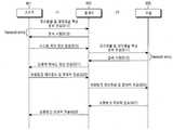
도 9는 본 발명의 실시 예에 따른 투명 중계를 수행하기 위한 다중 홉 릴레이 방식의 셀룰러 네트워크의 동작 절차를 도시하는 도면,9 is a diagram illustrating an operation procedure of a multi-hop relay-type cellular network for performing transparent relaying according to an embodiment of the present invention;
도 10은 본 발명의 실시 예에 따른 중계국 장치의 송신 방식을 도시하는 도면,10 is a diagram illustrating a transmission scheme of a relay station apparatus according to an embodiment of the present invention;
도 11은 본 발명에 따른 투명 중계를 수행하기 위한 기지국의 블록 구성을 도시하는 도면, 및11 is a block diagram of a base station for performing transparent relay according to the present invention; and
도 12는 본 발명에 따른 투명 중계를 수행하기 위한 중계국의 블록 구성을 도시하는 도면.12 is a block diagram of a relay station for performing transparent relaying according to the present invention;
본 발명은 다중홉 릴레이(Multi-hop Relay) 셀룰러 네트워크(Cellular Network)에 관한 것으로서, 특히 상기 다중홉 릴레이 셀룰러 네트워크에서 복수의 주파수 대역을 이용하여 투명하게 중계서비스를 수행하기 위한 장치 및 방법에 관한 것이다.The present invention relates to a multi-hop relay cellular network, and more particularly, to an apparatus and method for transparently performing a relay service using a plurality of frequency bands in the multi-hop relay cellular network. will be.
4세대 이동통신 시스템에서는 고속 통신을 가능하게 하고 더 많은 통화량을 수용하기 위하여 반경이 매우 작은 셀들이 설치된다. 이 경우에는 현재의 무선망 설계 방식을 그대로 사용한 중앙 집중적인 설계가 불가능해질 것이다. 이러한 무선 네트워크는 분산적으로 제어되고 구축되면서도, 새로운 기지국(Base station)의 추가와 같은 환경 변화에 능동적으로 대처할 수 있어야 한다. 상술한 이유로 4세대 이동통신 시스템에서는 자율적 적응형 무선 네트워크의 구성이 요구된다.In the fourth generation mobile communication system, very small radius cells are installed to enable high-speed communication and to accommodate more traffic. In this case, centralized design using the current wireless network design method will not be possible. While such wireless networks must be distributed and controlled, they must be able to actively respond to environmental changes, such as the addition of new base stations. For the reasons described above, the 4G mobile communication system requires the configuration of an autonomous adaptive wireless network.
삭제delete
삭제delete
상기 4세대 이동통신 시스템에서 요구되는 상기 자율적 적응형 무선 네트워크를 현실적으로 구현하기 위해서는 상기 Ad hoc 네트워크에서 적용된 기술을 이동통신 시스템에 도입해야 한다. 상기의 대표적인 사례가 다중홉 릴레이 (Multi-hop relay) 셀룰러 네트워크로서, 고정 기지국으로 구성된 셀룰러 네트워크에 Ad hoc 네트워크에서 적용된 기술인 다중홉 릴레이 기법을 도입한 것이다. 상기 셀룰러 네트워크에서는 기지국과 단말기(Mobile station) 간에 하나의 직접 링크(direct link)로 통신이 이루어지므로, 상기 단말기와 기지국 간에 신뢰도가 높은 무선 통신링크를 쉽게 구성할 수 있다.In order to realistically implement the autonomous adaptive wireless network required in the fourth generation mobile communication system, the technology applied in the ad hoc network should be introduced into the mobile communication system. A representative example of the above is a multi-hop relay cellular network, in which a multi-hop relay scheme, which is a technology applied in an ad hoc network, is introduced to a cellular network composed of fixed base stations. In the cellular network, since a communication is performed through a direct link between a base station and a mobile station, a reliable wireless communication link can be easily configured between the terminal and the base station.
그러나, 기지국의 위치가 고정되어 있으므로 무선망 구성의 유연성(flexibility)이 낮아 트래픽 분포나 통화 요구량의 변화가 심한 무선환경에서 효율적인 서비스를 제공하기 어렵다. 이와 같은 단점을 극복하기 위해 주변의 여러 단말기 또는 고정 중계국(Relay station)들을 이용하여 다중 홉 형태로서 데이터를 전달하는 중계국법을 적용한다. 또한, 상기 다중홉 릴레이 기법은 주변 환경변화에 대해 빠르게 네트워크를 재구성할 수 있으며, 전체 무선망을 보다 효율적으로 운용할 수 있게 된다.However, since the location of the base station is fixed, it is difficult to provide an efficient service in a wireless environment in which the traffic distribution or the call demand is changed due to low flexibility of the wireless network configuration. In order to overcome this drawback, a relay station method of transmitting data in the form of a multi-hop form by using a plurality of neighboring terminals or fixed relay stations is applied. In addition, the multi-hop relay scheme can quickly reconfigure the network for changes in the surrounding environment, it is possible to operate the entire wireless network more efficiently.
또한, 상기 다중 홉 중계 기법은 상기 기지국과 단말 사이에 중계기을 설치하여 상기 중계기을 통한 다중 홉 중계 경로를 구성함으로써, 채널 상태가 보다 우수한 무선 채널을 상기 단말에 제공할 수 있다. 더욱이 상기 다중 홉 중계 경로를 이용하여 음영 지역과 같이 상기 기지국과 통신을 수행할 수 없는 지역의 단말들에 고속의 데이터 채널을 제공할 수 있어, 셀 영역을 확장시킬 수 있다.In the multi-hop relay scheme, a repeater may be installed between the base station and the terminal to configure a multi-hop relay path through the repeater, thereby providing a wireless channel having a better channel state to the terminal. Furthermore, by using the multi-hop relay path, it is possible to provide a high-speed data channel to terminals in an area where communication with the base station is not possible, such as a shaded area, thereby expanding the cell area.
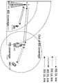
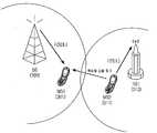
도 1은 일반적인 다중 홉 릴레이 방식 셀룰러 네트워크의 구성을 도시하고 있다.1 shows a configuration of a typical multi-hop relay cellular network.
상기 도 1에 도시된 바와 같이 기지국(100)의 서비스 영역(101)에 포함되는 단말(110)은 상기 기지국(100)과 직접 링크로 연결된다. 반면에, 상기 기지국의 서비스 영역(101) 밖에 위치하여 채널 상태가 열악한 단말(120)은 중계국(130)을 통해 중계 링크로 연결된다.As illustrated in FIG. 1, the
즉, 상기 기지국(100)은 상기 단말들(110, 120)이 상기 기지국의 서비스 영역(101)의 외곽에 위치하거나, 건물 등에 의해 차폐현상이 심한 음영지역에 위치하여 채널 상태가 열악할 경우, 상기 중계기(130)를 이용하여 상기 단말들(110, 120)에 더욱 우수한 무선 채널을 제공할 수 있다. 따라서, 상기 기지국(100)은 상기 다중 홉 중계 기법을 적용하여 채널 상태가 열악한 셀 경계지역에서 고속의 데이터 채널을 제공할 수 있으며, 상기 셀 서비스 영역을 확장시킬 수 있다.That is, the
다시 말해, 상기 중계국(130)은 상기 기지국(100)으로부터 하향링크 신호를 수신하여 상기 단말 2(120)로 중계한다. 또한, 상기 단말 2(120)로부터 상향링크 신호를 수신하여 상기 기지국(100)으로 중계한다. 따라서, 상기 다중 홉 중계방식의 셀룰러 네트워크는 상기 기지국(100)과 중계국(130) 사이의 BS-RS 링크와 상기 중계국(130)과 단말 2(120) 사이의 RS-MS 링크, 상기 기지국(100)과 단말 1(110) 사이의 BS-MS 링크가 형성된다. 이때, 각 링크는 데이터 전송 경로와 종단에 따라 상향링크 하향링크로 구분된다.In other words, the
상기 중계국(130)은 상기 기지국(100)의 서비스 영역 밖에 위치하는 단말 2(120)와 상기 기지국(100) 사이에 통신이 수행될 수 있도록 트래픽 전송뿐만 아니라, 초기 접속 등의 제어 정보도 중계해야 한다. 따라서, 상기 중계국(130)은 상기 단말이 다른 추가 기능이 없이 통신을 수행할 수 있도록 중계서비스를 제공해야 한다.
만일, 상기 기지국(100)이 하기 도 2에 도시된 바와 같은 프레임 구조를 이용하여 상기 단말 1(110)과 통신을 수행하는 경우, 상기 중계국(130)도 상기 기지국(100)과 동일한 프레임 구조 및 정보를 포함하여 상기 단말 2(120)에 신호를 중계해야 한다.
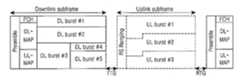
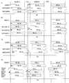
도 2는 일반적인 광대역 무선 접속 통신시스템의 프레임 구조를 도시하고 있다. 여기서, 상기 도 2는 IEEE(Institute of Electrical and Electronics Engineers) 802. 16에서 제공되는 시분할 복신(Time Division Duplex) 프레임 구조를 도시하고 있다.
상기 도 2에 도시된 바와 같이 상기 프레임은 시간 자원으로 하향링크 부프레임과 상향링크 부프레임으로 구분되어 구성된다. 여기서, 상기 하향링크 부프레임은 동기 채널, 제어 채널 및 하향링크 버스트로 순차적으로 구성된다. 상기 상향링크 부프레임은 제어 채널과 상향링크 버스트로 순차적으로 구성된다.The
If the
2 illustrates a frame structure of a general broadband wireless access communication system. 2 illustrates a time division duplex frame structure provided by Institute of Electrical and Electronics Engineers (IEEE) 802. 16. FIG.
As shown in FIG. 2, the frame is divided into a downlink subframe and an uplink subframe as time resources. Here, the downlink subframe is sequentially configured of a synchronization channel, a control channel, and a downlink burst. The uplink subframe consists of a control channel and an uplink burst sequentially.
상술한 바와 같이 상기 중계 서비스를 제공받는 단말의 입장에서 추가기능 없이 상기 중계국을 이용한 통신을 수행하기 위한 기능이 요구되고 있다. 즉 상기 중계국에서 투명하게 신호를 중계하기 위한 기능이 요구되고 있다.As described above, from the standpoint of the terminal receiving the relay service, a function for performing communication using the relay station without additional functions is required. In other words, a function for transparently relaying signals at the relay station is required.
따라서, 본 발명의 목적은 다중 홉 릴레이 방식의 셀룰러 네트워크에서 신호를 투명(Transparent)하게 중계하기 위한 장치 및 방법을 제공함에 있다.Accordingly, an object of the present invention is to provide an apparatus and method for transparently relaying signals in a multi-hop relay cellular network.
본 발명의 다른 목적은 다중 홉 릴레이 방식의 셀룰러 네트워크에서 중계국은 다수 개의 주파수 대역을 이용하여 투명하게 중계를 수행하기 위한 장치 및 방법을 제공함에 있다.Another object of the present invention is to provide an apparatus and method for transparently performing relaying using a plurality of frequency bands in a multi-hop relay cellular network.
상기 목적들을 달성하기 위한 본 발명의 제 1 견지에 따르면, 다중 홉 릴레이(Multi-hop Relay) 방식의 셀룰러 네트워크(Cellular Network)에서 중계서비스를 지원하기 위한 중계국의 동작 방법은, 제 1 주파수 대역을 이용하여 상위 노드와 통신을 수행하는 과정과, 제 2 주파수 대역을 이용하여 하위 노드와 통신을 수행하는 과정을 포함하는 것을 특징으로 한다.According to a first aspect of the present invention for achieving the above objects, a method for operating a relay station for supporting a relay service in a cellular network of a multi-hop relay scheme includes a first frequency band. And communicating with the upper node using the second node, and communicating with the lower node using the second frequency band.
본 발명의 제 2 견지에 따르면, 다중 홉 릴레이(Multi-hop Relay) 방식의 셀룰러 네트워크(Cellular Network)의 중계국에서 중계서비스를 지원하기 위한 장치는, 해당 링크의 사용 주파수 대역을 이용하여 신호를 송수신하기 위한 타이밍 신호를 제공하는 타이밍 제어기와, 상기 타이밍 신호에 따라 제 1 주파수 대역을 이용하여 상위 노드와 통신을 수행하는 제 1 송수신 장치와, 상기 타이밍 신호에 따라 제 2 주파수 대역을 이용하여 하위 노드와 통신을 수행하는 제 2 송수신 장치를 포함하는 것을 특징으로 한다.According to a second aspect of the present invention, an apparatus for supporting a relay service in a relay station of a cellular network of a multi-hop relay (Multi-hop Relay) type, transmits and receives a signal using a used frequency band of the link. A timing controller for providing a timing signal for performing the communication; a first transmitting / receiving device for communicating with an upper node using a first frequency band according to the timing signal; and a lower node using a second frequency band according to the timing signal. And a second transmission / reception apparatus for performing communication with the.
이하 본 발명의 바람직한 실시 예를 첨부된 도면을 참조하여 상세히 설명한다. 그리고, 본 발명을 설명함에 있어서, 관련된 공지기능 혹은 구성에 대한 구체적인 설명이 본 발명의 요지를 불필요하게 흐릴 수 있다고 판단된 경우 그 상세한 설명은 생략한다.Hereinafter, exemplary embodiments of the present invention will be described in detail with reference to the accompanying drawings. In describing the present invention, when it is determined that a detailed description of a related known function or configuration may unnecessarily obscure the subject matter of the present invention, the detailed description thereof will be omitted.
이하 본 발명은 다중 홉 릴레이(Multi-hop Relay) 셀룰러 네트워크(Cellular Network)에서 다수 개의 주파수 대역을 이용하여 투명(Transparent)하게 중계 서비스를 제공하기 위한 기술에 대해 설명한다. 다시 말해, 상기 셀룰러 네트워크는 투명 중계 서비스를 제공하기 위해 다수 개의 주파수 대역을 이용하며, 상기 기지국과 중계국 링크와 중계국과 단말 링크가 서로 다른 주파수 대역을 통해 통신이 수행되는 방식에 대해 설명한다. 여기서, 상기 투명 중계 서비스는, 상기 중계 서비스를 제공받는 단말의 입장에서 중계국을 통해 제공받는 서비스를 중계 서비스로 인식하지 못하고, 기지국으로부터 직접 서비스를 제공받는 것으로 인식하여 통신을 수행하도록 하는 것을 의미한다.Hereinafter, the present invention describes a technique for transparently providing a relay service using a plurality of frequency bands in a multi-hop relay cellular network. In other words, the cellular network uses a plurality of frequency bands to provide a transparent relay service, and the base station, the relay station link, and the relay station and the terminal link will be described how communication is performed through different frequency bands. Here, the transparent relay service means that the mobile terminal does not recognize the service provided through the relay station as a relay service from the standpoint of the terminal receiving the relay service and performs communication by recognizing that the service is directly provided by the base station. .
이하 설명은, 시분할 복신(Time Division Duplex) 및 직교주파수 분할 다중 접속(Orthogonal Frequency Division Multiplexing Access) 방식을 사용하는 무선통신시스템을 예를 들어 설명하며, 다른 다중 접속 방식에도 동일하게 적용 가능하다. 또한, 상기 기지국과 단말 사이의 링크를 직접 링크라 칭하고, 상기 기지국과 중계국과의 링크는 중계 링크라 칭하며, 상기 중계국과 단말과의 링크는 서브-셀(Sub-Cell) 링크라 칭한다.In the following description, a wireless communication system using Time Division Duplex and Orthogonal Frequency Division Multiplexing Access is described as an example, and the same can be applied to other multiple access schemes. In addition, the link between the base station and the terminal is called a direct link, the link between the base station and the relay station is called a relay link, and the link between the relay station and the terminal is called a sub-cell link.
도 3은 본 발명에 따른 투명 중계를 수행하기 위한 다중 홉 릴레이 셀룰러 네트워크의 구성을 도시하고 있다. 이하 설명은 두 홉 중계 방식에서 두 개의 주파수 대역을 사용하여 신호를 투명하게 중계하는 것을 가정하여 설명한다.3 illustrates the configuration of a multi-hop relay cellular network for performing transparent relay in accordance with the present invention. In the following description, it is assumed that a signal is transparently relayed using two frequency bands in a two-hop relay method.
상기 도 3에 도시된 바와 같이 기지국(300)의 서비스 영역에 포함되는 단말들(301, 303)은 상기 기지국(300)과 직접 링크로 연결된다. 하지만, 상기 기지국(300)의 서비스 영역 밖에 위치하는 단말들(311, 313)은 중계국(310)을 통한 중계 링크로 상기 기지국(300)과 연결된다.As illustrated in FIG. 3, the
이때, 상기 기지국(300)은 두 개의 주파수 대역(F1, F2)을 이용하여 상기 단말들(301, 303)과 통신을 수행하고, 상기 F1 주파수 대역을 이용하여 중계국(310)과 통신을 수행한다. 여기서, 상기 기지국(300)은 상기 중계국 사이의 링크 제어 채널을 통해 상기 중계국(310)의 동작을 제어한다.In this case, the
한편, 중계국(310)은 상기 F1 주파수 대역을 통해 상기 기지국(300)으로부터 수신받은 신호들 중 중계가 필요한 신호들만을 선택한다. 이후, 상기 중계국(310)은 상기 선택한 신호들을 F2 주파수 대역을 이용하여 상기 단말들(311, 313)로 중계한다. 여기서, 상기 중계국(310)은 상기 기지국(300)의 제어에 따라 상기 중계가 필요한 신호들을 선택한다.On the other hand, the
또한, 상기 중계국(310)이 상기 단말들(311, 313)의 신호를 중계하는 경우, 상기 중계국(310)은 상기 단말들(311, 313)이 상기 기지국(300)에 초기 접속(Initial Access)(예 : 네트워크 진입(Network Entry))이 가능하도록 F2주파수 대역을 이용하여 초기 접속에 따라 요구되는 기능들을 제공해야한다. 즉, 상기 중계국(310)은 상기 단말들(311, 313)에게 방송(Broadcasting) 형태로 전송되는 단방향 제어 채널신호 또는 트래픽 채널(Traffic Channel)신호를 상기 F2 주파수 대역을 이용하여 중계한다. 또한, 상기 중계국(310)은 상기 단말들(311, 313)이 초기 접속을 위해 전송하는 랜덤 접속 채널(Random Access Channel) 신호를 상기 F2 주파수 대역을 이용하여 상기 기지국(300)으로 중계한다.In addition, when the
따라서, 상기 중계국(310)은 서로 다른 주파수 대역(F1, F2)을 이용하여 두 개의 링크(기지국과 중계국 링크, 중계국과 단말 링크)의 통신을 수행한다.Accordingly, the
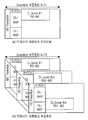
도 4는 본 발명의 실시 예에 따른 투명 중계를 위한 하향링크 부프레임 구조를 도시하고 있다. 이하 설명은 도 3에서 사용되는 F1과 F2 주파수 대역을 이용한 하향링크 부프레임의 구조를 예를 들어 설명한다. 여기서, 상기 하향링크 부프레임을 예를 들어 설명하지만, 상향링크 부프레임도 동일한 형태를 갖는다.4 illustrates a downlink subframe structure for transparent relay according to an embodiment of the present invention. Hereinafter, the structure of a downlink subframe using the F1 and F2 frequency bands used in FIG. 3 will be described as an example. Here, the downlink subframe will be described as an example, but the uplink subframe has the same form.
상기 도 4를 참조하면, 상기 도 4의 (a)는 상기 F1 주파수 대역을 이용한 하향링크 부프레임의 구조를 도시하고, 상기 도 4의 (b)는 상기 F2 주파수 대역을 이용한 하향링크 부프레임의 구조를 도시하고 있다.Referring to FIG. 4, FIG. 4A shows a structure of a downlink subframe using the F1 frequency band, and FIG. 4B shows a structure of a downlink subframe using the F2 frequency band. The structure is shown.
먼저 상기 도 4의 (a)에 도시된 바와 같이 상기 F1 주파수 대역의 하향링크 부프레임은 상기 기지국(300)이 상기 단말들(301, 303) 및 중계국(310)으로 신호를 전송하기 위한 하향링크 부프레임으로 구성된다.First, as shown in (a) of FIG. 4, the downlink subframe of the F1 frequency band is a downlink for the
다음으로 상기 도 4의 (b)에 도시된 바와 같이 상기 F2 주파수 대역의 하향링크 부프레임은 상기 기지국(300)이 상기 단말들(301, 303)로 하향링크 신호를 전송하기 위한 제 1 하향링크 부프레임과 상기 중계국(310)의 상기 단말들(311, 313)로 하향링크 신호를 중계하기 위한 제 2 하향링크 부프레임으로 구성된다. 이때, 상기 제 1 하향링크 부프레임과 제 2 하향링크 부프레임은 공간 자원으로 다중화되어 구성된다. 여기서 상기 F2 주파수 대역을 통해 기지국(300)은 단말들(301, 303)과 통신하고, 상기 중계국(310)은 자신의 서브셀 링크를 통해 단말들(311, 313)과 통신한다.Next, as illustrated in (b) of FIG. 4, the downlink subframe of the F2 frequency band includes a first downlink for transmitting the downlink signal to the
상술한 바와 같이 시분할 복신 방식의 다중 홉 릴레이 방식의 셀룰러 네트워크에서 다수 개의 주파수 대역을 사용하여 투명하게 신호를 중계하는 경우, 상기 도 4에 도시된 바와 같이 동일 주파수 대역을 공간 다중화 형태로 다중화되어 사용되므로 인접 셀의 간섭을 배제하기 위한 시간 동기화가 이루어 져야한다. 만일, 상기 시간 동기화가 이루어지지 않으면, 상기 셀룰러 네트워크는 하기 도 5에 도시된 바와 같이 직접 링크와 서브 셀 링크 사이에 역방향 링크의 간섭이 발생한다. 여기서 역방향 링크의 간섭은, 상향링크 신호가 인접 셀의 하향링크 신호에 큰 전력 세기로의 간섭을 의미한다.As described above, when a signal is transparently relayed using a plurality of frequency bands in a multi-hop relay cellular network in time division duplex, the same frequency band is multiplexed in a spatial multiplexed form as shown in FIG. 4. Therefore, time synchronization must be made to exclude interference of neighbor cells. If the time synchronization is not achieved, the cellular network generates reverse link interference between the direct link and the sub cell link as shown in FIG. 5. In this case, the interference of the reverse link means that the uplink signal interferes with the downlink signal of the adjacent cell at a large power intensity.
도 5는 본 발명의 실시 예에 따른 역방향 링크의 간섭이 발생하는 다중 홉 릴레이 방식 셀룰러 네트워크의 구성을 도시하고 있다.FIG. 5 illustrates a configuration of a multi-hop relay cellular network in which reverse link interference occurs according to an embodiment of the present invention.
상기 도 5에 도시된 바와 같이 상기 기지국(300)은 F2 주파수 대역을 이용하여 단말 1(301)과 직접링크를 통해 통신을 수행하고, 상기 중계국(310)도 상기 F2 주파수 대역을 이용하여 단말 2(311)와 중계링크를 통해 통신을 수행한다. 이때, 동일한 주파수 대역을 사용하는 상기 기지국과 단말 1 링크의 프레임과 상기 중계국과 단말 2 링크의 프레임의 동기가 맞지 않으면, 각 링크의 신호들이 간섭으로 작용하여 시스템 성능이 크게 열화 된다.As shown in FIG. 5, the
따라서, 상기 다중 홉 릴레이 방식의 셀룰러 네트워크에서 중계국은 역방향 링크에 의한 간섭을 배제하기 위해 하기 도 6에 도시된 바와 같이 기지국과 중계국 사이의 전송 지연을 고려하여 타이밍 전진(Timing Advance)을 수행하여 중계하는 방식을 사용한다.Therefore, in the multi-hop relay cellular network, the relay station performs timing advance considering timing of transmission delay between the base station and the relay station in order to exclude the interference caused by the reverse link. Use the way.
도 6은 본 발명의 실시 예에 따른 다중 홉 릴레이 방식 셀룰러 네트워크에서 역방향 링크의 간섭을 방지하기 위한 송신 타이밍을 도시하고 있다.6 illustrates transmission timing for preventing reverse link interference in a multi-hop relay cellular network according to an embodiment of the present invention.
상기 도 6을 참조하면, 상기 도 6의 (a)는 F1 주파수 대역에서의 타이밍을 도시하고, 상기 도 6의 (b)는 F2 주파수 대역에서의 타이밍을 도시하고 있다. 또한, 상기 도 6의 (c)와 상기 도 6의 (d)는 잘못된 타이밍 전진으로 인해 발생하는 역방향 링크의 간섭을 나타낸다. 여기서, 하나의 프레임은 하향링크, TTG(Transmit/Receive Transition Gap), 상향링크, RTG(Receive/Transmit Transition Gap)를 포함하여 구성된다.Referring to FIG. 6, FIG. 6A illustrates timing in the F1 frequency band, and FIG. 6B illustrates timing in the F2 frequency band. 6 (c) and 6 (d) show the interference of the reverse link due to incorrect timing advancement. Here, one frame includes a downlink, a transmit / receive transition gap (TGT), an uplink, and a receive / transmit transition gap (RTG).
먼저, 상기 도 6의 (a)에 도시된 바와 같이 상기 기지국이 F1 주파수 대역을 통해 하향링크 부프레임을 전송하면(601), 상기 기지국으로부터 F1 주파수 대역을 통해 통신을 수행하는 단말 혹은 중계국은 전송 지연된 상기 기지국의 하향링크 부프레임을 수신한다(603). 이후, 상기 RTD(Round Trip Delay)를 고려하여 타이밍 전진하여 상기 기지국 상향링크 부프레임을 상기 기지국으로 송신한다(605).First, as shown in (a) of FIG. 6, when the base station transmits a downlink subframe through the F1 frequency band (601), the terminal or relay station performing communication from the base station through the F1 frequency band is transmitted. The downlink subframe of the base station is delayed (603). Thereafter, the timing advances in consideration of the RTD (Round Trip Delay) and transmits the base station uplink subframe to the base station (605).
다음으로 상기 도 6의 (b)에 도시된 바와 같이 상기 기지국이 하향링크 부프레임을 전송하면(611), 상기 중계국은 상기 기지국의 전송지연을 고려하여 0.5×RTD 만큼 타이밍 전진하여 상기 중계국 하향링크 부프레임을 단말로 전송한다(613). 여기서, 상기 0.5×RTD 만큼 타이밍 전진을 수행함으로써, 상기 도 6의 (c)에 도시된 바와 같이 타이밍 전진을 하지 않는 경우, 상기 중계국의 하향링크 부프레임내의 신호가 경험하는 F2 주파수 대역에서 상기 기지국과 직접링크를 갖는 단말의 상향링크 부프레임내의 신호로부터의 큰 크기의 간섭을 방지할 수 있다. 또한, 상기 도 6의 (d)에 도시된 바와 같이 중계국이 F1 주파수 대역에서의 통신 링크에서와 같이 F2 주파수 대역에서도 송신 신호를 RTD만큼 타이밍 전진하는 경우, 상기 중계국의 상향링크 부프레임내의 신호가 상기 기지국 하향링크 부프레임 신호에 간섭을 발생시킴을 보여주고 있다.Next, as shown in (b) of FIG. 6, when the base station transmits a downlink subframe (611), the relay station advances the timing by 0.5 × RTD in consideration of the transmission delay of the base station and downlinks the relay station. The subframe is transmitted to the terminal (613). Here, by performing the timing advance by the 0.5 × RTD, when the timing is not advanced as shown in (c) of FIG. 6, the base station in the F2 frequency band experienced by the signal in the downlink subframe of the relay station It is possible to prevent a large amount of interference from the signal in the uplink subframe of the terminal having a direct link and the. Further, as shown in FIG. 6 (d), when the relay station advances the transmission signal by RTD in the F2 frequency band as in the communication link in the F1 frequency band, the signal in the uplink subframe of the relay station is It shows that the interference occurs in the base station downlink subframe signal.
상술한 바와 같이 두 홉으로 구성된 셀룰러 네트워크에서 서로 다른 주파수 대역을 이용하여 중계링크와 서브셀 링크를 설정하는 방법은 상기 두 홉뿐만 아니라 하기 도 7에 도시된 바와 같이 다중 홉으로 확장이 가능하다. 이때, 상기 두 홉에서의 기지국은 상위 노드로 기지국 또는 상위 중계국이 될 수 있다.As described above, the method of configuring a relay link and a subcell link using different frequency bands in a cellular network composed of two hops may be extended to multiple hops as shown in FIG. 7 as well as the two hops. At this time, the base station in the two hops may be a base station or an upper relay station to the upper node.
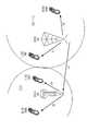
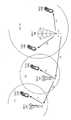
도 7은 본 발명의 실시 예에 따른 투명 중계를 수행하며 확장된 다중 홉 릴레이 셀룰러 네트워크의 구성을 도시하고 있다.7 illustrates a configuration of an extended multi-hop relay cellular network performing transparent relaying according to an embodiment of the present invention.
상기 도 7에 도시된 바와 같이 기지국(700)은 서비스 영역에 포함되는 단말들(701, 703)과 두 개의 주파수 대역(F1, F2)을 이용하여 통신을 수행한다. 또한, 중계국 1(710)과는 F1 주파수 대역을 이용하여 통신을 수행한다.As illustrated in FIG. 7, the
상기 중계국 1(710)은 F1 주파수 대역을 통해 상기 기지국(700)과 통신을 수행한다. 또한, 상기 중계국 1(710)은 투명 중계를 수행하기 위해 상기 F1 주파수 대역과 다른 F2 주파수 대역을 이용하여 상기 중계국(710)의 서브셀 영역에 포함되는 단말(711) 및 중계국 2(720)와 서브셀 링크 및 2 홉 중계링크를 형성하여 통신을 수행한다.The
상기 중계국 2(720)는 상기 F2 주파수 대역을 통해 상기 중계국 1(710)과 중계 링크로 통신을 수행한다. 또한, 상기 중계국 2(720)는 상기 F1 주파수 대역을 이용하여 상기 중계국 2(720)의 서브 셀에 포함되는 단말(721)과 서브셀 링크를 형성하여 통신을 수행한다.
상술한 바와 같아 상기 셀룰러 네트워크에서 각 홉마다 주파수를 교차하여 할당함으로써 다중 홉으로도 확장할 수 있다. 상기 실시 예에서는 최종 말단의 중계국까지 2 홉을 가정하였다. 3 홉으로의 확장을 고려한다면 상기 기지국(700)이 단일 홉의 중계국으로 대치될 수 있고, 상기 중계국(710)이 2 홉 중계국으로 대치되어 동작한다. 즉, 일반적으로 이전 홉의 중계국과 다음 홉의 중계국 사이의 동작은 상기 도 7의 단일 홉 중계국(710)과 2 홉 중계국(720) 사이와 동일하게 동작한다.
As described above, the cellular network can be extended to multiple hops by alternately allocating frequencies for each hop. In the above example, it is assumed that two hops to the last terminal relay station. Considering the expansion to three hops, the
이하 설명은 상기 다수 개의 주파수 대역을 사용하여 기지국과 단말의 신호 를 투명하게 중계하기 위한 중계국 및 다중 홉 릴레이 방식의 셀룰러 네트워크의 동작 절차에 대해 설명한다.Hereinafter, a description will be given of an operation procedure of a relay station and a multi-hop relay cellular network for transparently relaying signals of a base station and a terminal using the plurality of frequency bands.
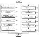
도 8은 본 발명의 실시 예에 따른 투명 중계를 수행하기 위한 중계국의 동작 절차를 도시하고 있다. 이하 설명은 두 개의 주파수 대역을 사용하여 신호를 투명하게 중계하는 것을 가정하여 설명하며, 다수 개의 주파수 대역을 사용하는 것으로 확장 가능하다. 또한, 상기 중계국은 중계링크에 사용되는 F1 주파수 대역과 서브셀 링크에 사용되는 F2 주파수 대역을 동시에 사용한다. 즉, 중계링크와 서브셀 링크는 서로 다른 주파수 대역을 사용한다.8 illustrates an operation procedure of a relay station for performing transparent relaying according to an embodiment of the present invention. The following description is based on the assumption that a signal is transparently relayed using two frequency bands, and can be extended to using a plurality of frequency bands. In addition, the relay station simultaneously uses the F1 frequency band used for the relay link and the F2 frequency band used for the subcell link. That is, the relay link and the subcell link use different frequency bands.
상기 도 8을 참조하면 상기 중계국은 F1 주파수 대역과 F2 주파수 대역을 병렬로 사용하여 중계 링크 및 서브셀 링크와 동시에 통신을 수행한다. 즉, 상기 중계국은 상기 F1 주파수 대역을 사용하는 중계링크를 통해 기지국으로부터 신호를 수신하고, 상기 F2 주파수 대역을 사용하는 서브셀 링크를 통해 단말로 신호를 송신한다.Referring to FIG. 8, the RS uses the F1 frequency band and the F2 frequency band in parallel to simultaneously communicate with the relay link and the subcell link. That is, the relay station receives a signal from a base station through a relay link using the F1 frequency band and transmits a signal to a terminal through a subcell link using the F2 frequency band.
먼저, 상기 F1 주파수 대역에서의 상기 중계국 동작 절차에 대해 살펴보면, 상기 중계국은 801단계에서 상기 기지국으로부터 프리앰블 신호를 수신하여 동기화 정보를 획득한다. 여기서, 상기 중계국은 상기 기지국에 대해 하나의 단말처럼 동작한다.First, the operation of the RS in the F1 frequency band will be described. The RS receives the preamble signal from the BS in step 801 to obtain synchronization information. Here, the relay station acts as one terminal for the base station.
상기 기지국으로부터 동기화 정보를 획득하면, 상기 중계국은 803단계로 진행하여 상기 중계를 위한 제어 정보를 획득한다. 즉, 상기 중계국은 FCH(Frame Control Header)와 DL(Down Link) MAP 및 UL(Up Link) MAP 정보를 수신하여 상기 중계국의 서브 셀에 포함되는 단말들로 신호를 중계하기 위한 제어 정보를 획득한다.When the synchronization information is obtained from the base station, the relay station proceeds to step 803 to obtain control information for the relay. That is, the RS receives frame control header (FCH), downlink (DL) MAP and uplink (UL) MAP information to obtain control information for relaying signals to terminals included in the subcell of the RS. .
상기 중계 제어 정보를 획득한 후, 상기 중계국은 805단계로 진행하여 상기 중계 제어 정보에 따라 상기 기지국으로부터 상기 서브셀에 포함되는 단말로 중계를 수행할 트래픽 신호를 수신한다.After obtaining the relay control information, the RS proceeds to step 805 to receive a traffic signal for relaying from the base station to a terminal included in the subcell according to the relay control information.
이후, 상기 중계국은 807단계에서 상기 기지국의 하향링크 신호를 수신하는 수신모드에서 송신모드로 제 1 동작 전환을 수행한다. 여기서, 상기 F1 주파수 대역에서 전송 모드가 수신모드에서 송신모드로 전환되는 제 1 동작 전환이 수행되면, 상기 F2 주파수 대역의 전송 모드는 송신모드에서 수신모드로 전환된다.In
상기 제 1 동작전환을 수행한 후, 상기 중계국은 809단계로 진행하여 RTD 만큼 타이밍 전진을 수행하여 상기 이전 타임에 F2 주파수 대역을 통해 단말로부터 수신된 상향링크 신호를 상기 기지국으로 송신한다.After performing the first operation switch, the RS proceeds to step 809 to perform timing advance by RTD to transmit an uplink signal received from the UE through the F2 frequency band to the base station at the previous time.
이후, 상기 중계국은 811단계로 진행하여 상기 송신 모드에서 수신모드로 제 2 동작 전환을 수행한 후, 상기 중계국은 본 알고리즘을 종료하거나 다음 프레임 수신을 위해 상기 803단계로 되돌아간다.Thereafter, the relay station proceeds to step 811 to perform the second operation switch from the transmission mode to the reception mode, and then the relay station ends the algorithm or returns to step 803 to receive the next frame.
다음으로 F2주파수 대역에서의 상기 중계국의 동작 절차를 살펴보면, 상기 중계국은 802단계에서 상기 기지국의 하향링크 부프레임의 송신 타이밍과 동일하게 프리앰블 신호를 상기 서브셀 영역에 전송한다. 즉, 상기 중계국은 상기 기지국의 하향링크 부프레임의 송신 타이밍과 지연시간을 고려하여, 0.5×RTD 만큼 타이밍 전진하여 전송한다.Next, referring to an operation procedure of the RS in the F2 frequency band, the RS transmits a preamble signal to the subcell area in the same manner as the transmission timing of the DL subframe of the BS in
상기 프리앰블 신호를 전송한 후, 상기 중계국은 804단계와 806단계에 걸쳐 공통 제어 정보 및 상기 기지국으로부터 수신된 중계 트래픽을 상기 단말로 전송한다.After transmitting the preamble signal, the relay station transmits common control information and relay traffic received from the base station to the terminal in
이후, 상기 중계국은 808단계로 진행하여 상기 단말로 하향링크 신호를 송신 하는 송신모드에서 수신모드로 제 1 동작 전환을 수행한다. 여기서, 상기 F2 주파수 대역에서 전송 모드가 송신모드에서 수신모드로 전환되면, 상기 F1 주파수 대역의 전송모드는 수신모드에서 송신모드로 전환된다.Thereafter, the RS proceeds to step 808 to perform a first operation switch from a transmission mode for transmitting a downlink signal to the terminal to a reception mode. Here, when the transmission mode is switched from the transmission mode to the reception mode in the F2 frequency band, the transmission mode of the F1 frequency band is switched from the reception mode to the transmission mode.
상기 제 1 동작 전환을 수행한 후, 상기 중계국은 810단계로 진행하여 상기 단말로부터 상향링크 신호를 수신한다. 즉, 상기 기지국으로 중계할 상기 단말의 상향링크 신호를 수신한다.After performing the first operation switch, the RS proceeds to step 810 to receive an uplink signal from the terminal. That is, an uplink signal of the terminal to be relayed to the base station is received.
이후, 상기 중계국은 812단계로 진행하여 상기 단말로부터 신호를 수신하는 수신모드에서 송신모드로 전환한 후, 상기 중계국은 본 알고리즘을 종료하거나 다음 프레임 수신을 위해 상기 802단계로 되돌아간다.Thereafter, the relay station proceeds to step 812 and switches from the reception mode for receiving the signal to the transmission mode to the transmission mode, and then the relay station ends the algorithm or returns to the
도 9는 본 발명의 실시 예에 따른 투명 중계를 수행하기 위한 다중 홉 릴레이 방식의 셀룰러 네트워크의 동작 절차를 도시하고 있다.9 illustrates an operation procedure of a multi-hop relay cellular network for performing transparent relaying according to an exemplary embodiment of the present invention.
상기 도 9를 참조하면, 먼저 기지국(901)은 F1 주파수 대역을 이용하여 프리앰블 및 제어채널 특성 정보를 중계국(903)에 전송한다(911단계).9, the base station 901 first transmits the preamble and control channel characteristic information to the
상기 중계국(903)은 상기 기지국(901)으로부터 수신된 프리앰블 및 제어채널 특성 정보를 이용하여 시스템 동기를 획득하고, 하향링크 및 상향링크 제어 채널 특성 정보를 획득한다. 이후, 상기 중계국(903)은 상기 획득한 제어 채널 특성에 따라 F1 주파수 대역을 이용하여 상기 기지국(901)으로 접속 절차를 수행한다(913단계). 여기서, 상기 중계국(903)은 자신의 중계 능력을 상기 기지국(901)과의 통신을 통해 협상할 수 있다.The
이후, 상기 기지국(901)은 상기 접속된 중계국(903)으로 상기 중계국의 서브셀 영역에 포함되는 단말들에 서비스를 제공하기 위한 서브셀 링크에서 사용할 주파수 대역(F2) 정보를 포함하는 시스템 제어정보를 상기 중계국(903)으로 전송한다(915단계).Subsequently, the base station 901 includes system control information including frequency band (F2) information to be used in a subcell link for providing services to terminals connected to the
상기 중계국(903)은 상기 시스템 제어 정보가 수신되면, 상기 기지국(901)이 지정한 주파수 대역(F2)을 이용하여 상기 서브셀 영역에 포함되는 단말들을 위해 프리앰블 및 제어채널 특성 정보를 전송(방송)한다(917단계).When the system control information is received, the
상기 단말(905)은 상기 중계국(903)으로부터 수신된 프리앰블 및 제어채널 특성 정보를 이용하여 시스템 동기를 획득하고, 하향링크 및 상향링크 제어 채널 특성 정보를 획득한다. 이후, 상기 단말(905)은 상기 획득한 제어 채널 특성에 따라 F2 주파수 대역을 이용하여 상기 중계국(903)으로 접속 절차를 수행한다(919단계).The terminal 905 acquires system synchronization by using the preamble and control channel characteristic information received from the
상기 중계국(903)은 상기 단말(905)로부터 액세스 정보가 수신되면, 상기 단말(905)의 액세스 정보를 F1 주파수 대역을 이용하여 상기 기지국(901)으로 중계한다(921단계).When the
이후, 상기 기지국(901)은 F1 주파수 대역을 이용하여 상기 중계국(903)으로 중계 서비스를 제공받을 단말을 위한 하향링크 제어정보 및 트래픽을 전송한다(923단계). 여기서, 상기 하향링크 제어정보는 상기 중계국(903)이 중계가 필요한 신호들만을 선택할 수 있도록 제어하는 제어 정보를 포함한다.Thereafter, the base station 901 transmits downlink control information and traffic for the terminal to receive the relay service to the
상기 중계국(903)은 상기 F1 주파수 대역을 통해 상기 기지국(901)으로부터 수신된 제어정보 및 트래픽을 F2 주파수 대역을 이용하여 상기 단말(905)로 전송한다(925단계).The
또한, 상기 단말(905)이 F2 주파수 대역을 통해 상기 중계국(903)으로 상향링크 신호를 전송하고(927단계), 상기 중계국(903)은 상기 F2 주파수 대역을 통해 수신된 상기 단말(905)의 상향링크 신호를 F1 주파수 대역을 통해 상기 기지국(901)으로 전송한다(929단계).In addition, the terminal 905 transmits an uplink signal to the
상술한 바와 같이 중계국을 이용하여 신호를 중계함으로써 기지국의 서비스 영역을 확대할 수 있다. 그러나 상기 신호의 중계는 하향링크의 경우, 상기 중계국은 기지국의 하향링크 신호를 중계링크를 통해 수신한 후, 동일 정보를 재구성하여 서브셀 링크로 서비스하므로 무선 자원 측면에서 자원 효율을 저하시키게 된다. 또한, 상기 중계국은 상기 기지국의 서비스 영역을 확장하기 위해 상기 기지국의 셀 경계에 위치하는 경우, 상기 기지국과 중계국 사이의 중계링크를 통한 채널 용량이 낮아지게 되는 문제가 발생한다.As described above, the service area of the base station can be expanded by relaying signals using the relay station. However, when the signal is relayed in the downlink, the relay station receives the downlink signal of the base station through the relay link, and reconfigures the same information to serve as a subcell link, thereby reducing resource efficiency in terms of radio resources. In addition, when the relay station is located at a cell boundary of the base station in order to expand the service area of the base station, there occurs a problem that the channel capacity through the relay link between the base station and the relay station becomes low.
따라서, 본 발명은 상기 중계링크의 채널 용량을 증대시키면서, 상기 기지국 서비스 영역을 확장하기 위해 하기 도 10에 도시된 바와 같이 중계국은 방향성 안테나를 사용한다.
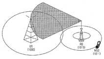
도 10은 본 발명의 실시 예에 따른 중계국 장치의 송신 방식을 도시하고 있다.
상기 도 10에 도시된 바와 같이 상기 중계국(1010)은 방향성 안테나를 사용하여 상기 기지국(1000)과 통신링크를 설정하여 상기 기지국과 중계국 사이의 중계링크의 채널 용량을 증대시킨다.
또한, 상기 중계국(1010)은 전방향 안테나를 사용하여 서브셀에 포함된 단말(1311)과 통신 링크를 설정하여 상기 기지국 서비스 영역을 확장한다. 즉, 상기 중계국은 기지국과 통신링크를 설정하기 위한 방향성 안테나와 단말과 통신링크를 설정하기 위한 전방향 안테나의 두 개의 RF(Radio Frequency) 단을 갖는다.Accordingly, the present invention uses a directional antenna as shown in Figure 10 to expand the base station service area while increasing the channel capacity of the relay link.
10 illustrates a transmission method of a relay station apparatus according to an embodiment of the present invention.
As shown in FIG. 10, the
In addition, the
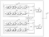
도 11은 본 발명에 따른 투명 중계를 수행하기 위한 기지국의 블록 구성을 도시하고 있다. 이하 설명은 두 개의 주파수 대역을 사용하는 것을 예를 들어 설명한다.11 is a block diagram of a base station for performing transparent relay in accordance with the present invention. The following description uses an example of using two frequency bands.
상기 도 11에 도시된 바와 같이 상기 기지국은, 두 개의 주파수 대역(F1, F2)을 이용하여 통신을 수행하기 때문에, F1 주파수 대역의 송수신 장치(1101)와 F2 주파수 대역의 송수신 장치(1103) 및 타이밍 제어기(1105)와 대역 통과 필터(Band Pass Filter)(1133, 1163)를 포함하여 구성된다. 여기서, 상기 F1 주파수 대역의 송수신 장치(1101)와 상기 F2 주파수 대역의 송수신 장치(1103)는 동일한 구성을 가지므로 상기 F1 주파수 대역의 송수신 장치(1101)만을 예를 들어 설명하며 상기 F2 주파수 대역의 송수신 장치(1103)도 동일한 구조를 갖는다.As shown in FIG. 11, since the base station communicates using two frequency bands F1 and F2, the base station transmits and receives an apparatus for transmitting and receiving an
대역 통과 필터(1133, 1163)는 서로 다른 주파수 대역을 이용하는 송수신 장치(1101, 1103)의 사용주파수 대역을 분리하여 각 송수신 장치(1101, 1103)에 전송한다.The
상기 F1 주파수 대역의 송수신 장치(1101)는, 상기 대역 통과 필터(1133)를 통해 상기 F1 주파수 대역의 신호를 송수신하기 위하여 송신장치(1111), 수신장치(1121) 및 RF스위치(1131)를 포함하여 구성된다.The
상기 송신 장치(1111)는 프레임 구성기(1113), 자원 매핑기(1115), 변조기 (1117), 및 디지털/아날로그 변환기(Digital/Analog Converter)(1119)를 포함하여 구성된다.The
프레임 구성기(1113)는 상위단으로부터 제공받은 데이터들을 목적지에 따라 각각의 부프레임을 생성한다. 예를 들어, 상기 프레임 구성기(1113)가 기지국에 포함될 경우, 상기 직접링크로 연결된 단말로 전송할 데이터를 이용하여 BS-MS 부프레임을 구성하고, 상기 중계기로 전송할 데이터를 이용하여 BS-RS 부프레임을 구성한다.The
자원 매핑기(1115)는 상기 프레임 구성기(1113)로부터 제공받은 부프레임들을 각 부프레임에 할당된 각 링크의 버스트에 상기 부프레임들을 할당하여 출력한다.The
변조기(1117)는 상기 자원 매핑기(1115)로부터 각 링크의 버스트에 할당된 부프레임들을 제공받아 미리 정해진 변조 방식에 따라 변조한다. 디지털/아날로그 변환기(1119)는 상기 변조기(1117)에서 변조된 디지털신호를 아날로그 신호로 변환한 후, 상기 아날로그 신호를 주파수 상향시켜 RF신호로 변환하여 상기 RF스위치(1131)의 제어에 따라 상기 RF신호를 상기 대역 통과 필터(1133)와 안테나(1107)를 통해 단말 혹은 중계국으로 전송한다.The
상기 수신 장치(1121)는 아날로그/디지털 변환기(Analog/Digital Converter)(1123), 복조기(1125), 자원 디매핑기(1127) 및 프레임 추출기(1129)를 포함하여 구성된다.The receiving device 1121 includes an analog /
아날로그/디지털 변환기(1123)는 상기 F1 주파수의 수신 대역에 대역 통과 필터(1163)와 RF스위치(1131)를 통해 수신된 신호를 주파수 하향시켜 기저대역 신호로 변환된 아날로그 신호를 디지털 신호로 변환한다.The analog-to-
복조기(1125)는 상기 아날로그/디지털 변환기(1123)로부터 제공받은 디지털 신호를 해당 복조 방식에 따라 복조하여 출력한다.The
자원 디매핑기(1127)는 상기 복조기(1125)로부터 제공받은 각 링크의 버스트에 할당된 실제 부프레임들을 추출한다.The
프레임 추출기(1129)는 상기 자원 디매핑기(1127)로부터 제공되는 부프레임 에서 상기 수신기(1121)에 해당하는 부프레임 추출한다. 예를 들어, 상기 프레임 추출기(1129)는 BS-MS 부프레임과 BS-RS 부프레임을 추출한다.The
상기 RF스위치(1131)는 타이밍 제어기(1105)의 제어에 따라 상기 프레임의 송신 대역과 수신 대역에 따라 상기 송수신 장치(1111, 1121)와 상기 대역 통과 필터(1133, 1163)를 연결한다.The
상기 타이밍 제어기(1105)는 상기 프레임에서 상기 F1 주파수 대역과 F2 주파수 대역의 송수신 타이밍을 제어한다.The
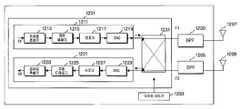
도 12는 본 발명에 따른 투명 중계를 수행하기 위한 중계국의 블록 구성을 도시하고 있다. 이하 설명에서 상기 중계국의 송수신 장치를 구성하는 각 모듈은 상기 도 11에 도시된 기지국의 송수신 장치를 구성하는 각 모듈과 동일한 동작을 수행하므로 설명을 생략한다.12 shows a block configuration of a relay station for performing transparent relay in accordance with the present invention. In the following description, each module constituting the transceiver of the RS performs the same operation as that of each module constituting the transceiver of the BS shown in FIG.
상기 도 12에 도시된 바와 같이 상기 중계국은 두 개의 주파수 대역을 이용할 뿐만 아니라 상기 기지국과 중계국 사이의 중계링크의 채널 용량을 증대시키기 위해 방향성 안테나(1207)와 상기 중계국의 서브셀에 포함되는 단말과의 통신링크를 위한 전방향 안테나(1209)를 구비한다.As shown in FIG. 12, the RS not only uses two frequency bands but also includes a UE included in the
상기 중계국은 RF 스위치(1231)의 동작에 따라, 두 개의 안테나와 두 개의 주파수 대역을 교체하며 동작한다. 즉, 수신장치(1221)는 상기 방향성 안테나(1207)를 이용하여 F1 주파수 대역을 통해 상기 기지국의 하향링크 신호를 수신하면, 송신장치(1201)는 전방향 안테나(1209)를 이용하여 F2 주파수 대역을 통해 상기 서브셀에 포함된 단말들로 상기 기지국의 하향링크 신호를 중계한다. 여기서, 상기 기지국의 하향링크 신호는 이전 타임에 수신된 신호를 의미한다.The relay station operates by swapping two antennas and two frequency bands according to the operation of the
반대로, 상기 수신장치(1221)가 상기 전방향 안테나(1209)를 이용하여 F2 주파수 대역을 통해 상기 단말들의 상향링크 신호를 수신하면, 상기 송신장치(1201)는 방향성 안테나(1207)를 이용하여 F1 주파수 대역을 통해 상기 기지국으로 상기 단말의 상향링크 신호를 중계한다. 여기서, 상기 단말의 상향링크 신호는 이전 타임에 수신된 신호를 의미한다.On the contrary, when the
타이밍 제어기(1233)는 상기 서로 다른 주파수 대역을 이용하여 상기 기지국과 단말로 신호를 송수신하기 위한 타이밍 신호를 발생하여 상기 RF 스위치(1231)의 동작을 제어한다. 또한, 상기 F2 주파수 대역을 동일하게 사용하는 발생하는 역방향 링크의 간섭을 방지하기 위해 상기 기지국의 전송 타이밍과 전송지연을 고려하여 0.5×RTD 만큼 타이밍 전진하여 상기 중계국 하향링크 부프레임을 전송하도록 제어한다.The
한편 본 발명의 상세한 설명에서는 구체적인 실시 예에 관해 설명하였으나, 본 발명의 범위에서 벗어나지 않는 한도 내에서 여러 가지 변형이 가능함은 물론이다. 그러므로 본 발명의 범위는 설명된 실시 예에 국한되어 정해져서는 아니 되며 후술하는 특허청구의 범위뿐만 아니라 이 특허청구의 범위와 균등한 것들에 의해 정해져야 한다.Meanwhile, in the detailed description of the present invention, specific embodiments have been described, but various modifications are possible without departing from the scope of the present invention. Therefore, the scope of the present invention should not be limited to the described embodiments, but should be determined not only by the scope of the following claims, but also by the equivalents of the claims.
상술한 바와 같이, 다중 홉 릴레이 방식의 셀룰러 네트워크에서 다수 개의 주파수 대역을 이용하여 신호를 투명하게 중계함으로써, 기지국의 서비스 영역 확대 및 단말의 호완성(Backward Compatibility)을 가능하게 하고, 기지국과 중계국 링크에 방향성 안테나를 사용함으로써, 상기 중계 링크의 채널 용량을 증대시킬 수 있는 이점이 있다.As described above, by transparently relaying signals using a plurality of frequency bands in a multi-hop relay-based cellular network, it is possible to expand the service area of the base station and backward compatibility of the terminal, and to link the base station and the relay station. By using a directional antenna, there is an advantage that the channel capacity of the relay link can be increased.
Claims (18)
Translated fromKoreanPriority Applications (5)
| Application Number | Priority Date | Filing Date | Title |
|---|---|---|---|
| KR1020060000423AKR100898050B1 (en) | 2006-01-03 | 2006-01-03 | Apparatus and method for transparent relay in a multi-hop relay cellular network |
| US11/649,172US20070155315A1 (en) | 2006-01-03 | 2007-01-03 | Apparatus and method for transparent relaying in a multi-hop relay cellular network |
| EP20070000073EP1804442A1 (en) | 2006-01-03 | 2007-01-03 | Apparatus and method for transparent relaying in a multi-hop relay cellular network |
| CN2007101288425ACN101072065B (en) | 2006-01-03 | 2007-01-04 | Device and method for transparent relay in multi-hop relay cellular network |
| JP2007000189AJP2007184935A (en) | 2006-01-03 | 2007-01-04 | Apparatus and method for transparent relay in multi-hop relay cellular network |
Applications Claiming Priority (1)
| Application Number | Priority Date | Filing Date | Title |
|---|---|---|---|
| KR1020060000423AKR100898050B1 (en) | 2006-01-03 | 2006-01-03 | Apparatus and method for transparent relay in a multi-hop relay cellular network |
Publications (2)
| Publication Number | Publication Date |
|---|---|
| KR20070072984A KR20070072984A (en) | 2007-07-10 |
| KR100898050B1true KR100898050B1 (en) | 2009-05-19 |
Family
ID=38507660
Family Applications (1)
| Application Number | Title | Priority Date | Filing Date |
|---|---|---|---|
| KR1020060000423AExpired - Fee RelatedKR100898050B1 (en) | 2006-01-03 | 2006-01-03 | Apparatus and method for transparent relay in a multi-hop relay cellular network |
Country Status (2)
| Country | Link |
|---|---|
| KR (1) | KR100898050B1 (en) |
| CN (1) | CN101072065B (en) |
Families Citing this family (21)
| Publication number | Priority date | Publication date | Assignee | Title |
|---|---|---|---|---|
| KR100861930B1 (en)* | 2006-03-03 | 2008-10-09 | 삼성전자주식회사 | Apparatus and method for supporting relay service in multi-hop relay broadband wireless access communication system |
| WO2007100232A1 (en) | 2006-03-03 | 2007-09-07 | Samsung Electronics Co., Ltd. | Apparatus and method for supporting relay service in a multi-hop relay broadband wireless access communication system |
| KR100855004B1 (en)* | 2007-03-12 | 2008-08-28 | 삼성탈레스 주식회사 | Communication method using frame structure for transparent relay station in MRM system |
| US8194622B2 (en)* | 2007-12-12 | 2012-06-05 | Motorola Mobility, Inc. | Method and system for managing communication between a base station and subscriber stations |
| CN101483888B (en)* | 2008-01-07 | 2013-06-12 | 上海贝尔股份有限公司 | Data transmission method for wireless access system, base station, relay station and wireless access system |
| CN101527587A (en)* | 2008-03-04 | 2009-09-09 | 大唐移动通信设备有限公司 | Method, system and relay equipment for power control |
| CN101527586B (en)* | 2008-03-04 | 2013-09-18 | 电信科学技术研究院 | Method, system and mobile terminal for path loss compensation |
| CN101527916A (en)* | 2008-03-05 | 2009-09-09 | 中兴通讯股份有限公司 | Method for multiplexing control channel of relay station in orthogonal frequency division multiplexing system |
| KR101481592B1 (en)* | 2008-04-04 | 2015-01-12 | 엘지전자 주식회사 | Transmitting method of signals using the relay station in wireless communication system |
| US8611273B2 (en)* | 2008-07-11 | 2013-12-17 | Interdigital Patent Holdings, Inc. | System level architectures for relayed uplink communication |
| US9294219B2 (en) | 2008-09-30 | 2016-03-22 | Qualcomm Incorporated | Techniques for supporting relay operation in wireless communication systems |
| US9203564B2 (en) | 2008-10-20 | 2015-12-01 | Qualcomm Incorporated | Data transmission via a relay station in a wireless communication system |
| KR101603673B1 (en)* | 2008-12-02 | 2016-03-28 | 삼성전자주식회사 | A method for changing a communication link between source devices and sink devices |
| KR101245505B1 (en) | 2008-12-26 | 2013-03-25 | 후지쯔 가부시끼가이샤 | Radio communication system |
| KR101075964B1 (en)* | 2009-02-02 | 2011-10-21 | 아주대학교산학협력단 | Apparatus and method for relaying multiple links in a communication system |
| WO2010105100A1 (en) | 2009-03-13 | 2010-09-16 | Research In Motion Limited | Relay reception synchronization system and method |
| US8472868B2 (en)* | 2009-05-06 | 2013-06-25 | Telefonaktiebolaget Lm Ericsson (Publ) | Method and apparatus for MIMO repeater chains in a wireless communication network |
| US8599768B2 (en)* | 2009-08-24 | 2013-12-03 | Intel Corporation | Distributing group size indications to mobile stations |
| CN102148784B (en)* | 2010-02-10 | 2013-09-18 | 中国移动通信集团公司 | Communication method, system and device between base station and relay station in relay system |
| CN102238563A (en) | 2010-04-21 | 2011-11-09 | 华为终端有限公司 | Wireless connection method and equipment |
| WO2015161457A1 (en)* | 2014-04-22 | 2015-10-29 | 华为技术有限公司 | Antenna system, relay station and data transmission method |
Citations (7)
| Publication number | Priority date | Publication date | Assignee | Title |
|---|---|---|---|---|
| KR970055837A (en)* | 1995-12-29 | 1997-07-31 | 이우복 | Wireless repeater |
| KR19990004296A (en)* | 1997-06-27 | 1999-01-15 | 박차생 | Frequency conversion mobile telephone repeater and its operation method |
| KR20040027127A (en)* | 2002-09-27 | 2004-04-01 | 주식회사 대우일렉트로닉스 | Method for fabricating tip passivation layer in an atomic force microscope |
| KR20050049456A (en)* | 2005-04-30 | 2005-05-25 | (주)에프알텍 | Common use method of to tdd repeater |
| KR20050101890A (en)* | 2004-04-20 | 2005-10-25 | 알파웨이브(주) | Mobile communications system having different for frequencies between bts and repeater |
| KR20050108240A (en)* | 2004-05-12 | 2005-11-16 | (주)씨앤드에스 마이크로 웨이브 | Cell enhancer, control method thereof, link controller of the cell enhancer, and control method thereof |
| KR20050117995A (en)* | 2004-06-12 | 2005-12-15 | 주식회사 에어텍시스템 | Method for extracting control signal of portable internet wireless transmitter of tdd type |
Family Cites Families (2)
| Publication number | Priority date | Publication date | Assignee | Title |
|---|---|---|---|---|
| FR2708814B1 (en)* | 1993-07-30 | 1995-09-01 | Alcatel Mobile Comm France | Method for covering the shadow areas of a radiocommunication network, and radio repeater for implementing this method. |
| DE60329039D1 (en)* | 2003-12-30 | 2009-10-08 | Nokia Corp | ASYMMETRICAL DATA CONNECTION COMMUNICATION SYSTEM WITH RELAY STATIONS |
- 2006
- 2006-01-03KRKR1020060000423Apatent/KR100898050B1/ennot_activeExpired - Fee Related
- 2007
- 2007-01-04CNCN2007101288425Apatent/CN101072065B/ennot_activeExpired - Fee Related
Patent Citations (7)
| Publication number | Priority date | Publication date | Assignee | Title |
|---|---|---|---|---|
| KR970055837A (en)* | 1995-12-29 | 1997-07-31 | 이우복 | Wireless repeater |
| KR19990004296A (en)* | 1997-06-27 | 1999-01-15 | 박차생 | Frequency conversion mobile telephone repeater and its operation method |
| KR20040027127A (en)* | 2002-09-27 | 2004-04-01 | 주식회사 대우일렉트로닉스 | Method for fabricating tip passivation layer in an atomic force microscope |
| KR20050101890A (en)* | 2004-04-20 | 2005-10-25 | 알파웨이브(주) | Mobile communications system having different for frequencies between bts and repeater |
| KR20050108240A (en)* | 2004-05-12 | 2005-11-16 | (주)씨앤드에스 마이크로 웨이브 | Cell enhancer, control method thereof, link controller of the cell enhancer, and control method thereof |
| KR20050117995A (en)* | 2004-06-12 | 2005-12-15 | 주식회사 에어텍시스템 | Method for extracting control signal of portable internet wireless transmitter of tdd type |
| KR20050049456A (en)* | 2005-04-30 | 2005-05-25 | (주)에프알텍 | Common use method of to tdd repeater |
Also Published As
| Publication number | Publication date |
|---|---|
| KR20070072984A (en) | 2007-07-10 |
| CN101072065B (en) | 2011-03-30 |
| CN101072065A (en) | 2007-11-14 |
Similar Documents
| Publication | Publication Date | Title |
|---|---|---|
| CN101072065B (en) | Device and method for transparent relay in multi-hop relay cellular network | |
| JP2007184935A (en) | Apparatus and method for transparent relay in multi-hop relay cellular network | |
| EP1830490B1 (en) | Apparatus and method for supporting relay service in a multi-hop relay broadband wireless access communication system | |
| EP1890402B1 (en) | Apparatus and method for providing relay service in multi-hop relay broadband wireless access communication system | |
| JP4921492B2 (en) | Apparatus and method for supporting relay service in multi-hop relay broadband wireless access communication system | |
| US8014338B2 (en) | Apparatus and method for supporting relay service in a multi-hop relay broadband wireless access communication system | |
| AU2007239160B2 (en) | Apparatus and method for supporting relay service in a multi-hop relay broadband wireless access communication system | |
| KR20070073138A (en) | Apparatus and method for transparent relay in a multi-hop relay broadband wireless access communication system | |
| EP1783966A2 (en) | Apparatus and method for supporting multiple links by grouping multiple hops | |
| KR20070042224A (en) | Apparatus and method for supporting multiple links in a multi-hop relay cellular network using two frequency bands | |
| KR20070031173A (en) | Apparatus and method for supporting multiple links in a multihop relay cellular network | |
| KR20080047001A (en) | Resource allocating apparatus and method in multi-hop relay broadband wireless access communication system | |
| KR100891144B1 (en) | Apparatus and method for transparent relay in a multi-hop relay cellular network | |
| KR100866024B1 (en) | Apparatus and method for supporting relay service in multi-hop relay broadband wireless access communication system | |
| KR100966521B1 (en) | Apparatus and method for providing relay service in multi-hop relay broadband wireless access communication system |
Legal Events
| Date | Code | Title | Description |
|---|---|---|---|
| PA0109 | Patent application | St.27 status event code:A-0-1-A10-A12-nap-PA0109 | |
| A201 | Request for examination | ||
| P11-X000 | Amendment of application requested | St.27 status event code:A-2-2-P10-P11-nap-X000 | |
| P13-X000 | Application amended | St.27 status event code:A-2-2-P10-P13-nap-X000 | |
| PA0201 | Request for examination | St.27 status event code:A-1-2-D10-D11-exm-PA0201 | |
| PG1501 | Laying open of application | St.27 status event code:A-1-1-Q10-Q12-nap-PG1501 | |
| D13-X000 | Search requested | St.27 status event code:A-1-2-D10-D13-srh-X000 | |
| D14-X000 | Search report completed | St.27 status event code:A-1-2-D10-D14-srh-X000 | |
| E902 | Notification of reason for refusal | ||
| PE0902 | Notice of grounds for rejection | St.27 status event code:A-1-2-D10-D21-exm-PE0902 | |
| E13-X000 | Pre-grant limitation requested | St.27 status event code:A-2-3-E10-E13-lim-X000 | |
| P11-X000 | Amendment of application requested | St.27 status event code:A-2-2-P10-P11-nap-X000 | |
| P13-X000 | Application amended | St.27 status event code:A-2-2-P10-P13-nap-X000 | |
| E701 | Decision to grant or registration of patent right | ||
| PE0701 | Decision of registration | St.27 status event code:A-1-2-D10-D22-exm-PE0701 | |
| GRNT | Written decision to grant | ||
| PR0701 | Registration of establishment | St.27 status event code:A-2-4-F10-F11-exm-PR0701 | |
| PR1002 | Payment of registration fee | St.27 status event code:A-2-2-U10-U11-oth-PR1002 Fee payment year number:1 | |
| PG1601 | Publication of registration | St.27 status event code:A-4-4-Q10-Q13-nap-PG1601 | |
| PR1001 | Payment of annual fee | St.27 status event code:A-4-4-U10-U11-oth-PR1001 Fee payment year number:4 | |
| R18-X000 | Changes to party contact information recorded | St.27 status event code:A-5-5-R10-R18-oth-X000 | |
| FPAY | Annual fee payment | Payment date:20130429 Year of fee payment:5 | |
| PR1001 | Payment of annual fee | St.27 status event code:A-4-4-U10-U11-oth-PR1001 Fee payment year number:5 | |
| FPAY | Annual fee payment | Payment date:20140429 Year of fee payment:6 | |
| PR1001 | Payment of annual fee | St.27 status event code:A-4-4-U10-U11-oth-PR1001 Fee payment year number:6 | |
| FPAY | Annual fee payment | Payment date:20150429 Year of fee payment:7 | |
| PR1001 | Payment of annual fee | St.27 status event code:A-4-4-U10-U11-oth-PR1001 Fee payment year number:7 | |
| FPAY | Annual fee payment | Payment date:20160428 Year of fee payment:8 | |
| PR1001 | Payment of annual fee | St.27 status event code:A-4-4-U10-U11-oth-PR1001 Fee payment year number:8 | |
| FPAY | Annual fee payment | Payment date:20170427 Year of fee payment:9 | |
| PR1001 | Payment of annual fee | St.27 status event code:A-4-4-U10-U11-oth-PR1001 Fee payment year number:9 | |
| LAPS | Lapse due to unpaid annual fee | ||
| PC1903 | Unpaid annual fee | St.27 status event code:A-4-4-U10-U13-oth-PC1903 Not in force date:20180512 Payment event data comment text:Termination Category : DEFAULT_OF_REGISTRATION_FEE | |
| PC1903 | Unpaid annual fee | St.27 status event code:N-4-6-H10-H13-oth-PC1903 Ip right cessation event data comment text:Termination Category : DEFAULT_OF_REGISTRATION_FEE Not in force date:20180512 |