KR100896055B1 - Mobile terminal with rotary input device and display method thereof - Google Patents
Mobile terminal with rotary input device and display method thereofDownload PDFInfo
- Publication number
- KR100896055B1 KR100896055B1KR1020070004212AKR20070004212AKR100896055B1KR 100896055 B1KR100896055 B1KR 100896055B1KR 1020070004212 AKR1020070004212 AKR 1020070004212AKR 20070004212 AKR20070004212 AKR 20070004212AKR 100896055 B1KR100896055 B1KR 100896055B1
- Authority
- KR
- South Korea
- Prior art keywords
- mobile terminal
- wheel
- lens
- jog wheel
- terminal
- Prior art date
- Legal status (The legal status is an assumption and is not a legal conclusion. Google has not performed a legal analysis and makes no representation as to the accuracy of the status listed.)
- Expired - Fee Related
Links
Images


Classifications
- H—ELECTRICITY
- H04—ELECTRIC COMMUNICATION TECHNIQUE
- H04B—TRANSMISSION
- H04B1/00—Details of transmission systems, not covered by a single one of groups H04B3/00 - H04B13/00; Details of transmission systems not characterised by the medium used for transmission
- H04B1/38—Transceivers, i.e. devices in which transmitter and receiver form a structural unit and in which at least one part is used for functions of transmitting and receiving
- G—PHYSICS
- G06—COMPUTING OR CALCULATING; COUNTING
- G06F—ELECTRIC DIGITAL DATA PROCESSING
- G06F1/00—Details not covered by groups G06F3/00 - G06F13/00 and G06F21/00
- G06F1/16—Constructional details or arrangements
- G06F1/1613—Constructional details or arrangements for portable computers
- G06F1/1626—Constructional details or arrangements for portable computers with a single-body enclosure integrating a flat display, e.g. Personal Digital Assistants [PDAs]
- G—PHYSICS
- G03—PHOTOGRAPHY; CINEMATOGRAPHY; ANALOGOUS TECHNIQUES USING WAVES OTHER THAN OPTICAL WAVES; ELECTROGRAPHY; HOLOGRAPHY
- G03B—APPARATUS OR ARRANGEMENTS FOR TAKING PHOTOGRAPHS OR FOR PROJECTING OR VIEWING THEM; APPARATUS OR ARRANGEMENTS EMPLOYING ANALOGOUS TECHNIQUES USING WAVES OTHER THAN OPTICAL WAVES; ACCESSORIES THEREFOR
- G03B11/00—Filters or other obturators specially adapted for photographic purposes
- G03B11/04—Hoods or caps for eliminating unwanted light from lenses, viewfinders or focusing aids
- G03B11/043—Protective lens closures or lens caps built into cameras
- G—PHYSICS
- G06—COMPUTING OR CALCULATING; COUNTING
- G06F—ELECTRIC DIGITAL DATA PROCESSING
- G06F1/00—Details not covered by groups G06F3/00 - G06F13/00 and G06F21/00
- G06F1/16—Constructional details or arrangements
- G06F1/1613—Constructional details or arrangements for portable computers
- G06F1/1633—Constructional details or arrangements of portable computers not specific to the type of enclosures covered by groups G06F1/1615 - G06F1/1626
- G06F1/1684—Constructional details or arrangements related to integrated I/O peripherals not covered by groups G06F1/1635 - G06F1/1675
- G06F1/169—Constructional details or arrangements related to integrated I/O peripherals not covered by groups G06F1/1635 - G06F1/1675 the I/O peripheral being an integrated pointing device, e.g. trackball in the palm rest area, mini-joystick integrated between keyboard keys, touch pads or touch stripes
- G—PHYSICS
- G06—COMPUTING OR CALCULATING; COUNTING
- G06F—ELECTRIC DIGITAL DATA PROCESSING
- G06F3/00—Input arrangements for transferring data to be processed into a form capable of being handled by the computer; Output arrangements for transferring data from processing unit to output unit, e.g. interface arrangements
- G06F3/01—Input arrangements or combined input and output arrangements for interaction between user and computer
- G06F3/03—Arrangements for converting the position or the displacement of a member into a coded form
- G06F3/033—Pointing devices displaced or positioned by the user, e.g. mice, trackballs, pens or joysticks; Accessories therefor
- G06F3/0362—Pointing devices displaced or positioned by the user, e.g. mice, trackballs, pens or joysticks; Accessories therefor with detection of 1D translations or rotations of an operating part of the device, e.g. scroll wheels, sliders, knobs, rollers or belts
- G—PHYSICS
- G06—COMPUTING OR CALCULATING; COUNTING
- G06F—ELECTRIC DIGITAL DATA PROCESSING
- G06F3/00—Input arrangements for transferring data to be processed into a form capable of being handled by the computer; Output arrangements for transferring data from processing unit to output unit, e.g. interface arrangements
- G06F3/01—Input arrangements or combined input and output arrangements for interaction between user and computer
- G06F3/048—Interaction techniques based on graphical user interfaces [GUI]
- G06F3/0481—Interaction techniques based on graphical user interfaces [GUI] based on specific properties of the displayed interaction object or a metaphor-based environment, e.g. interaction with desktop elements like windows or icons, or assisted by a cursor's changing behaviour or appearance
- G06F3/0482—Interaction with lists of selectable items, e.g. menus
- H—ELECTRICITY
- H04—ELECTRIC COMMUNICATION TECHNIQUE
- H04M—TELEPHONIC COMMUNICATION
- H04M1/00—Substation equipment, e.g. for use by subscribers
- H04M1/02—Constructional features of telephone sets
- H04M1/23—Construction or mounting of dials or of equivalent devices; Means for facilitating the use thereof
- H04M1/233—Construction or mounting of dials or of equivalent devices; Means for facilitating the use thereof including a pointing device, e.g. roller key, track ball, rocker switch or joystick
- H—ELECTRICITY
- H04—ELECTRIC COMMUNICATION TECHNIQUE
- H04M—TELEPHONIC COMMUNICATION
- H04M1/00—Substation equipment, e.g. for use by subscribers
- H04M1/72—Mobile telephones; Cordless telephones, i.e. devices for establishing wireless links to base stations without route selection
- H04M1/724—User interfaces specially adapted for cordless or mobile telephones
- H04M1/72469—User interfaces specially adapted for cordless or mobile telephones for operating the device by selecting functions from two or more displayed items, e.g. menus or icons
Landscapes
- Engineering & Computer Science (AREA)
- Theoretical Computer Science (AREA)
- General Engineering & Computer Science (AREA)
- Physics & Mathematics (AREA)
- General Physics & Mathematics (AREA)
- Human Computer Interaction (AREA)
- Computer Hardware Design (AREA)
- Signal Processing (AREA)
- Computer Networks & Wireless Communication (AREA)
- Studio Devices (AREA)
- Telephone Set Structure (AREA)
- Fittings On The Vehicle Exterior For Carrying Loads, And Devices For Holding Or Mounting Articles (AREA)
Abstract
Translated fromKoreanDescription
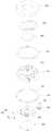
Translated fromKorean도1은 본 발명에 따른 일실시예의 개략적 단면도.1 is a schematic cross-sectional view of one embodiment according to the present invention.
도2는 본 발명의 일실시예의 주요부의 분해 사시도.Figure 2 is an exploded perspective view of the main part of an embodiment of the present invention.
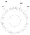
도3은 본 발명에 따른 일실시예의 배면도.Figure 3 is a rear view of one embodiment according to the present invention.
도4는 본 발명에 따른 일실시예의 조그휠의 배면도.Figure 4 is a rear view of the jog wheel of one embodiment according to the present invention.
도5는 본 발명에 따른 일실시예의 조그휠의 배면 사시도.Figure 5 is a rear perspective view of the jog wheel of one embodiment according to the present invention.
도6은 본 발명에 따른 일실시예에서 제1탄성부재가 장착된 조그휠의 배면 사시도.Figure 6 is a rear perspective view of the jog wheel mounted with the first elastic member in one embodiment according to the present invention.
도7은 본 발명에 따른 일실시예의 렌즈개폐수단의 사시도.Figure 7 is a perspective view of the lens opening and closing means of one embodiment according to the present invention.
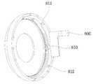
도8은 본 발명에 따른 일실시예의 렌즈개폐수단의 배면 사시도.Figure 8 is a rear perspective view of the lens opening and closing means of one embodiment according to the present invention.
도9는 본 발명에 따른 일실시예의 프레임의 사시도.Figure 9 is a perspective view of the frame of one embodiment according to the present invention.
도10은 본 발명에 따른 일실시예에서 조그휠과 홀센서의 조립 상태도.Figure 10 is an assembly state of the jog wheel and the hall sensor in one embodiment according to the present invention.
도11, 도12, 도13, 도14, 도15 및 도16은 본 발명에 따른 일실시예의 작동도.11, 12, 13, 14, 15 and 16 are operational views of one embodiment according to the present invention.
<도면의 주요부분에 대한 부호의 설명><Description of the symbols for the main parts of the drawings>
100:표시부200:조그휠100: display part 200: jog wheel
210:지지돌기220:저지돌기210: support protrusion 220: low protrusion
230:체결돌기240:토션스프링230: fastening protrusion 240: torsion spring
300:렌즈개폐수단310:고정판300: lens opening and closing means 310: fixed plate
312:걸림홈314:안내돌기312: locking groove 314: guide projection
320:회전판322:회전돌기320: rotating plate 322: rotating projection
330:렌즈커버332:힌지축330: lens cover 332: hinge axis
340:코일스프링400:프레임340: coil spring 400: frame
410:프레임 몸체412:걸림턱410: frame body 412: locking jaw
420:지지돌기422:안착턱420: support protrusion 422: seating jaw
424:걸림돌기430:이동돌기424: locking projection 430: moving projection
460:이물질 침투 방지창470:드러스트 와셔(thrust washer)460: foreign matter penetration prevention window 470: thrust washer
472:고정홈480:고정와셔472: fixed groove 480: fixed washer
482:체결홈500:카메라482: fastening groove 500: camera
600:지지판610:압박돌기600: support plate 610: pressing protrusion
700:모우터720:상하이동돌기700: motor 720: up and down moving protrusions
800:연성회로기판810:홀센서800: flexible circuit board 810: Hall sensor
812:마그네틱900:인쇄회로기판812: magnetic 900: printed circuit board
912:고정 신호단자920:돔스위치912: fixed signal terminal 920: dome switch
922:가변 신호단자922: variable signal terminal
본 발명은 단말기 작동을 위한 회전입력장치가 구비된 이동단말기 및 그 디스플레이 방법에 관한 것이다.The present invention relates to a mobile terminal equipped with a rotation input device for operating a terminal and a display method thereof.
종래 회전입력장치가 구비된 이동단말기의 경우 회전입력장치가 단말기의 전면에 구비되거나 단말기의 측면에 구비되어 단말기 사용시 한 손으로 회전입력장치를 작동하기에 불편한 점이 있었다.In the case of a mobile terminal equipped with a conventional rotation input device, the rotation input device is provided on the front side of the terminal or is provided on the side of the terminal, which makes it inconvenient to operate the rotation input device with one hand when using the terminal.
본 발명은 단말기 사용시 한 손으로 작동이 용이한 회전입력장치를 구비한 이동단말기 및 그 디스플레이 방법을 제공하고자 한다.The present invention is to provide a mobile terminal having a rotary input device that is easy to operate with one hand when using the terminal and a display method thereof.
본 발명은 표시부에 디스플레이되는 영상을 보면서 한 손으로 용이하게 작동시킬 수 있는 회전입력장치를 구비한 이동단말기 및 그 디스플레이 방법을 제공하고자 한다.The present invention is to provide a mobile terminal having a rotation input device that can be easily operated with one hand while watching the image displayed on the display unit and a display method thereof.
본 발명은 그 기능이 다양한 회전입력장치를 갖는 이동단말기 및 그 디스플레이 방법을 제공하고자 한다.An object of the present invention is to provide a mobile terminal having a variety of rotation input devices and a display method thereof.
본 발명은 단말기의 전방에 노출 가능한 표시부와, 상기 단말기의 배면에 위치하는 회전입력장치를 포함하는 것을 특징으로 하는 회전입력장치 구비 이동단말기 및 그 디스플레이 방법에 관한 것이다.The present invention relates to a mobile terminal with a rotation input device and a display method thereof, comprising a display unit which can be exposed in front of the terminal, and a rotation input device positioned on the rear of the terminal.
본 발명은 상기 회전입력장치의 양방향 회전시 상기 회전입력장치가 최초의 설정위치로 복귀되도록 탄성력을 제공하는 제1탄성부재와, 상기 회전입력장치의 회 전방향을 인식하는 감지센서를 포함하기도 한다.The present invention may include a first elastic member for providing an elastic force so that the rotation input device returns to the initial setting position when the rotation input device is bidirectionally rotated, and a sensing sensor for recognizing the rotation direction of the rotation input device. .
본 발명에 있어서, 상기 회전입력장치는, 상면이 상기 단말기의 배면에 노출되는 조그휠이고, 상기 단말기 내부에는 상기 조그휠이 양방향으로 회전 가능하도록 안착되는 프레임이 구비되기도 한다.In the present invention, the rotation input device, the top surface is a jog wheel exposed on the back of the terminal, the inside of the terminal may be provided with a frame seated so that the jog wheel can be rotated in both directions.
본 발명에 있어서, 상기 제1탄성부재는 양측 돌출단부를 갖는 토션스프링이고, 상기 조그휠 또는 프레임 중 어느 하나에는 상기 토션스프링의 양측 돌출단부를 압축 가능한 상태로 지지시키기 위한 지지돌기가 돌출 형성되고, 상기 조그휠 또는 프레임 중 나머지 하나에는 상기 조그휠의 양방향 회전에 따라 상기 토션스프링의 양측 돌출단부를 선택적으로 가압하여 이동시키기 위한 이동돌기가 형성되기도 한다.In the present invention, the first elastic member is a torsion spring having both protruding ends, and one of the jog wheel or the frame is provided with a support projection for supporting both protruding ends of the torsion spring in a compressible state. In addition, the jog wheel or the other one of the frames may be provided with moving projections for selectively pressing and moving both protruding ends of the torsion spring according to the bidirectional rotation of the jog wheel.
본 발명에 있어서, 상기 지지돌기는 상기 조그휠에 돌출 형성되고, 상기 이동돌기는 상기 프레임에 돌출 형성되며, 상기 조그휠에는 상기 조그휠의 양방향 회전시 상기 조그휠의 회전각도를 제한하기 위한 저지돌기가 돌출 형성되기도 한다.In the present invention, the support protrusion protrudes to the jog wheel, the moving protrusion protrudes to the frame, the jog wheel is a jersey for limiting the rotation angle of the jog wheel when bidirectional rotation of the jog wheel Protuberances may also protrude.
본 발명에 있어서, 상기 이동돌기는 상기 조그휠의 최초의 설정위치에서 상기 토션스프링의 양측 돌출단부와 각각 접촉하도록 상기 프레임에 2개 돌출 형성되기도 한다.In the present invention, two moving projections may be formed on the frame so as to contact each protruding end of both sides of the torsion spring at the initial setting position of the jog wheel.
본 발명에 있어서, 상기 저지돌기는 상기 토션스프링의 둘레부에 접촉부와 접촉하고, 상기 조그휠의 양방향 회전시 양측 단부가 상기 이동돌기 중 어느 하나와 선택적으로 접촉하도록 상기 조그휠에 원호형으로 형성되는 것을 특징으로 하는 회전입력장치 구비 이동단말기.In the present invention, the blocking projection is in contact with the contact portion on the circumference of the torsion spring, and formed in an arc shape on the jog wheel such that both ends of the jog wheel selectively contact with any one of the moving projection during bidirectional rotation of the jog wheel. Mobile terminal with a rotation input device, characterized in that the.
본 발명에 있어서, 상기 조그휠의 하단부에는 상면 내측이 상기 프레임에 형성되는 걸림턱에 걸려 상기 조그휠의 상측 이탈을 저지하는 고정와셔가 체결되기도 한다.In the present invention, a fixing washer may be fastened to a lower end of the jog wheel to prevent an upper side of the jog wheel from being caught by a locking jaw formed on the inner surface of the top surface.
본 발명에 있어서, 상기 감지센서는 상기 조그휠이 회전함에 따라 상기 조그휠에 구비된 마그네틱에 의한 자기장의 변화를 감지하는 홀센서이기도 하다.In the present invention, the detection sensor is also a Hall sensor for detecting a change in the magnetic field due to the magnetic provided in the jog wheel as the jog wheel rotates.
본 발명은 상기 단말기의 배면에 위치하는 카메라를 포함하기도 한다.The present invention also includes a camera located on the back of the terminal.
본 발명에 있어서, 상기 조그휠의 내측에는 카메라가 구비되고, 상기 조그휠에는 상기 카메라의 렌즈가 외부로 노출되도록 통공이 형성되기도 한다.In the present invention, a camera is provided on the inside of the jog wheel, and the through hole may be formed on the jog wheel so that the lens of the camera is exposed to the outside.
본 발명은 상기 카메라의 렌즈를 개폐하는 렌즈개폐수단이 구비되기도 한다.The present invention may be provided with a lens opening and closing means for opening and closing the lens of the camera.
본 발명에 있어서, 상기 렌즈개폐수단은, 상기 렌즈가 외부로 노출되도록 통공이 형성되는 고정판과, 상기 고정판의 하측에 위치하고, 상기 렌즈가 외부로 노출되도록 통공이 형성되며, 일측 방향으로 회전 가능한 회전판과, 상기 고정판의 상측에 위치하며, 상기 회전판에 연결되어 상기 회전판이 회전함에 따라 상기 고정판에 형성된 통공을 개폐하는 렌즈커버를 포함하기도 한다.In the present invention, the lens opening and closing means, the fixing plate is formed with a through-hole so that the lens is exposed to the outside, the lower side of the fixing plate, the through-hole is formed so that the lens is exposed to the outside, the rotating plate rotatable in one direction And, it is located on the upper side of the fixing plate, it may include a lens cover connected to the rotating plate to open and close the through hole formed in the fixed plate as the rotating plate rotates.
본 발명은 상기 고정판과 회전판 사이에 구비되어 상기 회전판의 회전시 상기 회전판이 최초의 설정위치로 복귀되도록 탄성력을 제공하는 제2탄성부재를 포함하기도 한다.The present invention may include a second elastic member provided between the fixed plate and the rotating plate to provide an elastic force so that the rotating plate returns to the initial setting position when the rotating plate rotates.
본 발명에 있어서, 상기 제2탄성부재는 일측 단부가 상기 고정판에 연결되고, 타측 단부가 상기 회전판에 연결되는 코일스프링이기도 하다.In the present invention, the second elastic member is also a coil spring whose one end is connected to the fixed plate, the other end is connected to the rotating plate.
본 발명에 있어서, 상기 렌즈커버는, 상기 회전판이 회전함에 따라 상기 고 정판의 한 점을 축으로 회전하는 제1커버와, 상기 회전판이 회전함에 따라 상기 고정판의 다른 한 점을 축으로 회전하며 상기 제1커버와 접촉 및 이격되는 제2커버를 포함하기도 한다.In the present invention, the lens cover, the first cover for rotating one point of the fixed plate in the axis as the rotating plate rotates, and the other point of the fixed plate rotates in the axis as the rotating plate rotates the It may also include a second cover in contact with and spaced apart from the first cover.
본 발명에 있어서, 상기 회전판의 하측에는 상하 이동 가능한 상하이동돌기가 구비되고, 상기 회전판의 하면에는 상기 상하이동돌기의 상측 이동시 상기 상하이동돌기와 접촉하는 경사면이 형성되어 상기 회전판을 회전시키는 회전돌기가 돌출 형성되기도 한다.In the present invention, the lower side of the rotating plate is provided with a shangdong copper protrusion that can be moved up and down, the lower surface of the rotating plate is formed with an inclined surface in contact with the shanghai copper protrusion when the upper side of the shandong copper projection is rotated to rotate the rotating plate It may also protrude.
본 발명에 있어서, 상기 상하이동돌기는 모우터 회전에 의해 상하 이동하는 리드 스크류에 연결되기도 한다.In the present invention, the shandong copper projection may be connected to the lead screw that moves up and down by the rotation of the motor.
본 발명에 있어서, 상기 프레임의 하측에는 특정 모드 선택을 위한 하나 이상의 신호단자가 구비되고, 상기 신호단자의 상측에는 상기 조그휠의 가압시 하부로 이동하여 상기 신호단자를 작동시키는 압박돌기가 구비되기도 한다.In the present invention, the lower side of the frame is provided with at least one signal terminal for selecting a specific mode, the upper side of the signal terminal is provided with a pressing projection for moving the signal terminal to move to the lower side when pressing the jog wheel. do.
본 발명에 있어서, 상기 프레임의 하측부에는 상기 프레임을 지지하는 지지판이 구비되고, 상기 압박돌기는 상기 지지판의 하면에 돌출 형성되기도 한다.In the present invention, the lower side of the frame is provided with a support plate for supporting the frame, the pressing projection may be formed protruded on the lower surface of the support plate.
한편, 본 발명은 단말기의 전방에 노출 가능한 표시부와, 상기 단말기의 배면에 위치하는 회전입력장치를 포함하며, 상기 표시부에는 특정 모드 선택을 위한 적어도 하나의 아이콘이 디스플레이되는 것을 특징으로 하는 회전입력장치 구비 이동단말기에 관한 것이다.On the other hand, the present invention includes a display unit that can be exposed to the front of the terminal, and a rotation input device located on the back of the terminal, wherein the display unit at least one icon for selecting a particular mode is displayed The present invention relates to an equipped mobile terminal.
본 발명에 있어서, 상기 표시부에는 상기 적어도 하나의 아이콘 중 어느 하나를 지시하기 위한 인디케이터(indicator)가 디스플레이되기도 한다.In the present invention, an indicator for indicating one of the at least one icon may be displayed on the display unit.
본 발명에 있어서, 상기 인디케이터(indicator)는 상기 회전입력장치의 회전에 따라 상기 적어도 하나의 아이콘 간을 이동하기도 한다.In the present invention, the indicator may move between the at least one icon according to the rotation of the rotation input device.
한편, 본 발명은 단말기의 전방에 노출 가능한 표시부와, 상기 단말기의 배면에 위치하는 회전입력장치를 포함하며, 상기 회전입력장치의 회전에 따라 카메라 모드에서의 줌(zoom) 기능, 상기 단말기에 저장된 동영상 또는 정지영상의 줌(zoom) 기능, 볼륨 업(volume up) 및 볼륨 다운(volume down) 기능, 상기 단말기에 저장된 동영상 또는 정지영상의 좌우 스크롤(scrole) 기능 중 적어도 어느 하나의 특정 기능이 실행되는 것을 특징으로 하는 회전입력장치 구비 이동단말기에 관한 것이다.On the other hand, the present invention includes a display unit that can be exposed in front of the terminal, and a rotation input device located on the back of the terminal, the zoom function in the camera mode according to the rotation of the rotation input device, stored in the terminal At least one of a zoom function of a moving picture or still image, a volume up and volume down function, and a left and right scroll function of a moving picture or a still image stored in the terminal are executed. It relates to a mobile terminal with a rotation input device characterized in that the.
본 발명은, 상기 회전입력장치가 회전한 상태에서 소정 시간 경과할 때마다 상기 특정 기능 중 적어도 어느 하나가 정해진 정도에 따라 연속적으로 실행되기도 한다.According to the present invention, at least one of the specific functions may be continuously executed whenever a predetermined time elapses while the rotation input device is rotated.
본 발명에 있어서, 상기 표시부에는, 상기 특정 기능 중 적어도 어느 하나의 실행 정도를 알려주기 위한 인디케이터(indicator)가 디스플레이되기도 한다.In the present invention, an indicator for informing the execution degree of at least one of the specific functions may be displayed on the display unit.
한편, 본 발명은 단말기의 전방에 노출 가능하며 터치스크린을 포함하는 표시부와, 상기 단말기의 배면에 위치하는 회전입력장치를 포함하는 것을 특징으로 하는 회전입력장치 구비 이동단말기에 관한 것이다.On the other hand, the present invention relates to a mobile terminal having a rotation input device, characterized in that it comprises a display unit which can be exposed to the front of the terminal and includes a touch screen, and a rotation input device located on the back of the terminal.
본 발명에 있어서, 상기 터치스크린은 특정 모드 선택을 위한 소정의 터치영역을 포함하기도 한다.In the present invention, the touch screen may also include a predetermined touch area for selecting a specific mode.
본 발명에 있어서, 상기 터치스크린에는 특정 모드 선택을 위한 적어도 하나 의 아이콘 및 상기 아이콘 중 어느 하나를 지시하기 위한 인디케이터(indicator)가 디스플레이되되, 상기 인디케이터(indicator)에 의해 지시되는 아이콘은 상기 소정의 터치영역에 디스플레이되기도 한다.In the present invention, the touch screen displays at least one icon for selecting a particular mode and an indicator for indicating any one of the icons, the icon indicated by the indicator is the predetermined It may be displayed on the touch area.
본 발명에 있어서, 상기 소정의 터치영역은 상기 터치스크린의 중앙부에 형성되고, 상기 특정 모드 선택을 위한 아이콘은 상기 소정의 터치영역을 중심으로 원주형태를 이루며 디스플레이되기도 한다.In the present invention, the predetermined touch area is formed in the center of the touch screen, and the icon for selecting a particular mode may be displayed in a circumferential shape around the predetermined touch area.
본 발명에 있어서, 상기 인디케이터(indicator)는, 상기 인디케이터(indicator)에 의해 지시되는 아이콘이 디스플레이되었던 위치에 당해 아이콘을 대체하며 디스플레이되기도 한다.In the present invention, the indicator may be displayed while replacing the icon at the position where the icon indicated by the indicator was displayed.
이하, 도면을 참조하여 본 발명의 일실시예에 대해 상세히 설명한다. 도1은 본 발명에 따른 일실시예의 개략적 단면도를, 도2는 본 발명의 일실시예의 주요부의 분해 사시도를, 도3은 본 발명에 따른 일실시예의 배면도를, 도4는 본 발명에 따른 일실시예의 조그휠의 배면도를, 도5는 본 발명에 따른 일실시예의 조그휠의 배면 사시도를, 도6은 본 발명에 따른 일실시예에서 제1탄성부재가 장착된 조그휠의 배면 사시도를, 도7은 본 발명에 따른 일실시예의 렌즈개폐수단의 사시도를, 도8은 본 발명에 따른 일실시예의 렌즈개폐수단의 배면 사시도를, 도9는 본 발명에 따른 일실시예의 프레임의 사시도를, 도10은 본 발명에 따른 일실시예에서 조그휠과 홀센서의 조립 상태도를, 도11, 도12, 도13, 도14, 도15 및 도16은 본 발명에 따른 일실시예의 작동도를 나타낸다.Hereinafter, an embodiment of the present invention will be described in detail with reference to the drawings. Figure 1 is a schematic cross-sectional view of one embodiment according to the present invention, Figure 2 is an exploded perspective view of the main part of an embodiment of the present invention, Figure 3 is a rear view of an embodiment according to the present invention, Figure 4 according to the present invention 5 is a rear perspective view of the jog wheel according to the present invention, and FIG. 6 is a rear perspective view of the jog wheel mounted with the first elastic member in one embodiment according to the present invention. 7 is a perspective view of a lens opening and closing means of one embodiment according to the present invention, FIG. 8 is a rear perspective view of a lens opening and closing means according to an embodiment of the present invention, and FIG. 9 is a perspective view of a frame of an embodiment according to the present invention. 10 is an assembly state diagram of a jog wheel and a hall sensor in one embodiment according to the present invention, FIGS. 11, 12, 13, 14, 15 and 16 are operation diagrams of an embodiment according to the present invention. Indicates.
도1 및 도2를 참조하면 본 발명에 따른 일실시예는 표시부(100), 조그휠(200), 렌즈개폐수단(300), 프레임(400), 카메라(500) 및 지지판(600)을 갖는다.1 and 2, an embodiment according to the present invention includes a
도1을 참조하면 본 발명에 따른 일실시예에 있어서 표시부(100)는 단말기의 전면에 구비된다.Referring to FIG. 1, in an embodiment of the present invention, the
도1을 참조하면 조그휠(200)은 상면이 외부에 노출되도록 단말기의 배면에 구비된다.Referring to Figure 1, the
도2를 참조하면 조그휠(200)은 상면과, 상기 상면으로부터 하부로 연장되는 경사부와, 상기 경사부로부터 하부로 연장되는 둘레부를 갖는다. 도2를 참조하면 조그휠(200)의 상면에는 카메라(500)의 렌즈가 외부로 노출되도록 통공이 형성된다. 도3을 참조하면 조그휠(200)의 상면에는 단말기의 모드(mode) 선택을 위한 폰트(font)가 형성된다.2, the
도4 및 도5를 참조하면 조그휠(200)의 배면에는 지지돌기(210)가 돌출 형성된다. 지지돌기(210)는 원호형으로 형성되는데, 외측면이 조그휠(200)의 둘레부의 내면과 일체가 되도록 형성된다.4 and 5, the
도4 및 도5를 참조하면 조그휠(200)의 배면에는 저지돌기(220)가 돌출 형성된다. 저지돌기(220)는 원호형으로 형성되는데, 외측면이 지지돌기(210)의 내면과 일체가 되도록 형성된다. 저지돌기(220)는, 조그휠(200)의 중앙을 중심하였을 때 저지돌기(220)의 양측단이 지지돌기(210)의 양측단과 이루는 각이 각각 시계 및 반시계 방향으로 45°보다 약간 큰 각을 이루도록 형성된다. 또한 저지돌기(220)는 그 돌출 높이가 지지돌기(210)의 돌출 높이보다 낮도록 형성된다.4 and 5, the stopping
도4 및 도5를 참조하면 조그휠(200)의 둘레부의 하단부에는 하나 이상의 체결돌기(230)가 돌출 형성된다.4 and 5, one or
도6을 참조하면 조그휠(200)의 배면에는 토션스프링(240)이 장착된다. 토션스프링(240)은 양측 말단에 원주방향에 수직한 방향으로 돌출되는 돌출단부를 갖는다. 토션스프링(240)은 양측 돌출단부가 지지돌기(210)의 양측단에 접촉함으로써 고정된다. 한편, 토션스프링(240)은 그 감김부의 소정부위가 저지돌기(220)의 내면에 접촉하도록 장착된다.Referring to FIG. 6, a
도1을 참조하면 프레임(400)에는 조그휠(200)이 회전 가능하도록 안착된다.Referring to FIG. 1, the
도9를 참조하면 프레임(400)은 프레임 몸체(410)를 갖는다. 프레임 몸체(410)의 중앙부에는 상하를 관통하는 통공이 형성되며, 프레임 몸체(410)의 상단 근부로부터 상단에 이르기까지는 외벽이 외부로 돌출되며 걸림턱(412)이 형성된다. 돌출된 프레임 몸체(410)의 상단 외벽은 원주형태를 이루는데, 조그휠(200)이 프레임(400)에 안착되는 경우 조그휠(200) 둘레부의 내면과 접촉하지 않도록, 그 지름은 조그휠(200) 둘레부의 내면의 지름보다 약간 작게 형성된다. 한편, 도9 및 도6을 참조하면 돌출된 프레임 몸체(410)의 상단 외벽의 높이는 조그휠(200)의 둘레부의 하단과 지지돌기(210)의 하단과의 높이 차이에 해당한다.Referring to FIG. 9, the
도9를 참조하면 프레임 몸체(410)의 상면에는 지지돌기(420)가 돌출 형성된다. 지지돌기(420)는 원호형으로 형성되는데, 프레임 몸체(410)의 상면 가장자리로부터 내부로 소정 거리 인입되어 돌출 형성된다. 지지돌기(420)는, 조그휠(200)이 프레임(400)에 안착되는 경우 토션스프링(240)의 감김부 안쪽에 위치하도록, 그 외 면 지름을 토션스프링(240)의 감김부의 지름보다 작게 형성한다.9, the
도9를 참조하면 지지돌기(420)의 내면에는, 원판이 안착될 수 있도록 원주방향을 따라 안착턱(422)이 형성된다. 한편, 안착턱(422)의 소정부위에는 상측으로 걸림돌기(424)가 돌출 형성된다.9, a mounting
도9를 참조하면 프레임 몸체(410)의 상면에는 이동돌기(430)가 2개 돌출 형성되는데, 각각 지지돌기(420)의 외측에 형성된다. 도6을 참조하면 각각의 이동돌기(430)는, 조그휠(200)이 프레임(400)에 안착시 토션스프링(240)의 양측 돌출단부에 각각 접촉하여 조그휠(200)이 양방향으로 회전하는 경우 토션스프링(240)을 압축할 수 있도록 형성된다. 또한, 이동돌기(430)는 조그휠(200)이 양방향으로 회전하는 경우 각각 조그휠(200)의 저지돌기(220)의 양측단의 어느 하나와 선택적으로 접촉하여 조그휠(200)의 회전을 저지하는 위치에 형성된다. 또한, 이동돌기(430)의 원주방향 길이는, 조그휠(200)이 양방향으로 45° 만큼 회전하는 경우 이동돌기(430)가 각각 조그휠(200)의 저지돌기(220)의 양측단의 어느 하나와 선택적으로 접촉하도록 형성된다. 따라서, 이동돌기(430) 각각은 조그휠(200)이 프레임(400)에 안착되는 경우 토션스프링(240)의 감김부의 외측에 위치하도록 형성된다.Referring to FIG. 9, two moving
도1 및 도2를 참조하면 프레임(400)의 내측에는 카메라(500)가 설치되는데, 카메라(500)의 전방부가 프레임(400) 중앙부에 형성된 통공에 삽입된다.1 and 2, a
도2를 참조하면 프레임(400)의 중앙부에 형성된 통공에는 투명재질의 이물질 침투 방지창(460)이 구비된다. 이물질 침투 방지창(460)은 외부로부터 카메라(500)의 렌즈에 이물질이 침투되는 것을 방지하기 위한 것이다.Referring to FIG. 2, the through hole formed in the center of the
도2 및 도4를 참조하면 프레임 몸체(410) 상면에는 드러스트 와셔(thrust washer)(470)가 장착된다. 드러스트 와셔(thrust washer)(470)는 지지돌기(420)의 외측에 위치하는데, 2개의 이동돌기(430)에 삽입 고정되도록 2개의 고정홈(472)이 형성된다. 드러스트 와셔(thrust washer)(470)는 조그휠(200)이 프레임(400)에 안착되는 경우 조그휠(200)의 저지돌기(220)를 지지하도록 장착되며, 드러스트 와셔(thrust washer)(470)의 두께는 조그휠(200)의 지지돌기(210)와 저지돌기(220)의 높이 차이에 해당한다. 드러스트 와셔(thrust washer)(470)는 조그휠(200)과 프레임(400)의 회전시 마찰을 감소시키고, 회전을 부드럽게 하기 위한 것이다.2 and 4, a
도2를 참조하면 조그휠(200)이 프레임(400)에 안착하는 경우 조그휠(200)의 둘레부 하단면에는 고정와셔(480)가 체결된다. 따라서, 고정와셔(480)에는 조그휠(200)의 둘레부 하단면에 돌출 형성된 체결돌기(230)에 대응하는 체결홈(482)이 형성된다. 고정와셔(480)의 상면 외측부는 조그휠(200)의 둘레부 하단면과 접촉하고, 고정와셔(480)의 상면 내측부는 프레임 몸체(410)의 걸림턱(412)과 접촉한다. 즉, 고정와셔(480)과 조그휠(200)의 둘레부 하단면에 체결되어 프레임 몸체(410)의 걸림턱(412)에 걸림으로써 조그휠(200)이 프레임(400)으로부터 이탈되는 것이 방지된다.Referring to FIG. 2, when the
도7 및 도8을 참조하면 카메라(500)의 렌즈를 개폐하는 렌즈개폐수단(300)은 프레임(400)에 장착되는데, 고정판(310), 회전판(320) 및 렌즈커버(330)를 갖는다.7 and 8, the lens opening and closing means 300 for opening and closing the lens of the
도7 및 도8을 참조하면 고정판(310)의 외곽은 2개의 원호부와 상기 2개의 원호부를 연결하는 2개의 직선부로 형성되는데, 하나의 원호부는 나머지 하나의 원호 부와 마주보고 하나의 직선부는 나머지 하나의 직선부와 마주보도록 형성된다. 한편, 2개의 원호부는 프레임(400)의 안착턱(422)에 안착되도록 형성되며, 원호부 각각에는 고정판(310)의 회전을 방지하기 위하여 프레임(400)의 걸림돌기(424)에 걸리는 걸림홈(312)이 형성된다. 또한, 고정판(310)의 중앙부에는 고정판(310)의 하측, 즉 고정판(310)의 배면방향에 위치하는 카메라(500)의 렌즈가 외부에 노출되도록 통공이 형성된다.Referring to FIGS. 7 and 8, the outer side of the fixing
도8을 참조하면 고정판(310)의 하측에는 회전판(320)이 구비된다. 회전판(320)의 중앙부에는 회전판(320)의 하측에 위치하는 카메라(500)의 렌즈가 외부에 노출되도록 통공이 형성된다. 즉, 회전판(320)은 환테고리형으로 형성된다. 회전판(320)의 외주면에는 요입홈이 형성되며, 상기 요입홈에는 코일스프링(340)이 장착된다. 코일스프링(340)은 일측단이 고정판(310)에 연결되고, 타측단이 회전판(320)에 연결된다. 한편, 회전판(320)의 하면에는 회전돌기(322)가 돌출 형성된다. 회전돌기(322)에는, 상하방향 운동을 수평방향 운동으로 바꾸기 위하여 상하방향으로 경사진 경사면이 형성된다.Referring to FIG. 8, the rotating plate 320 is provided below the fixing
도7을 참조하면 고정판(310)의 상측에는 렌즈커버(330)가 구비된다. 렌즈커버(330)는 제1렌즈커버 및 제2렌즈커버로 이루어지는데, 렌즈커버(330) 각각은 소정부위가 고정판(310) 상면에 힌지축(332)을 중심으로 회동함으로써 상호 접촉 및 이격됨으로써 고정판(310)에 형성된 통공을 개폐하도록 형성된다. 또한, 렌즈커버(330) 각각은 일측단이 회전판(320)에 고정 연결되어, 회전판(320)이 일측 방향으로 회전함에 따라 힌지축(332)을 중심으로 회전하여 고정판(310)에 형성된 통공 을 개방하도록 형성된다. 도7을 참조하면 고정판(310)의 상면에는 렌즈커버(330) 회전시 렌즈커버(330)를 안내하기 위한 안내돌기(314)가 돌출 형성된다.Referring to FIG. 7, a
한편, 도7 및 도8을 참조하면 코일스프링(340)은 회전판(320)이 회전하여 렌즈커버(330)가 개방되는 경우 회전판(320) 및 렌즈커버(330)를 최초의 위치로 복귀시키기 위한 탄성복원력을 제공하도록 장착된다.Meanwhile, referring to FIGS. 7 and 8, the coil spring 340 may be configured to return the rotating plate 320 and the
도2를 참조하면 카메라(500)의 측부에는 모우터(700)가 구비된다. 모우터(700)에는 모우터(700) 회전시 상하 이동 가능한 리드(lead) 스크류(screw)가 구비되고, 리드(lead) 스크류(screw)에는 상하이동돌기(720)가 연결된다. 상하이동돌기(720)에는 리드(lead) 스크류(screw)가 상하 이동함에 따라 회전돌기(322)의 경사면과 미끄럼 접촉하는 경사면이 형성된다. 즉, 상하이동돌기(720)가 모우터(700)의 회전시 상부로 이동함에 따라 회전돌기(322)와 접촉하며 회전돌기(322)에 회전력을 가하여 회전판(320)을 회전시키게 되는 것이다.Referring to FIG. 2, a
도2를 참조하면 카메라(500)에는 연성회로기판(800)이 연결된다. 연성회로기판(800)에는 홀센서(810)가 실장되며, 홀센서(810) 작동을 위한 신호단자 및 모우터(700) 작동을 위한 신호단자 등이 패턴화된다. 도10을 참조하면 조그휠(200)의 둘레부 내면에는 2개의 마그네틱(812)이 장착되는데, 하나는 N극이고 나머지 하나는 S극을 띠는 마그네틱이다. 즉, 홀센서(810)는 조그휠(200)이 회전함에 따라 조그휠(200)에 장착된 마그네틱(812)에 의한 자기장의 변화를 감지함으로써 조그휠(200)의 회전방향을 감지하기 위한 것이다. 한편, 연성회로기판(800)은 최초 설정상태에서 홀센서(810)가 2개의 마그네틱(812) 중앙부에 위치하도록 장착된다.2, a
도1 및 도2를 참조하면 카메라(500)의 하단부는 카메라(500)를 지지하는 원판형의 지지판(600)이 구비된다. 지지판(600)의 하측에는 등간격으로 원주형태를 이루며 압박돌기(610)가 돌출 형성된다.1 and 2, the lower end of the
도1을 참조하면 단말기에는 인쇄회로기판(900)이 구비된다. 인쇄회로기판(900)에는 고정 신호단자(912)가 형성된다. 고정 신호단자(912)는 압박돌기(610)에 대응하도록 등간격으로 원주형태를 이루며 형성된다. 또한 인쇄회로기판(900)에는 연성인쇄회로기판(800)이 회로적으로 연결된다.Referring to FIG. 1, a terminal is provided with a printed
도1을 참조하면 고정 신호단자(912)의 상측에는 돔스위치(920)가 실장된다. 돔스위치(920)는 각각의 고정 신호단자(912) 상측에 형성되며, 그 내면에는 돔스위치(920) 압착시 고정 신호단자(912)와 접촉하는 가변 신호단자(922)가 형성된다.Referring to FIG. 1, a
도1을 참조하면 돔스위치(920) 상측에는 지지판(600)가 안치되는데, 지지판(600)의 압박돌기(610)가 돔스위치(920) 상측에 위치하여 조그휠(200) 압박시 압박돌기(610)를 통하여 돔스위치(920)가 고정 신호단자(912) 쪽으로 압착되도록 안치된다.Referring to FIG. 1, the
한편, 도11을 참조하면 표시부(100)에는 단말기의 특정 모드를 선택하기 위하여 다수개의 아이콘(110)이 디스플레이되고, 조그휠(200) 또는 기타의 키버튼 클릭시 선택되는 모드를 알려주기 위하여 상기 아이콘(110) 중 어느 하나를 지시하는 인디케이터(indicator)(120)가 디스플레이된다.Meanwhile, referring to FIG. 11, the
한편, 조그휠(200)이 양방향으로 회전함에 따라 표시부(100)에 디스플레이된 인디케이터(indicator)(120)는 선택적으로 좌측 또는 우측에 위치하는 다음 아이 콘(110)을 지시하게 된다. 이때, 인디케이터(indicator)(120)는 조그휠(200)이 45° 회전한 상태에서 소정 시간 경과할 때마다 연속적으로 다음 아이콘(110)을 지시하게 된다.Meanwhile, as the
한편, 도11 및 도12를 참조하면 조그휠(200) 또는 기타의 키버튼을 클릭하여 카메라 모드를 선택하게 된 경우 조그휠(200)을 양방향으로 회전시키게 되면 카메라에 의한 프리뷰(preview) 영상이 선택적으로 줌 인(zoom in) 또는 줌 아웃(zoom out)되게 된다. 이때, 조그휠(200)이 45° 회전한 상태에서 소정 시간 경과할 때마다 연속적으로 줌 인(zoom in) 또는 줌 아웃(zoom out) 기능이 수행된다. 또한 표시부(100)에는, 카메라 모드 선택시 카메라에 의한 프리뷰(preview) 영상의 줌 인(zoom in) 또는 줌 아웃(zoom out)의 실행 정도를 알려주기 위한 인디케이터(indicator)(130)가 디스플레이된다.11 and 12, when the camera mode is selected by clicking the
도면에 도시되지는 않았지만 조그휠(200) 또는 기타의 키버튼을 클릭하여 표시부(100)에 단말기에 저장된 동영상 또는 정지영상을 디스플레이할 수 있는데, 이때, 조그휠(200)의 회전에 의해 상기 동영상 또는 정지영상을 줌 인(zoom in) 또는 줌 아웃(zoom out)할 수 있게 된다. 한편, 조그휠(200)이 45° 회전한 상태에서 소정 시간 경과할 때마다 연속적으로 상기 동영상 또는 정지영상에 대한 줌 인(zoom in) 또는 줌 아웃(zoom out) 기능이 수행된다. 이 경우에도 단말기에 저장된 동영상 또는 정지영상에 대한 줌 인(zoom in) 또는 줌 아웃(zoom out)의 실행 정도를 알려주기 위한 인디케이터(indicator)가 디스플레이된다.Although not shown in the drawing, a video or a still image stored in the terminal may be displayed on the
도면에 도시되지는 않았지만 조그휠(200) 또는 기타의 키버튼을 클릭하여 표 시부(100)에 단말기에 저장된 동영상 또는 정지영상을 디스플레이할 수 있는데, 이때, 조그휠(200)의 양방향 회전에 의해 상기 동영상 또는 정지영상을 좌측 또는 우측으로 선택적으로 스크롤(scrole) 시킬 수 있게 된다. 이때, 조그휠(200)이 45° 회전한 상태에서 소정 시간 경과할 때마다 연속적으로 상기 동영상 또는 정지영상을 연속적으로 좌우로 스크롤(scrole)시키게 된다. 이 경우에도 단말기에 저장된 동영상 또는 정지영상에 대한 스크롤(scrole) 정도를 알려주기 위한 인디케이터(indicator)가 디스플레이된다.Although not shown in the drawing, a video or a still image stored in the terminal may be displayed on the
도면에 도시되지는 않았지만하여 음향을 발생시킬 수 있는데, 조그휠(200)의 양방향 회전에 의해 음향을 볼륨 업(volume up) 및 볼륨 다운(volume down)시킬 수 있게 된다. 이때, 조그휠(200)이 45° 회전한 상태에서 소정 시간 경과할 때마다 연속적으로 상기 음향을 연속적으로 볼륨 업(volume up) 또는 볼륨 다운(volume down)시킬 수 있게 된다. 이 경우에도 발생되는 음향의 크기를 알려주기 위한 인디케이터(indicator)가 디스플레이된다.Although not shown in the drawing to generate a sound, it is possible to volume up (volume up) and volume down (volume down) the sound by bidirectional rotation of the jog wheel (200). At this time, each time the elapse of a predetermined time in the state that the
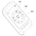
도13을 참조하면 조그휠(200) 또는 기타의 키버튼을 클릭하여 메뉴선택 모드를 선택하면 표시부(100)에 선택 가능한 메뉴가 디스플레이된다. 메뉴선택 모드의 경우 표시부(100)는 그 중앙부에 특정 모드 선택을 위한 터치영역(160)이 형성된다. 터치영역(160)은 원형으로 형성되며, 터치영역(160)의 외부에는 터치영역(160)을 중심으로 원주형태를 이루며 선택 가능한 메뉴 아이콘(162)이 디스플레이된다. 또한, 메뉴선택 모드에서는 조그휠(200) 또는 기타의 키버튼 클릭시 선택되는 모드를 알려주기 위하여 상기 아이콘(162) 중 어느 하나를 지시하는 인디케이 터(indicator)(164)가 디스플레이된다. 인디케이터(indicator)(164)는, 인디케이터(indicator)에 의해 지시되는 아이콘(162)이 디스플레이되었던 위치에 당해 아이콘(162)을 대체하며 화살표 등의 특정 형태로 디스플레이된다. 이때, 인디케이터(indicator)(164)에 의해 지시되는 아이콘(162)은 터치영역(160)에 디스플레이된다. 이때, 터치영역(160)을 터치하면 터치영역(160)에 디스플레이된 아이콘(162)이 나타내는 모드가 선택된다.Referring to FIG. 13, when the menu selection mode is selected by clicking the
도13 및 도14를 참조하면 메뉴선택 모드에서는 조그휠(200)이 양방향으로 회전함에 따라 표시부(100)에 디스플레이된 인디케이터(indicator)(164)는 선택적으로 시계방향 또는 반시계방향에 위치하는 다음 아이콘(162)을 지시하게 된다. 즉, 도13에는 인디케이터(indicator)(164)가 일정표 모드를 나타내는 아이콘을 지시함으로써 터치영역(160)에 일정표 모드를 나타내는 달력이 디스플레이되어 있다. 이 상태에서 조그휠(200)을 회전시켜 인디케이터(indicator)(164)가 카메라 모드를 나타내는 아이콘을 지시한 상태가 도14에 도시되어 있다. 도14를 참조하면 인디케이터(indicator)(164)가 카메라 모드를 나타내는 아이콘을 지시함으로써 터치영역(160)에 카메라 모드를 나타내는 카메라가 디스플레이되어 있음을 알 수 있다. 한편, 인디케이터(indicator)(164)는 조그휠(200)이 45° 회전한 상태에서 소정 시간 경과할 때마다 연속적으로 다음 아이콘(162)을 지시하게 된다.13 and 14, in the menu selection mode, as the
이하, 상기한 일실시예의 작동에 대해 설명한다.Hereinafter, the operation of the above-described embodiment will be described.
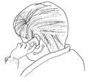
도1을 참조하면 상기한 일실시예는 단말기의 배면에 조그휠(200)이 위치하고, 조그휠(200)의 상단부가 단말기의 배면에 돌출 형성되므로, 사용자가 한 손으 로 단말기를 잡은 상태에서 단말기를 잡은 손의 검지를 사용하여 조그휠(200)을 용이하게 회전시킬 수 있게 된다. 따라서, 도15를 참조하면 사용자가 단말기를 한 손으로 쥐고 통화를 하는 경우 검지를 사용하여 용이하게 조그휠을 양방향으로 회전시킴으로써 선택적으로 통화음을 볼륨 업(volume up) 또는 볼륨 다운(volume down)시킬 수 있게 된다.Referring to FIG. 1, in the above embodiment, the
도1을 참조하면 상기한 일실시예는 표시부(100)가 단말기의 전방에 위치하므로 사용자가 표시부(100)에 디스플레이되는 영상을 보면서 조그휠(200)을 회전시킬 수 있게 된다. 따라서, 도16을 참조하면 사용자는 표시부(100)에 디스플레이되는 영상을 보면서 단말기를 잡은 손의 검지를 이용하여 조그휠(200)을 회전시키거나 클릭함으로써 편리하게 단말기를 조작할 수 있게 된다.Referring to FIG. 1, since the
도1을 참조하면 상기한 일실시예는 단말기 작동을 위한 조그휠(200)을 단말기의 배면에 위치시킴으로써 단말기 전면의 전영역을 표시부(100)로 할 수 있으므로 디스플레이 영역을 크게 구현할 수 있게 된다.Referring to FIG. 1, since the
도10을 참조하면 상기한 일실시예는 조그휠(200)에 마그네틱(812)이 장착되어 있어 조그휠(200) 회전시 마그네틱(812)이 함께 회전함으로써 연성회로기판(800)에 형성된 홀센서(810)에 자기장의 변화를 일으키므로 조그휠(200)의 회전방향을 감지할 수 있게 된다.Referring to FIG. 10, the
도5 및 도9를 참조하면 조그휠(200)이 시계방향 또는 반시계방향으로 45° 회전하는 경우 프레임(400)에 형성된 이동돌기(430)의 어느 하나가 조그휠(200)의 내면에 형성된 저지돌기(220)의 일측단에 걸림으로써 조그휠(200)의 회전이 저지된 다.5 and 9, when the
도6 및 도9를 참조하면 조그휠(200)이 시계방향 또는 반시계방향으로 회전하는 경우 토션스프링(240)의 돌출 단부가 프레임(400)에 형성된 이동돌기(430)에 걸려 압축되므로, 회전력 제거시 토션스프링(240)의 복원력에 의해 조그휠(200)이 최초의 설정위치로 복귀하게 된다.6 and 9, when the
도2 및 도6을 참조하면 프레임(400)에는 드러스트 와셔(thrust)(470)가 장착되어 드러스트 와셔(thrust)(470)가 조그휠(200)의 저지돌기(220)와 접촉하므로, 조그휠(200)과 프레임(400)의 직접 마찰이 방치되어 조그휠(200)을 부드럽게 회전시킬 수 있게 된다.2 and 6, the
도2를 참조하면 조그휠(200)이 프레임(400)에 안착된 경우 하부로부터 고정와셔(480)를 조그휠(200)의 하단부에 체결하므로 조그휠(200)과 프레임(400)의 결합이 용이하게 된다.Referring to FIG. 2, when the
도7 및 도8을 참조하면 렌즈커버(330)가 닫혀 있는 상태에서 코일스프링(340)에 탄성력이 작용하고 있으므로 외부에서 강제로 렌즈커버(330)를 개방하는 경우 상기한 탄성력 보다 큰 힘을 가하지 않는 한 렌즈커버(300)가 개방되지 않게 된다.Referring to FIGS. 7 and 8, when an elastic force is applied to the coil spring 340 in a state where the
도2 및 도8을 참조하면 모우터(700)가 회전함에 따라 상하이동돌기(720)가 상부로 이동하며 회전판(320)에 형성된 회전돌기(322)와 미끄럼 접촉하게 된다. 이때 상하이동돌기(720)는 회전돌기(322)의 경사면과 미끄럼 접촉하므로, 회전판(320)에는 수평방향의 힘이 발생하고, 이 수평방향의 힘에 의해 회전판(320)이 회전하게 된다. 도7을 참조하면 회전판(320)이 회전함에 따라 2개의 렌즈커버(330)가 힌지축을 중심으로 회전하며 상호 이격되며 고정판(310)에 형성된 통공을 개방하게 된다. 고정판(310)에 형성된 통공이 개방됨에 따라 카메라(500)의 렌즈가 외부에 노출된다.2 and 8, as the
도8을 참조하면 회전판(320) 회전시 코일스프링(340)이 변형되어 탄성에너지가 저장되므로, 모우터(700)를 역방향으로 회전시켜 상하이동돌기(720)를 하부로 이동시키면 코일스프링(340)에 저장된 탄성에너지에 의해 회전판(320)이 역방향으로 회전하여 렌즈커버(330)가 고정판(310)에 형성된 통공을 닫게 된다.Referring to FIG. 8, since the coil spring 340 is deformed and the elastic energy is stored when the rotating plate 320 rotates, the coil spring 340 is moved by rotating the
상기한 일실시예에 있어서, 조그휠(200)은 바 타입(bar type) 단말기의 배면에 구비되는 것으로 하였으나, 다른 실시예의 경우 조그휠(200)은 폴더 타입(folder type) 단말기의 배면에 구비될 수도 있다. 이 경우 표시부(100)는 단말기의 본체 또는 폴더에 구비되어 폴더 개방시 단말기의 전방에 노출 가능하거나, 폴더의 전면에 구비되어 폴더가 닫힌 상태에서 단말기의 전방에 노출 가능하여야 한다. In the above embodiment, the
본 발명은 단말기의 배면에 조그휠이 위치하고, 조그휠의 상단부가 단말기의 배면에 돌출 형성되므로, 사용자가 한 손으로 단말기를 잡은 상태에서 단말기를 잡은 손의 검지를 사용하여 조그휠을 용이하게 회전시킬 수 있는 장점이 있다. 따라서, 사용자가 단말기를 한 손으로 잡고 통화를 하는 경우 단말기를 잡은 손의 검지를 사용하여 용이하게 조그휠을 양방향으로 회전시킴으로써 선택적으로 통화음을 볼륨 업(volume up) 또는 볼륨 다운(volume down)시킬 수 있는 장점이 있다.In the present invention, the jog wheel is positioned on the back of the terminal, and the upper end of the jog wheel is formed to protrude on the back of the terminal, so that the user can easily rotate the jog wheel using the index finger of the hand holding the terminal while holding the terminal with one hand. There is an advantage to this. Therefore, when a user makes a call while holding the terminal with one hand, the user can selectively rotate up or down the volume by using the index finger of the hand holding the terminal to rotate the jog wheel in both directions. There are advantages to it.
본 발명은 표시부가 단말기의 전방에 위치하므로 사용자가 표시부에 디스플레이되는 영상을 보면서 조그휠을 회전시킬 수 있는 장점이 있다. 즉, 사용자는 표시부에 디스플레이되는 영상을 보면서 단말기를 잡은 손의 검지를 이용하여 조그휠을 회전시키거나 클릭함으로써 편리하게 단말기를 조작할 수 있게 된다.The present invention has the advantage that the user can rotate the jog wheel while watching the image displayed on the display unit is located in front of the terminal. That is, the user can conveniently operate the terminal by rotating or clicking the jog wheel using the index finger of the hand holding the terminal while watching the image displayed on the display unit.
본 발명은 단말기 작동을 위한 조그휠을 단말기의 배면에 위치시킴으로써 단말기 전면의 전영역을 표시부로 할 수 있으므로 디스플레이 영역을 크게 구현할 수 있는 장점이 있다.The present invention has the advantage that the display area can be largely implemented because the entire area of the front of the terminal can be a display unit by placing the jog wheel for operating the terminal on the back of the terminal.
본 발명은 메뉴선택 모드로의 전환시 표시부의 중앙부에 특정 모드 선택을 위한 터치영역이 형성되고, 터치영역을 중심으로 원주형태를 이루며 선택 가능한 메뉴 아이콘이 디스플레이되며, 인디케이터(indicator)에 의해 지시되는 아이콘은 터치영역에 디스플레이되므로, 메뉴선택 모드의 표시부의 외관이 수려한 장점이 있다.According to the present invention, when switching to the menu selection mode, a touch area for selecting a specific mode is formed at the center of the display unit, a selectable menu icon is displayed in a circumferential shape around the touch area, and is indicated by an indicator. Since the icon is displayed in the touch area, the appearance of the display unit in the menu selection mode is advantageous.
본 발명은 조그휠에 가해진 회전력이 제거되는 경우 토션스프링의 복원력에 의해 조그휠이 최초의 설정위치로 복귀하게 되므로, 조그휠 클릭시 모드 선택 위치가 일정하게 유지되는 장점이 있다.The present invention has the advantage that the mode selection position is kept constant when the jog wheel is clicked because the jog wheel returns to the initial setting position by the restoring force of the torsion spring when the rotation force applied to the jog wheel is removed.
본 발명은 조그휠이 프레임에 안착된 경우 하부로부터 고정와셔를 조그휠의 하단부에 체결하므로 조그휠과 프레임의 결합이 용이한 장점이 있다.When the jog wheel is seated on the frame, the fixing washer is fastened from the lower portion to the lower end of the jog wheel, so that the jog wheel and the frame are easily coupled.
본 발명은 렌즈커버가 닫혀 있는 상태에서 코일스프링에 탄성력이 작용하고 있으므로 외부에서 강제로 렌즈커버를 개방하는 경우 상기한 탄성력 보다 큰 힘을 가하지 않는 한 렌즈커버가 개방되지 않게 되어 카레라의 렌즈가 보호되는 장점이 있다.In the present invention, the elastic force is applied to the coil spring while the lens cover is closed, so when the lens cover is forcibly opened from the outside, the lens cover is not opened unless a force greater than the aforementioned elastic force is applied to protect the lens of the Carrera. It has the advantage of being.
Claims (27)
Translated fromKoreanPriority Applications (7)
| Application Number | Priority Date | Filing Date | Title |
|---|---|---|---|
| KR1020070004212AKR100896055B1 (en) | 2007-01-15 | 2007-01-15 | Mobile terminal with rotary input device and display method thereof |
| EP08000578AEP1944681A3 (en) | 2007-01-15 | 2008-01-14 | Mobile terminal having rotating input device and method for operating the mobile terminal |
| EP08000651.3AEP1944677B1 (en) | 2007-01-15 | 2008-01-15 | Mobile terminal having a rotatable input device |
| CN2008100856312ACN101232687B (en) | 2007-01-15 | 2008-01-15 | Mobile terminal having rotating input device and method for operating the mobile terminal |
| CN2008100856327ACN101232528B (en) | 2007-01-15 | 2008-01-15 | Mobile terminal having rotating input device |
| US12/014,608US7765495B2 (en) | 2007-01-15 | 2008-01-15 | Mobile terminal having rotating input device and method for operating the mobile terminal |
| US12/014,585US8005506B2 (en) | 2007-01-15 | 2008-01-15 | Mobile terminal having rotating input device |
Applications Claiming Priority (1)
| Application Number | Priority Date | Filing Date | Title |
|---|---|---|---|
| KR1020070004212AKR100896055B1 (en) | 2007-01-15 | 2007-01-15 | Mobile terminal with rotary input device and display method thereof |
Publications (2)
| Publication Number | Publication Date |
|---|---|
| KR20080067079A KR20080067079A (en) | 2008-07-18 |
| KR100896055B1true KR100896055B1 (en) | 2009-05-07 |
Family
ID=39301075
Family Applications (1)
| Application Number | Title | Priority Date | Filing Date |
|---|---|---|---|
| KR1020070004212AExpired - Fee RelatedKR100896055B1 (en) | 2007-01-15 | 2007-01-15 | Mobile terminal with rotary input device and display method thereof |
Country Status (4)
| Country | Link |
|---|---|
| US (2) | US7765495B2 (en) |
| EP (2) | EP1944681A3 (en) |
| KR (1) | KR100896055B1 (en) |
| CN (2) | CN101232687B (en) |
Cited By (1)
| Publication number | Priority date | Publication date | Assignee | Title |
|---|---|---|---|---|
| KR20110093090A (en)* | 2010-02-11 | 2011-08-18 | 엘지전자 주식회사 | Mobile terminal |
Families Citing this family (83)
| Publication number | Priority date | Publication date | Assignee | Title |
|---|---|---|---|---|
| KR100896055B1 (en)* | 2007-01-15 | 2009-05-07 | 엘지전자 주식회사 | Mobile terminal with rotary input device and display method thereof |
| USD592674S1 (en)* | 2008-01-03 | 2009-05-19 | Samsung Electronics Co., Ltd. | Display image for a mobile phone |
| US20100042954A1 (en)* | 2008-08-12 | 2010-02-18 | Apple Inc. | Motion based input selection |
| CN101661146B (en)* | 2008-08-28 | 2012-10-17 | 深圳富泰宏精密工业有限公司 | Engaged structure |
| US20100064255A1 (en)* | 2008-09-05 | 2010-03-11 | Apple Inc. | Contextual menus in an electronic device |
| US20100225585A1 (en)* | 2009-03-05 | 2010-09-09 | Research In Motion Limited | Method for navigating and selecting items with a return-to-center navigation component |
| EP2226714A1 (en) | 2009-03-05 | 2010-09-08 | Research In Motion Limited | Method for navigating and selecting items with a return-to-center navigation component |
| KR101576181B1 (en)* | 2009-03-11 | 2015-12-09 | 삼성전자주식회사 | The mechanical information input / output device |
| US20100281430A1 (en)* | 2009-05-02 | 2010-11-04 | Samir Hanna Safar | Mobile applications spin menu |
| US20110109560A1 (en) | 2009-11-06 | 2011-05-12 | Santiago Carvajal | Audio/Visual Device Touch-Based User Interface |
| US9201584B2 (en) | 2009-11-06 | 2015-12-01 | Bose Corporation | Audio/visual device user interface with tactile feedback |
| US8638306B2 (en) | 2009-11-06 | 2014-01-28 | Bose Corporation | Touch-based user interface corner conductive pad |
| WO2011057076A1 (en)* | 2009-11-06 | 2011-05-12 | Bose Corporation | Audio/visual device touch-based user interface |
| US8350820B2 (en) | 2009-11-06 | 2013-01-08 | Bose Corporation | Touch-based user interface user operation accuracy enhancement |
| USD687843S1 (en) | 2009-11-06 | 2013-08-13 | Bose Corporation | Audio/video device with graphical user interface |
| US8692815B2 (en) | 2009-11-06 | 2014-04-08 | Bose Corporation | Touch-based user interface user selection accuracy enhancement |
| US9354726B2 (en) | 2009-11-06 | 2016-05-31 | Bose Corporation | Audio/visual device graphical user interface submenu |
| US8669949B2 (en) | 2009-11-06 | 2014-03-11 | Bose Corporation | Touch-based user interface touch sensor power |
| US8601394B2 (en)* | 2009-11-06 | 2013-12-03 | Bose Corporation | Graphical user interface user customization |
| US8686957B2 (en) | 2009-11-06 | 2014-04-01 | Bose Corporation | Touch-based user interface conductive rings |
| US20110113368A1 (en) | 2009-11-06 | 2011-05-12 | Santiago Carvajal | Audio/Visual Device Graphical User Interface |
| USD665417S1 (en)* | 2010-03-03 | 2012-08-14 | Sony Corporation | Display panel or screen portion with icon |
| US20110291946A1 (en)* | 2010-05-26 | 2011-12-01 | T-Mobile Usa, Inc. | Touchpad interaction |
| US20120089948A1 (en)* | 2010-10-11 | 2012-04-12 | Third Wave Power Pte Ltd | Gesture controlled user interface |
| US9569002B2 (en) | 2010-12-17 | 2017-02-14 | Blackberry Limited | Portable electronic device having a sensor arrangement for gesture recognition |
| US20140192626A1 (en)* | 2011-03-02 | 2014-07-10 | Royal Hali Iplik Tekstil Mobilya Sanayi Ve Ticaret Anonim Sirketi | Talking Dome Watch for the Visually Impaired |
| CN102142028B (en)* | 2011-03-18 | 2016-06-15 | 鸿富锦精密工业(深圳)有限公司 | Electronics and file path display method thereof |
| US8707211B2 (en)* | 2011-10-21 | 2014-04-22 | Hewlett-Packard Development Company, L.P. | Radial graphical user interface |
| CN102361489B (en)* | 2011-10-27 | 2015-09-23 | 捷开通讯科技(上海)有限公司 | The dialing mechanism of mobile terminal |
| CN103176725B (en)* | 2011-12-21 | 2017-06-13 | 富泰华工业(深圳)有限公司 | file operating system and file operation method |
| USD690318S1 (en)* | 2012-01-12 | 2013-09-24 | Lenovo (Singapore) Pte. Ltd. | Information handling device with graphical user interface |
| KR101397084B1 (en) | 2012-07-02 | 2014-05-20 | 엘지전자 주식회사 | Mobile terminal |
| CN203118837U (en)* | 2012-10-18 | 2013-08-07 | 中兴通讯股份有限公司 | Mobile terminal button assembly |
| USD743992S1 (en)* | 2012-10-31 | 2015-11-24 | Lg Electronics Inc. | Television with graphical user interface |
| USD732050S1 (en)* | 2012-10-31 | 2015-06-16 | Lg Electronics Inc. | Television with graphical user interface |
| USD730917S1 (en)* | 2012-10-31 | 2015-06-02 | Lg Electronics Inc. | Television with graphical user interface |
| US10551928B2 (en) | 2012-11-20 | 2020-02-04 | Samsung Electronics Company, Ltd. | GUI transitions on wearable electronic device |
| US11157436B2 (en) | 2012-11-20 | 2021-10-26 | Samsung Electronics Company, Ltd. | Services associated with wearable electronic device |
| US10423214B2 (en) | 2012-11-20 | 2019-09-24 | Samsung Electronics Company, Ltd | Delegating processing from wearable electronic device |
| US10185416B2 (en) | 2012-11-20 | 2019-01-22 | Samsung Electronics Co., Ltd. | User gesture input to wearable electronic device involving movement of device |
| US9477313B2 (en) | 2012-11-20 | 2016-10-25 | Samsung Electronics Co., Ltd. | User gesture input to wearable electronic device involving outward-facing sensor of device |
| US11237719B2 (en) | 2012-11-20 | 2022-02-01 | Samsung Electronics Company, Ltd. | Controlling remote electronic device with wearable electronic device |
| US8994827B2 (en) | 2012-11-20 | 2015-03-31 | Samsung Electronics Co., Ltd | Wearable electronic device |
| US11372536B2 (en)* | 2012-11-20 | 2022-06-28 | Samsung Electronics Company, Ltd. | Transition and interaction model for wearable electronic device |
| US11513675B2 (en) | 2012-12-29 | 2022-11-29 | Apple Inc. | User interface for manipulating user interface objects |
| KR101398141B1 (en) | 2013-02-08 | 2014-05-20 | 엘지전자 주식회사 | Mobile terminal |
| USD745533S1 (en)* | 2013-08-27 | 2015-12-15 | Tencent Technology (Shenzhen) Company Limited | Display screen or a portion thereof with graphical user interface |
| US10503388B2 (en) | 2013-09-03 | 2019-12-10 | Apple Inc. | Crown input for a wearable electronic device |
| US10545657B2 (en) | 2013-09-03 | 2020-01-28 | Apple Inc. | User interface for manipulating user interface objects |
| KR102111452B1 (en)* | 2013-09-03 | 2020-05-15 | 애플 인크. | User interface for manipulating user interface objects |
| CN110795005A (en) | 2013-09-03 | 2020-02-14 | 苹果公司 | User interface for manipulating user interface objects using magnetic properties |
| US11068128B2 (en) | 2013-09-03 | 2021-07-20 | Apple Inc. | User interface object manipulations in a user interface |
| US12287962B2 (en) | 2013-09-03 | 2025-04-29 | Apple Inc. | User interface for manipulating user interface objects |
| CN103533486B (en)* | 2013-09-24 | 2016-12-07 | 青岛歌尔声学科技有限公司 | A kind of external volume regulator and control method |
| USD753708S1 (en)* | 2013-12-30 | 2016-04-12 | Beijing Qihoo Technology Co. Ltd | Display screen or portion thereof with animated graphical user interface |
| US10691332B2 (en) | 2014-02-28 | 2020-06-23 | Samsung Electronics Company, Ltd. | Text input on an interactive display |
| CN103916497A (en)* | 2014-03-25 | 2014-07-09 | 京东方科技集团股份有限公司 | Auxiliary equipment of mobile terminal and mobile terminal product |
| CN104007824B (en)* | 2014-06-10 | 2017-04-19 | 北京芯创睿胜科技有限公司 | Equipment and method of using active circular shell as input device |
| CN105204796B (en)* | 2014-06-17 | 2019-01-15 | 联想(北京)有限公司 | A kind of information processing method and electronic equipment |
| EP3147747A1 (en) | 2014-06-27 | 2017-03-29 | Apple Inc. | Manipulation of calendar application in device with touch screen |
| TWI647608B (en) | 2014-07-21 | 2019-01-11 | 美商蘋果公司 | Remote user interface |
| KR102511376B1 (en) | 2014-08-02 | 2023-03-17 | 애플 인크. | Context-specific user interfaces |
| TWI582641B (en) | 2014-09-02 | 2017-05-11 | 蘋果公司 | Button functionality |
| TWI676127B (en) | 2014-09-02 | 2019-11-01 | 美商蘋果公司 | Method, system, electronic device and computer-readable storage medium regarding electronic mail user interface |
| CN106662966B (en) | 2014-09-02 | 2020-08-18 | 苹果公司 | Multi-dimensional object rearrangement |
| CN106797493A (en) | 2014-09-02 | 2017-05-31 | 苹果公司 | Music user interface |
| US20160062571A1 (en)* | 2014-09-02 | 2016-03-03 | Apple Inc. | Reduced size user interface |
| US10365807B2 (en) | 2015-03-02 | 2019-07-30 | Apple Inc. | Control of system zoom magnification using a rotatable input mechanism |
| CN104731452B (en)* | 2015-03-18 | 2018-07-06 | 联想(北京)有限公司 | A kind of display control method and electronic equipment |
| WO2016171467A1 (en) | 2015-04-23 | 2016-10-27 | Samsung Electronics Co., Ltd. | Electronic device including rotary member and display method thereof |
| CN105068712B (en)* | 2015-08-06 | 2019-04-30 | Tcl移动通信科技(宁波)有限公司 | A kind of menu selection realization method and system of intelligent wearable device |
| USD804514S1 (en)* | 2015-08-21 | 2017-12-05 | Toyota Jidosha Kabushiki Kaisha | Display screen with graphical user interface |
| CN105242524A (en)* | 2015-09-09 | 2016-01-13 | 南京物联传感技术有限公司 | Graphical interface interaction intelligent watch and using method thereof |
| DK201670595A1 (en) | 2016-06-11 | 2018-01-22 | Apple Inc | Configuring context-specific user interfaces |
| AU2017100667A4 (en) | 2016-06-11 | 2017-07-06 | Apple Inc. | Activity and workout updates |
| US10178306B2 (en) | 2016-06-16 | 2019-01-08 | Tracfone Wireless, Inc. | Wireless device having dedicated rear panel control |
| CN114710585B (en)* | 2017-11-23 | 2023-10-13 | 华为技术有限公司 | A photography method, terminal and storage medium |
| USD924247S1 (en)* | 2018-03-22 | 2021-07-06 | Leica Microsystems Cms Gmbh | Microscope display screen with graphical user interface |
| US11622067B2 (en)* | 2018-05-31 | 2023-04-04 | Kohler Co. | Connected bathroom components |
| US11435830B2 (en) | 2018-09-11 | 2022-09-06 | Apple Inc. | Content-based tactile outputs |
| US10712824B2 (en) | 2018-09-11 | 2020-07-14 | Apple Inc. | Content-based tactile outputs |
| US11893212B2 (en) | 2021-06-06 | 2024-02-06 | Apple Inc. | User interfaces for managing application widgets |
| USD1095567S1 (en)* | 2024-06-05 | 2025-09-30 | Big Fish Games, Inc. | Display screen or portion thereof with a transitional graphical user interface |
Citations (4)
| Publication number | Priority date | Publication date | Assignee | Title |
|---|---|---|---|---|
| JPH08123647A (en)* | 1994-10-25 | 1996-05-17 | Sharp Corp | Information processing device |
| JP2004032548A (en)* | 2002-06-27 | 2004-01-29 | Alps Electric Co Ltd | Mobile terminal |
| JP2004157640A (en)* | 2002-11-05 | 2004-06-03 | Sony Ericsson Mobilecommunications Japan Inc | Portable terminal device |
| JP2005092667A (en)* | 2003-09-19 | 2005-04-07 | Sony Ericsson Mobilecommunications Japan Inc | Portable information input device |
Family Cites Families (33)
| Publication number | Priority date | Publication date | Assignee | Title |
|---|---|---|---|---|
| GB2330981B (en)* | 1997-10-31 | 2002-07-03 | Nokia Mobile Phones Ltd | A radiotelephone handset |
| GB2330982B (en)* | 1997-10-31 | 2002-02-06 | Nokia Mobile Phones Ltd | A radiotelephone handset |
| US20060250355A1 (en)* | 1998-05-29 | 2006-11-09 | Miller-Smith Richard M | Image control system |
| DE19855022A1 (en)* | 1998-11-20 | 2000-05-25 | Inst Halbleiterphysik Gmbh | Mobile telecommunications unit, containing mobile telephone, with improved operational comfort by special software menu |
| JP2001357758A (en)* | 2000-06-12 | 2001-12-26 | Alps Electric Co Ltd | Combined control input device |
| US6556222B1 (en)* | 2000-06-30 | 2003-04-29 | International Business Machines Corporation | Bezel based input mechanism and user interface for a smart watch |
| JP2003084910A (en) | 2001-09-14 | 2003-03-20 | Nemoto Kyorindo:Kk | Input operation device and image display device |
| AU2003217586A1 (en) | 2002-02-21 | 2003-09-09 | Mobicom Corporation | Article comprising an adaptable input device abstract |
| JP4235393B2 (en)* | 2002-03-11 | 2009-03-11 | 富士フイルム株式会社 | Index image display control device |
| US7111788B2 (en)* | 2002-04-22 | 2006-09-26 | Nokia Corporation | System and method for navigating applications using a graphical user interface |
| US7001435B2 (en) | 2002-05-30 | 2006-02-21 | Automotive Technology, Inc. | Leather treatment |
| JP4338364B2 (en)* | 2002-07-02 | 2009-10-07 | ソニー株式会社 | Portable information communication terminal, program, and recording medium recording the program |
| US6968508B2 (en)* | 2002-07-30 | 2005-11-22 | Motorola, Inc. | Rotating user interface |
| KR100810300B1 (en) | 2002-10-15 | 2008-03-06 | 삼성전자주식회사 | Portable communication device |
| JP2004295159A (en)* | 2003-02-07 | 2004-10-21 | Sony Corp | Icon display system and method, electronic equipment, and computer program |
| JP2004259063A (en)* | 2003-02-26 | 2004-09-16 | Sony Corp | Device and method for display processing for three dimensional object and computer program |
| KR100617681B1 (en)* | 2003-04-15 | 2006-08-28 | 삼성전자주식회사 | How to Use the Rotating Key Device of a Portable Terminal |
| EP1655953A4 (en)* | 2003-08-14 | 2008-05-07 | Matsushita Electric Industrial Co Ltd | USER INTERFACE SYSTEM, PROGRAM, AND RECORDING MEDIUM |
| JP4439225B2 (en) | 2003-09-08 | 2010-03-24 | 日本電産コパル株式会社 | Lens barrier device |
| JP2006119368A (en) | 2004-10-21 | 2006-05-11 | Konica Minolta Opto Inc | Wide-angle optical system, imaging lens device, monitor camera and digital equipment |
| US20060095865A1 (en)* | 2004-11-04 | 2006-05-04 | Rostom Mohamed A | Dynamic graphical user interface for a desktop environment |
| JP4731882B2 (en)* | 2004-11-09 | 2011-07-27 | キヤノン株式会社 | Lens barrel with lens barrier and camera |
| KR101050607B1 (en)* | 2004-11-24 | 2011-07-19 | 삼성전자주식회사 | Camera zoom device and method in a mobile communication terminal |
| FR2878646B1 (en)* | 2004-11-26 | 2007-02-09 | Itt Mfg Enterprises Inc | ELECTRICAL SWITCH WITH MULTIPLE SWITCHES |
| EP1684158A1 (en)* | 2005-01-22 | 2006-07-26 | MobiNote Technology Corp. | Module and method for controlling a portable multimedia audio and video recorder/player |
| US20060250640A1 (en)* | 2005-05-09 | 2006-11-09 | Silverbrook Research Pty Ltd | Method of reading coded data from a print medium before printing |
| US20070030963A1 (en) | 2005-08-04 | 2007-02-08 | Apple Computer, Inc. | Securing and controlling access to digital data |
| US7860536B2 (en) | 2006-01-05 | 2010-12-28 | Apple Inc. | Telephone interface for a portable communication device |
| CN101075163A (en) | 2006-05-19 | 2007-11-21 | 鸿富锦精密工业(深圳)有限公司 | Manual device for inputting character by runner |
| US8564543B2 (en)* | 2006-09-11 | 2013-10-22 | Apple Inc. | Media player with imaged based browsing |
| US7714839B2 (en) | 2006-09-29 | 2010-05-11 | Sony Ericsson Mobile Communications Ab | Jog dial for mobile terminal |
| US7667148B2 (en) | 2006-10-13 | 2010-02-23 | Apple Inc. | Method, device, and graphical user interface for dialing with a click wheel |
| KR100896055B1 (en)* | 2007-01-15 | 2009-05-07 | 엘지전자 주식회사 | Mobile terminal with rotary input device and display method thereof |
- 2007
- 2007-01-15KRKR1020070004212Apatent/KR100896055B1/ennot_activeExpired - Fee Related
- 2008
- 2008-01-14EPEP08000578Apatent/EP1944681A3/ennot_activeWithdrawn
- 2008-01-15EPEP08000651.3Apatent/EP1944677B1/ennot_activeNot-in-force
- 2008-01-15USUS12/014,608patent/US7765495B2/ennot_activeExpired - Fee Related
- 2008-01-15USUS12/014,585patent/US8005506B2/ennot_activeExpired - Fee Related
- 2008-01-15CNCN2008100856312Apatent/CN101232687B/ennot_activeExpired - Fee Related
- 2008-01-15CNCN2008100856327Apatent/CN101232528B/ennot_activeExpired - Fee Related
Patent Citations (4)
| Publication number | Priority date | Publication date | Assignee | Title |
|---|---|---|---|---|
| JPH08123647A (en)* | 1994-10-25 | 1996-05-17 | Sharp Corp | Information processing device |
| JP2004032548A (en)* | 2002-06-27 | 2004-01-29 | Alps Electric Co Ltd | Mobile terminal |
| JP2004157640A (en)* | 2002-11-05 | 2004-06-03 | Sony Ericsson Mobilecommunications Japan Inc | Portable terminal device |
| JP2005092667A (en)* | 2003-09-19 | 2005-04-07 | Sony Ericsson Mobilecommunications Japan Inc | Portable information input device |
Cited By (2)
| Publication number | Priority date | Publication date | Assignee | Title |
|---|---|---|---|---|
| KR20110093090A (en)* | 2010-02-11 | 2011-08-18 | 엘지전자 주식회사 | Mobile terminal |
| KR101649646B1 (en) | 2010-02-11 | 2016-08-19 | 엘지전자 주식회사 | Portable terminal |
Also Published As
| Publication number | Publication date |
|---|---|
| EP1944681A2 (en) | 2008-07-16 |
| CN101232528B (en) | 2012-05-30 |
| KR20080067079A (en) | 2008-07-18 |
| CN101232687B (en) | 2013-06-12 |
| EP1944677A2 (en) | 2008-07-16 |
| CN101232528A (en) | 2008-07-30 |
| EP1944677A3 (en) | 2009-06-17 |
| EP1944677B1 (en) | 2018-09-19 |
| CN101232687A (en) | 2008-07-30 |
| EP1944681A3 (en) | 2009-06-10 |
| US20080171572A1 (en) | 2008-07-17 |
| US8005506B2 (en) | 2011-08-23 |
| US7765495B2 (en) | 2010-07-27 |
| US20080172634A1 (en) | 2008-07-17 |
Similar Documents
| Publication | Publication Date | Title |
|---|---|---|
| KR100896055B1 (en) | Mobile terminal with rotary input device and display method thereof | |
| US8508511B2 (en) | Inputting device | |
| KR100931434B1 (en) | Operation input device and electronic device using the same | |
| JP4075335B2 (en) | Electronics | |
| JP2006073311A (en) | Operation input device and electronic equipment using this | |
| KR101986124B1 (en) | Switch apparatus for an automobile | |
| US20090295984A1 (en) | Image pickup apparatus | |
| KR100920290B1 (en) | Operation input device and electronic instrument of use thereof | |
| US8368651B2 (en) | Input device | |
| JP2009171085A (en) | Electronic device | |
| JP2012216353A (en) | Push button device having dust-proof and drip-proof mechanism | |
| JP3995363B2 (en) | Controller used for game consoles | |
| JP2007080279A (en) | Electronics | |
| JP2014089814A (en) | Input device | |
| JP2014060030A (en) | Rotary electronic component | |
| JP2011192413A (en) | Operation switch and portable terminal | |
| KR20090122132A (en) | Input device and electronic device equipped with the input device | |
| JP5292198B2 (en) | Input device | |
| JP5483648B1 (en) | Input device | |
| JPH117073A (en) | Camera contact type setting device | |
| JP2012243613A (en) | Switch device | |
| KR20110100576A (en) | Operation switch and portable terminal | |
| JP2012113263A (en) | Imaging apparatus | |
| JP2007103140A (en) | Multi-direction input device | |
| KR20090054035A (en) | Hinge device for mouse of electronic device |
Legal Events
| Date | Code | Title | Description |
|---|---|---|---|
| PA0109 | Patent application | St.27 status event code:A-0-1-A10-A12-nap-PA0109 | |
| R17-X000 | Change to representative recorded | St.27 status event code:A-3-3-R10-R17-oth-X000 | |
| A201 | Request for examination | ||
| A302 | Request for accelerated examination | ||
| PA0201 | Request for examination | St.27 status event code:A-1-2-D10-D11-exm-PA0201 | |
| PA0302 | Request for accelerated examination | St.27 status event code:A-1-2-D10-D17-exm-PA0302 St.27 status event code:A-1-2-D10-D16-exm-PA0302 | |
| D13-X000 | Search requested | St.27 status event code:A-1-2-D10-D13-srh-X000 | |
| P11-X000 | Amendment of application requested | St.27 status event code:A-2-2-P10-P11-nap-X000 | |
| P13-X000 | Application amended | St.27 status event code:A-2-2-P10-P13-nap-X000 | |
| D14-X000 | Search report completed | St.27 status event code:A-1-2-D10-D14-srh-X000 | |
| E902 | Notification of reason for refusal | ||
| PE0902 | Notice of grounds for rejection | St.27 status event code:A-1-2-D10-D21-exm-PE0902 | |
| E13-X000 | Pre-grant limitation requested | St.27 status event code:A-2-3-E10-E13-lim-X000 | |
| P11-X000 | Amendment of application requested | St.27 status event code:A-2-2-P10-P11-nap-X000 | |
| P13-X000 | Application amended | St.27 status event code:A-2-2-P10-P13-nap-X000 | |
| PG1501 | Laying open of application | St.27 status event code:A-1-1-Q10-Q12-nap-PG1501 | |
| E902 | Notification of reason for refusal | ||
| PE0902 | Notice of grounds for rejection | St.27 status event code:A-1-2-D10-D21-exm-PE0902 | |
| PN2301 | Change of applicant | St.27 status event code:A-3-3-R10-R13-asn-PN2301 St.27 status event code:A-3-3-R10-R11-asn-PN2301 | |
| E13-X000 | Pre-grant limitation requested | St.27 status event code:A-2-3-E10-E13-lim-X000 | |
| P11-X000 | Amendment of application requested | St.27 status event code:A-2-2-P10-P11-nap-X000 | |
| P13-X000 | Application amended | St.27 status event code:A-2-2-P10-P13-nap-X000 | |
| E90F | Notification of reason for final refusal | ||
| PE0902 | Notice of grounds for rejection | St.27 status event code:A-1-2-D10-D21-exm-PE0902 | |
| P11-X000 | Amendment of application requested | St.27 status event code:A-2-2-P10-P11-nap-X000 | |
| P13-X000 | Application amended | St.27 status event code:A-2-2-P10-P13-nap-X000 | |
| E701 | Decision to grant or registration of patent right | ||
| PE0701 | Decision of registration | St.27 status event code:A-1-2-D10-D22-exm-PE0701 | |
| GRNT | Written decision to grant | ||
| PR0701 | Registration of establishment | St.27 status event code:A-2-4-F10-F11-exm-PR0701 | |
| R18-X000 | Changes to party contact information recorded | St.27 status event code:A-5-5-R10-R18-oth-X000 | |
| PR1002 | Payment of registration fee | St.27 status event code:A-2-2-U10-U11-oth-PR1002 Fee payment year number:1 | |
| PG1601 | Publication of registration | St.27 status event code:A-4-4-Q10-Q13-nap-PG1601 | |
| R18-X000 | Changes to party contact information recorded | St.27 status event code:A-5-5-R10-R18-oth-X000 | |
| PR1001 | Payment of annual fee | St.27 status event code:A-4-4-U10-U11-oth-PR1001 Fee payment year number:4 | |
| FPAY | Annual fee payment | Payment date:20130326 Year of fee payment:5 | |
| PR1001 | Payment of annual fee | St.27 status event code:A-4-4-U10-U11-oth-PR1001 Fee payment year number:5 | |
| FPAY | Annual fee payment | Payment date:20140414 Year of fee payment:6 | |
| PR1001 | Payment of annual fee | St.27 status event code:A-4-4-U10-U11-oth-PR1001 Fee payment year number:6 | |
| PR1001 | Payment of annual fee | St.27 status event code:A-4-4-U10-U11-oth-PR1001 Fee payment year number:7 | |
| PN2301 | Change of applicant | St.27 status event code:A-5-5-R10-R13-asn-PN2301 St.27 status event code:A-5-5-R10-R11-asn-PN2301 | |
| FPAY | Annual fee payment | Payment date:20160324 Year of fee payment:8 | |
| PR1001 | Payment of annual fee | St.27 status event code:A-4-4-U10-U11-oth-PR1001 Fee payment year number:8 | |
| FPAY | Annual fee payment | Payment date:20170324 Year of fee payment:9 | |
| PR1001 | Payment of annual fee | St.27 status event code:A-4-4-U10-U11-oth-PR1001 Fee payment year number:9 | |
| LAPS | Lapse due to unpaid annual fee | ||
| PC1903 | Unpaid annual fee | St.27 status event code:A-4-4-U10-U13-oth-PC1903 Not in force date:20180428 Payment event data comment text:Termination Category : DEFAULT_OF_REGISTRATION_FEE | |
| PC1903 | Unpaid annual fee | St.27 status event code:N-4-6-H10-H13-oth-PC1903 Ip right cessation event data comment text:Termination Category : DEFAULT_OF_REGISTRATION_FEE Not in force date:20180428 | |
| PN2301 | Change of applicant | St.27 status event code:A-5-5-R10-R13-asn-PN2301 St.27 status event code:A-5-5-R10-R11-asn-PN2301 |