KR100891660B1 - Refresh device - Google Patents
Refresh deviceDownload PDFInfo
- Publication number
- KR100891660B1 KR100891660B1KR1020050019105AKR20050019105AKR100891660B1KR 100891660 B1KR100891660 B1KR 100891660B1KR 1020050019105 AKR1020050019105 AKR 1020050019105AKR 20050019105 AKR20050019105 AKR 20050019105AKR 100891660 B1KR100891660 B1KR 100891660B1
- Authority
- KR
- South Korea
- Prior art keywords
- steam
- unit
- base
- water storage
- storage unit
- Prior art date
- Legal status (The legal status is an assumption and is not a legal conclusion. Google has not performed a legal analysis and makes no representation as to the accuracy of the status listed.)
- Expired - Fee Related
Links
Images


Classifications
- D—TEXTILES; PAPER
- D06—TREATMENT OF TEXTILES OR THE LIKE; LAUNDERING; FLEXIBLE MATERIALS NOT OTHERWISE PROVIDED FOR
- D06F—LAUNDERING, DRYING, IRONING, PRESSING OR FOLDING TEXTILE ARTICLES
- D06F73/00—Apparatus for smoothing or removing creases from garments or other textile articles by formers, cores, stretchers, or internal frames, with the application of heat or steam
- D06F73/02—Apparatus for smoothing or removing creases from garments or other textile articles by formers, cores, stretchers, or internal frames, with the application of heat or steam having one or more treatment chambers
- A—HUMAN NECESSITIES
- A61—MEDICAL OR VETERINARY SCIENCE; HYGIENE
- A61L—METHODS OR APPARATUS FOR STERILISING MATERIALS OR OBJECTS IN GENERAL; DISINFECTION, STERILISATION OR DEODORISATION OF AIR; CHEMICAL ASPECTS OF BANDAGES, DRESSINGS, ABSORBENT PADS OR SURGICAL ARTICLES; MATERIALS FOR BANDAGES, DRESSINGS, ABSORBENT PADS OR SURGICAL ARTICLES
- A61L2/00—Methods or apparatus for disinfecting or sterilising materials or objects other than foodstuffs or contact lenses; Accessories therefor
- A61L2/02—Methods or apparatus for disinfecting or sterilising materials or objects other than foodstuffs or contact lenses; Accessories therefor using physical phenomena
- A61L2/04—Heat
- A61L2/06—Hot gas
- A61L2/07—Steam
- D—TEXTILES; PAPER
- D06—TREATMENT OF TEXTILES OR THE LIKE; LAUNDERING; FLEXIBLE MATERIALS NOT OTHERWISE PROVIDED FOR
- D06F—LAUNDERING, DRYING, IRONING, PRESSING OR FOLDING TEXTILE ARTICLES
- D06F58/00—Domestic laundry dryers
- D06F58/10—Drying cabinets or drying chambers having heating or ventilating means
- D06F58/14—Collapsible drying cabinets; Wall mounted collapsible hoods
- D—TEXTILES; PAPER
- D06—TREATMENT OF TEXTILES OR THE LIKE; LAUNDERING; FLEXIBLE MATERIALS NOT OTHERWISE PROVIDED FOR
- D06F—LAUNDERING, DRYING, IRONING, PRESSING OR FOLDING TEXTILE ARTICLES
- D06F58/00—Domestic laundry dryers
- D06F58/20—General details of domestic laundry dryers
- D06F58/203—Laundry conditioning arrangements
- A—HUMAN NECESSITIES
- A61—MEDICAL OR VETERINARY SCIENCE; HYGIENE
- A61L—METHODS OR APPARATUS FOR STERILISING MATERIALS OR OBJECTS IN GENERAL; DISINFECTION, STERILISATION OR DEODORISATION OF AIR; CHEMICAL ASPECTS OF BANDAGES, DRESSINGS, ABSORBENT PADS OR SURGICAL ARTICLES; MATERIALS FOR BANDAGES, DRESSINGS, ABSORBENT PADS OR SURGICAL ARTICLES
- A61L2202/00—Aspects relating to methods or apparatus for disinfecting or sterilising materials or objects
- A61L2202/10—Apparatus features
- A61L2202/11—Apparatus for generating biocidal substances, e.g. vaporisers, UV lamps
- A—HUMAN NECESSITIES
- A61—MEDICAL OR VETERINARY SCIENCE; HYGIENE
- A61L—METHODS OR APPARATUS FOR STERILISING MATERIALS OR OBJECTS IN GENERAL; DISINFECTION, STERILISATION OR DEODORISATION OF AIR; CHEMICAL ASPECTS OF BANDAGES, DRESSINGS, ABSORBENT PADS OR SURGICAL ARTICLES; MATERIALS FOR BANDAGES, DRESSINGS, ABSORBENT PADS OR SURGICAL ARTICLES
- A61L2202/00—Aspects relating to methods or apparatus for disinfecting or sterilising materials or objects
- A61L2202/20—Targets to be treated
- A61L2202/26—Textiles, e.g. towels, beds, cloths
Landscapes
- Engineering & Computer Science (AREA)
- Textile Engineering (AREA)
- Health & Medical Sciences (AREA)
- Epidemiology (AREA)
- Life Sciences & Earth Sciences (AREA)
- Animal Behavior & Ethology (AREA)
- General Health & Medical Sciences (AREA)
- Public Health (AREA)
- Veterinary Medicine (AREA)
- Accessory Of Washing/Drying Machine, Commercial Washing/Drying Machine, Other Washing/Drying Machine (AREA)
- Detail Structures Of Washing Machines And Dryers (AREA)
Abstract
Translated fromKorean
Description
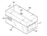
Translated fromKorean도 1 은 본 발명의 제1실시예에 따른 리프레쉬 장치의 보관시 상태를 나타낸 사시도1 is a perspective view showing a state of storage of the refresh apparatus according to the first embodiment of the present invention
도 2 는 도 1의 Ⅰ-Ⅰ선 단면도2 is a cross-sectional view taken along line II of FIG. 1.
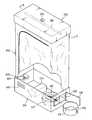
도 3 은 본 발명의 제1실시예에 따른 리프레쉬 장치의 사용시 상태를 나타낸 사시도3 is a perspective view showing a state in use of the refresh apparatus according to the first embodiment of the present invention;
도 4 는 도 3의 Ⅱ-Ⅱ선 단면도4 is a cross-sectional view taken along the line II-II of FIG. 3.
도 5 는 도 1의 배면도5 is a rear view of FIG.
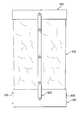
도 6 은 도 3의 배면도6 is a rear view of FIG. 3.
도 7 은 본 발명의 제1실시예에 따른 리프레쉬 장치가 세탁 장치와 연동되게 사용되는 상태를 개략적으로 나타낸 구성도7 is a configuration diagram schematically showing a state in which the refresh apparatus according to the first embodiment of the present invention is used in conjunction with a laundry apparatus;
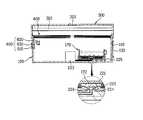
도 8 은 본 발명의 제2실시예에 따른 리프레쉬 장치의 스팀 생성부 구조를 설명하기 위한 요부 단면도8 is a cross-sectional view illustrating main parts of a structure of a steam generator of a refreshing apparatus according to a second exemplary embodiment of the present invention.
도면의 주요부분에 대한 부호의 설명Explanation of symbols for main parts of the drawings
100. 베이스부110. 장착구100.
130. 개폐 도어140. 조작 패널130. Opening and closing door 140. Operation panel
170. 물저장부171. 열전도판170.
172. 돌출부211,225. 안착부172.Protrusions 211,225. Seating part
212,222. 전열코일213,223. 컨트롤러212,222. Electric coil 213,223. controller
224. 전원연결단자300. 커버부224.
310. 홀더바320. 배출구310. Holder
400. 바디부500. 서포터부400.
600. 스팀 공급부610. 관로 연결구600.
620. 개폐 도어630. 판독부620. Opening and closing door 630. Reader
221. 열전도판10. 세탁 장치221.
20. 스팀 생성부30. 스팀 유로관20.
본 발명은 의류용 장치에 관한 것으로서, 더욱 상세하게는 의류 등의 주름을 제거함과 더불어 살균 효과를 얻을 수 있도록 구성된 새로운 형태의 의류용 리프레쉬 장치에 관한 것이다.The present invention relates to a device for clothes, and more particularly, to a new type of clothes refreshing device configured to remove wrinkles, such as clothes and to obtain a sterilization effect.
일반적으로 의류용 장치라 함은 의류에 관련된 각종 작업을 수행하는 기기로써 의류를 세탁하는 세탁기와, 젖은 의류를 건조하는 건조기 등 많은 기기 등이 포함된다.In general, the apparatus for clothes is a device that performs various operations related to clothes, and includes many machines such as a washing machine for washing clothes and a dryer for drying wet clothes.
상기한 각종 의류용 장치 중 건조기는 세탁물이 일괄적으로 투입된 상태로 건조 과정이 진행되기 때문에 엉켜진 부위에 대한 원활한 건조가 이루어지지 못한 다는 문제점이 있었다.The dryer of the various apparel devices described above has a problem that the drying process is not performed smoothly because the drying process is performed in a state in which laundry is put in a batch.
뿐만 아니라, 종래의 건조기는 그 내부에서 장시간 보존될 경우 주름이 심화되어 반드시 다림질이 필요시되었던 불편함을 가지며, 의류 등의 보관이 불가능하였다.In addition, the conventional dryer has the inconvenience that the wrinkles were required to be ironed deeply when deeply stored in the inside for a long time, and storage of clothes and the like was impossible.
이에 최근에는 건조 용량을 확대하고, 장시간의 보관도 가능하도록 한 새로운 건조 장치에 대한 요구가 이루어졌으며, 미국특허출원공개 US2004/0194339 A1 및 US2004/0154194 A1과 같이 드럼식 건조기에 별도의 건조 캐비넷을 더 구비된 혼합식 건조기가 제공되고 있다.In recent years, there has been a demand for a new drying device that can extend the drying capacity and allow for long-term storage, and additional drying cabinets have been added to drum dryers such as US Patent Application Publications US2004 / 0194339 A1 and US2004 / 0154194 A1. A combined dryer provided is provided.
상기와 같은 혼합식 건조기는 회전되는 드럼을 가지는 일반적인 드럼식 건조기의 상측에 각종 세탁물의 수납 공간을 가지면서 열풍을 공급받는 건조 캐비넷이 장착되어 이루어진 건조 기기이다.Mixing dryer as described above is a drying device is equipped with a drying cabinet receiving hot air while having a storage space for various laundry on the upper side of the general drum type dryer having a rotating drum.
이 때, 상기 건조 캐비넷은 상기 드럼식 건조기로부터 열풍을 공급받아 그 내부에 수납되는 의류 등을 건조시키거나 장시간 보관하는데 사용된다.At this time, the drying cabinet is used to dry or store for a long time the clothes received in the hot air from the drum dryer.
하지만, 전술한 건조 캐비넷은 반드시 상기 드럼식 건조기와 일체로 구성되어야만 그 동작이 가능하다는 문제점을 가진다.However, the above-described drying cabinet has a problem that its operation is possible only if it is configured integrally with the drum dryer.
이는, 상기 건조 캐비넷이 드럼식 건조기와 결합되어 있어야만 고온의 열풍을 공급받을 수 있기 때문이다.This is because the drying cabinet can be supplied with hot air only when it is combined with a drum type dryer.
이로 인해, 상기 건조 캐비넷은 상기 드럼식 건조기와 독립적으로 사용되지 못하고 항상 혼합식 건조기의 전체 전원이 인가된 상태에서 상기 건조 캐비넷에 대한 제어가 이루어질 수 밖에 없었다.For this reason, the drying cabinet cannot be used independently of the drum type dryer, and control of the drying cabinet is inevitably performed in a state where the power of the mixed dryer is always applied.
또한, 전술한 혼합식 건조기의 건조 캐비넷은 의류에 대한 주름 제거와 살균 등을 위한 리프레쉬 운전이 별도로 존재하지 않았기 때문에 단시간의 의류 보관에는 부적합하다는 문제점을 가진다.In addition, the drying cabinet of the above-described mixed dryer has a problem that it is unsuitable for storing clothes for a short time because there is no refresh operation for removing wrinkles and sterilization of clothes.
본 발명은 상기한 종래 기술에 대한 문제점을 해결하기 위해 안출한 것으로서, 본 발명의 목적은 의류에 대한 단시간의 보관이 가능함과 더불어 그 보관시 해당 의류의 주름 제거와 살균 등의 리프레쉬 운전이 가능하고, 독립적으로 사용될 수 있음과 더불어 자유로운 설치 및 휴대가 가능하도록 한 새로운 구조의 리프레쉬 장치가 구비된 세탁 장치를 제공하고자 한 것이다.The present invention has been made to solve the above problems of the prior art, the object of the present invention is to be able to store a short time for the clothing and at the same time during the storage of the wrinkle removal and sterilization of the garment can be refreshing operation Another object of the present invention is to provide a laundry machine equipped with a refreshing device having a new structure that can be used independently and that can be freely installed and carried.
특히, 본 발명은 전술한 리프레쉬 운전을 위한 장치가 세탁기나 의류 건조기 등의 세탁 장치와도 호완이 가능할 뿐 아니라, 공용으로 연동되어 사용할 수 있도록 한 구조가 적용된 새로운 구조의 리프레쉬 장치가 구비된 세탁 장치를 제공하고자 한 것이다.In particular, the present invention not only can the device for the refresh operation described above can be compatible with the washing device such as a washing machine or a clothes dryer, but also has a washing device having a refresh structure of a new structure to which the structure is applied so that it can be used in common. It is intended to provide.
상기 목적을 달성하기 위한 본 발명의 형태는 소정의 공간을 가지도록 형성된 베이스부; 상기 베이스부 내에 장착되며, 스팀 생성에 필요한 물이 저장되는 소정의 저장 공간을 가지는 물저장부; 상기 물저장부 내에 저장된 물을 가열시켜 증발시키는 스팀 생성부; 상기 베이스부의 상면에 결합되어 상기 베이스부의 상면을 커버하는 커버부; 상기 베이스부와 상기 커버 사이에 접힘 혹은, 펼쳐짐이 가능하게 구비되며, 리프레쉬 운전을 위한 소정의 공간을 형성하는 바디부; 그리고, 상기 베이스부와 상기 커버부 중 적어도 어느 한 부위에 구비되어 외부로부터 스팀을 제공받는 스팀 공급부:를 포함하여 구성됨을 특징으로 하는 리프레쉬 장치가 제공된다.Embodiment of the present invention for achieving the above object is a base portion formed to have a predetermined space; A water storage unit mounted in the base unit and having a predetermined storage space in which water required for steam generation is stored; A steam generator for heating and evaporating water stored in the water storage unit; A cover part coupled to an upper surface of the base part to cover an upper surface of the base part; A body part which is provided between the base part and the cover so as to be folded or unfolded and forms a predetermined space for a refresh operation; And, at least one of the base portion and the cover portion is provided with a steam supply unit: provided with steam from the outside is provided with a refreshing device comprising a.
이하, 전술한 본 발명의 리프레쉬 장치에 따른 바람직한 실시예를 도시한 도 1 내지 도 8을 참조하여 보다 구체적으로 설명하면 다음과 같다.Hereinafter, with reference to Figures 1 to 8 showing a preferred embodiment according to the refresh apparatus of the present invention described above in detail.
우선, 첨부된 도 1 내지 도 4와 같이 본 발명의 바람직한 제1실시예에 따른 리프레쉬 장치는 크게 베이스부(100)와, 물저장부(170)와, 스팀 생성부와, 커버부(300)와, 바디부(400)를 포함하여 구성된다.First, as shown in FIGS. 1 to 4, the refreshing apparatus according to the first preferred embodiment of the present invention includes a
여기서, 상기 베이스부(100)는 본 발명의 실시예에 따른 리프레쉬 장치의 몸체를 형성하면서 스팀 생성을 위한 소정량의 물이 저장되는 공간을 가지도록 형성된다.Here, the
특히, 상기 베이스부(100)에는 상기 물저장부(170)를 외부로부터 장착할 수 있도록 장착구(110)가 더 형성됨이 바람직하다.In particular, the
이 때, 상기 장착구(110)의 형성 위치는 상기 베이스부(100)의 측면에 형성됨이 바람직하다. 물론, 상기 장착구(110)의 형성 위치는 상기 베이스부(100)의 정면에 형성될 수도 있다.At this time, the mounting position of the mounting
뿐만 아니라, 상기 장착구(110)에는 그 선택적인 개폐를 위한 개폐 도어(130)가 더 구비됨이 바람직하다.In addition, the mounting
그리고, 리프레쉬 장치를 구성하는 물저장부(170)는 상기 베이스부(100) 내에 장착되며, 스팀 생성에 필요한 물이 저장되는 소정의 저장 공간을 가지도록 형성된다.In addition, the
이 때, 상기 물저장부(170)는 그 상면이 개구된 상태로 물의 투입 및 스팀의 발산이 가능한 통 형상으로 형성된다.At this time, the
또한, 상기 물저장부(170)의 내벽면 중 베이스부(100)에 장착되는 하단측 내벽면에는 열전도판(171)이 구비된다.In addition, a
상기한 열전도판(171)은 높은 열전도율을 가지는 재질로 형성됨이 바람직하다. 상기 열전도판(171)의 역할은 후술하는 스팀 생성부로부터 제공받은 고온의 열을 상기 물저장부(170) 내의 전 부위로 빠르게 전도하도록 한다.The thermal
물론, 상기 열전도판(171)은 상기 물저장부(170)의 내벽면 전체에 구비됨이 바람직하지만 제조단가의 상승 등을 고려할 때 상기 베이스부(100)에 장착되는 측의 내벽면 즉, 저면에만 장착하더라도 충분한 열전도 효과를 얻을 수 있다.Of course, the
특히, 상기 열전도판(171)은 첨부된 도 2 및 도 4와 같이 상기 물저장부(170)의 저면 자체를 이루도록 함이 가장 바람직하다.In particular, the
그리고, 리프레쉬 장치를 구성하는 스팀 생성부는 상기 물저장부(170) 내에 저장된 물을 가열시켜 상기 물을 증발시키는 역할을 수행하도록 구성되며, 크게 안착부(211)와, 전열코일(212)과 컨트롤러(213)를 포함하여 구성된다.In addition, the steam generating unit constituting the refreshing device is configured to heat the water stored in the
이 때, 상기 안착부(211)는 상기 베이스부(100)의 내벽면에 구비되어 상기 물저장부(170)가 안착 위치를 결정하는 부위이다.At this time, the
또한, 상기 전열코일(212)은 상기 베이스부(100)의 내부 중 상기 물저장부(170)의 저면이 장착되는 부위 즉, 상기 안착부의 내부를 따라 구비되며, 상기 열 전도판(171)으로 고온의 열을 제공하는 역할을 수행한다.In addition, the
이 때, 상기 전열코일(212)과 상기 열전도판(171)은 비록 도시되지는 않았지만 적어도 어느 한 부위가 서로 접촉되도록 구성하여 원활한 열전달이 가능하도록 함이 바람직하다.At this time, the
또한, 상기 컨트롤러(213)는 상기 베이스부(100)의 내부 공간상에 구비되며, 상기 전열코일(212)의 발열 제어를 수행하도록 구성된다.In addition, the
이 때, 베이스부(100)의 전면에는 상기 컨트롤러(213)의 제어를 위한 조작 패널(140)이 구비됨이 바람직하다.At this time, it is preferable that an
전술한 스팀 생성부는 물저장부(170) 내에 저장된 물의 수위가 최저 수위 이하로 낮아질 경우 과도 발열로 인한 화재의 위험을 가진다.The steam generator described above has a risk of fire due to overheating when the water level of the water stored in the
이에 따라, 상기 스팀 생성부 혹은, 베이스부(100) 내측에는 비록 도시하지는 않았지만 상기 물이 항상 일정 수위 이하로 낮아지지 않도록 온도센서나 습도센서 혹은, 수위센서 중 적어도 어느 하나가 더 구비됨이 바람직하다.Accordingly, although not shown, at least one of a temperature sensor, a humidity sensor, or a water level sensor may be further provided inside the steam generator or the
그리고, 리프레쉬 장치를 구성하는 커버부(300)는 상기 베이스부(100)의 상면을 폐쇄하는 역할을 수행하며, 그 내부 역시 소정의 공간을 가지도록 형성됨이 바람직하다.In addition, the
이 때, 상기 커버부(300) 내의 공간 상에는 옷걸이를 걸기위한 홀더바(310)가 더 구비되며, 상기 홀더바(310)는 그 양단이 상기 커버부(300)의 서로 대향되는 두 단변측 면에 각각 연결된다.In this case, a
물론, 상기 홀더바(310)는 그 양단이 상기 커버부(300)의 서로 대향되는 두 장변측 면에 각각 연결할 수도 있다.Of course, both ends of the
또한, 상기 커버부(300)에는 그 내부에 존재하는 공기 혹은, 스팀의 일부가 배출될 수 있도록 배출구(320)를 더 형성함이 바람직하다.In addition, the
이 때, 상기 배출구(320)는 단순한 구멍으로 형성될 수도 있지만, 그 개도량의 조절이 가능하도록 구성됨이 보다 바람직하다.At this time, the
그리고, 리프레쉬 장치를 구성하는 바디부(400)는 상기 베이스부(100)와 상기 커버부(300) 사이에 연결되고, 접힘이 가능한 유연한 재질로 형성된다.The
특히, 상기한 바디부(400)는 그 펼쳐짐이 이루어질 경우 리프레쉬 운전을 위한 의류가 수납되는 소정의 수납 공간을 형성하도록 구성되며, 그 면상에는 상기 수납 공간의 선택적인 개방이 가능하도록 형성된다.In particular, the
이 때, 상기 바디부(400)의 수납 공간을 개폐하기 위한 구조는 지퍼(Zipper) 구조로 이루어짐이 바람직하다.At this time, the structure for opening and closing the storage space of the
상기 수납 공간의 개폐를 위한 구조는 상기 수납 공간 내에 존재하는 스팀이 외부로 배출됨을 차단할 수 있도록 하기 위한 것이다.The structure for opening and closing the storage space is to block the steam existing in the storage space to be discharged to the outside.
물론, 상기 수납 공간을 개방하기 위한 구조는 다양한 형태로도 이루어질 수 있다.Of course, the structure for opening the storage space may be made in various forms.
그리고, 리프레쉬 장치를 구성하는 스팀 공급부(600)는 상기 베이스부(100)와 상기 커버부(300) 중 적어도 어느 한 부위에 구비되어 외부로부터 스팀을 제공받을 수 있도록 형성된다.In addition, the
이 때, 상기 스팀 공급부(600)는 스팀이 유동되는 관로의 착탈이 가능한 관로 연결구(610)와, 상기 관로 연결구(610)를 개폐하는 개폐도어(620)를 포함하여 구성된다.At this time, the
상기 관로 연결구(610)는 통상적인 호스 등의 연결을 위해 사용되는 구조로 형성됨이 바람직하다.The
또한, 상기 개폐도어(620)는 상기 리프레쉬 장치를 그 독립적으로 사용할 경우 상기 관로 연결구(610)가 폐쇄된 상태를 이룰 수 있도록 함으로써 스팀의 누설이 방지되도록 하는 역할을 수행한다.In addition, the opening and closing
전술한 스팀 공급부(600)는 베이스부(100)의 둘레면 상에 구비됨을 그 실시예로 제시하고 있지만, 상기 커버부(300)의 둘레면 혹은, 상면에 구비될 수도 있다.The
특히, 상기 스팀 공급부(600)에는 상기 스팀이 유동되는 관로의 착탈 여부에 대한 판독을 수행하는 판독부(630)가 더 구비됨이 바람직하다.In particular, the
만일, 상기 판독부(630)에 의해 판독된 결과가 상기 관로의 연결이 이루어졌음으로 확인될 경우 상기 스팀 생성부(200)의 동작 제어가 이루어지지 않도록 제어됨이 바람직하다.If the result read by the
이 때, 상기 판독부(630)는 리미트 스위치 혹은, 근접 센서 등 다양한 구조로 구성될 수 있다.In this case, the
물론, 필요에 따라서는 상기 스팀 공급부(600)를 통해 외부로부터 스팀이 공급되더라도 상기 리프레쉬 장치에 구비된 스팀 생성부(200)가 동작되도록 제어될 수도 있다.Of course, if necessary, even if steam is supplied from the outside through the
한편, 전술한 본 발명의 제1실시예에 따른 리프레쉬 장치에는 첨부된 도 3과 같이 상기 바디부(400)가 펼쳐졌을 경우 그 펼쳐진 상태를 유지하도록 지지하는 역할을 수행하는 서포터부(500)를 더 구비함이 바람직하다.On the other hand, the refreshing device according to the first embodiment of the present invention described above, when the
이 때, 상기 서포터부(500)는 그 양단이 상기 베이스부(100)와 상기 커버부(300)의 후면에 각각 연결되면서 링크(link) 형태로 접었다 펴는 동작이 가능하게 구성됨이 바람직하다. 물론 도시하지는 않았지만 상기 서포터부(500)는 텔레스코픽(telescopic) 형태로 그 길이를 늘였다 줄이는 동작을 수행하도록 구성될 수도 있다.At this time, the
이하, 전술한 일련의 구조로 이루어진 본 발명의 제1실시예에 따른 리프레쉬 장치의 동작 과정 중 상기 리프레쉬 장치를 독립적으로 사용하는 경우 및 여타의 세탁 장치와 연동시켜 사용하는 경우에 대하여 각각 설명하면 아래와 같다.Hereinafter, a case in which the refresh apparatus is used independently and a case in which it is used in conjunction with other laundry apparatuses during the operation of the refresh apparatus according to the first embodiment of the present invention having the above-described series of structures will be described below. same.
먼저, 본 발명의 제1실시예에 따른 리프레쉬 장치를 독립적으로 사용하는 경우에는 후술하는 일련의 과정과 같이 그 동작이 이루어진다.First, when the refresh apparatus according to the first embodiment of the present invention is used independently, the operation is performed as in the following series of procedures.
즉, 최초 상태는 첨부된 도 1 및 도 2와 같이 커버부(300)가 베이스부(100)의 상면을 폐쇄하고 있는 상태이다.That is, the initial state is a state in which the
이의 경우, 바디부(400)는 상기 커버부(300)와 상기 베이스부(100) 내에 접혀진 상태로 숨겨지고, 서포터부(500)는 첨부된 도 5와 같이 접혀진 상태이다.In this case, the
그리고, 상기한 상태에서 의류의 리프레쉬를 수행하고자 한다면 상기 커버부(300)를 상기 베이스부(100)로부터 개방시킨다.In addition, if it is desired to refresh the garment in the above state, the
이의 경우, 상기 바디부(400)는 상기 커버부(300)와 상기 베이스부(100) 사 이로부터 외부로 노출됨과 더불어 점차 펼쳐지게 된다.In this case, the
이 때, 첨부된 도 3 및 도 4는 상기 바디부(400)가 완전히 펼쳐진 상태가 도시되고 있다.At this time, Figures 3 and 4 attached to the
또한, 상기 바디부(400)가 완전히 펼쳐지게 되면 첨부된 도 6과 같이 서포터부(500)에 의해 상기 바디부(400)는 펼쳐진 상태로 유지된다.In addition, when the
그리고, 상기 바디부(400)가 완전히 펼쳐지게 되면 지퍼를 조작하여 그 내부 공간을 개방한다.Then, when the
이와 함께, 사용자는 리프레쉬하고자 하는 의류를 옷걸이에 건 후 상기 옷걸이를 커버부(300) 내의 홀더바(310)에 걸고 다시 지퍼를 조작하여 그 내부 공간을 폐쇄한다.In addition, the user hangs the clothes to be refreshed on a hanger, hangs the hanger on the
따라서, 상기 의류는 바디부(400) 내에 수납된 상태를 이루게 된다.Thus, the garment is in a state accommodated in the
그리고, 전술한 일련의 과정이 완료되어 리프레쉬 운전을 수행하고자 한다면 스팀 생성부를 이루는 컨트롤러(213)를 조작하면 된다.In addition, when the above-described series of processes are completed and the refresh operation is to be performed, the
이 때, 상기 리프레쉬 운전의 수행전에는 물저장부(170)에 스팀 생성을 위한 물이 저장되어 있어야 한다.At this time, before performing the refresh operation, water for steam generation should be stored in the
이는, 베이스부(100)의 장착구(110)에 구비된 개폐 도어(130)를 개방한 상태에서 물저장부(170)를 취출한 후 상기 물저장부(170) 내에 물을 저장시키고, 계속해서 상기 물저장부(170)를 상기 장착구(110)를 통해 베이스부(100) 내에 구비된 안착부(211)에 장착하면 된다.This, after taking out the
그리고, 전술한 컨트롤러(213)의 조작이 이루어진다면 전열코일(212)의 발열 이 이루어지게 되고, 상기 전열코일(212)의 발열로 인해 발생된 고온의 열은 상기 물저장부(170)의 열전도판(171)으로 전달된다.In addition, when the above-described operation of the
따라서, 상기 물저장부(170) 내에 저장된 물은 가열되면서 증발되고, 이러한 증발로 인해 스팀의 생성이 이루어진다.Therefore, the water stored in the
그리고, 상기와 같이 생성된 스팀은 상기 베이스부(100)의 내부 공간으로부터 상승하면서 바디부(400) 내로 제공되고, 계속해서 상기 바디부(400) 내에 위치된 의류로 제공된다.And, the steam generated as described above is provided into the
이에 따라, 상기 의류는 상기 고온의 스팀에 의해 살균이 이루어짐과 더불어 주름 등이 제거되면서 결과적으로 리프레쉬가 이루어진다.Accordingly, the garment is sterilized by the high temperature steam and wrinkles are removed, resulting in a refresh.
특히, 상기 의류가 수납되는 공간인 바디부(400) 내의 공간은 협소하기 때문에 빠른 시간 내에 해당 의류의 리프레쉬가 이루어질 수 있게 되고, 이로 인해 단시간 보관하더라도 원활한 의류의 리프레쉬가 가능하다는 장점을 가지게 된다.In particular, since the space in the
전술한 일련의 과정이 진행되는 도중 리프레쉬 운전이 완료되었음에도 불구하고 바디부(400) 내에 스팀이 가득차있게 되면 상기 스팀으로 인해 의류가 젖게 될 수도 있다.Even though the refresh operation is completed during the above-described series of processes, if the steam in the
이에 따라, 상기 리프레쉬 운전이 완료될 경우 커버부(300)에 형성된 배출구(320)가 개방되도록 조작함이 바람직하다.Accordingly, when the refresh operation is completed, it is preferable to manipulate the
물론, 바디부(400)의 지퍼를 개방함으로써 그 내부의 스팀을 완전 배출시킬 수도 있다.Of course, by opening the zipper of the
한편, 본 발명의 제1실시예에 따른 리프레쉬 장치가 첨부된 도 7과 같이 세 탁 장치(예컨대, 세탁기나 의류 건조기 등)(10) 등에 연동되어 사용될 경우에는 후술하는 일련의 과정과 같이 그 동작이 이루어진다.On the other hand, when the refreshing device according to the first embodiment of the present invention is used in conjunction with the washing device (eg, washing machine, clothes dryer, etc.) 10, as shown in FIG. This is done.
이 때, 상기 세탁 장치(10)에는 상기 리프레쉬 장치와는 별도로 스팀을 생성하도록 구성된 스팀 생성부(20)가 구비되며, 상기 스팀 생성부(20)에는 스팀 유로관(30)이 연결된다. 상기 스팀 유로관(20)은 상기 세탁 장치의 외부로 선택적인 인출 가능하게 구성됨이 바람직하다.At this time, the
이의 상태에서, 사용자가 상기 세탁 장치(10)에 구비된 스팀 생성부(20)를 이용하여 리프레쉬 장치 내에 수납된 각종 의류의 리프레쉬를 위한 운전을 수행하고자 한다면 상기 리프레쉬 장치의 관로 연결구(610)를 폐쇄하고 있는 개폐도어(620)를 조작하여 상기 관로 연결구(610)를 개방시킨다.In this state, if the user wants to perform the operation for the refresh of the various clothes stored in the refreshing apparatus using the
그리고, 상기 개방된 관로 연결구(610)에 상기 스팀 유로관(30)을 결합시킨다.Then, the steam
이의 경우, 상기 관로 연결구(610)에 구비된 판독부(630)는 상기 스팀 유로관(30)의 결합을 인지하게 되고, 이의 정보를 상기 리프레쉬 장치의 컨트롤러(213)로 제공하여 상기 리프레쉬 장치에 구비된 스팀 생성부의 동작 즉, 전열코일(212)의 발열은 이루어지지 않도록 제어한다.In this case, the
이 때, 상기 리프레쉬 장치를 이루는 커버부(300)의 개방과 바디부(400) 내에 각종 의류를 수납시키는 일련의 조작은 전술한 상기 리프레쉬 장치의 독립적인 운전시의 경우와 동일하게 진행된다.At this time, the opening of the
그리고, 상기한 상태에서 세탁 장치(10)의 스팀 생성부(20)를 동작시키게 되 면 상기 스팀 생성부(20)로부터 스팀의 생성이 이루어지며, 상기와 같이 생성된 스팀은 스팀 유로관(30)을 통해 상기 리프레쉬 장치의 베이스부(100) 내부 공간으로 전달된다.When the
계속해서, 상기 전달된 스팀은 상기 리프레쉬 장치의 바디부(400) 내부를 향해 상승하면서 상기 바디부(400) 내에 위치된 의류로 제공된다.Subsequently, the delivered steam is provided to the garment located in the
이에 따라, 상기 의류는 상기 고온의 스팀에 의해 살균이 이루어짐과 더불어 주름 등이 제거되면서 결과적으로 상기 의류의 리프레쉬가 이루어진다.Accordingly, the garment is sterilized by the high temperature steam and wrinkles are removed, and as a result, the garment is refreshed.
한편, 전술한 바와 같이 세탁 장치(10) 등에 적용하여 사용하는 형태의 리프레쉬 장치에는 스팀 생성부가 구비되지 않을 수도 있다. 하지만, 상기 리프레쉬 장치는 독립적인 사용이 가능함과 동시에 상기 세탁 장치(10)에 적용될 수도 있도록 공용으로 사용되기 위해서는 상기 리프레쉬 장치에 스팀 생성부가 함께 구비되어야만 가장 바람직하다.On the other hand, as described above, the steam generating unit may not be provided in the refresh apparatus of the type applied to the
뿐만 아니라, 세탁 장치(10)의 스팀 생성부(20)에 연결된 스팀 유로관(30)의 타단이 연결되는 위치는 리프레쉬 장치의 베이스부(100)가 아닌 커버부(300)에 연통되도록 구성될 수도 있다.In addition, the position at which the other end of the
한편, 전술한 바와 같은 본 발명의 제1실시예에 따른 리프레쉬 장치 중 스팀 생성부는 전열코일(212)의 발열에 의해 발생된 고온의 물저장부(170) 내에 구비된 열전도판(171)으로 전달될 때 서로간 즉, 상기 열전도판(171)(혹은, 물저장부의 저면)과 상기 전열코일(212)이 장착된 면 간이 정확히 밀착되지 않을 경우 원활한 열전도가 어려운 문제점이 야기된다.Meanwhile, the steam generator of the refreshing apparatus according to the first embodiment of the present invention as described above is transferred to the
따라서, 상기 문제점이 방지될 수 있도록 본 발명의 제2실시예에서는 상기 스팀 생성부를 이루는 열전도판과 전열코일이 직접 접촉되도록 구성함을 제시한다.Therefore, in order to prevent the above problem, the second embodiment of the present invention suggests that the heat conduction plate constituting the steam generator and the heat transfer coil are directly contacted.
첨부된 도 8은 상기한 본 발명의 제2실시예에 따른 스팀 생성부의 구조를 설명하기 위한 요부 단면도이다.8 is a cross-sectional view illustrating main parts of the structure of the steam generator according to the second embodiment of the present invention.
이를 통해 알 수 있듯이 본 발명의 제2실시예에 따른 리프레쉬 장치의 스팀 생성부는 크게 열전도판(221)과, 전열코일(222)과, 전원연결단자(224)와, 컨트롤러(223)를 포함하여 구성됨을 제시한다.As can be seen through this, the steam generator of the refreshing apparatus according to the second embodiment of the present invention includes a
여기서, 상기 열전도판(221)은 상기 물저장부(170)의 내벽면 중 상기 베이스부(100)에 장착되는 측의 내측 벽면을 따라 구비된다.Here, the
또한, 상기 전열코일(222)은 상기 열전도판(221)의 저부에 구비된다.In addition, the
이 때, 상기 전열코일(222)은 상기 물저장부(170)의 저면과 상기 열전도판(221) 사이의 공간에 구비됨이 바람직하며, 특히 상기 열전도판(221)의 저면을 따라 밀착되도록 구비함이 바람직하다.At this time, the
이의 경우 상기 물저장부(170)의 저면은 내열성 재질로 형성되되, 열전도도가 낮은 재질로 형성됨이 바람직하다. 이는, 상기 물저장부(170)의 저면이 과열됨에 따른 주위의 회로부품이 파손되는 등의 문제점을 미연에 방지하기 위함이다.In this case, the bottom surface of the
이와 함께, 상기 물저장부(170)의 저면 중앙측 부위는 상부를 향해 소정 높이만큼 돌출된 돌출부(172)가 형성되고, 상기 돌출부(172)의 내주면을 따라 상기 전열코일(222)의 단자가 노출되도록 형성된다.In addition, the bottom portion of the bottom portion of the
또한, 상기 전원연결단자(224)는 상기 베이스부(100)의 내부 중 상기 물저장 부(170)의 돌출부(172) 내측에 수용되면서 상기 전열코일(222)의 단자와 접촉되도록 돌출 형성된다.In addition, the
이 때, 상기 전원연결단자(224)는 상기 전열코일(222)로 전원을 제공하는 역할을 수행한다.At this time, the
또한, 상기 컨트롤러(223)는 베이스부(100)의 내부 공간상에 구비되며, 상기 전원연결단자(224)로 선택적인 전원 공급을 수행하도록 구성된다.In addition, the
물론, 상기한 스팀 생성부에는 전술한 본 발명의 제1실시예와 같은 안착부(225)가 더 포함되어 구성됨이 바람직하며, 상기 안착부(225)는 상기 베이스부(100)의 내벽면에 구비되어 상기 물저장부(170)가 안착 위치를 결정하게 된다.Of course, the steam generating unit is preferably configured to further include a
따라서, 내부에 물이 저장된 물저장부(170)를 안착부(225)에 장착하게 되면, 전열코일(222)과 상기 전원연결단자(224) 간의 접촉이 이루어지면서 상기 전열코일(222)은 전원 공급이 가능한 상태를 이루게 되고, 이의 생태에서 리프레쉬 운전을 위한 컨트롤러(223)의 조작이 이루어진다면 상기 전열코일(222)은 상기 공급된 전원에 의해 발열된다.Therefore, when the
이 때, 상기 전열코일(222)의 발열로 인해 발생된 고온의 열은 그 상면에 밀착된 열전도판(221)으로 전달됨으로써 상기 물저장부(170) 내에 저장된 물은 가열되면서 증발되고, 이러한 증발로 인해 스팀의 생성이 이루어진다.At this time, the high temperature heat generated by the heat generation of the
그리고, 상기와 같이 생성된 스팀은 상기 베이스부(100)의 내부 공간으로부터 상승하면서 바디부(400) 내로 제공되고, 계속해서 상기 바디부(400) 내에 위치된 의류로 제공된다.And, the steam generated as described above is provided into the
이에 따라, 상기 의류는 상기 고온의 스팀에 의해 살균이 이루어짐과 더불어 주름 등이 제거되면서 결과적으로 의류의 리프레쉬가 이루어진다.Accordingly, the garment is sterilized by the high temperature steam and wrinkles are removed, and as a result, the garment is refreshed.
물론, 상기 리프레쉬 장치가 세탁 장치 등에 연동되어 사용될 경우에는 전술한 본 발명의 제1실시예에 따른 세탁 장치와의 연동 과정과 동일한 과정으로 의류의 리프레쉬 운전이 진행된다.Of course, when the refresh apparatus is used in conjunction with a washing apparatus or the like, the refresh operation of the garment is performed in the same process as the interlocking process with the washing apparatus according to the first embodiment of the present invention described above.
이상에서 설명된 바와 같이, 본 발명에 따른 리프레쉬 장치는 의류에 대한 단시간의 보관이 가능함과 더불어 그 보관시 해당 의류의 주름 제거와 살균 등의 리프레쉬가 가능하여 사용자의 만족도를 향상시킬 수 있다는 효과를 가진다.As described above, the refreshing device according to the present invention is capable of storing the clothes for a short time and refreshing the wrinkles and sterilization of the clothes during the storage, thereby improving the user's satisfaction. Have
특히, 본 발명은 상기한 리프레쉬 장치는 기존의 드럼식 건조기 혹은, 별도의 건조 장치와는 독립적으로 제어되면서 사용할 수 있으며, 의류의 리프레쉬만을 전문적으로 수행하기 때문에 사용자의 만족도가 향상될 수 있다는 효과를 가진다.In particular, the present invention can be used while the refreshing device is controlled independently of the existing drum dryer or a separate drying device, and has the effect that the user's satisfaction can be improved because only the refresh of the clothing is performed professionally. .
Claims (7)
Translated fromKoreanPriority Applications (3)
| Application Number | Priority Date | Filing Date | Title |
|---|---|---|---|
| KR1020050019105AKR100891660B1 (en) | 2005-03-08 | 2005-03-08 | Refresh device |
| US11/628,193US20080256989A1 (en) | 2005-02-08 | 2006-02-28 | Refresher and Machine for Washing or Drying with the Same |
| PCT/KR2006/000696WO2006091057A1 (en) | 2005-02-28 | 2006-02-28 | Refresher and machine for washing or drying with the same |
Applications Claiming Priority (1)
| Application Number | Priority Date | Filing Date | Title |
|---|---|---|---|
| KR1020050019105AKR100891660B1 (en) | 2005-03-08 | 2005-03-08 | Refresh device |
Publications (2)
| Publication Number | Publication Date |
|---|---|
| KR20060098801A KR20060098801A (en) | 2006-09-19 |
| KR100891660B1true KR100891660B1 (en) | 2009-04-02 |
Family
ID=37630165
Family Applications (1)
| Application Number | Title | Priority Date | Filing Date |
|---|---|---|---|
| KR1020050019105AExpired - Fee RelatedKR100891660B1 (en) | 2005-02-08 | 2005-03-08 | Refresh device |
Country Status (1)
| Country | Link |
|---|---|
| KR (1) | KR100891660B1 (en) |
Citations (4)
| Publication number | Priority date | Publication date | Assignee | Title |
|---|---|---|---|---|
| JPS56139499U (en) | 1980-03-22 | 1981-10-21 | ||
| KR19990083368A (en)* | 1998-04-27 | 1999-11-25 | 다니엘에프.호프 | Clothes treating apparatus |
| KR20010113436A (en)* | 2000-08-16 | 2001-12-28 | 김점화 | Steam ironing apparatus |
| KR20060095406A (en)* | 2005-02-28 | 2006-08-31 | 엘지전자 주식회사 | Laundry device |
- 2005
- 2005-03-08KRKR1020050019105Apatent/KR100891660B1/ennot_activeExpired - Fee Related
Patent Citations (4)
| Publication number | Priority date | Publication date | Assignee | Title |
|---|---|---|---|---|
| JPS56139499U (en) | 1980-03-22 | 1981-10-21 | ||
| KR19990083368A (en)* | 1998-04-27 | 1999-11-25 | 다니엘에프.호프 | Clothes treating apparatus |
| KR20010113436A (en)* | 2000-08-16 | 2001-12-28 | 김점화 | Steam ironing apparatus |
| KR20060095406A (en)* | 2005-02-28 | 2006-08-31 | 엘지전자 주식회사 | Laundry device |
Also Published As
| Publication number | Publication date |
|---|---|
| KR20060098801A (en) | 2006-09-19 |
Similar Documents
| Publication | Publication Date | Title |
|---|---|---|
| KR101265602B1 (en) | laundry treating apparatus | |
| US20080256989A1 (en) | Refresher and Machine for Washing or Drying with the Same | |
| EP1936021A2 (en) | Method for controlling laundry machine | |
| KR20150009718A (en) | Laundry Treating Apparatus | |
| KR20150065297A (en) | Laundry Treating Apparatus | |
| KR100595239B1 (en) | Combined Drying Equipment with Folding Shelf | |
| US20240301617A1 (en) | Laundry treating apparatus | |
| KR100841308B1 (en) | Laundry device | |
| KR20080024864A (en) | Laundry treatment furniture | |
| KR100710221B1 (en) | Refresh device | |
| KR100845843B1 (en) | Refresh device | |
| KR100891660B1 (en) | Refresh device | |
| KR100813049B1 (en) | Refresh device | |
| KR100891659B1 (en) | Refresh device | |
| KR100845844B1 (en) | Refresh device | |
| KR100808173B1 (en) | Refresh device | |
| KR100841307B1 (en) | Laundry device | |
| KR100880633B1 (en) | Refresh device | |
| KR100873129B1 (en) | Laundry device | |
| KR20060095406A (en) | Laundry device | |
| KR20100007342A (en) | Cloth treating apparatus | |
| KR20220096562A (en) | Clothes Treatment Apparatus and Controlling Method Thereof | |
| KR100808177B1 (en) | Refresh device | |
| US20230118347A1 (en) | Clothing processing apparatus | |
| KR100813050B1 (en) | Refreshing device and driving control method thereof |
Legal Events
| Date | Code | Title | Description |
|---|---|---|---|
| PA0109 | Patent application | St.27 status event code:A-0-1-A10-A12-nap-PA0109 | |
| PG1501 | Laying open of application | St.27 status event code:A-1-1-Q10-Q12-nap-PG1501 | |
| A201 | Request for examination | ||
| PA0201 | Request for examination | St.27 status event code:A-1-2-D10-D11-exm-PA0201 | |
| D13-X000 | Search requested | St.27 status event code:A-1-2-D10-D13-srh-X000 | |
| D14-X000 | Search report completed | St.27 status event code:A-1-2-D10-D14-srh-X000 | |
| PN2301 | Change of applicant | St.27 status event code:A-3-3-R10-R13-asn-PN2301 St.27 status event code:A-3-3-R10-R11-asn-PN2301 | |
| E902 | Notification of reason for refusal | ||
| PE0902 | Notice of grounds for rejection | St.27 status event code:A-1-2-D10-D21-exm-PE0902 | |
| P11-X000 | Amendment of application requested | St.27 status event code:A-2-2-P10-P11-nap-X000 | |
| P13-X000 | Application amended | St.27 status event code:A-2-2-P10-P13-nap-X000 | |
| E701 | Decision to grant or registration of patent right | ||
| PE0701 | Decision of registration | St.27 status event code:A-1-2-D10-D22-exm-PE0701 | |
| GRNT | Written decision to grant | ||
| PR0701 | Registration of establishment | St.27 status event code:A-2-4-F10-F11-exm-PR0701 | |
| PR1002 | Payment of registration fee | St.27 status event code:A-2-2-U10-U11-oth-PR1002 Fee payment year number:1 | |
| PG1601 | Publication of registration | St.27 status event code:A-4-4-Q10-Q13-nap-PG1601 | |
| R18-X000 | Changes to party contact information recorded | St.27 status event code:A-5-5-R10-R18-oth-X000 | |
| R18-X000 | Changes to party contact information recorded | St.27 status event code:A-5-5-R10-R18-oth-X000 | |
| PR1001 | Payment of annual fee | St.27 status event code:A-4-4-U10-U11-oth-PR1001 Fee payment year number:4 | |
| FPAY | Annual fee payment | Payment date:20130226 Year of fee payment:5 | |
| PR1001 | Payment of annual fee | St.27 status event code:A-4-4-U10-U11-oth-PR1001 Fee payment year number:5 | |
| FPAY | Annual fee payment | Payment date:20140224 Year of fee payment:6 | |
| PR1001 | Payment of annual fee | St.27 status event code:A-4-4-U10-U11-oth-PR1001 Fee payment year number:6 | |
| FPAY | Annual fee payment | Payment date:20150224 Year of fee payment:7 | |
| PR1001 | Payment of annual fee | St.27 status event code:A-4-4-U10-U11-oth-PR1001 Fee payment year number:7 | |
| PN2301 | Change of applicant | St.27 status event code:A-5-5-R10-R13-asn-PN2301 St.27 status event code:A-5-5-R10-R11-asn-PN2301 | |
| FPAY | Annual fee payment | Payment date:20160224 Year of fee payment:8 | |
| PR1001 | Payment of annual fee | St.27 status event code:A-4-4-U10-U11-oth-PR1001 Fee payment year number:8 | |
| P22-X000 | Classification modified | St.27 status event code:A-4-4-P10-P22-nap-X000 | |
| LAPS | Lapse due to unpaid annual fee | ||
| PC1903 | Unpaid annual fee | St.27 status event code:A-4-4-U10-U13-oth-PC1903 Not in force date:20170328 Payment event data comment text:Termination Category : DEFAULT_OF_REGISTRATION_FEE | |
| PC1903 | Unpaid annual fee | St.27 status event code:N-4-6-H10-H13-oth-PC1903 Ip right cessation event data comment text:Termination Category : DEFAULT_OF_REGISTRATION_FEE Not in force date:20170328 | |
| PN2301 | Change of applicant | St.27 status event code:A-5-5-R10-R13-asn-PN2301 St.27 status event code:A-5-5-R10-R11-asn-PN2301 | |
| P22-X000 | Classification modified | St.27 status event code:A-4-4-P10-P22-nap-X000 | |
| P22-X000 | Classification modified | St.27 status event code:A-4-4-P10-P22-nap-X000 |