KR100885416B1 - Integrated accelerometer and angular accelerometer drive system - Google Patents
Integrated accelerometer and angular accelerometer drive systemDownload PDFInfo
- Publication number
- KR100885416B1 KR100885416B1KR1020070072411AKR20070072411AKR100885416B1KR 100885416 B1KR100885416 B1KR 100885416B1KR 1020070072411 AKR1020070072411 AKR 1020070072411AKR 20070072411 AKR20070072411 AKR 20070072411AKR 100885416 B1KR100885416 B1KR 100885416B1
- Authority
- KR
- South Korea
- Prior art keywords
- signal
- vibration
- axis
- angular velocity
- acceleration
- Prior art date
- Legal status (The legal status is an assumption and is not a legal conclusion. Google has not performed a legal analysis and makes no representation as to the accuracy of the status listed.)
- Expired - Fee Related
Links
Images


Classifications
- G—PHYSICS
- G01—MEASURING; TESTING
- G01P—MEASURING LINEAR OR ANGULAR SPEED, ACCELERATION, DECELERATION, OR SHOCK; INDICATING PRESENCE, ABSENCE, OR DIRECTION, OF MOVEMENT
- G01P3/00—Measuring linear or angular speed; Measuring differences of linear or angular speeds
- G01P3/42—Devices characterised by the use of electric or magnetic means
- G—PHYSICS
- G01—MEASURING; TESTING
- G01C—MEASURING DISTANCES, LEVELS OR BEARINGS; SURVEYING; NAVIGATION; GYROSCOPIC INSTRUMENTS; PHOTOGRAMMETRY OR VIDEOGRAMMETRY
- G01C19/00—Gyroscopes; Turn-sensitive devices using vibrating masses; Turn-sensitive devices without moving masses; Measuring angular rate using gyroscopic effects
- G01C19/56—Turn-sensitive devices using vibrating masses, e.g. vibratory angular rate sensors based on Coriolis forces
- G—PHYSICS
- G01—MEASURING; TESTING
- G01P—MEASURING LINEAR OR ANGULAR SPEED, ACCELERATION, DECELERATION, OR SHOCK; INDICATING PRESENCE, ABSENCE, OR DIRECTION, OF MOVEMENT
- G01P15/00—Measuring acceleration; Measuring deceleration; Measuring shock, i.e. sudden change of acceleration
- G01P15/02—Measuring acceleration; Measuring deceleration; Measuring shock, i.e. sudden change of acceleration by making use of inertia forces using solid seismic masses
- G01P15/08—Measuring acceleration; Measuring deceleration; Measuring shock, i.e. sudden change of acceleration by making use of inertia forces using solid seismic masses with conversion into electric or magnetic values
- G01P15/097—Measuring acceleration; Measuring deceleration; Measuring shock, i.e. sudden change of acceleration by making use of inertia forces using solid seismic masses with conversion into electric or magnetic values by vibratory elements
- G—PHYSICS
- G01—MEASURING; TESTING
- G01P—MEASURING LINEAR OR ANGULAR SPEED, ACCELERATION, DECELERATION, OR SHOCK; INDICATING PRESENCE, ABSENCE, OR DIRECTION, OF MOVEMENT
- G01P15/00—Measuring acceleration; Measuring deceleration; Measuring shock, i.e. sudden change of acceleration
- G01P15/14—Measuring acceleration; Measuring deceleration; Measuring shock, i.e. sudden change of acceleration by making use of gyroscopes
Landscapes
- Physics & Mathematics (AREA)
- General Physics & Mathematics (AREA)
- Engineering & Computer Science (AREA)
- Radar, Positioning & Navigation (AREA)
- Remote Sensing (AREA)
- Gyroscopes (AREA)
- Vibration Prevention Devices (AREA)
Abstract
Description
Translated fromKorean본 발명은 가속도계 및 각속도계 구동 시스템에 관한 것으로서, 더욱 상세하게는 서로 수직한 방향으로 입력되는 가속도량 및 각속도량을 측정할 수 있는 일체형 가속도계·각속도계 구동 시스템에 관한 것이다.BACKGROUND OF THE
일반적으로 관성 물리력을 측정하는 관성센서는, 가속도계와 각속도계로 대별될 수 있으며, 이는 서로 독립적인 관성센서로 개발되어 개별소자로 출시되고 있다. 이에 따라, 최근에는 관성력을 측정하거나 위치·자세 등을 계산하는 분야와 같이 가속도계와 각속도계를 동시에 사용하는 방안이 추진되고 있다.In general, an inertial sensor that measures the inertia physical force can be roughly divided into an accelerometer and an angular speedometer, which are developed as independent inertial sensors and released as individual devices. Accordingly, recently, a method of using an accelerometer and an angular speedometer simultaneously has been promoted, such as in the field of measuring inertial force or calculating position and posture.
한편, 비행체 및 잠수함과 같이 3축 관성력을 측정하기 위한 관성측정 유닛에는 각각 3개 이상의 가속도계 및 각속도계가 필요하며, 이러한 관성측정 유닛을 제작하기 위해서는 3축에 대하여 서로 수직한 방향으로 정렬하는 축간 정렬 절차를 수행하야 한다. 그러나, 이러한 축간 정렬은 관성측정 유닛의 제작단계에서 많은 비용과 시간을 소요하게 되며, 가속도계에 비해 각속도계의 수직 정렬은 상대적으로 더 복잡한 절차를 따르게 된다.Meanwhile, three or more accelerometers and angular velocities are required for inertial measurement units for measuring three-axis inertial forces, such as aircraft and submarines. The alignment procedure must be performed. However, such interaxial alignment is very costly and time consuming in the manufacturing stage of the inertial measurement unit, and the vertical alignment of the angular speedometer is relatively more complicated than the accelerometer.
이와 같이, 2축 이상의 가속도 및 각속도를 동시에 사용하는 분야에서 개별적인 가속도계와 각속도계를 사용하는 것은 그 부피 및 비용적인 측면뿐 아니라 센서 개수에 비례하는 센서 입력축간의 상호 정렬의 시간과 노력이 필요한 단점이 있었다.As such, the use of separate accelerometers and angular speedometers in the field of using two or more accelerations and angular velocities simultaneously requires not only their volume and cost but also the time and effort of mutual alignment between sensor input axes proportional to the number of sensors. There was this.
따라서, 다수의 축으로 입력되는 관성력을 측정하기 위한 복수의 가속도계와 각속도계를 사용할 경우, 단일의 기계적 구조물을 이용하여 구조적으로 상호 정렬된 센서 입력각을 구비하는 관성센서의 개발이 절실한 실정이다.Therefore, when using a plurality of accelerometers and angular accelerometers for measuring the inertial force input to a plurality of axes, the development of an inertial sensor having a sensor input angle structurally aligned using a single mechanical structure is urgently needed.
본 발명은 상기와 같은 문제점을 감안하여 안출된 것으로서, 서로 수직한 방향으로 입력되는 가속도량 및 각속도량을 측정할 수 있는 일체형 가속도계·각속도계 구동 시스템을 제공함에 그 특징적인 목적이 있다.SUMMARY OF THE INVENTION The present invention has been made in view of the above problems, and has a characteristic object of providing an integrated accelerometer and angular speed drive system capable of measuring an amount of acceleration and an angular velocity input in a direction perpendicular to each other.
본 발명은 일체형 가속도계·각속도계 구동 시스템에 관한 것으로서, 인가된 구동 전압을 이용하여 질량체(M)가 일정한 진폭을 유지하도록 하며, 가속도축 및 각속도축 방향의 진동신호를 검출하는 일체형 가속도계·각속도계; 상기 일체형 가속도계·각속도계로부터 검출된 가속도축 방향의 진동신호를 취득하는 가속도축 진동신호 취득부; 상기 가속도축 진동신호 취득부로부터 수신한 진동신호를 이용하여, 일정한 진동 폭을 갖도록 하는 가속도축 진동유지 제어신호를 출력하는 진폭유지 제어부; 상기 진폭유지 제어부로부터 인가된 전압신호를 입력받아 일체형 가속 도계·각속도계로 인가하는 가속도축 구동입력부; 상기 일체형 가속도계·각속도계로부터 검출된 각속도축 방향의 진동신호를 취득하는 각속도축 진동신호 취득부; 상기 각속도축 진동신호 취득부로부터 수신한 진동신호를 이용하여, 일정한 진동 폭을 갖도록 하는 각속도축 진동유지 제어신호를 출력하는 힘평형 제어부; 및 상기 힘평형 제어부로부터 인가된 전압신호를 입력받아 상기 일체형 가속도계·각속도계로 인가하는 각속도축 구동입력부; 를 통해 달성된다.BACKGROUND OF THE
상기와 같은 본 발명에 따르면, 질량체 구조물의 가속도 입력축에 대하여 일정한 진폭의 진동제어를 수행하여 진동형 가속도계를 구현하고, 진동축에 수직한 각속도 입력에 대하여 벡터곱에 해당하는 방향으로 코리올리력을 검출하여 진동형 각속도계를 구현함으로써, 단일의 기계적 구조물을 이용하여 구조적으로 상호 정렬된 센서 입력각을 구비하는 시스템을 제공할 수 있는 효과가 있다.According to the present invention as described above, by performing a vibration control of a constant amplitude on the acceleration input axis of the mass structure to implement a vibration accelerometer, by detecting the Coriolis force in the direction corresponding to the vector product for the angular velocity input perpendicular to the vibration axis By implementing the vibratory angular tachometer, it is possible to provide a system having sensor input angles structurally aligned using a single mechanical structure.
본 발명의 특징 및 이점들은 첨부도면에 의거한 다음의 상세한 설명으로 더욱 명백해질 것이다. 이에 앞서, 본 명세서 및 청구범위에 사용된 용어나 단어는 발명자가 그 자신의 발명을 가장 최선의 방법으로 설명하기 위해 용어의 개념을 적절하게 정의할 수 있다는 원칙에 입각하여 본 발명의 기술적 사상에 부합하는 의미와 개념으로 해석되어야 할 것이다. 또한, 본 발명에 관련된 공지 기능 및 그 구성에 대한 구체적인 설명이 본 발명의 요지를 불필요하게 흐릴 수 있다고 판단되는 경우에는, 그 구체적인 설명을 생략하였음에 유의해야 할 것이다.The features and advantages of the present invention will become more apparent from the following detailed description based on the accompanying drawings. Prior to this, the terms or words used in the present specification and claims are defined in the technical spirit of the present invention on the basis of the principle that the inventor can appropriately define the concept of the term in order to explain his invention in the best way. It should be interpreted to mean meanings and concepts. In addition, when it is determined that the detailed description of the known function and its configuration related to the present invention may unnecessarily obscure the subject matter of the present invention, it should be noted that the detailed description is omitted.
이하, 첨부된 도면을 참조하여 본 발명을 상세하게 설명한다.Hereinafter, with reference to the accompanying drawings will be described in detail the present invention.
도 1 은 본 발명에 따른 일체형 가속도계·각속도계 구동 시스템(100)의 동작원리를 이해하기 위한 일예시도이다.1 is an exemplary view for understanding the operation principle of the integrated accelerometer and angular
먼저, 가속도계의 원리를 설명하기 위해 가속도 검출축 방향(Z축)으로 진동하는 동역학 방정식을 고려하기로 한다. 이때, 질량체(M)의 Z축 방향 진동을 유도하는 것은 질량체와 검출축 전극 사이의 전위차에 의해 발생하는 정전기력이다. 만약 Z축방향으로 인가되는 가속도에 의해 질량체와 검출축 전극사이의 거리가 바뀔 경우, 이에 따라 양 전극에 유도되는 정전기력이 바뀌며, 일정한 구동 전압신호에 대하여 질량체의 진동폭이 변하게 된다. 이때, 입력 가속도에 따라 전극간의 거리가 바뀌는 경우에도 일정한 질량체 진동폭을 유지하도록 하고 이를 위한 진동폭 제어 전압을 이용하여 인가되는 가속도 신호를 검출하는 동작 원리를 취하게 된다.First, to explain the principle of the accelerometer, a dynamic equation oscillating in the direction of the acceleration detection axis (Z axis) will be considered. At this time, inducing the Z-axis vibration of the mass M is an electrostatic force generated by the potential difference between the mass and the detection axis electrode. If the distance between the mass and the detection axis electrode is changed by the acceleration applied in the Z-axis direction, the electrostatic force induced by both electrodes is changed accordingly, and the vibration width of the mass is changed with respect to a constant driving voltage signal. At this time, even when the distance between the electrodes is changed according to the input acceleration to maintain a constant mass vibration width and takes the operation principle of detecting the acceleration signal applied using the vibration width control voltage for this.
한편, 각속도계의 동작원리는 먼저 입력 가속도 신호에 상관없이 Z축으로 일정한 진폭의 진동 특성을 기본 가정으로 한다. 즉, Z축 방향으로 일정한 진폭의 진동은 공진형 각속도계의 구동축 동역학으로 역할하게 된다. 그러므로, 각속도 입력축(X축)으로 각속도량이 입력될 때, 각속도 검출축(Y) 방향으로 코리올리력이 유도되는 동작 원리를 갖게 된다.On the other hand, the operation principle of the tachometer first assumes a vibration characteristic of a constant amplitude on the Z axis irrespective of the input acceleration signal. That is, the vibration of constant amplitude in the Z-axis direction acts as the drive shaft dynamics of the resonant angular speedometer. Therefore, when the angular velocity amount is input to the angular velocity input shaft (X axis), the Coriolis force is induced in the angular velocity detection axis (Y) direction.
도 2 는 본 발명에 따른 일체형 가속도계·각속도계 구동 시스템(100)(이하, '구동 시스템')을 개념적으로 도시한 구성도로서, 구동 시스템(100)은 질량체의 가속도축 방향에 대한 진동을 이용하여 각속도계의 구동축 진동을 인가하고, 가속도 입력시 상기 가속도축 진동에 대한 진폭제어 신호를 이용하여 입력 가속도량을 검출하며, 각속도 입력시 상기 각속도계의 구동축 진동에 의해 발생하는 각속도축 방향의 코리올리력을 검출하는 기능을 수행하는 바, 도시된 바와 같이, 일체형 가속도계·각속도계(110), 가속도축 진동신호 취득부(120), 진폭유지 제어부(130), 가속도축 구동입력부(140), 각속도축 진동신호 취득부(150), 힘평형 제어부(160) 및 각속도축 구동입력부(170)를 포함하여 이루어진다.2 is a block diagram conceptually showing an integrated accelerometer and angular accelerometer drive system 100 (hereinafter, referred to as a 'drive system') according to the present invention, and the
일체형 가속도계·각속도계(110)는 인가된 구동 전압을 이용하여 질량체(M)가 일정한 진폭을 유지하도록 하며, 가속도축 및 각속도축 방향의 진동신호를 검출하는 기능을 수행하는 바, 가속도축 구동 전압 및 각속도축 구동 전압을 각각 인가받는 가속도축 구동전극(111) 및 각속도축 구동전극(112)과, 가속도축 방향의 진동신호 및 각속도축 방향의 진동신호를 각각 검출하는 가속도축 진동전극(113) 및 각속도축 진동전극(114)을 포함한다.The integrated accelerometer and
가속도축 진동신호 취득부(120)는 상기 가속도축 진동전극(113)으로부터 검출된 가속도축 방향의 진동신호를 취득하는 기능을 수행한다.The acceleration axis vibration
진폭유지 제어부(130)는 상기 가속도축 진동신호 취득부(120)로부터 수신한 진동신호를 이용하여, 일정한 진동 폭을 갖도록 하는 가속도축 진동유지 제어신호를 출력하는 기능을 수행하는 바, 도 3 에 도시된 바와 같이, 상기 가속도축 진동신호 취득부(120)로부터 수신한 진동신호를 포락선 검출기(132)와 곱셈기(135)로 분리하여 출력하는 버퍼기(131)와, 상기 버퍼기로부터 출력된 신호의 포락선을 검출함으로써, 포락선 신호를 출력하는 포락선 검출기(132)와, 진동체의 진폭을 결정하기 위하여, 인가된 가속도량에 관계없이 일정한 크기의 진동을 유도하는 기준신호를 생성하는 기준 값 입력기(133)와, 상기 포락선 검출기(132)로부터 출력된 포락선 신호와 상기 기준 값 입력기(133)로부터 출력된 기준신호를 이용하여, 가속도계가 일정한 진폭으로 진동하기 위한 가속도축 진동유지 제어신호를 출력하는 제어기(134) 및 상기 버퍼기(131)로부터 출력된 진동신호와 상기 제어기(134)로부터 출 력된 제어신호의 곱셈연산을 수행한 후, 연산된 전압신호를 가속도축 구동입력부(140)로 인가하는 곱셈기(135)를 포함한다.The amplitude
가속도축 구동입력부(140)는 상기 곱셈기(135)로부터 인가된 전압신호를 입력받아 상기 가속도축 구동전극(111)으로 인가하는 기능을 수행한다.The acceleration axis
즉, 질량체(M)는 가속도축 구동전극(111)을 통해 인가된 정현파의 구동전압으로 진동하게 됨에 따라, 일정한 진폭을 유지하게 된다.That is, as the mass M vibrates with the driving voltage of the sinusoidal wave applied through the acceleration
한편, 가속도축에 수직한 방향으로 각속도량이 입력될 때, 양 축의 벡터곱 방향으로 발생하는 코리올리력을 검출하기 위해 각속도축 진동전극(114)과 각속도축 진동신호 취득부(150)가 구성되며, 각속도축 진동신호 취득부(150)에서 출력되는 각속도축 진동신호를 힘평형 제어부(160)에 인가하여 입력 각속도량에 따라 유발되는 각속도축의 진동 특성을 억제할 수 있다.On the other hand, when the angular velocity is input in a direction perpendicular to the acceleration axis, the angular velocity axis vibration electrode 114 and the angular velocity axis vibration
구체적으로, 각속도축 진동신호 취득부(150)는 상기 각속도축 진동전극(114)으로부터 검출된 각속도축 방향의 진동신호를 취득하는 기능을 수행한다.Specifically, the angular velocity axis vibration
힘평형 제어부(160)는 상기 각속도축 진동신호 취득부(150)로부터 수신한 진동신호를 이용하여, 일정한 진동 폭을 갖도록 하는 각속도축 진동유지 제어신호를 출력하는 기능을 수행하는 바, 도 4 에 도시된 바와 같이, 각속도축 진동신호 취득부(150)로부터 수신한 진동신호를 포락선 검출기(162)와 곱셈기(166)로 분리하여 출력하는 버퍼기(161)와, 상기 버퍼기(161)로부터 출력된 신호의 포락선을 검출함으로써, 포락선 신호를 출력하는 포락선 검출기(162)와, 진동체의 진폭을 결정하기 위하여, 인가된 각속도량에 관계없이 일정한 크기의 진동을 유도하는 기준신호를 생성하는 기준 값 입력기(163)와, 상기 포락선 검출기(162)로부터 출력된 포락선 신호와 상기 기준 값 입력기(163)로부터 출력된 기준신호를 이용하여, 각속도계가 일정한 진폭으로 진동하기 위한 각속도축 진동유지 제어신호를 출력하는 제어기(164)와, 상기 버퍼기(161)로부터 입력된 진동신호에 대하여 이득 크기가 1이고, 동일 주파수 및 동일 위상을 갖는 정현파 신호를 출력하는 단위이득 기준주파수 출력기(165) 및 단위이득 기준주파수 출력기(165)로부터 출력되는 정현파 신호와 상기 제어기(164)로부터 출력된 제어신호의 곱셈연산을 수행한 후, 연산된 전압신호를 각속도축 구동입력부(170)로 인가하는 곱셈기(166)를 포함한다.The force
각속도축 구동입력부(170)는 상기 곱셈기(166)로부터 인가된 전압신호를 입력받아 상기 각속도축 구동전극(112)로 인가하는 기능을 수행한다.The angular velocity axis
본 실시예에서, 진폭유지 제어부(130)의 제어기(134) 및 힘평형 제어부(160)의 제어기(164)를 비례-적분-미분 제어기로 설정하였으나, 본 발명이 이에 한정되는 것이 아닌 바, 다양하게 설계 변경 가능하다.In the present embodiment, the
또한 본 실시예에서, 단위이득 기준주파수 출력기(165)는 op-amp를 활용한 증폭기로 구성되어 입력신호를 높은 이득률로 증폭하는 이득부와, 입력신호와 동일한 위상을 갖는 구형파 신호를 출력하는 리미터(limiter) 및 각속도계의 공진주파수에 해당하는 주파수에 해당하는 주파수를 중심 주파수로 갖는 대역통과필터로 구성되는 것을 설정하겠으나, 상기 리미터가 적절한 slew rate를 갖는 op-amp를 활용한 비교기(comparator) 또는 잡음신호의 크기에 따라 슈미트트리거(schmit trigger) 등으로 설정변경 가능한 바, 본 발명이 이에 한정되는 것은 아니다.In addition, in the present embodiment, the unit gain reference
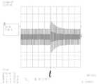
한편, 도 5 는 본 발명에 따른 일체형 가속도계·각속도계 구동 시스템(100)을 통해 가속도 인가 시 진동 폭의 변화를 나타낸 그래프로서, t=0 초에서 약 5g에 해당하는 가속도가 인가된 경우 진동 폭 신호는 빠르게 정상상태로 수렴하며, 이때 정상상태에서의 진동 폭은 가속도가 인가되기 전의 진동 폭 신호와 동일하다. 따라서, 이러한 일정한 진동 폭을 유지하도록 하는 제어신호를 복조함으로써, 인가되는 가속도 신호를 계산할 수 있음을 알 수 있다.On the other hand, Figure 5 is a graph showing the change in the vibration width when the acceleration is applied through the integrated accelerometer / angular
도 6 은 본 발명에 따른 일체형 가속도계·각속도계 구동 시스템(100)을 통해 각속도 인가 시 제어기(164)가 동작하는 결과를 나타내는 그래프로서, t<0의 영역은 제어기(164)가 동작하지 않는 개루프 시험 결과이며, t>0의 영역은 제어기(164)가 동작하는 시험 결과이다. 또한, a 신호는 각속도계축 방향으로 출력되는 변위신호이며, b는 제어기(164)의 출력신호이다.FIG. 6 is a graph showing a result of the
즉, 제어기(164)가 동작하는 순간 각속도계의 검출축 변위신호는 0에 가까운 값으로 제어되며, 이때 변위신호를 억제하기 위한 제어신호가 변위신호에 비례하는 값을 출력하게 되며, 이러한 제어신호를 변조함으로써, 각속도를 계산할 수 있다.That is, the instantaneous displacement signal of the detection axis of the tachometer is controlled to a value close to zero when the
이상으로 본 발명의 기술적 사상을 예시하기 위한 바람직한 실시예와 관련하여 설명하고 도시하였지만, 본 발명은 이와 같이 도시되고 설명된 그대로의 구성 및 작용에만 국한되는 것이 아니며, 기술적 사상의 범주를 일탈함이 없이 본 발명에 대해 다수의 변경 및 수정이 가능함을 당업자들은 잘 이해할 수 있을 것이다. 따라서, 그러한 모든 적절한 변경 및 수정과 균등물들도 본 발명의 범위에 속하는 것으로 간주되어야 할 것이다.As described above and described with reference to a preferred embodiment for illustrating the technical idea of the present invention, the present invention is not limited to the configuration and operation as shown and described as described above, it is a deviation from the scope of the technical idea It will be understood by those skilled in the art that many modifications and variations can be made to the invention without departing from the scope of the invention. Accordingly, all such suitable changes and modifications and equivalents should be considered to be within the scope of the present invention.
도 1 은 본 발명에 따른 일체형 가속도계·각속도계의 동작 원리를 설명하기 위한 일예시도.1 is an exemplary view for explaining the principle of operation of the integrated accelerometer, angular accelerometer according to the present invention.
도 2 는 본 발명에 따른 일체형 가속도계·각속도계 구동 시스템에 관한 전체 구성도.2 is an overall configuration diagram of an integrated accelerometer and angular accelerometer drive system according to the present invention.
도 3 은 본 발명에 따른 진폭유지 제어부에 관한 세부 구성도.3 is a detailed configuration diagram of an amplitude maintenance control unit according to the present invention;
도 4 는 본 발명에 따른 힘평형 제어부에 관한 세부 구성도.4 is a detailed configuration of the force balance control unit according to the present invention.
도 5 는 본 발명에 따른 일체형 가속도계·각속도계 구동 시스템을 통해 가속도 인가 시 진동 폭의 변화를 나타내는 그래프.5 is a graph showing a change in vibration width when acceleration is applied through the integrated accelerometer and angular accelerometer drive system according to the present invention.
도 6 은 본 발명에 따른 일체형 가속도계·각속도계 구동 시스템을 통해 각속도 인가 시 제어기가 동작하는 결과 그래프.6 is a result graph in which the controller operates when the angular velocity is applied through the integrated accelerometer and angular accelerometer driving system according to the present invention.
** 도면의 주요 부분에 대한 부호의 설명 **** Description of symbols for the main parts of the drawing **
110: 일체형 가속도계·각속도계 120: 가속도축 진동신호 취득부110: integrated accelerometer and angular speedometer 120: acceleration axis vibration signal acquisition unit
130: 진폭유지 제어부140: 가속도축 구동입력부130: amplitude maintenance control unit 140: acceleration axis drive input unit
150: 각속도축 진동신호 취득부160: 힘평형 제어부150: angular velocity axis vibration signal acquisition unit 160: force balance control unit
170: 각속도축 구동입력부170: angular velocity axis drive input unit
Claims (8)
Translated fromKoreanPriority Applications (7)
| Application Number | Priority Date | Filing Date | Title |
|---|---|---|---|
| KR1020070072411AKR100885416B1 (en) | 2007-07-19 | 2007-07-19 | Integrated accelerometer and angular accelerometer drive system |
| CN2007101880687ACN101349707B (en) | 2007-07-19 | 2007-11-23 | Accelerometer and gyroscope system integrated drive system |
| US11/956,582US7765869B2 (en) | 2007-07-19 | 2007-12-14 | Combined accelerometer and gyroscope system |
| AT07445046TATE513184T1 (en) | 2007-07-19 | 2007-12-18 | COMBINED SYSTEM WITH ACCELEROMETER AND GYROSCOPE |
| EP07445046AEP2017576B8 (en) | 2007-07-19 | 2007-12-18 | Combined accelerometer and gyroscope system |
| JP2007327591AJP2009025283A (en) | 2007-07-19 | 2007-12-19 | Integrated accelerometer and angular velocity meter system |
| AU2008200126AAU2008200126B2 (en) | 2007-07-19 | 2008-01-10 | Combined accelerometer and gyroscope system |
Applications Claiming Priority (1)
| Application Number | Priority Date | Filing Date | Title |
|---|---|---|---|
| KR1020070072411AKR100885416B1 (en) | 2007-07-19 | 2007-07-19 | Integrated accelerometer and angular accelerometer drive system |
Publications (2)
| Publication Number | Publication Date |
|---|---|
| KR20090009007A KR20090009007A (en) | 2009-01-22 |
| KR100885416B1true KR100885416B1 (en) | 2009-02-24 |
Family
ID=39876836
Family Applications (1)
| Application Number | Title | Priority Date | Filing Date |
|---|---|---|---|
| KR1020070072411AExpired - Fee RelatedKR100885416B1 (en) | 2007-07-19 | 2007-07-19 | Integrated accelerometer and angular accelerometer drive system |
Country Status (7)
| Country | Link |
|---|---|
| US (1) | US7765869B2 (en) |
| EP (1) | EP2017576B8 (en) |
| JP (1) | JP2009025283A (en) |
| KR (1) | KR100885416B1 (en) |
| CN (1) | CN101349707B (en) |
| AT (1) | ATE513184T1 (en) |
| AU (1) | AU2008200126B2 (en) |
Families Citing this family (33)
| Publication number | Priority date | Publication date | Assignee | Title |
|---|---|---|---|---|
| US8508039B1 (en) | 2008-05-08 | 2013-08-13 | Invensense, Inc. | Wafer scale chip scale packaging of vertically integrated MEMS sensors with electronics |
| US8250921B2 (en)* | 2007-07-06 | 2012-08-28 | Invensense, Inc. | Integrated motion processing unit (MPU) with MEMS inertial sensing and embedded digital electronics |
| US7934423B2 (en) | 2007-12-10 | 2011-05-03 | Invensense, Inc. | Vertically integrated 3-axis MEMS angular accelerometer with integrated electronics |
| US8141424B2 (en)* | 2008-09-12 | 2012-03-27 | Invensense, Inc. | Low inertia frame for detecting coriolis acceleration |
| US8047075B2 (en)* | 2007-06-21 | 2011-11-01 | Invensense, Inc. | Vertically integrated 3-axis MEMS accelerometer with electronics |
| US8462109B2 (en)* | 2007-01-05 | 2013-06-11 | Invensense, Inc. | Controlling and accessing content using motion processing on mobile devices |
| US8020441B2 (en)* | 2008-02-05 | 2011-09-20 | Invensense, Inc. | Dual mode sensing for vibratory gyroscope |
| US8952832B2 (en) | 2008-01-18 | 2015-02-10 | Invensense, Inc. | Interfacing application programs and motion sensors of a device |
| KR100871874B1 (en)* | 2007-07-06 | 2008-12-05 | 건국대학교 산학협력단 | Force Balance Control System Using Automatic Gain Control Loop |
| US20090027692A1 (en)* | 2007-07-24 | 2009-01-29 | Mitutoyo Corporation | Reference signal generating configuration for an interferometric miniature grating encoder readhead using fiber optic receiver channels |
| GB0720412D0 (en)* | 2007-10-18 | 2007-11-28 | Melexis Nv | Combined mems accelerometer and gyroscope |
| WO2009093769A2 (en)* | 2008-01-25 | 2009-07-30 | Konkuk University Industrial Cooperation Corp. | System for controlling the force rebalance using automatic gain controlling loop and method for the same |
| IT1391972B1 (en) | 2008-11-26 | 2012-02-02 | St Microelectronics Rousset | MICROELETTROMECHANICAL GYROSCOPE WITH ROTARY DRIVE MOVEMENT AND IMPROVED ELECTRICAL CHARACTERISTICS |
| IT1392741B1 (en) | 2008-12-23 | 2012-03-16 | St Microelectronics Rousset | MICROELETTROMECHANICAL GYROSCOPE WITH IMPROVED REJECTION OF ACCELERATION DISORDERS |
| US8291765B2 (en)* | 2009-05-04 | 2012-10-23 | Raytheon Company | Carrier modulating accelerometer |
| IT1394007B1 (en) | 2009-05-11 | 2012-05-17 | St Microelectronics Rousset | MICROELETTROMECANICAL STRUCTURE WITH IMPROVED REJECTION OF ACCELERATION DISORDERS |
| ITTO20091042A1 (en) | 2009-12-24 | 2011-06-25 | St Microelectronics Srl | MICROELETTROMECHANICAL INTEGRATED GYROSCOPE WITH IMPROVED DRIVE STRUCTURE |
| ITTO20110806A1 (en)* | 2011-09-12 | 2013-03-13 | St Microelectronics Srl | MICROELETTROMECANICAL DEVICE INTEGRATING A GYROSCOPE AND AN ACCELEROMETER |
| US10914584B2 (en) | 2011-09-16 | 2021-02-09 | Invensense, Inc. | Drive and sense balanced, semi-coupled 3-axis gyroscope |
| US9863769B2 (en) | 2011-09-16 | 2018-01-09 | Invensense, Inc. | MEMS sensor with decoupled drive system |
| US9714842B2 (en)* | 2011-09-16 | 2017-07-25 | Invensense, Inc. | Gyroscope self test by applying rotation on coriolis sense mass |
| RU2486468C1 (en)* | 2012-01-31 | 2013-06-27 | Открытое акционерное общество "Концерн "Центральный научно-исследовательский институт "Электроприбор" | Angular speed meter |
| US9304155B2 (en)* | 2012-12-19 | 2016-04-05 | Invensense, Inc. | Mode-tuning sense interface |
| KR101459442B1 (en)* | 2013-03-15 | 2014-11-07 | 현대자동차 주식회사 | Inertial sensor and measuring method thereof |
| US9404747B2 (en) | 2013-10-30 | 2016-08-02 | Stmicroelectroncs S.R.L. | Microelectromechanical gyroscope with compensation of quadrature error drift |
| WO2015083283A1 (en)* | 2013-12-06 | 2015-06-11 | 富士通株式会社 | Drive device, electronic equipment, drive control program, and drive signal-generating method |
| US9958271B2 (en) | 2014-01-21 | 2018-05-01 | Invensense, Inc. | Configuration to reduce non-linear motion |
| US9414165B2 (en) | 2014-01-27 | 2016-08-09 | Invensense, Inc. | Acoustic sensor resonant peak reduction |
| KR101665375B1 (en)* | 2014-12-05 | 2016-10-13 | 건국대학교 산학협력단 | Navigation system and method |
| JP6362556B2 (en)* | 2015-02-26 | 2018-07-25 | キヤノン株式会社 | Control device, imaging device, control method, program, and storage medium |
| US10488429B2 (en)* | 2017-02-28 | 2019-11-26 | General Electric Company | Resonant opto-mechanical accelerometer for use in navigation grade environments |
| CN114252147B (en)* | 2021-12-22 | 2024-10-18 | 昆山丘钛微电子科技股份有限公司 | Detection method and device for vibrating table |
| CN115047215B (en)* | 2022-02-18 | 2023-03-21 | 太原理工大学 | Triaxial vibration acceleration signal coupling correction detection system and method |
Citations (3)
| Publication number | Priority date | Publication date | Assignee | Title |
|---|---|---|---|---|
| KR20060124267A (en)* | 2005-05-31 | 2006-12-05 | 재단법인서울대학교산학협력재단 | Planar triaxial inertial measurement system without misalignment |
| KR100711261B1 (en)* | 2006-06-21 | 2007-04-25 | (주)마이크로인피니티 | Space recognition method of input device and device |
| KR20070072319A (en)* | 2005-12-30 | 2007-07-04 | 재단법인서울대학교산학협력재단 | Method and device for measuring angular velocity using two acceleration sensors |
Family Cites Families (19)
| Publication number | Priority date | Publication date | Assignee | Title |
|---|---|---|---|---|
| US4566327A (en)* | 1982-04-21 | 1986-01-28 | Rockwell International Corporation | System and technique for bandwidth improvement in multifunction sensors |
| US5205171A (en)* | 1991-01-11 | 1993-04-27 | Northrop Corporation | Miniature silicon accelerometer and method |
| US5481914A (en)* | 1994-03-28 | 1996-01-09 | The Charles Stark Draper Laboratory, Inc. | Electronics for coriolis force and other sensors |
| JPH0854242A (en)* | 1994-08-12 | 1996-02-27 | Murata Mfg Co Ltd | Oscillation gyro |
| US6578420B1 (en)* | 1997-01-28 | 2003-06-17 | Microsensors, Inc. | Multi-axis micro gyro structure |
| JPH10318755A (en)* | 1997-05-22 | 1998-12-04 | Toyota Motor Corp | Acceleration angular velocity sensor |
| JP3264884B2 (en)* | 1998-05-11 | 2002-03-11 | 三菱電機株式会社 | Capacitance detection circuit |
| US6253612B1 (en)* | 1998-06-05 | 2001-07-03 | Integrated Micro Instruments, Inc. | Generation of mechanical oscillation applicable to vibratory rate gyroscopes |
| US6481283B1 (en) | 1999-04-05 | 2002-11-19 | Milli Sensor Systems & Actuators, Inc. | Coriolis oscillating gyroscopic instrument |
| JP2001264071A (en) | 2000-03-17 | 2001-09-26 | Aisin Seiki Co Ltd | Vibrator drive |
| US20030033850A1 (en) | 2001-08-09 | 2003-02-20 | Challoner A. Dorian | Cloverleaf microgyroscope with electrostatic alignment and tuning |
| US6725719B2 (en)* | 2002-04-17 | 2004-04-27 | Milli Sensor Systems And Actuators, Inc. | MEMS-integrated inertial measurement units on a common substrate |
| US6701786B2 (en) | 2002-04-29 | 2004-03-09 | L-3 Communications Corporation | Closed loop analog gyro rate sensor |
| US6848304B2 (en) | 2003-04-28 | 2005-02-01 | Analog Devices, Inc. | Six degree-of-freedom micro-machined multi-sensor |
| CN100437116C (en)* | 2003-04-28 | 2008-11-26 | 模拟器件公司 | Micro-machined multi-sensor providing 2-axes of acceleration sensing and 1-axis of angular rate sensing |
| US6928873B2 (en)* | 2003-11-01 | 2005-08-16 | Chung-Shan Institute Of Science And Technology | Silicon dual inertial sensors |
| JP2005308530A (en)* | 2004-04-21 | 2005-11-04 | Denso Corp | Angular speed/acceleration composite sensor |
| JP2006071335A (en)* | 2004-08-31 | 2006-03-16 | Denso Corp | Angular velocity sensor and its driving method |
| US20060169041A1 (en)* | 2005-02-02 | 2006-08-03 | Madni Asad M | Combined gyroscope and 2-axis accelerometer |
- 2007
- 2007-07-19KRKR1020070072411Apatent/KR100885416B1/ennot_activeExpired - Fee Related
- 2007-11-23CNCN2007101880687Apatent/CN101349707B/ennot_activeExpired - Fee Related
- 2007-12-14USUS11/956,582patent/US7765869B2/ennot_activeExpired - Fee Related
- 2007-12-18ATAT07445046Tpatent/ATE513184T1/ennot_activeIP Right Cessation
- 2007-12-18EPEP07445046Apatent/EP2017576B8/ennot_activeNot-in-force
- 2007-12-19JPJP2007327591Apatent/JP2009025283A/enactivePending
- 2008
- 2008-01-10AUAU2008200126Apatent/AU2008200126B2/ennot_activeCeased
Patent Citations (3)
| Publication number | Priority date | Publication date | Assignee | Title |
|---|---|---|---|---|
| KR20060124267A (en)* | 2005-05-31 | 2006-12-05 | 재단법인서울대학교산학협력재단 | Planar triaxial inertial measurement system without misalignment |
| KR20070072319A (en)* | 2005-12-30 | 2007-07-04 | 재단법인서울대학교산학협력재단 | Method and device for measuring angular velocity using two acceleration sensors |
| KR100711261B1 (en)* | 2006-06-21 | 2007-04-25 | (주)마이크로인피니티 | Space recognition method of input device and device |
Also Published As
| Publication number | Publication date |
|---|---|
| EP2017576A3 (en) | 2010-03-10 |
| JP2009025283A (en) | 2009-02-05 |
| EP2017576B1 (en) | 2011-06-15 |
| ATE513184T1 (en) | 2011-07-15 |
| CN101349707A (en) | 2009-01-21 |
| US20090019933A1 (en) | 2009-01-22 |
| AU2008200126B2 (en) | 2009-08-20 |
| CN101349707B (en) | 2010-09-29 |
| KR20090009007A (en) | 2009-01-22 |
| US7765869B2 (en) | 2010-08-03 |
| AU2008200126A1 (en) | 2009-02-05 |
| EP2017576A2 (en) | 2009-01-21 |
| EP2017576B8 (en) | 2012-03-21 |
Similar Documents
| Publication | Publication Date | Title |
|---|---|---|
| KR100885416B1 (en) | Integrated accelerometer and angular accelerometer drive system | |
| TWI482946B (en) | Vibrationskompensation fuer drehratensensoren | |
| US11390517B2 (en) | Systems and methods for bias suppression in a non-degenerate MEMS sensor | |
| KR101314151B1 (en) | Calibration Method for 6-Axis Vibration Sensors using Periodic Angular Vibration and Its Realization System | |
| JP6629691B2 (en) | Sensor packages and self-driving vehicles | |
| CN106918351A (en) | A kind of micro mechanical gyroscope automatic fault selftesting method based on quadrature error signal | |
| Aktakka et al. | On-chip characterization of scale-factor of a MEMS gyroscope via a micro calibration platform | |
| EP2498051A2 (en) | Inertial sensor | |
| EP3237844B1 (en) | Method for suppresion of g-sensitivity of mems gyroscope | |
| KR100871874B1 (en) | Force Balance Control System Using Automatic Gain Control Loop | |
| Lu et al. | An intentional acoustic interference approach to control output signals of MEMS gyroscope based on short-time Fourier analysis | |
| EP3798642B1 (en) | Coriolis vibratory accelerometer system | |
| EP2235476A2 (en) | System for controlling the force rebalance using automatic gain controlling loop and method for the same | |
| Gavcar et al. | An automatic acceleration compensation system for a single-mass MEMS gyroscope | |
| US12227409B2 (en) | Robust inertial sensor self-test | |
| JP5266528B2 (en) | Angular velocity sensor, angular velocity signal correction device | |
| JPH0612913U (en) | Rotation detection sensor module | |
| RU2630542C1 (en) | Integral micro-mechanical gyroscope | |
| Beňo et al. | Control and stabilization of single-wheeled electric vehicle with BLDC engine | |
| JP2013120180A (en) | Angular velocity sensor | |
| JP2013205413A (en) | Inertial sensor and angular velocity measuring method using the same | |
| JPS62280609A (en) | How to adjust the circulation drive type rate gyro | |
| JPH11304493A (en) | Vibration type angular velocity detector | |
| CN105549636A (en) | System and method for stabilizing visual axis with auxiliary assistance of accelerometer under vibration environment | |
| JP2013044658A (en) | Angular velocity sensor |
Legal Events
| Date | Code | Title | Description |
|---|---|---|---|
| A201 | Request for examination | ||
| PA0109 | Patent application | St.27 status event code:A-0-1-A10-A12-nap-PA0109 | |
| PA0201 | Request for examination | St.27 status event code:A-1-2-D10-D11-exm-PA0201 | |
| P11-X000 | Amendment of application requested | St.27 status event code:A-2-2-P10-P11-nap-X000 | |
| P13-X000 | Application amended | St.27 status event code:A-2-2-P10-P13-nap-X000 | |
| D13-X000 | Search requested | St.27 status event code:A-1-2-D10-D13-srh-X000 | |
| D14-X000 | Search report completed | St.27 status event code:A-1-2-D10-D14-srh-X000 | |
| E902 | Notification of reason for refusal | ||
| PE0902 | Notice of grounds for rejection | St.27 status event code:A-1-2-D10-D21-exm-PE0902 | |
| E13-X000 | Pre-grant limitation requested | St.27 status event code:A-2-3-E10-E13-lim-X000 | |
| P11-X000 | Amendment of application requested | St.27 status event code:A-2-2-P10-P11-nap-X000 | |
| P13-X000 | Application amended | St.27 status event code:A-2-2-P10-P13-nap-X000 | |
| PG1501 | Laying open of application | St.27 status event code:A-1-1-Q10-Q12-nap-PG1501 | |
| E701 | Decision to grant or registration of patent right | ||
| PE0701 | Decision of registration | St.27 status event code:A-1-2-D10-D22-exm-PE0701 | |
| GRNT | Written decision to grant | ||
| PR0701 | Registration of establishment | St.27 status event code:A-2-4-F10-F11-exm-PR0701 | |
| PR1002 | Payment of registration fee | Fee payment year number:1 St.27 status event code:A-2-2-U10-U11-oth-PR1002 | |
| PG1601 | Publication of registration | St.27 status event code:A-4-4-Q10-Q13-nap-PG1601 | |
| FPAY | Annual fee payment | Payment date:20120111 Year of fee payment:4 | |
| PR1001 | Payment of annual fee | Fee payment year number:4 St.27 status event code:A-4-4-U10-U11-oth-PR1001 | |
| R18-X000 | Changes to party contact information recorded | St.27 status event code:A-5-5-R10-R18-oth-X000 | |
| LAPS | Lapse due to unpaid annual fee | ||
| PC1903 | Unpaid annual fee | Not in force date:20130219 Payment event data comment text:Termination Category : DEFAULT_OF_REGISTRATION_FEE St.27 status event code:A-4-4-U10-U13-oth-PC1903 | |
| PC1903 | Unpaid annual fee | Ip right cessation event data comment text:Termination Category : DEFAULT_OF_REGISTRATION_FEE Not in force date:20130219 St.27 status event code:N-4-6-H10-H13-oth-PC1903 | |
| R18-X000 | Changes to party contact information recorded | St.27 status event code:A-5-5-R10-R18-oth-X000 | |
| PN2301 | Change of applicant | St.27 status event code:A-5-5-R10-R11-asn-PN2301 St.27 status event code:A-5-5-R10-R13-asn-PN2301 | |
| R18-X000 | Changes to party contact information recorded | St.27 status event code:A-5-5-R10-R18-oth-X000 | |
| R18-X000 | Changes to party contact information recorded | St.27 status event code:A-5-5-R10-R18-oth-X000 | |
| R18-X000 | Changes to party contact information recorded | St.27 status event code:A-5-5-R10-R18-oth-X000 | |
| R18-X000 | Changes to party contact information recorded | St.27 status event code:A-5-5-R10-R18-oth-X000 |