KR100884142B1 - Device control system, method and apparatus for server-based or peer-to-peer network environment - Google Patents
Device control system, method and apparatus for server-based or peer-to-peer network environmentDownload PDFInfo
- Publication number
- KR100884142B1 KR100884142B1KR1020067015299AKR20067015299AKR100884142B1KR 100884142 B1KR100884142 B1KR 100884142B1KR 1020067015299 AKR1020067015299 AKR 1020067015299AKR 20067015299 AKR20067015299 AKR 20067015299AKR 100884142 B1KR100884142 B1KR 100884142B1
- Authority
- KR
- South Korea
- Prior art keywords
- controller
- network
- server
- control
- data
- Prior art date
- Legal status (The legal status is an assumption and is not a legal conclusion. Google has not performed a legal analysis and makes no representation as to the accuracy of the status listed.)
- Expired - Fee Related
Links
Images


Classifications
- H—ELECTRICITY
- H04—ELECTRIC COMMUNICATION TECHNIQUE
- H04L—TRANSMISSION OF DIGITAL INFORMATION, e.g. TELEGRAPHIC COMMUNICATION
- H04L12/00—Data switching networks
- H04L12/02—Details
- H04L12/12—Arrangements for remote connection or disconnection of substations or of equipment thereof
- H—ELECTRICITY
- H04—ELECTRIC COMMUNICATION TECHNIQUE
- H04L—TRANSMISSION OF DIGITAL INFORMATION, e.g. TELEGRAPHIC COMMUNICATION
- H04L12/00—Data switching networks
- H04L12/28—Data switching networks characterised by path configuration, e.g. LAN [Local Area Networks] or WAN [Wide Area Networks]
- H04L12/2803—Home automation networks
- H04L12/2816—Controlling appliance services of a home automation network by calling their functionalities
- H04L12/282—Controlling appliance services of a home automation network by calling their functionalities based on user interaction within the home
- H—ELECTRICITY
- H04—ELECTRIC COMMUNICATION TECHNIQUE
- H04L—TRANSMISSION OF DIGITAL INFORMATION, e.g. TELEGRAPHIC COMMUNICATION
- H04L12/00—Data switching networks
- H04L12/28—Data switching networks characterised by path configuration, e.g. LAN [Local Area Networks] or WAN [Wide Area Networks]
- H—ELECTRICITY
- H04—ELECTRIC COMMUNICATION TECHNIQUE
- H04L—TRANSMISSION OF DIGITAL INFORMATION, e.g. TELEGRAPHIC COMMUNICATION
- H04L12/00—Data switching networks
- H04L12/28—Data switching networks characterised by path configuration, e.g. LAN [Local Area Networks] or WAN [Wide Area Networks]
- H04L12/2803—Home automation networks
- H04L12/2805—Home Audio Video Interoperability [HAVI] networks
Landscapes
- Engineering & Computer Science (AREA)
- Computer Networks & Wireless Communication (AREA)
- Signal Processing (AREA)
- Automation & Control Theory (AREA)
- Multimedia (AREA)
- Human Computer Interaction (AREA)
- Computer And Data Communications (AREA)
- Selective Calling Equipment (AREA)
Abstract
Translated fromKoreanDescription
Translated fromKorean본 발명은 일반적으로 디바이스 제어에 관한 것이다. 상세하게는, 본 발명은 서버-기반 또는 피어-투-피어 네트워크 환경에서 전자 디바이스를 제어하는 시스템, 방법 및 장치에 관한 것이다.The present invention generally relates to device control. In particular, the present invention relates to systems, methods, and apparatus for controlling electronic devices in a server-based or peer-to-peer network environment.
계속 증가하는 수의 다양한 원격 제어가능 전자 디바이스가 가정 및 사무실 환경에서 이용되고 있다. 이러한 디바이스는 UPnP™ 프로토콜에 부합하는 디바이스는 물론 적외선(IR) 또는 직렬 명령 코드를 구현하는 핸드헬드 리모콘에 의한 제어에 적합하게 구성된 종래의 가전 기기 등의 유선 또는 무선 네트워크를 통한 제어에 적합하도록 구성된 전자 디바이스를 포함한다.An ever increasing number of various remotely controllable electronic devices are being used in home and office environments. These devices are designed to be suitable for control over wired or wireless networks, such as conventional home appliances, which are suited for control by a handheld remote control that implements infrared (IR) or serial command codes as well as devices conforming to the UPnP ™ protocol. An electronic device.
종래의 디바이스 제어 해결책은 단일의 핸드헬드 제어기를 통하는 등, 통합된 인터페이스를 통해 상기한 디바이스 유형들을 제어하는 수단을 제공하지 않는다. 게다가, 종래의 디바이스 제어 해결책은 피어-투-피어 네트워크 환경에서 복수의 이러한 제어기들 간의 동기화를 보장하는 수단, 이러한 제어기들 간에 커스텀 구성을 전송하는 수단, 또는 이러한 제어기를 피어-투-피어 네트워크 환경에서 서 버-기반 네트워크 환경으로 또한 그 역으로 마이그레이션하는 수단을 제공하지 않는다.Conventional device control solutions do not provide a means to control the device types through an integrated interface, such as through a single handheld controller. In addition, conventional device control solutions include means for ensuring synchronization between a plurality of such controllers in a peer-to-peer network environment, means for transferring a custom configuration between such controllers, or a peer-to-peer network environment for such controllers. It does not provide a means for migrating from server to server-based network environment and vice versa.
본 명세서에 기술된 본 발명은 단일의 핸드헬드 제어기를 통하는 등, 통합된 인터페이스를 통해 다양한 디바이스 유형들을 제어하는 수단을 제공하는 디바이스 제어 시스템에서 사용된다. 본 발명에 따르면, 동기화 프로토콜은 피어-투-피어 네트워크 환경에서 복수의 이러한 제어기들 간의 동기화를 보장하고, 이러한 제어기들 간에 커스텀 구성을 전송하는 수단을 제공하며, 이러한 제어기를 피어-투-피어 네트워크 환경에서 서버-기반 네트워크 환경으로 마이그레이션하는 수단을 제공한다.The invention described herein is used in a device control system that provides a means for controlling various device types via an integrated interface, such as through a single handheld controller. According to the present invention, a synchronization protocol provides a means to ensure synchronization between a plurality of such controllers in a peer-to-peer network environment, and to transfer a custom configuration between such controllers, and to provide such a controller for a peer-to-peer network. It provides a means of migrating from an environment to a server-based network environment.
상세하게는, 본 발명의 실시예는 제1 제어기를 제2 제어기와 동기화시키는 방법을 제공하며, 제1 및 제2 제어기 각각은 하나 이상의 전자 디바이스를 원격 제어하도록 구성되어 있다. 이 방법은, 제2 제어기를 발견하는 단계, 제1 및 제2 제어기를 동기화시키기 위한 제1 제어기 동기화 데이터를 발생하는 단계, 및 제1 제어기 동기화 데이터에 관한 메시지를 제2 제어기로 전송하는 단계를 포함한다. 제1 제어기 동기화 데이터는 하나 이상의 전자 디바이스 중 하나의 구성, 상태 및/또는 동작을 변경하는 명령의 실행에 응답하여, 제1 제어기의 제어 구성을 변경하는 명령의 실행에 응답하여, 또는 하나 이상의 전자 디바이스 중 적어도 하나의 구성, 상태 및/또는 동작의 검출된 변경에 응답하여 발생된다.In particular, an embodiment of the present invention provides a method of synchronizing a first controller with a second controller, each of which is configured to remotely control one or more electronic devices. The method includes discovering a second controller, generating first controller synchronization data for synchronizing the first and second controllers, and sending a message regarding the first controller synchronization data to the second controller. Include. The first controller synchronization data is in response to the execution of the command to change the configuration, state and / or operation of one of the one or more electronic devices, in response to the execution of the command to change the control configuration of the first controller, or at least one electronic. In response to the detected change in configuration, state and / or operation of at least one of the devices.
본 발명의 다른 실시예에서, 하나 이상의 전자 디바이스를 원격 제어하는 장치가 제공된다. 이 장치는, 네트워크를 통한 통신에 적합하도록 구성된 네트워크 인터페이스, 사용자 입력을 수신하도록 구성되어 있는 사용자 인터페이스, 및 네트워크 인터페이스 및 사용자 인터페이스에 연결되어, 사용자 입력에 응답하여 명령을 실행하도록 구성되어 있는 제어 로직을 포함한다. 이 제어 로직은 또한 네트워크에 통신 연결되어 있는 하나 이상의 전자 디바이스를 제어하기 위한 제2 장치를 발견하고, 상기 장치를 제2 장치와 동기화시키기 위한 동기화 데이터를 발생하며, 동기화 데이터에 관한 메시지를 네트워크 인터페이스를 통해 제2 장치로 전송하도록 구성되어 있다. 동기화 데이터는 하나 이상의 전자 디바이스 중 하나의 구성, 상태 및/또는 동작을 변경하는 명령의 실행에 응답하여, 상기 장치의 제어 구성을 변경하는 명령의 실행에 응답하여, 또는 하나 이상의 전자 디바이스 중 적어도 하나의 구성, 상태 및/또는 동작의 검출된 변경에 응답하여 발생될 수 있다.In another embodiment of the present invention, an apparatus for remotely controlling one or more electronic devices is provided. The apparatus includes a network interface configured for communication over a network, a user interface configured to receive user input, and control logic coupled to the network interface and the user interface and configured to execute a command in response to the user input. It includes. The control logic also finds a second device for controlling one or more electronic devices that are communicatively connected to the network, generates synchronization data for synchronizing the device with the second device, and sends a message regarding the synchronization data to the network interface. And to transmit to the second device via. The synchronization data may be in response to the execution of the command to change the configuration, state and / or operation of one of the one or more electronic devices, in response to the execution of the command to change the control configuration of the apparatus, or at least one of the one or more electronic devices. May be generated in response to the detected change in the configuration, state, and / or operation of the.
본 발명의 또 다른 실시예는 디바이스 제어를 위한 시스템이 제공된다. 이 시스템은, 전자 디바이스, 및 무선 네트워크 등의 네트워크를 통해 상기 전자 디바이스에 또한 서로에 통신 연결되어 있는 제1 및 제2 제어기를 포함한다. 제1 및 제2 제어기 각각은 네트워크를 통해 전자 디바이스를 원격 제어하도록 구성되어 있다. 제1 제어기는 또한 제2 제어기를 발견하고, 제1 및 제2 제어기를 동기화시키기 위한 제1 제어기 동기화 데이터를 발생하며, 제1 제어기 동기화 데이터에 관한 메시지를 네트워크를 통해 제2 제어기로 전송하도록 구성되어 있다. 제1 제어기 동기화 데이터는 전자 디바이스의 구성, 상태 및/또는 동작을 변경하는 명령의 실행에 응답하여, 제1 제어기의 제어 구성을 변경하는 명령의 실행에 응답하여, 또는 전자 디바이스의 구성, 상태 및/또는 동작의 검출된 변경에 응답하여 발생될 수 있다.Yet another embodiment of the present invention provides a system for device control. The system includes an electronic device and first and second controllers communicatively connected to each other and to the electronic device via a network such as a wireless network. Each of the first and second controllers is configured to remotely control the electronic device via a network. The first controller is further configured to discover the second controller, generate first controller synchronization data for synchronizing the first and second controllers, and send a message regarding the first controller synchronization data over the network to the second controller. It is. The first controller synchronization data is in response to the execution of the command to change the configuration, state and / or operation of the electronic device, in response to the execution of the command to change the control configuration of the first controller, or to the configuration, state and And / or in response to a detected change in operation.
본 발명의 추가의 실시예에서, 제1 제어기를 제2 제어기와 동기화시키는 방법이 제공되며, 여기서 제1 및 제2 제어기 각각은 하나 이상의 전자 디바이스를 원격 제어하도록 구성되어 있다. 이 방법은, 제2 제어기를 발견하는 단계, 이전의 동기화 이래로 일어난 하나 이상의 제1 제어기 이벤트에 관한 제1 데이터를 제2 제어기로 전송하는 단계, 및 이전의 동기화 이래로 일어난 하나 이상의 제2 제어기 이벤트에 관한 제2 데이터를 제2 제어기로부터 수신하는 단계를 포함한다. 이 방법은 제1 및 제2 데이터에 기초하여 이벤트 로그를 갱신하는 단계를 더 포함할 수 있으며, 이 단계는 제1 제어기 이벤트에 관한 데이터를 제2 제어기 이벤트에 관한 데이터와 비교하는 단계, 및 제1 제어기 이벤트에 관한 데이터가 제2 제어기 이벤트에 관한 데이터와 상충하는 경우, 제1 제어기 이벤트와 연관된 타임스탬프가 상기 제2 제어기 이벤트와 연관된 타임스탬프보다 이른 경우에만 이벤트 로그를 갱신하는 단계를 더 수반할 수 있다. 이 방법은 제2 데이터에 기초하여 제1 제어기의 제어 구성을 제2 제어기의 제어 구성과 일치(match)하도록 변경하는 단계를 더 포함할 수 있다.In a further embodiment of the present invention, a method of synchronizing a first controller with a second controller is provided, wherein each of the first and second controllers is configured to remotely control one or more electronic devices. The method includes the steps of: discovering a second controller, transmitting first data about one or more first controller events that have occurred since the previous synchronization to the second controller, and one or more second controller events that have occurred since the previous synchronization. Receiving from the second controller related second data. The method may further comprise updating the event log based on the first and second data, wherein comparing the data regarding the first controller event with the data relating to the second controller event, and If the data relating to the first controller event conflicts with the data relating to the second controller event, further comprising updating the event log only if the timestamp associated with the first controller event is earlier than the timestamp associated with the second controller event. can do. The method may further include changing the control configuration of the first controller to match the control configuration of the second controller based on the second data.
다른 실시예에서, 하나 이상의 전자 디바이스를 원격 제어하는 장치가 제공된다. 이 장치는, 네트워크를 통한 통신에 적합하도록 구성된 네트워크 인터페이스, 사용자 입력을 수신하도록 구성되어 있는 사용자 인터페이스, 및 네트워크 인터페이스 및 사용자 인터페이스에 연결되어, 사용자 입력에 응답하여 명령을 실행하도록 구성되어 있는 제어 로직을 포함한다. 이 제어 로직은 또한 네트워크에 통신 연결되어 있는 하나 이상의 전자 디바이스를 제어하기 위한 제2 장치를 발견하고, 이전의 동기화 이래로 일어난 하나 이상의 제1 제어기 이벤트에 관한 제1 데이터를 제2 장치로 전송하며, 이전의 동기화 이래로 일어난 하나 이상의 제2 제어기 이벤트에 관한 제2 데이터를 제2 장치로부터 수신하도록 구성되어 있다. 이 제어 로직은 또한 제1 및 제2 데이터에 기초하여 메모리에 저장된 이벤트 로그를 갱신하도록 구성될 수 있다. 이 갱신하는 동작은 또한 제1 제어기 이벤트에 관한 데이터를 제2 제어기 이벤트에 관한 데이터와 비교하는 동작, 및 제1 제어기 이벤트에 관한 데이터가 제2 제어기 이벤트에 관한 데이터와 상충하는 경우, 제1 제어기 이벤트와 연관된 타임스탬프가 제2 제어기 이벤트와 연관된 타임스탬프보다 이른 경우에만 이벤트 로그를 갱신하는 동작을 수반할 수 있다. 이 제어 로직은 또한 제2 데이터에 기초하여 상기 장치의 제어 구성을 제2 장치의 제어 구성과 일치하게 변경하도록 구성되어 있을 수 있다.In another embodiment, an apparatus for remotely controlling one or more electronic devices is provided. The apparatus includes a network interface configured for communication over a network, a user interface configured to receive user input, and control logic coupled to the network interface and the user interface and configured to execute a command in response to the user input. It includes. The control logic also finds a second apparatus for controlling one or more electronic devices that are communicatively connected to the network, and transmits first data about one or more first controller events that have occurred since the previous synchronization, to the second apparatus, And receive second data from the second device regarding one or more second controller events that have occurred since the previous synchronization. This control logic may also be configured to update the event log stored in memory based on the first and second data. This updating operation also includes comparing data relating to the first controller event with data relating to the second controller event, and if the data relating to the first controller event conflict with the data relating to the second controller event. It may involve updating the event log only if the timestamp associated with the event is earlier than the timestamp associated with the second controller event. The control logic may also be configured to change the control configuration of the device to match the control configuration of the second device based on the second data.
또 다른 실시예에서, 디바이스 제어를 위한 시스템이 제공된다. 이 시스템은, 전자 디바이스, 및 무선 네트워크 등의 네트워크를 통해 전자 디바이스에 또한 서로에 통신 연결되어 있는 제1 및 제2 제어기를 포함한다. 제1 및 제2 제어기 각각은 네트워크를 통해 전자 디바이스를 원격 제어하도록 구성되어 있다. 제1 제어기는 또한 제2 제어기를 발견하고, 이전의 동기화 이래로 일어난 하나 이상의 제1 제어기 이벤트에 관한 제1 데이터를 제2 제어기로 전송하며, 이전의 동기화 이래로 일어난 하나 이상의 제2 제어기 이벤트에 관한 제2 데이터를 제2 제어기로부터 수신하도록 구성되어 있다. 제1 제어기는 제1 및 제2 데이터에 기초하여 이벤트 로그를 갱신하도록 구성되어 있을 수 있으며, 이 갱신하는 동작은 또한 제1 제어기 이벤트에 관한 데이터를 제2 제어기 이벤트에 관한 데이터와 비교하는 동작, 및 제1 제어기 이벤트에 관한 데이터가 제2 제어기 이벤트에 관한 데이터와 상충하는 경우, 제1 제어기 이벤트와 연관된 타임스탬프가 제2 제어기 이벤트와 연관된 타임스탬프보다 이른 경우에만 이벤트 로그를 갱신하는 동작을 수반할 수 있다. 제1 제어기는 또한 제2 데이터에 기초하여 제1 제어기의 제어 구성을 제2 제어기의 제어 구성과 일치하게 변경하도록 구성될 수 있다.In yet another embodiment, a system for device control is provided. The system includes an electronic device and first and second controllers that are communicatively connected to one another and to the electronic device via a network such as a wireless network. Each of the first and second controllers is configured to remotely control the electronic device via a network. The first controller also discovers the second controller, sends first data about one or more first controller events that have occurred since the previous synchronization, and transmits first data about the one or more second controller events that have occurred since the previous synchronization. 2 is configured to receive data from the second controller. The first controller may be configured to update the event log based on the first and second data, the updating operation further comprising comparing the data relating to the first controller event with the data relating to the second controller event, And updating the event log only if the timestamp associated with the first controller event is earlier than the timestamp associated with the second controller event if the data regarding the first controller event is in conflict with the data regarding the second controller event. can do. The first controller may also be configured to change the control configuration of the first controller to match the control configuration of the second controller based on the second data.
부가의 실시예에서, 하나 이상의 전자 디바이스를 원격 제어하도록 구성된 제어기를 독립형 모드(stand-alone mode)에서 클라이언트-서버 모드(client-server mode)로 마이그레이션(migrate)는 방법이 제공된다. 처음에, 제어기는 독립형 모드에서 제어기에 의해 유지되는 제어 구성에 따라 하나 이상의 전자 디바이스를 원격 제어한다. 이 방법은, 서버를 발견하는 단계, 제어기에 의해 유지되는 제어 구성에 관한 데이터를 서버로 전송하는 단계, 및 뒤이어서 서버에 의해 유지되는 제어 구성에 따라 하나 이상의 전자 디바이스를 제어하는 단계를 포함한다.In a further embodiment, a method is provided for migrating a controller configured to remotely control one or more electronic devices from stand-alone mode to client-server mode. Initially, the controller remotely controls one or more electronic devices according to the control configuration maintained by the controller in the standalone mode. The method includes discovering a server, transmitting data regarding a control configuration maintained by the controller to the server, and subsequently controlling one or more electronic devices in accordance with the control configuration maintained by the server.
다른 실시예에서, 하나 이상의 전자 디바이스를 원격 제어하는 장치가 제공된다. 이 장치는, 네트워크를 통한 통신에 적합하도록 구성된 네트워크 인터페이스, 사용자 입력을 수신하도록 구성되어 있는 사용자 인터페이스, 및 네트워크 인터페이스 및 사용자 인터페이스에 연결되어, 사용자 입력에 응답하여 명령을 실행하도록 구성되어 있는 제어 로직을 포함한다. 이 제어 로직은 또한 네트워크에 통신 연결된 서버를 발견하고, 상기 장치에 의해 유지되는 제어 구성에 관한 데이터를 서버로 전송하며, 뒤이어서 상기 장치에 의해 유지되는 제어 구성에 따르는 대신에 서버에 의해 유지되는 제어 구성에 따라 하나 이상의 전자 디바이스를 제어하도록 구성되어 있다.In another embodiment, an apparatus for remotely controlling one or more electronic devices is provided. The apparatus includes a network interface configured for communication over a network, a user interface configured to receive user input, and control logic coupled to the network interface and the user interface and configured to execute a command in response to the user input. It includes. This control logic also finds a server that is communicatively connected to the network, sends data about the control configuration maintained by the device to the server, and subsequently controls maintained by the server instead of following the control configuration maintained by the device. It is configured to control one or more electronic devices according to the configuration.
또 다른 실시예에서, 디바이스 제어 시스템이 제공된다. 이 시스템은, 전자 디바이스, 무선 네트워크 등의 네트워크를 통해 전자 디바이스에 통신 연결되어 있는 제어기 - 이 제어기는 네트워크를 통해 전자 디바이스를 원격 제어하도록 구성되어 있음 -, 및 네트워크를 통해 전자 디바이스 및 제어기에 통신 연결되어 있는 서버를 포함한다. 이 제어기는 서버를 발견하고, 제어기에 의해 유지되는 제어 구성에 관한 데이터를 서버로 전송하며, 뒤이어서 제어기에 의해 유지되는 제어 구성에 따르는 대신에 서버에 의해 유지되는 제어 구성에 따라 전자 디바이스를 제어하도록 구성되어 있다.In yet another embodiment, a device control system is provided. The system includes a controller that is communicatively connected to the electronic device via a network such as an electronic device, a wireless network, the controller configured to remotely control the electronic device via the network, and to communicate with the electronic device and the controller via the network. Contains the server to which you are connected. The controller discovers the server, sends data about the control configuration maintained by the controller to the server, and subsequently controls the electronic device according to the control configuration maintained by the server instead of following the control configuration maintained by the controller. Consists of.
부가의 실시예에서, 하나 이상의 전자 디바이스를 원격 제어하도록 구성된 제어기를 클라이언트-서버 모드(client-server mode)에서 독립형 모드(stand-alone mode)로 마이그레이션(migrate)는 방법이 제공된다. 처음에, 제어기는 서버에 의해 유지되는 제어 구성에 따라 하나 이상의 전자 디바이스를 원격 제어한다. 이 방법은, 서버에 의해 유지되는 제어 구성에 관한 데이터를 서버로부터 수신하는 단계, 및 뒤이어서 제어기에 의해 유지되는 제어 구성에 따라 하나 이상의 전자 디바이스를 제어하는 단계를 포함한다.In a further embodiment, a method is provided for migrating a controller configured to remotely control one or more electronic devices from a client-server mode to a stand-alone mode. Initially, the controller remotely controls one or more electronic devices in accordance with the control configuration maintained by the server. The method includes receiving data from a server regarding a control configuration maintained by the server, and subsequently controlling one or more electronic devices in accordance with the control configuration maintained by the controller.
다른 실시예에서, 하나 이상의 전자 디바이스를 원격 제어하는 장치가 제공된다. 이 장치는, 네트워크를 통한 통신에 적합하도록 구성된 네트워크 인터페이스, 사용자 입력을 수신하도록 구성되어 있는 사용자 인터페이스, 및 네트워크 인터페이스 및 사용자 인터페이스에 연결되어, 사용자 입력에 응답하여 명령을 실행하도록 구성되어 있는 제어 로직을 포함한다. 이 제어 로직은 또한 네트워크에 통신 연결된 서버에 의해 유지되는 제어 구성에 관한 데이터를 서버로부터 수신하고, 뒤이어서 서버에 의해 유지되는 제어 구성에 따르는 대신에 상기 장치에 의해 유지되는 제어 구성에 따라 하나 이상의 전자 디바이스를 제어하도록 구성되어 있다.In another embodiment, an apparatus for remotely controlling one or more electronic devices is provided. The apparatus includes a network interface configured for communication over a network, a user interface configured to receive user input, and control logic coupled to the network interface and the user interface and configured to execute a command in response to the user input. It includes. This control logic also receives data from the server about the control configuration maintained by the server that is connected to the network and subsequently follows one or more electronics according to the control configuration maintained by the device instead of following the control configuration maintained by the server. It is configured to control the device.
또 다른 실시예에서, 디바이스 제어 시스템이 제공된다. 이 시스템은, 전자 디바이스, 무선 네트워크 등의 네트워크를 통해 전자 디바이스에 통신 연결되어 있는 제어기 - 이 제어기는 네트워크를 통해 전자 디바이스를 원격 제어하도록 구성되어 있음 -, 및 네트워크를 통해 전자 디바이스 및 제어기에 통신 연결된 서버를 포함한다. 이 제어기는 또한 서버에 의해 유지되는 제어 구성에 관한 데이터를 서버로부터 수신하고, 뒤이어서 서버에 의해 유지되는 제어 구성에 따르는 대신에 제어기에 의해 유지되는 제어 구성에 따라 전자 디바이스를 제어하도록 구성되어 있다.In yet another embodiment, a device control system is provided. The system includes a controller that is communicatively connected to the electronic device via a network such as an electronic device, a wireless network, the controller configured to remotely control the electronic device via the network, and to communicate with the electronic device and the controller via the network. Include a linked server. The controller is also configured to receive data about the control configuration maintained by the server from the server and subsequently control the electronic device according to the control configuration maintained by the controller instead of following the control configuration maintained by the server.
본 발명의 여러가지 실시예의 구조 및 동작 뿐만 아니라 본 발명의 추가의 특징 및 이점은 첨부 도면을 참조하여 이하에서 상세히 기술된다. 유의할 점은 본 발명이 본 명세서에 기술된 특정의 실시예에 한정되지 않는다는 것이다. 이러한 실시예는 단지 예시적인 목적으로 본 명세서에 제공되어 있다. 부가의 실시예들이 본 명세서에 포함된 개시 내용에 기초하면 당업자에게는 자명할 것이다.Further features and advantages of the present invention, as well as the structure and operation of various embodiments of the present invention, are described in detail below with reference to the accompanying drawings. Note that the present invention is not limited to the specific embodiments described herein. Such embodiments are provided herein for illustrative purposes only. Additional embodiments will be apparent to those of ordinary skill in the art based on the disclosure contained herein.
본 명세서에 포함되어 본 명세서의 일부를 형성하는 첨부 도면은 본 발명을 예시하며, 또한 상세한 설명과 함께 본 발명의 원리를 설명하도록 그리고 당업자가 본 발명을 수행하고 이용할 수 있도록 한다.The accompanying drawings, which are incorporated in and form a part of this specification, illustrate the invention, and together with the description serve to explain the principles of the invention and to enable those skilled in the art to make and use the invention.
도 1은 본 발명의 실시예에 따른 디바이스 제어 시스템의 구성요소를 나타낸 도면이다.1 is a view showing the components of the device control system according to an embodiment of the present invention.
도 2는 본 발명의 실시예에 따른 디바이스 제어 시스템의 특정의 구현을 나타낸 도면이다.2 is a diagram of a particular implementation of a device control system in accordance with an embodiment of the present invention.
도 3은 본 발명의 실시예에 따른 예시적인 제어기 구현을 나타낸 도면이다.3 illustrates an exemplary controller implementation in accordance with an embodiment of the present invention.
도 4는 본 발명의 실시예에 따른 제어기에 의해 저장될 수 있는 여러가지 소프트웨어 라이브러리를 개념적으로 나타낸 도면이다.4 conceptually illustrates various software libraries that may be stored by a controller in accordance with an embodiment of the present invention.
도 5는 본 발명의 실시예에 따른 디바이스 제어 시스템에서 제어기들을 동기화시키는 방법의 플로우차트를 나타낸 도면이다.5 is a flowchart of a method for synchronizing controllers in a device control system according to an embodiment of the present invention.
도 6은 본 발명의 실시예에 따른 디바이스 제어 시스템에서 다른 제어기들을 발견하는 방법의 플로우차트를 나타낸 도면이다.6 is a flowchart of a method for discovering other controllers in a device control system according to an embodiment of the present invention.
도 7은 본 발명의 실시예에 따른 제어기들을 동기화하는 동기화 프로토콜의 플로우차트를 나타낸 도면이다.7 is a flowchart of a synchronization protocol for synchronizing controllers according to an embodiment of the present invention.
본 발명의 특징 및 이점은 도면 전체에 걸쳐 유사한 참조 번호가 대응하는 구성요소에 부기되어 있는 도면을 참조하여 기술된 이하의 상세한 설명으로부터 자명하게 될 것이다. 도면에서, 유사한 참조 번호는 일반적으로 동일한, 기능상 유 사한 및/또는 구조상 유사한 구성요소를 가리킨다. 구성요소가 처음으로 나타나는 도면은 대응하는 참조 번호에서 최좌측 숫자로 나타내어져 있다.The features and advantages of the present invention will become apparent from the following detailed description, which is described with reference to the drawings, wherein like reference numerals are attached to corresponding components throughout the drawings. In the drawings, like reference numerals generally refer to the same, functionally similar and / or structurally similar components. The drawing in which the component first appears is indicated by the leftmost digit in the corresponding reference number.
A. 본 발명의 실시예에 따른 디바이스 제어 시스템A. Device Control System According to Embodiments of the Invention
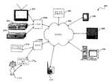
도 1은 본 발명의 실시예에 따른 예시적인 디바이스 제어 시스템(100)을 나타낸 것이다. 예시적인 디바이스 제어 시스템(100)이 단지 예시적인 목적으로 도시되어 있으며 본 발명을 제한하는 것이 아님을 잘 알 것이다. 예시적인 디바이스 제어 시스템(100)의 다른 구현은 본 명세서에 포함된 개시 내용에 기초하면 당업자에게는 자명할 것이며, 본 발명은 이러한 다른 구현들도 포함한다.1 illustrates an exemplary
도 1에 도시한 바와 같이, 예시적인 디바이스 제어 시스템(100)은 복수의 제어기(102a 내지 102n) 및 하나 이상의 전자 디바이스(104a 내지 104n)를 포함하며, 이들 각각은 네트워크(106)에 통신 연결되어 있다. 한 실시예에서, 네트워크(106)는 가정 내의 디바이스들을 통신 연결하기 위한 거주지 네트워크(residential network)를 포함한다. 이러한 실시예에 따르면, 네트워크(106)는 예를 들어 가정 전화선 네트워크, 가정 전력선 네트워크, 이더넷 네트워크, 무선 네트워크, 또는 이들의 임의의 조합을 포함할 수 있다. 그렇지만, 본 발명은 거주지 네트워크에 한정되지 않으며, 네트워크(106)는 근거리 통신망(LAN) 또는 인터넷 등의 원거리 통신망(WAN)(이에 한정되는 것은 아님)을 비롯한 임의의 유형의 거주지 또는 비거주지 네트워크를 포함할 수 있다.As shown in FIG. 1, example
전자 디바이스(104a 내지 104n) 각각은 거주지 및/또는 사무실 환경에서 사 용가능한 광범위한 원격 제어가능 전자 디바이스 중 하나를 포함할 수 있다. 예를 들어, 전자 디바이스(104a 내지 104n) 각각은 컴퓨터, 컴퓨터 주변 장치, 텔레비전(TV), 비디오 카세트 레코더(VCR), DVD(digital versatile disc) 플레이어, 개인 비디오 레코더(PVR), 컴팩트 디스크(CD) 플레이어, 스테리오 리시버(stereo receiver), 전자 온도 조절기, UPnP™ 디지털 미디어 렌더러(digital media renderer) 및/또는 서버, 램프 또는 비디오 카메라 중 하나를 포함할 수 있다. 그렇지만, 이들 예는 제한을 위한 것이 아니며, 기타의 전자 디바이스는 본 발명의 범위 및 정신 내에 속한다.Each of the
제어기(102a 내지 102n) 각각은 전자 디바이스(104a 내지 104n) 중 하나 이상을 원격 제어하도록 구성되어 있다. 상세하게는, 본 명세서에 보다 상세히 기술되는 바와 같이, 제어기(102a 내지 102n) 각각은 다양한 전자 디바이스(이들 각각은 서로 다른 제조업자 및/또는 모델 유형을 가질 수 있고 또 이들 각각은 원격 디바이스 제어를 위한 서로 다른 통신 프로토콜을 지원할 수 있음)를 제어하기 위한 사용자 구성가능한 범용 인터페이스를 제공한다.Each of
본 발명의 실시예에 따르면, 제어기(102a 내지 102n) 각각은 하나 이상의 전자 디바이스(104a 내지 104n)를 제어하기 위한 독립형 인터페이스(stand-alone interface)를 포함한다. 대체 실시예에서, 제어기(102a 내지 102n) 각각은 전자 디바이스 제어 기능을 수행하기 위해 네트워크(106)를 통해 제어기들 및 전자 디바이스(들)에 통신 연결되어 있는 선택적인 제어 서버(108)와 연계하여 동작한다. 거주지 또는 비거주지 환경에서 디바이스 및 애플리케이션의 원격 명령 및 제어를 제공하는 제어 서버, 제어기들 및 네트워크의 상세한 예는 공동 소유이고 동시 계류 중이며 2002년 6월 27일자로 출원된 발명의 명칭이 "제어된 거주지 또는 비거주지 환경을 제공하는 방법, 시스템, 및 컴퓨터 프로그램 제품(Method, System, and Computer Program Product for Managing Controlled Residential or Non-residential Environments)"인 미국 특허 출원 제10/180,500호에서 찾아볼 수 있으며, 이는 여기에 인용함으로써 그 전체 내용이 본 명세서에 포함된다.In accordance with an embodiment of the present invention, each of
도 2는 본 발명의 실시예에 따른 디바이스 제어 시스템(200)의 특정의 구현을 나타낸 것이다. 디바이스 제어 시스템(200)의 여러가지 구성요소는 공동 소유이고 동시 계류 중이며 2003년 3월 14일자로 출원된 발명의 명칭이 "거주지 또는 비거주지 네트워크를 위한 레거시 디바이스 브리지(Legacy Device Bridge for Residential or Non-Residential Networks)"인 Krzyzanowski 등의 미국 특허 출원 제10/387,590호에 보다 상세히 기술되어 있으며, 이는 여기에 인용함으로써 그 전체 내용이 본 명세서에 포함된다.2 illustrates a particular implementation of a
도 2에 도시한 바와 같이, 디바이스 제어 시스템(200)은 네트워크(202)(한 실시예에서 무선 LAN을 포함함)에 통신 연결되어 있는 복수의 전자 디바이스를 포함한다. 개인 휴대 정보 단말기(PDA)(206), 태블릿 PC(208), PC-기반 컴퓨터 시스템(210), 및 네트워크-지원(network-ready) 비디오 카메라(222) 등의 전자 디바이스는 TCP/IP 등의 패킷-기반 통신 프로토콜에 따른 통신에 적합하도록 구성되어 있다. TV(212), VCR 및 DVD 플레이어(214), 스테레오 리시버(216), 전자 온도 조절기(218), 및 램프(220) 및 연관된 조명 시스템 제어 인터페이스(226)를 비롯한 종 래의 가전 기기는 그렇게 구성되어 있지 않으며 통신을 위해 적외선(IR) 또는 직렬 통신 프로토콜에 의존해야만 한다. 레거시 디바이스 브리지(224a, 224b)는 패킷-기반 통신 프로토콜을 이용하는 디바이스들과 IR 또는 직렬 통신 프로토콜에 전적으로 의존하는 디바이스들 간의 통신을 용이하게 해주는 프로토콜 변환 기능을 수행한다.As shown in FIG. 2, the
도 2에서, PDA(206), 태블릿 PC(208), PC-기반 컴퓨터 시스템(210) 각각은 네트워크(202)에 연결된 다른 전자 디바이스들 중 하나 이상의 원격 제어하기 위한 제어기를 포함할 수 있다. 게다가, 본 발명의 실시예에 따르면, 복수의 PDA(206), 태블릿 PC(208), PC-기반 컴퓨터 시스템(210)은 네트워크(202)에 연결된 다른 전자 디바이스들 중 하나 이상에 대한 독립형 제어(stand-alone control)를 제공하는 데 사용될 수 있다. 다른 대안으로서, 이들 제어기는 원격 디바이스 제어 기능을 수행하기 위해 선택적인 제어 서버(204)와 연계하여 동작할 수 있다.In FIG. 2, each of
B. 본 발명의 실시예에 따른 제어기 구현B. Controller Implementation in accordance with an embodiment of the present invention
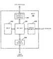
도 3은 본 발명의 실시예에 따른 제어기(102a 내지 102n)(또한 제어기(102)로서 전체적으로 말하기도 함) 중 하나의 예시적인 구현을 나타낸 것이다. 도 3에 나타낸 예시적인 구현이 단지 예시적인 목적으로 제공된 것이고 본 발명을 제한하는 것이 아님을 잘 알 것이다. 제어기(102)의 다른 구현들은 본 명세서에 포함된 개시 내용에 기초하면 당업자에게는 자명하게 될 것이며, 본 발명은 이러한 다른 구현예들도 포함한다.3 illustrates an exemplary implementation of one of the
도 3에 도시한 바와 같이, 제어기(102)는 사용자 입력을 수신하고 정보를 사 용자에게 제공하는 사용자 인터페이스(308), 네트워크에의 액세스를 제공하는 네트워크 인터페이스(306), 및 가전 기기(CE) 디바이스로 정보를 전송하고 선택적으로 그로부터 정보를 수신하는 선택적인 CE 디바이스 인터페이스를 포함한다. 한 실시예에서, 사용자 인터페이스(308)는 터치-감응 디스플레이를 통해 사용자 입력을 수신하는 그래픽 사용자 인터페이스(GUI)를 포함하고, 네트워크 인터페이스(306)는 IEEE 802.11b, 블루투스™ 또는 이더넷 프로토콜 등의 통신 프로토콜에 따른 네트워크 통신에 적합하도록 구성된 플러그-인 또는 내장형 송수신기를 포함하며, 선택적인 CE 디바이스 인터페이스(304)는 단방향 IR 송신기 또는 대안으로서 양방향 IR 송수신기를 포함한다.As shown in FIG. 3, the
도 3에 도시한 바와 같이, 제어기(102)는 사용자 인터페이스(308), 네트워크 인터페이스(306) 및 선택적인 CE 디바이스 인터페이스(304)에 통신 연결되어 있는 제어 로직(302)을 더 포함한다. 제어 로직(302)은 피어-투-피어 모드에서 동작하는 동안 하나 이상의 다른 제어기들과 동기화 프로토콜을 수행하는 것, 및 피어-투-피어 동작 모드에서 클라이언트-서버 동작 모드로의 마이그레이션과 관계된 기능들을 수행하는 것(이에 한정되는 것은 아님)을 비롯한 본 명세서에 보다 상세히 기술되어 있는 본 발명의 특징들을 실행하도록 구성되어 있다. 당업자라면 본 명세서에 제공된 개시 내용에 기초하여 잘 아는 바와 같이, 제어 로직(302)은 하나 이상의 다목적(multi-purpose) 프로세서(들), 주문형 반도체 또는 이들의 조합을 사용하여 용이하게 구현될 수 있다.As shown in FIG. 3, the
제어기(102)는 또한 제어 로직(302)에 통신 연결되어 있는 메모리(310)를 포 함한다. 일 실시예에서, 메모리(310)는 판독 전용 메모리(ROM) 등의 정적 메모리, 랜덤 액세스 메모리(RAM) 등의 동적 메모리, 하드 디스크 드라이브, 또는 이들의 임의의 조합을 포함할 수 있다. 본 발명의 실시예에 따르면, 메모리(310)는 제어 로직(302)에 의한 개별적인 실행 및 프로세싱을 위한 애플리케이션 및 데이터를 포함하는 복수의 소프트웨어 라이브러리를 저장하고 있다.
본 발명의 실시예에서, 제어기(102)는 PDA, 태블릿 컴퓨터, 웹-패드(web-pad), 또는 퍼스널 컴퓨터 중 하나를 포함하지만, 본 발명은 그에 한정되지 않는다.In an embodiment of the invention, the
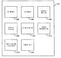
도 4는 본 발명의 실시예에 따른 메모리(310)에 저장될 수 있는 여러가지 소프트웨어 컴포넌트 또는 라이브러리를 개념적으로 나타낸 것이다. 도 4에 도시한 바와 같이, 이러한 컴포넌트는 운영 체제 펌웨어(402), 사용자 인터페이스 펌웨어(404), 디바이스 제어 데이터베이스(404), 디바이스 구성 데이터베이스(408), 시스템 구성 데이터베이스(410), 사용자 환경설정 데이터베이스(412), 제어기 동기화 소프트웨어(414), 및 이벤트 로그(416)를 포함한다. 이들 컴포넌트 각각에 대해 이하에서 설명한다.4 conceptually illustrates various software components or libraries that may be stored in
운영 체제 펌웨어(402)는 실행될 때 다른 제어기 애플리케이션이 실행될 수 있는 플랫폼을 제공하며, 제어기 입/출력(I/O) 및 파일 관리에 관한 기능 등의 기본적인 기능을 수행한다. 사용자 인터페이스 펌웨어(404)는 실행될 때 사용자 인터페이스(308)의 여러가지 프로그램가능 측면의 구현 및 관리를 제공한다.
디바이스 제어 데이터베이스(406)는 다양한 전자 디바이스를 원격 제어하기 위한 일련의 미리 정의된 명령 및 코드는 물론 이러한 디바이스의 고유의 제어 거동에 관한 메타데이터를 저장한다. 본 발명의 실시예에서, 제어기(102)는 디바이스 제어 데이터베이스(406)에 저장하기 위해 네트워크(106)를 통해 디바이스 명령 코드 및 메타데이터를 다운로드할 수 있다. 이러한 기능에 대한 상세한 설명은 2003년 9월 26일자로 출원된 발명의 명칭이 "디바이스 제어 시스템, 방법 및 장치(Device Control System, Method and Apparatus)"인 Krzyzanowski 등의 미국 가특허 출원 제60/505,851호에 제공되어 있으며, 이는 여기에 인용함으로써 그 전체 내용이 본 명세서에 포함된다. 이러한 명령 코드 및 메타데이터는 예를 들어 CD-ROM에 저장된 라이브러리로부터 획득될 수 있거나, 상기한 바와 같이 네트워크(106)를 통해 다운로드될 수 있거나 또는 최종 사용자와의 촉구된 상호작용을 통해 또는 경험(예를 들어, 종래의 사용자 제어 방법의 분석)에 의해 "학습"될 수 있다.The
소프트웨어 라이브러리(408, 410, 412)는 일반적으로 전체 디바이스 제어 시스템(100) 및 제어기(102)의 동작의 사용자-커스터마이즈된 또는 개인화된 측면에 관한 정보를 저장하는 데이터베이스를 포함한다. 상세하게는, 디바이스 구성 데이터베이스(408)는 디바이스 상태 및 다른 동작 정보를 비롯한, 디바이스 제어 시스템(100)의 일부로서 실제로 인식되는 디바이스에 관한 데이터를 포함한다.
시스템 구성 데이터베이스(410)는 사용자 인증, 위치 관리 및 디바이스 발견 등의 시스템 관리의 여러가지 측면에 관한 데이터를 포함한다. 사용자 인증 설정은 시스템 사용자가 디바이스를 제어하는 것을, 또는 특정 위치와 연관된 디바이스 들을 제어하는 것을 선택적으로 허용 또는 금지하는 데 사용될 수 있다. 위치 관리 데이터는 디바이스 제어 시스템(100) 내의 제어 구역 또는 하나 이상의 방에 디바이스를 할당하는 것 및 그의 정의에 관한 것이다. 디바이스 발견 데이터는 네트워크(106) 상의 디바이스의 존재를 검출하고 그에 관한 상태 정보를 유지하는 제어기(102)의 기능에 관계된 데이터이다. 예를 들어, 본 발명의 실시예에 따른 제어기(102)는 네트워크(106) 상에 나타나는 디바이스를 자동적으로 발견하고 그에 관한 상태 정보를 획득하기 위해 UPnP™ 프로토콜, 또는 독점적 프로토콜을 사용할 수 있다.
사용자 환경설정 데이터베이스(412)는 디바이스 제어 시스템(100) 내의 제어기(102) 및 피제어 디바이스의 동작에 관련한 여러가지 사용자-식별된 환경설정에 관한 데이터를 포함한다. 사용자 환경설정은 예를 들어 텔레비전 시청을 위한 선호 채널 또는 특정의 그래픽 사용자 인터페이스(GUI) 또는 제어기(102)에 대한 "스킨"을 포함할 수 있다.The
본 명세서에 보다 상세하게 기술하는 바와 같이, 제어기 동기화 소프트웨어(414) 및 이벤트 로그(416)는 이러한 제어기들이 독립형 모드 또는 피어-투-피어 모드에서 동작하고 있을 때 디바이스 제어 시스템(100) 내의 제어기(102)와 하나 이상의 다른 제어기들 간의 동기화를 보장하는 프로토콜을 수행하는 데 제어기(102)에 의해 사용된다. 게다가, 또한 본 명세서에 보다 상세히 기술되는 바와 같이, 이들 컴포넌트는 또한 제어기(102)와 다른 제어기들 간에 커스텀 구성 정보를 전송하는 수단은 물론 피어-투-피어 네트워크 환경으로부터 서버-기반 네트워크 환경으로 제어기(102)를 마이그레이션하는 수단을 제공할 수 있다.As described in more detail herein, the
C. 본 발명의 실시예에 따른 피어-투-피어 모드에서의 제어기 동기화C. Controller Synchronization in Peer-to-Peer Mode in accordance with an embodiment of the present invention
상기한 바와 같이, 디바이스 제어 시스템(100)에서, 다수의 제어기(102a 내지 102n)는 동일한 전자 디바이스들 중 하나 이상을 제어하기 위해 다수의 사용자에 의해 동작될 수 있다. 이들 제어기가 독립형 모드에서 동작되고 있을 때, 제어기들을 조정할 필요성이 있다. 다수의 제어기들의 동작을 조정하는 수단이 없는 경우, 제어 혼란이 야기되는데 그 이유는 각각의 제어기가 자율적으로 서로 독립적으로 동작하기 때문이다.As noted above, in the
예를 들어, 디바이스 제어 시스템(100)이 가정에 구현되어 있는 것으로 가정한다. 위층 방에 있는 제1 사용자는 제1 사용자가 켜진 채로 있는 것으로 생각하는 지하실에 있는 텔레비전을 끄기를 원한다. 제어기(102a)를 사용하여, 제1 사용자는 네트워크(106)를 통해 "전원 켜기/끄기" 신호를 지하실 텔레비전으로 전송한다. 그렇지만, 아마도 제어기(102b)를 사용하는 제2 사용자가 이미 꺼버렸기 때문에, 제1 사용자가 지하실 TV의 상태에 관하여 잘못 생각한 경우, 제1 사용자에 의해 전송된 "전원 켜기/끄기" 신호는 그 결과 TV를 켜게 되며, 이는 의도되었던 것과는 정반대의 효과를 갖는 동작이다.For example, assume that
따라서, 디바이스 제어 시스템(100)에서, 제어기(102a 내지 102n) 각각은 가정 또는 사무실 등의 통상의 제어 영역 내의 하나 이상의 전자 디바이스의 조정되고 효율적인 동작을 보장하기 위해 다른 제어기들과 통신하도록 구성되어 있다. 그 결과, 각각의 제어기는 다른 사용자들에 의해 동작되는 몇개의 제어기를 포함하 는 시스템에서 기능할 수 있다. 특정의 실시예에서, 각각의 제어기는 어떤 제어 환경에서 동작하는 다른 제어기들과의 직접 네트워크 연결을 가지며 이러한 다른 제어기들과 동기화한다.Thus, in
이 동기화를 수행하기 위해, 제어기(102a 내지 102n) 각각은 타임스탬프된 이벤트의 로그(416)(도 4 참조)를 유지한다. 각각의 이벤트는 어떤 시스템 상태의 부가, 수정 또는 삭제의 표기를 포함한다. 일 실시예에서, 전체적인 시스템 상태는 몇개의 서브카테고리로 분할된다. 이들 서브카테고리는 이하의 것을 포함할 수 있다.To perform this synchronization, each of
(1)사용자 설정: 사용자의 추가 또는 제거, 패스워드의 변경, TV 시청을 위한 선호 채널의 식별, 특정의 제어기 GUI(또는 "스킨")의 선택, 기타 등등(이에 한정되는 것은 아님)을 비롯한 사용자 정의 파라미터에 관한 상태 정보.(1)User settings : users, including but not limited to adding or removing users, changing passwords, identifying preferred channels for watching TV, selecting a particular controller GUI (or "skin"), and so forth. Status information about defining parameters.
(2)디바이스 모듈: 디바이스 템플릿, 디바이스 드라이버, 또는 디바이스 코드 데이터베이스에 대한 추가, 삭제 또는 변경(이에 한정되는 것은 아님)을 비롯한 특정의 디바이스에 대한 제어 파라미터에 관한 상태 정보(본 명세서에서 사용되는 바와 같이, 용어 "디바이스 템플릿"은 디바이스 거동에 관한 파라미터를 말하며, 용어 "디바이스 드라이버"는 상기한 바와 같이 특정의 디바이스와 통신하는 데 필요한 소프트웨어를 말하고, 디바이스 코드 데이터베이스는 IR 또는 직렬 코드 등의 디바이스에 대한 제어 코드 매핑을 포함함).(2)Devicemodule : status information about control parameters for a particular device, including but not limited to additions, deletions, or changes to device templates, device drivers, or device code databases, as used herein. As such, the term "device template" refers to a parameter relating to device behavior, and the term "device driver" refers to software required to communicate with a particular device as described above, and the device code database is associated with a device such as IR or serial code. Control code mapping).
(3)구성: 디바이스 방 할당, 방 정의, 디바이스 구성 및 연결에 대한 추가, 삭제 또는 변경(이에 한정되는 것은 아님)을 비롯한 커스터마이즈된 시스템 또는 디바이스 구성 파라미터에 관한 상태 정보.(3)Configuration : Status information regarding customized system or device configuration parameters, including but not limited to additions, deletions, or changes to device room assignments, room definitions, device configurations, and connections.
각각의 이벤트가 이벤트 로그(416)에 들어갈 때, 이는 이벤트가 일어난 시간을 가리키는 타임스탬프와 연관된다.As each event enters the
상태 변경은 본 발명에 따른 시스템이 동기화를 위해 추적하고 전달하는 이벤트를 말한다. 디바이스에 있어서, 이러한 상태 변경은 상태 변수, 제어 코드 및 디바이스 제어를 안내하는 스크립트에 대한 변경을 수반할 수 있다. 상태 변수는 입력 선택(예를 들어, 수신기는 DVD 플레이어로부터 입력을 수신하도록 설정될 수 있음), 온/오프 상태(예를 들어, TV는 온 상태일 수 있음), 또는 튜너 선택(예를 들어, TV는 채널 3으로 설정되어 있음)을 포함할 수 있다. 제어 코드는 가전 기기 디바이스의 원격 동작을 위한 IR 제어 코드 등의 구성된 디바이스를 제어하는 데 사용되는 그 코드를 말한다. 이들이 일반적으로 정적이지만, 이러한 코드는 디바이스가 시스템에 처음으로 도입될 때 제어기로 전달될 수 있으며, 또한 제어기가 일련의 특정 제어 코드를 재학습할 필요가 있을 때가 있다. 디바이스 제어를 안내하는 스크립트는 디바이스 기능을 정의하고 상태 변수를 추적하며 또 제어 코드를 적절한 제어 모듈로 전달하는(예를 들어, IR 코드를 특정의 레거시 디바이스 브리지로 전송하는) XML 스크립트 등의 스크립트를 말한다.State changes refer to events that the system according to the invention tracks and forwards for synchronization. For a device, this state change may involve changes to state variables, control codes, and scripts to guide device control. The state variable can be input selection (e.g., the receiver can be set to receive input from a DVD player), on / off state (e.g. TV can be on), or tuner selection (e.g. , TV is set to channel 3). The control code refers to the code used to control a configured device such as an IR control code for remote operation of the household appliance device. Although they are generally static, such code can be passed to the controller when the device is first introduced into the system, and there are also times when the controller needs to relearn a series of specific control codes. Scripts that guide device control include scripts such as XML scripts that define device functionality, track state variables, and pass control code to the appropriate control module (for example, sending IR code to a specific legacy device bridge). Say.
상태 변경은 또한 스크립트 정의 경험에 대한 변경을 수반할 수 있다. 예를 들어, 본 발명의 실시예에서, 경험(DVD를 시청하는 것 또는 CD를 청취하는 것 등) 내에서의 제어는 셋업 프로세스 동안에 행해지는 질문 및 대답 프로토콜 동안에 사용자의 응답에 기초하여 기본적인 템플릿으로부터 발생되는 스크립트, 또는 매크로 에 의해 정의된다. 예를 들어, DVD를 시청하는 것과 관련하여, 매크로 "ON"은 "TV 켜기", "DVD 플레이어 켜기", "리시버 켜기", "리시버를 DVD 입력으로 설정", 및 "TV를 비디오2 입력으로 설정"으로 정의될 수 있다. 이들 명령 각각은 매크로를 호출한 것에 응답하여 적절한 디바이스 스크립트로 전송된다.State changes can also involve changes to the script definition experience. For example, in an embodiment of the invention, control within the experience (such as watching a DVD or listening to a CD, etc.) may be derived from a basic template based on the user's response during the question and answer protocol made during the setup process. Defined by the script or macro generated. For example, with regards to watching DVDs, the macros "ON" can be used to "turn on TV", "turn on DVD player", "turn on receiver", "set receiver to DVD input", and "turn TV to video2 input". Setting ". Each of these commands is sent to the appropriate device script in response to calling the macro.
상태 변경은 또한 타이머, 예정된 동작, 트리거, 및 트리거된 동작에 대한 변경을 포함할 수 있다. 타이머, 또는 알람은 특정의 스크립트(예를 들어, 오후 11시에 TV 끄기)의 실행과 연관된 시간을 말한다. 관계된 스크립트 또는 예정된 동작은 알람 시간이 실제 시간과 같을 때 실행된다. 트리거는 상태 변수 변경과 특정의 스크립트의 실행과의 연관을 말한다(예를 들어, TV가 켜질 때마다 소등하기). 관계된 스크립트 또는 트리거된 동작은 모니터링된 상태 변수가 변할 때 실행된다. 본 발명에 따른 시스템에서, 타이머, 트리거, 및 관계된 스크립트는 사용자 프로그램가능 기능이다. 이러한 기능에 대한 상세한 설명은 본 출원과 동시에 출원된 발명의 명칭이 "제어된 환경 내에서 컴포넌트들을 자동적으로 관리하는 방법, 시스템 및 컴퓨터 프로그램 제품(Method, System, and Computer Program Product for Automatically Managing Components within a Controlled Environment)"인 Krzyzanowski 등의 미국 특허 출원 제호(대리인 문서 번호 2100.0030004)에 제공되어 있으며, 이는 여기에 인용함으로써 그 전체 내용이 본 명세서에 포함된다.State changes may also include changes to timers, scheduled actions, triggers, and triggered actions. A timer, or alarm, refers to the time associated with executing a particular script (eg, turning off the TV at 11 pm). The related script or scheduled action is executed when the alarm time is equal to the actual time. A trigger is an association between changing a state variable and executing a particular script (for example, turning off the TV every time it is turned on). The related script or triggered action is executed when the monitored state variable changes. In the system according to the invention, the timers, triggers, and related scripts are user programmable functions. A detailed description of these functions is provided in the context of the present invention, entitled "Method, System, and Computer Program Product for Automatically Managing Components within a Controlled Environment." U.S. Patent Application by Krzyzanowski, et al. (Attorney Docket No. 2100.0030004), which is incorporated herein by reference in its entirety.
상태 변경은 또한 사용자, 방, 및 방 내의 디바이스의 정의, 사용자의 방 및 디바이스에 대한 접근 권한, 및 사용자 인터페이스(때때로 "스킨"이라고 함)를 정 의하는 비트맵 및 화면 레이아웃의 모음 등의 여러가지 구성 파라미터에 대한 변경을 포함할 수 있다.State changes also include a collection of bitmaps and screen layouts that define the user, the room, and the devices within the room, the user's access to the room and devices, and the user interface (sometimes called a "skin") May include changes to configuration parameters.
도 5는 본 발명의 일 실시예에 따른 디바이스 제어 시스템에서 제어기들을 동기화하는 방법의 플로우차트(500)를 나타낸 것이다. 그렇지만, 본 발명은 플로우차트(500)에 의해 제공되는 설명으로 한정되지 않는다. 오히려, 다른 기능적 흐름이 본 발명의 범위 및 정신 내에 속함이 본 명세서에 제공된 개시 내용으로부터 당업자에게는 자명할 것이다. 플로우차트(500)는 도 1을 참조하여 상기한 예시적인 시스템(100)을 계속 참조하여 기술될 것이다. 그렇지만, 본 발명은 이 실시예에 한정되지 않는다.5 shows a
최초 단계(502)에서, 사용자는 제어기(102a)의 전원을 켠다. 전원이 켜진 것에 응답하여, 제어기(102a)는 초기 발견 프로토콜(504)를 수행하고, 제어기(102a)는 이 프로토콜에 의해 디바이스 제어 시스템(100) 내에 활성인 다른 제어기가 있는지를 결정한다. 이 발견 프로토콜을 구현하는 적어도 하나의 방식이 본 명세서의 다른 곳에서 제공될 것이다.In an
이용가능한 다른 제어기가 있는 경우, 제어기(102a)는 이용가능한 제어기들 중 하나와 동기화 프로토콜(506)을 수행한다. 동기화 단계(506)는 제어기(102a)가 상태 정보를 수신하거나 디바이스 제어 시스템(100) 내의 다른 제어기와 그 상태 정보를 교환하는 것에 의해, 그의 이벤트 로그를 포함한 그의 내부에 저장된 상태를 갱신하는 프로세스이다. 동기화 단계(506)를 수행하는 프로토콜은 본 명세서에서 다른 곳에 제공되어 있다. 실제적으로 말하면, 2개 이상의 다른 제어기가 이용 가능한 경우, 동기화 단계(506)를 수행하기 위해 그 다른 제어기들 중 어느 것이 선택되는가는 중요하지 않다. 따라서, 다른 제어기는 임의적으로 선택될 수 있다. 다른 대안으로서, 다른 제어기는 어떤 다른 기준에 따라 선택될 수 있다. 예를 들어, 다른 제어기는 다른 제어기와 통신하기 위한 예상된 응답 시간 등의 네트워크 연결에 관계된 어떤 파라미터에 기초하여 선택될 수 있다.If there is another controller available, the
동기화(506) 후에, 제어기(102a)는 제어기(102a)의 전원을 끄는 때가 단계(524)에서 행해질 때까지 있는 경우 어느 다른 제어기가 시스템 상에서 현재 이용가능한지를 결정하는 발견 단계(508)를 주기적으로 수행한다. 본 발명의 실시예에 따르면, 제어기(102a 내지 120n) 각각은 모든 기지의 피어(즉, 다른 제어기)의 메모리 내에 테이블을 유지하고 있다. 각각의 피어에 대해, 제어기는 그 피어와의 마지막 동기화 시간은 물론 현재의 연결 정보를 저장한다. 예를 들어, 현재의 연결 정보는 IP 주소 등의 피어에 대한 네트워크 주소, 마지막 발견의 시간, 및 최근의 발견 시도가 이 디바이스가 이용가능한 것으로 결정하였는지 여부의 표시를 포함할 수 있다.After
도 5에 나타낸 바와 같이, 주기적인 발견 시도(단계 508) 사이에, 적어도 4개의 다른 이벤트가 일어날 수 있다. 즉, 제어기(102a)는 하나 이상의 상태 변경을 발생할 수 있거나(단계 510), 제어기(102a)는 다른 제어기로부터 하나 이상의 상태 변경을 수신할 수 있거나(단계 515), 제어기(102a)는 다른 제어기에 대한 동기화 요청을 수신할 수 있거나(단계 516), 또는 제어기(102a)는 전원이 꺼질 수 있다(단계 522).As shown in FIG. 5, at least four different events may occur between periodic discovery attempts (step 508). That is, the
제어기(102a)는 사용자가 제어기를 사용하여 제어기의 내부 구성을 변경하거나 원격 제어되는 전자 디바이스(104a 내지 104n)의 구성을 변경하는 것의 결과로서 하나 이상의 상태 변경을 발생할 수 있다(단계 510). 제어기는 또한 특정의 이벤트의 발생 또는 어떤 미리 정의된 일자 및 시간에 도달하는 것 등에 응답하여 그의 구성 또는 원격 제어되는 전자 디바이스의 구성을 자동적으로 변경하도록 프로그램될 수 있다. 어느 경우든지, 단계(512)에 나타낸 바와 같이, 이벤트 로그(416)가 갱신되고, 상태 변경 정보는 디바이스 제어 시스템(100) 내의 모든 이용가능한 제어기로 전송된다. 일 실시예에서, 상태 변경 정보의 전송은 이벤트 로그(416)로부터의 엔트리의 전송을 포함한다. 이 단계의 결과, 상태 변경이 행해진 이후 곧 다른 이용가능한 제어기의 상태가 제어기(102a)와 동기화된다.The
제어기(102a)는 또한 디바이스 제어 시스템(100) 내의 다른 활성 제어기로부터 상태 변경 정보를 수신할 수 있다(단계 514). 이 상태 변경 정보는 다른 제어기 또는 공통 제어된 전자 디바이스에 적용된 구성 변경에 관계될 수 있다. 어느 경우든지, 단계(516)에 나타낸 바와 같이, 제어기(102a)는 이러한 수신된 정보에 기초하여 그의 이벤트 로그(416)를 갱신한다. 일 실시예에서, 상태 변경 정보의 수신은 다른 제어기의 이벤트 로그로부터의 엔트리의 수신을 포함한다.
제어기(102a)는 또한 최근에 전원이 켜진 활성 제어기 등의, 디바이스 제어 시스템(100) 내의 다른 활성 제어기로부터 동기화 요청을 수신할 수 있다(단계 518). 이 경우에, 단계(520)에 나타낸 바와 같이, 제어기(102a)는 다른 제어기와 동기화 프로토콜을 수행하게 되며, 이에 대한 구현은 본 명세서에서 보다 상세히 기술되어 있다.
제어기(102a)는 또한 언제라도 전원이 꺼질 수 있다(단계 522). 전원 끄기는 사용자에 의해, 장기간의 비활성에 응답하여 전원을 끄기 위한 코드 등의 내부 제어 로직에 의해, 또는 시스템 전반적인 전원 끄기 또는 리셋 명령을 발행할 수 있는 네트워크-연결 디바이스 등의 다른 디바이스에 의해 개시될 수 있다. 어느 경우든지, 이 결과 제어기(102a)는 전원 꺼짐 상태에 들어가며(단계 524), 그에 의해 동기화 프로토콜(500)을 종료한다.
도 6은 도 5를 참조하여 상기한 발견 단계(504, 508)를 수행하는 한 방법의 플로우차트(600)를 나타낸 것이다. 이 방법은 단지 예로서 제공된 것이며, 제한하는 것이 아니다. 이 방법은 단계(602)에서 개시된다. 단계(604)에서, 제어기(102a)는 네트워크(106)를 통해 하나 이상의 제어기로 질의 메시지를 전송한다. 일 실시예에서, 제어기(102a)는 네트워크에 걸쳐 질의 메시지를 브로드캐스트한다. 단계(606)에서, 제어기(102a)는 활성이고 네트워크(106)에 통신 연결되어 있는 다른 제어기로부터 응답을 수신하기 위해 미리 정해진 양의 시간 동안 기다린다. 단계(608)에서, 제어기는 있는 경우 단계(606) 동안에 수신된 응답에 기초하여 제어기 이용가능성에 관한 내부에 저장된 데이터를 갱신한다(단계 608). 본 발명의 일 실시예에서, 제어기(102a)는 모든 기지의 피어의 내부에 저장된 테이블 내의 이용가능성 데이터를 갱신하는 것에 의해 이 단계를 수행한다. 단계(610)에서, 발견 프로토콜이 종료된다.FIG. 6 shows a
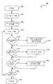
도 7은 도 5의 단계(504, 520)를 참조하여 상기 언급한 동기화 프로토콜을 수행하는 한 방법의 플로우차트(700)를 나타낸 것이다. 본 명세서에 기술된 것 등의 동기화 프로토콜은 상태 변경 정보를 수신하는 데 이용가능하지 않은 제어기를 처리하는 데 필요한데, 왜냐하면 이러한 상태 변경 정보가 전송되고 있을 때 이들이 전원이 꺼져 있거나 다른 방식으로 네트워크(106)로부터 분리되어 있기 때문이다. 당업자라면 본 명세서에 제공된 개시 내용에 기초하여 잘 알게 될 것인 바와 같이, 프로토콜(700)에 따라 동기화하는 기능은 각각의 제어기가 동기화된 클럭을 갖는 것에 부분적으로 의존한다. 제어기들 간에 클럭 스큐가 있는 경우, 이것은 연결 시에 보상될 수 있다.FIG. 7 illustrates a
플로우차트(700)의 방법은 제1 제어기(102a) 및 제2 제어기(102b)를 참조하여 기술될 것이며, 여기서는 제어기(102a)가 동기화를 요청하였다. 상기한 바와 같이, 일 실시예에서, 제어기(102a)는 전원이 켜진 후 곧 동기화를 요청한다.The method of
동기화는 단계(702)에서 개시된다. 단계(704)에서, 제1 제어기(102a)는 제어기(102b)와의 마지막 동기화 이래로 발생했던 하나 이상의 이벤트 또는 상태 변경에 관한 정보를 제2 제어기(102b)로 전송한다. 일 실시예에서, 이 단계는 제어기(102b)와의 마지막 동기화 이래로 제어기(102a)에 의해 기록되어 있는 모든 이벤트의 로그를 전송하는 단계를 수반한다. 단계(706)에서, 제1 제어기(102a)는 제어기(102a)와의 마지막 동기화 이래로 발생했던 하나 이상의 이벤트에 관한 정보를 제2 제어기(102b)로부터 수신한다. 일 실시예에서, 이 단계는 제어기(102a)와의 마지막 동기화 이래로 발생했던 제어기(102b)에 의해 기록되어 있는 모든 이벤트의 로그를 수신하는 단계를 수반한다. 대부분의 경우에, 제어기들 간의 상기 대화는 단방향인 것으로 예상되는데, 그 이유는 전원이 꺼져 있는 제어기는 보고할 어떤 상태 변경도 가지고 있지 않기 때문이다.Synchronization begins at
일 실시예에서, 제어기들 간에 교환되는 이벤트 로그는 로그로부터의 중복하는 동작의 생략을 통해 각각의 제어기에 의해 최적화된다. 예를 들어, 어떤 TV가 켜져 있음을 나타내는 제1 엔트리 및 동일한 TV가 꺼져 있음을 나타내는 제2 엔트리를 로그가 포함하고 있는 경우, 전자의 엔트리는 불필요하고 따라서 로그로부터 삭제된다.In one embodiment, event logs exchanged between controllers are optimized by each controller through the elimination of redundant actions from the logs. For example, if the log contains a first entry indicating that a TV is on and a second entry indicating that the same TV is off, the former entry is unnecessary and thus deleted from the log.
단계(708)에서, 제어기(102a)는 제어기(102b)로부터 어떤 이벤트라도 수신되었는지를 결정한다. 어떤 이벤트도 수신되지 않은 경우, 동기화 프로토콜은 단계(722)에서 종료한다. 그렇지만, 하나 이상의 이벤트가 수신된 경우, 단계(710)에 나타낸 바와 같이, 제어기(102a)는 수신된 이벤트를 검사한다. 이어서, 제어기(102a)는 수신된 이벤트가 임의의 이전에 로그된 이벤트와 상충하는지를 결정한다. 제어기(102a)만이 전원이 꺼져 있고 제어기(102b)가 시스템 상태의 관점에서 완전히 사용가능한 상황에서, 어떤 상충도 발생하지 않으며 모든 수신된 엔트리가 접수될 것으로 예상된다.In
그렇지만, 양쪽 제어기 모두가 새로운 상태 변경을 발생하였고 다른 방식으로 동기화할 수 없는 경우 상충이 발생할 수 있다. 예를 들어, 제어기(102b)가 전원이 꺼져 있는 동안 제어기(102a)는 특정의 디바이스에 대한 특정의 사용자 접근을 허여하는 데 사용될 수 있다. 이어서, 제어기(102a)는 전원이 꺼질 수 있고, 제어기(102b)는 전원이 켜지며 동일한 디바이스에 액세스하고 그를 제어하기 위해 동일한 또는 다른 사용자에 의해 사용될 수 있다. 이러한 상황은 비동기화된 제어기(102a, 102b) 간의 상충을 야기하게 된다. 이러한 것 등의 상충이 발생하는 경우, 보다 최근의 타임스탬프와 연관된 이벤트가 우월하다. 따라서, 예를 들어, 제어기(102a)가 어떤 TV의 상태가 9:42:30에 "온"으로 설정되었음을 반영하는 새로운 로그 엔트리를 포함하고 제어기(102b)가 동일 TV의 상태가 9:59:10에 "오프"로 설정되었음을 반영하는 새로운 로그 엔트리를 포함하고 있는 경우, 제어기(102a)는 제어기(102b)로부터 상태 변경을 접수하지만, 제어기(102b)는 제어기(102a)로부터의 변경을 거부하며, 그 결과 상호 일관된 상태가 얻어진다.However, conflicts can occur if both controllers have made new state changes and cannot otherwise synchronize. For example,
이 기능은 단계(712)에 나타내어져 있으며, 여기서 제어기(102a)는 수신된 이벤트가 이전에 로그된 이벤트와 상충하는지를 결정한다. 그렇지 않은 경우, 제어기(102a)는 단계(716)에 나타낸 바와 같이 수신된 이벤트를 접수하고 상태 변경 정보를 그의 이벤트 로그(416)에 넣는다. 상충이 식별되는 경우, 단계(714)에 나타낸 바와 같이, 제어기(102a)는 이전에 로그된 이벤트가 수신된 이벤트보다 늦은 타임스탬프와 연관되어 있는지를 결정한다. 그러한 경우, 단계(716)에 나타낸 바와 같이, 제어기(102a)는 수신된 이벤트를 접수한다. 그렇지 않은 경우, 단계(718)에 나타낸 바와 같이, 제어기(102b)는 수신된 이벤트를 접수하지 않는다.This function is shown in
본 발명의 일 실시예에 따르면, 단계(716)에 나타낸 바와 같이 상태 변경 정보를 접수하는 단계는 또한 상태 변수 변경의 적용은 물론 여러가지 사용자 설정, 디바이스 모듈, 또는 제어기/디바이스/시스템 구성의 추가, 삭제 또는 수정을 포함할 수 있다. 일 실시예에서, 제어기(102a)의 사용자는 임의의 이러한 추가, 삭제 또는 수정을, 이들이 적용되기 이전에 확인하도록 촉구될 수 있다.In accordance with one embodiment of the present invention, accepting state change information as shown in
수신된 이벤트가 단계(716)에서 접수되거나 단계(718)에서 거부된 후에, 제어기(102a)는 단계(720)에 나타낸 바와 같이 분석할 수신된 이벤트가 더 있는지를 결정한다. 있는 경우, 단계(710)에서 프로토콜은 그 다음의 수신된 이벤트의 분석을 계속한다. 그렇지 않은 경우, 단계(722)에 나타낸 바와 같이, 동기화 프로토콜이 종료된다.After the received event is received at
상기한 프로토콜에 관하여, 유의할 점은 제어기(102a)가 기록된 이전의 동기화 시간을 갖지 않는 또는 제어기(102b)로부터 수신된 이벤트의 각각과 연관된 타임스탬프보다 앞선 것인 이전의 동기화 시간을 갖는 새로 도입된 유닛을 포함할 수 있다는 것이다. 일 실시예에서, 이 상황은 수신된 이벤트 로그를 완전히 무시하고 그 대신에 전체적인 구성 상태를 제어기(102b)로부터 제어기(102a)로 전달하는 것에 의해 처리된다.With regard to the above protocols, it should be noted that the new introduction has a previous synchronization time, in which the
상기한 동기화 프로토콜을 통해, 디바이스 제어 시스템(100) 내의 각각의 제어기(102a 내지 102n)는 디바이스 상태 정보를 갱신하고 공통 제어 영역 내의 여러가지 전자 디바이스(104a 내지 104n)의 현재 상태를 그의 각자의 사용자에게 알려줄 수 있다.Through the synchronization protocol described above, each
게다가, 본 발명의 동기화 방법은 또한 제어기가 디바이스 제어 데이터베이스 정보를 갱신할 수 있도록 해주는 데 사용될 수 있다. 예를 들어, 사용자가 새로운 제어기를 추가하거나 이전의 제어기를 새로운 제어기로 교체하기를 원하는 경우, 새로운 제어기는 제어 환경 내의 전자 디바이스들을 제어하도록 용이하게 구성 될 수 있다. 구체적으로는, 기존의 제어기의 데이터베이스는 본 발명의 실시예에 따른 동기화 동작을 구현함으로써 무선 네트워크 등의 네트워크를 통해 새로운 제어기로 전송될 수 있다.In addition, the synchronization method of the present invention may also be used to allow a controller to update device control database information. For example, if a user wants to add a new controller or replace an old controller with a new controller, the new controller can be easily configured to control the electronic devices in the control environment. Specifically, the database of the existing controller can be transmitted to the new controller through a network such as a wireless network by implementing a synchronization operation according to an embodiment of the present invention.
본 발명의 일 실시예에 따르면, 동기화 프로토콜은 또한 실행가능 코드를 포함하는 디바이스 제어 라이브러리 등의 디바이스 제어 라이브러리를 한 제어기로부터 다른 제어기로 전달하는 데 사용될 수 있다. 이러한 기능은 자바-기반 시스템에서 특히 유용할 수 있다.According to one embodiment of the present invention, a synchronization protocol may also be used to transfer a device control library, such as a device control library containing executable code, from one controller to another. This feature can be particularly useful in Java-based systems.
D. 본 발명의 일 실시예에 따른 피터-투-피어 모드에서 클라이언트-서버 모드로의 마이그레이션D. Migration from Peter-to-Peer Mode to Client-Server Mode According to One Embodiment of the Present Invention
본 발명의 실시예에 따르면, 제어기(102)는 독립형 모드에서 클라이언트-서버 환경으로 마이그레이션될 수 있으며, 이 클라이언트-서버 환경에서 이 제어기 및 다른 이러한 제어기는 필수적인 동작 펌웨어 및 데이터베이스를 저장하고 있는 제어 서버(108)에 대한 클라이언트 또는 사용자 인터페이스로서 기능한다.According to an embodiment of the present invention, the
제어 서버(108)가 네트워크(106)에 추가되는 경우, 제어기(102)의 데이터베이스는 제어 서버(108)와 동기화될 수 있고 그에 따라 제어기(102)(이제 클라이언트임) 상의 갱신된 데이터가 제어 서버(108)의 대응하는 데이터베이스에 추가될 수 있게 된다. 클라이언트-서버 동작 모드에서, 각각의 제어기(102a 내지 102n)는 제어 서버(108)에 대한 사용자 인터페이스로서 기능한다. 예를 들어, 각각의 제어기(102a 내지 102n)는 실행을 위해 제어 서버(108)로 사용자의 제어 요청을 전달하고 제어 서버(108)로부터 GUI 정보를 얻는다.When the
이전 섹션에서 기술한 발견 프로세스의 일부로서, 제어기(102)는 네트워크(106) 상의 제어 서버(108)의 존재를 발견할 수 있다. 이것은 인프라가 피어-투-피어 환경에서 클라이언트-서버 환경으로 마이그레이션했다는 표시이다. 이 모드에서, 제어기(102)는 대체로 사용자 인터페이스 단말기로서 기능하며, 모든 사용자 및 디바이스 구성 정보, 디바이스 제어 모듈 및 상태 변수가 제어 서버(108) 상에 저장되어 있다.As part of the discovery process described in the previous section, the
제어기(102)가 처음으로 제어 서버(108)를 검출할 때, 제어기(102)는 그의 구성 데이터의 전부 또는 그 일부를 제어 서버(108)로 전송해야 할지 여부를 결정해야만 한다. 이것은 이전의 섹션에서 기술한 동기화 프로토콜과 유사한 프로토콜을 사용하여 달성될 수 있다. 제어기(102) 및 제어 서버(108)가 이전에 동기화된 경우, 제어기(102)는 그 동기화 때 이래로 로그되었던 이벤트만을 전송한다. 제어기(102) 및 제어 서버(108)가 동기화된 적이 없는 경우, 제어기(102)는 그의 전체적인 구성을 제어 서버(108)로 전송한다. 이 프로세스는 단방향이다. 즉, 제어 서버(108)는 어떤 갱신도 제어기(102)로 전송하지 않는다. 동기화가 완료된 후에, 제어기(102)는 그의 구성을 무효로 하고 클라이언트-서버 모드로 전환하며, 이 경우 제어기(102)는 어떤 정보를 얻기 위해 또는 어떤 명령을 전송하기 위해 제어 서버(108)와 접촉하게 된다.When
상기한 실시예에서, 독립형 모드에서 클라이언트-서버 환경으로의 마이그레이션은 네트워크(106) 상에서 제어 서버(108)의 존재가 검출될 때 자동적으로 개시된다. 그렇지만, 대체 실시예에서, 마이그레이션의 개시는 자동적인 것과는 반대 로 사용자-촉구된다. 이러한 실시예는 제어 서버가 네트워크 상에서 검출될 때에도 사용자가 피어-투-피어 동작을 유지하기를 더 원하는 상황에 대응한다. 그 결과, 피어-투-피어 환경은 제어 서버가 네트워크 상에 존재하는 경우에도 존재할 수 있다. 마이그레이션 프로세스의 사용자-촉구된 제어는 네트워크(106)에 통신 연결된 제어기 또는 다른 디바이스에 하나 이상의 명령을 입력하는 단계를 포함할 수 있다. 일 실시예에서, 사용자는 사용자가 서버-기반 시스템으로 전환하기로 결정할 때까지 시스템에 대해 제어 서버를 단지 무시하도록 촉구한다.In the above embodiment, the migration from the standalone mode to the client-server environment is initiated automatically when the presence of the
대체 실시예에서, 사용자는 피어-투-피어 동작을 유지하기 위해 피어-투-피어 환경으로부터 서버-기반 환경으로의 자동적으로 개시된 마이그레이션 프로세스를 종료하는 기능을 제공받는다.In an alternate embodiment, the user is provided with the ability to terminate the automatically initiated migration process from the peer-to-peer environment to the server-based environment to maintain peer-to-peer operation.
본 발명의 다른 실시예에 따르면, 하나 이상의 제어기(102)도 역시 상기한 환경 등의 클라이언트-서버 환경으로부터 피어-투-피어 또는 독립형 모드로 마이그레이션될 수 있다. 이러한 실시예에서, 제어 서버(108)는 제어 서버(108)가 네트워크(106)로부터 제거되거나 다른 방식으로 제어기들에 이용가능하지 않게 되기 이전에 동기화를 위해 제어기 중 적어도 하나로 상태 변경 데이터를 다운로드하도록 구성되어 있다. 상태 변경 데이터를 수신하는 제어기는 이어서 상태 변경 데이터를 모든 다른 제어기로 전송하기 위해, 본 명세서의 다른 곳에서 기술한 프로토콜 등의 피어-투-피어 동기화 프로토콜에 관여하도록 구성된다. 이러한 시스템을 구현하기 위해, 각각의 제어기가 다운로드된 데이터를 수신 및 사용하기 위해 적절한 메모리를 비롯한 충분한 용량을 갖는 것으로 가정된다.According to another embodiment of the present invention, one or
E. 결론E. Conclusion
본 발명의 여러가지 실시예에 대해 이상에 기술되어 있지만, 이들이 단지 예로서 제공된 것이고 제한이 아님을 잘 알 것이다. 당업자라면 형태 및 상세에 있어서 여러가지 변경이 첨부된 청구항에 정의된 본 발명의 정신 및 범위를 벗어나지 않고 그 안에서 행해질 수 있음을 잘 알 것이다. 따라서, 본 발명의 폭 및 범위는 상기한 예시적인 실시예 중 어느 것에 의해서도 제한되어서는 안되며 이하의 청구항 및 그의 균등물에 따라서만 정의되어야 한다.While various embodiments of the invention have been described above, it will be appreciated that these are provided by way of example only and not limitation. Those skilled in the art will appreciate that various changes in form and detail may be made therein without departing from the spirit and scope of the invention as defined in the appended claims. Accordingly, the breadth and scope of the present invention should not be limited by any of the above-described exemplary embodiments, but should be defined only in accordance with the following claims and their equivalents.
Claims (96)
Translated fromKoreanApplications Claiming Priority (4)
| Application Number | Priority Date | Filing Date | Title |
|---|---|---|---|
| US53321903P | 2003-12-31 | 2003-12-31 | |
| US60/533,219 | 2003-12-31 | ||
| US10/782,764US7154862B2 (en) | 2003-12-31 | 2004-02-23 | Device control system, method, and apparatus for server-based or peer-to-peer network environments |
| US10/782,764 | 2004-02-23 |
Related Child Applications (1)
| Application Number | Title | Priority Date | Filing Date |
|---|---|---|---|
| KR1020087028734ADivisionKR20090005216A (en) | 2003-12-31 | 2004-09-02 | Device control system, method and apparatus for server-based or peer-to-peer network environment |
Publications (2)
| Publication Number | Publication Date |
|---|---|
| KR20060130635A KR20060130635A (en) | 2006-12-19 |
| KR100884142B1true KR100884142B1 (en) | 2009-02-17 |
Family
ID=34704357
Family Applications (2)
| Application Number | Title | Priority Date | Filing Date |
|---|---|---|---|
| KR1020067015299AExpired - Fee RelatedKR100884142B1 (en) | 2003-12-31 | 2004-09-02 | Device control system, method and apparatus for server-based or peer-to-peer network environment |
| KR1020087028734AWithdrawnKR20090005216A (en) | 2003-12-31 | 2004-09-02 | Device control system, method and apparatus for server-based or peer-to-peer network environment |
Family Applications After (1)
| Application Number | Title | Priority Date | Filing Date |
|---|---|---|---|
| KR1020087028734AWithdrawnKR20090005216A (en) | 2003-12-31 | 2004-09-02 | Device control system, method and apparatus for server-based or peer-to-peer network environment |
Country Status (6)
| Country | Link |
|---|---|
| US (3) | US7154862B2 (en) |
| EP (2) | EP1700424B1 (en) |
| JP (3) | JP2007518165A (en) |
| KR (2) | KR100884142B1 (en) |
| CA (2) | CA2733815C (en) |
| WO (1) | WO2005067441A2 (en) |
Families Citing this family (92)
| Publication number | Priority date | Publication date | Assignee | Title |
|---|---|---|---|---|
| US7127305B1 (en) | 2003-07-21 | 2006-10-24 | Eyecon Technologies, Inc. | Method and apparatus for unified control of multiple devices |
| JP4347082B2 (en)* | 2004-02-23 | 2009-10-21 | 日本電気株式会社 | Time correction device, time correction method, and time correction program for event trace data |
| US20190278560A1 (en) | 2004-10-27 | 2019-09-12 | Chestnut Hill Sound, Inc. | Media appliance with auxiliary source module docking and fail-safe alarm modes |
| US8090309B2 (en) | 2004-10-27 | 2012-01-03 | Chestnut Hill Sound, Inc. | Entertainment system with unified content selection |
| US7885622B2 (en) | 2004-10-27 | 2011-02-08 | Chestnut Hill Sound Inc. | Entertainment system with bandless tuning |
| US20060123016A1 (en)* | 2004-12-02 | 2006-06-08 | International Business Machines Corporation | Metadata driven method and apparatus to configure heterogenous distributed systems |
| FR2879056B1 (en)* | 2004-12-07 | 2007-04-20 | Thales Sa | METHOD OF DUPLICATING A DATABASE IN A MACHINE NETWORK AND A SYSTEM OF DUPLICATED DATA MACHINERY |
| US8689572B2 (en)* | 2004-12-22 | 2014-04-08 | Emerson Electric Co. | Climate control system including responsive controllers |
| US8438633B1 (en) | 2005-04-21 | 2013-05-07 | Seven Networks, Inc. | Flexible real-time inbox access |
| US7970017B2 (en)* | 2005-07-13 | 2011-06-28 | At&T Intellectual Property I, L.P. | Peer-to-peer synchronization of data between devices |
| US7778262B2 (en)* | 2005-09-07 | 2010-08-17 | Vantage Controls, Inc. | Radio frequency multiple protocol bridge |
| US20070094071A1 (en)* | 2005-10-21 | 2007-04-26 | Microsoft Corporation | Pushing content to browsers |
| KR100750160B1 (en)* | 2006-01-25 | 2007-08-17 | 삼성전자주식회사 | Method and apparatus for reserving function of device on JPNP |
| KR100782858B1 (en)* | 2006-04-11 | 2007-12-06 | 삼성전자주식회사 | Method and apparatus for synchronizing contents of home network devices |
| US20080002758A1 (en)* | 2006-06-28 | 2008-01-03 | Infineon Technologies Ag | Communications device and method for changing utilization data |
| KR20080006399A (en)* | 2006-07-12 | 2008-01-16 | 삼성전자주식회사 | A host terminal providing detailed information of the device, a method of providing detailed information thereof, and a device receiving detailed information from the host terminal |
| KR100772412B1 (en)* | 2006-07-18 | 2007-11-01 | 삼성전자주식회사 | Home control network control device and method |
| US20080079575A1 (en)* | 2006-09-29 | 2008-04-03 | Sensormatic Electronics Corporation | Distributed radio frequency identification reader and method therefore |
| US7760767B2 (en)* | 2007-01-05 | 2010-07-20 | Apple Inc. | Wide area peer-to-peer synching in a decentralized environment |
| US7738503B2 (en)* | 2007-02-02 | 2010-06-15 | Palm, Inc. | Multi-way, peer-to-peer synchronization |
| US20100106262A1 (en)* | 2007-02-12 | 2010-04-29 | Koninklijke Philips Electronics N.V. | Device for a networked control system |
| US8352450B1 (en)* | 2007-04-19 | 2013-01-08 | Owl Computing Technologies, Inc. | Database update through a one-way data link |
| US8077614B2 (en)* | 2007-12-05 | 2011-12-13 | At&T Intellectual Property I, L.P. | Synchronizing wireless local area network access points |
| US8595336B1 (en) | 2008-02-01 | 2013-11-26 | Wimm Labs, Inc. | Portable universal personal storage, entertainment, and communication device |
| US8019838B2 (en)* | 2008-05-21 | 2011-09-13 | Motorola Solutions, Inc. | Autonomous operation of networking devices |
| US8010487B2 (en)* | 2008-06-27 | 2011-08-30 | Microsoft Corporation | Synchronization and collaboration within peer-to-peer and client/server environments |
| US8713697B2 (en) | 2008-07-09 | 2014-04-29 | Lennox Manufacturing, Inc. | Apparatus and method for storing event information for an HVAC system |
| US8326954B2 (en)* | 2008-07-23 | 2012-12-04 | Caterpillar Inc. | System and method for synchronizing configurations in a controller network |
| US9335761B2 (en)* | 2008-09-30 | 2016-05-10 | Rockwell Automation Technologies, Inc. | Procedure classification for industrial automation |
| US8527096B2 (en) | 2008-10-24 | 2013-09-03 | Lennox Industries Inc. | Programmable controller and a user interface for same |
| US8725298B2 (en) | 2008-10-27 | 2014-05-13 | Lennox Industries, Inc. | Alarm and diagnostics system and method for a distributed architecture heating, ventilation and conditioning network |
| US8560125B2 (en) | 2008-10-27 | 2013-10-15 | Lennox Industries | Communication protocol system and method for a distributed-architecture heating, ventilation and air conditioning network |
| US8452456B2 (en) | 2008-10-27 | 2013-05-28 | Lennox Industries Inc. | System and method of use for a user interface dashboard of a heating, ventilation and air conditioning network |
| US8463443B2 (en) | 2008-10-27 | 2013-06-11 | Lennox Industries, Inc. | Memory recovery scheme and data structure in a heating, ventilation and air conditioning network |
| US8600559B2 (en) | 2008-10-27 | 2013-12-03 | Lennox Industries Inc. | Method of controlling equipment in a heating, ventilation and air conditioning network |
| US8564400B2 (en) | 2008-10-27 | 2013-10-22 | Lennox Industries, Inc. | Communication protocol system and method for a distributed-architecture heating, ventilation and air conditioning network |
| US8655490B2 (en) | 2008-10-27 | 2014-02-18 | Lennox Industries, Inc. | System and method of use for a user interface dashboard of a heating, ventilation and air conditioning network |
| US8615326B2 (en) | 2008-10-27 | 2013-12-24 | Lennox Industries Inc. | System and method of use for a user interface dashboard of a heating, ventilation and air conditioning network |
| US8655491B2 (en) | 2008-10-27 | 2014-02-18 | Lennox Industries Inc. | Alarm and diagnostics system and method for a distributed architecture heating, ventilation and air conditioning network |
| US8661165B2 (en) | 2008-10-27 | 2014-02-25 | Lennox Industries, Inc. | Device abstraction system and method for a distributed architecture heating, ventilation and air conditioning system |
| US8543243B2 (en) | 2008-10-27 | 2013-09-24 | Lennox Industries, Inc. | System and method of use for a user interface dashboard of a heating, ventilation and air conditioning network |
| US8798796B2 (en) | 2008-10-27 | 2014-08-05 | Lennox Industries Inc. | General control techniques in a heating, ventilation and air conditioning network |
| US8774210B2 (en) | 2008-10-27 | 2014-07-08 | Lennox Industries, Inc. | Communication protocol system and method for a distributed-architecture heating, ventilation and air conditioning network |
| US8977794B2 (en) | 2008-10-27 | 2015-03-10 | Lennox Industries, Inc. | Communication protocol system and method for a distributed-architecture heating, ventilation and air conditioning network |
| US9325517B2 (en) | 2008-10-27 | 2016-04-26 | Lennox Industries Inc. | Device abstraction system and method for a distributed-architecture heating, ventilation and air conditioning system |
| US8744629B2 (en) | 2008-10-27 | 2014-06-03 | Lennox Industries Inc. | System and method of use for a user interface dashboard of a heating, ventilation and air conditioning network |
| US9268345B2 (en) | 2008-10-27 | 2016-02-23 | Lennox Industries Inc. | System and method of use for a user interface dashboard of a heating, ventilation and air conditioning network |
| US8802981B2 (en) | 2008-10-27 | 2014-08-12 | Lennox Industries Inc. | Flush wall mount thermostat and in-set mounting plate for a heating, ventilation and air conditioning system |
| US9432208B2 (en) | 2008-10-27 | 2016-08-30 | Lennox Industries Inc. | Device abstraction system and method for a distributed architecture heating, ventilation and air conditioning system |
| US8548630B2 (en) | 2008-10-27 | 2013-10-01 | Lennox Industries, Inc. | Alarm and diagnostics system and method for a distributed-architecture heating, ventilation and air conditioning network |
| US8788100B2 (en) | 2008-10-27 | 2014-07-22 | Lennox Industries Inc. | System and method for zoning a distributed-architecture heating, ventilation and air conditioning network |
| US9651925B2 (en) | 2008-10-27 | 2017-05-16 | Lennox Industries Inc. | System and method for zoning a distributed-architecture heating, ventilation and air conditioning network |
| US8463442B2 (en) | 2008-10-27 | 2013-06-11 | Lennox Industries, Inc. | Alarm and diagnostics system and method for a distributed architecture heating, ventilation and air conditioning network |
| US8452906B2 (en) | 2008-10-27 | 2013-05-28 | Lennox Industries, Inc. | Communication protocol system and method for a distributed-architecture heating, ventilation and air conditioning network |
| US8994539B2 (en) | 2008-10-27 | 2015-03-31 | Lennox Industries, Inc. | Alarm and diagnostics system and method for a distributed-architecture heating, ventilation and air conditioning network |
| US8855825B2 (en) | 2008-10-27 | 2014-10-07 | Lennox Industries Inc. | Device abstraction system and method for a distributed-architecture heating, ventilation and air conditioning system |
| US8433446B2 (en) | 2008-10-27 | 2013-04-30 | Lennox Industries, Inc. | Alarm and diagnostics system and method for a distributed-architecture heating, ventilation and air conditioning network |
| US8600558B2 (en) | 2008-10-27 | 2013-12-03 | Lennox Industries Inc. | System recovery in a heating, ventilation and air conditioning network |
| US8762666B2 (en)* | 2008-10-27 | 2014-06-24 | Lennox Industries, Inc. | Backup and restoration of operation control data in a heating, ventilation and air conditioning network |
| US9632490B2 (en) | 2008-10-27 | 2017-04-25 | Lennox Industries Inc. | System and method for zoning a distributed architecture heating, ventilation and air conditioning network |
| US8874815B2 (en) | 2008-10-27 | 2014-10-28 | Lennox Industries, Inc. | Communication protocol system and method for a distributed architecture heating, ventilation and air conditioning network |
| US8442693B2 (en) | 2008-10-27 | 2013-05-14 | Lennox Industries, Inc. | System and method of use for a user interface dashboard of a heating, ventilation and air conditioning network |
| US8437877B2 (en) | 2008-10-27 | 2013-05-07 | Lennox Industries Inc. | System recovery in a heating, ventilation and air conditioning network |
| US9678486B2 (en) | 2008-10-27 | 2017-06-13 | Lennox Industries Inc. | Device abstraction system and method for a distributed-architecture heating, ventilation and air conditioning system |
| US8437878B2 (en) | 2008-10-27 | 2013-05-07 | Lennox Industries Inc. | Alarm and diagnostics system and method for a distributed architecture heating, ventilation and air conditioning network |
| US8694164B2 (en) | 2008-10-27 | 2014-04-08 | Lennox Industries, Inc. | Interactive user guidance interface for a heating, ventilation and air conditioning system |
| US8892797B2 (en) | 2008-10-27 | 2014-11-18 | Lennox Industries Inc. | Communication protocol system and method for a distributed-architecture heating, ventilation and air conditioning network |
| US8295981B2 (en) | 2008-10-27 | 2012-10-23 | Lennox Industries Inc. | Device commissioning in a heating, ventilation and air conditioning network |
| US8051209B2 (en)* | 2008-11-26 | 2011-11-01 | Microsoft Corporation | Minimizing conflicts when synchronizing interrelated data between two systems |
| JP5210146B2 (en)* | 2008-12-25 | 2013-06-12 | 株式会社日立製作所 | Information control system and information control method |
| US20100211546A1 (en)* | 2009-02-13 | 2010-08-19 | Lennox Manufacturing Inc. | System and method to backup data about devices in a network |
| US20110010433A1 (en)* | 2009-07-10 | 2011-01-13 | Microsoft Corporation | Targeted presentation and delivery of themes |
| JP5326106B2 (en)* | 2009-09-29 | 2013-10-30 | 双葉電子工業株式会社 | Radio control transmitter and method of transmitting control signal in radio control transmitter |
| KR101702417B1 (en)* | 2009-11-09 | 2017-02-06 | 삼성전자주식회사 | Method and apparatus for monopolizing call session of transmitting/receiving call system using universal plug and play |
| KR101080532B1 (en)* | 2010-01-29 | 2011-11-04 | 주식회사 팬택 | Communication Terminal and Data Transmission Method Thereof |
| JP5761934B2 (en)* | 2010-06-30 | 2015-08-12 | キヤノン株式会社 | Information processing apparatus, information processing apparatus control method, and program |
| US8775850B2 (en)* | 2011-06-28 | 2014-07-08 | Amazon Technologies, Inc. | Transferring state information between electronic devices |
| CN102427480B (en)* | 2011-12-31 | 2015-01-14 | 北京新媒传信科技有限公司 | Application access method in a plurality of application service platform systems |
| US9026441B2 (en) | 2012-02-29 | 2015-05-05 | Nant Holdings Ip, Llc | Spoken control for user construction of complex behaviors |
| US9594384B2 (en) | 2012-07-26 | 2017-03-14 | Honeywell International Inc. | Method of associating an HVAC controller with an external web service |
| US9161168B2 (en)* | 2013-03-15 | 2015-10-13 | Intel Corporation | Personal information communicator |
| JP5667257B1 (en)* | 2013-08-07 | 2015-02-12 | 三菱電機株式会社 | Home device, home system, control method, and program |
| US9575987B2 (en) | 2014-06-23 | 2017-02-21 | Owl Computing Technologies, Inc. | System and method for providing assured database updates via a one-way data link |
| US20160103431A1 (en)* | 2014-10-14 | 2016-04-14 | Honeywell International, Inc. | System and method for point by point hot cutover of controllers and ios |
| US9680646B2 (en)* | 2015-02-05 | 2017-06-13 | Apple Inc. | Relay service for communication between controllers and accessories |
| US10437416B2 (en)* | 2015-09-28 | 2019-10-08 | Samsung Electronics Co., Ltd. | Personalized launch states for software applications |
| US10672252B2 (en) | 2015-12-31 | 2020-06-02 | Delta Faucet Company | Water sensor |
| US10950066B2 (en)* | 2017-02-15 | 2021-03-16 | Mitsubishi Electric Corporation | Control transmission device, maintenance communication device, and train maintenance system |
| US10401816B2 (en) | 2017-07-20 | 2019-09-03 | Honeywell International Inc. | Legacy control functions in newgen controllers alongside newgen control functions |
| US11163718B2 (en)* | 2018-10-30 | 2021-11-02 | Dell Products L.P. | Memory log retrieval and provisioning system |
| JP6900964B2 (en)* | 2019-03-15 | 2021-07-14 | ダイキン工業株式会社 | How to provide a device management system or device management service |
| US11635740B2 (en) | 2020-06-09 | 2023-04-25 | Honeywell International Inc. | Methods of synchronizing controllers in a building management system |
Citations (5)
| Publication number | Priority date | Publication date | Assignee | Title |
|---|---|---|---|---|
| KR19980021943A (en)* | 1996-09-19 | 1998-06-25 | 김무 | Data communication format and its control method for wireless remote control |
| KR20010023317A (en)* | 1997-08-29 | 2001-03-26 | 칼 하인쯔 호르닝어 | Method and communications system for synchronising two devices to a predetermined data transmission process |
| KR20020024328A (en)* | 2000-06-26 | 2002-03-29 | 요트.게.아. 롤페즈 | Data delivery through portable devices |
| KR20020026380A (en)* | 2000-07-06 | 2002-04-09 | 니시무로 타이죠 | Communication unit and its controlling method |
| KR20030061004A (en)* | 2000-12-20 | 2003-07-16 | 퀄컴 인코포레이티드 | Method and apparatus for interfacing to a radio frequency unit in a bluetooth communication system |
Family Cites Families (21)
| Publication number | Priority date | Publication date | Assignee | Title |
|---|---|---|---|---|
| US5167035A (en)* | 1988-09-08 | 1992-11-24 | Digital Equipment Corporation | Transferring messages between nodes in a network |
| US6170044B1 (en)* | 1997-12-19 | 2001-01-02 | Honeywell Inc. | Systems and methods for synchronizing redundant controllers with minimal control disruption |
| US7586398B2 (en)* | 1998-07-23 | 2009-09-08 | Universal Electronics, Inc. | System and method for setting up a universal remote control |
| US6259707B1 (en)* | 1998-10-30 | 2001-07-10 | Sony Corporation | Synchronizing a data driven interaction controller and a non-data driven interaction controller |
| JP2000194543A (en)* | 1998-12-25 | 2000-07-14 | Ricoh Co Ltd | Network device |
| JP3254434B2 (en)* | 1999-04-13 | 2002-02-04 | 三菱電機株式会社 | Data communication device |
| US6910068B2 (en)* | 1999-06-11 | 2005-06-21 | Microsoft Corporation | XML-based template language for devices and services |
| JP2001147757A (en)* | 1999-11-24 | 2001-05-29 | Mitsubishi Heavy Ind Ltd | Screen editing device |
| US6823223B2 (en)* | 1999-12-30 | 2004-11-23 | Microsoft Corporation | Method and apparatus for providing distributed scene programming of a home automation and control system |
| AU2001248289A1 (en)* | 2000-04-10 | 2001-10-23 | Zensys A/S | Rf home automation system comprising nodes with dual functionality |
| US7072945B1 (en)* | 2000-06-30 | 2006-07-04 | Nokia Corporation | Network and method for controlling appliances |
| US7343427B2 (en)* | 2000-12-13 | 2008-03-11 | Sony Corporation | Method and an apparatus for the integration of IP devices into a HAVi network |
| US20020078161A1 (en)* | 2000-12-19 | 2002-06-20 | Philips Electronics North America Corporation | UPnP enabling device for heterogeneous networks of slave devices |
| JP4752151B2 (en)* | 2001-08-06 | 2011-08-17 | ソニー株式会社 | Commander device |
| US7031473B2 (en)* | 2001-11-13 | 2006-04-18 | Microsoft Corporation | Network architecture for secure communications between two console-based gaming systems |
| JP4266558B2 (en)* | 2002-02-04 | 2009-05-20 | 三菱電機株式会社 | Air conditioning equipment management system |
| US7581365B2 (en)* | 2002-11-22 | 2009-09-01 | Wisconsin Poured Wall Products | Wall-tie-engaging sheathing-retaining device |
| US7454511B2 (en)* | 2003-05-29 | 2008-11-18 | Intel Corporation | Visibility of UPNP media renderers and initiating rendering via file system user interface |
| WO2004107658A1 (en) | 2003-05-30 | 2004-12-09 | Lg Electronics, Inc. | Home network system and its configuration system |
| KR20040107602A (en) | 2003-06-05 | 2004-12-23 | 삼성전자주식회사 | License Management System And Method for Playing Contents in Home Network |
| JP2005136890A (en)* | 2003-10-31 | 2005-05-26 | Omron Corp | Main body apparatus in remote control system, remote control apparatus, and control method |
- 2004
- 2004-02-23USUS10/782,764patent/US7154862B2/ennot_activeExpired - Lifetime
- 2004-09-02JPJP2006546965Apatent/JP2007518165A/ennot_activeWithdrawn
- 2004-09-02KRKR1020067015299Apatent/KR100884142B1/ennot_activeExpired - Fee Related
- 2004-09-02CACA2733815Apatent/CA2733815C/ennot_activeExpired - Fee Related
- 2004-09-02KRKR1020087028734Apatent/KR20090005216A/ennot_activeWithdrawn
- 2004-09-02EPEP04782882.7Apatent/EP1700424B1/ennot_activeExpired - Lifetime
- 2004-09-02WOPCT/US2004/028471patent/WO2005067441A2/enactiveApplication Filing
- 2004-09-02EPEP13169757.5Apatent/EP2634972B1/ennot_activeExpired - Lifetime
- 2004-09-02CACA2549961Apatent/CA2549961C/ennot_activeExpired - Fee Related
- 2006
- 2006-09-29USUS11/529,364patent/US7957321B2/ennot_activeExpired - Fee Related
- 2006-09-29USUS11/529,605patent/US7801185B2/enactiveActive
- 2010
- 2010-05-10JPJP2010108833Apatent/JP5363414B2/ennot_activeExpired - Fee Related
- 2010-10-25JPJP2010239088Apatent/JP5320602B2/ennot_activeExpired - Fee Related
Patent Citations (5)
| Publication number | Priority date | Publication date | Assignee | Title |
|---|---|---|---|---|
| KR19980021943A (en)* | 1996-09-19 | 1998-06-25 | 김무 | Data communication format and its control method for wireless remote control |
| KR20010023317A (en)* | 1997-08-29 | 2001-03-26 | 칼 하인쯔 호르닝어 | Method and communications system for synchronising two devices to a predetermined data transmission process |
| KR20020024328A (en)* | 2000-06-26 | 2002-03-29 | 요트.게.아. 롤페즈 | Data delivery through portable devices |
| KR20020026380A (en)* | 2000-07-06 | 2002-04-09 | 니시무로 타이죠 | Communication unit and its controlling method |
| KR20030061004A (en)* | 2000-12-20 | 2003-07-16 | 퀄컴 인코포레이티드 | Method and apparatus for interfacing to a radio frequency unit in a bluetooth communication system |
Also Published As
| Publication number | Publication date |
|---|---|
| US20070019682A1 (en) | 2007-01-25 |
| CA2549961A1 (en) | 2005-07-28 |
| US7957321B2 (en) | 2011-06-07 |
| EP1700424A4 (en) | 2011-03-09 |
| US7154862B2 (en) | 2006-12-26 |
| KR20090005216A (en) | 2009-01-12 |
| EP1700424A2 (en) | 2006-09-13 |
| JP5320602B2 (en) | 2013-10-23 |
| JP2007518165A (en) | 2007-07-05 |
| KR20060130635A (en) | 2006-12-19 |
| CA2733815A1 (en) | 2005-07-28 |
| US20050141566A1 (en) | 2005-06-30 |
| EP2634972B1 (en) | 2018-12-26 |
| US7801185B2 (en) | 2010-09-21 |
| CA2549961C (en) | 2014-12-09 |
| WO2005067441A3 (en) | 2006-06-08 |
| JP2010225167A (en) | 2010-10-07 |
| EP2634972A2 (en) | 2013-09-04 |
| JP2011028780A (en) | 2011-02-10 |
| EP2634972A3 (en) | 2014-08-27 |
| US20070019683A1 (en) | 2007-01-25 |
| CA2733815C (en) | 2015-04-14 |
| WO2005067441A2 (en) | 2005-07-28 |
| EP1700424B1 (en) | 2013-10-23 |
| JP5363414B2 (en) | 2013-12-11 |
Similar Documents
| Publication | Publication Date | Title |
|---|---|---|
| KR100884142B1 (en) | Device control system, method and apparatus for server-based or peer-to-peer network environment | |
| EP2151723B1 (en) | Home appliance control system and methods in a networked environment | |
| KR101248703B1 (en) | Method, system, and computer-readable recording medium for setup of multi-device control | |
| KR101378555B1 (en) | Method, system, and computer readable recording medium for automatically managing components within a controlled environment | |
| EP2461523B1 (en) | Systems and methods for operating an appliance control device for an appliance | |
| CN102119581A (en) | Updating scenes in remote controllers of a home control system | |
| JP2008040858A (en) | Information processing apparatus and information processing system | |
| CN100474829C (en) | Device control system, method and apparatus for server or peer-to-peer network based environment | |
| WO2018224040A1 (en) | Method and device of information transmission | |
| JP2014230064A (en) | Communication system, server device, communication method, and program | |
| HK1188875A (en) | Device control system, method, and apparatus for server-based or peer-to-peer network environments | |
| HK1188875B (en) | Device control system, method, and apparatus for server-based or peer-to-peer network environments | |
| KR20050059805A (en) | File transmission method and system for heterogeneous network |
Legal Events
| Date | Code | Title | Description |
|---|---|---|---|
| PA0105 | International application | St.27 status event code:A-0-1-A10-A15-nap-PA0105 | |
| PG1501 | Laying open of application | St.27 status event code:A-1-1-Q10-Q12-nap-PG1501 | |
| A201 | Request for examination | ||
| AMND | Amendment | ||
| P11-X000 | Amendment of application requested | St.27 status event code:A-2-2-P10-P11-nap-X000 | |
| P13-X000 | Application amended | St.27 status event code:A-2-2-P10-P13-nap-X000 | |
| PA0201 | Request for examination | St.27 status event code:A-1-2-D10-D11-exm-PA0201 | |
| E902 | Notification of reason for refusal | ||
| PE0902 | Notice of grounds for rejection | St.27 status event code:A-1-2-D10-D21-exm-PE0902 | |
| AMND | Amendment | ||
| P11-X000 | Amendment of application requested | St.27 status event code:A-2-2-P10-P11-nap-X000 | |
| P13-X000 | Application amended | St.27 status event code:A-2-2-P10-P13-nap-X000 | |
| E601 | Decision to refuse application | ||
| PE0601 | Decision on rejection of patent | St.27 status event code:N-2-6-B10-B15-exm-PE0601 | |
| J201 | Request for trial against refusal decision | ||
| PJ0201 | Trial against decision of rejection | St.27 status event code:A-3-3-V10-V11-apl-PJ0201 | |
| A107 | Divisional application of patent | ||
| AMND | Amendment | ||
| P11-X000 | Amendment of application requested | St.27 status event code:A-2-2-P10-P11-nap-X000 | |
| P13-X000 | Application amended | St.27 status event code:A-2-2-P10-P13-nap-X000 | |
| PA0104 | Divisional application for international application | St.27 status event code:A-0-1-A10-A18-div-PA0104 St.27 status event code:A-0-1-A10-A16-div-PA0104 | |
| PB0901 | Examination by re-examination before a trial | St.27 status event code:A-6-3-E10-E12-rex-PB0901 | |
| B701 | Decision to grant | ||
| PB0701 | Decision of registration after re-examination before a trial | St.27 status event code:A-3-4-F10-F13-rex-PB0701 | |
| GRNT | Written decision to grant | ||
| PR0701 | Registration of establishment | St.27 status event code:A-2-4-F10-F11-exm-PR0701 | |
| PR1002 | Payment of registration fee | St.27 status event code:A-2-2-U10-U12-oth-PR1002 Fee payment year number:1 | |
| PG1601 | Publication of registration | St.27 status event code:A-4-4-Q10-Q13-nap-PG1601 | |
| R18-X000 | Changes to party contact information recorded | St.27 status event code:A-5-5-R10-R18-oth-X000 | |
| LAPS | Lapse due to unpaid annual fee | ||
| PC1903 | Unpaid annual fee | St.27 status event code:A-4-4-U10-U13-oth-PC1903 Not in force date:20120211 Payment event data comment text:Termination Category : DEFAULT_OF_REGISTRATION_FEE | |
| PC1903 | Unpaid annual fee | St.27 status event code:N-4-6-H10-H13-oth-PC1903 Ip right cessation event data comment text:Termination Category : DEFAULT_OF_REGISTRATION_FEE Not in force date:20120211 |