KR100883592B1 - motor - Google Patents
motorDownload PDFInfo
- Publication number
- KR100883592B1 KR100883592B1KR1020060122998AKR20060122998AKR100883592B1KR 100883592 B1KR100883592 B1KR 100883592B1KR 1020060122998 AKR1020060122998 AKR 1020060122998AKR 20060122998 AKR20060122998 AKR 20060122998AKR 100883592 B1KR100883592 B1KR 100883592B1
- Authority
- KR
- South Korea
- Prior art keywords
- stator
- motor
- shape
- bracket
- stator core
- Prior art date
- Legal status (The legal status is an assumption and is not a legal conclusion. Google has not performed a legal analysis and makes no representation as to the accuracy of the status listed.)
- Expired - Fee Related
Links
Images


Classifications
- H—ELECTRICITY
- H02—GENERATION; CONVERSION OR DISTRIBUTION OF ELECTRIC POWER
- H02K—DYNAMO-ELECTRIC MACHINES
- H02K5/00—Casings; Enclosures; Supports
- H02K5/04—Casings or enclosures characterised by the shape, form or construction thereof
- H02K5/22—Auxiliary parts of casings not covered by groups H02K5/06-H02K5/20, e.g. shaped to form connection boxes or terminal boxes
- H02K5/225—Terminal boxes or connection arrangements
- H—ELECTRICITY
- H02—GENERATION; CONVERSION OR DISTRIBUTION OF ELECTRIC POWER
- H02K—DYNAMO-ELECTRIC MACHINES
- H02K1/00—Details of the magnetic circuit
- H02K1/06—Details of the magnetic circuit characterised by the shape, form or construction
- H02K1/12—Stationary parts of the magnetic circuit
- H02K1/16—Stator cores with slots for windings
- H02K1/165—Shape, form or location of the slots
- H—ELECTRICITY
- H02—GENERATION; CONVERSION OR DISTRIBUTION OF ELECTRIC POWER
- H02K—DYNAMO-ELECTRIC MACHINES
- H02K3/00—Details of windings
- H02K3/04—Windings characterised by the conductor shape, form or construction, e.g. with bar conductors
- H02K3/26—Windings characterised by the conductor shape, form or construction, e.g. with bar conductors consisting of printed conductors
- H—ELECTRICITY
- H02—GENERATION; CONVERSION OR DISTRIBUTION OF ELECTRIC POWER
- H02K—DYNAMO-ELECTRIC MACHINES
- H02K2203/00—Specific aspects not provided for in the other groups of this subclass relating to the windings
- H02K2203/12—Machines characterised by the bobbins for supporting the windings
Landscapes
- Engineering & Computer Science (AREA)
- Power Engineering (AREA)
- Iron Core Of Rotating Electric Machines (AREA)
- Motor Or Generator Frames (AREA)
- Insulation, Fastening Of Motor, Generator Windings (AREA)
Abstract
Translated fromKoreanDescription
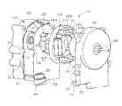
Translated fromKorean도 1은 본 발명에 따른 모터의 분해 사시도;1 is an exploded perspective view of a motor according to the present invention;
도 2는 도 1에 도시된 모터의 구성 중 일부 조립 사시도;FIG. 2 is a partially assembled perspective view of the configuration of the motor shown in FIG. 1; FIG.
도 3은 도 1에 도시된 상부 브라켓의 저면 사시도;3 is a bottom perspective view of the upper bracket shown in FIG. 1;
도 4는 도 1에 도시된 하부 브라켓과 피씨비의 결합을 도시한 평면도;4 is a plan view showing the combination of the lower bracket and the PC shown in FIG.
도 5는 도 1에 도시된 스테이터의 평면도;FIG. 5 is a plan view of the stator shown in FIG. 1; FIG.
도 6은 종래의 전원 접속용 커넥터의 고정 구조를 도시한 일부 평면도;6 is a partial plan view showing a fixing structure of a conventional power connection connector;
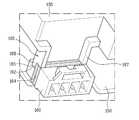
도 7은 본 발명에 따른 모터의 전원 접속용 커넥터의 고정 구조를 도시한 일부 사시도이다.7 is a partial perspective view illustrating a fixing structure of a connector for connecting a power supply of a motor according to the present invention.
<도면의 주요 부분에 대한 부호의 설명><Explanation of symbols for the main parts of the drawings>
120 : 하부 브라켓130 : 상부 브라켓120: lower bracket 130: upper bracket
140 : 스테이터141 : 스테이터 코어140: Stator 141: Stator Core
142 : 티스143 : 보빈142: Teeth 143: Bobbin
150 : 피씨비160 : 전원 접속용 커넥터150: PC 160: connector for power connection
165 : 보강부170 : 로터165: reinforcement 170: rotor
180 : 회전축190 : 홀 센서 어셈블리180: rotation axis 190: Hall sensor assembly
본 발명은 모터에 관한 것이며, 보다 상세하게는 제조가 용이하고 효율 및 내구성을 증진시킨 모터에 관한 것이다. 아울러 본 발명은 컴팩트하게 구성하여 취급 및 사용이 편리한 모터에 관한 것이다.The present invention relates to a motor, and more particularly, to a motor that is easy to manufacture and promotes efficiency and durability. In addition, the present invention relates to a motor that is compact in construction and easy to handle and use.
일반적으로 냉장고나 냉동기에 적용되는 팬 모터로서 세이딩 코일형 모터가 많이 사용된다. 이러한 세이딩 코일형 모터는 고정자에 주 코일뿐만 아니라 세이딩 코일이 권선된다.In general, a shading coil-type motor is used as a fan motor applied to a refrigerator or a freezer. Such a shading coil type motor is wound around a stator coil as well as a main coil in the stator.
이러한 세이딩 코일은 로터를 기동시키기 위한 구성으로서, 로터의 기동을 위하여 상기 주 코일과의 관계에서 타원형 자계를 형성시켜 로터가 기동되도록 한다. 그러나, 이러한 세이딩 코일은 로터가 회전을 할 때는 필요가 없는 구성으로서 이 세이딩 코일로 인한 전력 손실이 많이 발생된다.The shading coil is configured to start the rotor, and forms an elliptical magnetic field in relation to the main coil to start the rotor so that the rotor is started. However, such a shading coil is a configuration that is not necessary when the rotor rotates, and a lot of power loss is generated due to the shading coil.
아울러, 세이딩 코일을 권선하기 위한 별도의 티스부를 구비하여야 하기 때문에 스테이터의 형상이 복잡하게 되며, 별도로 세이딩 코일을 권선하여야 하므로 권선이 복잡하다.In addition, the shape of the stator is complicated because the separate teeth for winding the shading coil is provided, and the winding is complicated because the shading coil must be wound separately.
한편, 이러한 세이딩 코일 모터는 단상 교류 전원을 그대로 사용하기 때문에 전기 내지 전자적인 부품 수가 작아 원가가 낮은 장점이 있다. 그러나, 일반적으로 세이딩 코일 모터는 전력 소비량이 매우 크고, 전력 손실 또한 매우 높다.On the other hand, since the shading coil motor uses a single-phase AC power as it is, there is an advantage that the cost is low because the number of electrical or electronic components. However, in general, the shading coil motor has a very high power consumption and a high power loss.
아울러, 이러한 세이딩 코일 모터는 제어가 용이하지 않은 단점이 있으며, 일반적으로 외형 크기가 큰 단점이 있다.In addition, such a shading coil motor has a disadvantage in that it is not easy to control, and generally has a disadvantage in that its outer size is large.
따라서, 전력 소비량을 절감시키고, 외형을 컴팩트(compact)하게 형성함과 동시에 제조가 용이한 모터가 필요하게 되었다. 아울러, 단순히 팬을 구동시키는 것이 아니라 상황에 따라 용이하게 팬의 속도와 토크를 적절히 제어할 수 있는 모터가 필요하게 되었다.Accordingly, there is a need for a motor that can reduce power consumption, form an appearance compactly, and be easy to manufacture. In addition, there is a need for a motor that can easily control the speed and torque of the fan easily according to the situation, rather than simply driving the fan.
본 발명은 기본적으로 전술한 문제점을 해결하고자 함을 그 목적으로 한다.The present invention basically aims to solve the above-mentioned problems.
보다 구체적으로, 본 발명의 목적은 제조가 용이하고, 컴팩트하게 외형을 형성하여, 모터가 차지하는 공간을 줄여 그 적용 영역을 더욱 확장할 수 있도록 하고자 하는 데 있다.More specifically, an object of the present invention is to be easy to manufacture, to form a compact shape, to reduce the space occupied by the motor to further expand the application area.
또한, 본 발명의 목적은 효율을 증진시켜 전력 손실을 최소화한 모터를 제공하는 데 있다.It is also an object of the present invention to provide a motor that minimizes power loss by improving efficiency.
아울러, 본 발명의 목적은 속도 내지 토크를 용이하게 제어할 수 있는 모터를 제공하고, 보다 신뢰성 및 내구성이 증진된 모터를 제공하는 데 있다.In addition, an object of the present invention is to provide a motor that can easily control the speed to torque, and to provide a motor with improved reliability and durability.
전술한 목적을 달성하기 위하여 본 발명은, 자로를 형성하며 원주 방향을 따라 복수 개의 티스부가 구비되는 스테이터 코어; 상기 티스부에 구비되어 코일이 권선되는 티스; 그리고 상기 스테이터 코어의 원주 방향을 따라 상기 티스부와 교대로 구비되며, 반경 방향 내측으로 볼록하게 확장된 확장부를 포함하여 이루어지는 모터를 제공한다.The present invention to achieve the above object, the stator core is formed with a plurality of teeth in the circumferential direction to form a gyro; A tooth provided in the tooth part and winding a coil; And provided in the circumferential direction of the stator core alternately provided with the tooth portion, and provides a motor comprising an extended portion convexly extended in the radial direction.
여기서, 상기 확장부는 자속이 흐를 수 있는 충분한 공간을 확보하도록 하여 모터의 효율을 증진시키게 된다. 또한, 상기 확장부는 상기 티스부에 이르기까지 볼록하게 확장됨이 바람직하다. 그리고 상기 확장부를 통하여 상기 스테이터 코어의 강성을 증진시킬 수 있다.In this case, the expansion portion to secure a sufficient space for the magnetic flux flow to improve the efficiency of the motor. In addition, the extension is preferably convexly extended to the tooth portion. And it is possible to increase the rigidity of the stator core through the expansion.
그리고, 상기 스테이터 코어는 단위 스테이터 코어를 적층하여 형성될 수 있다. 즉, 회전축 방향, 다시 말하면 길이 방향으로 단위 스테이터 코어가 적층되어 형성될 수 있다. 이러한 적층 구조를 통하여 자속 방향과 수직한 방향으로 발생될 수 있는 자속의 누설을 최소화하는 것이 가능하다. 따라서, 이러한 적층 구조를 통하여 모터의 효율을 증진시킬 수 있다.The stator core may be formed by stacking unit stator cores. That is, the unit stator cores may be stacked in the rotational axis direction, that is, in the longitudinal direction. Through such a laminated structure, it is possible to minimize leakage of magnetic flux which may be generated in a direction perpendicular to the magnetic flux direction. Therefore, it is possible to improve the efficiency of the motor through such a laminated structure.
한편, 상기 적층된 단위 스테이터 코어를 일체로 결합하여야 하는데, 이러한 결합을 위하여 본원 발명에서는 코킹부가 형성된다. 한편, 이러한 코킹부를 통하여 모터의 효율이 감소되는 것을 방지하고, 아울러 코킹부를 통하여 스테이터 코어의 구조적 강도가 저하되는 것을 방지하기 위하여 상기 코킹부는 상기 확장부에 형성됨이 바람직하다. 즉, 충분한 두께를 갖는 상기 확장부에 상기 단위 스테이터 코어들을 일체로 결합시키는 코킹부가 형성됨이 바람직하다. 따라서, 상기 코킹부는 상기 확장부 중 가장 두께가 두꺼운 중앙 부분에 형성됨이 바람직하다.Meanwhile, the stacked unit stator cores must be integrally coupled to each other. In the present invention, a caulking portion is formed. On the other hand, in order to prevent the efficiency of the motor from being reduced through such a caulking portion, and to prevent the structural strength of the stator core from falling through the caulking portion, it is preferable that the caulking portion is formed in the expansion portion. That is, it is preferable that a caulking portion for integrally coupling the unit stator cores to the expansion portion having a sufficient thickness is formed. Therefore, the caulking portion is preferably formed in the central portion thickest of the extension portion.
한편, 상기 티스는 상기 스테이터 코어와 일체로 형성될 수 있다. 즉, 단위 스테이터가 타발되어 형성될 때, 상기 티스도 함께 형성될 수 있다. 그러나, 상기 티스는 상기 스테이터 코어와 별도로 형성된 후, 상기 티스부에 결합될 수 있다. 즉, 상기 티스의 일단부가 상기 티스부에 형성된 티스 슬롯에 압입되어 양자가 결합될 수도 있다.On the other hand, the teeth may be formed integrally with the stator core. That is, when the unit stator is formed by punching out, the teeth may be formed together. However, the teeth may be formed separately from the stator core and then joined to the teeth portion. That is, one end of the tooth may be press-fitted into the tooth slot formed in the tooth part, and both may be combined.
또한, 본 발명은 티스부의 외측에 형성되는 홈을 포함하여 이루어질 수 있다. 상기 홈은 스테이터 코어의 길이 방향으로 형성되며, 타발 금형에서 상기 스테이터 코어, 즉, 단위 스테이터 코어를 타발 금형에서 용이하게 분리시키기 위한 것이다.In addition, the present invention may include a groove formed on the outside of the tooth portion. The groove is formed in the longitudinal direction of the stator core and is for easily separating the stator core, that is, the unit stator core, from the punching mold in the punching mold.
아울러, 상기 홈은 상기 티스 슬롯에 대응되는 부위에 형성됨이 바람직하고, 특히 상기 티스 슬롯의 중앙부에 대응되도록 형성됨이 바람직하다. 다시 말하면, 상기 티스 슬롯이 스테이터 코어의 내측 특정 부분에 형성되는 경우, 상기 홈은 상기 슬롯이 형성된 스테이터 코어의 외측에 형성됨이 바람직하다. 이러한 홈을 통해서, 상기 티스가 상기 티스 슬롯에 압입될 때 발생되는 상기 스테이터 코어의 치수 변화를 최소화할 수 있다.In addition, the groove is preferably formed in a portion corresponding to the tooth slot, it is particularly preferably formed to correspond to the central portion of the tooth slot. In other words, when the tooth slot is formed in the inner specific portion of the stator core, the groove is preferably formed outside the stator core in which the slot is formed. Through this groove, it is possible to minimize the dimensional change of the stator core generated when the tooth is pressed into the tooth slot.
한편, 상기 스테이터는 중앙부에 상기 티스가 삽입되어 직접 상기 코일이 권선되는 보빈을 더 포함하여 이루어질 수 있다. 이러한 보빈은 상기 티스와 상기 코일 간의 절연 기능을 수행하게 함과 동시에, 안정적으로 코일이 고정되는 기능을 수행한다.Meanwhile, the stator may further include a bobbin in which the teeth are inserted in the central portion and the coil is directly wound. The bobbin performs an insulation function between the tooth and the coil and at the same time performs a function of stably fixing the coil.
보다 구체적으로, 상기 보빈은 상기 코일이 고정되어 이탈되지 않도록 내측벽과 외측벽을 포함하여 이루어지며, 상기 외측벽은 상기 티스부와 접함이 바람직하다. 아울러, 상기 티스부의 내벽은 평면 형상으로 형성됨이 바람직하다. 이를 통하여 상기 보빈이 보다 안정적으로 고정되는 것이 가능할 것이다.More specifically, the bobbin includes an inner wall and an outer wall so that the coil is fixed and separated, and the outer wall is preferably in contact with the tooth portion. In addition, the inner wall of the tooth portion is preferably formed in a planar shape. Through this, it will be possible to fix the bobbin more stably.
전술한 목적을 달성하기 위하여 본원 발명에 따른 모터는 비엘디씨 모터일 수 있다.In order to achieve the above object, the motor according to the present invention may be a BCD motor.
보다 구체적으로 본 발명은, 자로를 형성하며 원주 방향을 따라 복수 개의 티스부가 구비되는 스테이터 코어, 상기 티스부에 구비되어 코일이 권선되는 티스, 그리고 상기 스테이터 코어의 원주 방향을 따라 상기 티스부와 교대로 구비되며, 반경 방향 내측으로 볼록하게 확장된 확장부를 갖는 스테이터; 그리고 상기 스테이터의 내측에 위치되어 회전하며, 외주면을 따라 교대로 자극이 형성되도록 영구자석이 구비된 로터를 포함하여 이루어지며, 상기 확장부는 이웃하는 두 개의 티스부 사이의 전 영역에 형성됨을 특징으로 하는 비엘디씨 모터를 제공한다.More specifically, the present invention forms a stator core having a plurality of teeth portions along the circumferential direction, teeth provided on the teeth portion, the coil being wound, and alternating with the teeth portion along the circumferential direction of the stator core. It is provided with a stator having a radially inwardly extending convex extension; And a rotor disposed inside the stator, the rotor having a permanent magnet so that magnetic poles are alternately formed along an outer circumferential surface, and the extension part is formed in an entire region between two neighboring tooth parts. Provides BCD motor.
여기서, 상기 티스의 선단부에는 마주보는 상기 로터의 외주면과 부합되도록 양측 원주 방향으로 일정 길이 연장되도록 폴슈가 형성됨이 바람직하다.Here, the front end of the tooth is preferably formed of a fold shoe so as to extend a predetermined length in both circumferential directions to match the outer peripheral surface of the rotor facing.
아울러, 상기 폴슈의 양측 또는 일측에는 코깅 토크의 최소화를 위한 절개부가 형성됨이 바람직하다. 여기서, 상기 절개부는 폴슈의 말단부에 형성되며, 다른 부분의 두께보다는 얇도록 길이 방향으로 형성될 수 있다.In addition, it is preferable that cutouts for minimizing cogging torque are formed on both sides or one side of the polshes. Here, the cutout is formed at the distal end of the polche, it may be formed in the longitudinal direction to be thinner than the thickness of the other portion.
한편, 전술한 목적을 달성하기 위하여 본 발명은 외형을 형성하는 브라켓과 상기 브라켓 내부에 수용되며, 전기적 패턴과 각종 소자들이 실장되는 피씨비가 더 포함되어 이루어진다.On the other hand, in order to achieve the above object, the present invention is made of a bracket that forms the outer shape and the inside of the bracket, the PCB and the electrical pattern and the various elements are further included.
여기서, 상기 피씨비 상에는 스테이터가 구비되며, 상기 스테이터의 내부 또는 외부에는 상기 스테이터에 대해서 회전하는 로터가 구비된다. 아울러, 상기 로터와 일체로 회전하여 상기 로터의 회전력을 외부의 부하를 구동하기 위한 회전축이 더 포함되어 이루어진다.Here, a stator is provided on the PCB, and a rotor that rotates with respect to the stator is provided inside or outside the stator. In addition, the rotation shaft is integrally formed with the rotor for driving the external load of the rotational force of the rotor is further included.
본 발명은, 특히, 상기 브라켓의 내부로 돌출되어 상기 로터의 상기 회전축 방향으로의 이동을 제한하는 스토퍼를 더 포함하여 이루어진다.The present invention further comprises a stopper, particularly protruding into the bracket to limit the movement of the rotor in the direction of the rotation axis.
즉, 상기 회전축은 상기 로터의 내부에 압입되어 상기 로터와 결합될 수 있는데, 상기 로터가 진동 등에 의하여 심한 경우 상기 회전축을 따라 이동하는 경우가 발생될 수 있다. 이러한 로터의 이동에 의해서 전술한 피씨비가 손상될 우려가 있다.That is, the rotating shaft may be pressed into the rotor and combined with the rotor. When the rotor is severely vibrated, the rotor may move along the rotating shaft. Such movement of the rotor may damage the above-mentioned PCB.
따라서, 이러한 로터의 이동을 제한하기 위한 스토퍼가 브라켓과 일체로 형성되어 내부로 돌출되어 형성될 수 있다.Therefore, the stopper for limiting the movement of the rotor may be formed integrally with the bracket to protrude into the inside.
또한, 상기 피씨비에는 중공이 형성될 수 있다. 그리고, 상기 중공에 상기 스토퍼가 삽입될 수 있다. 즉, 피씨비가 브라켓 내부에 안착될 때, 상기 피씨비의 중공에 상기 스토퍼가 삽입되어, 피씨비의 위치가 맞춰지는 기능 또한 수행할 수 있다.In addition, the PC may be hollow. In addition, the stopper may be inserted into the hollow. That is, when the PCB is seated inside the bracket, the stopper is inserted into the hollow of the PCB, so that the position of the PCB may be adjusted.
상기 브라켓은 서로 결합되는 상부 브라켓과 하부 브라켓을 포함하여 이루어질 수 있다. 그리고, 상기 스토퍼는 상기 상부 브라켓과 하부 브라켓 각각에 형성될 수 있다. 다시 말하면, 하부 브라켓에 형성된 스토퍼는 상기 로터가 회전축에 대해서 아래로 이동되는 것을 방지하고, 상부 브라켓에 형성된 스토퍼는 상기 로터가 회전축에 대해서 상부로 이동되는 것을 방지하게 된다. 따라서, 상기 로터는 결국 양측의 스토퍼 내부에 위치되게 된다.The bracket may include an upper bracket and a lower bracket coupled to each other. The stopper may be formed in each of the upper bracket and the lower bracket. In other words, the stopper formed on the lower bracket prevents the rotor from moving downward with respect to the rotating shaft, and the stopper formed on the upper bracket prevents the rotor from moving upward with respect to the rotating shaft. Thus, the rotor is eventually placed inside the stoppers on both sides.
또한, 상기 스토퍼는 원통형으로 돌출되어 형성될 수 있다. 그리고, 상기 스토퍼의 상면이 상기 로터의 상면 또는 하면과 맞닿을 수 있도록, 상기 스토퍼의 외경 또는 내경이 결정되어 형성됨이 바람직하다.In addition, the stopper may be formed to protrude in a cylindrical shape. The outer or inner diameter of the stopper may be determined and formed so that the upper surface of the stopper may contact the upper or lower surface of the rotor.
한편, 본 발명에 있어서, 피씨비의 적어도 일부분의 형상은 상기 스테이터의외형 형상과 부합되도록 형성됨이 바람직하다. 상기 스테이터는 환형으로 형성될 수 있다. 따라서, 상기 스테이터의 형상에 부합되도록 상기 피씨비의 적어도 일부분의 형상은 원형으로 형성됨이 바람직하다. 즉, 스테이터가 구비되는 부분의 피씨비 형상은 원형이며, 이외의 부분은 사각형 형태로 형성될 수도 있다.On the other hand, in the present invention, it is preferable that the shape of at least a portion of the PC ratio is formed to match the external shape of the stator. The stator may be formed in an annular shape. Therefore, the shape of at least a portion of the PC ratio is preferably formed in a circle so as to match the shape of the stator. That is, the PC ratio shape of the portion where the stator is provided may be circular, and other portions may be formed in a square shape.
마찬가지로, 상기 브라켓의 형상은 상기 피씨비의 형상에 부합되도록 형성됨이 바람직하다. 이를 통하여 전체적인 모터의 외형을 컴팩트하게 형성함과 동시에 미려한 외관을 형성하는 것이 가능하다.Similarly, the shape of the bracket is preferably formed to match the shape of the PC. This makes it possible to form the overall appearance of the motor compactly and at the same time beautiful appearance.
한편, 전술한 목적을 달성하기 위하여 본 발명은 또한, 자로를 형성하는 스테이터 코어, 상기 스테이터 코어에 구비된 복수 개의 티스, 그리고 상기 티스에 구비되어 코일이 권선되는 보빈을 갖는 스테이터; 그리고 상기 보빈에 형성된 핀을 통하여 상기 코일과 전기적으로 연결됨과 동시에 상기 스테이터가 고정되는 피씨비를 포함하여 이루어지며, 상기 피씨비의 적어도 일부분은 상기 스테이터의 형상과 부합되도록 형성되며, 상기 핀이 삽입되도록 홀이 형성된 부분에는 외측으로 확장된 확장부가 형성된 모터를 제공한다.On the other hand, in order to achieve the above object, the present invention also provides a stator core for forming a magnetic path, a plurality of teeth provided on the stator core, and a stator having a bobbin is provided on the teeth wound coil; And a PCB which is electrically connected to the coil through a pin formed in the bobbin and at which the stator is fixed. At least a portion of the PCB is formed to match the shape of the stator. The formed portion is provided with a motor having an extended portion extended outward.
여기서, 상기 피씨비 중 상기 스테이터의 형상과 부합되도록 형성된 부분은 실질적으로 상기 스테이터의 외경과 동일하도록 형성됨이 바람직하다. 왜냐하면 피씨비의 크기로 인한 전체적인 모터의 외형이 커지는 것을 방지하기 위함이다.Here, the portion of the PC ratio formed to match the shape of the stator is preferably formed to be substantially the same as the outer diameter of the stator. This is to prevent the overall appearance of the motor from increasing due to the size of the PC.
따라서, 상기 피씨비는 적어도 일부분이 원형으로 형성될 수 있다.Thus, the PC may be formed at least partially in a circular shape.
그리고, 상기 스테이터는 상기 보빈에 형성된 핀이 상기 피씨비에 형성된 홀 에 삽입됨으로써 코일과 피씨비 간의 전기적 연결이 이루어진다. 아울러, 상기 스테이터가 상기 피씨비 상에서 고정되는 기능도 수행할 수 있다.The stator has an electrical connection between the coil and the PC by inserting a pin formed in the bobbin into a hole formed in the PC. In addition, the stator may perform a function of being fixed on the PC.
이 경우, 상기 보빈의 위치와 이에 따른 상기 핀의 위치에 따라서, 상기 핀이 삽입되는 홀은 상기 피씨비의 최외곽 부분에 위치될 수 있다. 따라서, 이 부분의 강도가 저하될 우려가 있다. 따라서, 본 발명에서는 상기 홀이 형성된 부분에서 외측으로 확장된 확장부가 형성됨이 바람직하다. 즉, 반경 방향 외측으로 볼록하게 확장되는 것이 바람직하다.In this case, according to the position of the bobbin and thus the position of the pin, the hole into which the pin is inserted may be located at the outermost part of the PC. Therefore, there exists a possibility that the intensity | strength of this part may fall. Therefore, in the present invention, it is preferable that an expansion portion extended outward is formed at the portion where the hole is formed. That is, it is preferable to extend convexly outward in the radial direction.
물론, 피씨비를 전체적으로 더 크게 형성함으로써 상기 홀이 형성된 부분의 강도를 보강할 수 있다. 그러나, 이 경우 피씨비가 커지기 때문에 전체적인 모터의 외형이 커지는 문제점이 있다.Of course, it is possible to reinforce the strength of the portion where the hole is formed by forming a larger PC overall. However, in this case, there is a problem that the overall appearance of the motor is large because the PC ratio is large.
한편, 상기 피씨비는 상기 하부 브라켓에 안착되어 고정될 수 있는 데, 상기 하부 브라켓의 내측에는 상기 확장부가 안착되도록 상기 확장부의 형상과 부합되도록 홈이 형성됨이 바람직하다. 물론, 상기 하부 브라켓과 상부 브라켓은 상기 피씨비의 형상과 부합되도록 형성됨이 더욱 바람직할 것이다.On the other hand, the PC may be fixed to the lower bracket is fixed, it is preferable that the groove is formed on the inner side of the lower bracket to match the shape of the expansion portion to be seated. Of course, the lower bracket and the upper bracket will be more preferably formed to match the shape of the PC.
이하에서는 첨부된 도면을 참조하여 본 발명에 따른 모터를 상세하게 설명한다.Hereinafter, with reference to the accompanying drawings will be described in detail a motor according to the present invention.
도 1은 본 발명에 따른 모터(100)의 분해 사시도이다.1 is an exploded perspective view of a
도 1에 도시된 바와 같이, 본 발명에 따른 모터는 외형을 형성하는 브라켓(110), 상기 브라켓 내부에 수용되며, 전기적 패턴(미도시)이 형성되고 각종 소자(미도시)들이 실장되는 피씨비(PCB)(150), 스테이터(140), 로터(170), 그리고 회 전축(180)을 포함하여 이루어진다.As shown in FIG. 1, the motor according to the present invention includes a
여기서, 상기 브라켓(110)은 하부 브라켓(120)과 상부 브라켓(130)을 포함하여 이루어져, 양자가 결합되어 내부의 각종 구성들을 수용하게 된다. 이러한 브라켓의 결합은 체결보스(122, 132)와 상기 체결보스에 형성된 체결홀(121, 131)을 서로 맞추고, 나사(미도시)를 이용하여 이루어질 수 있다.Here, the
먼저, 도 1과 도 5를 참조하여 본 발명에 따른 모터의 스테이터(140)에 대해서 상세히 설명한다.First, the
상기 스테이터(140)는 스테이터 코어(141)와 티스(142)를 포함하여 이루어진다.The
상기 스테이터 코어(141)는 도시된 바와 같이 환형으로 형성될 수 있으며, 자로를 형성하게 된다. 그리고, 상기 티스(142)는 상기 스테이터 코어(141)의 반경 방향으로 돌출되며, 상기 티스에 코일이 권선된다. 도시된 모터는 일례로 스테이터 코어(141)의 내부에 로터(170)이 위치되는 이너(inner) 로터 타입 모터이므로, 상기 티스(142)는 상기 스테이터 코어(141)의 반경 방향 내측으로 돌출되어 형성된다. 한편, 이러한 티스(142)는 복수 개 형성되며, 도 5에는 일례로 티스가 4개 형성된 것이 도시되어 있다.The
한편, 상기 스테이터 코어(141)의 내측 원주 방향을 따라 복수 개의 티스부(144)와 확장부(145)가 번갈아 가면서 형성된다. 여기서, 상기 티스(142)는 상기 티스부(144)에 구비된다. 그리고 상기 확장부(145)는 반경 방향 내측으로 볼록하게 확장되도록 형성된다.Meanwhile, the plurality of
여기서, 상기 확장부(145)는 이웃하는 티스부(144) 사이에서 전체적으로 반경 방향 내측으로 볼록하게 확장됨이 바람직하다. 즉, 상기 확장부(145)는 전체적으로 그 두께를 키우는 것이 바람직하다. 이는 자속이 형성되는 공간을 충분히 확보하여 자속 포화로 인한 누설 자속을 최소화하여 모터의 효율을 최대화하기 위함이다. 아울러, 스테이터 코어의 두께를 키워 스테이터 코어(141)의 구조적 강도를 보강하기 위함이다.Here, the
물론, 이러한 확장부(145)는 반경 방향 외측으로 형성될 수도 있다. 그러나, 이 경우 스테이터 코어(141)의 크기가 커져 전체적인 모터의 외형이 커질 수 있다.Of course, this
상기 스테이터 코어(141)는 단위 스테이터 코어를 적층하여 형성될 수 있다. 즉, 얇은 단위 스테이터 코어를 복수 개 적층하여 소정 높이를 갖는 스테이터 코어(141)를 형성할 수 있다. 이러한 방법으로 스테이터 코어(141)를 형성하는 경우에는 자속의 수직한 방향으로 형성될 수 있는 누설 자속을 최소화하여 모터의 효율을 증진시킬 수 있다. 아울러, 상기 티스(142) 또한 이러한 적층 방법으로 형성됨이 바람직하다.The
이러한 적층 형태로 스테이터 코어(141)를 형성하는 경우 상기 단위 스테이터 코어들을 일체로 결합시킬 필요가 있다. 즉, 일체로 형성된 하나의 스테이터 코어(141)를 형성할 필요가 있다. 따라서, 이러한 단위 스테이터 코어들을 결합시키기 위한 코킹(caulking)부가 필요하다. 이러한 코킹부는 스테이터 코어의 상하부를 관통하여 형성되기 때문에 폭이 넓은 부분에 형성됨이 바람직하다. 그리고, 이러한 코킹부로 인한 자속의 왜곡이나 누설을 최소화하기 위하여 폭이 넓은 부분에 형성 됨이 바람직하다.When the
따라서, 본 발명에서는 상기 코킹부(146)가 상기 확장부(145)에 형성됨이 바람직하다. 아울러, 상기 확장부(145) 중에서도 가능 폭이 큰 부분인, 확장부(145)의 중앙 부분에 형성됨이 바람직하다.Therefore, in the present invention, the
이를 통해서, 보다 안정적으로 코킹(caulking)을 이룰 수 있으며, 이러한 코킹부(146)를 통해서 스테이터 코어(141)의 변형을 최소화할 수 있고, 코킹부로 인한 효율 저감을 방지할 수 있다.Through this, caulking can be more stably achieved, and through this
한편, 본 발명에서 상기 티스(142)는 상기 스테이터 코어(141)와 일체로 형성될 수 있다. 즉, 처음부터 하나의 몸체로 형성될 수 있다. 그러나, 권선의 용이 및 스테이터 제작의 용이를 위하여 상기 티스(142)는 상기 스테이터 코어(141)와 별도로 형성된 후 상기 스테이터 코어(141)에 결합될 수 있다.Meanwhile, in the present invention, the
즉, 상기 스테이터 코어(141)의 티스부(144)의 중앙 부분에 티스 슬롯(147)이 형성되고, 상기 티스 슬롯(147)에 상기 티스(142)의 일단부가 압입되어 양자의 결합이 이루어질 수 있다.That is, a
따라서, 후술하는 보빈(143)에 티스(142)를 삽입시키고, 상기 보빈에 코일을 권선한 후 상기 티스(142)를 상기 티스 슬롯(147)에 압입시킬 수 있다. 그러므로 보빈(143)과 티스(142)의 결합이 매우 용이하고, 권선이 매우 용이한 장점이 있다.Accordingly, the
한편, 상기 스테이터 코어(141)의 외주면에는 회전축의 길이 방향, 즉 스테이터 코어(141)의 높이 방향으로 홈(148)이 형성됨이 바람직하다. 이러한 홈(148)은 상기 스테이터 코어(141)의 외주면 원주 방향을 따라 복수 개 형성됨이 바람직 하다.On the other hand, the outer peripheral surface of the
상기 홈(148)은 상기 단위 스테이터 코어들을 타발하여 형성할 때, 타발 금형에서 상기 단위 스테이터 코어들이 용이하게 분리될 수 있도록 하는 기능을 수행하게 된다. 즉, 상기 홈(148)을 통해서 금형의 내부 압력과 외부 압력이 동일하게 되어 분리가 용이하며, 아울러 분리 시의 가이드 기능을 수행하게 되므로 분리가 더욱 용이하다.When the
본 발명에서는 상기 홈(148)이 상기 스테이터 코어(141)의 티스부(147)의 외측에 형성됨이 바람직하다. 즉, 상기 티스(142)가 상기 티스 슬롯(147)에 압입될 때 발생되는 상기 스테이터 코어(141)의 치수 변화를 최소화하기 위함이다. 따라서, 이러한 기능을 수행하기 위해서 상기 홈(148)은 상기 티스 슬롯(147)의 중앙부에 대응되어 형성됨이 더욱 바람직하다.In the present invention, the
본 발명에서는 코일이 직접 티스(142)에 권선되지 않고, 코일과 티스 사이의 절연 및 권선의 용이를 위하여 구성된 보빈(143)에 코일이 권선됨이 바람직하다.In the present invention, it is preferable that the coil is not wound directly on the
상기 보빈(143)은 내측벽(143a), 권선부(143b), 그리고 외측벽(143c)로 이루어질 수 있다. 즉, 내측벽(143a)과 외측벽(143c) 사이의 권선부(143b)에 코일이 권선되며, 상기 내측벽과 외측벽은 코일이 이탈되는 것을 방지하는 기능을 수행한다.The
여기서, 상기 보빈(143)의 외측벽(143c)은 상기 스테이터 코어(141)의 티스부(144)와 접하도록 구성됨이 바람직하다. 즉, 상기 티스부(144)는 상기 보빈의 외측벽(143c)와 접하도록 내벽이 평면 형상으로 형성됨이 바람직하다. 이를 통해서 상기 보빈(143)이 보다 안정적으로 상기 스테이터 코어(141)에 결합되는 것이 가능 하다.Here, the
한편, 본 발명에 따른 모터는 예를 들어 4 개의 티스(142)를 가질 수 있다. 이 경우, 상기 티스에 권선되는 코일에 전원이 인가되면, 상기 각각의 티스에는 N극과 S극의 자극의 교대로 형성된다. 즉, 도 5에 도시된 티스 중 가장 상부에 위치된 티스에 N극이 형성된 경우에는 이웃한 티스들에는 S극이 형성된다.On the other hand, the motor according to the present invention may have four
즉, 이러한 티스를 중심으로 자극이 형성되는 데, 상기 티스와 티스 사이의 거리가 떨어질수록 누설되는 자속이 증가된다. 따라서, 누설 자속을 최소화하기 위하여 상기 티스의 선단부에는 마주보는 로터의 외주면과 부합되도록 양측 원주 방향으로 일정 길이 연장되도록 폴슈(pole shoe)(149)가 형성됨이 바람직하다. 이를 통해서 이웃하는 티스 사이에 발생되는 누설 자속을 최소화할 수 있다.That is, the magnetic pole is formed around the tooth, and the magnetic flux leaking increases as the distance between the tooth and the tooth decreases. Accordingly, in order to minimize the leakage magnetic flux, a
한편, 도 5에 도시된 바와 같이 특정 티스에 형성된 폴슈(149)는 이웃하는 티스에 형성된 폴슈(149)와 연결되지 않음이 바람직하다. 왜냐하면 양 폴슈에는 서로 다른 자극이 형성되는데, 이들이 연결되면 자극의 상쇄가 발생되어 오히려 효율이 저하될 수 있기 때문이다.On the other hand, as shown in Figure 5 is preferably a
이러한 누설 자속을 최소화하기 위한 폴슈(149)의 형상과 함께, 티스와 티스 사이의 자극의 급격한 변화로 인한 로터(170)와 회전축(180)에서 발생되는 코깅 토크(cogging torque)나 토크 리플(torque ripple)을 줄이는 것이 바람직하다. 이러한 코깅 토크는 모터의 제어를 어렵게 하고, 진동이나 소음을 유발시킬 수 있기 때문이다.Along with the shape of the
따라서, 티스와 티스 사이에서 자극의 급격한 변화를 완화시키는 것이 바람 직하다.Thus, it is desirable to mitigate the abrupt change in stimulation between the teeth and the teeth.
본 발명에서는 이러한 코깅 토크를 최소화하기 위하여 폴슈(149)의 양측 또는 일측에 절개부가 형성될 수 있다. 즉, 이러한 절개부(149a)를 통해서 자속 밀도를 감소시켜, 급격한 자극의 변화를 방지할 수 있다. 물론, 이러한 절개부를 통해서 누설 자속이 커질 수 있다. 따라서, 일측의 폴슈에만 이러한 절개부(149a)가 형성됨이 바람직하다.In the present invention, incisions may be formed on both sides or one side of the
특히, 상기 절개부(149a)는 상기 폴슈의 말단부에 형성되며, 다른 부분의 두께보다는 얇도록 길이 방향으로 형성되는 것이 바람직하다.In particular, the
이하에서는, 도 1과 도 4를 참조하여 본 발명에 따른 모터의 피씨비(PCB)(150)에 대하여 상세히 설명한다. 여기서, 도 4는 하부 브라켓(120)에 피씨비가 안착된 상태를 도시한 평명도이다.Hereinafter, the
도 1과 도 5에 도시된 바와 같이, 본 발명에 따른 모터의 스테이터(140)는 환형으로 형성될 수 있다. 그리고 이러한 스테이터(140)의 형상에 부합하여 상기 피씨비(150)는 적어도 일부분이 원형으로 형성될 수 있다. 즉, 도 1과 도 4에 도시된 바와 같이, 스테이터(140)가 안착되는 피씨비(150)의 상측 부분은 원형으로 형성될 수 있다.As shown in Figure 1 and 5, the
이러한 피씨비(150)의 원형 부분의 반경은 상기 스테이터 코어(141)의 반경과 실질적으로 동일함이 바람직하다. 왜냐하면 피씨비의 외형이 커짐으로 인하여 피씨비가 수용되는 브라켓(110)의 크기가 커져 전체적인 모터의 크기가 커질 수 있기 때문이다. 따라서, 피씨비(150)의 형상 중 일부를 원형으로 형성함으로써 컴팩 트한 모터를 제공할 수 있다.The radius of this circular portion of the
아울러, 이러한 피씨비(150)의 형상, 그리고 상기 피씨비의 형상에 부합하도록 브라켓(110)을 형성함으로써 외관이 미려한 모터를 제공할 수 있다.In addition, by forming the
한편, 상기 보빈(143)의 하부 양측에는 핀(143d)이 형성된다. 상기 핀(143d)은 상기 보빈에 권선되는 코일과 전기적으로 연결되어 있다. 따라서, 상기 핀(143d)이 피씨비(150)에 형성된 홀(151)에 삽입되어 상기 피씨비와 상기 코일 사이에 전기적인 연결이 이루어진다. 상기 핀(143d)이 상기 피씨비(150)의 홀(151)에 삽입된 후, 안정적인 전기적 연결을 위해 솔더링이 이루어질 수 있다.Meanwhile, pins 143d are formed at both lower sides of the
여기서, 상기 핀(143d)은 단순히 상기 피씨비와의 사이에 전기적인 연결뿐만 아니라, 상기 보빈(143)을 통하여 상기 피씨비(150)의 상부에 상기 스테이터(140)이 안착되어 고정되는 기능을 수행한다. 따라서, 상기 핀(143d)은 상기 피씨비(150)와의 접촉 면적을 높임과 동시에 스테이터의 무게를 지탱할 수 있도록 보스(143e)에 형성된다.Here, the
이러한 보스(143e)는 외측벽(143c)의 하부에 형성되며, 상기 피씨비(150)와 스테이터 코어(141) 사이의 간격을 유지하는 기능을 수행한다.The
한편, 상기 피씨비(150)의 일측에는 전원 접속용 커넥터(160)가 구비된다. 상기 전원 접속용 커넥터(160)의 일단에는 핀(161)이 형성되어, 상기 핀(161)을 통하여 상기 전원 접속용 커넥터(160)가 상기 피씨비(150)에 고정됨과 함께 전기적으로 연결된다. 이러한 핀(161)은 피씨비(150)에 형성된 홀(152)에 삽입된다. 아울러, 상기 접원 접속용 탭(160)의 타단은 모터의 외부, 즉 브라켓(110)의 외부로 노 출되어 외부의 전원과 연결된다.On the other hand, one side of the
또한, 상기 피씨비(150) 중 로터(170)의 위치와 부합되는 부분에는 홀 센서 어셈블리(190)가 구비된다. 상기 홀 센서 어셈블리는 로터(170)의 회전 위치나 회전 속도를 센싱하는 기능을 수행한다. 이러한 홀 센서 어셈블리의 센싱을 통하여 로터의 회전 속도나 토크 등이 제어된다. 따라서, 상기 피씨비(150)에는 상기 홀 센서 어셈블리(190)의 고정과 전기적 연결을 위한 홀(153)이 형성된다.In addition, the
또한, 전술한 바와 같이 본 발명에 따른 모터의 티스(142)는 4개일 수 있으므로, 이에 따라 상기 보빈이 결합되는 개소는 4개가 된다.In addition, as described above, since the
한편, 도 1과 도 4에 도시된 바와 같이, 피씨비의 외형은 일부분이 원형으로 형성된다. 따라서, 상기 보빈이 결합되는 개소 중 일정 개소는 원형 부분의 피씨비에 형성된다. 그리고 전술한 바와 같이 이러한 원형 부분은 상기 스테이터(140)의 외형과 부합되도록 하기 위함이다.On the other hand, as shown in Figures 1 and 4, the appearance of the PCB is formed in a circular portion. Therefore, a certain part of the places where the said bobbin is couple | bonded is formed in the PC ratio of a circular part. And as described above, this circular portion is to match the outer shape of the
그러나, 피씨비의 외형을 줄여 컴팩트한 모터를 제공하기 위하여, 상기 홀(151)들 중 일정 홀(151)은 상기 원형 부분의 피씨비(150)의 최외곽에 형성됨이 바람직하다. 즉, 피씨비(150)의 테두리 부분에 형성됨이 바람직하다. 따라서, 이러한 홀(151)이 형성된 부분은 강도가 약할 것이며, 홀 형성시 불량이 발생될 우려가 있다. 또한, 진동 등에 의해서 상기 홀(151) 부분이 손상될 우려도 있다.However, in order to provide a compact motor by reducing the appearance of the PCB, a
이러한 문제를 해결하기 위하여, 상기 피씨비의 일정 부분, 즉 상기 홀(151)이 형성되는 부분에는 외측으로 확장된 확장부(154)가 형성됨이 바람직하다. 즉, 상기 확장부(154)를 통하여 피씨비(150)의 최외곽과 상기 홀(151) 사이에는 일정 거리가 확보될 수 있다. 따라서, 상기 홀(151) 부분의 강성이 보강될 수 있다. 그리고 일부분에만 이러한 확장부(154)가 형성되므로 전체적으로 피씨비(150)의 외형이 커지는 것을 방지할 수 있다. 아울러, 이러한 확장부(154)를 통하여 피씨비(150)가 용이하게 브라켓(110)에 안착되어 고정될 수 있게 된다.In order to solve this problem, it is preferable that an
또한, 상기 피씨비(150)에는 중공(155)이 형성된다. 즉, 스테이터가 안착되는 부분의 중심부에 상기 중공이 형성될 수 있다. 이러한 중공(155)에는 후술하는 스토퍼가 삽입되며, 이러한 스토퍼를 통하여 로터(170)와 피씨비(150)의 간섭이 방지된다.In addition, the
아울러, 상기 스토퍼가 상기 중공(155)에 삽입되므로 보다 안정적으로 피씨비가 브라켓(110)에 안착되어 고정될 수 있다.In addition, since the stopper is inserted into the hollow 155, the PCB may be more securely seated on the
이하에서는 도 2와 도 3을 참조하여 본 발명에 따른 모터의 브라켓(110)에 대해서 상세히 설명한다.Hereinafter, the
먼저, 본 발명에 따른 브라켓(110)은 양자가 결합되어 내부에 여러 구성들을 수용하도록 하부 브라켓(120)과 상부 브라켓(130)으로 이루어질 수 있음을 전술하였다. 그리고 상기 하부 브라켓(120)에는 본 발명에 따른 모터가 적용되는 각종 제품들에 상기 모터(100)가 장착되기 위한 장착부(123)가 형성될 수 있다.First, the
한편, 본 발명에 따른 브라켓(110)은 전술한 바와 같이 피씨비(150)의 형상과 부합되도록 형성된다. 그리고, 상기 피씨비(150)는 브라켓(110), 특히 하부 브라켓(120)의 내측에 안착된다.On the other hand, the
여기서, 상기 하부 브라켓(120)에는 상기 피씨비(150)의 확장부(154)가 안착 되도록 상기 확장부의 형상에 부합되도록 홈(124)이 형성됨이 바람직하다. 이러한 홈(124)에 상기 확장부(154)가 안착되므로 피씨비가 상기 하부 브라켓(120)에 안착될 때 위치가 자동적으로 조정될 수 있다. 물론, 보다 안정적으로 안착될 수 있게 된다.Here, the
한편, 상기 하부 브라켓(120)에는 상기 스테이터가 안착되기 위하여 후술하는 단차부(128)이 형성된다. 이러한 단차부는 상기 하부 브라켓이 내벽에서 일정 거리 브라켓 내부로 돌출되도록 형성된다. 따라서, 상기 홈(124)로 인한 브라켓의 형상이 커짐을 방지하기 위하여, 상기 홈(124)은 상기 단차부(128)의 일부를 절개한 형태로 형성됨이 바람직하다.On the other hand, the
도 2에 도시된 바와 같이, 상기 피씨비(150)는 먼저 하부 브라켓(120)의 내부에 안착된다. 이때, 전술한 바와 같이 상기 피씨비(150)에 형성된 중공(155)에는 스토퍼(155)가 삽입된다.As shown in FIG. 2, the
그리고, 상기 피씨비(150)의 상부에 스테이터(140)가 위치하고, 상기 스테이터(140)의 내부에 로터(170) 및 회전축(180)이 위치된다.In addition, the
상기, 회전축의 일단은 상기 하부 브라켓(120)에 구비되는 베어링(126)에 의해서 회전 가능하게 지지되며, 아울러 추력도 지지된다. 그리고, 상기 회전축(180)의 타단은 상부 브라켓(120)에 구비되는 베어링(136)에 의해서 회전 가능하게 지지된다. 여기서, 상기 회전축은 관통공(137)을 통해서 외부로 노출되어 부하를 구동시키게 된다.The one end of the rotating shaft is rotatably supported by the bearing 126 provided on the
한편, 상기 로터(170)의 내부에는 상기 회전축(180)이 압입되어 일체로 회전 하게 된다. 이러한 결합 방식에 의해 상기 회전축(180)의 길이 방향으로 상기 로터(170)가 이동되는 것이 방지된다. 이러한 상태가 도 2에 도시되어 있다.On the other hand, the
그러나, 상기 로터는 진동에 의해서 상기 회전축의 길이 방향으로 이동되는 문제가 발생될 수 있다. 이러한 로터의 이동에 의해서 상기 로터와 상기 피씨비(150) 간의 간섭이 발생하여, 피씨비(150)가 손상될 수 있다.However, the rotor may be moved by the vibration in the longitudinal direction of the rotation axis may occur. Due to the movement of the rotor, the interference between the rotor and the
이러한 문제를 방지하기 위하여 전술한 바와 같이 상기 회전축(180) 방향으로 로터가 이동하는 것을 제한하는 스토퍼(125)가 형성됨이 바람직하다. 상기 스토퍼는 상기 브라켓의 내부로 돌출되도록 형성됨이 바람직하고, 상기 브라켓과 일체로 형성될 수 있다.In order to prevent such a problem, as described above, it is preferable that a
도 1과 도 2에는 하부 브라켓(120)과 일체로 형성된 스토퍼(125)가 도시되어 있다.1 and 2 illustrate a
그러나, 상기 스토퍼는 상부 브라켓(130)에도 형성됨이 바람직하다. 즉, 상부 브라켓과 일체로 형성된 스토퍼(135)도 형성될 수 있다. 이 경우 상기 로터(170)는 양쪽의 스토퍼(125, 135) 사이에 위치되게 된다.However, the stopper is preferably formed in the
따라서, 이러한 스토퍼(125, 135)로 인하여 로터(170)가 회전축(180) 방향으로 이동된다고 하더라도 브라켓(110)과 피씨비(150)와 간섭되는 것을 미연에 방지할 수 있다.Therefore, even if the
한편, 상기 스토퍼(125, 135)는 원통형으로 돌출 형성됨이 바람직하다. 왜냐하면, 상기 스토퍼는 원기둥 형상의 로터(170)에 대응되도록 형성됨이 바람직하기 때문이다. 그리고, 상기 스토퍼의 상면이 상기 로터의 상면 또는 하면과 맞닿을 수 있어야 한다. 이를 위하여 상기 스토퍼의 외경 또는 내경이 결정되어야 한다.On the other hand, the
본 발명과 같은 모터에서는 브라켓(110) 내부에 안정적으로 스테이터(140)가 고정되어야 한다. 이를 위해서 하부 브라켓(120)과 상부 브라켓(130)에는 각각 단차부(128, 138)가 형성된다.In the motor such as the present invention, the
이러한 단차부에 상기 스테이터(140), 다시 말하면 스테이터 코어(141)의 외주면이 안착되고, 상기 상부 브라켓과 하부 브라켓이 결합됨에 따라 상기 스테이터(140)가 안정적으로 고정된다. 즉, 상기 상부 브라켓과 하부 브라켓이 결합됨과 동시에 상기 스테이터 코어는 상기 단차부(128, 138) 사이에 고정된다.The
여기서, 상기 하부 브라켓(120)에는 피씨비(150)가 먼저 안착되므로, 상기 단차부(128)는 스테이터 코어(141)의 전체 둘레에 대응되도록 형성되는 것이 어렵다. 따라서, 상부 브라켓(130)에는 상기 스테이터 코어(141)의 전체 둘레에 대응되도록 단차부(138)가 형성됨이 바람직하다. 이를 위해서 상기 상부 브라켓(130)의 내부에는 내부 격벽(139)이 더 형성됨이 바람직하다.Here, since the
물론, 상기 하부 브라켓에도 이러한 내부 격벽이 형성될 수 있으나, 이 경우 피씨비에 내부 격벽이 관통될 수 있는 관통공(미도시)이 형성되어야 하므로 피시비 제조 상 바람직하지는 않을 것이다.Of course, such an inner partition may also be formed in the lower bracket, but in this case, since the through-hole (not shown) through which the inner partition can penetrate should be formed, it will not be preferable in manufacturing a PCB.
이하에서는, 도 6과 도 7을 참조하여 본원 발명에 따른 모터의 전원 접속용 커넥터의 고정 구조에 대해서 상세히 설명한다.Hereinafter, the fixing structure of the connector for power supply connection of the motor according to the present invention will be described in detail with reference to FIGS. 6 and 7.
도 6은 종래의 전원 접속용 커넥터의 고정 구조를 도시한 정면도이며, 도 7은 본 발명에 따른 모터의 전원 접속용 커넥터의 고정 구조를 도시한 부분 사시도 이다.6 is a front view showing a fixing structure of a conventional power connection connector, Figure 7 is a partial perspective view showing a fixing structure of the power connection connector of the motor according to the present invention.
종래의 전원 접속용 커넥터(60)의 기능은 본원 발명에서의 전원 접속용 커넥터(160)의 기능과 동일하다. 즉, 피씨비(50)에 전원을 공급해 주는 기능을 수행하며, 일단은 피씨비와 연결되고, 타단은 브라켓 외부에 노출되어 외부 전원과 연결되도록 한다.The function of the conventional
한편, 상기 전원 접속용 커넥터(60)의 타단은 외부의 전원과 플러그(미도시) 등을 통하여 연결되는 데, 이러한 플러그가 결합될 때나 분리될 때 많은 힘을 받게된다.On the other hand, the other end of the
즉, 이러한 힘은 상기 전원 접속용 커넥터(60)를 브라켓 내부로 미는 힘이나 브라켓 외부로 당기는 힘일 수 있다.That is, such a force may be a force pushing the
여기서, 상기 전원 접속용 커넥터는 솔더링(63) 등을 통하여 피씨비와 전기적 연결이 이루어진다. 그러나, 이러한 외부의 힘의 작용으로 인해 연결 부분이 손상될 수 있다. 따라서, 피씨비(50)와 전원 접속용 커넥터(60)의 연결 부분에는 이러한 외력이 미치는 것을 차단할 필요가 있다.Here, the power connection connector is electrically connected to the PC through the soldering (63). However, these external forces can damage the connection. Therefore, it is necessary to cut off the external force from the connection part of the
이를 위해서, 종래에는 전원 접속용 커넥터의 중간 부분에 양쪽으로 돌출되어 연장되는 날개부(61)를 형성하고, 상기 날개부에는 결합공(미도시)을 형성하였다. 그리고, 브라켓(11)에는 상기 결합공과 대응되는 결합홀(미도시)이 형성되는 보스(미도시)를 형성하였다.To this end, conventionally, wing portions 61 protruding to both sides are formed in the middle portion of the connector for power connection, and coupling holes (not shown) are formed in the wing portions. The
따라서, 먼저 상기 전원 접속용 커넥터(60)와 피씨비(50)을 연결하고, 상기 전원 접속용 커넥터의 날개부(61)를 상기 브라켓(11)의 보스에 나사(61)를 통하여 결합하였다. 이러한 날개부(61)에서 외력을 지지하므로 전원 접속용 커넥터(60)와 피씨비(50)의 결합 부분이 손상되는 것을 방지하였다.Therefore, first, the
그러나, 종래의 방법은 커넥터의 크기가 커지고 복잡할 뿐만 아니라, 도 6에 도시된 바와 같이 날개부(61)가 형성되는 부분에는 피씨비(50)가 절개되어야 했다. 아울러, 별도의 나사 체결이라는 공정을 필요로 하기 때문에 대량으로 모터를 제작하는 경우에는 생산성이 저하되는 문제가 있었다. 물론, 필요한 부품 개수가 많아지는 문제도 있었다.However, the conventional method not only has a large and complicated connector, but also requires that the
이러한 문제를 해결하기 위하여 본 발명에 따른 모터는, 상부 브라켓 또는 하부 브라켓과 일체로 형성되며, 상기 상부 브라켓과 하부 브라켓이 결합됨에 따라 상기 전원 접속용 커넥터의 고정 강도를 보강하는 보강부를 포함하여 이루어진다.In order to solve this problem, the motor according to the present invention is formed integrally with the upper bracket or the lower bracket, and comprises a reinforcing part for reinforcing the fixed strength of the power connection connector as the upper bracket and the lower bracket are coupled. .
즉, 본 발명에 따르면 나사 등과 같이 전원 접속용 커넥터의 고정 강도를 보강하기 위한 별도의 구성을 필요로 하지 않고, 브라켓 간의 결합에 의해서 자동으로 강도가 보강되므로 제조가 용이하다.That is, according to the present invention does not require a separate configuration for reinforcing the fixed strength of the connector for power connection, such as screws, it is easy to manufacture because the strength is automatically reinforced by the coupling between the brackets.
도 7은 본원 발명의 보강부가 상부 브라켓과 일체로 형성된 예가 도시되어 있다.Figure 7 shows an example in which the reinforcing portion of the present invention is formed integrally with the upper bracket.
이러한, 보강부(165)는 상기 상부 브라켓(130)의 일부 측벽으로서, 상기 전원 접속용 커넥터(160)을 향해 돌출되는 돌출 리브(166)를 포함하여 이루어질 수 있다. 물론, 이러한 돌출 리브는 상기 상부 브라켓(130)의 측벽과는 별개로 형성될 수 있다.The
이러한 돌출 리브(166)에 형합하도록, 상기 전원 접속용 커넥터(160)에는 단 턱부(162)가 형성될 수 있다. 즉, 이러한 단턱부(162)에 상기 돌출 리브(166)가 맞닿음으로써 상기 전원 접속용 커넥터(160)에 발생되는 외력을 지지하게 된다.In order to match with the protruding
이러한 돌출 리브(166)와 단턱부(162)의 형합은 상기 상부 브라켓과 하부 브라켓이 결합됨과 동시에 이루어진다. 따라서, 종래와 같이 나사 결합 등과 같은 공정이 생략된다.The
아울러, 이러한 단턱부(162)는 상기 전원 접속용 커넥터(160)를 브라켓 내부로 미는 힘만을 지지하게 될 것이다. 따라서, 상기 전원 접속용 커넥터(160)를 브라켓 외부로 당기는 힘도 지지하도록 하기 위하여 상기 단턱부(162)는 그루브(163)형태로 형성될 수 있다. 즉, 상기 그루부(163) 내부에 상기 돌출 리브(166)가 삽입됨으로써 양 방향의 외력을 지지할 수 있게 된다.In addition, the stepped
한편, 상기 보강부(165)는 상기 돌출 리브(166)의 강도 보강을 위한 강도 보강 리브(167)를 더 포함하여 이루어질 수 있다. 이러한 강도 보강 리브(167)은 브라켓의 내측이나 외측에 각각 형성될 수도 있을 것이다.Meanwhile, the
또한, 상기 강도 보강 리브는 상기 돌출 리브(166)와 수직한 방향이 되도록 형성될 수 있다. 여기서, 상기 강도 보강 리브(167)는 일부분이 상기 전원 접속용 커넥터(160)의 상면과 접촉됨이 바람직하다. 왜냐하면 상기 상부 브라켓(130)과 상기 전원 접속용 커넥터(160)과의 접촉 면적을 높임으로 하여 보다 안정적으로 전원 접속용 커넥터(160)를 고정시킬 수 있기 때문이다.Also, the strength reinforcing rib may be formed to be perpendicular to the protruding
아울러, 이러한 구성 이외에 상기 전원 접속용 커넥터(160)를 보다 안정적으로 고정시키기 위하여 상기 전원 접속용 커넥터의 외주면에 횡방향으로 홈(164)이 형성될 수 있다.In addition, the
이러한 홈(164)에는 상기 하부 브라켓의 일부가 상기 홈에 삽입되어 보다 안정적으로 상기 전원 접속용 커넥터(160)의 고정 강도가 보강될 수 있을 것이다.A portion of the lower bracket may be inserted into the
전술한 본 발명에 따르면 다음과 같은 효과를 얻을 있다.According to the present invention described above, the following effects can be obtained.
첫째, 본 발명에 따르면 제조가 용이하고, 컴팩트하게 외형을 형성하여, 모터가 차지하는 공간을 줄여 그 적용 영역을 더욱 확장할 수 있는 모터를 제공할 수 있다.First, according to the present invention, it is possible to provide a motor which can be easily manufactured and compactly formed to reduce the space occupied by the motor, thereby further extending its application area.
둘째, 본 발명에 따르면 누설 자속을 감소시켜 효율을 증진시킬 수 있고, 전력 손실을 최소화한 모터를 제공할 수 있다.Second, according to the present invention can reduce the magnetic flux leakage to improve the efficiency, it is possible to provide a motor with a minimum power loss.
셋째, 본 발명에 따르면 코깅 토크를 절감하여 진동을 최소화할 수 있고, 로터나 회전축의 회전 속도 내지 토크를 용이하게 제어할 수 있는 모터를 제공할 수 있다.Third, according to the present invention can reduce the cogging torque to minimize vibration, can provide a motor that can easily control the rotation speed or torque of the rotor or the rotating shaft.
넷째, 본 발명에 따르면 제조 및 사용 시 발생될 수 있는 불량을 방지하여 신뢰성이 향상된 모터를 제공할 수 있으며, 아울러 내구성이 증진된 모터를 제공할 수 있다.Fourth, the present invention can provide a motor with improved reliability by preventing defects that may occur during manufacture and use, and can also provide a motor with improved durability.
Claims (13)
Translated fromKoreanPriority Applications (8)
| Application Number | Priority Date | Filing Date | Title |
|---|---|---|---|
| KR1020060122998AKR100883592B1 (en) | 2006-12-06 | 2006-12-06 | motor |
| PCT/KR2006/005397WO2008069360A2 (en) | 2006-12-06 | 2006-12-12 | Motor |
| PCT/KR2006/005398WO2008069361A2 (en) | 2006-12-06 | 2006-12-12 | Motor |
| US11/656,396US7638911B2 (en) | 2006-12-06 | 2007-01-23 | Motor |
| CN2007100059772ACN101197513B (en) | 2006-12-06 | 2007-02-15 | Motor |
| US11/713,048US7872386B2 (en) | 2006-12-06 | 2007-03-02 | Motor |
| CN2007100855014ACN101197509B (en) | 2006-12-06 | 2007-03-07 | Motor |
| US12/718,842US7830053B2 (en) | 2006-12-06 | 2010-03-05 | Motor |
Applications Claiming Priority (1)
| Application Number | Priority Date | Filing Date | Title |
|---|---|---|---|
| KR1020060122998AKR100883592B1 (en) | 2006-12-06 | 2006-12-06 | motor |
Publications (2)
| Publication Number | Publication Date |
|---|---|
| KR20080051585A KR20080051585A (en) | 2008-06-11 |
| KR100883592B1true KR100883592B1 (en) | 2009-02-13 |
Family
ID=39547718
Family Applications (1)
| Application Number | Title | Priority Date | Filing Date |
|---|---|---|---|
| KR1020060122998AExpired - Fee RelatedKR100883592B1 (en) | 2006-12-06 | 2006-12-06 | motor |
Country Status (2)
| Country | Link |
|---|---|
| KR (1) | KR100883592B1 (en) |
| CN (2) | CN101197513B (en) |
Families Citing this family (5)
| Publication number | Priority date | Publication date | Assignee | Title |
|---|---|---|---|---|
| JP2013046456A (en)* | 2011-08-23 | 2013-03-04 | Nippon Densan Corp | Spindle motor and disk drive device |
| JP6349719B2 (en)* | 2013-12-20 | 2018-07-04 | 日本電産株式会社 | Inner rotor type motor |
| CN106663987B (en)* | 2014-08-01 | 2019-07-30 | 松下知识产权经营株式会社 | Thermal insulation structure of electronic equipment, electric motor having the thermal insulation structure, and method of forming a thermal insulation member of electronic equipment |
| KR101940682B1 (en)* | 2015-04-07 | 2019-01-22 | 엘지이노텍 주식회사 | Stator and motor using the same |
| EP3518387B1 (en) | 2018-01-12 | 2020-10-14 | Carrier Corporation | Electromagnetic machine |
Citations (3)
| Publication number | Priority date | Publication date | Assignee | Title |
|---|---|---|---|---|
| KR20020088567A (en)* | 2001-05-18 | 2002-11-29 | 삼성광주전자 주식회사 | Resin Motor |
| KR20050104797A (en)* | 2004-04-29 | 2005-11-03 | 엘지전자 주식회사 | Stator structure for inner rotor type electromotor and method threrof |
| KR20060018704A (en)* | 2004-08-25 | 2006-03-02 | 엘지전자 주식회사 | Stator of motor |
Family Cites Families (6)
| Publication number | Priority date | Publication date | Assignee | Title |
|---|---|---|---|---|
| JPH0847192A (en)* | 1994-04-05 | 1996-02-16 | Emerson Electric Co | Motor-generator |
| JPH1155902A (en)* | 1997-07-30 | 1999-02-26 | Oriental Motor Co Ltd | Structure of sensor built-in motor |
| TW395625U (en)* | 1998-05-20 | 2000-06-21 | Delta Electronics Inc | Fan motor with securing function |
| US6050785A (en)* | 1998-11-04 | 2000-04-18 | Sunonwealth Electric Machine Industry Co., Ltd. | Axle balance plates for miniature heat dissipating fan assemblies |
| EP1416616B1 (en)* | 2002-10-26 | 2010-06-09 | LG Electronics Inc. | Electric motor |
| JP4161074B2 (en)* | 2004-02-02 | 2008-10-08 | 三菱電機株式会社 | Electric power steering device |
- 2006
- 2006-12-06KRKR1020060122998Apatent/KR100883592B1/ennot_activeExpired - Fee Related
- 2007
- 2007-02-15CNCN2007100059772Apatent/CN101197513B/enactiveActive
- 2007-03-07CNCN2007100855014Apatent/CN101197509B/ennot_activeExpired - Fee Related
Patent Citations (3)
| Publication number | Priority date | Publication date | Assignee | Title |
|---|---|---|---|---|
| KR20020088567A (en)* | 2001-05-18 | 2002-11-29 | 삼성광주전자 주식회사 | Resin Motor |
| KR20050104797A (en)* | 2004-04-29 | 2005-11-03 | 엘지전자 주식회사 | Stator structure for inner rotor type electromotor and method threrof |
| KR20060018704A (en)* | 2004-08-25 | 2006-03-02 | 엘지전자 주식회사 | Stator of motor |
Also Published As
| Publication number | Publication date |
|---|---|
| CN101197509A (en) | 2008-06-11 |
| CN101197513B (en) | 2011-09-14 |
| KR20080051585A (en) | 2008-06-11 |
| CN101197513A (en) | 2008-06-11 |
| CN101197509B (en) | 2011-09-21 |
Similar Documents
| Publication | Publication Date | Title |
|---|---|---|
| CN201266856Y (en) | End cover for segment of segmented stator in electromagnetic machine, stator and electromagnetic machine | |
| CN201051684Y (en) | End cap for segmented stator | |
| EP1739810B1 (en) | Electric motor | |
| US7830053B2 (en) | Motor | |
| KR100883592B1 (en) | motor | |
| US7638911B2 (en) | Motor | |
| JP2009177985A (en) | Motor and motor-integrated pump equipped with the motor | |
| JP2017163825A (en) | Motor and its stator | |
| KR20090074132A (en) | Dual stator brushless motor | |
| KR100845854B1 (en) | motor | |
| KR20080051587A (en) | motor | |
| KR20110045568A (en) | Axial magnetic flux motor and manufacturing method thereof | |
| KR20170058860A (en) | Single phase permanent magnet brushless motor | |
| KR100808183B1 (en) | motor | |
| JP7496185B2 (en) | Busbar Unit | |
| KR20090096665A (en) | Dual Magnet Force Type Brushless Motor | |
| US20080169721A1 (en) | Motor | |
| KR100917197B1 (en) | Fan motor | |
| JP2003309942A (en) | Stator of rotary electric machine and rotary electric machine | |
| KR100803127B1 (en) | Motor power supply and motor including same | |
| WO2008072797A2 (en) | Motor | |
| CN113972757A (en) | A permanent magnet motor | |
| JP2017192293A (en) | Stator and fan | |
| KR20080104771A (en) | Fan motor | |
| KR20080104772A (en) | Fan motor |
Legal Events
| Date | Code | Title | Description |
|---|---|---|---|
| A201 | Request for examination | ||
| PA0109 | Patent application | St.27 status event code:A-0-1-A10-A12-nap-PA0109 | |
| PA0201 | Request for examination | St.27 status event code:A-1-2-D10-D11-exm-PA0201 | |
| E902 | Notification of reason for refusal | ||
| PE0902 | Notice of grounds for rejection | St.27 status event code:A-1-2-D10-D21-exm-PE0902 | |
| P11-X000 | Amendment of application requested | St.27 status event code:A-2-2-P10-P11-nap-X000 | |
| P13-X000 | Application amended | St.27 status event code:A-2-2-P10-P13-nap-X000 | |
| PG1501 | Laying open of application | St.27 status event code:A-1-1-Q10-Q12-nap-PG1501 | |
| E90F | Notification of reason for final refusal | ||
| PE0902 | Notice of grounds for rejection | St.27 status event code:A-1-2-D10-D21-exm-PE0902 | |
| PN2301 | Change of applicant | St.27 status event code:A-3-3-R10-R13-asn-PN2301 St.27 status event code:A-3-3-R10-R11-asn-PN2301 | |
| P11-X000 | Amendment of application requested | St.27 status event code:A-2-2-P10-P11-nap-X000 | |
| P13-X000 | Application amended | St.27 status event code:A-2-2-P10-P13-nap-X000 | |
| E701 | Decision to grant or registration of patent right | ||
| PE0701 | Decision of registration | St.27 status event code:A-1-2-D10-D22-exm-PE0701 | |
| GRNT | Written decision to grant | ||
| PR0701 | Registration of establishment | St.27 status event code:A-2-4-F10-F11-exm-PR0701 | |
| PR1002 | Payment of registration fee | St.27 status event code:A-2-2-U10-U11-oth-PR1002 Fee payment year number:1 | |
| PG1601 | Publication of registration | St.27 status event code:A-4-4-Q10-Q13-nap-PG1601 | |
| R18-X000 | Changes to party contact information recorded | St.27 status event code:A-5-5-R10-R18-oth-X000 | |
| R18-X000 | Changes to party contact information recorded | St.27 status event code:A-5-5-R10-R18-oth-X000 | |
| PR1001 | Payment of annual fee | St.27 status event code:A-4-4-U10-U11-oth-PR1001 Fee payment year number:4 | |
| FPAY | Annual fee payment | Payment date:20130128 Year of fee payment:5 | |
| PR1001 | Payment of annual fee | St.27 status event code:A-4-4-U10-U11-oth-PR1001 Fee payment year number:5 | |
| FPAY | Annual fee payment | Payment date:20140124 Year of fee payment:6 | |
| PR1001 | Payment of annual fee | St.27 status event code:A-4-4-U10-U11-oth-PR1001 Fee payment year number:6 | |
| FPAY | Annual fee payment | Payment date:20150128 Year of fee payment:7 | |
| PR1001 | Payment of annual fee | St.27 status event code:A-4-4-U10-U11-oth-PR1001 Fee payment year number:7 | |
| PN2301 | Change of applicant | St.27 status event code:A-5-5-R10-R13-asn-PN2301 St.27 status event code:A-5-5-R10-R11-asn-PN2301 | |
| FPAY | Annual fee payment | Payment date:20160122 Year of fee payment:8 | |
| PR1001 | Payment of annual fee | St.27 status event code:A-4-4-U10-U11-oth-PR1001 Fee payment year number:8 | |
| P22-X000 | Classification modified | St.27 status event code:A-4-4-P10-P22-nap-X000 | |
| FPAY | Annual fee payment | Payment date:20170113 Year of fee payment:9 | |
| PR1001 | Payment of annual fee | St.27 status event code:A-4-4-U10-U11-oth-PR1001 Fee payment year number:9 | |
| FPAY | Annual fee payment | Payment date:20180112 Year of fee payment:10 | |
| PR1001 | Payment of annual fee | St.27 status event code:A-4-4-U10-U11-oth-PR1001 Fee payment year number:10 | |
| LAPS | Lapse due to unpaid annual fee | ||
| PC1903 | Unpaid annual fee | St.27 status event code:A-4-4-U10-U13-oth-PC1903 Not in force date:20190207 Payment event data comment text:Termination Category : DEFAULT_OF_REGISTRATION_FEE | |
| PC1903 | Unpaid annual fee | St.27 status event code:N-4-6-H10-H13-oth-PC1903 Ip right cessation event data comment text:Termination Category : DEFAULT_OF_REGISTRATION_FEE Not in force date:20190207 | |
| PN2301 | Change of applicant | St.27 status event code:A-5-5-R10-R13-asn-PN2301 St.27 status event code:A-5-5-R10-R11-asn-PN2301 |