KR100881811B1 - Endoscope, endoscope bending operation aid and one set of bending operation knob - Google Patents
Endoscope, endoscope bending operation aid and one set of bending operation knobDownload PDFInfo
- Publication number
- KR100881811B1 KR100881811B1KR1020067026397AKR20067026397AKR100881811B1KR 100881811 B1KR100881811 B1KR 100881811B1KR 1020067026397 AKR1020067026397 AKR 1020067026397AKR 20067026397 AKR20067026397 AKR 20067026397AKR 100881811 B1KR100881811 B1KR 100881811B1
- Authority
- KR
- South Korea
- Prior art keywords
- curved
- endoscope
- convex
- knob
- protruding end
- Prior art date
- Legal status (The legal status is an assumption and is not a legal conclusion. Google has not performed a legal analysis and makes no representation as to the accuracy of the status listed.)
- Expired - Fee Related
Links
Images


Classifications
- A—HUMAN NECESSITIES
- A61—MEDICAL OR VETERINARY SCIENCE; HYGIENE
- A61B—DIAGNOSIS; SURGERY; IDENTIFICATION
- A61B1/00—Instruments for performing medical examinations of the interior of cavities or tubes of the body by visual or photographical inspection, e.g. endoscopes; Illuminating arrangements therefor
- A61B1/005—Flexible endoscopes
- A61B1/0051—Flexible endoscopes with controlled bending of insertion part
- A61B1/0052—Constructional details of control elements, e.g. handles
Landscapes
- Health & Medical Sciences (AREA)
- Life Sciences & Earth Sciences (AREA)
- Surgery (AREA)
- Biomedical Technology (AREA)
- Medical Informatics (AREA)
- Optics & Photonics (AREA)
- Pathology (AREA)
- Radiology & Medical Imaging (AREA)
- Biophysics (AREA)
- Engineering & Computer Science (AREA)
- Physics & Mathematics (AREA)
- Heart & Thoracic Surgery (AREA)
- Nuclear Medicine, Radiotherapy & Molecular Imaging (AREA)
- Molecular Biology (AREA)
- Animal Behavior & Ethology (AREA)
- General Health & Medical Sciences (AREA)
- Public Health (AREA)
- Veterinary Medicine (AREA)
- Endoscopes (AREA)
- Instruments For Viewing The Inside Of Hollow Bodies (AREA)
Abstract
Translated fromKoreanDescription
Translated fromKorean본 발명은 내시경 및 내시경용 만곡 조작 보조 부재에 관한 것이고, 특히 만곡 조작 노브를 갖는 내시경 및 내시경용 만곡 조작 보조 부재에 관한 것이다.TECHNICAL FIELD The present invention relates to an endoscope and a bending manipulation assistant member for an endoscope, and more particularly, to an endoscope having a bending manipulation knob and a bending manipulation assistant member for an endoscope.
종래부터, 체강 내 등으로 가늘고 긴 삽입부를 삽입하여 피검 부위의 관찰 및 각종 처치 등을 행할 수 있는 내시경이 널리 이용되고 있다.Background Art Conventionally, endoscopes capable of observing a test site, performing various treatments, and the like by inserting an elongated insert into a body cavity or the like have been widely used.
일반적으로, 삽입부가 가요성을 갖는 내시경에 있어서는, 내시경의 삽입부의 선단부측으로 만곡구(灣曲駒)가 내부에 배치된 만곡부가 설치되어 있다. 내시경의 삽입부의 내부에는, 만곡부에 배치된 만곡구와 연결되는 만곡 와이어 등의 견인 부재가 삽입 관통하여 설치되어 있다. 또한, 내시경의 삽입부의 기단부측에 연속 접속되는 조작부에는, 회전되는 1세트의 만곡 조작 노브가 설치되어 있다. 이들 1세트의 만곡 조작 노브의 회전에 의해, 만곡 와이어를 진퇴 조작하는 것에 의해, 내시경의 만곡부는 상하 좌우의 원하는 방향으로 만곡한다. 즉, 조작부에 설치된 상하 방향 및 좌우 방향용의 2개의 만곡 조작 노브는 시술자에 의해 적절하게 선택되고, 회전 조작되는 것에 의해 만곡부를 원하는 각도로 만곡시킬 수 있다. 따라서, 시술자는, 예를 들어 삽입부의 선단부에 배치되어 있는 관찰 광학계를 원하는 방향 을 향해 관찰 등을 용이하게 행할 수 있고, 또한 내시경의 삽입부를 피검 부위로 삽입하는 것을 용이하게 행할 수 있다.In general, in an endoscope in which the insertion portion is flexible, a curved portion in which a curved sphere is arranged inside the front end portion of the insertion portion of the endoscope is provided. A traction member such as a curved wire connected to the curved sphere disposed on the curved portion is inserted through the insertion portion of the endoscope. In addition, a set of curved operation knobs that are rotated is provided on the operation portion continuously connected to the proximal end side of the insertion portion of the endoscope. The curved portion of the endoscope bends in a desired direction in the up, down, left, and right directions by advancing and bending the curved wire by the rotation of these one set of curved manipulation knobs. That is, the two curved manipulation knobs for the up-down direction and the left-right direction provided in the operation portion are appropriately selected by the operator, and the curved portion can be curved at a desired angle by being rotated. Therefore, the operator can easily observe, for example, the observation optical system disposed at the distal end of the insertion section in a desired direction, and can easily insert the insertion section of the endoscope into the test site.
예를 들어, 일본 특허 공개 소62-32932호 공보에는, 내시경의 삽입부의 만곡부를 상하 방향 및 좌우 방향으로 만곡 조작하는 조작부에 설치되는 1세트의 만곡 조작 노브를 갖는 내시경이 개시되어 있다.For example, Japanese Unexamined Patent Application Publication No. 62-32932 discloses an endoscope having a set of curved manipulation knobs provided in an operating portion that bends the curved portion of the end portion of the endoscope in the vertical and horizontal directions.
특허 문헌 1 : 일본 특허 공개 소62-32932호 공보Patent Document 1: Japanese Patent Application Laid-open No. 62-32932
그러나, 의료 분야에서 사용하는 내시경의 삽입부는, 예를 들어 환자의 체강 내인 대장에 삽입되는 경우, 대장의 연동 운동 등에 의해 항문측으로 밀어 내어지는 힘이 가해지는 일이 있다. 그래서, 시술자는 한쪽의 손에 의해 내시경의 조작부를 파지하면서, 내시경의 삽입부를 다른 쪽의 손에 의해 대장 등의 내부로 밀어 넣으면서 삽입해야만 한다. 또한, 시술자는 대장의 S형 결장부 등 굴곡하는 부위에 도달한 내시경의 선단부 부분을 대장 내부의 안쪽으로 삽입하기 쉽게 하기 위해, 내시경의 만곡부를 만곡 조작하고, 내시경의 선단부 부분을 원하는 삽입 방향으로 만곡시킬 필요가 있다. 그때에, 시술자는 내시경의 조작부를 파지하고 있는 손에 의해, 조작부에 설치된 만곡 조작 노브를 조작하면서, 만곡부를 만곡시켜 내시경의 선단부 부분을 대장의 굴곡 방향을 향하게 하고, 내시경의 삽입부를 다른 쪽의 손에 의해 대장의 내부에 밀어 넣는다.However, when the insertion portion of the endoscope used in the medical field is inserted into the large intestine in the body cavity of the patient, for example, a force pushed to the anal side by the peristalsis of the large intestine may be applied. Thus, the practitioner must insert the endoscope's operating portion by pushing the inserting portion of the endoscope into the large intestine or the like by the other hand while holding the operating portion of the endoscope with one hand. In addition, the operator manipulates the curved portion of the endoscope to easily insert the tip portion of the endoscope that reaches the curved portion such as the S-shaped colon of the large intestine into the inside of the colon, and the tip portion of the endoscope in the desired insertion direction. It needs to be curved. At that time, the operator manipulates the curved manipulation knob provided on the manipulation section by the hand holding the manipulation section of the endoscope, and the curved section is curved to direct the end portion of the endoscope to the bending direction of the large intestine. Push into the inside of the large intestine by hand.
또한, 시술자는 환자의 체강 내의 피검 부위를 관찰하기 위해, 피검 부위에 도달한 내시경의 선단부 부분을 원하는 방향을 향하게 할 때에 있어서도, 내시경의 삽입부가 대장 등의 연동 운동에 의해 항문측으로 밀어 복귀되는 것을 방지하기 위해, 내시경의 삽입부를 그 다른 쪽의 손에 의해 유지해 둘 필요가 있다. 따라서, 상술한 바와 같은 때, 시술자는 내시경의 선단부 부분을 상하 방향 및 좌우 방향으로 만곡시키기 위해, 1세트의 만곡 조작 노브를 한쪽 손에 의해 조작해야만 하는 경우가 있다.Moreover, in order to observe the test part in the body cavity of a patient, the operator also pushes the insertion part of the endoscope back to the anal side by a peristaltic motion such as the large intestine even when the tip part of the endoscope reaching the test part is directed in a desired direction. In order to prevent it, it is necessary to hold the insertion part of the endoscope by the other hand. Therefore, at the time as described above, the operator may have to operate one set of the curved manipulation knobs with one hand in order to bend the tip portion of the endoscope in the vertical direction and the horizontal direction.
그러나, 일본 특허 공개 소63-32932호 공보에 개시되어 있는 내시경은, 조작부에 설치되는 1세트의 만곡 조작 노브가 동일 회전축을 갖는다. 이 1세트의 만곡 조작 노브는, 조작부측으로부터 차례로 상하 방향의 만곡 조작 노브, 좌우 방향의 만곡 조작 노브가 설치되어 구성되어 있다. 좌우 방향의 만곡 조작 노브는 상하 방향의 만곡 조작 노브보다 내시경의 조작부로부터 먼 쪽에 설치되고, 또한 상하 방향의 만곡 조작 노브의 최대 외경부보다 작은 최대 외경부를 갖고 있다.However, in the endoscope disclosed in Japanese Patent Laid-Open No. 63-32932, one set of curved manipulation knobs provided on the operation portion has the same rotation axis. This one set of bending operation knob is comprised from the operation part side, and is provided with the bending operation knob of the up-down direction, and the bending operation knob of the left-right direction. The left and right curved manipulation knobs are provided farther from the endoscope operating portion than the up and down curved manipulation knobs, and have a maximum outer diameter portion smaller than the maximum outer diameter portion of the up and down curved manipulation knobs.
따라서, 시술자는 한쪽 손에 의한 1세트의 만곡 조작 노브의 조작을 행하면서, 내시경의 선단부 부분을 원하는 방향을 향하게 하는 데에는 숙련을 필요로 한다. 또한, 시술자는 개인차에 따라 손의 크기가 다르고, 또한 최근에 있어서는 여성의 시술자가 증가하고, 비교적으로 손이 작은 시술자에 있어서는 내시경의 만곡부를 4방향, 즉 좌우 방향 또는 상하 방향으로 동시에 만곡시키는 만곡 조작 노브의 조작이 어렵다는 문제가 있다.Therefore, the practitioner requires skill to direct the tip portion of the endoscope in the desired direction while operating one set of the curved manipulation knobs by one hand. In addition, the operator has a different size of the hand according to the individual difference, and in recent years, the number of female practitioners increases, and in the case of a relatively small hand, the endurance curve of the endoscope is curved in four directions, i.e., left and right directions at the same time. There is a problem that operation of the operation knob is difficult.
또한, 전자 내시경 장치에 있어서, 상술한 상하 방향은, 만곡 조작했을 때에 모니터의 화면의 영상이 상하 방향으로 이동하는 것으로 대응하고 있다. 또한, 시술자는 일반적으로 상하 방향의 만곡 조작을 좌우 방향의 만곡 조작보다 고빈도로 회전 조작하고, 내시경의 만곡부를 모니터의 화면을 향해 상하 방향으로 만곡시키는 경향이 있다. 따라서, 통상의 내시경은, 상하 방향의 만곡 조작 노브가 조작부측에 배치되어 있다.In the electronic endoscope apparatus, the above-described vertical direction corresponds to the movement of the image on the screen of the monitor in the vertical direction when the curved operation is performed. In addition, the practitioner generally tends to rotate the up and down direction in a higher frequency than the left and right direction, and to make the curved portion of the endoscope bent upward and downward toward the screen of the monitor. Therefore, in the normal endoscope, the bending operation knob of the up-down direction is arrange | positioned at the operation part side.
본 발명은 상기 사정을 비추어 이루어진 것이고, 시술자가 조작부를 파지하고 있는 한쪽 손에 의해서만 1세트의 만곡 조작 노브를 용이하게 회전 조작할 수 있는 것에 의해, 내시경의 선단부 부분을 원하는 방향으로 조작하는 것을 용이하게 행할 수 있는 내시경 및 내시경용 만곡 조작 보조 부재를 제공하는 것을 목적으로 하고 있다.This invention is made | formed in view of the said situation, and it is easy to operate the tip part of an endoscope to a desired direction by the operator being able to easily rotate one set of curved operation knobs only by the one hand holding the operation part. It is an object of the present invention to provide an endoscope and a bending operation assistance member for an endoscope that can be easily performed.
상기한 과제를 해결하고, 목적을 달성하기 위해, 본 발명의 내시경은, 조작부와, 조작부로부터 연장되고, 만곡부를 갖는 삽입부와, 조작부의 일면에 배치되고, 복수의 오목부와 복수의 제1 볼록부를 갖고, 회전되는 것에 의해 만곡부를 제1 방향으로 만곡 동작시키기 위한 제1 만곡 조작 노브와, 제1 만곡 조작 노브에 중첩하고, 복수의 오목부와 복수의 제2 볼록부를 갖고, 회전되는 것에 의해 만곡부를 제2 방향으로 만곡 동작시키기 위한 제2 만곡 조작 노브를 갖고, 복수의 제2 볼록부는, 각 돌출 단부 부분까지의 회전 중심으로부터의 길이가 회전축으로부터 복수의 제1 볼록부의 돌출 단부 부분까지의 길이보다도 길고, 또한 복수의 제1 볼록부의 각 돌출 단부 부분이 회전되는 것에 의해 그리는 원 궤도가 투영된 근방의 제1 만곡 조작 노브와 대향하는 면에 오목부를 갖고 있는 것을 특징으로 하는 내시경이다.In order to solve the above problems and achieve the object, the endoscope of the present invention is arranged on one surface of the operation portion, an insertion portion extending from the operation portion having a curved portion, and an operation portion, and a plurality of recesses and a plurality of first portions. It has a convex part, and rotates by having a 1st curved operation knob for moving a curved part in a 1st direction by being rotated, and a 1st curved operation knob, and having a some recessed part and a some 2nd convex part, and being rotated. It has a 2nd curved operation knob for bending a curved part by a 2nd direction, The some 2nd convex part has the length from the rotation center to each protruding end part from the rotation axis to the protruding end part of a some 1st convex part. The surface which is longer than the length of and which opposes the 1st curved operation knob of the vicinity which the circular track | orbit which draws by which each protruding end part of a some 1st convex part is rotated is projected is projected. It is an endoscope characterized by having the recessed part.
본 발명의 내시경에 따르면, 시술자가 조작부를 파지하고 있는 한쪽 손에 의해서만 1세트의 만곡 조작 노브를 용이하게 회전 조작할 수 있고, 이에 의해, 내시경의 선단부 부분을 원하는 방향으로 조작하는 것을 용이하게 행할 수 있는 내시경 및 내시경용 만곡 조작 보조 부재를 실현할 수 있다는 효과를 발휘한다.According to the endoscope of the present invention, the operator can easily rotate one set of the curved manipulation knobs only by one hand holding the operation portion, thereby making it easy to operate the tip portion of the endoscope in a desired direction. It is possible to realize the endoscope and the bending operation assistance member for the endoscope.
도1은 제1 실시 형태의 내시경의 개략 구성을 설명하기 위한 도면이다.BRIEF DESCRIPTION OF THE DRAWINGS It is a figure for demonstrating schematic structure of the endoscope of 1st Embodiment.
도2는 제1 만곡 조작 노브 및 제2 만곡 조작 노브를 설명하기 위한 설명도이다.2 is an explanatory diagram for explaining a first curved manipulation knob and a second curved manipulation knob.
도3은 내시경의 조작부를 각종 스위치측으로부터 본 도면이다.Fig. 3 is a view of the operation portion of the endoscope viewed from various switch sides.
도4는 어태치먼트 노브를 설명하기 위한 내시경의 조작부를 각종 스위치측으로부터 본 도면이다.Fig. 4 is a view of the end of the endoscope for explaining the attachment knob from various switches.
도5는 제2 만곡 조작 노브에 끼워 장착된 어태치먼트 노브를 설명하기 위한 도면이다.Fig. 5 is a view for explaining an attachment knob fitted to the second curved manipulation knob.
도6은 제2 실시 형태의 내시경의 개략 구성을 설명하기 위한 도면이다.6 is a diagram for explaining a schematic configuration of the endoscope according to the second embodiment.
도7은 제1 만곡 조작 노브 및 제2 만곡 조작 노브를 설명하기 위한 설명도이다.7 is an explanatory diagram for explaining a first curved manipulation knob and a second curved manipulation knob.
[부호의 설명][Description of the code]
1 : 내시경1: endoscope
9 : 선단부9: tip end
10 : 만곡부10: bend
11 : 가요관부11: flexible pipe department
12 : 삽입부12: insertion part
13 : 조작부13: control panel
14 : 유니버설 코드14: universal code
15 : 송기 송액 버튼15: air feeding button
16 : 흡인 버튼16: suction button
17 : 각종 스위치17: various switches
18 : 꺾임 방지부18: bend prevention unit
18a : 겸자 채널18a: forceps channel
21 : 상하 만곡 제동 레버21: up and down curved braking lever
22 : 좌우 만곡 제동 레버22: left and right curved braking lever
25 : 제1 만곡 조작 노브25: first curved operation knob
26, 31 : 볼록부26, 31: convex
30 : 제2 만곡 조작 노브30: second curved operation knob
이하, 도면을 참조하여 본 발명의 실시 형태에 대해 설명한다. 또한, 본 실시 형태에 의해 본 발명이 한정되는 것은 아니다.EMBODIMENT OF THE INVENTION Hereinafter, embodiment of this invention is described with reference to drawings. In addition, this invention is not limited by this embodiment.
(제1 실시 형태)(1st embodiment)
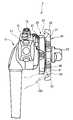
도1 내지 도4는 본 발명의 본 실시 형태의 내시경의 구성에 관한 것이고, 도1은 본 발명의 내시경의 개략 구성을 나타내는 설명도이다. 도1에 도시하는 바와 같이 본 실시 형태에 관한 내시경(1)은, 각종 조작 레버 등이 설치되는 조작부(13)와, 이 조작부(13)로부터 연장하는 가늘고 긴 가요성을 갖는 삽입부(12)와, 조작 부(13)의 측부로부터 연장하고, 라이트 가이드나 신호선 등이 삽입 관통된 유니버설 코드(14)에 의해 주로 구성되어 있다. 또한, 내시경(1)은, 유니버설 코드(14)의 단부에 설치되는 커넥터부(도시하지 않음)를 통해 외부 장치인 광원 장치(도시하지 않음), 신호 처리 장치인 프로세서(도시하지 않음) 등에 착탈 가능하게 접속되도록 되어 있다. 즉, 유니버설 코드(14)는 조작부(13)로부터 연장하고, 내시경(1)과 조합하여 사용하는 외부 장치와 내시경(1)을 접속하기 위한 접속 코드이다.1 to 4 relate to the configuration of the endoscope of the present embodiment of the present invention, and FIG. 1 is an explanatory diagram showing a schematic configuration of the endoscope of the present invention. As shown in FIG. 1, the
내시경(1)의 삽입부(12)는 선단부 부분으로부터 차례로, 조명 광학계 및 관찰 광학계 등이 배치되는 경질의 선단부(9)와, 소정의 방향, 예를 들어 상하 방향 및 좌우 방향의 4방향으로 만곡 가능한 만곡부(10)와, 가요성을 갖고 유연한 가요관부(11)에 의해 구성되어 있다. 또한, 프로세서는 내시경(1)의 선단부(9)의 관찰 광학계로부터의 영상을, 접속된 모니터(도시하지 않음)에 화상 표시시키는 화상 신호를 출력한다.The
내시경(1)의 파지부를 겸하는 조작부(13)의 측면에는, 회전되는 것에 의해 만곡부(10)를 소정의 2방향으로 만곡 동작시키는 제1 만곡 조작 노브(25)와, 제1 만곡 조작 노브(25)와 동일 회전축을 갖고, 제1 만곡 조작 노브(25)에 의한 2방향과 대략 직교하는 2방향으로 만곡 동작시키는 제2 만곡 조작 노브(30)를 갖고 있다. 또한, 조작부(13)는, 프로세서의 영상 기록 기능이나 광원 장치의 광량 조정 등을 원격적으로 행하는 각종 스위치(17), 송기 송액 버튼(15), 흡인 버튼(16)이 각 측면에 배치되고, 삽입부(12)가 연결되는 측에 설치되고, 겸자 채널(18a)을 갖 는 꺾임 방지부(18)가 설치되어 있다. 또한, 부호 21은 상하 만곡 제동 레버를, 부호 22는 좌우 만곡 제동 레버를 나타낸다. 상하 만곡 제동 레버(21)는 제1 만곡 조작 노브(25)의 회전을 제지, 좌우 만곡 제동 레버(22)는 제2 만곡 조작 노브(30)의 회전을 제지하기 위해, 시술자에 의해 소정의 조작이 된다.On the side surface of the
본 실시 형태에 관한 제1 만곡 조작 노브(25) 및 제2 만곡 조작 노브(30)에 대해 도2 및 도3을 참조하면서, 이하 상세하게 설명한다. 도2는, 제1 만곡 조작 노브(25) 및 제2 만곡 조작 노브(30)를 설명하기 위한 도면이다. 도3은, 도1의 조작부(13)를 각종 스위치(17) 방향으로부터 본 상면도이다.The first
도2에 도시하는 바와 같이, 제1 만곡 조작 노브(25)는, 외주측으로 방사형으로 돌출하는 복수의 볼록부, 여기서는 5개의 볼록부(26)를 갖는 대략 원판 형상을 하고 있다. 제1 만곡 조작 노브(25)는, 대략 원판형의 중심점을 회전 중심으로 하여 회전 가능하게 조작부(13)(도1 참조)에 설치되어 있다. 이들 5개의 볼록부(26)는, 각각 제1 만곡 조작 노브(25)의 회전 중심으로부터 외주측을 향해 대략 동일한 소정의 양만큼 돌출하고 있다. 또한, 5개의 볼록부(26)의 회전 중심으로부터 가장 이격된 부분이, 제1 만곡 조작 노브(25)의 최대 외경을 형성하는 돌출 단부 부분으로 된다.As shown in Fig. 2, the first
제1 만곡 조작 노브(25)는 내시경(1)의 만곡부(10)를 2방향으로 만곡 조작하기 위해, 그 중심을 회전 중심으로 하여 회전되지만, 본 실시 형태에 있어서는, 도2의 지면(紙面)을 향해 시계 방향으로 회전되는 것에 의해, 내시경(1)과 전기적으로 접속되는 외부에 있는 모니터의 화면상의 하측 방향으로 내시경(1)의 만곡 부(10)를 만곡시키고, 그 역회전인 반시계 방향의 회전에 의해, 모니터의 화면상의 상측 방향으로 내시경(1)의 만곡부(10)를 만곡시킨다.The first
또한, 도2에 도시하는 바와 같이, 제2 만곡 조작 노브(30)는, 외주측으로 대략 등간격에 있어서 방사형으로 돌출하는 복수의 볼록부, 여기서는 6개의 볼록부(31)를 갖는 대략 원판 형상을 하고 있다. 이 제2 만곡 조작 노브(30)는, 대략 원판형의 중심점을 회전 중심으로 하여 회전 가능하며, 제1 만곡 조작 노브(25)에 중첩하여 조작부(13)에 설치되어 있다.In addition, as shown in FIG. 2, the 2nd
6개의 볼록부(31)는, 각각 제2 만곡 조작 노브(30)의 외주측을 향해, 회전 중심으로부터 대략 동일한 소정의 양만큼 돌출하고 있다. 이들 6개의 볼록부(31) 중 회전 중심으로부터 가장 이격된 부분이, 제2 만곡 조작 노브의 최대 외경을 형성하는 돌출 단부 부분으로 된다. 또한, 제2 만곡 조작 노브(30)의 6개의 볼록부(31)는, 각각의 돌출량이 제1 만곡 조작 노브(25)의 5개의 볼록부(26)의 각각의 돌출량보다도 크다. 즉, 제2 만곡 조작 노브(30)의 회전 중심으로부터 6개의 볼록부(31)의 각각의 돌출 단부 부분까지의 길이는, 제1 만곡 조작 노브(25)의 5개의 볼록부(26)의 각각의 돌출 단부 부분까지의 길이보다도 길다. 또한, 6개의 볼록부(31) 중 돌출 방향의 선단부 부분의 양측에는 회전 방향으로 각각 돌출하는 손잡이부(32)를 갖고 있다. 또한, 제2 만곡 조작 노브(30)는, 6개의 볼록부(31) 중 적어도 1개의 볼록부(31)가 제1 만곡 조작 노브(25)의 5개의 볼록부(26)의 각각의 돌출량보다도 작아도 좋다.The six
도3에 도시하는 바와 같이, 제2 만곡 조작 노브(30)의 6개의 볼록부(31)는, 각각 제1 만곡 조작 노브(25)에 대향하는 면에 단면 형상이 오목형인 오목부(33)를 갖고 있다. 상세하게는, 제2 만곡 조작 노브(30)는, 제1 만곡 조작 노브(25)가 회전되는 것에 의해, 제1 만곡 조작 노브(25)의 돌출 단부 부분이 그리는 원 궤도를 회전축 방향에 있어서, 제2 만곡 조작 노브(30)에 투영한 선의 근방 부분이며, 제1 만곡 조작 노브(25)에 대향하는 볼록부(31)의 면에 오목부(33)를 갖는다. 바꾸어 말하면, 제2 만곡 조작 노브(30)의 볼록부(31)와 제1 만곡 조작 노브(25)의 볼록부(26)가 중첩된 상태에 있어서, 제2 만곡 조작 노브(30)의 볼록부(31)는, 제1 만곡 조작 노브(25)의 볼록부(26)의 돌출 단부 부분에 근접하는 제1 만곡 조작 노브(25)에 대향하는 면의 일부분이, 회전 중심으로부터의 돌출 방향과 대략 직교하는 방향으로 오목하게 마련되는 오목부(33)를 갖고 있다. 또한, 바꾸어 말하면, 제2 만곡 조작 노브(30)의 볼록부(31)와 제1 만곡 조작 노브(25)의 볼록부(26)가 중첩된 상태에 있어서, 오목부(33)는, 제1 만곡 조작 노브(25)의 볼록부(26)의 돌출 단부 부분에 대향하는 제2 만곡 조작 노브(30)의 볼록부(31)의 면의 근방 부분에 마련되는 단면이 오목형인 홈이다. 이 근방 부분은, 예를 들어 볼록부(26)의 돌출 단부 부분을 압박하여 제1 만곡 조작 노브(25)를 회전 조작하는 손가락에 의해 그려지는 원 궤도를 제2 만곡 조작 노브(30)의 표면에 회전축 방향으로 투영한 선이 포함되는 부분이다. 따라서, 이러한 근방 부분에 오목부(33)를 마련한 제2 만곡 조작 노브(30)는, 이와 같이 제1 만곡 조작 노브(25)를 회전 조작하는 손가락을 오목부(33) 내에 통과시키고, 이에 의해, 이 회전 조작하는 손가락을 회피할 수 있다. 또한, 오목부(33)는, 예를 들어 20 ㎜의 오목홈이다.As shown in FIG. 3, the six
제2 만곡 조작 노브(30)는 내시경(1)의 만곡부(10)를 2방향으로 만곡 조작하기 위해 회전되고, 제1 만곡 조작 노브(25)의 회전축과 동일 회전축을 갖는다. 또한, 제2 만곡 조작 노브(30)는, 본 실시 형태에 있어서는 도2의 지면을 향해 시계 방향으로 회전되는 것에 의해, 모니터의 화면상의 우측 방향으로 내시경(1)의 만곡부(10)를 만곡시키고, 그 반대인 반시계 방향의 회전에 의해, 모니터의 화면상의 좌측 방향에 내시경(1)의 만곡부(10)를 만곡시킨다.The second
제1 만곡 조작 노브(25)의 볼록부(26)와 제2 만곡 조작 노브(30)의 볼록부(31)의 개수가 다르기 때문에, 제1 만곡 조작 노브(25)의 5개의 볼록부(26)의 1개가, 제2 만곡 조작 노브(30)의 6개의 볼록부(31)의 1개와 각각 동일 돌출 방향의 위치에 있어서도, 반드시 제1 만곡 조작 노브(25)의 5개의 오목부 중 어느 한쪽에 제2 만곡 조작 노브(30)의 볼록부(31) 중 어느 하나가 위치하고 있다.Since the number of the
다음에 시술자에 의해 조작부(13)의 제1 만곡 조작 노브(25) 및 제2 만곡 조작 노브(30)가 회전 조작되는 동작을 이하에 설명한다. 우선, 시술자는 한쪽의 손에 의해 조작부(13)를 파지하고, 제1 만곡 조작 노브(25) 및 제2 만곡 조작 노브(30)를 회전 조작한다. 그러면, 제1 만곡 조작 노브(25) 및 제2 만곡 조작 노브(30)가 회전되는 것에 의해, 삽입부(12)의 만곡부(10)는 원하는 방향으로 만곡 동작된다. 즉, 시술자는 예를 들어 도3에 도시하는 바와 같이, 제1 만곡 조작 노브(25)의 볼록부(26)의 돌출 단부 부분을 손가락(100)에 의해 압박하면서 제1 만곡 조작 노브(25)의 회전 조작을 한다. 그러면, 내시경(1)의 선단부(9)는 제1 만곡 조작 노브(25)의 회전에 맞추어 2방향, 여기서는 모니터 화면상의 상하 방향으로 만곡 조작이 된다.Next, an operation in which the first
도3에 도시하는 바와 같이, 제1 만곡 조작 노브(25)의 회전 조작을 하고 있는 시술자의 손가락(100)이 압박하고 있는 볼록부(26)와 제2 만곡 조작 노브(30) 중 어느 한쪽의 볼록부(31)가 중첩되었을 때, 손가락(100)의 선단부 부분은, 볼록부(31)의 오목부(33)에 들어가기 때문에 제2 만곡 조작 노브(30)에 대략 접촉하지 않는다. 그로 인해, 시술자는 제1 만곡 조작 노브(25)의 회전 조작시에 제2 만곡 조작 노브(30)가 방해로 되지 않고, 원활하게 제1 만곡 조작 노브(25)의 회전 조작을 행할 수 있다. 또한, 제1 만곡 조작 노브(25)는, 볼록부(26)의 돌출 단부 부분이 주로 엄지에 의해 압박되어 회전 조작되는 경우가 많지만, 엄지로 한정하지 않고 어떠한 손가락에 의해 회전 조작되어도 좋다.As shown in Fig. 3, either one of the
또한, 시술자는 조작부(13)를 파지하고 있는 손의 손가락, 예를 들어 중지 등을 제2 만곡 조작 노브(30)의 볼록부(31)에 걸어 회전 조작을 한다. 그러면, 내시경(1)의 선단부(9)는 제2 만곡 조작 노브(30)의 회전에 맞추어 2방향, 여기서는 모니터 화면상의 좌우 방향으로 만곡 조작이 된다. 제2 만곡 조작 노브(30)의 볼록부(31)는, 도2에 도시한 바와 같이 선단부 부분에 손잡이부(32)를 갖고 있다. 그로 인해, 시술자는 제2 만곡 조작 노브(30)를 회전 조작하고 있는 중지 등이 볼록부(31)의 손잡이부(32)에 걸려 확실히 유지되기 때문에, 제2 만곡 조작 노브(30)의 회전을 용이하게 행할 수 있다. 또한, 시술자는 조작부(13)를 파지하고 있는 손의 중지에 의해 조작부(13)의 일측면에 설치되는 송기 송액 버튼(15) 또는 흡인 버튼(16) 등을 조작하는 경우, 제2 만곡 조작 노브(30)의 6개의 볼록부(31) 중 어 느 한쪽에 검지, 약지 또는 소지를 걸어 제2 만곡 조작 노브(30)를 회전 조작해도 좋다. 즉, 제2 만곡 조작 노브(30)의 회전량에 맞추어, 시술자는 제2 만곡 조작 노브(30)의 6개의 볼록부(31)와 그 조작을 행하는 손가락을 자유롭게 선택함으로써, 내시경(1)의 만곡부(10)를 원하는 만곡량에 있어서의 만곡 조작을 가능하게 변화시킬 수 있다.Moreover, the practitioner rotates the finger of the hand holding the
이와 같이 하여, 시술자는 한쪽 손, 즉 조작부(13)를 파지하고 있는 손의 각종 손가락에 의해 적절하게, 삽입부(12)의 선단부(9)를 원하는 방향을 향하게 하는 만곡부(10)의 만곡 동작을 시키기 위한, 제1 만곡 조작 노브(25) 및 제2 만곡 조작 노브(30)의 회전 조작을 용이하게 행할 수 있다.In this way, the operator can bend the
이상의 결과, 본 실시 형태에 관한 내시경(1)에 따르면, 제2 만곡 조작 노브(30)의 회전 중심으로부터 6개의 볼록부(31)의 각각의 돌출 단부 부분까지의 길이가 제1 만곡 조작 노브(25)의 5개의 볼록부(26)의 각각의 돌출 단부 부분까지의 길이보다도 길기 때문에, 시술자는 제2 만곡 조작 노브(30)를 회전 조작할 때, 제1 만곡 조작 노브(25)의 볼록부(26)가 방해되지 않고, 용이하게 제2 만곡 조작 노브(30)를 회전 조작할 수 있다.As a result of the above, according to the
또한, 제1 만곡 조작 노브(25)의 회전 조작을 하고 있는 시술자의 손가락(100)은, 압박하고 있는 볼록부(26)와 제2 만곡 조작 노브(30) 중 어느 한쪽의 볼록부(31)가 중첩되어도, 손가락(100)의 선단부 부분이 제2 만곡 조작 노브(30)에 대략 접촉하지 않는다. 그로 인해, 시술자는 제2 만곡 조작 노브(30)가 방해로 되지 않고, 원활하게 제1 만곡 조작 노브(25)의 회전 조작을 행할 수 있다. 또한, 제2 만곡 조작 노브(30)의 볼록부(31)가 선단부 부분에 손잡이부(32)를 갖고 있기 때문에, 시술자는 제2 만곡 조작 노브(30)를 회전 조작하고 있는 중지 등이 볼록부(31)의 손잡이부(32)에 걸려 확실히 유지되기 때문에, 제2 만곡 조작 노브(30)의 회전을 용이하게 행할 수 있다.Moreover, the
따라서, 시술자는 손의 대소를 불문하고, 조작부를 파지하고 있는 쪽의 손에 의해서만 내시경(1)의 만곡부(10)의 만곡 조작이 용이하게 되는 것에 의해, 내시경(1)의 선단부 부분을 원하는 방향으로 용이하게 향하게 할 수 있기 때문에, 다른 쪽의 손이 자유로워진다. 이와 같이 하여, 시술자는 환자의 체강 내의 피검 부위를 관찰하기 위해, 피검 부위까지의 삽입시 및 도달시에 내시경의 선단부 부분을 원하는 방향을 향하게 할 때, 내시경의 삽입부가 대장 등의 연동 운동에 의해 항문측으로 밀어 복귀되는 것을 방지하기 위해, 내시경의 삽입부를 다른 쪽의 손에 의해 유지해 둘 수 있다. 따라서, 상술한 바와 같은 때, 시술자는 1세트의 만곡 조작 노브를 한쪽 손에 의해 용이하게 조작할 수 있다.Therefore, the operator can easily bend the
또한, 도4에 도시하는 바와 같이, 내시경(1a)의 제2 만곡 조작 노브(40)에 착탈 가능한 내시경용 만곡 조작 보조 부재인 어태치먼트 노브(30a)를 사용해도 좋다. 이 어태치먼트 노브(30a)는, 상술한 제2 만곡 조작 노브(30)와 상당하는 볼록부(31)를 갖고, 도5에 도시하는 바와 같이 제2 만곡 조작 노브(40)와 대략 동일 형상의 결합용의 함몰인 끼움 장착부(37)를 갖는다. 이 어태치먼트 노브(30a)의 끼움 장착부(37)는, 제2 만곡 조작 노브(40)에 결합시키는 것에 의해 어태치먼트 노브(30a)와 제2 만곡 조작 노브(40)가 끼워 장착된다. 그 결과, 내시경(1)은 시술 자의 각종 용도 및 각종 상황에 있어서 선택적으로 어태치먼트 노브(30a)를 착탈하여 구분하여 사용할 수 있다. 또한, 이 내시경(1)은, 도4에 도시하는 내시경(1a)의 제2 만곡 조작 노브(40)에 어태치먼트 노브(30a)를 설치한 것이다. 이러한 어태치먼트 노브(30a)를 설치한 제2 만곡 조작 노브(40)는, 상술한 제2 만곡 조작 노브(30)와 같은 기능을 갖는다. 시술자는 제2 만곡 조작 노브(40)에 설치한 어태치먼트 노브(30a)를 이용하여 회전 조작하는 것에 의해, 상술한 제2 만곡 조작 노브(30)의 경우와 마찬가지로, 이 제2 만곡 조작 노브(40)를 회전 조작할 수 있다.In addition, as shown in FIG. 4, you may use the
또한, 상술한 설명에 있어서는, 제1 만곡 조작 노브(25) 또는 제2 만곡 조작 노브(30)를 회전 조작하는 손가락을 엄지 또는 중지로 설명했지만, 시술자가 각각의 만곡 조작 노브를 조작하기 쉬운 손가락을 임의로 선택해도 좋다.In addition, in the above-mentioned description, although the finger which rotates the 1st
(제2 실시 형태)(2nd embodiment)
이하, 도면을 참조하여 본 실시 형태를 설명한다. 또한, 본 실시 형태는 제1 실시 형태에 관한 내시경(1)의 변형예이며, 제1 실시 형태의 내시경(1)과 동일 구성 요소에 대해서는, 동일한 부호를 붙여 설명은 생략한다. 도6은, 본 실시 형태의 내시경의 개략 구성을 나타내는 설명도이다. 도7은, 제1 만곡 조작 노브(25) 및 제2 만곡 조작 노브(30b)를 설명하기 위한 도면이다.EMBODIMENT OF THE INVENTION Hereinafter, this embodiment is described with reference to drawings. In addition, this embodiment is a modification of the
도6에 도시하는 바와 같이, 제1 실시 형태와 마찬가지로 제2 만곡 조작 노브(30b)는 외주측으로 대략 등간격에 있어서 방사형으로 돌출하는 복수의 볼록부, 여기서는, 도7에 도시하는 5개의 볼록부(31)와 1개의 볼록부(34)를 갖는 대략 원판 형상을 하고 있다. 이 제2 만곡 조작 노브(30b)는, 제1 실시 형태와 마찬가지로 대략 원판형의 중심점을 회전 중심으로 하여 회전 가능하며, 제1 만곡 조작 노브(25)에 중첩하여 조작부(13)에 설치되어 있다.As shown in FIG. 6, the 2nd
도7에 도시하는 바와 같이, 제2 만곡 조작 노브(30b)는, 5개의 볼록부(31)가 각각 제2 만곡 조작 노브(30b)의 외주측을 향해 회전 중심으로부터 대략 동일한 소정의 양만큼 돌출하고 있다. 또한, 제2 만곡 조작 노브(30b)는 5개의 볼록부(31)와는 다른 볼록부(34)를 갖고, 이 볼록부(34)가 제2 만곡 조작 노브(30b)의 외주측을 향해, 5개의 볼록부(31)의 회전 중심으로부터 돌출한 양보다도 작은 회전 중심으로부터의 소정의 양만큼 돌출하고 있다.As shown in Fig. 7, the second
또한, 제2 만곡 조작 노브(30b)의 볼록부(34)는, 그 돌출량이 제1 만곡 조작 노브(25)의 5개의 볼록부(26)의 각각의 돌출량보다도 작다. 즉, 제2 만곡 조작 노브(30b)의 회전 중심으로부터 볼록부(34)의 돌출 단부 부분까지의 길이는, 제1 만곡 조작 노브(25)의 5개의 볼록부(26)의 각각의 돌출 단부 부분까지의 길이보다도 짧다. 또한, 이 볼록부(34)는 1개로 한정하는 않고, 복수의 볼록부(34)를 제2 만곡 조작 노브(30b)에 설치되어도 좋다. 이때, 제2 만곡 조작 노브(30b)는 적어도 1개의 볼록부(31)를 갖는 것으로 한다.Moreover, the protrusion amount of the
제1 실시 형태와 마찬가지로, 제2 만곡 조작 노브(30b)의 5개의 볼록부(31)는, 각각 도3에 도시한 제1 만곡 조작 노브(25)에 대향하는 면에 단면 형상이 오목형인 오목부(33)를 갖고 있다. 즉, 제2 만곡 조작 노브(30b)는, 제1 만곡 조작 노브(25)가 회전되는 것에 의해 제1 만곡 조작 노브(25)의 돌출 단부 부분이 그리는 원 궤도를 회전축 방향에 있어서, 제2 만곡 조작 노브(30b)에 투영한 선의 근방 부분이며, 제1 만곡 조작 노브(25)에 대향하는 볼록부(31)의 면에 오목부(33)를 갖는다.In the same manner as in the first embodiment, the five
또한, 도6에 도시하는 제1 만곡 조작 노브(25) 및 제2 만곡 조작 노브(30b)의 상태는, 제2 만곡 조작 노브(30b)의 볼록부(34)가 내시경(1)과 조합하여 사용하는 외부 장치와 내시경(1)을 접속하고 있는 유니버설 코드(14)측을 향해 돌출하고 있는 상태를 나타내고, 이 상태에 있어서, 내시경(1)의 만곡부(10)(도1 참조)는 대략 직선의 상태이다. 구체적으로는, 만곡부(10)가 대략 직선의 상태인 경우, 제2 만곡 조작 노브(30b)의 볼록부(34)는, 도6, 도7에 도시하는 바와 같이 조작부(13)를 파지하는 시술자로부터 보아 전방측의 볼록부(26)에 중첩되도록 위치한다.In addition, as for the state of the 1st
제1 실시 형태와 마찬가지로, 시술자는 한쪽의 손에 의해 조작부(13)를 파지하여, 제1 만곡 조작 노브(25) 및 제2 만곡 조작 노브(30b)를 회전 조작하고, 삽입부(12)의 만곡부(10)를 원하는 방향으로 만곡 동작한다. 또한, 시술자는 접속 코드인 유니버설 코드(14)가 설치되는 측을 전방으로 하여 조작부(13)를 파지하고, 내시경(1)에 있어서의 각종 조작을 행한다. 이때, 시술자는 제1 만곡 조작 노브(25)를 예를 들어 엄지에 의해 압박 또는 걸어 회전 조작한다. 제1 만곡 조작 노브(25)는, 특히 유니버설 코드(14)측의 볼록부(26)가 시술자의 엄지에 의해 압박 또는 걸리는 경향이 있다.Similarly to the first embodiment, the practitioner grips the
또한, 제1 만곡 조작 노브(25)를 회전 조작하는 손가락은 엄지로 한정하지 않고, 시술자가 제1 만곡 조작 노브를 조작하기 쉬운 손가락을 임의로 선택해도 좋 다.In addition, the finger which rotates the 1st
따라서, 유니버설 코드(14)측의 제2 만곡 조작 노브(30b)의 볼록부(34)의 돌출량이 제1 만곡 조작 노브(25)의 돌출량보다도 작기 때문에, 시술자의 엄지는 제2 만곡 조작 노브(30b)의 볼록부(34)에 대략 접촉하지 않고 제1 만곡 조작 노브(25)의 볼록부(26)를 용이하게 압박 또는 걸린다. 그로 인해, 시술자는 제1 만곡 조작 노브(25)를 회전 조작할 때, 제2 만곡 조작 노브(30b)의 볼록부(34)가 방해되지 않고, 용이하게 제1 만곡 조작 노브(25)를 회전 조작할 수 있다. 따라서, 시술자는 제1 만곡 조작 노브(25)의 회전 조작이 하기 쉬워져, 삽입부(12)의 만곡부(10)를 모니터 화면상의 상하 방향으로의 만곡 조작이 하기 쉬워진다.Therefore, since the protrusion amount of the
이상의 결과, 제1 실시 형태의 효과에 부가하여, 또한 제1 만곡 조작 노브(25)의 회전 조작이 하기 쉬운 내시경(1)을 실현할 수 있다. 또한, 본 제2 실시 형태에 관한 내시경(1)은 제2 만곡 조작 노브(30b)의 볼록부(34)를 소정의 기준 위치, 예를 들어 도6에 도시하는 바와 같이 유니버설 코드(14)를 향해 돌출한 상태가 되는 위치에 맞추는 것에 의해, 만곡부(10)를 대략 직선의 상태로 용이하게 조정할 수 있다. 따라서, 시술자는 이러한 기준 위치에 대해 볼록부(34)를 맞추는 것에 의해, 만곡부(10)가 환자의 체강 내에 삽입된 경우라도, 만곡부(10)를 대략 직선의 상태로 용이하게 조정할 수 있고, 또한 이러한 기준 위치와 볼록부(34)의 위치 관계를 확인하는 것에 의해, 예를 들어 체강 내에 삽입한 만곡부(10)의 만곡 상태의 정도를 용이하게 추측할 수 있다.As a result of this, in addition to the effect of 1st Embodiment, the
또한, 본 실시 형태의 제2 만곡 조작 노브(30b)는, 제1 실시 형태에 있어서 기재한 어태치먼트 타입(도4 및 도5 참조)으로 해도 좋다. 또한, 제1 실시 형태 및 제2 실시 형태의 내시경(1)의 제1 만곡 조작 노브(25) 및 제2 만곡 조작 노브(30, 30b)는, 내시경(1)의 조작부(13)의 일측면에 착탈 가능한 1세트의 만곡 조작 노브라도 좋다.In addition, you may make the 2nd
이상과 같이, 본 발명에 관한 내시경 및 내시경용 만곡 조작 보조 부재는 체강 내의 피검 부위의 관찰 또는 각종 의료 처치에 유용하고, 특히 이러한 피검 부위의 관찰 또는 각종 의료 처치를 행하기 위해 체강 내에 삽입하는 삽입부의 만곡 조작을 용이하게 행할 수 있는 것으로서 적합하다.As described above, the endoscope and the endoscope bending manipulation assistance member according to the present invention are useful for observing a test site in a body cavity or for various medical treatments, and in particular, an insert inserted into the body cavity for observing such a test site or for performing various medical treatments. It is suitable as it can easily perform negative curvature operation.
Claims (13)
Translated fromKoreanPriority Applications (1)
| Application Number | Priority Date | Filing Date | Title |
|---|---|---|---|
| KR1020067026397AKR100881811B1 (en) | 2004-06-17 | 2005-06-17 | Endoscope, endoscope bending operation aid and one set of bending operation knob |
Applications Claiming Priority (2)
| Application Number | Priority Date | Filing Date | Title |
|---|---|---|---|
| JPJP-P-2004-00180190 | 2004-06-17 | ||
| KR1020067026397AKR100881811B1 (en) | 2004-06-17 | 2005-06-17 | Endoscope, endoscope bending operation aid and one set of bending operation knob |
Publications (2)
| Publication Number | Publication Date |
|---|---|
| KR20070023738A KR20070023738A (en) | 2007-02-28 |
| KR100881811B1true KR100881811B1 (en) | 2009-02-03 |
Family
ID=41346310
Family Applications (1)
| Application Number | Title | Priority Date | Filing Date |
|---|---|---|---|
| KR1020067026397AExpired - Fee RelatedKR100881811B1 (en) | 2004-06-17 | 2005-06-17 | Endoscope, endoscope bending operation aid and one set of bending operation knob |
Country Status (1)
| Country | Link |
|---|---|
| KR (1) | KR100881811B1 (en) |
Cited By (2)
| Publication number | Priority date | Publication date | Assignee | Title |
|---|---|---|---|---|
| KR102351709B1 (en) | 2020-09-18 | 2022-01-17 | 주식회사 메디인테크 | Electrically driven endoscope |
| KR20240159301A (en) | 2023-04-28 | 2024-11-05 | 주식회사 메디인테크 | Controller knob device for endoscope |
Families Citing this family (3)
| Publication number | Priority date | Publication date | Assignee | Title |
|---|---|---|---|---|
| KR101030371B1 (en) | 2009-04-27 | 2011-04-20 | 국립암센터 | Endoscopic adjustment device for minimally invasive surgery |
| KR101030427B1 (en) | 2009-04-28 | 2011-04-20 | 국립암센터 | Endoscopic adjustment device for minimally invasive surgery |
| EP4374766B1 (en)* | 2022-11-22 | 2025-07-02 | Ambu A/S | Endoscope with control wheel and visualization system |
Citations (2)
| Publication number | Priority date | Publication date | Assignee | Title |
|---|---|---|---|---|
| JPH02141401U (en)* | 1989-04-28 | 1990-11-28 | ||
| KR20020038662A (en)* | 2002-04-30 | 2002-05-23 | 이기학 | Endoscope apparatus and method for processing suction and irrigation |
- 2005
- 2005-06-17KRKR1020067026397Apatent/KR100881811B1/ennot_activeExpired - Fee Related
Patent Citations (2)
| Publication number | Priority date | Publication date | Assignee | Title |
|---|---|---|---|---|
| JPH02141401U (en)* | 1989-04-28 | 1990-11-28 | ||
| KR20020038662A (en)* | 2002-04-30 | 2002-05-23 | 이기학 | Endoscope apparatus and method for processing suction and irrigation |
Cited By (3)
| Publication number | Priority date | Publication date | Assignee | Title |
|---|---|---|---|---|
| KR102351709B1 (en) | 2020-09-18 | 2022-01-17 | 주식회사 메디인테크 | Electrically driven endoscope |
| WO2022059848A1 (en) | 2020-09-18 | 2022-03-24 | 주식회사 메디인테크 | Motor-driven endoscope |
| KR20240159301A (en) | 2023-04-28 | 2024-11-05 | 주식회사 메디인테크 | Controller knob device for endoscope |
Also Published As
| Publication number | Publication date |
|---|---|
| KR20070023738A (en) | 2007-02-28 |
Similar Documents
| Publication | Publication Date | Title |
|---|---|---|
| JP4615906B2 (en) | Endoscope and endoscope bending operation auxiliary member | |
| US6554766B2 (en) | Endoscope device | |
| JP3600194B2 (en) | Endoscope | |
| CN101106932B (en) | endoscope | |
| US20150313450A1 (en) | Stopper for the Cables of a Bending Section of An Endoscope | |
| CN111212589B (en) | Endoscope system | |
| US20140012087A1 (en) | Endoscope | |
| WO2015168664A1 (en) | Stopper for the cables of a bending section of an endoscope | |
| US9635999B2 (en) | Endoscope | |
| JP2005131211A (en) | Externally mounted channel for endoscope | |
| JP2001095747A (en) | Electronic endoscope | |
| US9770158B2 (en) | Holding mechanism for endoscope guide member, and endoscope | |
| CN111295123B (en) | Medical device | |
| JP2002330924A (en) | Endoscope | |
| KR100881811B1 (en) | Endoscope, endoscope bending operation aid and one set of bending operation knob | |
| JP5702032B2 (en) | Endoscope | |
| JP4445779B2 (en) | Endoscope and endoscope bending operation auxiliary member | |
| JP2004283618A (en) | Endoscope | |
| JP2003204926A (en) | Endoscope | |
| WO2023163210A1 (en) | Medical manipulator system and operating device | |
| JP6305316B2 (en) | Endoscope | |
| JP3722732B2 (en) | Endoscope | |
| US20180042455A1 (en) | Attachment unit | |
| JP2019010363A (en) | Remote controller for endoscope |
Legal Events
| Date | Code | Title | Description |
|---|---|---|---|
| A201 | Request for examination | ||
| PA0105 | International application | St.27 status event code:A-0-1-A10-A15-nap-PA0105 | |
| PA0201 | Request for examination | St.27 status event code:A-1-2-D10-D11-exm-PA0201 | |
| P11-X000 | Amendment of application requested | St.27 status event code:A-2-2-P10-P11-nap-X000 | |
| P13-X000 | Application amended | St.27 status event code:A-2-2-P10-P13-nap-X000 | |
| PG1501 | Laying open of application | St.27 status event code:A-1-1-Q10-Q12-nap-PG1501 | |
| E902 | Notification of reason for refusal | ||
| PE0902 | Notice of grounds for rejection | St.27 status event code:A-1-2-D10-D21-exm-PE0902 | |
| R17-X000 | Change to representative recorded | St.27 status event code:A-3-3-R10-R17-oth-X000 | |
| P11-X000 | Amendment of application requested | St.27 status event code:A-2-2-P10-P11-nap-X000 | |
| P13-X000 | Application amended | St.27 status event code:A-2-2-P10-P13-nap-X000 | |
| E902 | Notification of reason for refusal | ||
| PE0902 | Notice of grounds for rejection | St.27 status event code:A-1-2-D10-D21-exm-PE0902 | |
| P11-X000 | Amendment of application requested | St.27 status event code:A-2-2-P10-P11-nap-X000 | |
| P13-X000 | Application amended | St.27 status event code:A-2-2-P10-P13-nap-X000 | |
| E701 | Decision to grant or registration of patent right | ||
| PE0701 | Decision of registration | St.27 status event code:A-1-2-D10-D22-exm-PE0701 | |
| GRNT | Written decision to grant | ||
| PR0701 | Registration of establishment | St.27 status event code:A-2-4-F10-F11-exm-PR0701 | |
| PR1002 | Payment of registration fee | St.27 status event code:A-2-2-U10-U12-oth-PR1002 Fee payment year number:1 | |
| PG1601 | Publication of registration | St.27 status event code:A-4-4-Q10-Q13-nap-PG1601 | |
| PR1001 | Payment of annual fee | St.27 status event code:A-4-4-U10-U11-oth-PR1001 Fee payment year number:4 | |
| FPAY | Annual fee payment | Payment date:20130111 Year of fee payment:5 | |
| PR1001 | Payment of annual fee | St.27 status event code:A-4-4-U10-U11-oth-PR1001 Fee payment year number:5 | |
| FPAY | Annual fee payment | Payment date:20140107 Year of fee payment:6 | |
| PR1001 | Payment of annual fee | St.27 status event code:A-4-4-U10-U11-oth-PR1001 Fee payment year number:6 | |
| FPAY | Annual fee payment | Payment date:20150105 Year of fee payment:7 | |
| PR1001 | Payment of annual fee | St.27 status event code:A-4-4-U10-U11-oth-PR1001 Fee payment year number:7 | |
| LAPS | Lapse due to unpaid annual fee | ||
| PC1903 | Unpaid annual fee | St.27 status event code:A-4-4-U10-U13-oth-PC1903 Not in force date:20160129 Payment event data comment text:Termination Category : DEFAULT_OF_REGISTRATION_FEE | |
| R18-X000 | Changes to party contact information recorded | St.27 status event code:A-5-5-R10-R18-oth-X000 | |
| PC1903 | Unpaid annual fee | St.27 status event code:N-4-6-H10-H13-oth-PC1903 Ip right cessation event data comment text:Termination Category : DEFAULT_OF_REGISTRATION_FEE Not in force date:20160129 | |
| P22-X000 | Classification modified | St.27 status event code:A-4-4-P10-P22-nap-X000 |