KR100880559B1 - Intermittent elements, circuits and devices provided with them, and methods of assembling intermittent elements - Google Patents
Intermittent elements, circuits and devices provided with them, and methods of assembling intermittent elementsDownload PDFInfo
- Publication number
- KR100880559B1 KR100880559B1KR1020050045017AKR20050045017AKR100880559B1KR 100880559 B1KR100880559 B1KR 100880559B1KR 1020050045017 AKR1020050045017 AKR 1020050045017AKR 20050045017 AKR20050045017 AKR 20050045017AKR 100880559 B1KR100880559 B1KR 100880559B1
- Authority
- KR
- South Korea
- Prior art keywords
- intermittent
- abandoned
- current
- pulse current
- payment
- Prior art date
- Legal status (The legal status is an assumption and is not a legal conclusion. Google has not performed a legal analysis and makes no representation as to the accuracy of the status listed.)
- Expired - Fee Related
Links
Images


Classifications
- H—ELECTRICITY
- H01—ELECTRIC ELEMENTS
- H01H—ELECTRIC SWITCHES; RELAYS; SELECTORS; EMERGENCY PROTECTIVE DEVICES
- H01H35/00—Switches operated by change of a physical condition
- H01H35/14—Switches operated by change of acceleration, e.g. by shock or vibration, inertia switch
- H01H35/144—Switches operated by change of acceleration, e.g. by shock or vibration, inertia switch operated by vibration
- H—ELECTRICITY
- H01—ELECTRIC ELEMENTS
- H01H—ELECTRIC SWITCHES; RELAYS; SELECTORS; EMERGENCY PROTECTIVE DEVICES
- H01H35/00—Switches operated by change of a physical condition
- H01H35/14—Switches operated by change of acceleration, e.g. by shock or vibration, inertia switch
- H—ELECTRICITY
- H01—ELECTRIC ELEMENTS
- H01H—ELECTRIC SWITCHES; RELAYS; SELECTORS; EMERGENCY PROTECTIVE DEVICES
- H01H11/00—Apparatus or processes specially adapted for the manufacture of electric switches
Landscapes
- Brushes (AREA)
- Breakers (AREA)
- Body Washing Hand Wipes And Brushes (AREA)
- Electrotherapy Devices (AREA)
- Switches Operated By Changes In Physical Conditions (AREA)
Abstract
Translated fromKoreanDescription
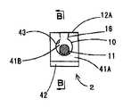
Translated fromKorean도 1은, 본 발명의 실시예1에 따른 단속소자의 측면도이고, 일부를 도 2에 나타내는 B - B선에 따른 단면으로 나타내는 도면이다.1 is a side view of an interruption device according to a first embodiment of the present invention, a part of which is shown in cross section along the line B-B shown in FIG.
도 2는, 도 1에 나타내는 A - A선에 따른 단면도이다.FIG. 2 is a cross-sectional view taken along a line A-A shown in FIG. 1.
도 3은, 본 발명의 실시예1에 따른 단속소자를 구비한 회로를 나타내는 도면이다.Fig. 3 is a diagram showing a circuit including an interrupting device according to the first embodiment of the present invention.
도 4는, 도 3에 나타내는 회로가 발생시키는 불규칙한 펄스전류의 일례를 나타내는 도면이다.4 is a diagram illustrating an example of an irregular pulse current generated by the circuit shown in FIG. 3.
도 5는, 도 3에 나타내는 회로의 일부를 구비한 회로기판의 모식도이다.FIG. 5 is a schematic diagram of a circuit board including a part of the circuit shown in FIG. 3.
도 6은, 도 5에 나타내는 회로기판의 측면도이다.FIG. 6 is a side view of the circuit board shown in FIG. 5.
도 7은, 도 5 및 도 6에 나타내는 회로기판이 설치된 펄스전류 발생장치로서의 이온 칫솔의 분해평면도이다.FIG. 7 is an exploded plan view of an ion toothbrush as a pulse current generator provided with the circuit board shown in FIGS. 5 and 6.
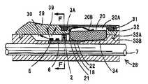
도 8은, 도 7에 나타내는 E - E선에 따른 단면도이다.FIG. 8 is a cross-sectional view taken along the line E-E shown in FIG. 7.
도 9는, 도 8에 나타내는 F - F선에 따른 단면도이다.FIG. 9 is a cross-sectional view taken along the line F-F shown in FIG. 8.
도 10(1)은, 본 발명의 실시예1에 따른 단속소자를 제조하는 공정의 일부를 나타내는 모식도이다.Fig. 10 (1) is a schematic diagram showing a part of the process of manufacturing the interruption device according to the first embodiment of the present invention.
도 10(2)는, 도 10(1)의 일부 확대단면도이다.FIG. 10 (2) is a partially enlarged cross-sectional view of FIG. 10 (1).
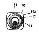
도 11은, 본 발명의 실시예2에 따른 단속소자의 단면도이다.11 is a cross-sectional view of an interruption device according to a second embodiment of the present invention.
도 12는, 도 11에 나타내는 C - C선에 따른 단면도이다.FIG. 12 is a cross-sectional view taken along the line CC of FIG. 11.
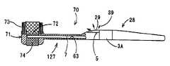
도 13은, 본 발명의 실시예3에 따른 펄스전류 발생장치로서의 미안기의 측면도이고, 일부를 단면으로 나타내는 도면이다.Fig. 13 is a side view of a facial device as a pulse current generating device according to a third embodiment of the present invention, showing a part of it in cross section.
도 14는, 본 발명의 실시예4에 따른 펄스전류 발생장치로서의 맛사지기의 측면도이고, 일부를 단면으로 나타내는 도면이다.Fig. 14 is a side view of a massaging machine as a pulse current generating device according to a fourth embodiment of the present invention, showing a portion in cross section.
도 15는, 본 발명의 실시예5에 따른 펄스전류 발생장치로서의 이온 전동칫솔의 단면모식도이다.Fig. 15 is a schematic cross-sectional view of an ion powered toothbrush as a pulse current generating device according to a fifth embodiment of the present invention.
도 16은, 본 발명의 실시예6에 따른 단속소자의 측면도이고, 일부를 도 17에 나타내는 G - G선에 따른 단면으로 나타내는 도면이다.FIG. 16 is a side view of an interruption device according to a sixth embodiment of the present invention, and a portion thereof is shown in cross section along the line G-G shown in FIG.
도 17은, 도 16에 나타내는 단속소자의 우측면도이다.FIG. 17 is a right side view of the control element shown in FIG. 16. FIG.
도 18은, 실시예7에 따른 단속소자의 측면도이고, 일부를 도 17에 나타내는 G - G선에 따른 단면과 같은 단면으로 나타내는 도면이다.FIG. 18 is a side view of an interruption device according to a seventh embodiment, showing a part of the same as a cross section taken along the line G-G shown in FIG.
도 19는, 실시예8에 따른 고전위 불규칙 펄스전류 발생회로를, 이온 칫솔에 사용한 경우를 나타내는 도면이다.Fig. 19 is a diagram showing a case where a high potential irregular pulse current generation circuit according to the eighth embodiment is used for an ion toothbrush.
도 20은, 실시예8에 따른 고전위 불규칙 펄스전류 발생회로를, 맛사지기에 사용한 경우를 나타내는 도면이다.20 is a diagram showing a case where the high potential irregular pulse current generation circuit according to the eighth embodiment is used for a massager.
본 발명은, 회로를 외부로부터의 진동에 따라 불규칙하게 개폐가능한 단속소자, 및 이 단속소자를 구비한 회로, 고전위 불규칙 펄스전류 발생회로, 및 이 회로를 구비하고, 불규칙한 펄스전류를 발생시킬 수 있는 펄스전류 발생장치, 및 고전위 불규칙 펄스전류 발생장치 및 단속소자의 조립방법에 관한 것이다.The present invention provides an intermittent element that can open and close the circuit irregularly in response to vibrations from the outside, and a circuit including the intermittent element, a high potential irregular pulse current generating circuit, and this circuit, and can generate an irregular pulse current. And a method for assembling a high-potential irregular pulse current generator and an intermittent element.
종래부터, 미진동이나 경사 등의 자세변화를 검출할 때에는, 스프링식 스위치나 수은접점 스위치가 있다. 또한, 일본 특허공개 평6 - 290690호 공보에는, 스프링식 스위치나 수은접점 스위치의 탄성열화, 미묘한 조정방법, 자세변화 감도의 낮음, 큰 형상 등의 문제점을 해결시킨 소형 스위치로서, 표면에 도전성을 가지는 구접점을 복수의 전극을 가지는 2장이 대향한 전극판의 사이에 배치하고, 상기 전극판을 유지하는 프레임을 상기 구접점에 둘러 설치한 것을 특징으로 하는 구접점 스위치가 개시되어 있다.Conventionally, when detecting posture changes such as microscopic vibration and inclination, there are spring-type switches and mercury contact switches. In addition, Japanese Patent Laid-Open No. 6-290690 discloses a compact switch that solves problems such as elastic deterioration of a spring-type switch or a mercury contact switch, a delicate adjustment method, low posture change sensitivity, and a large shape. The contact switch which has a contact point is arrange | positioned between the electrode plate which two sheets which have a some electrode, and the said electrode plate holding is provided surrounding the said contact point, The contact point switch characterized by the above-mentioned.
또한, 일본 특허공개 평11 - 73831호 공보에는, 구상 도전체를 사용한 자세검출 기능에 의해, 기기의 자세에 따라 조명의 점등, 및 비점등을 제어하도록 한 스위치 장치가 개시되어 있다. 이 스위치 장치는, 유닛 케이스와, 상기 유닛 케이스내에 소정의 간격을 가지고 대향하여 설치되어 있는 한 쌍의 전극과, 상기 유닛 케이스내의 이동가능하게 수납되어 있는 구상 도전체를 가지고 있으며, 상기 한 쌍의 전극에는, 상기 구상 도전체와 거의 동등한 반경을 가지는 원호상의 전극면을 형성한 구성을 갖추고 있다.Further, Japanese Patent Laid-Open No. Hei 11-73831 discloses a switch device in which the lighting and non-lighting are controlled according to the attitude of the device by the posture detection function using a spherical conductor. The switch device includes a unit case, a pair of electrodes provided to face each other at predetermined intervals in the unit case, and a spherical conductor housed in the unit case so as to be movable. The electrode has a configuration in which an arc-shaped electrode surface having a radius substantially equal to that of the spherical conductor is formed.
그리고 또한, 일본 특허공개 평9 - 108453호 공보에는, 적어도 표면이 도전성인 적어도 한 개의 구체와, 상기 구체를 길이방향으로 이동이 자유롭게 수납하는 케이스로 이루어지며, 상기 케이스의 바닥면의 적어도 일부와, 상기 케이스의 길이방향의 한 쪽의 끝부 부근의 벽면 혹은 길이방향의 끝부 부근에 세워 설치된 내벽면의 적어도 일부는, 각각 단자로서 형성되고, 각 단자는 상기 구체를 개재하여 통전함으로써, 유희자가 스위치를 직접 조작하지 않아도 봉제완구 등의 인형완구를 안거나 눕히거나 하는 것 만으로, 완구의 동작이 변화되는 스위치가 개시되어 있다.Further, Japanese Patent Laid-Open No. 9-108453 includes at least one sphere having a conductive surface at least, and a case for freely storing the sphere in a longitudinal direction, and having at least a portion of a bottom surface of the case. At least a part of the wall surface near one end in the longitudinal direction of the case or the inner wall surface standing up near the end in the longitudinal direction is respectively formed as a terminal, and each terminal is energized through the sphere so that the player switches. There is disclosed a switch in which the operation of the toy is changed only by holding or lying on a doll toy such as a stuffed toy without directly operating the toy.
또한, 일본 특허공개 평2 - 49734호 공보에는, 액체를 분사하는 노즐과, 이 노즐을 지지함과 아울러, 사용자의 손에 의해 파지되는 손잡이부와, 블로킹 발진회로를 포함하는 고전위 발생회로를 구비하여, 이 고전위 발생회로의 출력단의 마이너스 전극을 상기 노즐에 접속하고, 또한 플러스 전극을 상기 손잡이부에 접속한 전기 구강세정 노즐이 개시되어 있다.Further, Japanese Patent Laid-Open No. Hei 2-49734 discloses a high potential generating circuit including a nozzle for injecting liquid, a handle portion held by a user's hand while supporting the nozzle, and a blocking oscillation circuit. The present invention discloses an electric oral cleaning nozzle comprising a negative electrode at the output end of the high potential generating circuit connected to the nozzle and a positive electrode connected to the handle part.
또한, 일본 특허공개 소60 - 253461호 공보에는, 사용자가 파지하는 손잡이부에 고전위 발생회로를 내장하고, 상기 손잡이부 표면에, 상기 고전위 발생회로의 양전극을 노출하여 형성하며, 브러시부에 이 고전위 발생회로의 음전극을 노출하여 형성한 고전위 칫솔이 개시되어 있다.Further, Japanese Patent Laid-Open No. 60-253461 has a high potential generating circuit embedded in a handle part held by a user, and is formed by exposing both electrodes of the high potential generating circuit on a surface of the handle part. A high potential toothbrush formed by exposing a negative electrode of this high potential generating circuit is disclosed.
또한, 종래부터, 저주파전류를 피부의 위로부터 흐르게 하면, 그 자극에 의해, 신경에 정상적인 흥분이 발생하고, 신경의 움직임에 이상이 있으면, 본래의 바른 움직임이 회복되는 것이 알려져 있다. 이것을 해외에서는, 일반적인 저주파요법 으로서, TENS(Transcutaneous Electrical Nerve Stimulation의 약칭 : 경피 전기적 신경자극법)로 불리고 있다. 저주파요법의 주된 생리적 작용은, (1) 운동신경이나 근육에 대한 작용, 맛사지 효과와 운동효과, (2) 자율신경에 대한 작용, 여러가지 만성병에 효과, (3) 지각신경에 대한 작용, 진통효과라고 말해지고 있다.In addition, conventionally, when a low-frequency current flows from above the skin, it is known that the normal excitation occurs in the nerve by the stimulus, and if the nerve movement is abnormal, the original correct movement is restored. Overseas, as a general low frequency therapy, it is called TENS (abbreviation of Transcutaneous Electrical Nerve Stimulation). The main physiological effects of low frequency therapy are: (1) motor and muscle effects, massage and motor effects, (2) autonomic nerves, effects on various chronic diseases, (3) perceptual nerves, analgesic effects It is said.
저주파요법의 대표적인 생리작용으로서는, 「통전시의 음극은 진정작용, 양극은 흥분적 작용을 가진다」고 말해지고 있지만, 최근, 세계 각국의 의학자들의 연구에 의해, 음양의 극성보다 저주파전류의 파형이나 주파수의 변화에 의한 작용의 쪽이 인체에 미치는 좋은 영향이 큰 것으로 알려져 왔다. 즉, 전류의 파형이나 주파수의 변화가, 뇌간으로부터 나오는 엔돌핀이라는 자연적인 진통물질의 분비를 왕성하게 하거나, 척수에 있는 동통을 제어하는 게이트의 움직임에 좋은 영향을 미치는 일 등이 해명되어 오고 있다. 이 때문에, 컴퓨터(마이크로컴퓨터)를 사용하여, 안전하고 유효한 파형이나 주파수를 자동적으로 출력하는 새로운 저주파치료기도 등장하고 있다(예를 들면, 전자치료대사전, 쓰쿠바대학 명예교수·의학박사·스기 야스사부로 감수, 켄유칸 1993년 발행 참조).As a typical physiological action of low frequency therapy, "the negative electrode at the time of energization has a sedation effect, and the positive electrode has an excitatory effect", but recently, the study of medical researchers around the world, the waveform of the low frequency current than the polarity of the positive and negative It has been known that the effect of the change of frequency on the human body has a great effect. In other words, it has been elucidated that changes in the waveform and frequency of the current increase the secretion of a natural analgesic substance called endorphin from the brain stem or have a good effect on the movement of the gate that controls the pain in the spinal cord. For this reason, new low-frequency therapies have also emerged that use computers (microcomputers) to automatically output safe and effective waveforms and frequencies (for example, electronic therapy metabolism, honorary professor, doctor of medicine, Yasuzabu Sugi, University of Tsukuba). Supervised, see Kenyukan 1993).
그리고 또한, 생체에는 물리적인 자극에 대한 습관화 현상이 있어서, 자극을 주어도 그 자극이 같은 자극이면, 상기 자극에 대한 반응이 약해지는 것이 알려져 있다(예를 들면, 전자와 의학, Vol.454, 2004년 7월호, 쓰쿠바 기술단기대학 침구학과교수·의학박사·모리야마 아사마사 참조).In addition, the living body has a habit of physical stimulation, and it is known that the response to the stimulus is weakened even if the stimulus is the same (for example, electronics and medicine, Vol. 454, 2004). July issue, see Professor, Department of Acupuncture, Tsukuba Junior College, Doctor of Medicine, Asamasa Moriyama).
그러나, 일본 특허공개 평6 - 290690호 공보, 일본 특허공개 평11 - 73831호 공보, 일본 특허공개 평9 - 108453호에 기재된 스위치는, 구상 도전체(구접점)를 이동시켜, 이것을 한 쌍의 전극에 접촉시킴으로써, 스위치의 온/오프를 행하는 구성을 갖추고 있기 때문에, 구상 도전체가 이동하기 위한 영역을 확보할 필요가 있고, 소형화 하는 것이 곤란하며, 소비전력이 큼과 아울러, 부품이 고비용으로 되고 있다.However, the switches described in Japanese Patent Application Laid-Open No. Hei 6-290690, Japanese Patent Application Laid-Open No. Hei 11-73831, and Japanese Patent Application Laid-open No. Hei 9-108453 move a spherical conductor (contact point), and this is a pair of switches. Since the switch is turned on and off by contacting the electrode, it is necessary to secure an area for the spherical conductor to move, it is difficult to miniaturize, the power consumption is high, and the parts are expensive. have.
또한, 일본 특허공개 평2 - 49734호 공보 및 일본 특허공개 소60 - 253461호 공보에 기재된 고전위 발생회로 및 고전위 칫솔은, 규칙적인 펄스전류를 발생하는 것이고, 생체(인체)에 부여하는 자극이 일정한 자극(같은 자극)이다. 이 때문에, 비특허문헌2에 기재되어 있는 바와 같이, 물리적인 자극에 대한 습관화 현상이 발생하여, 상기 자극에 대한 반응이 약해져 장기간에 걸쳐 적절한 효과를 얻는 일이 곤란하다.In addition, the high potential generating circuit and the high potential toothbrush described in Japanese Patent Application Laid-Open No. H249734 and Japanese Patent Laid-Open No. 60-253461 generate a regular pulse current, and a stimulus applied to a living body (human body). This is a constant stimulus (same stimulus). For this reason, as described in
또한, 전자치료대사전, 쓰쿠바대학 명예교수·의학박사·스기 야스사부로 감수, 켄유칸 1993년 발행에 기재되어 있는 바와 같이, 저주파전류의 파형이나 주파수를 변화시킴으로써 신체활성화에 유효한 불규칙한 펄스전류를 발생시키도록 한 경우, 상기 불규칙한 펄스전류를 발생시키기 위해 일본 특허공개 평6 - 290690호 공보, 일본 특허공개 평11 - 73831호 공보, 일본 특허공개 평9 - 108453호에 기재된 스위치를 적용하고자 해도, 이들 스위치는 상술한 바와 같이 소형화하는 것이 곤란하기 때문에, 예를 들면, 칫솔의 손잡이 등 좁은 공간에 수용할 수 없다고 하는 결점이 있었다. 또한, 종래의 스위치(예를 들면 펄스 디지털 회로 등)는, 소비전력이 크기 때문에, 예를 들면, 전원으로서 전지를 사용한 경우, 전지의 수명이 짧아지고, 전지를 빈번하게 교환할 필요가 있었다. 그리고 또한, 종래의 스위치는 비용이 높기 때문에, 이것을 수용한 제품(예를 들면, 칫솔 등)의 비용도 증가한다고 하는 문제도 있었다.Furthermore, as described in the Electronic Therapy Dictionary, Emeritus Professor, Doctor of Medicine, Yasu Sabu, University of Tsukuba, and Published in 1993, Kenyukan, the waveform and frequency of the low frequency current were changed to generate an irregular pulse current effective for body activation. In this case, even if the switches described in Japanese Patent Application Laid-open No. Hei 6-290690, Japanese Patent Application Laid-open No. Hei 11-73831 and Japanese Patent Application Laid-open No. Hei 9-108453 are applied to generate the irregular pulse current, these switches are used. Since it is difficult to miniaturize as mentioned above, there existed a fault that it cannot be accommodated in a narrow space, such as a handle of a toothbrush, for example. In addition, since a conventional switch (for example, a pulse digital circuit, etc.) has a large power consumption, for example, when a battery is used as a power source, the battery life is shortened, and the batteries need to be replaced frequently. Moreover, since the conventional switch has high cost, there also exists a problem that the cost of the product (for example, toothbrush etc.) which accommodated this also increases.
본 발명은, 이와 같은 종래의 문제점을 해결하는 것을 과제로 하는 것이며, 소형화가 가능하고, 구조가 단순하며, 소비전력이 작고, 저비용이며, 회로를 불규칙하게 도통 및 절연시킴으로써, 불규칙한 펄스전류를 발생시키는 것이 가능한 단속소자, 이 단속소자를 구비한 회로, 고전위 불규칙 펄스전류 발생회로, 및 이 회로를 구비한 회로기판, 및 이 회로를 구비한 펄스전류 발생장치, 및 고전위 불규칙 펄스전류 발생장치, 및 단속소자의 조립방법을 제공하는 것을 목적으로 한다.SUMMARY OF THE INVENTION The present invention has an object of solving such a conventional problem, and can be miniaturized, simple in structure, low in power consumption, low in cost, and irregularly conducting and insulating circuits, thereby generating an irregular pulse current. An intermittent element capable of making it possible, a circuit provided with the intermittent element, a high potential irregular pulse current generating circuit, and a circuit board provided with the circuit, a pulse current generator provided with the circuit, and a high potential irregular pulse current generator And an assembly method of the intermittent elements.
이 목적을 달성하기 위해, 본 발명은, 지지체에 서로 이간하여 고정된 한 쌍의 고정단자와, 상기 한 쌍의 고정 단자에 대하여 이동가능하고, 상기 이동에 따라 상기 한 쌍의 고정단자에 접촉 혹은 비접촉하며, 이들 고정단자를 도통 혹은 절연시키는 가동부재를 구비하고, 상기 가동부재는, 외부로부터 부여된 진동에 따라 불규칙하게 상기 이동을 행하여, 상기 한 쌍의 고정단자를 불규칙하게 도통 및 절연시키는 단속소자를 제공하는 것이다.In order to achieve this object, the present invention provides a pair of fixed terminals fixed to the supporter and spaced apart from each other, and movable with respect to the pair of fixed terminals, and in contact with the pair of fixed terminals in accordance with the movement. A non-contacting, movable member for conducting or insulating these fixed terminals, wherein said movable member performs said movement irregularly in response to a vibration applied from the outside, thereby intermittently conducting and insulating said pair of fixed terminals. It is to provide an element.
이 구성을 갖춘 단속소자는, 구성이 단순하고, 소형화가 가능함과 아울러, 소비전력이 작고, 저비용이며, 이것을 회로의 소정 위치에 접속하면, 상기 회로를 불규칙하게 도통 및 절연시키는 것이 가능하게 된다.The intermittent element having this structure is simple in structure, small in size, small in power consumption, low in cost, and connected to a predetermined position of the circuit, whereby the circuit can be irregularly connected and insulated.
또한, 이 구성을 갖춘 단속소자는, 외부로부터 부여된 진동에 따라 가동부재 가 불규칙하게 이동을 행하고, 상기 한 쌍의 고정단자를 불규칙하게 도통 및 절연시킨다. 따라서, 상기 도통 및 절연을 반복함으로써 발생하는 펄스전류도 불규칙한 것이 된다. 이 때문에, 상기 이점에 더하여, 신체활성화에 유효한 불규칙한 펄스전류를 간단하게 발생시킬 수 있다.In addition, in the intermittent element with this configuration, the movable member moves irregularly in accordance with the vibration applied from the outside, and the pair of fixed terminals are electrically connected and insulated irregularly. Therefore, the pulse current generated by repeating the above conduction and insulation also becomes irregular. For this reason, in addition to the above advantages, it is possible to simply generate an irregular pulse current effective for body activation.
본 발명에 따른 단속소자에서는, 상기 가동부재를 모든 방향에 대하여 이동가능하게 구성할 수 있다. 이와 같은 구성으로 함으로써, 외부로부터 부여되는 진동이 어떤 방향의 진동이더라도, 상기 가동부재를 불규칙하게 이동시킬 수 있고, 상기 한 쌍의 고정단자를 보다 확실하게 불규칙하게 도통 및 절연시킬 수 있다.In the intermittent element according to the present invention, the movable member can be configured to be movable in all directions. With such a configuration, even if the vibration applied from the outside is in any direction, the movable member can be moved irregularly, and the pair of fixed terminals can be more reliably and irregularly connected and insulated.
또한, 상기 가동부재는, 일단측이 상기 한 쪽의 고정단자에 접촉 혹은 비접촉하고, 타단측이 상기 다른 쪽의 고정단자에 접촉 혹은 비접촉하도록 구성할 수 있다.In addition, the movable member may be configured such that one end side is in contact or non-contact with the one fixed terminal, and the other end side is in contact or non-contact with the other fixed terminal.
그리고 또한, 상기 고정단자는, 상기 가동부재를 헐겁게 관통시키는 관통공을 가지고, 상기 가동부재의 양단이 상기 각 고정단자의 관통공을 헐겁게 관통하여 이루어지도록 구성할 수도 있다. 이 구성의 경우, 관통공에 헐겁게 관통된 가동부재가 외부로부터 부여된 진동에 따라 불규칙하게 움직이고, 관통공을 고정하고 있는 가장자리부에 불규칙하게 접촉하거나, 불규칙하게 떨어지거나 할 수 있다. 따라서, 가동부재는 그 양단이, 한 쌍의 고정단자의 각각의 관통공을 획정하고 있는 가장자리부에 접촉했을 때에, 이들 고정단자를 도통시킨다. 또한, 가동부재의 적어도 한 쪽의 끝부가 관통공을 획정하고 있는 가장자리부로부터 떨어졌을 때에, 이들 고정단자를 절연시킨다.Further, the fixed terminal may have a through hole for loosely penetrating the movable member, and both ends of the movable member may be configured to loosely penetrate the through hole of each fixed terminal. In this configuration, the movable member penetrated loosely in the through hole may move irregularly in accordance with the vibration imparted from the outside, and may irregularly contact or fall off at the edge portion fixing the through hole. Therefore, the movable member conducts these fixed terminals when both ends thereof contact the edge portions defining the respective through holes of the pair of fixed terminals. In addition, these fixed terminals are insulated when at least one end of the movable member is separated from the edge defining the through hole.
또한, 상기 고정단자는, 상기 관통공이 형성된 제 1의 측벽과, 상기 제 1의 측벽에 대향하여 형성된 제 2의 측벽을 구비한 상기 고정단자는, 상기 관통공이 형성된 제 1의 측벽과, 상기 제 1의 측벽에 대향하여 형성된 제 2의 측벽을 구비하여 구성할 수도 있다. 이 구성의 경우는, 상기 관통공을 획정하고 있는 가장자리부와 가동부재의 접촉·비접촉에 더하여, 제 1의 측벽과 가동부재의 불규칙한 접촉·비접촉, 및 제 2의 측벽과 가동부재의 불규칙한 접촉·비접촉에 의해서도, 한 쌍의 고정단자를 불규칙하게 도통 및 절연시킬 수 있다.The fixed terminal may include a first side wall having the through hole, a second side wall formed to face the first side wall, and a first side wall having the through hole formed therein. It can also be comprised with the 2nd side wall formed facing the 1 side wall. In this configuration, in addition to the contact and non-contact of the edge defining the through hole and the movable member, the irregular contact and non-contact of the first sidewall and the movable member and the irregular contact of the second sidewall and the movable member Even by non-contacting, a pair of fixed terminals can be electrically connected and insulated irregularly.
또한, 상기 고정단자는, 상기 관통공에 연통하여 상기 가동부재를 상기 관통공에 탄발적으로 삽입가능한 노치를 구비하여 이루어질 수도 있다. 이와 같은 노치를 구비함으로써, 고정단자를 간단하게 조립할 수 있다.In addition, the fixed terminal may be provided with a notch that is in communication with the through-hole to insert the movable member into the through-hole elastically. By providing such a notch, a fixed terminal can be easily assembled.
또한, 본 발명에 따른 단속소자는, 절연체로 이루어진 이음부재를 개재하여 상기 한 쌍의 고정부재를 서로 이간하여 설치하고, 상기 이음부재와 한 쌍의 고정단자를 포함하는 하우징을 구성하며, 상기 하우징내에 상기 가동부재를 설치한 구성을 구비할 수 있다.In addition, the interruption device according to the present invention is provided with the pair of fixing members spaced apart from each other via a joint member made of an insulator, and constitutes a housing including the joint member and a pair of fixed terminals, the housing The movable member may be provided in the inside.
또한, 본 발명은, 상술한 본 발명에 따른 단속소자를 구비하여 이루어진 회로를 제공하는 것이다.Moreover, this invention provides the circuit provided with the interruption element which concerns on this invention mentioned above.
이 구성을 갖춘 회로는, 구성요건인 단속소자의 구성이 단순하고, 소형화가 가능함과 아울러, 소비전력이 작으며, 저비용이다. 또한, 이 구성을 갖춘 단속소자는, 외부로부터 부여된 진동에 따라 가동부재가 불규칙하게 이동을 행하고, 상기 한 쌍의 고정단자를 불규칙하게 도통 및 절연시킨다. 따라서, 상기 도통 및 절연을 반복함에 따라 발생하는 펄스전류도 불규칙한 것이 된다. 이 때문에, 본 발명에 따른 회로는, 상기 이점에 더하여 신체활성화에 유효한 불규칙한 펄스전류를 간단하게 발생시킬 수 있다.The circuit having this structure has a simple configuration of an intermittent element, which is a configuration requirement, can be miniaturized, has low power consumption, and is low in cost. In addition, in the intermittent element having this configuration, the movable member moves irregularly in accordance with the vibration applied from the outside, and the pair of fixed terminals are electrically connected and insulated irregularly. Therefore, the pulse current generated by repeating the conduction and insulation also becomes irregular. For this reason, the circuit according to the present invention can simply generate an irregular pulse current effective for body activation in addition to the above advantages.
그리고 또한, 본 발명에 따른 회로는, 전원과, 상기 전원으로부터 공급되는 전류에 기초하여 작동하는 고지소자를 더 구비하고, 상기 전원에 대하여 상기 단속소자와 상기 고지소자가 병렬로 접속되어 이루어지며, 상기 단속소자를 포함하는 전류경로가 열림 상태가 되었을 때에, 상기 고지소자가 작동하고, 상기 단속소자를 포함하는 전류경로가 닫힘 상태가 되었을 때에, 상기 고지소자의 작동이 정지하도록 구성할 수 있다.In addition, the circuit according to the present invention further includes a power supply and a notification device operating based on a current supplied from the power supply, wherein the interruption device and the notification device are connected in parallel with the power supply. When the current path including the intermittent element is in the open state, the notification element is operated, and when the current path including the intermittent element is in the closed state, the operation of the high notification element is stopped.
이 구성을 구비한 회로는, 단속소자를 포함하는 전류경로가 열림 상태가 되었을 때(즉, 상기 단속소자를 포함하는 전류경로에 있어서 전류의 흐름이 차단되었을 때)에 작동하여, 이 상태를 고지하고, 상기 단속소자를 포함하는 전류경로가 닫힘 상태가 되었을 때(즉, 단속소자를 포함하는 전류경로를 전류가 통과했을 때)에, 상기 고지를 정지하도록 구성되어 있기 때문에, 상기 회로로부터 불규칙한 펄스전류가 발생된 것을 외부로부터 간단하게 검지할 수 있다.The circuit having this structure operates when the current path including the interruption element is in an open state (that is, when the flow of current is interrupted in the current path including the interruption element) and is notified. And when the current path including the intermittent element is closed (i.e., when the current passes through the current path including the intermittent element), the notice is stopped so that an irregular pulse is generated from the circuit. It can easily detect that an electric current generate | occur | produced from the exterior.
또한, 본 발명에 따른 회로는, 상기 단속소자를 포함하는 전류회로중에 접촉전극을 더 구비하고, 상기 고지소자를 포함하는 전류경로 중에 상기 단속소자와 접촉전극 사이의 전위에 기초하여, 전류량을 제어하는 제어소자를 구비하여 이루어질 수 있다.Further, the circuit according to the present invention further includes a contact electrode in the current circuit including the interruption element, and controls the amount of current based on the potential between the interruption element and the contact electrode in the current path including the high notice element. It can be made with a control element.
상기 접촉전극은, 서로 이간된 한 쌍의 단자를 구비하고, 상기 한 쌍의 단자 를 도전성을 가지는 대상물에 접촉시켰을 때에, 도통상태가 되도록 구성할 수 있다.The contact electrode may include a pair of terminals spaced apart from each other, and may be configured to be in a conductive state when the pair of terminals is brought into contact with a conductive object.
그리고 또한, 본 발명에 따른 회로에서는, 상기 고지소자 및 제어소자 중 적어도 한 쪽을 반도체소자로 구성할 수 있다. 상기 고지소자로서는, 예를 들면, 발광소자나, 음성발생소자 등이 예시된다. 또한, 상기 제어소자로서는, 예를 들면 증폭소자 등이 예시된다.In addition, in the circuit according to the present invention, at least one of the above-mentioned high notification device and the control device can be configured as a semiconductor device. As the above notification element, for example, a light emitting element, a sound generating element, or the like is exemplified. As the control element, an amplification element or the like is exemplified, for example.
또한, 본 발명은, 상술한 본 발명에 따른 회로가 형성되어 이루어진 회로기판을 제공하는 것이다. 이 구성을 갖춘 회로기판은, 구성요건인 단속소자의 구성이 단순하고, 소형화가 가능함과 아울러, 소비전력이 작고, 저비용이다. 또한, 이 구성을 갖춘 단속소자는, 외부로부터 부여된 진동에 따라 가동부재가 불규칙하게 이동을 행하여, 상기 한 쌍의 고정단자를 불규칙하게 도통 및 절연시킨다. 따라서, 상기 도통 및 절연을 반복함에 따라 발생하는 펄스전류도 불규칙한 것이 된다. 이 때문에, 본 발명에 따른 회로기판은, 상기 이점에 더하여 신체활성화에 유효한 불규칙한 펄스전류를 간단하게 발생시킬 수 있다. 또한, 물리적인 자극에 대한 습관화 현상이 발생하는 일을 방지할 수 있고, 장기간에 걸쳐 적절한 효과를 얻을 수 있다.In addition, the present invention provides a circuit board on which the circuit according to the present invention described above is formed. A circuit board having this configuration has a simple configuration of intermittent elements, which is a configuration requirement, can be miniaturized, and has low power consumption and low cost. In addition, in the intermittent element having this configuration, the movable member moves irregularly in accordance with the vibration applied from the outside, thereby irregularly conducting and insulating the pair of fixed terminals. Therefore, the pulse current generated by repeating the conduction and insulation also becomes irregular. For this reason, in addition to the above advantages, the circuit board according to the present invention can easily generate an irregular pulse current effective for body activation. In addition, it is possible to prevent the habitual phenomenon of physical stimulus from occurring, and to obtain an appropriate effect over a long period of time.
그리고 또한, 본 발명은, 상술한 본 발명에 따른 단속소자와, 상기 단속소자에 접속되어 상기 단속소자에 전류를 공급하는 전원과, 상기 단속소자에 대한 상기 전류의 공급을 제어하는 접촉전극을 구비하고, 상기 접촉전극은, 서로 이간된 한 쌍의 단자를 구비하여, 상기 한 쌍의 단자를 도전성을 가지는 대상물에 접촉시켰을 때에, 상기 단속소자에 상기 전류를 공급하고, 상기 한 쌍의 단자 중 적어도 어느 한 쪽이 상기 대상물로부터 떨어졌을 때에, 상기 단속소자로의 상기 전류의 공급을 정지시키는 펄스전류 발생장치를 제공하는 것이다.In addition, the present invention includes the interrupting device according to the present invention described above, a power supply connected to the interrupting device for supplying current to the interrupting device, and a contact electrode for controlling supply of the current to the interrupting device. The contact electrode includes a pair of terminals spaced apart from each other, and when the pair of terminals is brought into contact with a conductive object, the contact electrode supplies the current to the intermittent element, and at least one of the pair of terminals. It is to provide a pulse current generating device which stops the supply of the current to the interruption element when either one is separated from the object.
이 구성을 갖춘 펄스전류 발생장치는, 구성요건인 단속소자의 구성이 단순하고, 소형화가 가능함과 아울러, 소비전력이 작고, 저비용이다. 그리고, 이 구성을 갖춘 단속소자는, 외부로부터 부여된 진동에 따라 가동부재가 불규칙하게 이동을 행하고, 상기 한 쌍의 고정단자를 불규칙하게 도통 및 절연시키지만, 상기 접촉전극의 양단자를 대상물에 접촉시켰을 때에, 상기 도통 및 절연을 반복함으로써 불규칙한 펄스전류를 발생시킨다. 이 때문에, 본 발명에 따른 펄스전류 발생장치는, 상기 이점에 더하여 신체활성화에 유효한 불규칙한 펄스전류를 간단하게 대상물에 공급할 수 있다. 또한, 물리적인 자극에 대한 습관화 현상이 발생하는 것을 방지할 수 있고, 장기간에 걸쳐 적절한 효과를 얻을 수 있다.The pulse current generator having this configuration has a simple configuration of an intermittent element, which can be miniaturized, small power consumption, and low cost. In the intermittent element having this configuration, the movable member moves irregularly according to the vibration applied from the outside, and the pair of fixed terminals are electrically connected and insulated. At this time, irregular pulse current is generated by repeating the conduction and insulation. For this reason, in addition to the above advantages, the pulse current generating device according to the present invention can simply supply an irregular pulse current effective for body activation to the object. In addition, the habitual phenomenon of physical stimulation can be prevented from occurring, and an appropriate effect can be obtained over a long period of time.
또한, 본 발명에 따른 펄스전류 발생장치는, 상기 전원으로부터 공급되는 전류에 기초하여 작동하는 고지소자를 더 구비하고, 상기 전원에 대하여 상기 단속소자와 상기 고지소자가 병렬로 접속되어 이루어지며, 상기 단속소자를 포함하는 전류경로가 열림 상태가 되었을 때에, 상기 고지소자가 작동하고, 상기 단속소자를 포함하는 전류경로가 닫힘 상태가 되었을 때에, 상기 고지소자의 작동이 정지하도록 구성할 수 있다.In addition, the pulse current generating device according to the present invention further comprises a notification element that operates based on the current supplied from the power supply, the interruption element and the notification element is made in parallel to the power supply is made, When the current path including the intermittent element is in the open state, the notification element operates, and when the current path including the intermittent element is in the closed state, the operation of the high notification element can be stopped.
이와 같이 펄스전류 발생장치를 구성함으로써, 상기 고지소자는, 상기 단속소자를 포함하는 전류경로에 있어서 전류의 흐름이 차단되었을 때에 작동해서, 이 상태를 고지하고, 상기 단속소자를 포함하는 전류경로를 전류가 통과했을 때에, 상기 고지를 정지한다고 하는 동작을 행한다. 따라서, 펄스전류 발생장치로부터 불규칙한 펄스전류가 발생된 것을 외부로부터 간단하게 검지할 수 있다.By constructing the pulse current generator as described above, the notification element operates when the flow of current is interrupted in the current path including the interruption element, and notifies this state, thereby deciding the current path including the interruption element. When the current passes, the operation of stopping the notice is performed. Therefore, it is possible to easily detect from the outside that an irregular pulse current is generated from the pulse current generator.
그리고 또한, 본 발명에 따른 펄스전류 발생장치는, 상기 고지소자를 포함하는 전류경로 중에, 상기 단속소자와 접촉전극 사이의 전위에 기초하여, 전류량을 제어하는 제어소자를 구비할 수 있다.Further, the pulse current generator according to the present invention may include a control element for controlling the amount of current based on the potential between the interruption element and the contact electrode in the current path including the high notice element.
또한, 본 발명에 따른 펄스전류 발생장치는, 상기 접촉전극 중 어느 한 쪽의 단자를 진동시키는 구동부를 더 구비할 수 있다. 이와 같이 구성함으로써, 진동하고 있는 접촉전극의 단자를, 상기 대상물에 접촉시킬 수 있고, 상기 대상물에 진동을 전달할 수 있다.In addition, the pulse current generating apparatus according to the present invention may further include a driving unit for vibrating any one of the contact electrode. With this configuration, the terminal of the vibrating contact electrode can be brought into contact with the object, and vibration can be transmitted to the object.
또한, 본 발명에 따른 펄스전류 발생장치는, 브러시모가 식모된 식모부와, 사용자가 파지함과 아울러, 상기 전원을 내장하여 이루어진 손잡이부와, 상기 전원의 한 쪽의 전극에 접속됨과 아울러, 상기 손잡이부의 표면에 적어도 일부가 노출되도록 설치되어지는 도전판과, 상기 전원의 다른 쪽의 전극에 접촉됨과 아울러, 상기 브러시모와 상기 전원의 다른 쪽의 전극을 전기적으로 접속가능한 도전성 부재를 구비하며, 상기 접촉전극의 한 쪽의 단자는 상기 도전판으로 이루어지고, 상기 접촉전극의 다른 쪽의 단자는 상기 브러시모로 이루어지도록 구성할 수도 있다.In addition, the pulse current generating device according to the present invention, the bristles of the brush hair is implanted, the user grips, the handle portion formed by embedding the power supply, and connected to one electrode of the power supply, And a conductive plate provided to expose at least a part of the surface of the handle portion, and a conductive member which is in contact with the electrode of the other side of the power supply and electrically connects the brush hair and the other electrode of the power source. One terminal of the contact electrode may be made of the conductive plate, and the other terminal of the contact electrode may be made of the brush hair.
이 구성을 갖춘 펄스전류 발생장치는, 예를 들면, 사용자가 상기 도전판과 접촉하도록 손잡이부를 파지하고, 상기 브러시모로 이를 닦았을 경우, 펄스전류 발생장치로부터 발생한 불규칙한 펄스전류를 사용자에게 공급할 수 있다, 따라서, 치아와 펄스전류 발생장치(예를 들면 이온 칫솔)의 사이에, 불규칙한 펄스전류를 흐르게 할 수 있고, 타액중의 칼슘이온 등에 의한 치면과 치구(齒垢)의 가교결합을 해제해서 치구를 보다 효과적으로 제거하여 양치 효과를 향상시킬 수 있다. 또한, 잇몸의 맛사지 효과도 향상된다. 또한, 사용자가 상기 도전판과 접촉하도록 손잡이부를 파지하고, 상기 브러시모로 피부 등에 대었을 경우도 마찬가지로, 펄스전류 발생장치로부터 발생한 불규칙한 펄스전류를 사용자에게 공급할 수 있으며, 피부나 신체의 활성화를 행할 수 있다.The pulse current generator having this configuration can supply the user with an irregular pulse current generated from the pulse current generator when, for example, the user grips the handle to contact the conductive plate and wipes it with the brush bristles. Therefore, an irregular pulse current can flow between a tooth and a pulse current generating device (for example, an ionic toothbrush), and crosslinking of the tooth surface and the jig caused by calcium ions in saliva is released. Can be removed more effectively to improve the brushing effect. In addition, the massage effect of the gum is also improved. In addition, when the user grips the handle to contact the conductive plate and touches the skin with the brush hair, the user can supply the irregular pulse current generated from the pulse current generating device to the user and activate the skin or the body. have.
이 구성을 갖춘 펄스전류 발생장치로서는, 예를 들면, 이온 칫솔외에, 맛사지기, 육모기, 미안기, 세안 브러시, 바디 브러시, 피부재생기, 발바닥 통전기, 육안기(育眼器), 어깨결림 해소기, 얼룩제거 브러시 등, 여러가지가 예시된다.As the pulse current generator having this configuration, for example, besides an ionic toothbrush, a massager, a hair brush, a facial device, a cleansing brush, a body brush, a skin regenerator, a sole energizer, a naked eye device, and a stiff shoulder are eliminated. Various examples, such as a flag and a stain removal brush, are illustrated.
그리고 또한, 본 발명에 따른 펄스전류 발생장치는, 상기 브러시모와, 상기 도전성 부재를 이간하여 설치하고, 상기 브러시모와 도전성 부재의 사이에 액로를 존재시켜, 상기 액로를 개재해서 상기 브러시모와 도전성 부재를 도통시킬 수도 있다.In addition, the pulse current generating apparatus according to the present invention is provided with the brush bristles and the conductive member separated from each other, and a fluid path is provided between the brush bristles and the conductive member, and the brush bristles and the conductive member are interposed therebetween. It can also be conducted.
또한, 본 발명에 따른 펄스전류 발생장치는, 상기 식모부의 브러시모가 식모되어 있는 측의 표면 중 적어도 일부에, 상기 액로에 접속되는 도전성 접속부재를 설치할 수도 있다. 여기에서, 이 구성에서는, 예를 들면, 상기 브러시모로 이를 닦았을 경우, 사용자의 타액으로 상기 액로가 형성되어, 브러시모와 도전성 부재가 도통하게 되지만, 상기 도전성 접속부재를 설치해 두면 펄스전류 발생장치의 사용개시시에, 상기 식모부의 누설정도가 적어도 상기 도전성 접속부재를 개재해서 브 러시모와 액로를 접속시키고, 보다 빨리 충분하게 브러시모와 도전성 부재를 도통시킬 수 있다.In addition, the pulse current generator according to the present invention may provide a conductive connecting member connected to the liquid passage on at least a part of the surface of the side where the brush hairs of the hair transplantation are implanted. In this configuration, for example, when the brush is brushed with the brush bristles, the liquid path is formed by the user's saliva, and the brush bristles and the conductive member become conductive, but when the conductive connection member is provided, the pulse current generator At the start of use, the degree of leakage of the tufts can be connected to the brush cap and the liquid path at least via the conductive connecting member, so that the brush brim and the conductive member can be conducted sufficiently more quickly.
또한, 본 발명에 따른 펄스전류 발생장치는, 사용자가 파지하는 파지부와, 사용자의 신체에 접촉되는 접촉부를 가지는 본체를 구비하고, 이 본체에 상기 전원을 내장하여 이루어지고, 상기 접촉전극 중 한 쪽의 단자는, 상기 파지부 표면 중 적어도 일부로 이루어지며, 상기 접촉전극의 다른 쪽의 단자는, 상기 접촉부 표면의 적어도 일부로 이루어지도록 구성할 수도 있다.In addition, the pulse current generating apparatus according to the present invention includes a main body having a gripping portion held by the user and a contact portion in contact with the body of the user, the main body is built in the power source, and one of the contact electrodes The terminal of the side may be formed of at least a part of the surface of the gripping portion, and the terminal of the other side of the contact electrode may be formed of at least a portion of the surface of the contact portion.
이 구성을 갖춘 펄스전류 발생장치는, 예를 들면, 사용자가, 상기 도전판과 접촉하도록 손잡이부를 파지하고, 상기 접촉부를 사용자의 피부 등에 접촉시킨 경우, 펄스전류 발생장치로부터 발생한 불규칙한 펄스전류를 사용자에게 공급할 수 있다. 따라서, 사용자의 피부와 펄스전류 발생장치의 사이에, 불규칙한 펄스전류를 흐르게 할 수 있고, 피부나 신체의 활성화를 행할 수 있다.In the pulse current generator having this configuration, for example, when the user grips the handle portion so as to contact the conductive plate and makes the contact portion touch the user's skin or the like, the pulse current generator generates a pulse current generated from the pulse current generator. Can be supplied to Therefore, an irregular pulse current can flow between the user's skin and the pulse current generator, and the skin and the body can be activated.
이 구성을 갖춘 펄스전류 발생장치로서는, 예를 들면, 맛사지기, 육모기, 미안기, 세안기, 피부재생기, 발바닥 통전기, 육안기, 어깨결림 해소기 등 여러가지가 예시된다.Examples of the pulse current generator having this configuration include a massager, a hair raising machine, a facial machine, a face wash, a skin regenerator, a sole energizer, a naked eye, a stiff shoulder reliever, and the like.
또한, 본 발명에 따른 펄스전류 발생장치는, 상술한 본 발명에 따른 회로를 구비할 수 있다.In addition, the pulse current generating device according to the present invention may include the circuit according to the present invention described above.
그리고 또한, 본 발명에 따른 펄스전류 발생장치는, 상술한 본 발명에 따른 회로기판을 구비할 수 있다.In addition, the pulse current generating apparatus according to the present invention may include the circuit board according to the present invention described above.
또한, 본 발명은, 상술한 단속소자를 지지체상에 조립하는 조립방법으로서, 상기 단속소자를 릴(reel)에 감겨진 테이프에 탈착가능하게 탑재하는 공정과, 상기 릴로부터 테이프를 풀어서 상기 테이프에 탈착가능하게 탑재된 단속소자를 상기 테이프로부터 박리시키는 공정과, 상기 테이프로부터 박리한 단속소자를 상기 지지체상의 소정 위치에 설치하는 공정을 구비하여 이루어진 단속소자의 조립방법을 제공하는 것이다.In addition, the present invention provides an assembly method for assembling the above-described intermittent element on a support, comprising the steps of detachably mounting the intermittent element onto a tape wound on a reel, and unwinding the tape from the reel to the tape. A method of assembling an intermittent element comprising a step of detaching a detachable interposed element from the tape and a step of installing the intermittent element detached from the tape at a predetermined position on the support.
그리고 또한, 본 발명은, 상술한 단속소자를 지지체상에 조립하는 조립방법으로서, 상기 고정단자를 릴에 감겨서 이루어진 테이프에 탈착가능하게 탑재하는 공정과, 상기 릴로부터 테이프를 풀어서 상기 테이프에 탈착가능하게 탑재된 고정단자를 상기 테이프로부터 박리시키는 공정과, 상기 테이프로부터 박리된 고정단자를 상기 지지체상의 소정 위치에 설치하는 공정을 구비하여 이루어진 단속소자의 조립방법을 제공하는 것이다.In addition, the present invention provides an assembly method for assembling the above-described intermittent element on a support, comprising the steps of detachably mounting the fixed terminal onto a tape formed by winding the reel, and releasing the tape from the reel to detach the tape. A method of assembling an intermittent element comprising the step of peeling a fixed terminal mounted on the support, and a step of providing the fixed terminal peeled from the tape at a predetermined position on the support.
이들의 조립방법에 의하면, 본 발명에 따른 단속소자를 지지체상에 간단하게 조립할 수 있다.According to these assembling methods, the interruption device according to the present invention can be easily assembled on the support.
상기 단속소자를 조립하기 위한 지지체로서는, 예를 들면, 회로기판을 형성하기 위한 기판 등이 예시된다.As a support body for assembling the said interruption element, the board | substrate for forming a circuit board, etc. are illustrated, for example.
그리고 또한, 본 발명은, 릴에 테이프가 감겨져 이루어진 테이핑릴로서, 상술한 단속소자가 상기 테이프에 탑재되어 이루어진 테이핑릴을 제공하는 것이다.The present invention also provides a taping reel in which a tape is wound on a reel, wherein the intermittent element described above is mounted on the tape.
더욱 또한, 본 발명은, 릴에 테이프가 감겨져 이루어진 테이핑릴로서, 상술한 고정단자가 상기 테이프에 탑재되어 이루어진 테이핑릴을 제공하는 것이다.Furthermore, the present invention provides a taping reel in which a tape is wound around a reel, wherein the above-mentioned fixed terminal is mounted on the tape.
또한, 본 발명에 따른 단속소자의 고정단자는, 상기 지지체에 세워 설치됨과 아울러, 상기 관통공이 형성되어 이루어진 제 3의 측벽과, 상기 제 3의 측벽에 연속하여 형성됨과 아울러, 상기 지지체에 고정되는 고정부를 구비하여 구성될 수도 있다.In addition, the fixed terminal of the intermittent element according to the present invention is installed on the support, the third side wall formed with the through hole and the third side wall formed in succession and fixed to the support It may be provided with a fixing portion.
이 구성의 경우, 상기 가동부재는, 상기 제 3의 측벽에 접촉해서 상기 가동부재의 이동을 저지하는 걸림부를 구비하고 있어도 좋다. 이와 같이 걸림부를 구비함으로써, 가동부재가 제 3의 측벽에 형성된 관통공으로부터 빠져 떨어지는 것을 방지할 수 있다. 또한, 상기 관통공을 획정하고 있는 가장자리부와 가동부재의 접촉·비접촉에 더하여, 제 3의 측벽과 걸림부의 불규칙한 접촉·비접촉에 의해서도, 불규칙한 도통 및 절연을 행할 수 있다.In the case of this structure, the said movable member may be provided with the latching part which contacts the said 3rd side wall and prevents the movement of the said movable member. By providing the engaging portion in this way, the movable member can be prevented from falling out from the through hole formed in the third side wall. In addition to the contact and non-contact of the edge portion defining the through hole and the movable member, irregular conduction and insulation can be performed also by irregular contact and non-contact of the third side wall and the engaging portion.
또한, 상기 걸림부는, 상기 가동부재를 상기 관통공에 헐겁게 삽입시켰을 때에, 상기 한 쌍의 고정단자의 사이에 위치할 수 있다. 즉, 상기 걸림부는, 상기 가동부재의 대략 중앙부 부근에 형성될 수 있다. 그리고 또한, 상기 걸림부는, 상기 가동부재의 양단부에 위치시켜도 좋다.The locking portion may be positioned between the pair of fixed terminals when the movable member is loosely inserted into the through hole. That is, the locking portion may be formed near the central portion of the movable member. Further, the locking portion may be located at both ends of the movable member.
그리고 또한, 본 발명에 따른 단속소자에서는, 상기 지지체가 회로기판을 형성하기 위한 기판이어도 좋다.In the intermittent element according to the present invention, the support may be a substrate for forming a circuit board.
또한, 본 발명은, 상술한 단속소자를 구비하여 이루어진 회로를 제공하는 것이다. 이 구성을 갖춘 회로는, 이 단속소자에 의해 간단하게 불규칙한 발진파를 발생시킬 수 있다.Moreover, this invention provides the circuit provided with the interruption element mentioned above. The circuit having this configuration can easily generate an irregular oscillation wave by this interruption element.
또한, 본 발명은, 상술한 단속소자와, 규칙적인 발진파를 발생하는 고전위 발생회로를 가지고, 상기 고전위 발생회로로부터 발생하는 규칙적인 발진파를 상기 단속소자에 의해 분단해서 불규칙한 발진파를 발생시키는 고전위 불규칙 펄스전류 발생회로를 제공하는 것이다. 이 구성을 갖춘 고전위 불규칙 펄스전류 발생회로는, 상기 단속소자에 의해, 간단하게 불규칙한 발진파를 발생시킬 수 있다. 따라서, 물리적인 자극에 대한 습관화 현상이 생기는 것을 방지할 수 있고, 장기간에 걸쳐 적절한 효과를 얻을 수 있다.In addition, the present invention has the above-described intermittent element and a high potential generating circuit for generating a regular oscillation wave, and the regular oscillation wave generated from the high potential generating circuit is divided by the interrupting element to generate an irregular oscillating wave. It is to provide a high potential irregular pulse current generating circuit for generating. The high potential irregular pulse current generation circuit having this structure can easily generate an irregular oscillation wave by the interruption element. Therefore, the habitual phenomenon to the physical stimulus can be prevented from occurring, and an appropriate effect can be obtained over a long period of time.
또한, 이 고전위 불규칙 펄스전류 발생회로에서는, 상기 고전위 발생회로와, 상기 단속소자에 의해 블로킹 발진회로를 구성할 수 있다.In this high potential irregular pulse current generation circuit, a blocking oscillation circuit can be constituted by the high potential generation circuit and the interruption element.
그리고 또한 본 발명에 다른 고전위 불규칙 펄스전류 발생회로는, 전원과, 상기 전원으로부터 공급되는 전류에 기초하여 작동하는 고지소자를 더 구비하고, 상기 전원에 대하여 상기 단속소자와 상기 고지소자가 병렬로 접속되어 이루어져, 상기 단속소자를 포함하는 전류경로가 열림 상태가 되었을 때에, 상기 고지소자가 작동되고, 상기 단속소자를 포함하는 전류경로가 닫힘 상태가 되었을 때에, 상기 고지소자의 작동이 정지되도록 구성할 수도 있다.In addition, the high-potential irregular pulse current generating circuit according to the present invention further includes a power source and a high-voltage element operating based on a current supplied from the power- source, wherein the interruption element and the high-voltage element are parallel to the power source. The notification element is operated when the current path including the interruption element is opened, and the operation of the notification element is stopped when the current path including the interruption element is closed. You may.
또한, 본 발명은, 상술한 고전위 불규칙 펄스전류 발생회로와, 상기 고전위 불규칙 펄스전류 발생회로에 전류를 공급하는 전원과, 상기 단속소자에 대한 상기 전류의 공급을 제어하는 접촉전극을 구비하고, 상기 접촉전극은, 서로 이간된 한 쌍의 단자를 구비하여 상기 한 쌍의 단자를 도전성을 가지는 대상물에 접촉시켰을 때에, 상기 단속소자에 상기 전류를 공급하고, 상기 한 쌍의 단자 중 적어도 어느 한 쪽이 상기 대상물로부터 떨어졌을 때에, 상기 단속소자로의 상기 전류의 공급을 정지시키는 고전위 불규칙 펄스전류 발생장치를 제공하는 것이다.In addition, the present invention includes a high-potential irregular pulse current generation circuit described above, a power supply for supplying current to the high-potential irregular pulse current generation circuit, and a contact electrode for controlling the supply of the current to the intermittent element. And the contact electrode has a pair of terminals spaced apart from each other, and when the pair of terminals is brought into contact with a conductive object, the contact electrode supplies the current to the intermittent element, and at least one of the pair of terminals. It is to provide a high potential irregular pulse current generating device which stops the supply of the current to the intermittent element when the side is separated from the object.
또한, 이 고전위 불규칙 펄스전류 발생장치는, 상기 전원으로부터 공급되는 전류에 기초하여 작동하는 고지소자를 더 구비하고, 상기 전원에 대하여 상기 단속소자와 상기 고지소자가 병렬로 접속되어 이루어져, 상기 단속소자를 포함하는 전류경로가 열림 상태가 되었을 때에, 상기 고지소자가 작동되고, 상기 단속소자를 포함하는 전류경로가 닫힘 상태가 되었을 때에, 상기 고지소자의 작동이 정지되도록 구성할 수도 있다.The high-potential irregular pulse current generating device further includes a high notification element that operates based on a current supplied from the power source, and the intermittent element and the high notice element are connected in parallel to the power source. When the current path including the element is in the open state, the notification element is operated, and when the current path including the intermittent element is in the closed state, the operation of the notification element may be stopped.
그리고 또한, 본 발명에 따른 고전위 불규칙 펄스전류 발생장치는, 브러시모가 식모된 식모부와, 사용자가 파지함과 아울러, 상기 전원 및 고전위 불규칙 펄스전류 발생회로를 내장하여 이루어진 손잡이부와, 상기 전원의 한 쪽의 전극에 접속됨과 아울러, 상기 손잡이부의 표면에 적어도 일부가 노출되도록 설치되어지는 도전판과, 상기 전원의 다른 쪽의 전극에 접속됨과 아울러, 상기 브러시모와 상기 전원의 다른 쪽의 전극을 전기적으로 접속가능한 도전성 부재를 더 구비하며, 상기 접촉전극의 한 쪽의 단자는, 상기 도전판으로 이루어지고, 상기 접촉전극의 다른 쪽의 단자는, 상기 브러시모로 이루어지도록 구성할 수도 있다.In addition, the high-potential irregular pulse current generating device according to the present invention, a bristle part of the brush hair is implanted, the user grips, and the handle portion made by embedding the power supply and high-potential irregular pulse current generation circuit, and It is connected to one electrode of the power supply, and is connected to the conductive plate which is provided so that at least a part of it is exposed on the surface of the said handle part, and is connected to the other electrode of the said power supply, and the said brush hair and the other electrode of the said power supply And a conductive member electrically connected to each other, wherein one terminal of the contact electrode is made of the conductive plate, and the other terminal of the contact electrode is made of the brush hair.
이 구성을 갖춘 고전위 불규칙 펄스전류 발생장치는, 예를 들면, 사용자가 상기 도전판과 접촉하도록 손잡이부를 파지하고, 상기 브러시모로 이를 닦았을 경우, 고전위 불규칙 펄스전류 발생장치로부터 발생한 불규칙한 펄스전류를 사용자에게 공급할 수 있다. 따라서, 치아와 고전위 불규칙 펄스전류 발생장치(예를 들면, 이온 칫솔)의 사이에 불규칙한 펄스전류를 흐르게 할 수 있고, 타액 중의 칼슘이온 등에 의한 치면과 치구의 가교결합을 해제하여 치구를 보다 효과적으로 제거하여 양치 효과를 향상시킬 수 있다. 또한, 잇몸의 맛사지 효과도 향상된다. 또한, 사용자가 상기 도전판과 접촉되도록 손잡이부를 파지하고, 상기 브러시모로 피부 등에 대었을 경우도 마찬가지로, 고전위 불규칙 펄스전류 발생장치로부터 발생한 불규칙한 펄스전류를 사용자에게 공급할 수 있으며, 피부나 신체의 활성화를 행할 수 있다.A high potential irregular pulse current generator having this configuration is, for example, an irregular pulse current generated from a high potential irregular pulse current generator when a user grips the handle to contact the conductive plate and wipes it with the brush bristles. Can be supplied to the user. Therefore, an irregular pulse current can flow between a tooth and a high potential irregular pulse current generator (for example, an ionic toothbrush), and crosslinking of the tooth surface and the jig caused by calcium ions in saliva can be more effectively performed. Can be removed to enhance the brushing effect. In addition, the massage effect of the gum is also improved. In addition, when the user grips the handle to contact the conductive plate and touches the skin with the brush hair, the user can supply the irregular pulse current generated from the high potential irregular pulse current generating device to the user, and activate the skin or the body. Can be done.
본 발명에 따른 단속소자는, 구성이 단순하고, 소형화가 가능함과 아울러, 소비전력이 작고, 저비용이다. 그리고, 이 단속소자를 회로의 소정 위치에 접속하면, 상기 회로를 불규칙하게 도통 및 절연시키는 것이 가능하게 된다. 따라서, 외부로부터 부여된 진동에 따라, 신체 활성화에 유효한 불규칙한 펄스전류를 간단하게 발생시킬 수 있다.The intermittent element according to the present invention is simple in structure, small in size, small in power consumption, and low in cost. And if this interruption element is connected to the predetermined position of a circuit, it will become possible to conduct and insulate the said circuit irregularly. Therefore, according to the vibration imparted from the outside, it is possible to simply generate an irregular pulse current effective for body activation.
또한, 본 발명에 따른 회로 및 회로기판은, 구성이 단순하고, 소형화가 가능함과 아울러, 소비전력이 작고 저비용이며, 외부로부터 부여된 진동에 따라, 신체 활성화에 유효한 불규칙한 펄스전류를 간단하게 발생시킬 수 있다.In addition, the circuit and the circuit board according to the present invention are simple in configuration, small in size, low in power consumption, low in cost, and simply generate irregular pulse currents effective for body activation according to externally provided vibrations. Can be.
또한, 본 발명에 따른 펄스전류 발생장치는, 구성이 단순하고, 소형화가 가능함과 아울러, 소비전력이 작고, 저비용이며, 외부로부터 부여된 진동에 따라, 신체 활성화에 유효한 불규칙한 펄스전류를 간단하게 발생시킬 수 있다. 또한, 물리적인 자극에 대한 습관화 현상이 생기는 것을 방지할 수 있고, 장기간에 걸쳐 적절한 효과를 얻을 수 있다.In addition, the pulse current generator according to the present invention is simple in configuration, small in size, low in power consumption, low in cost, and simply generates an irregular pulse current effective for activating the body according to vibrations applied from the outside. You can. In addition, the habitual phenomenon of physical stimulation can be prevented from occurring, and an appropriate effect can be obtained over a long period of time.
또한, 본 발명에 따른 단속소자의 조립방법에 의하면, 단속소자를 지지체상에 간단하게 조립할 수 있다.Further, according to the assembling method of the intermittent element according to the present invention, the intermittent element can be simply assembled on the support.
그리고 또한, 본 발명에 따른 고전위 불규칙 펄스전류 발생회로는, 단속소자가 외부 혹은 내부로부터 부여되는 진동에 의해, 규칙적인 발진파를 불규칙한 발진파로 바꿀 수 있다. 따라서, 물리적인 자극에 대한 습관화 현상이 생기는 것을 방지할 수 있고, 장기간에 걸쳐 적절한 효과를 얻을 수 있다.In addition, the high potential irregular pulse current generation circuit according to the present invention can change the regular oscillation wave into an irregular oscillation wave by vibrating the interruption element from the outside or the inside. Therefore, the habitual phenomenon to the physical stimulus can be prevented from occurring, and an appropriate effect can be obtained over a long period of time.
다음에, 본 발명에 따른 단속소자, 이 단속소자를 구비하여 이루어진 회로, 이 회로가 형성된 회로기판, 및 펄스전류 발생장치에 대해서 도면을 참조하여 설명한다. 또한, 이하에 기재되는 실시예는, 본 발명을 설명하기 위한 예시이고, 본 발명을 이들 실시형태에만 한정하는 것은 아니다. 따라서, 본 발명은, 그 요지를 일탈하지 않는 한, 여러가지 형태로 실시할 수 있다.Next, an interruption element according to the present invention, a circuit including the interruption element, a circuit board on which the circuit is formed, and a pulse current generator will be described with reference to the drawings. In addition, the Example described below is an illustration for demonstrating this invention, and does not limit this invention only to these embodiment. Therefore, this invention can be implemented in various aspects, unless the summary deviates.
[실시예1]Example 1
도 1은, 본 발명의 실시예1에 따른 단속소자의 측면도이고, 일부를 도 2에 나타내는 B - B선을 따른 단면으로 나타내는 도면, 도 2는, 도 1에 나타내는 A - A선을 따른 단면도, 도 3은, 본 발명의 실시예1에 따른 단속소자를 구비한 회로를 나타내는 도면, 도 4는, 도 3에 나타내는 회로가 발생시키는 불규칙한 펄스전류의 일례를 나타내는 도면, 도 5는, 도 3에 나타내는 회로의 일부를 구비한 회로기판의 모식도, 도 6은, 도 5에 나타내는 회로기판의 측면도, 도 7은, 도 5및 도 6에 나타내는 회로기판이 설치된 펄스전류 발생장치로서의 이온 칫솔의 분해평면도, 도 8은, 도 7에 나타내는 E - E선을 따른 단면도, 도 9는, 도 8에 나타내는 F - F선을 따른 단면도이다.BRIEF DESCRIPTION OF THE DRAWINGS Fig. 1 is a side view of an interruption device according to a first embodiment of the present invention, a part of which is shown in cross section along the line B-B shown in Fig. 2, and Fig. 2 is a cross-sectional view along the line A-A shown in Fig. 1. 3 is a diagram showing a circuit including an intermittent element according to a first embodiment of the present invention, FIG. 4 is a diagram showing an example of an irregular pulse current generated by the circuit shown in FIG. 3, and FIG. 5 is FIG. 6 is a side view of the circuit board shown in FIG. 5, and FIG. 7 is a disassembled ion toothbrush as a pulse current generator provided with the circuit board shown in FIGS. 5 and 6. 8 is a cross-sectional view along the line E-E shown in FIG. 7, and FIG. 9 is a cross-sectional view along the line F-F shown in FIG. 8.
도 1 및 도 2에 나타내는 바와 같이, 실시예1에 따른 단속소자(2)는, 지지체 로서의 기판(18)(도 5 및 도 6 참조)에, 서로 이간하여 고정된 한 쌍의 고정단자(12A 및 12B)와, 한 쌍의 고정단자(12A 및 12B)에 대하여 이동가능하고, 상기 이동에 따라 한 쌍의 고정단자(12A 및 12B)에 접촉 혹은 비접촉하며, 이들 고정단자(12A 및 12B)를 도통 혹은 절연시키는 가동부재(11)를 구비하여 구성되어 있다.As shown in FIG. 1 and FIG. 2, the
고정단자(12A 및 12B)는 모두, 도전성 부재(예를 들면, 놋쇠나 인청동판에 18금 도금을 실시한 것, 또는 18금으로 이루어진 판상부재 등)로 이루어지고, 한 쌍의 측벽(41A 및 41B)과, 측벽(41A 및 41B)의 일단을 연결한 바닥부(42)를 구비한 단면 대략 コ자상(도 1참조)을 구비하고 있다. 이 고정단자(12A 및 12B)는, 측벽(41A)이 대향하도록 설치되어져 있다. 측벽(41A)의 대략 중앙부에는, 가동부재(11)의 직경보다 큰 직경을 구비한 관통공(10)이 형성되어 있고, 이 관통공(10)에 가동부재(11)가 헐겁게 관통되어 있다. 또한, 측벽(41A)에는, 관통공(10)과 연통함과 아울러, 관통공(10)으로부터 바닥부(42)와는 반대측에 형성된 노치(16)가 형성되어 있다. 이 노치(16)는, 관통공(10)을 향해 작아지는 테이퍼형상을 가지고 있으며(도 2참조), 가동부재(11)를 관통공(10)에 탄발적으로 삽입가능하게 되어 있다.The fixed
가동부재(11)는, 도전성 부재(예를 들면, 놋쇠나 인청동판에 18금 도금을 실시한 것, 또는 18금으로 이루어진 선상부재 등)로 이루어지고, 대략 원기둥형상을 구비하고 있다. 이 가동부재(11)는, 그 길이가 고정단자(12A)의 측벽(41B)으로부터 고정단자(12B)의 측벽(41B)까지의 거리보다 짧고, 고정단자(12A)의 측벽(41A)으로부터 고정단자(12B)의 측벽(41A)까지의 거리보다 길게 구성되어 있으며, 일단이 고정단자(12A)의 관통공(10)에 헐겁게 관통되어지고, 타단이 고정단자(12B)의 관통공 (10)에 헐겁게 관통되어 있다.The
이 구성을 갖춘 단속소자(2)는, 가동부재(11)가 관통공(10)에 헐겁게 관통되어 있기 때문에, 외부로부터 부여된 진동에 따라 가동부재(11)가 불규칙하게 움직여서, 관통공(10)을 획정하고 있는 가장자리부(43) 및 / 또는 측벽(41B)에 접촉하거나 떨어지거나 하도록 되어 있다. 또한, 가동부재(11)는, 모든 방향에 대하여 이동가능하다. 따라서, 어떤 방향의 진동이 발생해도 상기 동작을 행할 수 있다.In the
여기에서, 예를 들면, 상기 외부로부터 부여되는 진동이 규칙적이어도 가동부재(11)는 불규칙하게 움직여서, 불규칙한 펄스전류를 발생시킨다. 이 현상을 입증하기 위해, 본원 출원인은, 이하의 실험을 행하였다. 즉, 바닥면에 고정된 진동부여 시험장치를 이용하여, 왕복동 스트로크 12㎜이고, 단속소자(2)에, 사이클수, 2.8회/초, 3회/초, 3.5회/초, 4회/초, 4.2회/초, 4.3회/초, 50회/초, 517회/초의 진동을 누계로 28시간(누계 사이클수 436120회) 부여해서, 단속소자(2)의 움직임을 모니터링한 결과, 가동부재(11)는 불규칙하게 움직여서, 불규칙한 펄스전류를 발생시켰다. 또한, 이 실험에서는, 직경 : 0.4㎜, 길이 : 3.3㎜, 재질 : 18금으로 이루어진 선상부재, 무게 : 0.0058g의 가동부재(11)를 사용했다.Here, for example, even if the vibration applied from the outside is regular, the
이 실험으로부터 이하의 것이 고찰된다. 즉, 단속소자(2)를 미크로적으로 보면, 가동부재(11), 고정단자(12A 및 12B)의 표면에는 불규칙한 요철이 형성되어 있다.(표면이 까칠까칠하다). 따라서, 가동부재(11)는, 고정단자(12A 및 12B)에 의해 획정된 획정공간내를 모든 방향으로 이동(비상)하고, 가동부재(11)의 표면에 형성되어 있는 불규칙한 요철이, 고정단자(12A 및 12B)의 표면에 형성되어 있는 불규칙 한 요철과 충돌해서, 다시 이동(비상)한다고 하는 동작을 반복하게 된다. 이 때문에, 상기 획정공간에는 난기류가 발생한다. 이 불규칙 요철면끼리의 충돌과 난기류의 발생 등의 현상에 의해, 단속소자(2)는 외부로부터 규칙적인 진동이 부여되어도, 이동경로(비상경로)가 끊임없이 변화해서 불규칙한 펄스전류를 발생시키게 된다.The following are considered from this experiment. That is, when the
이 구성에 의해, 가동부재(11)는, 그 양단이 한 쌍의 고정단자(12A 및 12B)의 각각의 관통공(10)을 획정하고 있는 가장자리부(43) 및 / 또는 측벽(41B)에 접촉했을 때에, 이들 고정단자(12A 및 12B)를 도통시킨다. 또한, 가동부재(11)의 적어도 한 쪽의 끝부가 관통공(10)을 획정하고 있는 가장자리부(43) 및 / 또는 측벽(41B)으로부터 이탈했을 때에, 이들 고정단자(12A 및 12B)를 절연시킨다. 따라서, 이 가동부재(11)는, 외부로부터 부여된 진동에 따라 불규칙하게 움직이고, 한 쌍의 고정단자(12A 및 12B)를 불규칙하게 도통 및 절연시킨다. 즉, 고정단자(12A 및 12B)는, 관통공(10)을 획정하고 있는 가장자리부(43) 및 측벽(41B)이 접점(전극)이 된다.By this structure, the
이 단속소자(2)를 구비한 회로(9)는, 도 3에 나타내는 바와 같이 전원(20)(예를 들면, 3볼트의 전지)과, 전원(20)으로부터 공급되는 전류에 기초하여 작동함과 아울러, 전원(20)에 대하여 단속소자(2)와는 병렬로 접속된 고지소자로서의 발광소자(LED)(5)와, 단속소자(2)를 포함하는 전류경로 중에 설치된 접촉전극(3)과, 발광소자(5)를 포함하는 전류경로 중에 설치되고, 단속소자(2)와 접촉전극(3)의 사이의 전위에 기초하여 전류량을 제어하는 제어소자로서의 증폭소자(6)(발광소자(5) 를 발광시키기 위한 증폭률을 향상시킬 목적으로, 두 개의 증폭소자(6A) 및 (6B)를 구비하고 있어도 좋다. 도 5 참조)를 구비하여 구성되어 있다.The circuit 9 including the
접촉전극(3)은, 서로 이간된 한 쌍의 단자를 구비하고, 도전성을 가지는 대상물(예를 들면, 인체 등)에 이 한 쌍의 단자를 접촉시켰을 때에 도통상태가 된다.The
발광소자(5)는, 단속소자(2)를 포함하는 전류경로가 열림 상태가 되었을 때에 작동하여 발광하고, 단속소자(2)를 포함하는 전류경로가 닫힘 상태가 되었을 때에 작동이 정지해서, 발광하지 않게 되도록 되어 있다.The
이 구성을 갖춘 회로(9)는, 접촉전극(3)의 양단자를 도전성 대상물에 접촉시켜서 도통시킨 상태를 유지했을 때에, 외부로부터 진동이 부여되면 단속소자(2)의 가동부재(11)가 불규칙하게 이동한다. 그리고, 가동부재(11)의 양단이 한 쌍의 고정단자(12A 및 12B)의 각각의 관통공(10)을 획정하고 있는 가장자리부(43) 및 / 또는 측벽(41B)에 불규칙하게 접촉했을 때에, 접촉전극(3), 단속소자(2), 전원(20), 및 상기 도전성 대상물을 포함하는 전류경로가 닫힘 상태가 되고, 접촉전극(3)을 통해, 이 도전성 대상물에 비교적 큰 전압의 전류가 공급된다. 이 때, 전원(20), 발광소자(5), 증폭소자(6)(6A 및 6B)를 포함하는 전류경로에는 전류는 흐르지 않고, 발광소자(5)는 발광하지 않는다.In the circuit 9 having this configuration, when the terminals of the
한편, 단속소자(2)의 가동부재(11)의 불규칙한 이동에 의해, 가동부재(11)의 적어도 한 쪽의 끝부가 관통공(10)을 획정하고 있는 가장자리부(43) 및 / 또는 측벽(41B)으로부터 떨어졌을 때에, 접촉전극(3), 단속소자(2), 전원(20), 및 상기 도전성 대상물을 포함하는 전류경로가 닫힘 상태가 되고, 전원(20), 발광소자(5), 증 폭소자(6)(6A 및 6B)를 포함하는 전류경로에 전류가 흐르며, 이 전류에 의해 발광소자(5)가 발광한다.On the other hand, due to the irregular movement of the
단속소자(2)의 가동부재(11)의 이동은, 상술한 바와 같이 불규칙하게 반복되기 때문에, 접촉전극(3)에서는 도 4에 나타내는 바와 같은 불규칙한 펄스전류가 발생한다. 또한, 도 4에 있어서 부호 24는 파상전압이고, 부호 25는 파하전압이다.Since the movement of the
여기에서, 예를 들면, 전원(20)의 전압이 3V이고, 단속소자(2)내의 내부저항이 0.1V인 경우, 접촉전극(3), 단속소자(2), 전원(20), 및 상기 도전성 대상물을 포함하는 전류경로가 닫힘 상태일 때는, 이 도전성 대상물에는, 2.9V(3V-0.1V)의 전류가 공급된다(도 4에 부호 24로 나타내는 파상전압을 참조). 한편, 접촉전극(3), 단속소자(2), 전원(20), 및 상기 도전성 대상물을 포함하는 전류경로가 열림 상태일 때는, 발광소자(5)가 발생(점등)한다. 여기에서, 발광소자(5) 및 증폭소자(6)(6A 및 6B)에 필요한 전압이 1.8V로 되면, 상기 도전성 대상물에는, 1.2V의 전류가 공급된다(도 4에 부호 25로 나타내는 파하전압을 참조). 이 결과, 파상전압 2.9V와 파하전압 1.2V의 펄스전류가 불규칙한 사이클로 발생하고, 이 도전성 대상물에는 2.9V와 1.2V의 전압의 펄스전류가 불규칙한 사이클로 공급된다.Here, for example, when the voltage of the
또한, 실시예1의 경우, 회로(9)에 부여되는 진동을, 예를 들면, 왕복동으로 1 ~ 4회/초로 했을 경우, 파하전압이 되는 시간은 약 4/1000 ~ 5/100초로 순간적이며, 파상전압이 되는 시간은 약 0.04 ~ 0.25초였다.In the case of the first embodiment, when the vibration applied to the circuit 9 is set to 1 to 4 times / second in reciprocating motion, for example, the time to reach the breakdown voltage is about 4/1000 to 5/100 seconds. The time to become the waveform voltage was about 0.04 to 0.25 second.
또한, 이 회로(9)는, 소정의 기판상에 형성되어 회로기판을 구성하지만, 실시예1에서는, 이 회로(9)를 도 7 ~ 도 9에 나타내는 펄스전류 발생장치로서의 이온 칫솔(1)에 구비하므로, 도 5 및 도 6에 나타내는 바와 같이 기판(18)상에는, 전원(20) 및 접촉전극(3)을 직접 형성하고 있지 않은 구성으로 되어 있다. 즉, 기판(18)상에는, 회로(9) 중, 단속소자(2), 발광소자(5), 증폭소자(6)(6A 및 6B)가 형성되어 있다. 또한, 부호 21은, 기판(18)의 외부에 설치된 전원(20)의 양극에 접속되는 양극접속단자, 부호 22는, 전원(20)의 음극에 접속되는 음극접속단자, 부호 23A는, 기판(18)의 이면에 설치된 접속단자(19)(후술하는 이온 칫솔(1)의 구성요소인 도전성 부재(7) : 도 7 ~ 도 9 참조)와, 기판표면의 고정단자(12A)와 증폭소자(6A)를 도통시키기 위한 스루홀(through-hole)이다. 부호 23B와 23C는, 기판표면의 양극접속단자(21)와 발광소자(5)를 도통시키기 위한 스루홀이다.In addition, although this circuit 9 is formed on a predetermined board | substrate and comprises a circuit board, in Example 1, the
도 7 ~ 도 9에 나타내는 바와 같이, 이온 칫솔은, 사용자의 손으로 파지되는 손잡이부(28)와, 손잡이부(28)에 탈착가능하게 부착됨과 아울러, 브러시모(61)가 식모된 헤드부(27)를 구비하여 구성되어 있다.As shown in FIGS. 7-9, the ion toothbrush is detachably attached to the
헤드부(27)는, 선단측에 브러시모(61)가 식모된 식모부(62)가 형성되어 있다. 이 식모부(62)의 브러시모(61)가 연장되어 있는 표면에는, 도전성 접속부재(35)가 설치되어 있다. 헤드부(27)의 기단측에는, 후술하는 손잡이부(28)에 형성된 탈착 볼록부(26B)와 탈착가능하게 끼워 맞춰지는 탈착 오목부(26A)가 형성되어 있다. 또한, 헤드부(27)의 내부에는, 탈착 오목부(26A)에 연통해서, 식모부(62)의 기단측 근방으로 연장된 도전성 부재 삽입공(63)이 형성되어 있다. 이 도전성 부재 삽입공(63)에는, 후술하는 도전성 부재(7)가 탈착가능하게 삽입된다.The
또한, 도전성 부재 삽입공(63)의 식모부(62)측의 선단에는, 사용자가 이온 칫솔(1)로 이를 닦았을 때에, 타액이나 물 등의 액체가 고이도록 구성된 액로(8)가 형성되어 있다. 이 액로(8)는, 도전성 접속부재(35)에 연이어 형성되어 있고, 상기 액체를 매체로 해서 브러시모(61)와 도전성 부재(7)를 전기적으로 도통가능하게 한다. 이 브러시모(61)가, 상술한 접촉전극(3)의 한 쪽의 단자가 된다.Further, a liquid passage 8 is formed at the tip end of the conductive
손잡이부(28)는, 단면 대략 사각형을 구비하고, 헤드부(27)에 탈착되는 측(이하, 이 쪽의 측을 「선단측」이라고 한다)에는, 헤드부(27)의 탈착 오목부(26A)와 탈착가능하게 끼워 맞춰지는 탈착 볼록부(26B)가 형성되어 있다. 손잡이부(28)의 길이축 방향의 대략 중앙부에는, 전원(20)(예를 들면, 3V의 리튬전지 등)이 수납되는 전지수용공(20A)과, 전지구용공(20A)에 연통해서 손잡이부(28)의 선단측을 향해 길이축 선방향으로 연장되어 설치되고, 상술한 회로가 형성된 기판(18)을 수납하기 위한 횡구멍(30)이 형성되어 있다. 이 횡구멍(30)의 대략 중앙 바닥부에는, 후술하지만, 손잡이부(28)의 길이축 선방향 대략 중앙부에 설치된 도전성 부재(7)의 일부가 노출되어 있다. 이 도전성 부재(7)의 횡구멍(30)에 노출된 부분이, 기판(18)의 이면에 형성된 접속단자(19)와 접촉하고, 도전성 부재(7)는 기판(18) 이면의 접속단자(19)로부터 스루홀(23A)을 통해서, 기판(18) 표면의 고정단자(12A)와 증폭소자(6A)에 접속된다. 전원(20)의 양극와 기판(18)의 양극접속단자(21)는, 접속 스프링(20B)을 통해 접속된다. 또한, 전원(20)의 음극과 기판(18)의 음극접속단자(22)는, 일부가 접촉한 상태로 설치되어 있고, 음극접속단자(22)가 전원(20)의 음극에 접속되어 있다.The
또한, 전지수용공(20A)에는, 전원(20)을 기판(18)측을 향해 경사시켜 지지시 키기 위한 경사지지부(34)가 설치되어져 있고, 이 경사지지부(34)에 의해, 전원(20)은, 기판(18)상에 형성된 음극접속단자(22)에 확실하게 접촉하도록 되어 있다.In addition, the
손잡이부(28)의 전지수용공(20A) 및 횡구멍(30)이 개구되어 있는 면(도 8에서 나타내는 상면)에는, 전지수용공(20A)에 대응하는 부분이 개구된 투명한 커버(29)가 횡구멍(30)을 막도록 단단히 장착되어 있다. 이 투명한 커버(29)의 존재에 의해, 기판(18)에 형성된 발광소자(5)가 점멸했을 때에, 이 점멸광(39)(도 8 참조)이 외부로부터 보기 가능하게 되어 있다. 또한, 이 투명한 커버(29)의 상기 개구부근에는, 밀봉 부재(31)(실시예1에서는 O링)를 수용하기 위한 밀봉홈(32)이 형성되어 있다. 또한, 이 투명한 커버(29)의 전체 둘레(도 8 및 도 9의 부호 33A 참조)에는, 손잡이부(28)의 밀봉성을 유지하기 위한 밀봉용 볼록부(33A)와, 이것에 대응하는 손잡이부(28)에는, 밀봉용 볼록부(33A)가 삽입가능한 오목부(33B)가 형성되고, 예를 들면, 초음파용접에 의해, 밀봉용 볼록부(33A)와 오목부(33B)가 일체로 용착된다.The
전지수용공(20A)에는, 이것을 막도록, 예를 들면, 티타늄이나 스텐레스 등의 도전성 부재로 이루어진 도전판(3A)이 투명한 커버(29)의 표면에 단단히 장착되어 있다. 그리고, 이 도전판(3A)은, 접속 스프링(20B)을 통해 전원(20)의 양극에 접속된다. 따라서 이 도전판(3)이, 상술한 접촉전극(3)의 다른 쪽의 단자가 된다.In the
도전성 부재(7)의 선단측은, 손잡이부(28)내를 선단측을 향해 길이축선방향으로 연장되고, 탈착 볼록부(26B)로부터 외부로 연장되어 있다. 이 도전성 부재(7)는, 손잡이부(28)에 헤드부(27)가 장착되었을 때에, 헤드부(27)에 삽입되어 있는 도전성 부재 삽입공(63)에 수용된다.The tip side of the
이 구성을 갖춘 이온 칫솔(1)은, 사용자가 도전판(3A)에 손을 대면서 손잡이부(28)를 파지하고, 브러시모(61)에 의해 이를 닦으면(브러싱한다), 브러시모(61)가 타액이나 물 등의 액체에 의해 젖고, 이들이 액로(8)에 도달하여 이 액로(8)를 통해서 도전성 부재(7)가 전기적으로 도통가능한 상태가 된다. 이것에 의해, 전류는 전원(20)의 양극으로부터 도전판(3A), 사용자의 손, 신체, 치아, 브러시모(61), 액로(8), 도전성 부재(7), 기판(18)에 형성된 회로, 전원(20)의 음극이라고 하는 경로로 흐르고, 전위경사에 의해 브러싱시의 치구제거 효과를 높이게 된다.In the
이 양치 동작에 의해, 이온 칫솔(1)에는, 사용자로부터 진동이 부여되게 되지만, 단속소자(2)의 가동부재(11)가 고정단자(12A 및 12B)와 접촉하고 있을 경우(이하, 「온 상태」라고 하는 일이 있다)는, 도 4에 나타내는 파상전압의 전류가 사용자에게 공급된다. 이 때, 발광소자(5)는 점등(발광)하지 않는다. 한편, 단속소자(2)의 가동부재(11)와 고정단자(12A) 및 / 또는 고정단자(12B)의 접촉이 해제되었을 경우(이하, 「오프 상태」라고 하는 일이 있다)는, 도 4에 나타내는 파하전압의 전류가 사용자에게 공급된다. 이 때, 발광소자(5)는 점등(발광)한다. 그리고, 상기 양치 동작에 의해 진동이 부여되는 동안, 상기 온 상태와 오프 상태가 불규칙하게 반복되어서, 사용자에게 불규칙한 펄스전류가 공급된다.By the brushing operation, the
또한, 실시예1에 따른 단속소자(2)는, 예를 들면, 도 10에 나타내는 바와 같이, 테이핑릴(100)을 이용해서 기판(18)상의 소정 위치에 설치하여도 좋다. 구체적으로는, 테이핑릴(100)은 릴에 테이프(100A)(예를 들면, 두께 : 0.38㎜)가 감겨진 것이고, 이 테이프(100A)에는, 복수의 오목부(101)가 형성되며, 각각의 오목부(101)내에는, 예를 들면, 고정단자(12A(12B))가 수용되어 있다. 이 오목부(101)내에 고정단자(12A(12B))가 수용된 테이프(100A)의 상면에는, 도시하지 않은 얇은 투명의 필름 피막(예를 들면, 두께 : 0.1㎜)이 설치되어 있다.In addition, the
이 테이핑릴(100)을 이용해서, 기판(18)상의 소정 위치에 고정단자(12A(12B))를 설치할 때는, 우선, 테이프(100A)를 푼다. 다음에, 기판(18)에 면실장(예를 들면, 납땜 등)하기 전의 공정에서, 테이프(100A)로부터, 도시하지 않는 얇은 투명의 필름 피막을 벗기고, 다음에, 오목부(101)내에 수용되어 있는 고정단자(12A(12B))를, 로봇의 아암 선단의 노즐로 진공흡착해서 꺼낸다. 그 후, 이 고정단자(12A(12B))를 기판(18)상의 소정 위치에 이동시켜서 설치한다.When the fixed
또한, 단속소자(2)나 다른 부품 등을 오목부(101)내에 수용하고, 마찬가지로 기판(18)상의 소정 위치에 설치하여도 좋다.In addition, the
또한, 실시예1에서는, 고지소자로서 발광소자(5)를 사용한 경우에 대해서 설명했지만 이것에 한정하지 않고, 고지소자는, 전원(20)으로부터 공급되는 전류에 기초하여 작동해서, 펄스전류의 공급상태를 외부로부터 알 수 있는 기능을 구비하고 있으면, 예를 들면, 음성발생소자 등을 사용할 수도 있다. 이 경우, 커버(29)는 투명하지 않아도 좋다.In addition, in Example 1, although the case where the
또한, 실시에1에 따른 이온 칫솔(1)은, 헤드부(27)의 식모부(62)의 브러시모(61)가 연장되어 있는 표면에 도전성 접속부재(35)를 설치한 경우에 대해서 설명했지만, 이것에 한정하지 않고, 도전성 접속부재(35)는 소망에 의해 설치되지 않아도 좋다.In addition, the
그리고 또한, 실시예1에서는, 헤드부(27)가 손잡이부(28)로부터 탈착가능한 이온 칫솔(1)에 대해서 설명했지만, 이것에 한정하지 않고, 헤드부(27)는 손잡이부(28)에 일체적으로 형성되어 있어도 좋다.In addition, in Example 1, although the
또한, 실시예1에서는, 발광소자(5)를 발광시키기 위한 증폭률을 향상시킬 목적으로, 두 개의 증폭소자(6A 및 6B)를 구비하고 있는 경우에 대해서 설명했지만(도 5 참조), 증폭소자의 설치수는 소정 조건에 따라 적절히 결정될 수 있다. 예를 들면, 통상, 증폭소자 한 개에서 증폭률은 약 120 ~ 390배 정도가 되고, 증폭소자 두 개에서는 약 14000 ~ 15000배가 된다. 또한, 두 개의 증폭소자를 한 개로 통합한 다링톤형 증폭소자에서는, 증폭률은 약 4000 ~ 20000배 정도가 된다. 따라서, 증폭소자는 이것을 설치하고 싶은 기판의 크기나, 비용 등 여러가지 조건에 따라 선택하면 좋다.In addition, in Example 1, the case where the two amplifying
또한, 실시예1에서 설명한 전원(20)의 전압이나 단속소자의 내부저항, 파상전압, 파하전압 등의 수치는 일례이고, 이것들은 소망에 의해 결정될 수 있다.In addition, the numerical values of the voltage of the
[실시예2]Example 2
다음에, 본 발명의 실시예2에 따른 단속소자에 대해서 도면을 참조하여 설명한다. 또한, 실시예2에서는, 실시예1에서 설명한 부재와 같은 부재에는, 동일한 부호를 붙이고, 그 상세한 설명은 생략한다.Next, an interruption device according to a second embodiment of the present invention will be described with reference to the drawings. In addition, in Example 2, the same code | symbol is attached | subjected to the same member as the member demonstrated in Example 1, and the detailed description is abbreviate | omitted.
도 11은, 실시예2에 따른 단속소자의 단면도, 도 12는, 도 11에 나타내는 C - C선을 따른 단면도이다.FIG. 11 is a cross-sectional view of an interruption device according to a second embodiment, and FIG. 12 is a cross-sectional view along the line CC ′ shown in FIG. 11.
도 11 및 도 12에 나타내는 바와 같이, 실시예2에 따른 단속소자(50)는, 절연체로 이루어진 대략 원통형의 이음부재(17)와, 이음부재(17)를 통해 서로 이간하여 설치되는 고정단자(52A 및 52B)에 의해 하우징(51)을 구성하고 있다.As shown in FIGS. 11 and 12, the
고정단자(52A 및 52B)는, 이음부재(17)의 축선방향의 양측을 폐쇄하는 폐쇄부(53)와, 이 폐쇄부(53)에 연속 형성되어, 이음부재(17)의 내주를 따라 원통상으로 연장된 원통부(54)를 구비하고 있다. 폐쇄부(53)는, 내면에 테이퍼면(53A 및 53B)이 형성되어 있다. 그리고, 이 고정단자(52A 및 52B)는 이 테이퍼면(53A 및 53B)과, 원통부(54)의 내주면도 마찬가지로 테이퍼면으로 되어 있어, 가동부재(11)와의 접점이 된다.The fixed
원통부(54)의 내주면은, 폐쇄부(54)로부터 멀어짐에 따라, 원통부(54)의 내경이 약간 크게 되는 테이퍼형으로 되어 있다. 이 테이퍼의 존재에 의해 가동부재(11)와 원통부(54)의 내주면과의 접촉은 스폿상으로 되어, 미미한 진동의 발생도 제어되며, 가동부재(11)가 미소수치이고 미소중량(예를 들면, 직경 : 0.4㎜, 길이 : 3.3㎜, 무게 : 0.0058g)이여도, 상기 접촉부의 단위면적당 압력은, 전류통과에 바람직한 값이 되어, 효율 좋게 접촉 혹은 비접촉할 수 있다.As the inner circumferential surface of the
이 구성을 갖춘 단속소자(50)는, 고정단자(52A 및 52B)와, 이음부재(17)로 구성된 하우징내에 있어서, 가동부재(11)가 자유롭게 이동하기 때문에, 외부로부터 부여된 진동에 따라 가동부재(11)가 불규칙하게 움직이고, 테이퍼면(53A)과 원통부(54)의 테이퍼면(53A)부근에 접촉하거나 떨어지거나 하도록 되어 있다. 또한, 가동부재(11)는, 모든 방향에 대해서 이동가능하다. 따라서, 어느 방향의 진동이 발생해도, 상기 동작을 행할 수 있다. 또한, 단속소자(50)에 진동이 부여되어 있지 않을 경우, 가동부재(11)는 도 11에 실선으로 나타내도록 고정단자(52A 및 52B)와 접촉되어 있다. 또한, 단속소자(50)에 진동이 부여되었을 때에는, 도 11에 가상선으로 나타내는 바와 같이, 가동부재(11)의 일단이 고정단자(52A)로부터 떨어진 상태가 된다. 혹은 가동부재(11)의 타단이 고정단자(52B)로부터 떨어진 상태가 된다. 또한, 가동부재(11) 전체가 고정단자(52A 및 52B)로부터 떨어진 상태가 된다.The
이 구성에 의해, 가동부재(11)는, 그 양단이 한 쌍의 고정단자(52A 및 52B)에 접촉했을 때에, 이들 고정단자(52A 및 52B)를 도통시킨다. 또한, 가동부재(11)의 적어도 한 쪽의 끝부가 고정단자(52A 및 52B)로부터 떨어졌을 때에, 이들의 고정단자(52A 및 52B)를 절연시킨다. 따라서, 이 가동부재(11)는, 외부로부터 부여된 진동에 따라 불규칙하게 움직이고, 한 쌍의 고정단자(52A 및 52B)를 불규칙하게 도통 및 절연시킨다.By this structure, the
이 단속소자(50)도, 실시예1과 마찬가지로 회로에 구비되어 펄스전류 발생장치에 탑재되어, 실시예1과 같은 기능을 발휘한다.This
[실시예3]Example 3
다음에, 본 발명의 실시예3에 따른 펄스전류 발생장치에 대해서 도면을 참조해서 설명한다. 또한, 실시예3에서는, 실시예1 및 2에서 설명한 부재와 같은 부재에는 동일한 부호를 붙이고, 그 상세한 설명은 생략한다.Next, a pulse current generator according to
도 13은, 실시예3에 따른 펄스전류 발생장치로서의 미안기의 측면도이고, 일부를 단면으로 나타내는 도면이다.Fig. 13 is a side view of a facial device as a pulse current generating device according to a third embodiment, showing a part of it in cross section.
도 13에 나타내는 바와 같이, 실시예3에 따른 미안기(70)와, 실시예1에서 설명한 이온 칫솔(1)과의 구성상에서 다른 주된 점은, 헤드부(127)의 구성이다. 헤드부(127)는, 그 선단측이 식모부(71)로 되어 있고, 이 식모부(71)의 한 쪽의 면의 대략 중앙부에는, 스폰지(72)가 설치되어 있으며, 이 스폰지(72)의 둘레에는, 브러시모(73)가 식모되어 있다. 또한, 식모부(71)의 반대측의 면의 대략 중앙부에는, 스폰지(72)와는 특성(예를 들면, 재질, 경도, 기공률 등)이 다른 스폰지(74)가 설치되어 있다.As shown in FIG. 13, the main point different from the structure of the
헤드부(127)의 내부에는, 실시예1과 마찬가지로 도전성 부재 삽입공(63)이 형성되어 있지만, 이 도전성 부재 삽입공(63)은, 식모부(71)의 선단 부근까지 연장되어 있다. 그리고, 손잡이부(28)에 설치되어 있는 도전성 부재(7)도, 이 도전성 부재 삽입공(63)에 상보해서, 실시예1보다 길게 연장되어 있다.Although the conductive
이 구성을 갖춘 미안기(70)는, 사용자가 도전판(3A)에 손을 대면서 손잡이부(28)를 파지하고, 스폰지(72) 및 브러시모(73), 혹은 스폰지(74)에 의해, 얼굴을 세안(맛사지한다)하면, 스폰지(72) 및 브러시모(73), 혹은 스폰지(74)가 물이나 세안료 등의 액체에 의해 젖고, 이것들이 액로가 되어서 도전성 부재(7)가 전기적으로 도통가능한 상태가 된다. 이것에 의해, 전류는 전원(20)의 양극으로부터 도전판(3A), 사용자의 손, 신체, 얼굴, 스폰지(72) 및 브러시모(73) 및 스폰지(74)(액로), 도전성 부재(7), 기판(18)에 형성된 회로, 전원(20)의 음극이라고 하는 경로로 흘러, 전위경사에 의해 피부를 활성화하면서 세안할 수 있다. 그리고, 이 때, 실시예1과 마찬가지로 미안기(70)로부터도 불규칙 펄스전류가 발생함과 아울러, 불규칙 한 펄스전류의 발생상태를, 발광소자(5)의 점멸에 의해 외부로부터 검지할 수 있다.The
[실시예4]Example 4
다음에, 본 발명의 실시예4에 따른 펄스전류 발생장치에 대해서 도면을 참조하여 설명한다. 또한, 실시예4에서는, 상술한 실시예에서 설명한 부재와 같은 부재에는 동일한 부호를 붙이고, 그 상세한 설명은 생략한다.Next, a pulse current generator according to Embodiment 4 of the present invention will be described with reference to the drawings. In addition, in Example 4, the same code | symbol is attached | subjected to the same member as the member demonstrated in the above-mentioned Example, and the detailed description is abbreviate | omitted.
도 14는, 실시예4에 따른 펄스전류 발생장치로서의 맛사지기의 측면도이고, 일부를 단면으로 나타내는 도면이다.Fig. 14 is a side view of a massager as a pulse current generating device according to a fourth embodiment, showing a part in cross section.
도 14에 나타내는 바와 같이, 실시예4에 따른 맛사지기(80)와, 실시예1에서 설명한 이온 칫솔(1)과의 구성상에서 다른 주된 점은, 헤드부(227)의 구성이다. 헤드부(227)는, 실시예1과 마찬가지로, 그 내부에 도전성 부재 삽입공(63)이 형성되어 있지만, 이 도전성 부재 삽입공(63)은, 헤드부(227)의 선단까지 관통해서 형성되어 있다.As shown in FIG. 14, the main point different from the structure of the
이 헤드부(227)의 선단에는, 금속제의 지압부(81)가 장착되어 있다. 이 지압부(81)는, 구상부(82)와, 구상부(82)에 연속해서 형성된 원기둥상의 축부(83)를 구비하고 있다. 축부(83)는, 도전성 부재 삽입공(63)에 삽입되고, 도전성 부재(7)와, 금속제의 스프링(40)을 통해 접속됨과 아울러, 스프링(40)의 가압력에 의해 도전성 부재(7)와, 축부(83)의 전류의 도통이 확실하게 된다. 또한, 도 14에서는, 손잡이부(28)와 헤드부(227)가 일체구조이지만, 헤드부(227)는, 손잡이부(28)로부터 탈착가능하게 해도 좋다.At the tip of the
이 구성을 갖춘 맛사지기(80)는, 사용자가 도전판(3A)에 손을 대면서 손잡이부(28)를 파지하고, 지압부(81)의 구상부(82)를 사용자의 피부에 대고 누르면, 전류는 전원(20)의 양극으로부터 도전판(3A), 사용자의 손, 신체, 지압부(81), 스프링(40), 도전성 부재(7), 기판(18)에 형성된 회로, 전원(20)의 음극이라고 하는 경로로 흘러, 전위경사에 의해, 피부를 활성화함과 아울러, 양호한 맛사지 효과를 얻을 수 있다. 그리고, 이 때, 실시예1과 마찬가지로, 맛사지기(80)로부터도 불규칙한 펄스전류가 발생함과 아울러, 불규칙 펄스전류의 발생상태를, 발광소자(5)의 점멸에 의해 외부로부터 검지할 수 있다.The
[실시예5]Example 5
다음에, 본 발명의 실시예5에 따른 펄스전류 발생장치에 대해서 도면을 참조하여 설명한다. 또한, 실시예5에서는, 상술한 실시예에서 설명한 부재와 같은 부재에는 동일한 부호를 붙이고, 그 상세한 설명은 생략한다.Next, a pulse current generating device according to a fifth embodiment of the present invention will be described with reference to the drawings. In addition, in Example 5, the same code | symbol is attached | subjected to the same member as the member demonstrated in the Example mentioned above, and the detailed description is abbreviate | omitted.
도 15는, 실시예5에 따른 펄스전류 발생장치로서의 이온 전동 칫솔의 단면모식도이다.15 is a schematic sectional view of an ion powered toothbrush as a pulse current generator according to the fifth embodiment.
도 15에 나타내는 바와 같이, 실시예 5에 따른 이온 전동 칫솔(36)과 실시예1에서 설명한 이온 칫솔(1)의 주로 다른 점은, 헤드부(27)를 전동에 의해 자동적으로 진동시키는 구성으로 한 점이다. 즉, 이온 전동 칫솔(36)은 전원(20)에 모터(37)와, 이 모터(37)에 의해 구동되어 도전성 부재(7)를 진동시키는 진동장치(38)가 접속된 구성을 갖추고 있다.As shown in FIG. 15, the main difference between the ion powered
진동장치(38)는, 도전성 부재(7)를 축심방향으로 왕복동시키는 기능과, 도전 성 부재(7)를 회전시키는 기능, 혹은 그 어느 한 쪽의 기능을 가지고 있다. 또한, 도전성 부재(7)는, 예를 들면, 3 ~ 10㎐정도로 진동하는 것이 바람직하다. 또한, 도전성 부재(7)의 축심은, 손잡이부(28)의 축심에 대하여 어느 정도 기울어져 있어도 좋다.The
이 구성을 갖춘 이온 전동 칫솔(36)은, 사용자가 양치를 행할 때에, 도시하지 않는 스위치를 켜서 도전성 부재(7)를 진동시키면, 이온 전동 칫솔(36)은 이 진동에 따라, 실시예1과 마찬가지로 단속소자(2)의 온 상태와 오프 상태를 불규칙하게 반복해서, 사용자에게 불규칙한 펄스전류를 공급한다.When the ion-powered
또한, 실시예5에서는, 이온 칫솔의 헤드부를 진동시키는 경우에 대해서 설명했지만, 이것에 한정하지 않고, 실시예3에서 설명한 미안기(70)의 헤드부(127), 실시예4에서 설명한 맛사지기(80)의 헤드부(227) 및 지압부(81) 등을 진동시켜도 좋다.In addition, although the case where the head part of an ion toothbrush was vibrated was demonstrated in Example 5, it is not limited to this, The
[실시예6]Example 6
다음에, 본 발명의 실시예6에 따른 단속소자에 대해서 도면을 참조하여 설명한다. 또한, 실시예6에서는, 상술한 실시예에서 설명한 부재와 같은 부재에는 동일한 부호를 붙이고, 상세한 설명을 생략한다.Next, an interruption device according to a sixth embodiment of the present invention will be described with reference to the drawings. In addition, in Example 6, the same code | symbol is attached | subjected to the same member as the member demonstrated in Example mentioned above, and detailed description is abbreviate | omitted.
도 16은, 본 발명의 실시예6에 따른 단속소자의 측면도이고, 일부를 도 17에 나타내는 G - G선을 따른 단면으로 나타내는 도면, 도 17은, 도 16에 나타내는 단속소자의 우측면도이다.FIG. 16 is a side view of an interruption device according to a sixth embodiment of the present invention, a part of which is shown in cross section along the line G-G shown in FIG. 17, and FIG. 17 is a right side view of the interruption device shown in FIG.
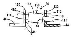
도 16 및 도 17에 나타내는 바와 같이, 실시예6에 따른 단속소자(2C)는, 지 지체로서의 기판(18)(도 5 및 도 6 참조)에, 서로 이간해서 고정된 한 쌍의 고정단자(12C 및 12D)와, 한 쌍의 고정단자(12C 및 12D)에 대하여 이동가능하고, 상기 이동에 따라 한 쌍의 고정단자(12C 및 12D)에 접촉 혹은 비접촉하고, 이것들의 고정단자(12C 및 12D)를 도통 혹은 절연시키는 가동부재(11C)를 구비하여 구성되어 있다.As shown in FIG. 16 and FIG. 17, the intermittent element 2C according to the sixth embodiment includes a pair of fixed terminals fixedly spaced apart from each other on the substrate 18 (see FIGS. 5 and 6) serving as a support member. 12C and 12D and a pair of fixed
고정단자(12C 및 12D)는 모두, 상술한 실시예에서 설명한 고정단자(12A 및 12B)와 같은 도전성 재료로 이루어지고, 기판(18)에 세워 설치되는 측벽과, 측벽(41C 및 41D)에 각각 연속해서 형성됨과 아울러, 기판(18)에 각각 고정되는 고정부(44)를 구비한, 대략 L자상을 갖추고 있다. 이 고정단자(12C 및 12D)는, 측벽(41C 및 41D)이 서로 대향하도록 설치되어 있다. 측벽(41C 및 41D)의 대략 중앙부에는, 가동부재(11C)의 직경보다 큰 직경을 구비한 관통공(10)이 각각 형성되어 있고, 이 관통공(10)에 가동부재(11C)가 헐겁게 관통되어 있다. 또한, 측벽(41C 및 41D)에는 노치(16)가 형성되어 있고, 상술한 실시예와 마찬가지로, 가동부재(11C)를 관통공(10)에 탄발적으로 삽입가능하게 되어 있다. 또한, 관통공(10)은, 관통공(10)에 헐겁게 관통된 가동부재(C)의 양단(11f)이 고정부(44)에 접촉하지 않도록 기판(18)으로부터의 높이(45)가 설정되어 있다.The fixed
가동부재(11C)는, 상술한 실시예에서 설명한 가동부재(11)와 같은 도전성 재료로 이루어지고, 대략 원기둥형상을 구비하고 있다. 이 가동부재(11C)는, 그 길이가 고정단자(12C)의 측벽(41C)과, 고정단자(12D)의 측벽(41D)까지의 거리보다 길게 구성되어 있으며, 일단(11f)이 고정단자(12C)의 관통공(10)에 헐겁게 관통되고, 타 단(11f)이 고정단자(12D)의 관통공(10)에 헐겁게 관통되어 있다. 이 가동부재(11C)의 대략 중앙부 부근(한 쌍의 고정단자(12C 및 12D)의 사이에 위치하는 부분)에는, 관통공(10)보다 지름이 큰 턱부(鍔部)(11e)가 형성되어 있다.The movable member 11C is made of the same conductive material as the
이 턱부(11e)는, 관통공(10)에 헐겁게 관통된 가동부재(11C)가, 외부로부터 부여된 진동에 따라 불규칙하게 움직이고, 관통공(10)을 획정하고 있는 가장자리부(43) 및 / 또는 측벽(41C) 및 / 또는 측벽(41D)에 접촉하거나 이탈하거나 하는 때에, 측벽(41C) 및 / 또는 측벽(41D)에 접촉해서 가동부재(11C)의 이동을 저지함으로써, 가동부재(11C)가, 관통공(10)으로부터 빠져 떨어지는 것을 방지하는 역할을 하고 있다. 또한, 턱부(11e)는, 가장자리부(43)와의 불규칙한 접촉·비접촉을 행할 수 있기 때문에, 한 쌍의 고정단자(12C 및 12D)와, 가동부재(11C)와의 도통 및 절연을, 더욱 불규칙하게 행할 수 있다.The jaw portion 11e has an
또한, 가동부재(11C)는, 상술한 가동부재(11)와 마찬가지로, 모든 방향에 대해서 이동가능하다. 따라서, 어떤 방향의 진동이 발생해도 상기 동작을 행할 수 있다.In addition, the movable member 11C is movable in all directions similarly to the
실시예6에 따른 단속소자(2C)는, 고정단자(12C 및 12D)가 대략 L자상을 가지고 있기 때문에 도 1에 나타내는 바와 같은 대략 U자상을 가지는 고정단자(12A 및 12B)에 비해, 더욱 소형화, 경량화를 달성할 수 있다.The intermittent elements 2C according to the sixth embodiment are further miniaturized compared to the fixed
[실시예7]Example 7
다음에, 본 발명의 실시예7에 따른 단속소자에 대해서 도면을 참조하여 설명한다. 또한, 실시예7에서는, 상술한 실시예에서 설명한 부재와 같은 부재에는 동일 한 부호를 붙이고, 그 상세한 설명은 생략한다.Next, an interruption device according to a seventh embodiment of the present invention will be described with reference to the drawings. In addition, in Example 7, the same code | symbol is attached | subjected to the same member as the member demonstrated in the above-mentioned Example, and the detailed description is abbreviate | omitted.
도 18은, 실시예7에 따른 단속소자의 측면도이고, 일부를 도 17에 나타내는 G - G선에 따른 단면과 같은 단면으로 나타내는 도면이다.FIG. 18 is a side view of an interruption device according to a seventh embodiment, showing a part of the same as a cross section taken along the line G-G shown in FIG.
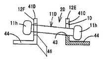
도 18에 나타내는 바와 같이, 실시예7에 따른 단속소자(2D)의, 실시예6에 따른 단속소자(2C)와 다른 주된 점은, 가동부재(11D)의 구성과, 고정단자(12E 및 12F)에 형성된 관통공(10)의 기판(18)으로부터의 높이(46)이다.As shown in FIG. 18, the main points of the
도 18에 나타내는 바와 같이, 실시예7에 따른 단속소자(2D)의 가동부재(11D)는, 고정단자(12E)에 형성된 관통공(10)과, 고정단자(12F)에 형성된 관통공(10)을 각각 관통한 양단에 관통공(10)보다 지름이 큰 턱부(11h)가 각각 형성되어 있다.As shown in Fig. 18, the
양 턱부(11h)는, 관통공(10)에 헐겁게 관통된 가동부재(11D)가 외부로부터 부여된 진동에 따라 불규칙하게 움직이고, 관통공(10)을 획정하고 있는 가장자리부(43) 및 / 또는 측벽(41C) 및 / 또는 측벽(41D)에 접촉하거나 떨어지거나 할 때에, 측벽(41C) 및 / 또는 측벽(41D)에 접촉해서 가동부재(11C)의 이동을 저지함으로써, 가동부재(11C)가 관통공(10)으로부터 빠져 떨어지는 것을 방지하는 역할을 부여하고 있다. 또한, 턱부(11h)는, 가장자리부(43)와의 불규칙한 접촉·비접촉을 행할 수 있기 때문에, 한 쌍의 고정단자(12E 및 12F)와, 가동부재(11D)와의 도통 및 절연을 또한 불규칙하게 행할 수 있다.Both
고정단자(12E 및 12F)는, 관통공(10)에 헐겁게 관통된 가동부재(11D)의 양단에 형성된 턱부(11h)의 각각이 고정부(44)에 접촉하지 않도록, 기판(18)으로부터의 높이(46)가 설정되어 있다.The fixed
또한, 가동부재(11D)도, 상술한 가동부재(11)와 마찬가지로 모든 방향에 대해서 이동가능하다. 따라서, 어떤 방향의 진동이 발생해도 상기 동작을 행할 수 있다.The
[실시예8]Example 8
다음에, 본 발명의 실시예8에 따른 고전위 불규칙 펄스전류 발생회로를, 이온 칫솔에 사용했을 경우에 대해서 도면을 참조하여 설명한다. 또한, 실시예8에서는, 상술한 실시예에서 설명한 부재와 같은 부재에는 동일한 부호를 붙이고, 그 상세한 설명은 생략한다.Next, a case where a high potential irregular pulse current generation circuit according to Embodiment 8 of the present invention is used for an ion toothbrush will be described with reference to the drawings. In addition, in Example 8, the same code | symbol is attached | subjected to the same member as the member demonstrated in the above-mentioned Example, and the detailed description is abbreviate | omitted.
도 19는, 실시예8에 따른 고전위 불규칙 펄스전류 발생회로를 이온 칫솔에 사용했을 경우를 나타내는 도면이다.Fig. 19 is a diagram showing a case where a high potential irregular pulse current generation circuit according to the eighth embodiment is used for an ion toothbrush.
도 19에 나타내는 고전위 불규칙 펄스전류 발생회로는, 발진·승압 트랜스(94)의 일차측에는 전원(20)과, 증폭소자(6)와, 한류용(限流用)의 저항기(96)와, 스위치(97)가 접속되어 있다. 한편, 발진·승압 트랜스(94)의 2차측(출력측)에는, 단속소자(2)와, 고지소자로서의 발광소자(5)가 병렬로 접속되어 있다. 이 발광소자(5)에는, 발광소자(5)가 적절히 동작되기 위해 필요한 전류량으로 하기 위한 저항기(98)가 직렬로 접속되어 있다. 또한, 부호 93은 정류기이다.In the high potential irregular pulse current generating circuit shown in Fig. 19, the
고전위 불규칙 펄스전류 발생회로의 한 쪽의 출력단자는, 이온 칫솔(90A)의 도전성 부재(91A)에 접속되어 있고, 따라서, 브러시모(61)가 상술한 접촉전극(3)의 한 쪽의 단자가 된다. 또한, 고전위 불규칙 펄스전류 발생회로의 다른 쪽의 출력단자는, 도전판(92A)에 접속되어 있고, 이 도전판(92A)이 상술한 접촉전극(3)의 다른 쪽의 단자가 된다. 또한, 이 이온 칫솔(90A)에는, 고전위 불규칙 펄스전류 발생회로가 접속되어 있기 때문에, 이 이온 칫솔(90A)은 고전위 칫솔이 된다.One output terminal of the high potential irregular pulse current generation circuit is connected to the
이 이온 칫솔(90A)은, 실시예1과 마찬가지로, 단속소자(2)가 온 상태가 되었을 때 발광소자(5)는 작동하지 않고, 단속소자(2)측에만 높은 전압(예를 들면, 200V정도)의 펄스전류가 흐르며, 브러시모(61)로부터 구중에 공급된다. 한편, 단속소자(2)가 오프 상태가 되었을 때, 발광소자(5)가 작동해서 전압이 하강한 상태로 낮은 전압의 펄스전류가 흘러 브러시(61)로부터 구중에 공급된다.Similarly to the first embodiment, the
또한, 고전위 불규칙 펄스전류 발생회로는, 도 20에 나타내는 바와 같이, 이온 칫솔(90A) 대신에 맛사지기(90B)에 사용할 수도 있다. 또한, 부호 99는, 맛사지기(90B)에 맛사지를 위한 진동을 부여하는 모터이고, 단속소자(2)는, 이 모터(99)의 진동에 의해 불규칙하게 온 상태 혹은 오프 상태가 된다.In addition, the high potential irregular pulse current generating circuit can be used for the massaging
맛사지기(90B)는, 그 선단(사용자가 맛사지하기 위해 피부에 접촉하는 부위)이 도전성 부재(91)로 형성되어 있다. 또한, 맛사지기(90B)의 사용자가 파지하는 부분에는, 도전판(92)이 바깥 둘레를 따라 설치되어 있다. 그리고, 고전위 불규칙 펄스전류 발생회로의 한 쪽의 출력단자는, 도전성 부재(91)에 접속되어 있고, 따라서, 도전성 부재(91)가 상술한 접촉전극(3)의 한 쪽 단자가 된다. 또한, 고전위 불규칙 펄스전류 발생회로의 다른 쪽의 출력단자는 도전판(92)에 접속되어 있고, 이 도전판(92)이 상술한 접촉전극(3)의 다른 쪽의 단자가 된다.In the massaging
또한, 실시예8에서는, 고전위 불규칙 펄스전류 발생회로에 단속소자(2)를 사용했을 경우에 대해서 설명했지만, 이것에 한정하지 않고, 단속소자(2C, 2D 및 50) 를 사용해도 좋다.In addition, in Example 8, although the case where the
이상과 같이 본 발명에 의하면, 소형화가 가능하고, 구조가 단순하며, 소비전력이 작고, 저비용이며, 회로를 불규칙하게 도통 및 절연시킴으로써, 불규칙한 펄스전류를 발생시키는 것이 가능한 단속소자, 이 단속소자를 구비한 회로, 고전위 불규칙 펄스전류 발생회로, 및 이 회로를 구비한 회로기판, 및 이 회로를 구비한 펄스전류 발생장치, 및 고전위 불규칙 펄스전류 발생장치, 및 단속소자의 조립방법을 제공할 수 있다.As described above, according to the present invention, an interruption element capable of miniaturization, simple structure, low power consumption, low cost, and irregular circuit current can be generated by irregularly conducting and insulating circuits, To provide a circuit, a high potential irregular pulse current generation circuit, and a circuit board including the circuit, a pulse current generator including the circuit, and a high potential irregular pulse current generator, and an intermittent element. Can be.
Claims (44)
Translated fromKoreanApplications Claiming Priority (4)
| Application Number | Priority Date | Filing Date | Title |
|---|---|---|---|
| JP2004158562 | 2004-05-28 | ||
| JPJP-P-2004-00158562 | 2004-05-28 | ||
| JPJP-P-2005-00086770 | 2005-03-24 | ||
| JP2005086770AJP4255452B2 (en) | 2004-05-28 | 2005-03-24 | Ion toothbrush |
Publications (2)
| Publication Number | Publication Date |
|---|---|
| KR20060046219A KR20060046219A (en) | 2006-05-17 |
| KR100880559B1true KR100880559B1 (en) | 2009-01-30 |
Family
ID=34941477
Family Applications (1)
| Application Number | Title | Priority Date | Filing Date |
|---|---|---|---|
| KR1020050045017AExpired - Fee RelatedKR100880559B1 (en) | 2004-05-28 | 2005-05-27 | Intermittent elements, circuits and devices provided with them, and methods of assembling intermittent elements |
Country Status (4)
| Country | Link |
|---|---|
| US (1) | US7566839B2 (en) |
| EP (1) | EP1600991A1 (en) |
| JP (1) | JP4255452B2 (en) |
| KR (1) | KR100880559B1 (en) |
Families Citing this family (33)
| Publication number | Priority date | Publication date | Assignee | Title |
|---|---|---|---|---|
| JP4306681B2 (en)* | 2003-06-20 | 2009-08-05 | サンスター株式会社 | electric toothbrush |
| US7767919B2 (en)* | 2006-02-08 | 2010-08-03 | Pcb Piezotronics Inc. | Sealed control device with magnetically adjustable control parameter |
| JP4218721B2 (en)* | 2006-10-06 | 2009-02-04 | パナソニック電工株式会社 | Oral hygiene equipment |
| RU2371142C2 (en)* | 2006-12-22 | 2009-10-27 | Панасоник Электрик Воркс Ко., Лтд. | Electric drive and tooth brush wherein it is used |
| EP2273901A2 (en)* | 2008-04-08 | 2011-01-19 | L'Oréal | Vibrating applicator |
| ES2610755T3 (en) | 2012-08-27 | 2017-05-03 | Aktiebolaget Electrolux | Robot positioning system |
| KR102137923B1 (en) | 2013-04-15 | 2020-07-24 | 에이비 엘렉트로룩스 | Robotic vacuum cleaner with protruding sidebrush |
| WO2014169943A1 (en) | 2013-04-15 | 2014-10-23 | Aktiebolaget Electrolux | Robotic vacuum cleaner |
| US10209080B2 (en) | 2013-12-19 | 2019-02-19 | Aktiebolaget Electrolux | Robotic cleaning device |
| WO2015090405A1 (en) | 2013-12-19 | 2015-06-25 | Aktiebolaget Electrolux | Sensing climb of obstacle of a robotic cleaning device |
| CN105793790B (en) | 2013-12-19 | 2022-03-04 | 伊莱克斯公司 | Prioritize cleaning areas |
| KR102116596B1 (en) | 2013-12-19 | 2020-05-28 | 에이비 엘렉트로룩스 | Robotic vacuum cleaner with side brush moving in spiral pattern |
| US10617271B2 (en) | 2013-12-19 | 2020-04-14 | Aktiebolaget Electrolux | Robotic cleaning device and method for landmark recognition |
| US10433697B2 (en) | 2013-12-19 | 2019-10-08 | Aktiebolaget Electrolux | Adaptive speed control of rotating side brush |
| CN105829985B (en) | 2013-12-19 | 2020-04-07 | 伊莱克斯公司 | Robot cleaning device with peripheral recording function |
| WO2015090439A1 (en) | 2013-12-20 | 2015-06-25 | Aktiebolaget Electrolux | Dust container |
| CN106415423B (en) | 2014-07-10 | 2021-01-01 | 伊莱克斯公司 | Method for detecting a measurement error of a robotic cleaning device |
| US10499778B2 (en) | 2014-09-08 | 2019-12-10 | Aktiebolaget Electrolux | Robotic vacuum cleaner |
| EP3190938A1 (en) | 2014-09-08 | 2017-07-19 | Aktiebolaget Electrolux | Robotic vacuum cleaner |
| US20160093451A1 (en)* | 2014-09-26 | 2016-03-31 | Mechanical Products Company | Lighted circuit breaker status indication device |
| EP3230814B1 (en) | 2014-12-10 | 2021-02-17 | Aktiebolaget Electrolux | Using laser sensor for floor type detection |
| CN107072454A (en) | 2014-12-12 | 2017-08-18 | 伊莱克斯公司 | Side brushes and robot vacuums |
| CN107003669B (en) | 2014-12-16 | 2023-01-31 | 伊莱克斯公司 | Experience-Based Roadmap for Robotic Cleaning Equipment |
| EP3234713B1 (en) | 2014-12-16 | 2022-06-15 | Aktiebolaget Electrolux | Cleaning method for a robotic cleaning device |
| US11099554B2 (en) | 2015-04-17 | 2021-08-24 | Aktiebolaget Electrolux | Robotic cleaning device and a method of controlling the robotic cleaning device |
| EP3344104B1 (en) | 2015-09-03 | 2020-12-30 | Aktiebolaget Electrolux | System of robotic cleaning devices |
| WO2017102897A1 (en)* | 2015-12-18 | 2017-06-22 | Koninklijke Philips N.V. | Brush with sponge or foam element |
| WO2017157421A1 (en) | 2016-03-15 | 2017-09-21 | Aktiebolaget Electrolux | Robotic cleaning device and a method at the robotic cleaning device of performing cliff detection |
| US11122953B2 (en) | 2016-05-11 | 2021-09-21 | Aktiebolaget Electrolux | Robotic cleaning device |
| EP3629869B1 (en) | 2017-06-02 | 2023-08-16 | Aktiebolaget Electrolux | Method of detecting a difference in level of a surface in front of a robotic cleaning device |
| EP3687357B1 (en) | 2017-09-26 | 2024-07-10 | Aktiebolaget Electrolux | Controlling movement of a robotic cleaning device |
| WO2019155631A1 (en)* | 2018-02-09 | 2019-08-15 | 正弘 内池 | Cosmetic apparatus |
| BG112714A (en)* | 2018-04-02 | 2019-10-31 | Стоян ГВОЗДЕЙКОВ | Collapsible ion hygiene brush and oral cavity treatment procedures |
Citations (2)
| Publication number | Priority date | Publication date | Assignee | Title |
|---|---|---|---|---|
| JPH09108453A (en)* | 1995-10-19 | 1997-04-28 | Sente Creations:Kk | Switch for toys and toys using the same |
| JPH1173831A (en) | 1997-08-29 | 1999-03-16 | Seiko Epson Corp | Switch device and electronic device equipped with switch device |
Family Cites Families (26)
| Publication number | Priority date | Publication date | Assignee | Title |
|---|---|---|---|---|
| JPS5313205B2 (en) | 1973-06-05 | 1978-05-09 | ||
| IE45963B1 (en)* | 1977-06-27 | 1983-01-12 | Anderson F | A vibration sensing device |
| JPS55116525U (en) | 1979-02-08 | 1980-08-16 | ||
| JPS5734846A (en)* | 1980-08-06 | 1982-02-25 | Funaki Electronik Works | Electric mouth washing nozzle |
| DE3211984C2 (en)* | 1981-05-21 | 1986-04-03 | Dieter Dr. 7900 Ulm Benz | Rotating toothbrush |
| JPS5910466A (en) | 1982-07-12 | 1984-01-19 | Toshiba Mach Co Ltd | Charging ladle |
| US4665921A (en)* | 1984-05-28 | 1987-05-19 | Teranishi Electric Works, Ltd. | High potential generating toothbrush |
| JPS60253461A (en) | 1984-05-28 | 1985-12-14 | 株式会社 寺西電機製作所 | High potential toothbrush |
| US4709438A (en)* | 1986-03-31 | 1987-12-01 | Tavares Joaquim De | Toothbrush with gravity switch |
| DE3715497A1 (en)* | 1987-05-09 | 1988-11-17 | Braun Ag | SAFETY SWITCHING DEVICE FOR CONTROLLING A POWER CONSUMER |
| JPH0249734A (en) | 1988-08-12 | 1990-02-20 | Wakunaga Pharmaceut Co Ltd | Novel composition |
| JPH06290690A (en) | 1993-03-30 | 1994-10-18 | Heiwa Tokei Seisakusho:Kk | Spherical contact switch |
| JP2891120B2 (en) | 1994-11-07 | 1999-05-17 | セイコーエプソン株式会社 | Small reducer |
| JPH08162798A (en) | 1994-12-02 | 1996-06-21 | Matsushita Electric Ind Co Ltd | Electronic component, its mounting method, and mounting apparatus |
| US5550721A (en)* | 1995-05-08 | 1996-08-27 | Carmen & Thomas Rapisarda Enterprises | Motion sensitive light and battery assembly switched on and off by the oscillation of a helical spring |
| US5599088A (en)* | 1995-08-21 | 1997-02-04 | Chien; Tseng L. | Flashing footwear light module |
| DE69934771T2 (en) | 1998-05-29 | 2007-10-18 | Hukuba Dental K.K., Nagareyama | TOOTHBRUSH |
| JP2000331579A (en) | 1999-05-21 | 2000-11-30 | Koshin:Kk | Inclination and vibration sensor and its board mounting |
| US6397424B1 (en)* | 1999-12-10 | 2002-06-04 | Kwok Wai Leung | Toothbrush |
| US6334692B1 (en)* | 2000-09-25 | 2002-01-01 | Yeong-Shyan Hsueh | Decorative member having vibration actuating light |
| JP3527473B2 (en) | 2000-11-27 | 2004-05-17 | 株式会社ジェッター | Falling object detector |
| JP2004146302A (en) | 2002-10-28 | 2004-05-20 | Sony Corp | Switch, operating button, input device, key input device, electronic apparatus, and apparatus |
| US7329019B2 (en)* | 2002-12-17 | 2008-02-12 | James Cheung | Clothing or footwear illumination system having electro-luminescent and LED light sources |
| US7170019B2 (en)* | 2003-07-14 | 2007-01-30 | Cheerine Development (Hong Kong), Ltd. | Inertia switch and flashing light system |
| US6949713B2 (en)* | 2004-01-22 | 2005-09-27 | Ming-Bi Weng | Lighting system having vibration switch and with plurality of displaying sequences |
| US7182493B2 (en)* | 2005-06-30 | 2007-02-27 | Teng-Wen Huang | Automatic dual-control light emitting assembly for vehicle wheels |
- 2005
- 2005-03-24JPJP2005086770Apatent/JP4255452B2/ennot_activeExpired - Fee Related
- 2005-05-27EPEP05253265Apatent/EP1600991A1/ennot_activeWithdrawn
- 2005-05-27KRKR1020050045017Apatent/KR100880559B1/ennot_activeExpired - Fee Related
- 2005-05-27USUS11/139,023patent/US7566839B2/ennot_activeExpired - Fee Related
Patent Citations (2)
| Publication number | Priority date | Publication date | Assignee | Title |
|---|---|---|---|---|
| JPH09108453A (en)* | 1995-10-19 | 1997-04-28 | Sente Creations:Kk | Switch for toys and toys using the same |
| JPH1173831A (en) | 1997-08-29 | 1999-03-16 | Seiko Epson Corp | Switch device and electronic device equipped with switch device |
Also Published As
| Publication number | Publication date |
|---|---|
| JP4255452B2 (en) | 2009-04-15 |
| EP1600991A1 (en) | 2005-11-30 |
| US7566839B2 (en) | 2009-07-28 |
| JP2006012777A (en) | 2006-01-12 |
| US20060028306A1 (en) | 2006-02-09 |
| KR20060046219A (en) | 2006-05-17 |
| HK1079897A1 (en) | 2006-04-13 |
Similar Documents
| Publication | Publication Date | Title |
|---|---|---|
| KR100880559B1 (en) | Intermittent elements, circuits and devices provided with them, and methods of assembling intermittent elements | |
| JP3967549B2 (en) | toothbrush | |
| KR101633564B1 (en) | Oral care devices having automatic mode selection | |
| KR102622443B1 (en) | Electric toothbrush | |
| JP3229284U (en) | Pins and brushes for skin irritation brushes | |
| US20190380482A1 (en) | Oral care device and attachment | |
| ATE502597T1 (en) | MOUTH CLEANING DEVICE | |
| KR20230127570A (en) | Skin massage device | |
| HK1079897B (en) | Contact-breaker device, circuit and apparatus comprising the same, and method for assembling contact-breaker device | |
| JP4134022B2 (en) | Electrical stimulator | |
| JP2002325634A (en) | Handle for supplying electric current having pulse ion effect to human body surface of inner mouse | |
| JP2023033174A (en) | Facial instrument | |
| JP2006223365A (en) | Electrode unit and bath energization device | |
| UA59029A (en) | Interdental stimulator |
Legal Events
| Date | Code | Title | Description |
|---|---|---|---|
| PA0109 | Patent application | St.27 status event code:A-0-1-A10-A12-nap-PA0109 | |
| PG1501 | Laying open of application | St.27 status event code:A-1-1-Q10-Q12-nap-PG1501 | |
| A201 | Request for examination | ||
| P11-X000 | Amendment of application requested | St.27 status event code:A-2-2-P10-P11-nap-X000 | |
| P13-X000 | Application amended | St.27 status event code:A-2-2-P10-P13-nap-X000 | |
| PA0201 | Request for examination | St.27 status event code:A-1-2-D10-D11-exm-PA0201 | |
| E902 | Notification of reason for refusal | ||
| PE0902 | Notice of grounds for rejection | St.27 status event code:A-1-2-D10-D21-exm-PE0902 | |
| E13-X000 | Pre-grant limitation requested | St.27 status event code:A-2-3-E10-E13-lim-X000 | |
| P11-X000 | Amendment of application requested | St.27 status event code:A-2-2-P10-P11-nap-X000 | |
| P13-X000 | Application amended | St.27 status event code:A-2-2-P10-P13-nap-X000 | |
| E701 | Decision to grant or registration of patent right | ||
| PE0701 | Decision of registration | St.27 status event code:A-1-2-D10-D22-exm-PE0701 | |
| GRNT | Written decision to grant | ||
| PR0701 | Registration of establishment | St.27 status event code:A-2-4-F10-F11-exm-PR0701 | |
| PR1002 | Payment of registration fee | St.27 status event code:A-2-2-U10-U11-oth-PR1002 Fee payment year number:1 | |
| PG1601 | Publication of registration | St.27 status event code:A-4-4-Q10-Q13-nap-PG1601 | |
| PR1001 | Payment of annual fee | St.27 status event code:A-4-4-U10-U11-oth-PR1001 Fee payment year number:4 | |
| FPAY | Annual fee payment | Payment date:20130114 Year of fee payment:5 | |
| PR1001 | Payment of annual fee | St.27 status event code:A-4-4-U10-U11-oth-PR1001 Fee payment year number:5 | |
| FPAY | Annual fee payment | Payment date:20140110 Year of fee payment:6 | |
| PR1001 | Payment of annual fee | St.27 status event code:A-4-4-U10-U11-oth-PR1001 Fee payment year number:6 | |
| LAPS | Lapse due to unpaid annual fee | ||
| PC1903 | Unpaid annual fee | St.27 status event code:A-4-4-U10-U13-oth-PC1903 Not in force date:20150121 Payment event data comment text:Termination Category : DEFAULT_OF_REGISTRATION_FEE | |
| PC1903 | Unpaid annual fee | St.27 status event code:N-4-6-H10-H13-oth-PC1903 Ip right cessation event data comment text:Termination Category : DEFAULT_OF_REGISTRATION_FEE Not in force date:20150121 |