KR100880290B1 - Method and apparatus for displacing moving plate of hexapod turret - Google Patents
Method and apparatus for displacing moving plate of hexapod turretDownload PDFInfo
- Publication number
- KR100880290B1 KR100880290B1KR1020037001452AKR20037001452AKR100880290B1KR 100880290 B1KR100880290 B1KR 100880290B1KR 1020037001452 AKR1020037001452 AKR 1020037001452AKR 20037001452 AKR20037001452 AKR 20037001452AKR 100880290 B1KR100880290 B1KR 100880290B1
- Authority
- KR
- South Korea
- Prior art keywords
- moving plate
- hexapod
- displacing
- plate
- rotation
- Prior art date
- Legal status (The legal status is an assumption and is not a legal conclusion. Google has not performed a legal analysis and makes no representation as to the accuracy of the status listed.)
- Expired - Fee Related
Links
Images


Classifications
- H—ELECTRICITY
- H01—ELECTRIC ELEMENTS
- H01Q—ANTENNAS, i.e. RADIO AERIALS
- H01Q1/00—Details of, or arrangements associated with, antennas
- H01Q1/12—Supports; Mounting means
- H—ELECTRICITY
- H01—ELECTRIC ELEMENTS
- H01Q—ANTENNAS, i.e. RADIO AERIALS
- H01Q1/00—Details of, or arrangements associated with, antennas
- H01Q1/12—Supports; Mounting means
- H01Q1/125—Means for positioning
- H—ELECTRICITY
- H01—ELECTRIC ELEMENTS
- H01Q—ANTENNAS, i.e. RADIO AERIALS
- H01Q3/00—Arrangements for changing or varying the orientation or the shape of the directional pattern of the waves radiated from an antenna or antenna system
- H01Q3/02—Arrangements for changing or varying the orientation or the shape of the directional pattern of the waves radiated from an antenna or antenna system using mechanical movement of antenna or antenna system as a whole
- H01Q3/08—Arrangements for changing or varying the orientation or the shape of the directional pattern of the waves radiated from an antenna or antenna system using mechanical movement of antenna or antenna system as a whole for varying two co-ordinates of the orientation
- Y—GENERAL TAGGING OF NEW TECHNOLOGICAL DEVELOPMENTS; GENERAL TAGGING OF CROSS-SECTIONAL TECHNOLOGIES SPANNING OVER SEVERAL SECTIONS OF THE IPC; TECHNICAL SUBJECTS COVERED BY FORMER USPC CROSS-REFERENCE ART COLLECTIONS [XRACs] AND DIGESTS
- Y10—TECHNICAL SUBJECTS COVERED BY FORMER USPC
- Y10T—TECHNICAL SUBJECTS COVERED BY FORMER US CLASSIFICATION
- Y10T74/00—Machine element or mechanism
- Y10T74/20—Control lever and linkage systems
- Y10T74/20207—Multiple controlling elements for single controlled element
- Y10T74/20305—Robotic arm
- Y10T74/20329—Joint between elements
Landscapes
- Control Of Position Or Direction (AREA)
- Manipulator (AREA)
- Shaping Of Tube Ends By Bending Or Straightening (AREA)
- Variable-Direction Aerials And Aerial Arrays (AREA)
Abstract
Translated fromKoreanDescription
Translated fromKorean본 발명은 안테나, 옵트로닉 장치(optronic apparatus) 또는 망원경, 광학 측정장비 또는 통신 장비 또는 공간에 방향성을 요하는 기능을 갖는 어떠한 장치 등의 플롯팅 장비(plotting equipment)에 대한 헥사포드 터렛의 적용에 관한 것이다.The present invention is directed to the application of hexapod turrets to plotting equipment, such as antennas, optronic devices or telescopes, optical measuring equipment or communication equipment, or any device having a function that requires directionality in space. It is about.
헥사포드 터렛 또는 스튜워트(stewart) 또는 고프(gough) 플랫폼(platform)은 안테나 또는 망원경에 대한 지지체로서 일반적으로 그 방향을 조절할 수 있도록 사용되는 장치이다. 앤트 나흐리히텐테크(ANT NACHRICHTENTECH)에 의해 1992년 5월 12일자로 출원된 유럽특허 EP 0 515 888호는 헥사포드 터렛을 구비하는 플롯팅 장치의 예에 대해 기술한다. 헥사포드 터렛은 플랫폼 또는 고정 베이스, 방향성을 갖도록 장치에 고정되는 이동판, 및 베이스와 이동판을 결합하는 조정 가능한 6개의 레그(leg)를 구비한다. 카르단 형식 링크(cardan type link)에 의해 레그가 삼각형으로 형성되도록 레그의 단부에 이동판 및 베이스가 쌍으로 고정된다. 각각의 레그는 서로에 대해 슬라이딩(sliding) 가능한 2개의 네스티드 튜브(nested tube)를 구비한다. 이들 튜브는 레그의 길이를 조절할 수 있는 직선형 압전 모터(linear piezo-electric motor)에 의해 구동된다. 이 장치는 6개의 자유도(degree of liberty)에 의해 이동판이 이동되는 것을 가능하게 한다.A hexaford turret or stewart or gough platform is a device generally used to adjust its orientation as a support for an antenna or telescope.
유럽특허 EP 0 515 888호에서, 헥사포드 터렛은 인공위성(satellite)에 장착되며, 그 역활은 본래, 선명한 시계(clear view)를 얻고, 그 것의 방향성을 갖지만 작은 틈을 갖는 대량의 인공위성 장치를 "출현시키는것(bring out)"이다.In EP 0 515 888, the hexapod turret is mounted on a satellite, the role of which is essentially to obtain a large view of the satellite device having its clear view and having its direction but with a small gap. "Bring out".
본 발명의 목적은 지평선(horizon) 위에 적어도 반-공간(demi-space)을 덮도록 적어도 2π스테라디안(steradian)의 시계 및 상당한 간극에 의해 장비를 배향시키는 헥사포드 장치를 사용하는 것이다.It is an object of the present invention to use a hexapod device that orients the equipment by a clock and a significant gap of at least 2π steradian to cover at least demi-space above the horizon.
헥사포드 구조를 사용함으로써 나타나는 문제는 동일 관절(articulation)의 2개의 레그와 고정 베이스 또는 이동판의 평면에 수직한 사이의 각이 90°에 접근할 때, 그 강성을 잃게 되는 것이며, 이 현상은 "토글 조인트(toggle joint)" 효과로서 널리 공지되어 있다.The problem with using hexapod structures is that when the angle between two legs of the same articulation and perpendicular to the plane of the fixed base or moving plate approaches 90 °, its stiffness is lost. It is well known as the "toggle joint" effect.
본 발명의 다른 목적은 처음부터 끝까지 양호한 강성을 유지하며 반-공간의 모든 방향으로 장치를 배향시킬 수 있는 것이다.Another object of the present invention is to be able to orient the device in all directions of the semi-space while maintaining good stiffness from beginning to end.
이 때문에, 본 발명은 방위 상하각(αi, βi) 좌표(azimuth-elevation coordinate)에 의해 정의된 방향(V1)으로부터 그 것의 방위 상하각(αi+1, βi+1) 좌표에 의해 정의된 방향(Vi+1)을 향해, 길이 조절 장치가 설치된 레그를 갖는 헥사포드의 이동판을 변위시키는 방법에 있어서,Therefore, the present invention bearing the vertical angle (αi, βi) coordinates (azimuth-elevation coordinate) in the direction (V1) of those things azimuth elevation angle(α i + 1, β i + 1) from the as defined by the coordinates In a method for displacing a moving plate of a hexapod having a leg provided with a length adjusting device toward the direction (Vi + 1 ) defined by
-판의 방향에 따라 오프셋 거리(d)를 정의하는 규칙을 정의하는 단계,Defining a rule defining an offset distance d according to the direction of the plate,
-방향(Vi+1)에 상응하는 오프셋 거리를 판정하는 단계, 및Determining an offset distance corresponding to the direction Vi + 1 , and
-방향(Vi)으로부터 방향(Vi+1)으로 이동판을 변위시키고, 거리(d)의 Vi+1의 αi+1의 방위면에 상기 베이스의 중심(OA)을 통해 헥사포드의 고정 베이스에 수직하게 그것을 오프셋시키기 위해 레그의 길이(L1 내지 L6)를 변경시키도록 조절 장치를 제어하는 단계를 구비하는 것을 특징으로 하는 헥사포드의 이동판을 변위시키는 방법을 제안한다.Displaces the moving plate from the direction (Vi ) to the direction (Vi + 1 ) and through the center OA of the base to the azimuth plane of αi + 1 of Vi + 1 of distance d And controlling the adjusting device to change the lengths (L1 to L6 ) of the legs to offset it perpendicular to the fixed base of the method.
바람직하게, 이 방법은 특이점(singular point), 즉 헥사포트 터렛이 그 강성을 잃게 되는 위치를 효과적으로 회피하도록 오프셋에 헥사포드의 판이 위치되는 것을 허용한다.Preferably, this method allows the hexapod's plate to be positioned at an offset to effectively avoid the singular point, ie where the hexaport turret loses its stiffness.
더욱 바람직하게는, 오프셋 규칙은 그 방향의 함수로서 공간에 판의 중심(OB)의 유일 위치를 부여하도록 정의된다. 이 규칙은 판의 중심(OB)을 산출하는 "오프셋 표면"으로 공지된 기하학상의 면을 정의한다.More preferably, the offset rule is defined to give the space a unique position of the center OB of the plate as a function of its direction. This rule defines a geometric face known as an "offset surface" that yields the center (OB) of the plate.
본 방법의 변형에 따라,According to a variant of the method,
-오프셋 규칙은 연속기하학 면을 정의하고,The offset rule defines the continuity geometry plane,
-오프셋 면은 평면이며,The offset face is flat,
-오프셋 면은 구의 일부분이다.The offset face is part of the sphere.
이동판은 지시 벡터(pointing vector)(Vi및 Vi+1)를 포함하는 평면에 수직한 축에 따라 이동판의 회전을 제어함으로써 변위될 수 있다.The moving plate can be displaced by controlling the rotation of the moving plate along an axis perpendicular to the plane containing the pointing vectors Vi and Vi + 1 .
헥사포드의 레그의 길이의 변형은 하기 단계,The modification of the length of the legs of the hexapod is carried out in the following steps,
-모든 레그가 동일 길이(L0)로 조절됨에 따라 헥사포드의 기준 위치(reference position)가 정의되는 단계,The reference position of the hexapod is defined as all legs are adjusted to the same length (L0 ),
-오프셋 규칙에 의해 정의된 오프셋 표면을 향해 방위면(αi+1)의 가상 회전 및 판의 중심(OB)의 가상 평행 이동에 의해 기준 위치로부터 지시 방향(Vi+1)으로 헥사포드의 이동판을 이동시키도록 각각의 레그의 길이의 변형을 설정하는 단계, 및Of the hexapod from the reference position (Vi + 1 ) by the virtual rotation of the azimuth plane (αi + 1 ) and the virtual parallel movement of the center of the plate (OB) towards the offset surface defined by the offset rule. Setting a deformation of the length of each leg to move the moving plate, and
-방향(Vi)으로부터 방향(Vi+1)으로 변환하기 위해 각각의 레그로부터 총 길이의 변화량이 추론되는 단계에 따라 설정된다.The amount of change in total length from each leg is set in accordance with the step of deriving from the directionVi to the direction Vii + 1 .
레그의 길이의 변화량의 이 제어 방법은 헥사포드 터렛의 구조가 충돌에 의해 그 강성이 감소되고, 레그의 기계장치가 파손될 위험을 회피한다.This control method of the amount of change in the length of the leg avoids the risk that the structure of the hexapod turret is reduced in stiffness by collision, and the mechanism of the leg is broken.
본 발명의 실시예에서, 이동판의 총 방향 이동량은 이동판의 방위각(Δα) 및 상하각(Δβ)의 단위 변위량(unit displacement)의 연속으로 분해된다. 각각의 단위 변위량을 위해, 총 변위량 과정(가상의 평행 이동에 의해 뒤따르는 가상의 회전의 결정)이 재현된다.In the embodiment of the present invention, the total amount of movement of the moving plate is decomposed into a series of unit displacements of the azimuth angle Δα and the vertical angle Δβ of the moving plate. For each unit displacement amount, the total displacement amount process (determination of the imaginary rotation followed by the virtual parallel movement) is reproduced.
단위 변위량(Δα및 Δβ)에서의 이 분해는 하나의 위치로부터 다른 위치로 그것의 통과중에 특이점(singular point)을 통해 판이 통과하는 것을 방지한다. 이런 식으로, 이동판의 이동 중, 헥사포드 터렛이 항상 안정적인 구조인 것이 보장된다.This decomposition at unit displacement amounts Δα and Δβ prevents the plate from passing through a singular point during its passage from one position to another. In this way, during the movement of the moving plate it is ensured that the hexapod turret is always a stable structure.
이 방법은 하기의 단계,This method involves the following steps,
-조절 장치는 획득되는 레그(1, 2, 3, 4, 5, 6)의 길이(Li)의 함수로서 제어되며, 이 연산은 판(20)과 고정 베이스(10)에 레그(1, 2, 3, 4, 5, 6)를 결합시키는 링크를 만드는 구성 요소들 사이의 상대각(relative angle)을 고려하는 단계,The regulating device is controlled as a function of the length Li of the
-레그의 축에 의해 형성되며, 고정 베이스의 평면에 수직하게 형성된 각, 및 레그에 의해 형성되며, 이동판의 평면에 수직하게 형성된 각은 항상 40°와 80°사이로 정의된 최대각 보다 작게 되는 단계에 의해 바람직하게 완성된다.An angle formed by the axis of the leg, formed perpendicular to the plane of the stationary base, and formed by the leg, and formed perpendicular to the plane of the moving plate, which is always smaller than the maximum angle defined between 40 ° and 80 °. The step is preferably completed.
본 발명은 또한, 헥사포드의 각각의 레그는 서로에 대해 슬라이딩하는 제1 및 제2 조립체로 구성된 잭, 및 모터의 축에 평행 또는 수직하게 배치된 스크류의 회전을 구동시키는 출구 축을 갖는 액츄에이터를 구비하며, 상기 스크류는 제2 조립체와 함께 솔리드에 장착된 너트 내부로 선회가능하게 제1 조립체의 길이에 걸쳐 연장하며, 너트 내의 스크류의 회전은 제1 조립체에 대해 제2 조립체의 평행 이동을 야기시키는 것을 특징으로 하는 헥사포드의 이동판을 변위시키는 장치를 제안한다.The invention also has an actuator having a leg consisting of first and second assemblies each leg of the hexapod sliding relative to each other, and an outlet shaft for driving rotation of the screw disposed parallel or perpendicular to the axis of the motor. The screw pivotally extends over the length of the first assembly into a solid mounted nut with the second assembly, wherein rotation of the screw in the nut causes parallel movement of the second assembly relative to the first assembly. We propose an apparatus for displacing a moving plate of hexapod, which is characterized by the above-mentioned.
이 장치는 하기의 특징:This device has the following features:
-액츄에이터의 축의 위치를 측정하는 수단을 구비하며,Means for measuring the position of the axis of the actuator,
-반경(RA)의 제1 원을 따라 고정 베이스 상에 링크가 정렬되며, 반경(RB)의 제2 원을 따라 이동판 상에 링크가 정렬되며, RA/RB의 비는 대략 1.5이며,The link is aligned on the stationary base along the first circle of radius RA, the link is aligned on the moving plate along the second circle of radius RB, and the ratio of RA / RB is approximately 1.5,
-반경(R)의 원을 따라 이동판 또는 고정 베이스 쌍으로 링크가 정렬되며, 동일한 쌍의 2개의 링크 사이의 거리는 대략 R/10이며,The links are arranged in a moving plate or fixed base pair along a circle of radius R, the distance between two links of the same pair is approximately R / 10,
-레그의 최대 연장량은 2 이하이며,The maximum extension of the legs is 2 or less,
-레그의 최대 연장량은 1.7 이상인 것을 특징으로 하여 완성된다.The maximum amount of extension of the leg is completed by 1.7 or more.
이들 다른 특징은 상당한 틈을 얻는 것을 허용한다.These other features allow you to get a significant gap.
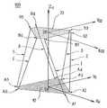
도 1은 헥사포트 터렛의 운동학적 설명도이다.1 is a kinematic explanatory diagram of a hexaport turret.
도 2는 레그와 고정 베이스 사이 링크의 고정 베이스의 배치를 도시하는 도면이다.2 is a view showing the arrangement of the fixing base of the link between the leg and the fixing base.
도 3은 레그와 이동판 사이 링크의 이동판의 배치를 도시하는 도면이다.3 is a diagram showing the arrangement of the movable plate of the link between the legs and the movable plate.
도 4는 이동판과 한 쌍의 레그 사이의 링크의 예시를 도시하는 도면이다.4 is a diagram illustrating an example of a link between a moving plate and a pair of legs.
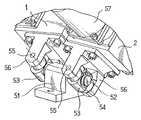
도 5는 고정 베이스와 한 쌍의 레그 사이의 링크의 예시를 도시하는 도면이다.5 is a diagram illustrating an example of a link between a fixed base and a pair of legs.
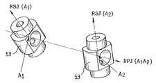
도 6 내지 도 8은 도 4 및 도 5의 연결에 이용되는 서로 다른 기계 구성 요소를 도시하는 도면이다.6 to 8 show different mechanical components used in the connection of FIGS. 4 and 5.
도 9a는 잭에 대한 길이 조절 장치의 단면도이다.9A is a cross-sectional view of the length adjustment device for the jack.
도 9b는 선 A-A를 따라 취한 도 9a의 조절 장치의 단면도이다.9B is a cross-sectional view of the adjusting device of FIG. 9A taken along line A-A.
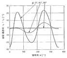
도 10 및 도 11은 이동판의 방향의 함수로서 잭과 베이스 사이의 연결을 만드는 구성 요소의 회전각을 도시하는 그래프이다.10 and 11 are graphs showing the angle of rotation of the components making the connection between the jack and the base as a function of the direction of the moving plate.
도 12는 이동판의 방향의 함수로서 레그를 만드는 2개의 구성 요소 사이의 상대회전각을 도시하는 그래프이다.12 is a graph showing the relative angle of rotation between two components making up a leg as a function of the direction of the moving plate.
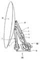
도 13은 파라볼릭 안테나에서 그 기준위치에 장착된 헥사포드 터렛을 도시하 는 도면이다.FIG. 13 shows a hexapod turret mounted at its reference position in a parabolic antenna.
도 14는 공간에 이동판의 방향을 정의하기 위해 이용된 방위-상하각 표시계(system of azimuth-elevation mark)를 도시하는 도면이다.FIG. 14 is a diagram illustrating a system of azimuth-elevation mark used to define the direction of the moving plate in space.
도 15는 헥사포드 터렛이 파라볼릭 안테나에 장착되어, 불안정한 구조로 접근하는 위치에 배치된 상기 터렛을 도시하는 도면이다.FIG. 15 shows the turret in a position where the hexaford turret is mounted on a parabolic antenna and approaches an unstable structure.
도 16 및 도 17은 그 상하각의 함수로서 이동판의 오프셋 규칙의 예시를 도시하는 도면이다.16 and 17 are diagrams showing an example of an offset rule of a moving plate as a function of its upper and lower angles.
도 18은 터렛의 이동판의 변위 원리를 도시하는 도면이다.18 is a diagram showing the principle of displacement of the moving plate of the turret.
도 19 및 도 20은 터렛의 가능한 변위 궤적을 도시하는 도면이다.19 and 20 are diagrams showing possible displacement trajectories of the turret.
도 21은 헥사포드 터렛의 함수의 제어 수단을 실행한 예시를 도시하는 도면이다.FIG. 21 is a diagram showing an example of executing control means for the function of the hexaford turret.
도 1에서 헥사포드 터렛(100)은 레그를 구성하는 6개의 동일 잭(1, 2, 3, 4, 5, 6)에 결합된 베이스(10) 및 이동판(20)을 구비한다. 각각의 잭(i)은 이동판(20)의 점(Bi)에 고정 베이스의 점(Ai)을 연결하며, 거리(AiBi)에 상응하는 길이(Li)로 조절된다. 잭과 베이스(10) 사이의 결합뿐만 아니라 잭과 이동판(20) 사이의 결합은 카르단 형식(cardan type)(또는 유니버셜 조인트(universal joint))의 12개의 조인트로 형성된다. 이들 각각의 조인트는 점(A1, A2, A3,A4,A5,A6,B1, B2, B3, B4, B5,및 B6)을 교차하는 12개의 회전축 요소를 구비한다.In FIG. 1, the
도 2에 도시된 바와 같이, 점(Ai)은 고정 베이스(10)의 중심(OA)으로부터 거리(RA)에 위치되며, 서로에 대해 120°로 위치되는 3 쌍((A1, A2), (A3,A4), (A5,A6))으로 분할된다. 유사하게 도 3에서, 점(Bi)은 이동판(20)의 중심(OB)으로부터 거리(RB)에 위치되며, 서로에 대해 120°로 위치되는 3 쌍((B2, B3), (B4, B5),(B6, B1)으로 분할된다. 베이스(10)상의 한 쌍의 점으로부터 시작하는 2개의 잭은 이동판(20)상의 다른 쌍의 점과 항상 결합된다. 이렇게, 잭(1 내지 6)은 베이스(10)를 향해 또는 이동판(20)을 향해 선택적으로 2개씩 한점에 모인다.As shown in FIG. 2, the points Ai are located at a distance RA from the center OA of the fixed
도 4는 한 쌍의 잭(2, 3)과 이동판(20) 사이에 동일 높이의 점(B2, B3)의 링크장치를 상세히 도시하는 도면이다. 이러한 링크장치는 판(10)위에 나사결합된 중앙 지지체(41, central support)를 구비하여, 방향(B2B3)에 따라 방향된 2개의 원통형 축(42)을 대칭으로 지지한다. 선회 조인트(43, pivot joint)는 축(42)에 장착된다.FIG. 4 is a view showing in detail the linkage of the points B2 , B3 of the same height between the pair of
각각의 조인트(43)는 중앙 지지체(41)의 축(42) 중 어느 하나에 가압고정될 수 있는 보어(bore)를 구비한다. 이 경우에, 피벗 링크는 조인트(43)와 축(42)의 표면 사이에서 직접 접촉되어 개설된다.Each joint 43 has a bore that can be pressure fixed to either of the
마찰을 제한하기 위해 이들 재료의 구성 요소를 선택할 수 있으며, 예컨대 축(42)은 강(steel)과 청동(bronze)의 결합물로 제작될 수 있다. 마찰을 더욱 제한하기 위해서는, 이 링크는 또한 조인트(43)에 장착되는 마찰 베어링(friction bearing) 또는 볼(ball) 또는 니들(needle) 베어링의 요소와 연결되어 만들어질 수 있다. 각각의 조인트(43)는 축(42)의 홈에 장착된 서클립(44, circlip) 및 축(42)의 나사 단부에 장착되는 너트에 의해 축(42)의 평행 이동을 정지할 수 있다.The components of these materials can be selected to limit the friction, for example the
조인트(43)는 그 보어에 수직한 2개의 축(45)을 더 구비한다. 잭(2, 3)의 단부(46)는 조인트(43)를 삽입하고, 조인트(43)의 축(45)이 고정되는 보어를 갖는 2개의 대칭 부분으로 구성된 일반적인 캡 형태를 갖는다. 잭(2, 3)의 캡 형상의 단부(46)는 그 것의 모든 방향 구성에 조인트(43)에 대한 최대 공차를 허용하도록 둥근홈(chamfer)을 갖는다.The joint 43 further has two
도 5는 한 쌍의 잭(1, 2)과 고정 베이스(10) 사이에 동일 높이의 점(A1, A2)의 링크를 상세히 설명하는 도면이다. 이 링크는 도 4에 도시된 잭과 이동판 사이의 링크와 유사하다. 이것은 베이스(10) 위에 나사결합되는 중앙 지지체(51)를 구비하며, 방향(A1A2)으로 배향되는 2개의 동심원 원통형 축(52)을 대칭적으로 지지한다. 선회 조인트(53)는 보어를 가지며, 2개의 수직축(55)은 축(52)에 장착된다. 잭(1, 2)의 단부(56)는 조인트(52)를 삽입하고, 조인트(52)의 축이 고정되는 보어를 갖는 2개의 대칭 부분으로 구성된 일반적인 캡 형상을 갖는다.FIG. 5 is a diagram illustrating in detail the link of the points A1 , A2 of the same height between the pair of
잭(1, 2)의 단부(56)는 잭(1, 2)의 길이(L1, L2)의 제어를 허용하는 장치(57)를 지지한다.The
도 9a는 잭(1)의 길이(L1)를 변화시키도록 서로에 대해 미끄러짐 가능한 2개의 조립체(LA, LB)를 구비하는 잭(1)을 도시한다. 축(42)에 수직하게 배치된 톱니 모양의 휠(64)은 길이 조절 장치(57)가 회전될 수 있는 이음매가 없는 스크류(63, endless screw)를 지지하는 출구 축(62)을 갖는 스텝 모터(61)를 구비한다. 이 톱니모양의 휠(64)은 조립체(LA)의 길이로 연장하는 볼 스크류(65)를 구동한다. 조립체(LB)는 볼 스크류(65)를 선회시키는 솔리드에 장착되는 스크류(66)를 구비한다. 너트(66)에서 볼 스크류(65)의 회전은 스크류(65)를 따라 너트(66)의 평행 이동을 발생시킨다.9a shows a
이 조절 장치에서, 스크류(65)는 스텝 모터(61)의 속도에 비례하는 회전 속도를 갖는다. 이들 속도 사이의 비례 계수를 판정하기 위해, 다양한 기계 요소의 기하학적인 특성(특히, 스크류(65), 휠(64) 및 이음매가 없는 스크류(63)의 피치)을 알 필요가 있다. 이론적으로, 모터(61)의 출구 축(62)의 각 위치(angular position)를 제어하므로 잭(1)의 길이(L1)를 산출한다. 이 길이를 제어하기 위해, 예로서 모터(61)의 자동 개방형-루프 위치(automatic open-loop position) 제어 또는 폐쇄형-루프 자동 제어에 대한 각위치 측정기(resolver)에 의해 축(62)의 절대 위치 측정에 이용될 수 있다. 또한, 광학 코더(optic coder), 또는 증분 또는 절대 코더, 단일 회전 또는 다중 회전 코더를 이용할 수 있다.In this adjusting device, the
그러나, 잭(1)을 연장하는 것은 이 장치에 의해 측정된 각 크기(angular size)에 정비례(direct proportion)하는 것은 아니다. 사실, 이동판(20)의 위치에 대한 변형 중에, LA 및LB 조립체의 상대회전이 야기된다. 이 부가적인 회전은 모터(61)의 작용과 관계없이 나선형 링크(helicoidal link)에 의해 잭(1)의 길이(L1)를 변형시킨다. 이 효과는 모터에 할당된 설정점(set-point)을 산출하는데 고려된다. 상대적인 회전이 점(B1 내지 B6)의 연산된 위치에 따라 분석적으로 판정된다. 중간 연산은 카르단 조인트의 요소의 회전이 판정되는 것을 허용한다.However, extending the
도 6 내지 도 8은 카르단 링크를 만드는 다양한 요소의 회전축을 도시한다. 축(RPJ)는 중앙 지지체(41 또는 51)에 부착되며, 축(RSJ)은 조인트(43 또는 53)에 부착된다.6 to 8 show the axis of rotation of the various elements making up the cardan link. The shaft RPJ is attached to the
도 10은 이동판(20)의 고정된 상하각(β)에 대한 방위각(α)의 함수로서 RPJ 둘레 점(A1)의 동일 높이의 조인트(43)의 회전각을 도시하는 그래프이다. 이와 유사하게, 도 11은 이동판(20)의 고정된 상하각(β)에 대한 방위각(α)의 함수로서 RSJ 둘레 점(A1)의 동일 높이의 잭(1)의 회전각을 도시하는 그래프이다. 최종적으로, 도 12는 이동판(20)의 고정된 상하각(β)에 대한 방위각(α)의 함수로서 잭(1)의 2개의 요소(LA 및 LB) 사이의 상대 회전각을 도시한다.FIG. 10 is a graph showing the rotation angle of the joint 43 of the same height of the RPJ circumferential point A1 as a function of the azimuth angle α with respect to the fixed upper and lower angle β of the moving
도 13에서는, 파라볼릭(parabolic) 안테나(30)를 지지하는 헥사포드 터렛(100)의 기준위치가 도시된다. 이 위치에서, 잭(1, 2, 3, 4, 5, 6)은 모두 동일 길이(L0)로 조절된다. 이 구조에서, 중심(OB)은 수직축(Z0)상의 중심(OA)과 수직하게 위치된다. 또한, 기준 위치는 터렛의 가상 위치로 선택될 수 있다. 예컨대, 기준 위치는 잭이 기계적으로 얻을 수 있는 길이보다 더 긴 길이(L0)로 가정될 수 있는 위치로 정의 될 수 있다.In FIG. 13, the reference position of the
도 14에 도시된 바와 같이, 프레임(R0)은 중심(OA) 및 축(X0, Y0, Z0)의 베이스(10)에 고정되어 정의된다. 이 프레임(R0)에서, 이동판(20)의 위치는 그 중심(OB)의 위치 및 방위각(α)과 상하각(β)에 의해 정의된 지시 방향(V)에 의해 완전히 판정될 수 있다. 중심(OB) 및 축(X0, Y0, Z0)의 프레임(R01)은 축(Z0) 및 방위각(α)에 대해 프레임(R0)의 회전에 의한 이미지로 정의된다. 동일한 방식으로, 중심(OB) 및 축(X02, Y02, Z02)의 프레임(R02)은 축(X01) 및 상하각(β)에 대해 프레임(R01)의 회전에 의한 이미지로 정의된다. 프레임(R02)은 이동판(20)에 대한 고정 프레임이다. 방향(x02)은 프레임(R0)의 지시 방향(V)을 정의한다.As shown in FIG. 14, the frame R0 is defined fixed to the
헥사포드 구조에 대한 이론은 6개의 자유도에 따라 공간에 이동판이 배치되는 것을 가능하게 한다. 그러나 , 특정 위치는 헥사포드 구조의 불안정한 구성을 이끈다. 도 15는 불안정 상태에 접근하는 구성의 헥사포드 터렛(100)을 도시한다. 이 도면에서, 이동판(20)이 잭(1, 2)에 실제로 정렬된다(레그 사이 및 판에 수직한 각은 80°의 한계치에 도달함). 구조(100)는 그 요소 사이의 각(잭(1 내지 6)의 축 사이 및 고정 베이스(10) 또는 이동판(20)의 평면에 수직한 각)이 90°에 접근할 때 그 강성을 잃는다. 이 현상은 특히, 이 구조가 기상 조건이 나쁜 외부에 위치될 때마다 피해를 미친다.The theory of hexaford structure makes it possible to arrange moving plates in space with six degrees of freedom. However, certain positions lead to unstable construction of the hexapod structure. 15 shows a
헥사포드 터렛(100)이 터렛의 치수에 대해 상당한 거리에 위치되는 구성 요소를 향해 포인트 장비로 이용되도록 주어진다면, 그 판(20)의 방향뿐만 아니라 프 레임(R0)의 그 위치에도 관심을 가져야 한다.Given that the
지시 방향(V)은 2개의 방향 매개변수(α, β)를 특징으로 한다. 이동판(20)의 오프셋 규칙(d)은 지시 방향(V) 함수를 지시하도록 정의된다. 예컨대, 이동판(20)의 중심(OB)은 축(Z0)에 수직한 면, 즉 베이스(10)에 대한 높이(Z) 상수에 따라 이동하도록 잭(1 내지 6)의 길이(L1 내지 L6)의 변형량이 제어된다. 이 평면은 점(OB)이 항상 위치되어야 하는 "오프셋 표면"을 정의한다. 주어진 지시 방향(V)에 대해, 점(OB)은 도 13에 도시된 기준 구조에 따라 방향(X01)에 일정 거리(d)로 오프셋된다. 따라서, 오프셋 방향(X01)은 방위각(α)을 따르며, 오프셋 거리(d)는 판의 상하각(β)의 함수이다.The pointing direction V is characterized by two direction parameters α and β. The offset rule d of the moving
도 16 및 도 17은 상하각(β)의 함수로서 오프셋 규칙의 예를 도시한다. 이동판(20)에 위치하는 이 규칙이 고려될 때, 잭(1 내지 6)의 축 사이 및 고정 베이스(10) 또는 이동판(20)의 면에 수직한 각이, 예컨대 항상 45°미만(45°가 안전여유(safty margin)로 주어짐)인 구조에 헥사포드 터렛(100)이 위치된다. 이 규칙은 낮은 강성의 특이점과 터렛(100)이 떨어져 위치되는 것을 가능하게 한다.16 and 17 show examples of offset rules as a function of the upper and lower angles β. When this rule is located on the moving
물론, 적용되는 오프셋(d)을 정의하는 다양한 방법이 있다.Of course, there are various ways to define the offset d applied.
-점(OB)이 이동하는 오프셋 표면의 형식에 따라서, 오프셋 표면은 평면 이외, 예컨대 구 또는 타원체의 일부분 등으로 선택될 수 있으며,Depending on the format of the offset surface at which point OB moves, the offset surface may be selected other than a plane, for example as part of a sphere or ellipsoid,
-이 표면에 위치하는 규칙에 따라서, 오프셋 규칙(d)은 예컨대, 상하각(β)의 함수로 고정될 수 있다.Depending on the rule located on this surface, the offset rule d can be fixed, for example, as a function of the upper and lower angles β.
그렇지만, 이들 선택예에는 조건이 있다. 한편으로는, 성취 가능한 잭(i)의 길이(Li)가 제한된다는 것이다. 사실상, 가능한 최소 및 최대 연장량에 대한 고려가 있어야 한다. 다른 한편으로는, 요소 사이의 각에 관한 안전 여유에 대한 선택이 고려되어야 한다. 예컨대, 135° 또는 150°의 최대 각이 선택될 수 있다.However, these selections have conditions. On the one hand, the length Li of the attainable jacki is limited. In fact, consideration should be given to the minimum and maximum possible extensions. On the other hand, the choice of safety margin with respect to the angle between the elements should be considered. For example, a maximum angle of 135 ° or 150 ° can be selected.
도 18은 터렛(100)의 이동판(20)의 변위를 도시한다. 지시 방향(V1=(α1, β1))으로부터 V1에 근접한 지시 방향(V2=(α2, β2))을 향해 헥사포드 터렛(100)의 이동판(20)을 변위시키기 위해, 하기와 같은 단계를 따른다.18 shows the displacement of the moving
제1 단계에서, 프레임(R02)은 X02= V2가 되도록 배향되어야 한다. 이 프레임(R02)에서, 축(Z0) 상에 고정된 점(PRH)을 통과하는 방향(Y02)의 가상 회전(RH)축이 고려된다. 축(RH)과 각(β2-90°)의 이동판(20)의 가상 회전이 만들어진다. 이 회전은 터렛의 기준 위치(정점(zenith)으로 방향된 판)로부터 지시 방향(V2)에 상응하는 위치로의 이행을 가능하게 한다. 상기 설명된 바와 같이, 기준 위치는 가상으로 될 수 있다.In a first step, the frame R02 should be oriented such that X02 = V2 . In this frame R02 , the axis of virtual rotation RH in the direction Y02 passing through the fixed point PRH on the axis Z0 is considered. A virtual rotation of the moving
제2 단계에서, 이동판(20)의 오프셋은 오프셋 규칙에 기인하여 방위각(α2)의 방향에 따라 판정되며, 이로부터 이 구조의 점(A1 내지 A6) 및 점(B1 내지 B6)의 위치가 추론된다. 이 때문에, 이동판(20)의 가상 이동은 오프셋 표면상의 점(OB)이 감소되는 것을 허용하도록 만들어진다. 헥사포드(100)의 레그(1 내지 6)의 길이(L1 내지 L6)는 판(20)의 이 위치에서 판정된다. 이로부터 오프셋에 의해 방향(V1)으로부터 방향(V2)로의 이동이 요구되는 레그(1 내지 6)의 각각의 연장량이 추론된다.In the second step, the offset of the moving
판정된 시간(t)(예컨대, t = 1초)에서 V1으로부터 V2로 판(20)을 이동시키기 위해, 레그(i)의 각각의 길이 조절 장치는 ΔLi의 잭의 연장량을 조절해야만 한다. 예컨대, ΔLi/t의 잭(i)의 각각의 연장 속도가 제어된다.In order to move the
판(20)의 변위량가 너무 커질 때(예컨대, V1으로부터 V2로의 변위가 1°보다 큼), 터렛(100)은 특이점을 통과할 우려가 있다. 이들 특이점을 회피하기 위해, V1으로부터 V2로의 판(20)의 변위량은 방위각(Δα) 및 상승각(Δβ)의 단위 변위량의 급수(series)로 조직될 수 있다. 각각의 단위 변위량은 지시 방향(Vi)으로부터 Vi에 근접한 지시 방향(Vi+1)으로 변환되는 것을 허용한다. 각각의 단위 변위량 때문에, 잭의 연장량은 이미 기술된 바와 같이, 2개의 연속하는 가상 변환량(가상 평행 이동에 의해 뒤따르는 가상 회전)에 기인하여 연산된다. 이렇게, 판(20)이 Δα 및Δβ의 산포(spread)를 도시하는 지시 방향(V1, ...Vi, Vi+1...V2)에 상응하는 위치의 급수에 따라 이동된다. Δα 및Δβ의 값은 특이점 또는 물리학적으로 창조될 수 없는 구조를 결코 통과할 수 없도록 판(20)에 대해 충분히 낮게 선택된다. 사실상, α 및 β가 낮으면 낮을수록, 판(20)의 연속 위치(OB)가 특이점에 접근할 수 없게 된다.When the displacement amount of the
도 19 및 도 20은 지시 방향(Vi)의 연속 위치를 도시한다. 예컨대, 이들 위치는 1°의 연속 편향(successive deviation)에 의해 선택된다. 2개의 연속 위치 사이의 방향 벡터(Vi)의 단위 궤적은 2개의 연속 방향을 포함하는 면에 수직한 회전축에 상응한다. Vi의 연속 위치는 도 19에 도시된 바와 같이, V1 및 V2에 수직한 축의 회전에 상응하는 직선 전체 궤적 또는 도 20에 도시된 바와 같은 전체 궤적을 따른다.Figure 19 and 20 show the successive positions of the direction (Vi). For example, these positions are selected by successive deviations of 1 °. 2 units locus of the direction vector (Vi) between consecutive position corresponds to a rotational axis perpendicular to the plane including the two consecutive directions. The continuous position of Vi follows a straight overall trajectory corresponding to the rotation of the axes perpendicular to V1 and V2 , as shown in FIG. 19, or a full trajectory as shown in FIG. 20.
물론, 기존에 사용된 표시 시스템에 따른 지시 방향(V)을 특성화하는 방법도 무수히 많이 있다. 본 발명의 방법은 그 방위각 및 상하각에 의한 지시 특성화로 제한되지는 않는다. 또한, 이 좌표계가 지시 방향(V)을 정의하는데 사용되었지만, 방위 및 상하 회전이 기계적으로 재현될 필요는 없다. 다른 회전 및 평행 이동의 결과 방위 및 상하로 정의된 지시 방향이 조절될 수 있다.Of course, there are a myriad of ways to characterize the indication direction V in accordance with a conventionally used display system. The method of the present invention is not limited to the indication characterization by its azimuth and up / down angles. In addition, although this coordinate system was used to define the pointing direction V, the azimuth and the up and down rotation need not be mechanically reproduced. As a result of the other rotations and parallel movements the pointing direction defined by azimuth and up and down can be adjusted.
이미 기술된 헥사포드(100)의 이동판(20)을 변위시키는 방법의 효과는 베이스(10)에 부착된 축(Z0) 둘레의 그 방위 회전에 그 자신의 축(X02)을 중심으로 이동판(20)의 회전에 연결된다. 이동판(20)이 지시방향 V1 = (α1, β1)으로부터 지시방향 V2 = (α2, β2)를 향해 변위될 때, 방위각(α2-α1)의 축(Z0)을 회전시킨다. 상기 기술된 방법에 의해, 이동판(20)은 각(-(α2-α1))의 자신의 축(Z02)을 중심으로 회전하므로 이 방위 회전을 영구히 보상한다. 따라서, 그 결과 축(Z0) 둘레의 이동 판(20)의 총회전은 항상 0(zero)이다.The effect of the method of displacing the moving
본 방법의 이로운 점은, 예컨대 이동판(20)상에 장착되는 장치(30)에 부착되며, 지면에 이 장치를 연결하는 전선이 이동판(20)의 변위중에 결코 비틀림을 받지 않는 것이다. 이 특징은 헥사포드(100)의 기구를 파손시킬 위험 없이 제어되도록 방위축(Z0) 둘레 이동판(20)의 연속 회전을 허용한다. 또한, 이동판의 변위 장치는 선회 조인트를 필요로 하지 않는다.An advantage of the method is that, for example, it is attached to the
본 방법의 또다른 이로운 점은, 변위 장치의 양호한 기능의 연속 제어를 허용하는 것이다. 사실상, 레그의 길이 조절 장치 중의 어느 하나 또는 잭 중의 어느 하나에 결함이 있는 경우에, 가끔 헥사포드의 기능이상을 주지하기가 어렵다. 잭의 정지는 변위 장치의 이동시에 장치를 정지하는 경우에만 해당된다. 그렇지만, 이동 규칙이 더이상 고려되지 않기 때문에, 헥사포드 구조는 유니버셜 조인트에 피할 수 없는 파손을 이끄는 특이점을 통과할 우려가 있다.Another advantage of the method is to allow continuous control of the good functioning of the displacement device. In fact, it is sometimes difficult to notice hexapod dysfunction in the event that either one of the leg length adjusting devices or the jack is defective. Stopping of the jack is only relevant if the device is stopped when the displacement device is moved. However, because the rules of movement are no longer considered, the hexapod structure may pass through singularities that lead to unavoidable breakage in the universal joint.
이들 우려를 회피하기 위하여, 방향 기구는 축(Z0) 둘레 이동판(20)의 총 회전이 항상 0이 되는 것을 보장하기 위한 수단을 구비한다.To avoid these concerns, the direction mechanism is provided with means for ensuring that the total rotation of the moving
마지막으로, 이러한 제어 수단의 예시를 도 21에 설명한다. 이들 수단은 고정 베이스(10)의 중심(OA)에 이동판(20)의 중심(OB)을 연결하는 케이블(80)을 구비한다. 이 케이블(80)은 휨에 대한 유연성(suppleness in flexion) 및 비틀림에 대한 강성(rigidity in torsion)의 특질을 갖는다. 이 케이블은 강성 링크를 통해 이동판(20)의 중심(OB)에 제1 단부, 및 선회 링크(82)를 통해 고정 베이스(10)의 중심(OA)에 제2 단부가 연결된다. 케이블(80)의 제2 단부에는 방향표시장치 소자(84)가 고정된다. 헥사포드(100)의 방향 기구가 정상적으로 작동될 때, 케이블(80)의 제2 단부는 항상 베이스(10)에 대해 고정되어 있으며, 방향표시장치 소자(84)는 검출 회로(86)와 연결된다.Finally, an example of such control means is explained in FIG. These means have a
만약 레그(1, 2, 3, 4, 5, 6)의 길이 조절 장치 중의 어느 하나에 결함이 있거나, 잭 중의 어느 하나에 결합이 있다면, 축(Z0) 둘레 판(20)의 회전은 베이스(10)에 대해 케이블(80)의 회전을 발생시킨다. 이 회전은 방향표시장치 소자(84)의 회전을 구동하여, 장치가 검출 회로(86)와 더 이상 연결되지 않는다. 검출 회로(86)는 접촉의 이러한 차단을 검출하여 레그 조절 장치의 제어 장치로 경고 신호(alert signal)를 송신한다. 이 신호에 응하여, 제어 장치는 헥사포드(100)의 이동을 정지시킨다.If any one of the length adjusting devices of the
다른 형식의 제어 수단이 여기에 사용될 수 있다.Other forms of control means can be used here.
본 발명에 따라 지평선(horizon) 위에 적어도 반-공간(demi-space)을 덮도록 적어도 2π스테라디안(steradian)의 시계 및 상당한 간극에 의해 장비를 배향시키는 헥사포드 장치를 사용할 수 있으며, 또한 본 발명에 의해 처음부터 끝까지 양호한 강성을 유지하며 반-공간의 모든 방향으로 장치를 배향시킬 수 있다.According to the invention it is possible to use hexapod devices which orient the equipment by at least 2π steradian clocks and significant gaps so as to cover at least a demi-space above the horizon, and also the invention This allows the device to be oriented in all directions of the semi-space while maintaining good stiffness from beginning to end.
Claims (25)
Translated fromKoreanApplications Claiming Priority (3)
| Application Number | Priority Date | Filing Date | Title |
|---|---|---|---|
| FR01/07136 | 2001-05-31 | ||
| FR0107136AFR2825445B1 (en) | 2001-05-31 | 2001-05-31 | METHOD OF ORIENTATION OF A HEXAPOD TURRET |
| PCT/FR2002/001816WO2002097920A1 (en) | 2001-05-31 | 2002-05-30 | Method for orienting a hexapod turret |
Publications (2)
| Publication Number | Publication Date |
|---|---|
| KR20030051608A KR20030051608A (en) | 2003-06-25 |
| KR100880290B1true KR100880290B1 (en) | 2009-01-23 |
Family
ID=8863813
Family Applications (1)
| Application Number | Title | Priority Date | Filing Date |
|---|---|---|---|
| KR1020037001452AExpired - Fee RelatedKR100880290B1 (en) | 2001-05-31 | 2002-05-30 | Method and apparatus for displacing moving plate of hexapod turret |
Country Status (6)
| Country | Link |
|---|---|
| US (1) | US7081866B2 (en) |
| EP (1) | EP1396046B9 (en) |
| KR (1) | KR100880290B1 (en) |
| ES (1) | ES2402406T3 (en) |
| FR (1) | FR2825445B1 (en) |
| WO (1) | WO2002097920A1 (en) |
Families Citing this family (13)
| Publication number | Priority date | Publication date | Assignee | Title |
|---|---|---|---|---|
| US7469381B2 (en) | 2007-01-07 | 2008-12-23 | Apple Inc. | List scrolling and document translation, scaling, and rotation on a touch-screen display |
| US7487444B2 (en) | 2002-03-19 | 2009-02-03 | Aol Llc | Reformatting columns of content for display |
| ES2231026A1 (en)* | 2003-10-27 | 2005-05-01 | Ramem, S.A. | Hexapod type positioner for solar tracking of solar concentrators |
| ITRM20050338A1 (en)* | 2005-06-28 | 2006-12-29 | Finmeccanica Spa | ISOSTATIC SUPPORT STRUCTURE FOR ANTENNAS REFLECTORS OF LARGE FIXED OR REINFORCABLE DIMENSIONS. |
| US7671797B1 (en)* | 2006-09-18 | 2010-03-02 | Nvidia Corporation | Coordinate-based system, method and computer program product for adjusting an antenna |
| DE102006046758A1 (en)* | 2006-09-29 | 2008-04-03 | Abb Patent Gmbh | Arrangement, especially for positioning objects, has at least one pair of supports made up of two supports that run parallel one inside the other and together form parallelogram |
| SE530700C2 (en)* | 2006-12-21 | 2008-08-19 | Hexagon Metrology Ab | Method and apparatus for compensating geometric errors in processing machines |
| FR2929195B1 (en)* | 2008-03-27 | 2010-05-07 | Peugeot Citroen Automobiles Sa | CONTROLLED VARIABLE ORIENTATION LIGHTING PROJECTOR FOR MOTOR VEHICLE |
| US8215199B2 (en)* | 2008-11-17 | 2012-07-10 | Marcroft Sacha L | Parallel kinematic positioning system |
| CN103370582A (en) | 2010-11-24 | 2013-10-23 | 威廉·J·帝维利尔 | Solar collector positioning device |
| TWI493148B (en)* | 2011-11-22 | 2015-07-21 | William J Devillier | Solar collector positioning apparatus |
| US9376221B1 (en)* | 2012-10-31 | 2016-06-28 | The Boeing Company | Methods and apparatus to point a payload at a target |
| CN118939010B (en)* | 2024-10-09 | 2025-03-14 | 中国科学院西安光学精密机械研究所 | Nanoradian level space gravitational wave detection beam pointing control system and method |
Citations (2)
| Publication number | Priority date | Publication date | Assignee | Title |
|---|---|---|---|---|
| EP0515888A1 (en)* | 1991-05-29 | 1992-12-02 | ANT Nachrichtentechnik GmbH | Support and pointing arrangement for antennes or telescopes |
| WO1998040761A1 (en)* | 1997-03-11 | 1998-09-17 | Orbit Communications, Tracking And Telemetry Ltd. | Satellite tracking system |
Family Cites Families (5)
| Publication number | Priority date | Publication date | Assignee | Title |
|---|---|---|---|---|
| JPH0742812B2 (en)* | 1986-06-04 | 1995-05-10 | 富士重工業株式会社 | Deployed structure |
| EP0266026A1 (en)* | 1986-08-01 | 1988-05-04 | HER MAJESTY THE QUEEN in right of New Zealand Department of Scientific and Industrial Research | Tracking antenna mount |
| GB9324218D0 (en)* | 1993-11-25 | 1994-01-12 | Renishaw Plc | Position determination machines |
| US6041500A (en)* | 1998-01-23 | 2000-03-28 | Giddings & Lewis, Inc. | Automatic assembly machine and method utilizing six-axis positioning device |
| US6542132B2 (en)* | 2001-06-12 | 2003-04-01 | Harris Corporation | Deployable reflector antenna with tensegrity support architecture and associated methods |
- 2001
- 2001-05-31FRFR0107136Apatent/FR2825445B1/ennot_activeExpired - Fee Related
- 2002
- 2002-05-30EPEP02743335.8Apatent/EP1396046B9/ennot_activeExpired - Lifetime
- 2002-05-30KRKR1020037001452Apatent/KR100880290B1/ennot_activeExpired - Fee Related
- 2002-05-30USUS10/479,648patent/US7081866B2/ennot_activeExpired - Lifetime
- 2002-05-30WOPCT/FR2002/001816patent/WO2002097920A1/ennot_activeApplication Discontinuation
- 2002-05-30ESES02743335Tpatent/ES2402406T3/ennot_activeExpired - Lifetime
Patent Citations (2)
| Publication number | Priority date | Publication date | Assignee | Title |
|---|---|---|---|---|
| EP0515888A1 (en)* | 1991-05-29 | 1992-12-02 | ANT Nachrichtentechnik GmbH | Support and pointing arrangement for antennes or telescopes |
| WO1998040761A1 (en)* | 1997-03-11 | 1998-09-17 | Orbit Communications, Tracking And Telemetry Ltd. | Satellite tracking system |
Also Published As
| Publication number | Publication date |
|---|---|
| EP1396046A1 (en) | 2004-03-10 |
| EP1396046B1 (en) | 2013-01-02 |
| FR2825445B1 (en) | 2004-02-13 |
| ES2402406T3 (en) | 2013-05-03 |
| WO2002097920A1 (en) | 2002-12-05 |
| EP1396046B9 (en) | 2013-07-10 |
| WO2002097920A8 (en) | 2005-04-07 |
| US7081866B2 (en) | 2006-07-25 |
| US20040244525A1 (en) | 2004-12-09 |
| KR20030051608A (en) | 2003-06-25 |
| FR2825445A1 (en) | 2002-12-06 |
Similar Documents
| Publication | Publication Date | Title |
|---|---|---|
| KR100880290B1 (en) | Method and apparatus for displacing moving plate of hexapod turret | |
| US4790718A (en) | Manipulators | |
| US20210010798A1 (en) | Six degree-of-freedom (dof) measuring system and method | |
| US4407625A (en) | Multi-arm robot | |
| US9882276B1 (en) | Pivoting sensor drive system and method | |
| US3987452A (en) | Tracking antenna mount with complete hemispherical coverage | |
| JPH01301082A (en) | Welding robot | |
| US5421096A (en) | Gear driven alidade assembly | |
| CN211475394U (en) | Leveling mechanism and vision imaging system | |
| JP2625547B2 (en) | Mirror support device | |
| US4855564A (en) | Laser beam alignment and transport system | |
| CN103698873B (en) | The catoptron attitude quantitative adjusting method that thick essence combines and regulating device | |
| EP1214632B1 (en) | Machine system having optical endpoint control | |
| KR102129542B1 (en) | Apparatus for measuring a distance about narrow range for bridge structures | |
| EP0660912B1 (en) | Apparatus for the three-dimensional orientation of an object | |
| WO2008035132A1 (en) | A heliostat support and drive mechanism | |
| EP0209216B1 (en) | Stabilised platform arrangement | |
| EP3869611A1 (en) | Articulated mechanism and articulated aiming system comprising the mechanism | |
| US11808567B1 (en) | System and method for detecting span alignment within a mechanized irrigation system | |
| CN213857989U (en) | Position fine adjustment equipment and assembly production line | |
| US6398444B1 (en) | Coupling for airport surveillance antennas and other rotating structures | |
| KR101783885B1 (en) | Auto optical alignment apparatus of target adjunct system | |
| JP2638946B2 (en) | Positioning device | |
| WO2012131741A1 (en) | Sun follower with parallel kinematics and process for controlling such follower | |
| CN221422072U (en) | Foundation pit stability measuring device |
Legal Events
| Date | Code | Title | Description |
|---|---|---|---|
| PA0105 | International application | St.27 status event code:A-0-1-A10-A15-nap-PA0105 | |
| T11-X000 | Administrative time limit extension requested | St.27 status event code:U-3-3-T10-T11-oth-X000 | |
| T11-X000 | Administrative time limit extension requested | St.27 status event code:U-3-3-T10-T11-oth-X000 | |
| T13-X000 | Administrative time limit extension granted | St.27 status event code:U-3-3-T10-T13-oth-X000 | |
| P11-X000 | Amendment of application requested | St.27 status event code:A-2-2-P10-P11-nap-X000 | |
| P13-X000 | Application amended | St.27 status event code:A-2-2-P10-P13-nap-X000 | |
| PG1501 | Laying open of application | St.27 status event code:A-1-1-Q10-Q12-nap-PG1501 | |
| A201 | Request for examination | ||
| P11-X000 | Amendment of application requested | St.27 status event code:A-2-2-P10-P11-nap-X000 | |
| P13-X000 | Application amended | St.27 status event code:A-2-2-P10-P13-nap-X000 | |
| PA0201 | Request for examination | St.27 status event code:A-1-2-D10-D11-exm-PA0201 | |
| E902 | Notification of reason for refusal | ||
| PE0902 | Notice of grounds for rejection | St.27 status event code:A-1-2-D10-D21-exm-PE0902 | |
| P11-X000 | Amendment of application requested | St.27 status event code:A-2-2-P10-P11-nap-X000 | |
| P13-X000 | Application amended | St.27 status event code:A-2-2-P10-P13-nap-X000 | |
| E701 | Decision to grant or registration of patent right | ||
| PE0701 | Decision of registration | St.27 status event code:A-1-2-D10-D22-exm-PE0701 | |
| GRNT | Written decision to grant | ||
| PR0701 | Registration of establishment | St.27 status event code:A-2-4-F10-F11-exm-PR0701 | |
| PR1002 | Payment of registration fee | St.27 status event code:A-2-2-U10-U12-oth-PR1002 Fee payment year number:1 | |
| PG1601 | Publication of registration | St.27 status event code:A-4-4-Q10-Q13-nap-PG1601 | |
| PN2301 | Change of applicant | St.27 status event code:A-5-5-R10-R11-asn-PN2301 | |
| PN2301 | Change of applicant | St.27 status event code:A-5-5-R10-R14-asn-PN2301 | |
| PR1001 | Payment of annual fee | St.27 status event code:A-4-4-U10-U11-oth-PR1001 Fee payment year number:4 | |
| FPAY | Annual fee payment | Payment date:20121214 Year of fee payment:5 | |
| PR1001 | Payment of annual fee | St.27 status event code:A-4-4-U10-U11-oth-PR1001 Fee payment year number:5 | |
| FPAY | Annual fee payment | Payment date:20131213 Year of fee payment:6 | |
| PR1001 | Payment of annual fee | St.27 status event code:A-4-4-U10-U11-oth-PR1001 Fee payment year number:6 | |
| FPAY | Annual fee payment | Payment date:20150120 Year of fee payment:7 | |
| PR1001 | Payment of annual fee | St.27 status event code:A-4-4-U10-U11-oth-PR1001 Fee payment year number:7 | |
| FPAY | Annual fee payment | Payment date:20160112 Year of fee payment:8 | |
| PR1001 | Payment of annual fee | St.27 status event code:A-4-4-U10-U11-oth-PR1001 Fee payment year number:8 | |
| FPAY | Annual fee payment | Payment date:20170112 Year of fee payment:9 | |
| PR1001 | Payment of annual fee | St.27 status event code:A-4-4-U10-U11-oth-PR1001 Fee payment year number:9 | |
| FPAY | Annual fee payment | Payment date:20171213 Year of fee payment:10 | |
| PR1001 | Payment of annual fee | St.27 status event code:A-4-4-U10-U11-oth-PR1001 Fee payment year number:10 | |
| FPAY | Annual fee payment | Payment date:20181227 Year of fee payment:11 | |
| PR1001 | Payment of annual fee | St.27 status event code:A-4-4-U10-U11-oth-PR1001 Fee payment year number:11 | |
| R18-X000 | Changes to party contact information recorded | St.27 status event code:A-5-5-R10-R18-oth-X000 | |
| PR1001 | Payment of annual fee | St.27 status event code:A-4-4-U10-U11-oth-PR1001 Fee payment year number:12 | |
| PN2301 | Change of applicant | St.27 status event code:A-5-5-R10-R13-asn-PN2301 St.27 status event code:A-5-5-R10-R11-asn-PN2301 | |
| PC1903 | Unpaid annual fee | St.27 status event code:A-4-4-U10-U13-oth-PC1903 Not in force date:20210117 Payment event data comment text:Termination Category : DEFAULT_OF_REGISTRATION_FEE | |
| PC1903 | Unpaid annual fee | St.27 status event code:N-4-6-H10-H13-oth-PC1903 Ip right cessation event data comment text:Termination Category : DEFAULT_OF_REGISTRATION_FEE Not in force date:20210117 |