KR100877792B1 - Dosing device fixed to prevent rotation - Google Patents
Dosing device fixed to prevent rotationDownload PDFInfo
- Publication number
- KR100877792B1 KR100877792B1KR1020047001727AKR20047001727AKR100877792B1KR 100877792 B1KR100877792 B1KR 100877792B1KR 1020047001727 AKR1020047001727 AKR 1020047001727AKR 20047001727 AKR20047001727 AKR 20047001727AKR 100877792 B1KR100877792 B1KR 100877792B1
- Authority
- KR
- South Korea
- Prior art keywords
- rotary
- setting member
- stoppers
- stopper
- dose
- Prior art date
- Legal status (The legal status is an assumption and is not a legal conclusion. Google has not performed a legal analysis and makes no representation as to the accuracy of the status listed.)
- Expired - Fee Related
Links
Images


Classifications
- A—HUMAN NECESSITIES
- A61—MEDICAL OR VETERINARY SCIENCE; HYGIENE
- A61M—DEVICES FOR INTRODUCING MEDIA INTO, OR ONTO, THE BODY; DEVICES FOR TRANSDUCING BODY MEDIA OR FOR TAKING MEDIA FROM THE BODY; DEVICES FOR PRODUCING OR ENDING SLEEP OR STUPOR
- A61M5/00—Devices for bringing media into the body in a subcutaneous, intra-vascular or intramuscular way; Accessories therefor, e.g. filling or cleaning devices, arm-rests
- A61M5/178—Syringes
- A61M5/31—Details
- A61M5/315—Pistons; Piston-rods; Guiding, blocking or restricting the movement of the rod or piston; Appliances on the rod for facilitating dosing ; Dosing mechanisms
- A61M5/31533—Dosing mechanisms, i.e. setting a dose
- A61M5/31545—Setting modes for dosing
- A61M5/31548—Mechanically operated dose setting member
- A61M5/3155—Mechanically operated dose setting member by rotational movement of dose setting member, e.g. during setting or filling of a syringe
- A61M5/31553—Mechanically operated dose setting member by rotational movement of dose setting member, e.g. during setting or filling of a syringe without axial movement of dose setting member
- A—HUMAN NECESSITIES
- A61—MEDICAL OR VETERINARY SCIENCE; HYGIENE
- A61M—DEVICES FOR INTRODUCING MEDIA INTO, OR ONTO, THE BODY; DEVICES FOR TRANSDUCING BODY MEDIA OR FOR TAKING MEDIA FROM THE BODY; DEVICES FOR PRODUCING OR ENDING SLEEP OR STUPOR
- A61M5/00—Devices for bringing media into the body in a subcutaneous, intra-vascular or intramuscular way; Accessories therefor, e.g. filling or cleaning devices, arm-rests
- A61M5/178—Syringes
- A61M5/31—Details
- A61M5/315—Pistons; Piston-rods; Guiding, blocking or restricting the movement of the rod or piston; Appliances on the rod for facilitating dosing ; Dosing mechanisms
- A—HUMAN NECESSITIES
- A61—MEDICAL OR VETERINARY SCIENCE; HYGIENE
- A61M—DEVICES FOR INTRODUCING MEDIA INTO, OR ONTO, THE BODY; DEVICES FOR TRANSDUCING BODY MEDIA OR FOR TAKING MEDIA FROM THE BODY; DEVICES FOR PRODUCING OR ENDING SLEEP OR STUPOR
- A61M5/00—Devices for bringing media into the body in a subcutaneous, intra-vascular or intramuscular way; Accessories therefor, e.g. filling or cleaning devices, arm-rests
- A61M5/14—Infusion devices, e.g. infusing by gravity; Blood infusion; Accessories therefor
- A61M5/142—Pressure infusion, e.g. using pumps
- A61M5/145—Pressure infusion, e.g. using pumps using pressurised reservoirs, e.g. pressurised by means of pistons
- A61M5/1452—Pressure infusion, e.g. using pumps using pressurised reservoirs, e.g. pressurised by means of pistons pressurised by means of pistons
- A61M5/14566—Pressure infusion, e.g. using pumps using pressurised reservoirs, e.g. pressurised by means of pistons pressurised by means of pistons with a replaceable reservoir for receiving a piston rod of the pump
- A—HUMAN NECESSITIES
- A61—MEDICAL OR VETERINARY SCIENCE; HYGIENE
- A61M—DEVICES FOR INTRODUCING MEDIA INTO, OR ONTO, THE BODY; DEVICES FOR TRANSDUCING BODY MEDIA OR FOR TAKING MEDIA FROM THE BODY; DEVICES FOR PRODUCING OR ENDING SLEEP OR STUPOR
- A61M5/00—Devices for bringing media into the body in a subcutaneous, intra-vascular or intramuscular way; Accessories therefor, e.g. filling or cleaning devices, arm-rests
- A61M5/178—Syringes
- A61M5/24—Ampoule syringes, i.e. syringes with needle for use in combination with replaceable ampoules or carpules, e.g. automatic
- A—HUMAN NECESSITIES
- A61—MEDICAL OR VETERINARY SCIENCE; HYGIENE
- A61M—DEVICES FOR INTRODUCING MEDIA INTO, OR ONTO, THE BODY; DEVICES FOR TRANSDUCING BODY MEDIA OR FOR TAKING MEDIA FROM THE BODY; DEVICES FOR PRODUCING OR ENDING SLEEP OR STUPOR
- A61M5/00—Devices for bringing media into the body in a subcutaneous, intra-vascular or intramuscular way; Accessories therefor, e.g. filling or cleaning devices, arm-rests
- A61M5/178—Syringes
- A61M5/31—Details
- A61M5/315—Pistons; Piston-rods; Guiding, blocking or restricting the movement of the rod or piston; Appliances on the rod for facilitating dosing ; Dosing mechanisms
- A61M5/31501—Means for blocking or restricting the movement of the rod or piston
- A—HUMAN NECESSITIES
- A61—MEDICAL OR VETERINARY SCIENCE; HYGIENE
- A61M—DEVICES FOR INTRODUCING MEDIA INTO, OR ONTO, THE BODY; DEVICES FOR TRANSDUCING BODY MEDIA OR FOR TAKING MEDIA FROM THE BODY; DEVICES FOR PRODUCING OR ENDING SLEEP OR STUPOR
- A61M5/00—Devices for bringing media into the body in a subcutaneous, intra-vascular or intramuscular way; Accessories therefor, e.g. filling or cleaning devices, arm-rests
- A61M5/178—Syringes
- A61M5/31—Details
- A61M5/315—Pistons; Piston-rods; Guiding, blocking or restricting the movement of the rod or piston; Appliances on the rod for facilitating dosing ; Dosing mechanisms
- A61M5/31533—Dosing mechanisms, i.e. setting a dose
- A61M5/31535—Means improving security or handling thereof, e.g. blocking means, means preventing insufficient dosing, means allowing correction of overset dose
- A—HUMAN NECESSITIES
- A61—MEDICAL OR VETERINARY SCIENCE; HYGIENE
- A61M—DEVICES FOR INTRODUCING MEDIA INTO, OR ONTO, THE BODY; DEVICES FOR TRANSDUCING BODY MEDIA OR FOR TAKING MEDIA FROM THE BODY; DEVICES FOR PRODUCING OR ENDING SLEEP OR STUPOR
- A61M5/00—Devices for bringing media into the body in a subcutaneous, intra-vascular or intramuscular way; Accessories therefor, e.g. filling or cleaning devices, arm-rests
- A61M5/178—Syringes
- A61M5/31—Details
- A61M5/315—Pistons; Piston-rods; Guiding, blocking or restricting the movement of the rod or piston; Appliances on the rod for facilitating dosing ; Dosing mechanisms
- A61M5/31565—Administration mechanisms, i.e. constructional features, modes of administering a dose
- A61M5/31576—Constructional features or modes of drive mechanisms for piston rods
- A61M5/31578—Constructional features or modes of drive mechanisms for piston rods based on axial translation, i.e. components directly operatively associated and axially moved with plunger rod
- A61M5/3158—Constructional features or modes of drive mechanisms for piston rods based on axial translation, i.e. components directly operatively associated and axially moved with plunger rod performed by axially moving actuator operated by user, e.g. an injection button
Landscapes
- Health & Medical Sciences (AREA)
- Vascular Medicine (AREA)
- Engineering & Computer Science (AREA)
- Anesthesiology (AREA)
- Biomedical Technology (AREA)
- Heart & Thoracic Surgery (AREA)
- Hematology (AREA)
- Life Sciences & Earth Sciences (AREA)
- Animal Behavior & Ethology (AREA)
- General Health & Medical Sciences (AREA)
- Public Health (AREA)
- Veterinary Medicine (AREA)
- Infusion, Injection, And Reservoir Apparatuses (AREA)
Abstract
Translated fromKoreanDescription
Translated fromKorean본 발명은 유체 제품을 다른 투약량들로 투여하기 위한 투여장치에 관한 것이다. 본 발명에 따른 장치의 바람직한 예들은 주사장치이고 특히 주사 펜들이다. 특히 바람직한 예들은 반-폐기성 펜들이다. 상기 장치는 또한 흡입장치 또는 구강 섭취 또는 다른 형태의 유체 제품 투여를 위한 장치의 투약량 조절 부분을 형성할 수 있다.The present invention relates to a dosing device for administering a fluid product in different dosages. Preferred examples of the device according to the invention are injection devices and in particular injection pens. Particularly preferred examples are semi-disposable pens. The device may also form a dosage control portion of the device for inhalation or oral ingestion or for other forms of fluid product administration.
특히 의학적인 용도들에 있어서 제품을 투여할 때, 제품의 투약량을 정확하게 결정하는 것이 매우 중요하게 된다. 주사장치에 의해 전형적으로 대표되는 바와 같은 투여장치에 있어서는, 제품은 대체로 반송 장치와 계합되는 투약량 세팅 부재의 도움으로 투약량이 조절된다. 그러한 장치에 있어서, 투약량 세팅 부재에 의한 투약량 조절 이동이 상기 계합에 기인하여 반송장치에 의한 응답 이동을 유발시킬 때, 특히 상기와 같은 응답 이동이 정확한 투약량 조절과 관련하여 방지되어져야 하는 경우에, 문제가 발생될 수 있다.When administering a product, especially in medical applications, it is very important to accurately determine the dosage of the product. In dosage devices, as typically represented by an injection device, the product is generally dose controlled with the aid of a dosage setting member engaged with the delivery device. In such a device, when the dose adjustment movement by the dose setting member causes a response movement by the conveying device due to the engagement, especially when such a response movement should be prevented in connection with the correct dose adjustment, Problems may arise.
본 발명의 목적은 반송 장치 및 투약량을 선택하기 위한 목적으로 상기 반송 장치에 결합되는 투약량 세팅 부재를 구비하는 투여장치에 있어서 투약량 조절의 정확도를 향상시킴에 있다.It is an object of the present invention to improve the accuracy of dosage adjustment in a dosage device having a dosage setting member coupled to the conveying device for the purpose of selecting a delivery device and dosage.
본 발명은 유체 제품을 다른 투약량으로 투여하기 위한 투여장치에 관한 것이고; 동 투여장치는 제품을 위한 저장기를 갖는 케이싱, 반송 장치, 상기 반송장치에 기계적으로 결합되는 투약량 세팅 부재, 및 상기 투약량 세팅 부재를 위한 스토퍼를 구비한다. 반송 장치는 종동 장치 및 구동 장치에 의해 형성된다. 종동 장치는, 상기 투약량 세팅 부재의 도움으로 사전에 선택된 제품 투약량을 반송하기 위해 병진축을 따른 전진방향에서의 반송 행정의 형태를 취하는 반송 이동을 행할 수 있도록, 케이싱에 의해 장착된다. 종동 장치의 반송 이동은 구동 장치의 도움으로 실시되며, 즉 구동 장치 및 종동 장치는 대응적으로 결합된다. 상기 투약량 세팅 부재는, 투약량 세팅 부재 및 종동 장치가 상기 병진축을 중심으로 서로에 대해 수행하는 회전적인 투약량 조절 이동이 종동 장치 및 케이싱에 대한 상기 병진축을 따른 투약량 세팅 부재의 병진적인 투약량 조절 이동을 필연적으로 도출해내도록, 상기 종동 장치에 결합된다.The present invention relates to a dosing device for administering a fluid product at a different dosage; The dosing device includes a casing having a reservoir for the product, a conveying device, a dosage setting member mechanically coupled to the conveying device, and a stopper for the dosage setting member. The conveying device is formed by a driven device and a driving device. The driven device is mounted by a casing so that a conveying movement in the form of a conveying stroke in the advancing direction along the translational axis can be carried out in order to convey the product dose previously selected with the aid of the dose setting member. The conveying movement of the driven device is carried out with the aid of the drive device, ie the drive device and the driven device are correspondingly combined. The dose setting member is characterized in that the rotational dose adjustment movement that the dose setting member and the driven device perform with respect to each other about the translation axis inevitably results in a translational dose control movement of the dose setting member along the translation axis relative to the driven device and the casing. Coupled to the follower device to elicit.
상기 투여장치는 또한 투약량 세팅 부재를 위한 병진 스토퍼를 구비하며, 상기 투약량 세팅 부재는 축방향 단부 위치에서 축방향에서 마주보도록 병진 스토퍼의 맞은 편에 위치된다. 그러므로, 병진 스토퍼는 병진축을 따른 하나의 방향에서의 투약량 세팅 부재의 가능한 이동을 제한한다. 그러므로, 투약량 세팅 부재의 축방향 단부 위치는 선택가능한 최대 투약량 또는 0의 투약량일 수 있는 최소 투약량에 일치한다. 따라서, 상기 병진 스토퍼는, 전진 방향과 관련하여, 전방 병진 스토 퍼 또는 후방 병진 스토퍼일 수 있다.The dosing device also has a translational stopper for the dosage setting member, which is positioned opposite the translational stopper to face in the axial direction at an axial end position. Therefore, the translational stopper limits the possible movement of the dose setting member in one direction along the translational axis. Therefore, the axial end position of the dose setting member corresponds to the minimum dose, which may be the maximum selectable dose or zero dose. Thus, the translational stopper may be a forward translational stopper or a rearward translational stopper with respect to the forward direction.
만약, 투약량 세팅 부재가 회전식 투약 이동(움직임)을 하고, 그러나, 어떤 이유로 인하여 구동된 장치와의 결합으로 초래되는 병진 투약 이동을 할 수 없다면, 구동된 장치는 축 방향 응답 이동을 행하여야 한다(단, 이러한 응답 이동의 수행이 차단되지 않은 상태라면). 그러나, 어떤 응답 이동을 차단하는 것은 블록에 손상을 주거나 구동된 장치와 투약량 세팅 부재간의 결합 관계에도 손상을 줄 수 있다. 이러한 상황은 특히 투약량 세팅 부재가 병진 스토퍼에 대하여 그 인용된 축 종단 위치를 차지할 때 발생한다.If the dose setting member makes a rotary dose movement (movement), but for some reason the translational dose movement resulting from engagement with the driven device is not possible, then the driven device must make an axial response movement ( Provided that this response move is not blocked). However, blocking any response movement can damage the block or damage the engagement relationship between the driven device and the dose setting member. This situation especially arises when the dose setting member occupies its quoted axial end position with respect to the translational stopper.
허용되지 않은 큰 힘(이 힘은 구동된 장치에 손상을 가하거나 구동된 장치에 의하여 비바람직한 응답 이동을 초래할 수 있다)이 발생하지 않도록 하기 위하여, 본 발명에서는 회전 블록이 제공된다. 회전 블록은 투약량 세팅 부재의 축 종단부내에서만 동작하며, 그리고 종단 위치내에서 첫번째 회전 방향으로 투약량 세팅 부재의 회전식 투약 이동만을 허용한다(즉, 이와 다른 두번째 회전 방향으로의 회전 투약량 이동은 차단한다). 차단된 회전 투약 이동이 만약 차단되지 않는다면 병진 스토퍼에 대하여 축 방향으로 압착된 투약량 세팅 부재를 초래할 것이다. 만약, 회전 투약 이동이 두번째 회전 방향으로 이루어 지고, 병진 스토퍼에 의하여 불가피한 병진 이동이 동시에 차단된다면, 본 발명에 따른 회전 블록없이, 투약량 세팅 부재는 병진 스토퍼와이 관계에서 점증하는 힘에 의하여 압착될 것이다. 그러나, 본 발명의 회전 블록은 이러한 압착력이 허용할 수 없는 값까지 상승하는 것을 방지하거나 심지어는 전혀 상승하지 못하도록 한다.In order to prevent the generation of unacceptable large forces, which can damage the driven device or cause undesired response movement by the driven device, a rotating block is provided in the present invention. The rotary block operates only within the axial end of the dose setting member and only permits rotational dose movement of the dose setting member in the first rotational direction in the longitudinal position (ie blocks rotational dose movement in the other second rotational direction). . A blocked rotational dose movement will result in a dose setting member axially compressed relative to the translational stopper if not blocked. If the rotational dosage movement is made in the second rotational direction and the unavoidable translational movement is simultaneously blocked by the translational stopper, without the rotational block according to the invention, the dosage setting member will be squeezed by an increasing force in this relationship with the translational stopper. . However, the rotating block of the present invention prevents this pressing force from rising to an unacceptable value or even not at all.
구동된 장치와 투약량 세팅 부재간의 결합은 구동된 장치가 투약량 세팅 부재와 직접 체결되는 방식으로 구현된다. 또한, 상기 결합에 의하여 구동된 장치와 투약량 세팅 부재는 함께 전진 방향으로만 이동할 수 있다. 만약 구동 장치가 투약량 세팅 부재상에서 동작하게 되면, 투약량 세팅 부재가 구동된 다음에 구동된 장치가 전진 방향으로 따라온다(즉, 투약량 세팅 부재는 구동된 장치를 종석시킨다). 만약 구동 장치가 구동된 장치상에서 동작하면, 구동된 장치는 트약량 세팅 부재를 종속시킨다.Coupling between the driven device and the dosage setting member is implemented in such a way that the driven device is directly engaged with the dosage setting member. In addition, the device driven by the combination and the dose setting member can only move together in the forward direction. If the drive device is operated on the dose setting member, the dose setting member is driven and then the driven device follows in the forward direction (i.e. the dose setting member terminates the driven device). If the driving device operates on the driven device, the driven device subjects the dose setting member.
회전식 투약 이동은 불가피하게 구동된 장치와 투약량 세팅 부재간에 상대적 이동을 초래한다. 전술한 결합은 특히 나사 조인트를 포함하거나 하나의 나사 조인트만으로 형성할 수 있다. 특히 바람직한 실시예에 있어서, 나사 조인트는 직접적인 나사계입으로 이루어 질 수 있는 데, 여기서 구동 장치와 투약량 세팅 부재의 상호체결 나사의 나사축은 병진축과 매우 용이하게 일치한다.Rotating dose movement inevitably results in relative movement between the driven device and the dose setting member. The above-mentioned combination may in particular comprise a screw joint or be formed of only one screw joint. In a particularly preferred embodiment, the screw joint can be made by direct threading, wherein the screw axis of the interlocking screw of the drive device and the dose setting member is very easily coincident with the translation axis.
전진 방향과 관련하여, 병진 스토퍼는 구동 장치와 투약량 세팅 부재가 전진방향으로 함께 이동하는 차단하는 전방 스토퍼일 수 있으며, 이러한 기능으로 때문에 아래에서는 반송 스토퍼로 언급되고 있다. 이러한 반송 스토퍼는 케이싱으로 직접 형성되거나 케이싱에 정확하게 결합되거나 또는 움직이지 않도록 케이싱에 의하여 탑재되는 것이 바람직하다. 그러나, 병진 스토퍼는 투약량 세팅 부재의 병진 투약 이동을 제한하는 전진 방향에 대하여 후방 스토퍼가 될 수도 있다. 특별히 바람직한 실시예에 있어서, 반송 스토퍼와 후방 병진 스토퍼는 결합되어 제공되며, 투약량 세팅 부재는 (본 케이스에서 설명된) 2 개의 축 단부에 있는 각 병진 스토퍼 의 반대편에 축 방향으로 위치한다. 즉, 투약량 세팅 부재는 2 개의 병진 스토퍼에 카운터 스토퍼를 형성한다. 비록 반송 스토퍼는 구동된 장치와 투약량 세팅 부재의 움직임을 실질적인 접촉에 의하여 제한하지만, 이러한 기능은 후방 병진 스토퍼에는 필요하지 않을 수도 있다. 투약량 세팅 부재가 후방 병진 스토퍼를 축방향으로 밀기 전에, 후방 병진 스토퍼쪽으로 향하는 투약량 세팅 부재의 병진 투약 이동을 사전에 차단할 수 있도록 본 발명에 따른 회전 블록을 매우 정확하게 형성할 수 있다. 청구항에 기재된 문구, 즉 투약량 세팅 부재는 축 종단부에서 축을 따라 마주 대하도록 병진 스토퍼의 반대편에 위치한다는 문구는, 한편으로는 축방향으로 소정의 힘이 가해지는 접촉이 발생한다는 것을 의미하고 다른 한편으로는 이러한 접축이 발생하기 전에 회전 블록이 동작한다는 것을 의미한다.With regard to the forward direction, the translational stopper may be a front stopper which blocks the drive device and the dose setting member moving together in the forward direction, and because of this function it is referred to below as the conveying stopper. Such a conveying stopper is preferably formed by the casing so as to be formed directly into the casing or to be precisely coupled to the casing or not to move. However, the translational stopper may be a rear stopper with respect to the advancing direction which limits the translational dosage movement of the dosage setting member. In a particularly preferred embodiment, the conveying stopper and the rear translation stopper are provided in combination, and the dose setting member is located axially opposite the respective translation stoppers at the two axial ends (described in this case). That is, the dosage setting member forms a counter stopper on the two translational stoppers. Although the conveying stopper limits the movement of the driven device and the dose setting member by substantial contact, this function may not be necessary for the rearward translational stopper. Before the dose setting member pushes the rear translation stopper in the axial direction, the rotary block according to the invention can be formed very precisely so as to prevent the translational dose movement of the dosage setting member towards the rear translation stopper in advance. The phrase recited in the claims, ie that the dose setting member is located opposite the translational stopper so as to face along the axis at the axial end, means that on the one hand a contact with a predetermined force in the axial direction occurs and This means that the rotating block is operated before this contact occurs.
바람직한 실시예에 있어서, 만약 병진 스토퍼가 후방 스토퍼라면, 병진 스토퍼는 케이싱에 의하여 형성되거나 축 방향으로 따라 움직이지 못하도록 케이싱에 의하여 탑재될 수 있다. 다른 실시에에서, 구동 장치는 후방 병진 스토퍼를 직접 형성가능하며, 또한 후방 병진 스토퍼는 구동 장치에 의하여 탑재되어 구동 장치와 관련하여서는 축 방향으로 움직일 수 없다.In a preferred embodiment, if the translational stopper is a rear stopper, the translational stopper may be formed by the casing or mounted by the casing to prevent movement along the axial direction. In another embodiment, the drive device can directly form a rear translation stopper, and the rear translation stopper is mounted by the drive device and cannot move in the axial direction with respect to the drive device.
제 1 실시예에서, 투약량 세팅 부재는 케이싱과 관련된 병진축에 대하여 회전할 수 없는 대신에 구동된 장치는 케이싱과 투약량 세팅 부재에 관련된 병진축에 대하여 회전하여 회전성 투약 이동을 수행할 수 있으며, 여기서, 회전 블록은 투약량 세팅 부재와 이송 부재 사이 또는 투약량 세팅 부재와 구동 장치 사이에 형성될 수 있다. 이송 부재는 회전운동에 대하여 안정된 상태를 유지하면서 구동된 장치에 연결되고 또한 축방향으로 움직이도록 케이싱과 연결된다. 이송 부재는 구동된 장치가 전진 방향과 반대 방향으로 움직이지 못하도록 하는 블록킹 수단에 의하여 형성되는 것이 바람직하다. 본 실시예에서, 구동 장치는 회전 움직임에 대하여 안정된 상태로 안착되어 구동된 장치에 연결되지만, 구동된 장치와 관련하여 축방향으로 움직일 수 있도록 하여 한편으로는 회전성 투약 이동을 가능하게 하고 다른 한편으로는 운반 스트로크를 가능하게 한다.In the first embodiment, the dosage setting member cannot rotate about the translation axis associated with the casing, but the driven device can rotate about the translation axis associated with the casing and the dosage setting member to perform a rotatable dosage movement, Here, the rotary block can be formed between the dose setting member and the transfer member or between the dose setting member and the drive device. The conveying member is connected to the driven device while maintaining a stable state with respect to the rotational movement and is connected with the casing to move in the axial direction. The conveying member is preferably formed by blocking means for preventing the driven device from moving in the direction opposite to the forward direction. In the present embodiment, the drive device is seated in a stable state with respect to the rotational movement and is connected to the driven device, but allows axial movement with respect to the driven device, on the one hand to enable rotatable dosage movement and on the other hand Allows for a carrying stroke.
제 2 실시예에 있어서, 투약량 세팅 부재는 케이싱 및 구동된 장치에 관계된 병진축에 대하여 회전 가능하며, 이는 회전성 투약 이동을 가능하게 하기 위함이다. 그리고, 구동된 장치는 케이싱과 연관되어 회전하지 않도록 하는 것이 바람직하며, 회전 블록은 투약량 세팅 부재와 케이싱 사이에 형성된다.In a second embodiment, the dosage setting member is rotatable about a translation axis relative to the casing and the driven device, to enable rotatable dosage movement. The driven device is then preferably associated with the casing so as not to rotate, wherein the rotating block is formed between the dose setting member and the casing.
비록 회전 블록은 마찰 체결부를 사용하여 이루어지는 것이 원칙이지만, 유효 체결부로 구성하는 것이 바람직하다. 따라서, 회전 블록은, 차단될 예정인 회전 식 투여 이동의 회전 방향으로, 상호 접하여 마주 대하는 스토퍼 영역을 형성하는 적어도 2 개의 회전 스토퍼를 구비한다. 또한, 적어도 2 개의 상호 동작하는 회전 스토퍼가 형성되어 다른 회전 방향으로도 회전식 투약 이동을 가능하게 하며, 이러한 동작을 전혀 차단하지 않는 것이 바람직하다. 가능하다면, 회전 방향에 대하여 탄력적으로 적용할 수 있도록 (함께) 상호 동작하는 회전 스토퍼를 디자인하는 것이 원칙적으로 가능하다. 그러나, 한편에서는 회전 스토퍼, 다른 한편에서는 회전 투약 이동을 병진 투약 이동으로 교체하는 것을 서로 조절함으로써, 블록킹 목적으로 사용되는 상호 동작하는 회전 스토퍼들은 차단되지 않은 회전 투약 이동에 의하 여 빠른 속도로 이동하여 멀어지기 때문에 예정되어 있는 회전 투약 이동을 방해할 수 없다. 이러한 목적은 상호 동작하는 회전 스토퍼의 축 방향 연장부를 조절하여 매우 용이하게 얻을 수 있다.Although the rotating block is made of a frictional fastening in principle, it is preferable to constitute an effective fastening. Thus, the rotary block has at least two rotary stoppers which, in the direction of rotation of the rotary dose movement, which are to be blocked, form a mutually opposite stopper region. In addition, it is preferred that at least two mutually acting rotary stoppers are formed to enable rotary dosing movements in other rotational directions, and not to block these operations at all. If possible, it is possible in principle to design mutually cooperating rotary stoppers so that they can be flexibly adapted to the direction of rotation. However, by controlling each other to replace the rotary stopper on the one hand and the translational dosing movement on the other hand, the interactive rotary stoppers used for blocking purposes move at high speed by means of an unblocked rotary dosing move. Because it is far away, it cannot prevent the intended rotational medication movement. This object can be obtained very easily by adjusting the axial extension of the cooperating rotary stopper.
블로킹을 위하여 상호 함께 동작하는 회전 스토퍼는 투약량 세팅 부재와 바디(바디는 투약량 세팅 부재와 함께 상호 동작하는 회전 스토퍼를 형성한다)의 표면적상에 서로 방사형으로 마주 보도록 형성할 수 있다.The rotary stoppers cooperating with each other for blocking may be formed to face each other radially on the surface area of the dose setting member and the body (the body forms a rotary stopper cooperating with the dose setting member).
그러나, 바람직한 실시예에서, 투약량 세팅 부재와 병진 스토퍼는 각각 하나 이상의 회전 스토퍼를 축을 따라 상호 마주보는 접경 지역상에 형성한다. 이러한 방식으로 형성된 적어도 2 개의 회전 스토퍼는 투약량 세팅 부재의 축 종단부에서 상호 인접하여 회전 투약 이동이 한쪽 방향으로 회전하는 것을 차단한다. 상호 동작하는 회전 스토퍼는 서로 상대쪽 방향으로 축을 따라 돌출하는 돌출부로 형성될 수 있다. 그러나, 상호 동작하는 회전 스토퍼중 하나만 돌출부로 만들고, 나머지 다른 것들은 리세스(recess)로 만들 수도 있다. 여기서, 돌출부는 투약량 세팅 부재의 축 종단부내의 리세스내로 들어간다.In a preferred embodiment, however, the dose setting member and the translational stopper each form at least one rotary stopper on the transversely facing area along the axis. At least two rotary stoppers formed in this way prevent rotational dose movements from rotating in one direction adjacent each other at the axial end of the dose setting member. The cooperating rotary stoppers may be formed as protrusions protruding along an axis in a direction opposite to each other. However, only one of the cooperating rotary stoppers can be made into protrusions and the other can be recessed. Here, the projection enters into the recess in the axial end of the dose setting member.
만약, 투약량이 분량적으로 단계적으로 증가하도록 선택되고, 회전 투약 이동이 단계화되어 있는 회전각 위치 사이-바람직하게는 회전 각 고정 위치-에서 발생한다면, 투약량 세팅 부재와 구동된 장치가 서로에 대하여 단계적으로 구분된 회전각에 위치한다고 가정할 때, 상호 동작하는 회전 스토퍼는 상호 인접하여 배치되거나 상호 인접하여 위치하는 곳에 조금 못 미쳐 위치하는 것이 바람직하다. 이렇게 함으로써, 원하지 않는 회전 움직임을 초기에 차단할 수 있다. 만약 상호 동작 하는 회전 스토퍼가 돌출부와 리세스로 형성되면, 이들을 이러한 방식으로 조절함으로써 돌출부를 (투약량 세팅 부재의 축 종단부내의) 리세스내에 완전히 안착시킬 수 있다.If the dosage is selected to increase in steps incrementally and a rotational dose movement occurs between the staged rotational angle positions, preferably at the rotational angle fixed positions, the dosage setting member and the driven device with respect to each other. Assuming that the rotation stopper is positioned step by step, it is preferable that the mutually acting rotation stoppers are positioned slightly adjacent to each other or positioned adjacent to each other. By doing this, unwanted rotational movements can be initially blocked. If the cooperating rotary stoppers are formed of protrusions and recesses, by adjusting them in this way, the protrusions can be completely seated in the recesses (in the axial end of the dose setting member).
만약, 저장기의 배출구쪽으로 전진하는 방향으로 저장기내에서 진행하는 피스톤을 사용하여 원하는 대로 제품을 배달한다면, 피스톤과 피스톤 봉은 운반 장치의 구동된 장치를 형성한다. 피스톤 봉은 영구적으로 고정되어 피스톤에 연결될 수 있으므로 피스톤과 피스톤 봉을 하나의 구성 요소로 형성하는 것을 이해할 수 있을 것이다. 그러나, 바람직한 실시예에서, 피스톤과 피스톤 봉은 개별적인 구성 요소로 구현되며, 피스톤 봉의 정면 단부는 제품을 배달하기 위하여 피스톤의 후면을 밀게된다.If the product is delivered as desired using a piston running in the reservoir in a direction advancing towards the outlet of the reservoir, the piston and the piston rod form the driven device of the conveying device. It will be appreciated that the piston rod can be permanently fixed and connected to the piston, thus forming the piston and the piston rod as one component. However, in a preferred embodiment, the piston and the piston rod are implemented as separate components and the front end of the piston rod pushes the rear of the piston to deliver the product.
구동 장치는 투약의 선택을 어시스트하는 투약 및 구동 장치내부에 설치 가능하며, 케이싱에 대하여 축 방향과 병진 방향으로 움직일 수 있으며 병진축에 대하여 회전할 수 있다. 바람직한 실시예에서, 투약 및 구동 장치는 구동된 장치 또는 투약량 세팅 부재와 연결되며, 병진축에 대하여(바람직 하게는 직접 연결되어) 회전할 수 있도록 안착되어 있으며, 결과적으로 투약 및 구동 장치의 회전 움직임을 직접 회전 투약 이동으로 전환할 수 있다.The drive device may be installed within the dosing and drive device to assist in the selection of the dosing, and may move in the axial and translational directions relative to the casing and rotate about the translational axis. In a preferred embodiment, the dosing and driving device is connected with the driven device or the dose setting member and is seated so as to be able to rotate about the translational axis (preferably directly connected) and consequently rotational movement of the dosing and drive device. Can be switched directly to rotary dosing movements.
구동된 장치, 투약 세팅 부재, 투약 및 구동 장치는 (이송 부재를 중간에 설치함이 없이) 각각 2 개 또는 이들 구성 요소 또는 부가적인 수단을 쌍으로 결합시켜 상호 연결시킬 수 있다. 그러나, 원칙적으로 하나 또는 그 이상의 이송 부재를 포함할 수도 있다.The driven device, the dosing setting member, the dosing and the drive device can each be connected by interconnecting two or these components or additional means in pairs (without intermediate transfer member). However, it may in principle also comprise one or more conveying members.
투약량 조절 및 구동 장치는 수동으로, 반자동으로 또는 전자동으로 작동될 수 있다. 첫번째 경우에 있어서, 회전적인 투약량 조절 이동 및 병진적인 반송 이동은 수동적으로 이루어진다. 두번째 경우에 있어서, 회전적인 투약량 조절 이동 및 병진적인 반송 이동중의 어느 하나는 수동적으로 이루어지고 다른 하나는 사용자가 작동 핸들을 이용하여 대응되는 이동을 트리거링(triggering)하였을 때 모터를 이용하거나 또는 다른 형태의 힘 인가 예컨대 스프링 력에 의해 수행된다. 세번째 경우에 있어서는, 전자동 투약량 조절 및 구동 장치의 이동, 즉 투약량 조절 이동 및 반송 이동은 모터를 사용하거나 또는 다른 힘 예컨대 스프링 력을 이용하여 수행된다. 이러한 경우에 있어서, 투약량만이 예컨대 하나 이상의 버튼에 의해 수동적으로 조절되며, 반송 이동은 자체의 대응되는 작동 핸들을 이용하여 사용자에 의해 동일한 방식으로 트리거링된다. 대부분의 실시예들에 있어서, 본 발명에 따른 투여장치에는 수동적인 투약량 조절 및 구동 장치가 장비되며, 동 장치는 그리고나서 투약량 조절 및 작동 장치로서 언급된다. 그러므로, 투약량 조절 및 작동 장치가 언급될 때는 항상 수동 실시예로서 언급된다. 투약량 조절 및 구동 장치가 언급되면, 이는 본 발명을 수동, 반자동 또는 전자동에 제한하기 위한 것이 아니며, 상기 실시예들의 각각을 구성하도록 의도된 것이다. 용어 "투약량 조절 및 작동 모듀울"은 그러나 투약량 조절 및 구동 장치의 모든 실시예들과 연관되어 사용된다.Dosage adjustment and drive devices can be operated manually, semi-automatically or fully automatically. In the first case, the rotational dose adjustment movement and the translational conveyance movement are done manually. In the second case, one of the rotary dose adjustment movements and the translational conveyance movements is done manually and the other using a motor or other form when the user triggers the corresponding movement using the operating handle. The application of force is carried out by spring force, for example. In the third case, the full automatic dose adjustment and movement of the drive device, i.e. the dose adjustment movement and the conveying movement, are carried out using a motor or using another force such as a spring force. In this case, only the dosage is manually adjusted, for example by one or more buttons, and the conveying movement is triggered in the same way by the user using its corresponding operating handle. In most embodiments, the dosage device according to the invention is equipped with a manual dosage control and drive device, which device is then referred to as dosage control and actuation device. Therefore, when a dose adjustment and actuation device is mentioned, it is always referred to as a manual embodiment. If a dosage adjustment and drive device is mentioned, this is not intended to limit the present invention to manual, semi-automatic or fully automatic, and is intended to constitute each of the above embodiments. The term “dose adjustment and operating modulus” is however used in connection with all embodiments of the dose adjustment and drive device.
투약량 조절 및 구동 장치는 별도로 투약량 조절 이동을 행하는 투약량 조절 요소 및 반송 이동을 행하는 구동 요소를 구비할 수 있다. 그러나, 바람직하게는, 투약량 조절 이동 및 반송 이동은 동일한 본체로 구성되는 투약량 조절 및 구동 장 치에 의해 수행되며, 동 장치는 그러므로 이하에서 투약량 조절 및 구동 요소 또는 투약량 조절 및 작동 요소로서도 언급된다.The dose adjustment and drive device may separately comprise a dose adjustment element for carrying out a dose adjustment movement and a drive element for carrying a transfer movement. Preferably, however, the dose adjustment movement and the conveyance movement are carried out by a dose adjustment and drive device consisting of the same body, which device is therefore also referred to hereinafter as a dose adjustment and drive element or a dose adjustment and actuation element.
제품은 바람직하게는 의학용, 치료용, 진단용, 제약용 또는 화장용 용도를 갖는 유체 특히 바람직하게는 액체이다. 상기 제품은 예컨대 인슐린, 성장 호르몬 또는 얇거나 또는 두꺼운 과육 식품일 수 있다. 상기 투여장치는 바람직하게는, 예컨대 당뇨요법에서 통상적으로 행해지는 바와 같이 사용자가 제품을 스스로 자가 투여하는 용도들에 사용된다. 그러나, 훈련된 스탭에 의한 내부 환자들 또는 외래 환자들의 분야에 있어서의 사용도 배제되는 것은 아니다.The product is preferably a fluid particularly preferably liquid having medical, therapeutic, diagnostic, pharmaceutical or cosmetic use. The product can be for example insulin, growth hormone or a thin or thick flesh food. The dosing device is preferably used in applications in which the user self-administers the product, for example as is commonly done in diabetes therapy. However, its use in the field of internal patients or outpatients by trained staff is not excluded.
주사장치의 경우에 있어서, 제품은 주사 캐뉼러 또는 예컨대 무바늘 주사용 노즐에 의해 투여될 수 있다. 제품은 특히 피하 또는 정맥, 또는 근육에 주사 또는 주입될 수 있다. 흡입에 의해 투여되었을 때, 선택된 제품 투약량은 예컨대 저장기로부터 흡입장치의 체임버내로 반송되어 흡입을 위해 기화수단에 의해 기화될 수 있다. 또한, 매우 드문 투여 예들을 가리키는 의미에서, 구강 섭취 또는 식도를 경유한 투여도 생각될 수 있다.In the case of an injection device, the product may be administered by an injection cannula or, for example, a needleless injection nozzle. The product may in particular be injected or injected subcutaneously or intravenously, or intramuscularly. When administered by inhalation, the selected product dosage can be conveyed, for example, from the reservoir into the chamber of the inhalation device and vaporized by vaporizing means for inhalation. Also, in the sense referring to very rare administration examples, oral ingestion or administration via the esophagus may also be contemplated.
투여장치는 특히 바람직하게는 반-폐기성을 띠게 된다. 이 경우에 있어서, 전방 케이싱 섹션은, 폐기되거나 또는 저장기가 일단 비워지면 재활용되는 저장기 모듀울의 지지체이며, 후방 케이싱 섹션은 새로운 저장기 모듀울과 함께 반복적으로 사용될 수 있는 투약량 조절 및 작동 모듀울의 지지체이다. 저장기 모듀울이 또한 일회용 모듀울로서 별도로 처리될 수 있기 때문에, 동 저장기 모듀울은 본 발명의 별도의 객체가 된다. 투약량 조절 및 작동 모듀울도 또한 본 발명의 별도의 객 체이다. 마찬가지로, 투여장치, 및 일단 사용된 후에는 장치의 저장기 모듀울을 교체시킬 수 있는 하나 이상의 저장기 모듀울로 구성되는 시스템도 본 발명의 별도의 객체를 형성한다. 단지 일회용으로 제공되는 부분 및 반복적인 사용을 위해 제공되는 부분으로 나누어지는 (반폐기성) 투여장치의 양면 설계는 특히 주사 펜들(injection pens)에 있어서 유리하지만, 예컨대 흡입장치 또는 제품을 구강 섭취시키기 위한 또는 인위적으로 공급하기 위한 장치에도 유리하게 사용될 수 있다.The administration device is particularly preferably semi-discarded. In this case, the front casing section is a support of the reservoir modulus that is discarded or recycled once the reservoir is emptied, and the rear casing section is a dose adjustment and operating module that can be used repeatedly with a new reservoir module. It is a support. Since the reservoir modulus can also be treated separately as a disposable modul, the reservoir modulus is a separate object of the present invention. Dosage adjustment and operating modulus are also separate objects of the present invention. Likewise, the administration device, and a system composed of one or more reservoir modules capable of replacing the reservoir modulus of the device once used, form a separate object of the present invention. The two-sided design of the (semi-disposable) dispensing device, which is divided into portions provided only for single use and portions provided for repeated use, is particularly advantageous for injection pens, but for example inhaling an inhalation device or product. It may also be advantageously used in a device for or artificially feeding.
본 발명의 다른 바람직한 실시예들은 청구범위에 기재하며, 투여장치에 관하여서만 또는 저장기 모듀울 또는 투약량 조절 및 작동 모듀울에 관하여서만 청구되는 특징들은 또한 청구항의 다른 객체에 관한 바람직한 특징들을 각각 구성하기도 한다.Other preferred embodiments of the invention are set forth in the claims, wherein the features claimed only with respect to the administration device or only with respect to the reservoir modulus or the dosage control and operating modulus also constitute preferred features with respect to the other objects of the claims, respectively. Sometimes.
이하, 본 발명의 실시예들을 도면을 참조로하여 설명하기로 한다. 실시예들에 기재되는 특징들은, 각각 개별적으로 그리고 특징들의 특정의 조합에 있어서, 청구항들의 객체들을 유리한 방식으로 구현한다. 반대되는 의미의 언급이 없는 한 또는 단지 그 경우만이 가능한 것을 가정할 때, 단지 하나의 예로서 기재된 각 특징들은 각각 다른 예를 구현하거나 대체물을 형성한다.Hereinafter, embodiments of the present invention will be described with reference to the drawings. The features described in the embodiments implement the objects of the claims in an advantageous manner, each individually and in a particular combination of features. Assuming that there is no mention of the opposite meaning, or only in that case, each feature described as one example each embodies a different example or forms a substitute.
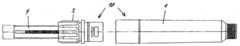
도 1은 제1 실시예에 따른 저장 모듈의 2개의 부분을 나타낸 도면이고;1 shows two parts of a storage module according to the first embodiment;
도 2는 도 1의 2개의 부분으로부터 얻은 저장 모듈을 나타낸 도면이며;2 shows a storage module obtained from the two parts of FIG. 1;
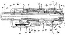
도 3은 제1 실시예에 따른 도 2의 저장 모듈을 구비한 주입 장치의 종단면도이고;3 is a longitudinal sectional view of the injection device with the storage module of FIG. 2 according to the first embodiment;
도 4는 도 3의 주입 장치의 일부를 나타낸 도면이며;4 shows a part of the injection device of FIG. 3;
도 5는 저장 모듈의 기구 홀더의 종단면도 및 정면도이고;5 is a longitudinal sectional view and a front view of the instrument holder of the storage module;
도 6은 기구 홀더에 의해 장착된 피스톤 로드용 저지 수단을 나타낸 도면이며;6 shows a blocking means for a piston rod mounted by an instrument holder;
도 7은 피스톤 로드의 종단면도 및 정면도이고;7 is a longitudinal sectional view and a front view of the piston rod;
도 8은 래칭 수단의 종단면도, 측면도, 및 평면도이며;8 is a longitudinal sectional view, a side view, and a plan view of the latching means;
도 9는 주입 장치의 제2 실시예를 나타낸 도면이고;9 shows a second embodiment of an injection device;
도 10은 도 9의 A-A 선을 따른 횡단면도이며;10 is a cross sectional view along line A-A of FIG. 9;
도 11은 도 9의 B-B 선을 따른 횡단면도이고;FIG. 11 is a cross sectional view along line B-B of FIG. 9;
도 12는 도 9의 C-C 선을 따른 횡단면도이며;12 is a cross sectional view along line C-C in FIG. 9;
도 13은 도 9의 D-D 선을 따른 횡단면도이고;FIG. 13 is a cross sectional view along the line D-D in FIG. 9;
도 14는 제2 실시예의 기구 홀더의 사시도이며;14 is a perspective view of the instrument holder of the second embodiment;
도 15는 도 14의 기구 홀더의 측면도이고;15 is a side view of the instrument holder of FIG. 14;
도 16은 도 15의 A-A 선을 따른 횡단면도이며;FIG. 16 is a cross sectional view along line A-A of FIG. 15;
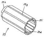
도 17은 제2 실시예의 정량분 세팅 부재의 사시도이고;17 is a perspective view of the quantitative setting member of the second embodiment;
도 18은 도 17의 정량분 세팅 부재의 종단면도이며;18 is a longitudinal cross-sectional view of the metering setting member of FIG. 17;
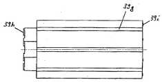
도 19는 도 17의 정량분 세팅 부재의 측면도이고;19 is a side view of the quantitative setting member of FIG. 17;
도 20은 도 17의 정량분 세팅 부재의 평면도이며;20 is a plan view of the quantitative setting member of FIG. 17;
도 21은 도 3에 따른 주입 장치의 일부를 나타낸 도면이고;21 shows a part of the injection device according to FIG. 3;
도 22는 도 9에 따른 주입 장치의 일부를 나타낸 도면이다.22 shows a part of the injection device according to FIG. 9.
도 1은 서로 연결되어 도 2에 도시된 저장 모듈(10)을 형성하는 저장부(1)와 기구 홀더(3)를 나타낸 것이다.FIG. 1 shows the
또한, 도 1 및 도 2에서는 저장부(1)로부터 외면된 기구 홀더(3)의 일단에서 기구 홀더(3) 내로 돌출되는 피스톤 로드(4)를 찾아볼 수 있는데, 그 피스톤 로드(4)는 피스톤 로드(4)의 종 방향 축선(L)을 향한 전진 방향으로 기구 홀더(3)로부터 외면된 저장부(1)의 전단 쪽으로 이동될 수 있도록 기구 홀더(3)에 의해 장착된다. 저장부(1)는 전체적으로 원형 횡단면을 갖고 그 전단에 주입 바늘용 바늘 홀더에 연결하기 위한 연결 구역을 구비한 중공 실린더이다. 저장부(1)는 본 실시예의 경우에 도 3의 종단면도에서 볼 수 있는 앰플(2)에 의해 형성되는 저장 용기를 수납하는 역할을 한다. 앰플(2)의 전단에 있는 출구는 유체가 새지 않게 막에 의해 밀봉된다. 바늘 홀더가 저장부(1)의 전단에 고정되면, 주입 바늘의 후방부가 막을 뚫어 중공 주입 바늘의 선단과 저장부(2) 사이에 유체 접속이 이뤄지게 된다.1 and 2, a
도 3은 주입 장치의 전체를 종단면도로 나타낸 것이다. 앰플(2) 내에는 피스톤이 그 앰플(2)의 전단에 형성된 출구를 향해 전진 방향으로 이동될 수 있도록 수납된다. 피스톤을 전진 방향으로 이동시킴으로써, 물질이 앰플(2)로부터 배출되어 출구 및 주입 바늘을 통해 급송되게 된다.3 is a longitudinal sectional view of the entire injection device. In the ampoule 2, the piston is housed so as to be able to move in a forward direction toward an outlet formed at the front end of the ampoule 2. By moving the piston in the forward direction, material is withdrawn from the ampoule 2 and fed through the outlet and the injection needle.
피스톤은 그 전단을 매개로 하여 피스톤을 밀쳐서 그 자체의 전진 시에 피스톤을 전진 방향으로 이동시키는 피스톤 로드(4)에 전진된다. 피스톤 로드(4)는 일단 일정한 저항을 넘어서고 난 후에 전진 방향으로 이동될 수 있지만 전진 방향의 반대 방향으로는 이동될 수 없도록 기구 홀더(3)에 의해 유지된다. 저지 수단(8)은 피스톤 로드(4)가 전진 방향의 반대 방향으로 되돌아 이동되는 것을 저지한다. 그러한 저지 수단(8)은 축 방향으로 기구 홀더(3)에 의해 고정된다. 즉, 전진 방향과 그 반대 방향으로 이동될 수 없도록 기구 홀더(3) 내에 유지된다. 그러나, 저지 수단(8)은 종 방향 축선(L)을 중심으로 하여 회전될 수 있도록 기구 홀더(3)에 의해 장착된다. 저지 수단(8)은 전진 이동을 위해 넘어서야 하는 저항을 일으키기도 한다.The piston is advanced to the
저지 수단(8) 그 자체는 도 6에 도시되어 있다. 그러한 저지 수단(8)은 일체형 환형 요소에 의해 형성되고, 그 환형 요소는 종 방향 축선(L)을 중심으로 하여 회전될 수 있게 2개의 대면된 이격 칼라(3b) 사이에서 기구 홀더(3)와 접하는데, 그 경우에 이격 칼라(3b)는 기구 홀더(3)의 내면으로부터 반경 방향의 안쪽으로 돌출된다. 그러한 칼라(3b)는 축 방향으로 저지 수단(8)을 고정시키기 위한 고정 수단을 형성한다. 도 5에 기구 홀더(3)를 나타낸 것으로부터 저지 수단(8)이 기구 홀더(3)에 어떻게 장착되는지를 가장 명확히 알 수 있다.The impeding means 8 itself is shown in FIG. 6. Such restraining means 8 are formed by an integral annular element, the annular element being between the
또한, 기구 홀더(3) 내에는 정량분 세팅 부재(9)가 수납된다. 그러한 정량분 세팅 부재(9)는 나사 너트로서 형성되어 피스톤 로드(4)의 수나사에 나사 결합으로 맞물린다. 정량분 세팅 부재(9)는 기구 홀더(3)에 의해 회전되지 않게 고정되지만, 전진 방향과 그 반대 방향으로 축 방향을 따라 선형 이동될 수 있도록 안내된다. 피스톤 로드(4)와 정량분 세팅 부재(9)는 투여하려는 물질 정량분을 선택하기 위한 스핀들을 형성한다.In addition, the
앰플 홀더(1)와 기구 홀더(3)는 서로 연결되어 회전 및 이동되지 않게 고정되어 함께 주입 장치의 저장 모듈(10)을 형성하는데, 그러한 저장 모듈(10)은 저지 수단(8)에 의해 기구 홀더(3)에 유지되는 피스톤 로드(4)와 정량분 세팅 부재(9)를 구비한다. 앰플 홀더(1)와 기구 홀더(3)는 함께 주입 장치의 전방 케이싱 섹션을 형성한다. 전방 케이싱 섹션(1, 3)에는 후방 케이싱 섹션(11)이 누름 잠김(positive lock)식으로 연결된다. 후방 케이싱 섹션(11)은 정량 및 작동 요소(12)의 지지체를 형성하고, 정량 및 작동 요소(12), 래칭 수단의 부품, 및 기타의 부품과 함께 주입 장치의 정량 및 작동 모듈(30)을 형성한다.The
정량 및 작동 장치는 정량분 세팅 부재(9), 피스톤 로드(4), 및 저지 수단(8) 이외에, 물질 정량분을 선택하고 주입 장치를 작동시키기 위한 다른 부품을 구비한다. 특히, 정량 및 작동 장치는 정량 및 작동 요소(12)를 구비한다. 정량 및 작동 장치는 선택된 물질 정량분을 계수하고 시각적으로 지시하기 위한 계수 및 지시 수단(17)을 추가로 구비한다. 특히, 그러한 계수 및 지시 수단(17)은 정량 및 작동 장치가 주입 장치의 고급 부품, 그에 따라 값비싼 부품이 되도록 만든다. 비교적 저렴한 저장 모듈(10)은 일회용 모듈로서 설계된 것인데 반해, 정량 및 작동 모듈(30)은 일관되게 새로운 저장 모듈(10)과 함께 반복적으로 사용하려고 의도된 것이다.The metering and actuating device has, in addition to the
물질 정량분을 선택하기 위해, 즉 정량하기 위해, 정량 및 작동 요소(12)는 종 방향 축선(L)을 중심으로 하여 회전될 수 있고, 아울러 전진 방향과 그 반대 방향으로 종 방향 축선(L)을 따라 선형 이동될 수 있도록 후방 케이싱 섹션(11)에 의 해 장착된다. 정량 및 작동 요소(12)는 중공 원통형이고, 전방 섹션에 의해 피스톤 로드(4)를 둘러싼다. 정량 및 작동 요소(12)의 후방 섹션은 케이싱 섹션(11)의 후단으로부터 그를 넘어 돌출된다. 정량 및 작동 요소(12) 내에는 반경 방향의 안쪽으로 돌출된 정량 및 작동 요소(12)의 칼라까지 후방으로부터 로드형 정량 종속 장치 수단(dosing slaving means)(13)이 삽입된다. 또한, 후단에서는 정량 종속 장치 수단(13)까지 마개(14)가 정량 및 작동 요소(12) 내에 삽입된다. 정량 종속 장치 수단(13)은 반경 방향으로 돌출된 정량 및 작동 요소(12)의 칼라와 마개(14) 사이에서 정량 및 작동 요소(12)에 대해 축 방향으로 고정된다. 또한, 정량 종속 장치 수단(13)은 회전되지 않게 고정된 채로 정량 및 작동 요소(12)에 연결된다. 정량을 위해, 정량 종속 장치 수단(13)이 후방으로부터 중공 피스톤 로드(4) 내로 돌출된다. 피스톤 로드(4)는 정량 종속 장치 수단(13)에 맞물리는 연결 섹션(4a)(도 4)을 구비하여 피스톤 로드(4)와 정량 종속 장치 수단(13)이, 그에 따라 정량 및 작동 요소(12)가 공통의 종 방향 축선(L)을 중심으로 하여 서로에 대해 회전될 수 없게 되지만, 전진 방향과 그 반대 방향으로 종 방향 축선(L)을 따라 서로에 대해 이동될 수는 있다. 그를 위해, 연결 섹션(4a)은 정량 종속 장치 수단(13)용 선형 가이드로서 형성된다.In order to select, ie to quantify, the quantity of mass, the quantitative and actuating
복원 수단(16)은 전진 방향의 반대 방향으로 정량 및 작동 요소(12)를 도 3 및 도 4에 도시된 초기 위치로 잡아당긴다. 그러한 초기 위치에서는 정량 및 작동 요소(12)를 종 방향 축선(L)을 중심으로 하여 회전시킴으로써 물질이 정량될 수 있다. 이어서, 정량 및 작동 요소(12)를 축 방향으로 이동시킴으로써, 선택된 물질 정량분이 초기 위치로부터 급송될 수 있다. 복원 수단(16)은 압축 스프링으로서 작용하는 코일 스프링에 의해 형성되는데, 그 코일 스프링은 정량 및 작동 요소(12)의 둘레에 있는 환형 갭에 수납되고, 반경 방향의 안쪽으로 돌출된 케이싱 섹션(11)의 칼라와 반대쪽을 향해 반경 방향의 바깥쪽으로 돌출된 정량 및 작동 요소(12)의 칼라 사이에 축 방향으로 지지된다.Restoration means 16 pull the metering and operating
저지 수단(8)은 이중의 기능을 이행한다. 한편으로, 저지 수단(8)은 그 저지 요소(8a)에 의해 피스톤 로드(4)가 전진 방향의 반대 방향으로 기구 홀더(3)에 대해, 그에 따라 특히 앰플(2)에 수납된 피스톤에 대해 뒤로 이동될 수 없도록 하는 것을 보장한다. 아울러, 저지 수단(8)은 제동기로서의 그 이중 기능 시에는 정량분 세팅 부재(9)가 전진 방향의 반대 방향으로 축 방향을 따라 정량 및 작동 요소(12) 쪽으로 이동되는 정량 과정 동안 피스톤 로드(4)가 전진 이동되는 것을 저지한다.The impeding means 8 fulfills a dual function. On the one hand, the impeding
도 3 및 도 4에 도시된 정량 전의 초기 위치에서는 정량분 세팅 부재(9)가 기구 홀더(3)에 의해 형성된 급송 스토퍼(3c)(도 5)에 맞대어 전진 방향으로 접한다. 피스톤 로드(4)는 피스톤과 영구적으로 접촉된다. 정량을 위해, 정량 세팅 부재(9)는 피스톤 로드(4)와 나사 결합으로 맞물리고 기구 홀더(3)로부터 선형 안내됨으로써 급송 스토퍼(3c)로부터 떨어져 이동된다. 그럼으로써, 정량분 세팅 부재(9)의 후방 스토퍼 구역과 정량 및 작동 요소(12)의 전방 스토퍼 구역 사이와 미세 간격이 줄어들지만, 다른 한편으로 정량분 세팅 부재(9)의 전방 스토퍼 구역과 급송 스토퍼(3c) 사이의 미세 간격이 커지게 된다. 급송 스토퍼(3c)와 정량분 세팅 부재(9) 사이의 후자의 간격은 정량 및 작동 요소(12)의 급송 이동 동안 정량 분 세팅 부재(9)가, 그리고 나사 결합 맞물림으로 인해 피스톤 로드(4)가 전진 방향으로 이동되는 만큼의 경로 길이이다. 급송 스토퍼(3c)는 전방 병진 스토퍼를 형성한다. 급송 이동 동안, 피스톤 로드(4)는 피스톤 로드(4)가 전진 방향이든 그 반대 방향이든 이동될 수 없도록 피스톤 로드(4)에 연결된 플런저 본체에 의해 형성되는 그 전단을 매개로 하여 피스톤을 밀침으로써 피스톤을 전진 방향으로 앰플(2)의 출구 쪽으로 밀어낸다. 종 방향 축선(L)은 물질을 정량하고 급송하려고 행해지는 이동의 회전 축선 및 병진 축선을 형성한다.In the initial position before the metering shown in FIGS. 3 and 4, the
정량분 세팅 부재(9)가 급송 스토퍼(3c)에 맞대어 접할 경우에 정량 과정 동안 정량분 세팅 부재(9)와 정량 및 작동 요소(12)가 상호간에 나타내는 간격은 선택되어 급송 과정 중에 급송될 수 있는 최대 물질 정량분에 해당된다. 정량 및 작동 요소(12)의 행정 이동은 각각의 급송에 있어 동일한 길이로 된다. 정량은 정량분 세팅 부재(9)와 급송 스토퍼(3c) 사이의 간격을, 그리고 그에 따라 급송 과정 중에 정량 및 작동 요소(12)와 정량분 세팅 부재(9)에 의해 함께 이동될 수 있는 경로 길이만을 세팅할 따름이다.When the
도 6 및 도 7을 살펴보면, 저지 수단(8)의 제동 기능 및 그를 위해 피스톤 로드(4)와 저지 수단(8) 사이에 존재하는 제동 맞물림을 명확히 알 수 있다. 다른 한편으로, 저지 수단(8)은 제동 맞물림을 위한 2개의 제동 요소(8b)를 구비하는데, 그 2개의 제동 요소(8b)는 그 앞에 있는 저지 수단(8)과 유사하게 탄성적으로 굽혀질 수 있는 캐치(catch)에 의해 각각 형성된다. 본 실시예에서는 저지 수단(8)이 접경 측에서 그로부터 4개의 탄성 캐치가 축 방향으로 돌출되는 단일의 환형 요소 에 의해 형성된다. 캐치는 환형 요소의 둘레에 걸쳐 균일한 분포로 배치된다. 서로 대향된 2개의 캐치는 저지 요소(8a)를 형성하고, 마찬가지로 서로 대향된 다른 2개의 캐치는 제동 요소(8b)를 형성한다.6 and 7, it can be clearly seen that the braking function of the blocking means 8 and the braking engagement present therefor between the
따라서, 피스톤 로드(4)는 대향 측에서 외면 상에 형성되어 피스톤 로드(4)의 종 방향으로 연장되는 2개의 복귀 저지 수단(6)과 마찬가지로 서로 대향된 측에서 피스톤 로드(4)의 종 방향으로 연장되는 2개의 전진 제동 수단(7)을 구비하게 된다. 정량분 세팅 부재(9)에 나사 결합으로 맞물리기 위한 피스톤 로드(4)의 나사는 피스톤 로드(4)의 거의 전체의 길이에 걸쳐 연장되는 4개의 잔여 나사 섹션에 의해 형성된다. 복귀 저지 수단(6)과 전진 제동 수단(7)은 이빨 열에 의해 각각 형성된다. 그러나, 복귀 저지 수단(6)의 이빨은 전진 방향으로 좁혀지고 후방을 향한 저지 구역을 구비하며 전진 방향을 가로질러 연장되는 톱니로서 형성되는 반면에, 전진 제동 수단(7)을 형성하는 2열의 이빨은 필적할만한 효과를 갖는 전방으로 향한 저지 구역을 구비하지 않는다. 전진 제동 수단(7)의 이빨은 복귀 저지 수단(6)에 비해 더 원활한 이빨 프로파일을 각각 나타낸다. 피스톤 로드(4)의 저지 수단(8)과 전진 제동 수단(7) 사이의 제동 맞물림은 피스톤 로드(4)가 전진하는 것을 저지하려고 의도된 것이 아니라, 단지 그것을 좀더 어렵게 만들어 피스톤 로드(4)가 정량 동안 전진 방향을 이동되지 못하는 것을 보장하려고 의도된 것이다. 전진 제동 수단(7)의 이빨의 전방 측은 제동 맞물림을 극복하기 위해서는 정량 동안 도달되지 않는 임계의 힘을 넘어서야 하도록 형성된다. 그러한 임계의 힘은 저지 수단(8a) 상에서 복귀 저지 수단(6)의 이빨을 전진 방향으로 이동시키는데 필 요한 힘보다 더 크다. 그러한 임계의 힘은 복귀 저지 수단(6)과 저지 수단(8a) 사이의 초기 마찰력의 2배 이상인 것이 바람직하다. 후자간의 마찰력도 역시 전진 이동 과정 중에 2개의 연속된 저지 맞물림 사이에서 점진적으로만 증가될 뿐이다. 그 반면에, 제동 맞물림의 임계의 힘은 전지 이동이 시작되자마자 각각의 저지 맞물림에서 하나의 저지 맞물림으로부터 다음 저지 맞물림으로 인가되어야 한다. 그러나, 그러한 임계의 힘은 급송 동안 사용자를 곤혹스럽게 할 정도로 커서는 안 된다.Accordingly, the
저지 수단(8)의 저지 맞물림에만 의한다면, 원칙적으로 정량분을 선택할 때에 정량분 세팅 부재(9)에 의한 이동에 응하여 피스톤 로드에 의한 원하지 않는 이동이 일어날 수도 있다. 그러나, 그러한 이동은 제동 맞물림으로 인해 저지 맞물림에만 의하는 것보다 더 확실하게 저지되게 된다.If only by the interlocking engagement of the impeding
저장 모듈(10)과 정량 및 작동 모듈(30) 사이의 연결은 누름 잠금(positive lock)이다. 다른 한편으로, 기구 홀더(3)와 케이싱 섹션(11) 사이에는 축 방향으로의 상대 이동을 저지하는 래칭 맞물림이 존재한다. 그러한 래칭 맞물림 이외에는, 전방 케이싱 섹션(1, 3)과 후방 케이싱 섹션(11)이 축 방향으로 직접 서로 상으로 선형 안내되어 연결 시의 상대 회전이 저지되도록 한다. 도 5에서는 후방 케이싱 섹션(11)의 하나 이상의 해당 맞물림 요소와 함께 선형 가이드를 형성하는 기구 홀더(3)의 축 방향 가이드(3d)를 명확히 알아볼 수 있다. 그러한 축 방향 가이드(3d)는 가이드 리브 상에 있는 가이드 구역에 의해 형성된다; 그러한 축 방향 가이드(3d)는 축 방향으로 연장된 리세스 내에 있는 가이드 구역에 의해 형성될 수도 있다. 그와 같이 하여, 축 방향가이드 채널이 얻어진다. 가이드 리브는 축 방향 으로 테이퍼져서 가이드 채널 내로 인도되는 삽입 깔때기가 후방 케이싱 섹션(11)의 하나 이상의 맞물림 요소에 대해 형성되게 된다. 연결을 시작할 때에 케이싱 섹션(1, 3, 11)을 훨씬 잘 센터링시키기 위해, 가이드 리브는 반경 방향으로도 테이퍼진다. 후방 케이싱 섹션(11)의 하나 이상의 맞물림 요소는 축 방향 섹션(3d)과 마찬가지로 후방 케이싱 섹션(11)의 표면 반대 구역, 즉 내면 구역 상에 형성되는 것이 바람직하다.The connection between the
래칭 맞물림은 기구 홀더(3)의 제1 암 래칭 요소(3a)(도 5)와 후방 케이싱 섹션(11)에 연결된 래칭 링(20) 사이에 존재하여 후방 케이싱 섹션(11)이 반경 방향으로 이동될 수 있지만 축 방향으로는 이동될 수 없게 된다. 래칭 링(20)은 반경 방향으로 제1 래칭 요소(3a)에 직접 맞물리는 제2 수 래칭 요소(21)를 형성한다. 제1 래칭 요소(3a)와 제2 래칭 요소(21) 사이에는 저장 모듈(10)과 정량 및 작동 모듈(30)이 축 방향으로 서로에 대해 이동되는 것을 저지하는 로크/래치 연결이 존재한다.A latching engagement exists between the first
도 3 및 도 4는 래칭을 위해 래칭 요소(3a)에 맞물린 래칭 요소(21)를 나타낸 것이다. 래칭 요소(3a)는 환형 스테이(stay)와 기구 홀더(3)의 외면 둘레에 연장된 홈에 의해 형성된다. 환형 스테이는 홈의 후방 측벽을 형성한다. 제2 래칭 요소(21)는 래칭 링(20)의 내면으로부터 반경 방향의 안쪽으로 돌출된 캠에 의해 형성되는데, 그 캠은 래칭 맞물림 시에 복원 수단(24)에 의해 수납 래칭 요소(3a) 내로 돌출된 후방 케이싱 섹션(11)의 내면 상으로 반경 방향의 안쪽으로 밀어내어진다. 래칭 링(20)은 전체적으로 후방 케이싱 섹션(11)에 의해 형성된 내면 구역 상 에서 반경 방향으로 복원 수단(24)에 의해 지지되고, 그에 따라 복원 수단(24)이 대략 래칭 요소(21)의 반경 방향 연장선에서 래칭 링(20)의 외면을 밀치게 된다. 래칭 링(20)은 기구 홀더(3)를 둘러싸고, 반경 방향으로 복원 수단(24)의 복원력을 거슬러 전후로 이동될 수 있어 제2 래칭 요소(21)가 래칭을 위해 제1 래칭 요소(3a)에 맞물리도록, 그리고 그 래칭 맞물림으로부터 벗어나도록 이동될 수 있게 된다. 후방 케이싱 섹션(11)은 래칭 링(20)의 반경 방향 이동을 위한 억지 슬라이딩 가이드(tight sliding guide)를 형성한다. 래칭 링(20)은 반경 방향으로 래칭 요소(21)와 대향된 측에서 사용자용 래칭 해제 버튼(unlatching button)(22)을 형성한다. 압축 스프링으로서 형성된 복원 수단(24)을 반경 방향으로 안내하기 위해, 가이드 캠은 래칭 요소(21)로부터 외면된 래칭 링(20)의 외면 구역으로부터 반경 방향으로 돌출된다.3 and 4 show the latching
아울러, 래칭 블록(25)에 맞대어 그를 반경 방향의 안쪽으로 누르는 2개의 저지 캠(23)은 그 가이드 캠의 양측에서 래칭 링(20)의 외면 구역으로부터 원주 방향으로 돌출되고, 가이드 캠의 배후에서 축 방향으로 돌출된다. 저지 캠(23)은 래칭 블록(25)에 맞대어 접하기 때문에, 래칭 요소(21)의 반경 방향 이동(래칭 맞물림의 해제를 가져올 수 있음)이 저지되게 된다. 따라서, 래칭 요소(3a)와 래칭 요소(21) 사이의 래칭 맞물림이 래칭 블록(25)에 의해 고정된다. 래칭 맞물림은 정량 및 작동 요소(12)가 그 급송 이동의 종료 시에 취하는 해제 위치를 제외하고는 정량 및 작동 요소(12)의 모든 위치에서 고정된다. 따라서, 해제 위치는 정량 및 작동 요소(12)가 그 급송 이동 과정 중에 정량분 세팅 부재(9)에 접하고 정량분 세팅 부재(9) 자체가 기구 홀더(3)의 급송 스토퍼(3c)에 맞대어 접할 때에 정량 및 작동 요소(12)가 취하는 최전방 이동 위치와 일치한다. 정량 및 작동 모듈(30)이 아직 저장 모듈(10)에 연결되지 않았다면, 정량 및 작동 요소(12)를 위한 기계적 스토퍼는 정량 및 작동 장치의 스토퍼 요소에 의해 형성된다. 본 실시예에서는 지시계(17)를 리셋하는 역할을 하는 리셋 홀더 링이 스토퍼 요소(31)를 형성한다. 그 경우, 스토퍼 요소(31)에 맞대어 접하는 정량 및 작동 요소(12)가 그 정량 및 작동 요소(12)의 해제 위치를 규정짓는데, 그 해제 위치는 급송 스토퍼(3c)에 접하는 정량분 세팅 부재(9)에 의해 규정지어진 해제 위치에 대응하여 스토퍼 요소(31)에 의해 규정지어진다.In addition, the two
도 8은 래칭 블록(25)을 나타낸 것이다. 본 실시예에서는 래칭 블록(25)이 저지 슬라이더에 의해 일체로 형성된다. 래칭 블록(25)은 예컨대 도 4에 도시된 바와 같이 조립 시에 축 방향으로 연장되는 판형 본체를 구비한다. 일단에서는 스테이(26)가 본체로부터 직각으로 돌출된다. 조립 시에, 스테이(26)는 반경 방향으로 정량 및 작동 요소(12)까지 연장된다. 스테이(26)는 래칭 블록(25)을 정량 및 작동 요소(12)에 고정시키는 역할을 하는데, 그를 위해 정량 및 작동 요소(12)는 외면 구역 상에 축 방향으로 이격되어 형성된 2개의 환형 스테이를 구비하고, 그 2개의 환형 스테이는 종속 장치 수단(15a, 15b)을 형성한다. 그와 동시에, 전방 종속 장치 수단(15a)은 복원 수단(16)용 지지 칼라를 형성한다. 종속 장치 수단(15a, 15b) 사이에 형성되는 환형 공간 내로는 래칭 블록(25)이 그 스테이(26)를 매개로 하여 돌출되어 축 방향으로 양측에서 2개의 종속 장치 수단(15a, 15b)에 의해 꼭 끼게 둘러싸인다.8 shows the latching
래칭 블록(25)의 본체는 스테이(26)로부터 외면된 전단에 래칭 블록(25)의 전단 쪽으로 개방된 축 방향 리세스(27)를 구비한다. 그와 같이 하여, 리세스(27)의 양측에서 축 방향으로 연장되는 저지 텅(blocking tongue)(28)이 형성되게 된다. 래칭 링(20)의 저지 캠(23)은 정량 및 작동 요소(12)가 해제 위치를 취하고 있지 않음을 전제로 하여 각각의 저지 캠(23)이 래칭 텅(28)을 밀치도록 배치된다. 래칭 블록(25)이 축 방향으로 이동될 때에는 래칭 요소(21)의 복원 수단(24)이 축 방향 리세스(27)를 통해 연장된다.The main body of the latching
또한, 래칭 블록(25)의 본체에는 노치 리세스(29)가 형성되어 정량 및 직동 요소(12)의 해제 위치를 규정짓는다. 각각의 저지 캠(23)에 대해 하나의 노치 리세스(29)가 제공된다. 노치 리세스(29)의 위치는 정량 및 작동 요소(12)가 그 해제 위치로 전진되었을 때에 저지 캠(23)과 겹쳐지기만 하여 저지 캠(23)이 삽입될 수 있게끔 하도록 선택된다.In addition, a
본 실시예에서 특정적으로 선택된 배치에서는 단일의 저지 캠(23)이 마련되어 래칭 블록(25)이 단 하나의 노치 리세스(29) 및 가능하다면 역시 단 하나의 저지 텅(28)만을 구비할 수도 있음이 명백하다. 또한, 래칭 블록은 원칙적으로 정량 및 작동 요소(12)와 함께 일체로 제조된다. 그러나, 그것을 별개의 부품으로서 형성하는 것이 제조, 조립, 및 피스톤 로드(4)와 연동하는 정량 및 작동 요소(12)와 관련된 장점을 제공해 준다. 래칭 블록(25)의 설치 길이와 관련하여, 래칭 블록(25)이 래칭 요소(21)로부터 외면된 그 외측에서 케이싱(11)의 내면 구역 상에 지지된다는 점이 아울러 지적되어야 한다. 그와 같이 하여, 래칭 맞물림을 고정시키는 안정성이 증대되게 된다. 케이싱(11)은 래칭 블록(25)의 축 방향 가이드를 형성하는 것이 바람직하다.In a particular selected arrangement in this embodiment a
이후로는 주입 장치의 기능 형식에 관해 설명하기로 하는데, 그러한 설명에서는 새로운 저장 모듈(10)과 이미 한 번 이상 사용된 정량 및 작동 모듈(30)이 조립되고 나서 물질이 처음으로 급송된다고 가정하기로 한다.The functional form of the injection device will now be described, which assumes that the material is first delivered after the
정량 및 작동 모듈(30)과 새로운 저장 모듈(10)은 그것의 2개의 종 방향 축선이 서로 일렬로 놓이도록 서로에 대해 정렬된다. 이어서, 저장 모듈(10)이 전방으로 개방된 정량 및 작동 모듈(30)의 케이싱(11) 내로 그 후단을 매개로 하여 삽입된다.The quantification and
그럼으로써, 케이싱 섹션(1, 3)과 케이싱 섹션(11)이 기구 홀더(3)의 가이드 리브(3d)의 테이퍼진 단부에 센터링되게 된다. 2개의 케이싱 섹션은 슬라이딩되는 동안 선형 가이드에 의해 미리 세팅된 회전 각 위치로 축 방향을 따라 서로 상으로 선형 안내되어 궁극적으로 케이싱 섹션(1, 3, 11)이 래칭 요소(3a, 21)의 래칭 맞물림이 이뤄질 수 있거나 자력으로 설정될 수 있게 하는 연결 위치를 차지하게 된다.The
적량 및 작동 요소(12)는 후방 케이싱 섹션(11)에 대해 미리 세팅된 회전 각 위치로 로킹된다. 케이싱 섹션(1, 3, 11)의 선형 가이드와 정량 및 작동 요소(12)의 회전 각 로킹 위치는 정량 및 작동 요소(12)의 모든 로킹 위치 및 케이싱 섹션(1, 3, 11)이 서로 상으로 선형 안내되는 모든 회전 각 위치에서 정량 및 작동 요소(12)와 피스톤 로드(4) 사이에 회전되지 않게 고정된 맞물림이 이뤄지도록 서로 조정된다.The dose and
정량 및 작동 요소(12)가 케이싱 섹션(11)에 대해 해제 위치의 배후에 있는 축 방향 위치에 위치되면, 래칭 요소(21)는 래칭 블록(25)에 의해 반경 방향의 그 가장 안쪽 위치에 유지된다. 래칭 요소(21)의 그러한 위치에서는 정량 및 작동 모듈(30)과 저장 모듈(10)이 연결 단부 위치까지 서로 상으로 슬라이딩될 수 없으므로, 서로 연결될 수도 없는데, 그것은 제1 래칭 요소(3a)의 일부를 형성하는 기구 홀더(3)의 외면 상에 형성된 환형 스테이가 먼저 제2 래칭 요소(21)에 맞대어 접한 채로 정지되어 있기 때문이다.If the metering and actuating
환형 스테이는 접선 방향으로 짧은 반경 방향 돌출부로 감축될 수 있는데, 그것은 그 돌출부와 제2 래칭 요소(21)가 축 방향으로 일렬로 정지되는 회전 각 위치로만 케이싱 섹션(1, 3, 11)이 조립될 수 있다는 것이 보장된 한에서 그러하다. 환형 스테이 또는 반경 방향 돌출부는 제1 래칭 요소(3a)만을 형성할 수도 있는데, 왜냐하면 제1 래칭 요소(3a)의 주된 기능은 정량 및 작동 요소(12)가 그 해제 위치를 취할 때에만 저장 모듈(10)과 정량 및 작동 모듈(30) 사이의 연결이 이뤄질 수 있도록 하는 것이기 때문이다. 그러한 조건이 충족된다면, 정량 및 작동 요소(12)는 저장 모듈(10)과 정량 및 작동 모듈(30) 사이의 연결이 이뤄질 때에 정량분 세팅 부재(9)가 기구 홀더(3)의 급송 스토퍼(3c)에 접하는 정량 지로 위치에 위치되도록 하는 것을 보장하게 된다.The annular stay can be reduced in a tangential direction into a short radial projection, in which the
전술된 조건을 충족시키기 위해, 사용자는 정량 및 작동 요소(12)를 축 방향 을 따라 후방 케이싱 섹션(11)에 대해 전방으로 해제 위치까지 밀어낸다. 후방 케이싱 섹션(11)과 정량 및 작동 요소(12) 사이의 그러한 상대 위치에서는 저지 캠(23)이 래칭 블록(25)의 노치 리세스(29) 내로 이동될 수 있게 된다. 따라서, 사용자는 정량 및 작동 요소(12)를 적어도 해제 위치까지 밀어낼 뿐만 아니라, 동시에 래칭 해제 버튼에 의해 제1 래칭 요소(20)를 래칭 맞물림으로부터 벗어나도록 밀어낸다. 이어서, 저장 모듈(10)이 축 방향으로 제1 래칭 수단(3a)의 환형 스테이 상으로 이동되어 후방 케이싱 섹션(11) 내로 추가로 삽입될 수 있게 된다. 사용자는 래칭 해제 버튼을 놓을 수 있다. 제1 래칭 요소(21)는 제2 래칭 요소(3a)와 겹쳐지는 즉시로 복원 수단(24)의 힘에 의해 수납 래칭 요소(3a) 내에 스냅-인(snap-in)되어 래칭 맞물림이 이뤄지게 된다. 이어서, 저장 모듈(10)과 정량 및 작동 모듈(30)이 정량분 세팅 요소(9)와 피스톤 로드(4)와 관련하여 정해진 형식으로 서로 연결된다. 래칭 맞물림이 이뤄지기 전에 정량분 세팅 부재(9)가 여전히 급송 스토퍼(3c)로부터 미세 간격을 나타낸다면, 그러한 간격은 연결을 이루는데 요구되는 정량 및 작동 요소(12)의 동작으로 인해 제거되게 된다. 물질의 합성적 급송이 용인될 수 있고, 주입 바늘을 달기 위해서는 심지어 바람직하기까지 하다. 그에 의해, 바람직하게도 계수 및 지시 수단(17)이 0으로 리셋되게 된다.In order to meet the conditions described above, the user pushes the metering and actuating
그와 같이 하여 일어난 규정된 초기 상태에서는 사용자가 물질을 정량할 수 있다. 물질은 정량 및 작동 요소(12)를 종 방향 축선(L)을 중심으로 하여 케이싱 섹션(11)에 대해 회전시킴으로써 정량된다. 정량 종속 장치 수단(13)은 회전되지 않게 고정된 정량 및 작동 요소(12)에 연결되고, 정량 및 작동 요소(12) 그 자체는 회전되지 않게 고정된 피스톤 로드(4)에 맞물리기 때문에, 정량 및 작동 요소(12)는 그 회전 정량 이동 동안 피스톤 로드(4)를 종속 작동시킨다. 피스톤 로드(4)와 정량분 세팅 부재(9) 사이에 나사 결합 맞물림이 이뤄지고, 정량분 세팅 부재(9)가 기구 홀더(3)에 의해 선형으로 안내되기 때문에, 정량분 세팅 부재(9)는 정량 및 작동 요소(12) 쪽으로 왕복 나사 결합 맞물림의 나사 피치에 의해 미리 세팅된 축 방향의 병진 정량 이동을 행한다. 정량 및 작동 요소(12)는 정량분 세팅 부재(9)의 병진 정량 이동을 제한하여 세팅될 수 있는 최대 급송 행정을 한정하는 후방 병진 스토퍼(12c)를 형성한다.In the prescribed initial state so produced, the user can quantify the substance. The material is quantified by rotating the metering and actuating
계수 및 지시 수단(17)은 정량 및 작동 요소(12)의 회전 각 위치에 대응된 정량 단위를 세어서 그것을 시각적으로 지시한다.The counting and indicating means 17 counts the quantity unit corresponding to the angular position of rotation of the metering and operating
일단 원하는 물질 정량분이 선택되고 나면, 정량 과정이 완료된다. 선택된 물질 정량분은 피스톤의 전진 방향을 향한 정량 및 작동 요소(12)의 급송 이동에 의해 급송된다. 그러한 급송 이동 과정 중에는 정량 및 작동 요소(12)가 정량분 세팅 부재(9)에 맞대어 접하여 그것을 종속 작동시킨다. 정량분 세팅 부재(9)가 급송 이동 과정 중에 기구 홀더(3)의 급송 스토퍼(3c)에 맞대어 접할 때에 정량 및 작동 요소(12)의 급송 이동 및 물질의 급송이 완료된다. 일단 사용자가 정량 및 작동 요소(12)를 해제시키고 나면, 정량 및 작동 요소(12)는 복원 수단(16)에 의해 전진 방향의 반대 방향으로 물질을 다시 정량 및 급송하기 위한 새로운 위치로 다시 이동되는 것이 바람직하다. 계수 및 지시 수단(17)은 그러는 중에 0으로 다시 리셋되도록 정량 및 작동 요소(12)에 커플링되는 것이 바람직하다. 계수 및 지시 수단(17)은 이미 급송된 물질의 총량 및 그에 따라 앰플(2) 내에 남겨진 물질의 잔량을 계수하여 지시하는 수단을 구비할 수도 있다.Once the desired material dose has been selected, the quantification process is complete. The selected mass of material is fed by the metering towards the forward direction of the piston and by the feeding movement of the operating
저장 모듈(10)을 정량 및 작동 모듈(30)로부터 분리시키기 위해, 정량 및 작동 요소(12)는 해제 위치까지, 즉 그것이 정량분 세팅 부재(9)에 맞대어 접할 때까지 전진된다. 그러한 위치에서는 사용자가 래칭 해제 버튼(22)을 누름으로써 래칭 맞물림을 다시 해제시켜 저장 모듈(10)을 정량 및 작동 모듈(30)로부터 분리시킬 수 있게 된다.In order to separate the
도 9 내지 도 13에는 본 발명의 제2 실시예에 따른 주입 장치의 종단면도 및 4개의 횡단면도가 도시되어 있다. 본 발명의 제2 실시예에 따른 주입 장치의 래치 및 래칭 블록은 본 발명의 제1 실시예에 따른 주입 장치의 래치 및 래칭 블록(25)과 유사한 구조를 갖고 있으며, 따라서 이에 대한 설명은 제1 실시예를 참조하기로 한다. 특히, 본 발명의 제2 실시예에 따른 래칭 블록(25)의 전체적인 기능면에서 본 발명의 제1 실시예에 따른 래칭 블록과 동일하다. 래칭 부재들 (3a, 21) 또한 동일한 기능을 가지고 있다.9 to 13 show a longitudinal section and four cross-sectional views of an injection device according to a second embodiment of the invention. The latch and latching block of the injection device according to the second embodiment of the present invention has a structure similar to that of the latch and latching
도 10 내지 도 12는 주입 장치가 초기 상태일 때 상기 래칭 링(20) 그리고 래칭 부재(21)와 래칭 블록(25)에 대한 저지 캠(29)들의 위치를 명확하게 보여주는 횡단면도로서, 본 발명의 제1 실시예를 보여주고 있다.10 to 12 are cross-sectional views that clearly show the position of the latching
본 발명의 제2 실시예에 따른 주입 장치는 정량에 포함된 요소들의 이동 및 로킹의 견지에서 제1 실시예와는 다르다. 또한, 본 발명의 제2 실시예에 따른 기구 홀더는 본 발명의 제1 실시예에 따른 기구 홀더의 기능은 물론이고, 정량분 세팅 부재를 기구 홀더에 대해 가변되는 별도의 회전 각 위치에 정량을 목적으로 배치시킬 수 있는 기능을 갖고 있다. 본 발명의 제2 실시예에 따른 저지 수단은 본 발명의 제1 실시예에 따른 저지 수단에 비해 보다 단순화된 형태로 구현된다. 일차적으로, 본 발명의 제2 실시예에 따른 저지 수단과 본 발명의 제1 실시예에 따른 저지 수단의 차이점이 이하 설명될 것이다. 본 발명의 제2 실시예를 설명함에 있어서, 본 발명의 제1 실시예에 따른 구성 요소와 동일한 명칭 및 기본 기능을 갖고 있으나 그 상세 기능이 다른 요소들에 대해서는 끝 단위를 동일하게 하여 30번 대의 도면 부호를 기재하거나 또는 동일한 도면 부호를 부가하였다. 본 발명의 제2 실시예와 관련하여 특별히 언급되지 않은 사항은 본 발명의 제1 실시예에서 언급된 내용에 준하는 것으로 간주한다.The injection device according to the second embodiment of the present invention differs from the first embodiment in terms of the movement and locking of the elements involved in the metering. In addition, the instrument holder according to the second embodiment of the present invention, as well as the function of the instrument holder according to the first embodiment of the present invention, the quantitative setting member is fixed to a separate rotation angle position that is variable relative to the instrument holder. It has a function that can be deployed for the purpose. The blocking means according to the second embodiment of the present invention is implemented in a more simplified form than the blocking means according to the first embodiment of the present invention. Firstly, the difference between the blocking means according to the second embodiment of the present invention and the blocking means according to the first embodiment of the present invention will be described below. In describing the second embodiment of the present invention, elements having the same name and basic function as those of the component according to the first embodiment of the present invention, but the detailed functions thereof are different, the end unit is the same as that of the thirty units. Reference numerals are given or the same reference numerals are added. Matters not specifically mentioned in connection with the second embodiment of the present invention are regarded as being in accordance with the contents mentioned in the first embodiment of the present invention.
본 발명의 제2 실시예에 따르면, 후방 케이싱 섹션(11)에 대해 축 방향으로 직선 이동가능하며 종 방향 축(L)을 중심으로 회전 가능한 정량 및 작동 부재(32)는 회전 불가능하게 고정된 정량분 세팅 부재(39)에 연결되어 있다. 상기 정량 및 작동 부재(32) 및 정량분 세팅 부재(39)는 케이싱 섹션(1, 3, 5) 에 대해 상호 대향되는 방향으로 이동 가능하다. 피스톤 로드(4)는 회전 불가능하게 고정된 기구 홀더(3)에 의해 유지된다. 본 발명의 제1 실시예에 따른 복귀 저지 수단과 동일한 기능을 갖는 본 발명의 제2 실시예에 따른 복귀 저지 수단(6)은 상기 기구 홀더(3)에 일체로 형성되는 저지 수단(38)의 저지 부재와 협력하여 상기 피스톤 로드(4)가 전진 방향의 역방향으로 이동하는 것을 방지함과 동시에 상기 피스톤 로드(4)를 전진 방향으로 이동시키는 역할을 한다. 상기 저지 부재들은 상기 피스톤 로드(4)를 위한 복귀 블록과 회전 블록을 동시적으로 형성시킨다. 또한, 본 발명의 제1 실시예에서 이미 언급된 바와 같이, 상기 정량 및 작동 부재(32)는 피스톤 로드(4)를 위한 슬라이딩 가이드(32)를 형성시킨다.According to the second embodiment of the present invention, the fixed quantity and the
정량 과정 동안, 상기 정량 및 작동 부재(32)는 본 발명의 제1 실시예에 따른 정량 및 작동 부재(12)와 동일한 방식으로 회전 정량 운동을 수행한다. 그러나, 상기 정량분 세팅 부재(39)는 회전 불가능하게 고정 맞물려 있기 때문에, 상기 회전 정량 운동이 진행되는 동안 종속적인 작동을 하게 된다. 상기 회전 정량 운동 및 피스톤 로드(4)와의 나사 맞물림으로 인하여 상기 정량분 세팅 부재(39)에 의해 형성된 스토퍼(39c)가 정량 과정 동안 전진 방향의 역방향으로 정량 및 작동 부재(32)의 전단을 향해 이동하기 때문에, 상기 피스톤 로드(4)와 정량분 세팅 부재(39) 사이의 나사 맞물림 또한 상기 본 발명의 제1 실시예에 따른 피스톤 로드와 정량분 세팅 부재 사이의 나사 맞물림과 비교된다. 본 발명의 제1 실시예와는 반대로, 상기 정량분 세팅 부재(39)는 상기 정량 과정 동안 상기 전방 케이싱 섹션에 대해 회전 정량 운동 및 병진 정량 운동을 수행한다. 이때, 상기 피스톤 로드(4)는 고정 상태를 유지한다. 일단의 정량이 완료되면, 상기 정량 및 작동 부재(32)의 급송 운동으로 인해 피스톤 로드(4)가 통로 거리만큼 전진하게 된다. 여기서, 상기 통로 거리는 상기 정량 세팅 부재(39)의 스토퍼 구역과 상기 기구 홀더(3)의 급송 스토퍼(3c) 사이에 형성된 소정의 거리에 대응하는 거리이며, 정량에 의해 세팅된다.During the metering process, the metering and actuating
상기 정량분 세팅 부재(39)의 병진 정량 운동은, 후방 케이싱 섹션(11)에 자 체적으로 형성되는 후방 병진 스토퍼(11c)로 인해 전진 방향의 역방향으로의 이동이 제한된다. 본 발명의 제2 실시예에 따르면, 상기 정량에 포함되어 상품을 운송시키는 요소들의 회전 및 병진운동 축은 종 방향 축(L)을 형성한다.The translational quantitative movement of the
본 발명의 제1 실시예의 경우와 마찬가지로, 본 발명의 제2 실시예에 따른 상기 전방 케이싱 섹션(1, 3)들은 상기 정량분 세팅 부재(39)용 슬라이딩 가이드를 형성한다. 상기 슬라이딩 가이드를 형성하기 위하여, 상기 기구 홀더(3)의 내면은 상기 정량분 세팅 부재(39)의 외면과 미끄럼 접촉한다. 상기 정량 및 작동 부재(32)는 상기 정량분 세팅 부재(39)의 외면과 맞물림으로써, 상기 정량분 세팅 부재(39)와 상기 정량 및 작동 부재(32) 사이에 회전 방지형 연결부를 형성시킨다.As in the case of the first embodiment of the present invention, the
본 발명의 제2 실시예에 따르면, 상기 피스톤 로드(4)는 복귀 저지 수단(6) 이외의 자체 제동 수단을 구비하지 않는다. 다만, 상기 복귀 저지 수단(6)의 톱니형 이빨들의 전방 측이 자체 제동 수단을 형성한다. 그러나, 본 발명의 제2 실시예에 따른 피스톤 로드(4)는 본 발명의 제1 실시예에 따른 피스톤 로드(4)로 대치될 수도 있다. 따라서, 본 발명의 제2 실시예에 따른 기구 홀더(3) 역시 본 발명의 제1 실시예에 기재된 바와 같은 하나 이상의 제동 부재, 바람직하게는 두개의 제동 부재를 구비할 수 있다.According to a second embodiment of the invention, the
도 14 내지 도 16 에는 본 발명의 제 2 실시예에 따른 기구 홀더(3)가 사시도, 측면도, 및 측면도 내의 A-A 선에 따른 단면도로서 각각 도시되었다. 제 1 실시예에서와 마찬가지로, 기구 홀더(3)는 일체형 슬리브 부품으로서, 바람직하게는 플라스틱 사출 성형품으로 구현된다. 기구 홀더(3)는 전방 슬리브부의 외면에 형성 된 융기부(3e)를 구비한다. 전방 슬리브부는 저장부(1) 내로 삽입되어, 융기부(3e)에 의해 적어도 사용자로서는 분리 불가능하게 저장부(1)에 고정된다.14-16, the
래칭 부재(3a)는, 제 1 실시예에서와 마찬가지로, 기구 홀더(3)의 중간 슬리브부 상에 형성된다.The latching
래칭 부재(3a)에 연결된 후방 슬리브부는 그 외주연에 다수의 축 방향 가이드들(3d)을 형성한다. 축 방향 가이드들(3d)은 상기 후방 슬리브부의 외주연상에서 반경 방향으로 돌출하는 안내 리브들에 의해 형성된다. 더 구체적으로는, 제 1 실시예에서와 마찬가지로 축 방향 안내 채널이 형성되도록 상기 안내 리브들의 축 방향으로 연장하는 직선형 측벽들에 의해 상기 축 방향 가이드가 형성된다. 안내 리브들은 중간 슬리브부로부터 기구 홀더(3)의 후단에까지 손가락 형상으로 돌출하며, 그 후단에서 중심 축 방향으로 테이퍼진다. 저장 모듈(10)이 정량 및 작동 모듈(30)에 연결될 때 축 방향 가이드(3d)는 후방 케이싱 섹션(11)을 선형적으로 안내하는 기능을 한다. 도 9 에 도시된 바와 같이 그리고 도 11 에 가장 명료하게 도시된 바와 같이, 맞물림 요소(11d)는 적절한 수와 형상으로, 후방 케이싱 섹션(11)의 내면 영역으로부터 반경 방향 내측으로 돌출한다. 하나씩의 맞물림 요소(11d)가 각각의 축 방향 가이드(3d)마다의 내측으로 돌출하며, 전방 케이싱 섹션(1, 3) 및 후방 케이싱 섹션(11)이 서로 연결되기 위해 서로를 향해 미끄러질 때 상기 축 방향 가이드(3d)에 의해 선형적으로 안내된다. 따라서, 연결 도중 정량 및 구동 부재(32)와 정량분 세팅 부재(39) 사이의 맞물림이 회전에 대해 확실하게 수립되었을 때, 전방 케이싱 섹션(1, 3)과 후방 케이싱 섹션(11) 사이의 상대 회전이 확실 히 방지된다.The rear sleeve portion connected to the latching
안내 리브들이 그들의 후단에서 축 방향의 테이퍼를 가지며 그에 따라 안내 채널들은 삽입 깔때기 형태로 점점 넓어지기 때문에, 연결 목적의 전방 케이싱 섹션(1, 3)과 후방 케이싱 섹션(11) 사이의 센터링이 더욱 용이해 진다. 안내 리브들은 또한, 그들 후단에서 기구 홀더(3)의 표면 영역에 대해 테이퍼를 가지며, 이러한 테이퍼는 축 방향 가이드(3d)에 의해 미리 세팅된 회전각 위치로의 케이싱 섹션들(1, 3, 11)의 서로에 대한 센터링을 더욱 용이하게 한다.Centering between the
단지 전방 케이싱 섹션(1, 3) 및 후방 케이싱 섹션(11)이 서로를 향해 미끄러질 때 서로에 대해 상대 회전하는 것이 방지되기 때문에, 정량분 세팅 부재(39)는 전방 케이싱 섹션(1, 3)에 대해 상대적으로 그의 회전각 위치에서 고정되며, 정량에 필요한 정량분 세팅 부재(39)의 회전 운동을 허용할 수 있도록 정량분 세팅 부재(39)가 분리 가능하게 고정된다. 따라서, 한편으로는 정량분 세팅 부재(39)의 정량 운동을 가능하게 하기 위하여 다른 한편으로는 전방 케이싱 섹션(1, 3) 및 후방 케이싱 섹션(11) 사이를 연결시킴으로써 요망되지 않는 정량 운동을 방지하기 위하여, 정량분 세팅 부재(39)가 불연속적인 회전각 위치들에서 기구 홀더(3)에 의해 해제 가능한 고정 연결을 이용하여 고정된다.Since only the
도 17 내지 도 20 각각에는 정량분 세팅 부재(39)가 도시되었다. 고정 연결을 형성하기 위하여, 다수의 로킹 리세스(39g)가 정량분 세팅 부재(39)의 외면 상에 그 원주를 따라 규칙적인 간격으로 분포되도록 형성된다. 로킹 리세스들(39g) 각각은, 원형의 단면 형상을 가지는 축 방향으로 연장하는 직선형 홈에 의해 형성 된다.In each of FIGS. 17 to 20, a
기구 홀더(3)는 두개의 고정 돌출부들(3g; 도 15 및 도 16 참조)을 구비한다. 두개의 고정 돌출부들(3g)은 기구 홀더(3)의 후방 슬리브부 내에서 기구 홀더(3)의 내면으로부터 반경 방향 내측으로 돌출한다. 이들은 서로에 대해 대각선 방향으로 서로 대향하도록 배치된다. 고정 돌출부들(3g) 중의 하나가 형성된 기구 홀더(3)의 각각의 표면 영역은 반경 방향으로 탄성적으로 가요성인 스프링 부재(3f)를 형성한다. 로킹 리세스(39g)의 원형 윤곽과 함께 고정 돌출부(3g)의 원형 형상 및 탄성 가요성으로 인하여, 로킹 리세스(39g)와 고정 돌출부(3g) 사이의 고정 맞물림은 해제될 수 있다. 이것은 정량분의 선택을 위해 필요하다. 그러나, 상기 고정 맞물림의 설계에 있어서는, 정량 및 구동 부재(32)와 정량 및 구동 부재(32) 사이의 회전 결합이 수립되었을 때 정량분 세팅 부재(39)가 회전각 방향으로 충분히 안정적으로 고정되어, 전방 케이싱 섹션(1, 3)과 후방 케이싱 섹션(11)이 서로 연결되었을 때 정량분 세팅 부재(39)가 요망되지 않는 정량 운동을 수행하는 일이 있을 수 없도록 하여야 한다. 기구 홀더(3)와 정량분 세팅 부재(39) 사이의 고정 연결은 정량의 동안에 촉각성 신호라는 유리한 부대 작용을 가진다. 스프링 부재(3f)의 바람직한 탄성을 유지하기 위하여, 기구 홀더(3)의 후방 슬리브부는 문제의 표면 영역에서 절취되며, 그 결과 스프링 부재(3f)는 원주 방향으로 연장하며 양측에서 축 방향으로 자유인 환형 구획으로서 유지된다.The
정량분 세팅 부재(39)와 정량 및 구동 부재(32) 사이의 회전 방지 맞물림을 위한 축 방향 가이드들(39d)은 도 17, 18, 및 20 에 도시된 바와 같을 수 있다. 정 량 및 구동 부재(32)는, 정량분 세팅 부재(39)와 정량 및 구동 부재(32) 사이에 축 방향 가이드, 즉 회전 블록을 형성하기 위한 적어도 하나의 맞물림 부재를 구비한다. 축 방향 가이드들(39d)은 또한 축 방향으로 직선으로 연장하는 다수의 안내 리브들에 의해 형성되는 안내 채널들이다. 안내 리브들 각각은, 정량 및 구동 부재(32)에 대향하는 그 후단에서 축 방향 및 반경 방향으로 테이퍼를 가지며, 이에 따라 상기 회전 방지 맞물림이 성립되었을 때 정량분 세팅 부재(39)와 정량 및 구동 부재(32) 사이의 센터링을 용이하게 한다. 따라서, 케이싱 섹션(1, 3 및 11)의 축 방향 선형 안내를 위한 것과 마찬가지로, 정량분 세팅 부재(39)와 정량 및 구동 부재(32)의 축 방향 선형 안내를 위해 동일한 설계가 이용된다.The
마지막으로, 도 18 에 가장 명료하게 도시된 바와 같은, 정량분 세팅 부재(39)의 급송 스토퍼(39c) 및 정량 나사(39a)에 대해 참조하기로 한다.Finally, reference will be made to the feeding
최종적으로, 정량분 세팅 부재(39)를 위해 두개의 회전 블록들이 제공되며, 이들은 정량분 세팅 부재(39)의 두개의 축 방향 단부 위치들에서 작동된다.Finally, two rotary blocks are provided for the
정량분 세팅 부재(39)에 의한 회전 정량 운동에 응답하여 피스톤 로드(4)가 후퇴할 가능성을 방지하기 위하여, 회전 스토퍼들(39h)이 정량 세팅 부재(39)의 전단에 형성된다. 정량분이 선택되기 직전 또는 물질이 급송된 직후에 정량분 세팅 부재(39)가 취하는 전방 위치에서, 회전 스토퍼들(39h)은 기구 홀더(3; 도 16) 상에 형성된 회전 역스토퍼들(3h)과 맞물린다. 회전 스토퍼들(39h)은 정량분 세팅 부재(39)의 전방 접합 측으로부터 축 방향으로 돌출하며, 회전 역스토퍼들(3h)은 회전 스토퍼들(39h)에 축 방향으로 대향하고 급송 스토퍼(3c)를 형성하는 기구 홀더(3)의 축 방향 배향 접합 영역으로부터 돌출한다. 회전 스토퍼들(39h)과 회전 역스토퍼들(3h) 사이의 맞물림은 회전방향으로의 회전 정량 운동을 허용하여 급송 스토퍼(3c)로부터 멀어지는 방향으로의 정량분 세팅 부재(39)의 병진 정량 운동을 유발하나, 축 방향 전단 위치에서, 반대 회전 방향으로의 회전 정량 운동은 방지한다.In order to prevent the possibility of the
또한, 상기 스토퍼들(3h, 39h)들과 기본적으로 동일한 방식으로 형성되고 서로 협동하는 또 다른 쌍의 회전 스토퍼들과 회전 역스토퍼들이 제공된다. 상기 제 2 의 쌍의 회전 스토퍼들은, 한편으로는 정량분 세팅 부재(39)의 후방 접합 영역으로부터 축 방향으로 돌출하는 회전 스토퍼들(39i)이며, 다른 한편으로는 작은 치수때문에 도 9에는 도시되지 않았지만 정량분 세팅 부재(39)를 향하여 후방 병진 스토퍼(11c)의 대향하는 스토퍼 접합 영역으로부터 축 방향으로 돌출하는 회전 역스토퍼들(11i)이다. 후방 단부 위치에서, 회전 스토퍼들(11i, 39i)의 후방 쌍은, 피스톤 로드(4)가 정량분 세팅 부재(39)에 의한 정량 운동에 응답하여 전진방향으로 후방 병진 스토퍼(11c)에 반하여 이동할 가능성을 방지한다.Furthermore, another pair of rotary stoppers and rotary reverse stoppers are provided which are formed in essentially the same way as the
모든 회전 스토퍼들(3h, 39h, 11i, 39i)의 높이, 즉, 축 방향 길이는 정량분 세팅 부재(39)와 피스톤 로드(4)의 맞물린 정량 나사의 나사 피치에 맞게 조정된다. 회전 스토퍼들은 축 방향으로 충분히 짧으며 따라서 정량분 세팅 부재(39)를 각각의 병진 스토퍼(3c 또는 11c)로부터 멀어지도록 이동시키는 회전 정량 운동이 방해받지 않는다.The height of all the
저장 모듈(10)의 부품들을 조립할 때, 정량분 세팅 부재(39)는 도 9에 도시 된 바와 같이 미리 세팅된 축 방향 위치만큼 피스톤 로드(4)로 나사 결합된다. 그리고 나서, 피스톤 로드(4)는, 나사 결합된 정량분 세팅 부재(39)와 함께, 기구 홀더(3) 내로 뒤쪽으로부터 삽입된다. 이때, 삽입은, 그 저지 수단(38)이 피스톤 로드(4)의 복귀 저지 수단(6)과 저지 맞물릴 때까지, 그리고 기구 홀더(3)의 회전 역스토퍼들과 정량분 세팅 부재(39)의 회전 스토퍼(39h) 사이의 항 회전성 맞물림이 성립할 때까지 이뤄진다. 기구 홀더(3) 내로 삽입되는 동안에도, 정량분 세팅 부재(39)는 고정 돌출부(3g)와 로킹 리세스(39g) 사이의 고정 맞물림을 통하여 기구 홀더(3)에 의해 축 방향으로 선형적으로 안내된다. 이때, 상기 안내는, 정량분 세팅 부재(39)가 기구 홀더(3)의 급송 스토퍼(3c)에 접할 때까지 이루어진다. 기구 홀더(3)에 대한 정량분 세팅 부재(39)의 이러한 전단 위치에서는, 회전 스토퍼들(3h 및 39h) 사이의 회전 저지 맞물림 또한 이미 성립되어 있게 된다.When assembling the components of the
이 상태에서, 이미 저장기가 조립된 저장부(1) 및 기구 홀더(3)는 서로 연결된다.In this state, the
다음 단계에서는, 완전히 결합된 정량 및 구동 모듈(30)의 후방 케이싱 섹션(11)은 기구 홀더(3) 위로 미끄러지며, 이때 후방 케이싱 섹션(11)의 맞물림 부재들(11d)과 축 방향 가이드들(3d)로 인해 기구 홀더(3)와 후방 케이싱 섹션(11)은 서로에 대해 센터링될 수 있게 된다. 일단 센터링되면, 이들은 서로간의 안내 맞물림으로 인해 서로에 대해 선형적으로 축 방향으로 안내된다. 후방 케이싱 섹션(11)이 기구 홀더(3) 상에서 미끄러지는 동안에, 정량 및 구동 부재(32)는 정량분 세팅 부재(39)와 회전 방지되도록 맞물리며, 이 때, 맞물림 부재들(11d)과 축 방향 가이드들(3d)에 대응하는 선형 가이드를 이용함으로써 너무나 확실한 동심화가 가능해 지게 된다.In the next step, the
상기 정량 및 작동 부재(32)는 별도의 회전 각(angular) 고정 위치에서 후방 케이싱 섹션과 고정 맞물리며, 상기 각각의 회전 각 고정 위치에서 축 방향으로 선형 가이드 된다. 두개의 연속되는 회전 각 고정 위치들 사이의 회전 각의 차이는 하나의 정량분 유닛에 대응한다. 한편, 상기 기구 홀더(3)와 후방 케이싱 섹션(11) 사이의 선형 가이드, 그리고 상기 기구 홀더(3)(고정 돌기 (3g) 및 고정 리세스(39g))에 대한 상기 정량분 세팅 부재(39)의 별도의 회전 각 위치들과 상기 후방 케이싱 섹션(11)에 대한 상기 정량 및 작동 부재(32)의 회전 각 고정 위치들은 상호 조절 가능하게 형성됨으로써, 두개의 케이싱 섹션(1, 3, 11)들이 상기 회전 각 위치에서 항상 상호 선형 미끄럼 운동을 할 수 있으며, 상기 정량분 세팅 부재(39) 및 상기 정량 및 작동 부재(32)들이 상호 맞물림을 위해 회전 불가능한 형태로 서로에 대해 정렬될 수 있다. 또한, 상기 저장 모듈(10)이 상기 정량 및 작동 모듈(30)에 연결되어 있는 동안 정량에 포함된 구성요소들 사이에서 상대적인 회전 운동이 발생하지 않는다.The metering and actuating
본 발명의 제2 실시예에 따른 주입 장치의 기능, 구성 및 조립과 관련된 다른 상세한 설명들, 특히 래칭 맞물림의 형성 등과 같은 특정 사항들은 본 발명의 제1 실시예에 따른 주입 장치에 기재된 내용을 참조하기로 한다.For other details relating to the function, construction and assembly of the injection device according to the second embodiment of the invention, in particular the formation of a latching engagement, etc., refer to the description of the injection device according to the first embodiment of the invention. Let's do it.
회전 블록들이 본 발명의 제1 실시예에 따른 주입 장치에 제공될 수도 있다. 이러한 경우, 본 발명의 제1 실시예에 따른 정량분 세팅 부재(9)의 두개의 축 방향 단부 위치에서 피스톤 로드(4)에 의해 바람직하지 못한 감응 운동이 발생하는 것을 방지할 수 있다. 도21은 두개의 회전 블록을 도시하고 있다. 상기 회전 블록들은 본 발명의 제2 실시예에 따른 회전 블록과 동일한 형태로 형성된다. 그러나, 상기 본 발명의 제2 실시예에서 상기 케이싱 섹션(1, 3, 11) 상에 형성되었던 회전 방지 스토퍼들은, 본 발명의 제1 실시예에 따르면 한편으로 상기 저지 수단(8)에 의해 형성되며, 다른 한편으로 상기 정량 및 작동 부재에 의해 형성된다. 따라서, 다수개의 회전 스토퍼(8h)들이 상기 정량분 세팅 부재(9)와 축 방향으로 대면하는 저지 수단(8)의 인접 측면 상에 형성되어 상기 정량분 세팅부재를 향해 축 방향으로 돌출된다. 상기 저지 수단(8)은 상기 전방 케이싱 섹션(1, 3)에 의해 축 방향으로 그리고 이동 불가능하게 장착되고, 상기 피스톤 로드(4)에 회전 불가능하게 연결되기 때문에, 상기 피스톤 로드(4)와 상기 정량분 세팅 부재(9) 사이의 회전 정량 운동을 위한 회전 블록이 상기 한 쌍의 전방 회전 스토퍼(8h, 9h)에 의해 얻어지게 된다. 제2 회전 스토퍼 쌍은 상기 정량분 세팅 부재(9)와 상기 후방 병진 스토퍼(12c) 사이에 형성된다. 상기 제2 실시예의 경우와 마찬가지로, 다수개의 회전 스토퍼(12i)들이 상기 정량분 세팅 부재(9)와 축 방향으로 대면하는 병진 스토퍼(12c)의 인접 구역으로부터 상기 정량분 세팅 부재(9)를 향해 축 방향으로 돌출된다. 또한, 상기 제2 실시예의 경우와 마찬가지로, 상기 정량분 세팅 부재(9)는 그 후방 측에 회전 스토퍼(9i)들을 구비하고 있는데, 상기 회전 스토퍼(9i)들은 상기 정량분 세팅 부재(9)의 후방 축 방향 단부 위치에서 회전 스토퍼(12i)들과 맞물린다. 상기 정량분 세팅 부재(9)의 후방 축 방향 단부 위치에서는, 상기 한 쌍의 후방 회전 스토퍼(9i, 12i)들이 회전 정량 운동을 허용함으로써, 상기 정량분 세팅 부재(9)가 전진 방향으로 상기 병진 정량 운동을 수행할 수 있게 된다.Rotating blocks may be provided in the injection device according to the first embodiment of the invention. In this case, it is possible to prevent undesired induction motion from occurring by the
Claims (19)
Translated fromKoreanApplications Claiming Priority (5)
| Application Number | Priority Date | Filing Date | Title |
|---|---|---|---|
| DE20112501UDE20112501U1 (en) | 2001-07-30 | 2001-07-30 | Locking lock for connecting housing parts of an injection or infusion device |
| DE20112501.3 | 2001-07-30 | ||
| DE10163328ADE10163328B4 (en) | 2001-07-30 | 2001-12-21 | Administration device with anti-rotation device |
| DE10163328.9 | 2001-12-21 | ||
| PCT/CH2002/000413WO2003011374A1 (en) | 2001-07-30 | 2002-07-22 | Administration device secured against rotation |
Publications (2)
| Publication Number | Publication Date |
|---|---|
| KR20040039278A KR20040039278A (en) | 2004-05-10 |
| KR100877792B1true KR100877792B1 (en) | 2009-01-12 |
Family
ID=49759636
Family Applications (1)
| Application Number | Title | Priority Date | Filing Date |
|---|---|---|---|
| KR1020047001727AExpired - Fee RelatedKR100877792B1 (en) | 2001-07-30 | 2002-07-22 | Dosing device fixed to prevent rotation |
Country Status (2)
| Country | Link |
|---|---|
| KR (1) | KR100877792B1 (en) |
| IL (1) | IL159663A (en) |
Families Citing this family (2)
| Publication number | Priority date | Publication date | Assignee | Title |
|---|---|---|---|---|
| KR101754981B1 (en) | 2016-02-29 | 2017-07-06 | 중소기업은행 | Apparatus for Infusing medical liquid |
| CN108992744B (en)* | 2018-06-29 | 2020-11-03 | 苏州沙力医疗器械有限公司 | Rotary locking type safe insulin injection needle |
Citations (1)
| Publication number | Priority date | Publication date | Assignee | Title |
|---|---|---|---|---|
| EP0594349A1 (en)* | 1992-10-20 | 1994-04-27 | Eli Lilly And Company | Device to prevent refilling of a hypodermic syringe |
- 2002
- 2002-07-22KRKR1020047001727Apatent/KR100877792B1/ennot_activeExpired - Fee Related
- 2003
- 2003-12-31ILIL159663Apatent/IL159663A/enactiveIP Right Grant
Patent Citations (1)
| Publication number | Priority date | Publication date | Assignee | Title |
|---|---|---|---|---|
| EP0594349A1 (en)* | 1992-10-20 | 1994-04-27 | Eli Lilly And Company | Device to prevent refilling of a hypodermic syringe |
Also Published As
| Publication number | Publication date |
|---|---|
| KR20040039278A (en) | 2004-05-10 |
| HK1070848A1 (en) | 2005-06-30 |
| IL159663A (en) | 2008-11-03 |
Similar Documents
| Publication | Publication Date | Title |
|---|---|---|
| KR100877793B1 (en) | Dosing tool with dosage control device | |
| KR100877796B1 (en) | Locking device for connecting housing sections of an administration appliance | |
| KR100899842B1 (en) | Connection structure of housing sections of the dosing device for controlled dose administration of a dispersible product | |
| KR100877795B1 (en) | Storage module with piston rod | |
| AU2002317134B2 (en) | Administration device secured against rotation | |
| KR100877792B1 (en) | Dosing device fixed to prevent rotation | |
| AU2007234591B2 (en) | Administration device secured against rotation |
Legal Events
| Date | Code | Title | Description |
|---|---|---|---|
| PA0105 | International application | St.27 status event code:A-0-1-A10-A15-nap-PA0105 | |
| P11-X000 | Amendment of application requested | St.27 status event code:A-2-2-P10-P11-nap-X000 | |
| P13-X000 | Application amended | St.27 status event code:A-2-2-P10-P13-nap-X000 | |
| PG1501 | Laying open of application | St.27 status event code:A-1-1-Q10-Q12-nap-PG1501 | |
| A201 | Request for examination | ||
| PA0201 | Request for examination | St.27 status event code:A-1-2-D10-D11-exm-PA0201 | |
| E902 | Notification of reason for refusal | ||
| PE0902 | Notice of grounds for rejection | St.27 status event code:A-1-2-D10-D21-exm-PE0902 | |
| T11-X000 | Administrative time limit extension requested | St.27 status event code:U-3-3-T10-T11-oth-X000 | |
| T11-X000 | Administrative time limit extension requested | St.27 status event code:U-3-3-T10-T11-oth-X000 | |
| P11-X000 | Amendment of application requested | St.27 status event code:A-2-2-P10-P11-nap-X000 | |
| P13-X000 | Application amended | St.27 status event code:A-2-2-P10-P13-nap-X000 | |
| E701 | Decision to grant or registration of patent right | ||
| PE0701 | Decision of registration | St.27 status event code:A-1-2-D10-D22-exm-PE0701 | |
| GRNT | Written decision to grant | ||
| PR0701 | Registration of establishment | St.27 status event code:A-2-4-F10-F11-exm-PR0701 | |
| PR1002 | Payment of registration fee | St.27 status event code:A-2-2-U10-U12-oth-PR1002 Fee payment year number:1 | |
| PG1601 | Publication of registration | St.27 status event code:A-4-4-Q10-Q13-nap-PG1601 | |
| PR1001 | Payment of annual fee | St.27 status event code:A-4-4-U10-U11-oth-PR1001 Fee payment year number:4 | |
| FPAY | Annual fee payment | Payment date:20121226 Year of fee payment:5 | |
| PR1001 | Payment of annual fee | St.27 status event code:A-4-4-U10-U11-oth-PR1001 Fee payment year number:5 | |
| FPAY | Annual fee payment | Payment date:20131223 Year of fee payment:6 | |
| PR1001 | Payment of annual fee | St.27 status event code:A-4-4-U10-U11-oth-PR1001 Fee payment year number:6 | |
| FPAY | Annual fee payment | Payment date:20141231 Year of fee payment:7 | |
| PR1001 | Payment of annual fee | St.27 status event code:A-4-4-U10-U11-oth-PR1001 Fee payment year number:7 | |
| FPAY | Annual fee payment | Payment date:20151229 Year of fee payment:8 | |
| PR1001 | Payment of annual fee | St.27 status event code:A-4-4-U10-U11-oth-PR1001 Fee payment year number:8 | |
| FPAY | Annual fee payment | Payment date:20161229 Year of fee payment:9 | |
| PR1001 | Payment of annual fee | St.27 status event code:A-4-4-U10-U11-oth-PR1001 Fee payment year number:9 | |
| LAPS | Lapse due to unpaid annual fee | ||
| PC1903 | Unpaid annual fee | St.27 status event code:A-4-4-U10-U13-oth-PC1903 Not in force date:20180103 Payment event data comment text:Termination Category : DEFAULT_OF_REGISTRATION_FEE | |
| PC1903 | Unpaid annual fee | St.27 status event code:N-4-6-H10-H13-oth-PC1903 Ip right cessation event data comment text:Termination Category : DEFAULT_OF_REGISTRATION_FEE Not in force date:20180103 |