KR100876516B1 - Absorbent Vascular Anastomosis Device - Google Patents
Absorbent Vascular Anastomosis DeviceDownload PDFInfo
- Publication number
- KR100876516B1 KR100876516B1KR1020070087047AKR20070087047AKR100876516B1KR 100876516 B1KR100876516 B1KR 100876516B1KR 1020070087047 AKR1020070087047 AKR 1020070087047AKR 20070087047 AKR20070087047 AKR 20070087047AKR 100876516 B1KR100876516 B1KR 100876516B1
- Authority
- KR
- South Korea
- Prior art keywords
- tube
- anastomosis
- insertion tube
- anastomosis device
- absorbent
- Prior art date
- Legal status (The legal status is an assumption and is not a legal conclusion. Google has not performed a legal analysis and makes no representation as to the accuracy of the status listed.)
- Expired - Fee Related
Links
Images


Classifications
- A—HUMAN NECESSITIES
- A61—MEDICAL OR VETERINARY SCIENCE; HYGIENE
- A61B—DIAGNOSIS; SURGERY; IDENTIFICATION
- A61B17/00—Surgical instruments, devices or methods
- A61B17/12—Surgical instruments, devices or methods for ligaturing or otherwise compressing tubular parts of the body, e.g. blood vessels or umbilical cord
- A—HUMAN NECESSITIES
- A61—MEDICAL OR VETERINARY SCIENCE; HYGIENE
- A61B—DIAGNOSIS; SURGERY; IDENTIFICATION
- A61B17/00—Surgical instruments, devices or methods
- A61B17/11—Surgical instruments, devices or methods for performing anastomosis; Buttons for anastomosis
- A—HUMAN NECESSITIES
- A61—MEDICAL OR VETERINARY SCIENCE; HYGIENE
- A61B—DIAGNOSIS; SURGERY; IDENTIFICATION
- A61B17/00—Surgical instruments, devices or methods
- A61B17/22—Implements for squeezing-off ulcers or the like on inner organs of the body; Implements for scraping-out cavities of body organs, e.g. bones; for invasive removal or destruction of calculus using mechanical vibrations; for removing obstructions in blood vessels, not otherwise provided for
- A—HUMAN NECESSITIES
- A61—MEDICAL OR VETERINARY SCIENCE; HYGIENE
- A61B—DIAGNOSIS; SURGERY; IDENTIFICATION
- A61B17/00—Surgical instruments, devices or methods
- A61B2017/00004—(bio)absorbable, (bio)resorbable or resorptive
- A—HUMAN NECESSITIES
- A61—MEDICAL OR VETERINARY SCIENCE; HYGIENE
- A61B—DIAGNOSIS; SURGERY; IDENTIFICATION
- A61B17/00—Surgical instruments, devices or methods
- A61B17/11—Surgical instruments, devices or methods for performing anastomosis; Buttons for anastomosis
- A61B2017/1103—Approximator
- A—HUMAN NECESSITIES
- A61—MEDICAL OR VETERINARY SCIENCE; HYGIENE
- A61B—DIAGNOSIS; SURGERY; IDENTIFICATION
- A61B17/00—Surgical instruments, devices or methods
- A61B17/11—Surgical instruments, devices or methods for performing anastomosis; Buttons for anastomosis
- A61B2017/1107—Surgical instruments, devices or methods for performing anastomosis; Buttons for anastomosis for blood vessels
- A—HUMAN NECESSITIES
- A61—MEDICAL OR VETERINARY SCIENCE; HYGIENE
- A61B—DIAGNOSIS; SURGERY; IDENTIFICATION
- A61B17/00—Surgical instruments, devices or methods
- A61B17/11—Surgical instruments, devices or methods for performing anastomosis; Buttons for anastomosis
- A61B2017/1132—End-to-end connections
- A—HUMAN NECESSITIES
- A61—MEDICAL OR VETERINARY SCIENCE; HYGIENE
- A61F—FILTERS IMPLANTABLE INTO BLOOD VESSELS; PROSTHESES; DEVICES PROVIDING PATENCY TO, OR PREVENTING COLLAPSING OF, TUBULAR STRUCTURES OF THE BODY, e.g. STENTS; ORTHOPAEDIC, NURSING OR CONTRACEPTIVE DEVICES; FOMENTATION; TREATMENT OR PROTECTION OF EYES OR EARS; BANDAGES, DRESSINGS OR ABSORBENT PADS; FIRST-AID KITS
- A61F2/00—Filters implantable into blood vessels; Prostheses, i.e. artificial substitutes or replacements for parts of the body; Appliances for connecting them with the body; Devices providing patency to, or preventing collapsing of, tubular structures of the body, e.g. stents
- A61F2/02—Prostheses implantable into the body
- A61F2/04—Hollow or tubular parts of organs, e.g. bladders, tracheae, bronchi or bile ducts
- A61F2/06—Blood vessels
- A61F2/064—Blood vessels with special features to facilitate anastomotic coupling
- A—HUMAN NECESSITIES
- A61—MEDICAL OR VETERINARY SCIENCE; HYGIENE
- A61F—FILTERS IMPLANTABLE INTO BLOOD VESSELS; PROSTHESES; DEVICES PROVIDING PATENCY TO, OR PREVENTING COLLAPSING OF, TUBULAR STRUCTURES OF THE BODY, e.g. STENTS; ORTHOPAEDIC, NURSING OR CONTRACEPTIVE DEVICES; FOMENTATION; TREATMENT OR PROTECTION OF EYES OR EARS; BANDAGES, DRESSINGS OR ABSORBENT PADS; FIRST-AID KITS
- A61F2210/00—Particular material properties of prostheses classified in groups A61F2/00 - A61F2/26 or A61F2/82 or A61F9/00 or A61F11/00 or subgroups thereof
- A61F2210/0004—Particular material properties of prostheses classified in groups A61F2/00 - A61F2/26 or A61F2/82 or A61F9/00 or A61F11/00 or subgroups thereof bioabsorbable
Landscapes
- Health & Medical Sciences (AREA)
- Life Sciences & Earth Sciences (AREA)
- Surgery (AREA)
- Molecular Biology (AREA)
- General Health & Medical Sciences (AREA)
- Biomedical Technology (AREA)
- Heart & Thoracic Surgery (AREA)
- Medical Informatics (AREA)
- Nuclear Medicine, Radiotherapy & Molecular Imaging (AREA)
- Animal Behavior & Ethology (AREA)
- Engineering & Computer Science (AREA)
- Public Health (AREA)
- Veterinary Medicine (AREA)
- Vascular Medicine (AREA)
- Orthopedic Medicine & Surgery (AREA)
- Reproductive Health (AREA)
- Surgical Instruments (AREA)
Abstract
Translated fromKoreanDescription
Translated fromKorean본 발명은 유리피판술에서 혈관을 연결하는 혈관문합 장치에 관한 것으로, 특히 2개의 삽입관과 1개의 연결관에 의해 간단하게 혈관을 문합할 수 있고 흡수성인 혈관문합 장치에 관한 것이다.BACKGROUND OF THE INVENTION 1. Field of the Invention The present invention relates to a vascular anastomosis device for connecting blood vessels in free flap surgery, and more particularly, to an vascular anastomosis device that can be easily anastomated and absorbed by two insertion tubes and one connecting tube.
외상이나 종양절제 후에 발생한 조직 결손을 재건하기 위해 유리피판술이 이용되고 있다. 유리피판술이란 떼어내 오는 공여조직에 혈류를 공급하는 혈관을 완전히 절단하여 수혜부로 옮겨오고, 수혜부의 혈관과 미세혈관 문합수술을 통해 연결함으로써 조직을 옮기는 술기를 말한다. 이러한 유리피판술에서 가장 중요한 혈관 문합은 대부분 아주 가는 봉합사를 이용한다. 특히, 미세혈관 문합술은 최소한 동맥 1개와 정맥 2개를 이어야 하는데, 경험이 많은 미세수술 전문 외과의에 의해서 시행되더라도 수술시간이 약 1시간 30분 정도 걸릴 정도로 어렵다. 따라서 술기를 습득하는데 오랜 수련 기간이 필요한 단점이 있다. 구체적으로, 미세혈관 문합술에서 동맥보다는 정맥일 경우에, 그리고 공여 혈관과 수혜부의 혈관간의 직경의 차이가 크거나 서로 수직으로 놓인 경우에는 봉합하기가 더 어렵다.Free flap is used to reconstruct tissue defects after trauma or tumor resection. Free flap is a technique that transfers tissues by completely cutting blood vessels that supply blood flow to the donor tissue and removing the blood vessels, and connecting the recipient blood vessels through microvascular anastomosis. The most important vascular anastomosis in these free flaps is the use of very thin sutures. In particular, microvascular anastomosis requires at least one artery and two veins. Even if it is performed by an experienced microsurgical surgeon, the operation takes about 1 hour and 30 minutes. Therefore, there is a disadvantage that requires a long training period to learn the technique. Specifically, in microvascular anastomosis, it is more difficult to suture in the case of veins rather than arteries, and when the difference in diameter between the donor vessel and the recipient vessel is large or perpendicular to each other.
또한, 기존의 봉합사에 의한 미세혈관 문합술은 바늘이 혈관 내벽을 통과하면서 혈관 내벽에 손상을 주어 혈전 등 합병증이 발생할 가능성이 있으며, 공여부와 수혜부의 혈관 직경차이가 많이 날 때 적용하기가 힘든 단점이 있었다. 그리고 문합시간이 오래 걸려 피판 허혈시간이 길어지는 경우 허혈-재관류 손상(ischemia-reperfusion injury)으로 인한 합병증 위험도가 증가하였다.In addition, microvascular anastomosis by conventional suture may cause complications such as thrombosis as the needle passes through the inner wall of the blood vessel and damages the inner wall of the blood vessel, and it is difficult to apply when there is a large difference in the diameter of the donor and the recipient. there was. The risk of complications due to ischemia-reperfusion injury increased when the anastomosis time was longer and the flap ischemia time was longer.
이런 단점을 보완하기 위해 1962년 'Nakayama' 등은 2개의 금속관(metalic rings)과 12개의 연결핀(interlocking pins)으로 구성되어 있는 미세혈관 봉합기를 개발하였고 이후, 몇 개의 변형된 미세혈관 봉합기가 개발되었지만 현재 임상에 이용되고 있는 것은 도 4에 나타낸 것과 같은 시노비스사(Synovis™, Birminham, USA)의 MAC 시스템(Microvascular Anastomotic Coupler system) 뿐이다.In 1962, Nakayama et al. Developed a microvascular suture consisting of two metallic rings and 12 interlocking pins, and then developed several modified microvascular sutures. Although currently used in the clinic is only the MAC system (Microvascular Anastomotic Coupler system) of Synobis (Synovis ™, Birminham, USA) as shown in FIG.
도 4, 5a와 5b를 참조하면, MAC 시스템의 사용방법은 혈관측정게이지(vessel measuring gauge)를 이용하여 혈관 직경을 측정한 후, 적당한 직경의 고리를 선택하여 문합기에 장착한다. 이어서, 공여부와 수혜부 혈관사이에 문합기를 놓고 한 측의 혈관을 고리 속으로 빼낸 다음, 혈관내막이 외번 되게 뒤집어 혈관을 고리에 있는 핀에 꽂아 고정하고 반대 측의 혈관도 같은 요령으로 고정한다. 다음, 혈관 문합기의 손잡이 끝에 있는 회전장치를 돌려 양측 고리를 중간에 모아 문합을 완성한다. 마지막으로, 회전장치를 더 돌리면 맞물린 고리가 문합기에서 서서히 빠져 나오게 된다.4, 5a and 5b, the method of using the MAC system is to measure the diameter of the vessel by using a vessel measuring gauge (vessel measuring gauge), and then select the appropriate diameter of the ring attached to the anastomosis. Next, place a anastomosis between the donor and recipient vessels, pull out the vessels on one side into the loop, turn the endovascular outwards, plug the vessels into the pins in the loop, and fix the vessels on the other side in the same way. . Next, turn the rotary device at the handle end of the blood vessel anastomosis to collect both rings in the middle to complete the anastomosis. Finally, by turning the rotator further, the interlocking rings slowly exit the anastomosis.
이러한 MAC 시스템은 종래의 봉합사에 의한 미세혈관 문합술에 비해 많은 장점을 가지고 있다. 먼저, MAC 을 이용한 혈관문합 시간은 약 5분 정도로 짧게 걸린 다. 짧은 문합 시간은 피판 허혈을 줄여 허혈-재관류 손상에 의한 합병증 위험도를 낮출 수 있을 뿐만 아니라, 전체 수술 시간을 절약할 수 있어 2개의 유리피판이 필요한 수술이나 정맥 이식이 필요한 수술처럼 시간이 많이 소요되는 수술에 특히 유용하게 사용될 수 있다. 둘째, 공여부와 수혜부의 혈관 직경의 차이가 많이 나는 경우에도 쉽게 문합할 수 있는 장점이 있다. 최대 혈관 직경이 3.5배까지 차이가 나도 쉽게 문합할 수 있다. 셋째, 수술 후 장기간의 추적관찰 결과가 봉합사를 이용한 혈관문합과 비교해서 뒤지지 않는다는 것이다. 정상 혈관뿐만 아니라 방사선을 받은 혈관(irradiated vessel)의 경우에도 기계적 혈관문합이 봉합사에 의한 혈관문합에 비해 비슷한 혹은 더욱 훌륭한 개존률을 보인다. 마지막으로, 봉합사에 의한 혈관문합에 비해 혈관문합의 성공률을 높이기 위한 술기 습득에 필요한 수련기간이 길지 않다는 장점이 있다.This MAC system has many advantages over conventional microvascular anastomosis by sutures. First, the vascular anastomosis time using MAC is short as about 5 minutes. Short anastomosis can reduce flap ischemia and reduce the risk of complications from ischemia-reperfusion injury, as well as save overall surgery time, which can be time-consuming, such as surgery requiring two free flaps or surgery requiring intravenous grafts. It may be particularly useful for surgery. Second, there is an advantage that can easily be anastomulated even if the difference in the diameter of the blood vessels of the donor and the recipient. Even if the maximum vessel diameter is 3.5 times the difference can be easily anastomosis. Third, long-term follow-up after surgery is inferior to vascular anastomosis using suture. In the case of normal vessels as well as irradiated vessels, mechanical vascular anastomosis shows a similar or better patency rate than that of sutures. Lastly, there is an advantage that the training period required for acquiring a technique for increasing the success rate of vascular anastomosis is not long as compared with vascular anastomosis by sutures.
이렇게 MAC 혈관문합기는 많은 장점이 있지만, 가격이 봉합사에 비해 매우 고가로 환자에게 경제적인 부담을 준다. 그리고 몸에 영구적으로 남기 때문에 이물반응(foreign body reaction)이 생길 가능성이 있다. 이러한 자동 혈관문합기는 아직까지 폴리에틸렌(polyethylene)으로 만들어져 있어 주위의 혈관을 압박할 여지도 있으며, 딱딱하여 정상 혈관과 같은 탄력성이 없다는 단점이 있다.This MAC vascular anastomosis has many advantages, but the price is very expensive compared to the sutures and puts an economic burden on the patient. And since it remains permanently in the body, there is a possibility of a foreign body reaction. Such automatic vascular anastomosis is still made of polyethylene (polyethylene), there is room to compress the surrounding blood vessels, there is a disadvantage that there is no elasticity such as normal blood vessels.
본 발명은 상기한 점을 감안하여 발명된 것으로, 간단하게 혈관문합을 시행할 수 있고 일정 시간 후에는 완전히 생체에서 흡수되어 이물반응을 최소한으로 줄일 수 있는 흡수성 혈관문합 장치를 제공함에 그 목적이 있다.The present invention has been made in view of the above-mentioned point, and an object thereof is to provide an absorbent vascular anastomosis device which can perform vascular anastomosis simply and completely absorbed in a living body after a predetermined time to minimize foreign body reaction. .
상기 목적을 달성하기 위한 본 발명은, 전단에는 외부로 돌출된 다수개의 후크를 가지고, 후단에는 링모양의 돌기를 가지는 삽입관 및, 2개의 삽입관이 양쪽 끝에서 내부로 삽입되어 고정될 수 있도록 삽입관의 돌기에 대응하는 홈을 갖는 연결관을 구비하고, 삽입관 및 연결관은 생체에서 흡수되는 재질이며, 혈관이 내부에 끼워져 후크에 고정된 2개의 삽입관을 연결관의 양쪽 끝에서 내부로 삽입하면, 양 혈관의 내벽이 연결관의 중앙 부분에서 서로 접촉되어 문합이 이루어지는 것을 특징으로 한다.The present invention for achieving the above object, the front end has a plurality of hooks protruding to the outside, the rear end of the insertion tube having a ring-shaped projection, and the two insertion tube to be inserted into the inside fixed at both ends It has a connecting tube having a groove corresponding to the projection of the insertion tube, the insertion tube and the connecting tube is a material absorbed from the living body, the two insertion tube is fixed to the hook is inserted into the vessel inside the inside of both ends of the connection tube When inserted into, the inner wall of both blood vessels is characterized in that the anastomosis is made in contact with each other at the central portion of the connecting tube.
이때, 삽입관의 전단은 120도 간격으로 3개의 유격을 가지는 원통형 관이고, 그 원통형 관의 각각에는 후크가 2개씩 배치되어 있는 것이 바람직하다.At this time, the front end of the insertion tube is a cylindrical tube having three clearances at intervals of 120 degrees, and each of the cylindrical tubes is preferably provided with two hooks.
아울러, 연결관의 내부 중앙 부분은 상기 삽입관의 후크와 맞닿지 않을 정도의 공간을 가지는 것이 바람직하다.In addition, it is preferable that the inner central portion of the connection pipe has a space such that it does not contact the hook of the insertion pipe.
더욱이, 삽입관 및 연결관은 PLGA(polylactic-glycolic acid)를 사용하고, 젖산(lactic acid)와 글리콜산(glycolic acid)의 혼합비율을 조정하여 흡수 시간을 조절할 수 있다.In addition, the insertion tube and the connecting tube may use polylactic-glycolic acid (PLGA), and adjust the absorption time by adjusting the mixing ratio of lactic acid and glycolic acid (glycolic acid).
상기한 바와 같이 본 발명에 의하면, 종래의 MAC 시스템은 따로 문합기가 필요하여 추가적인 공간이 필요하였지만, 본 발명에 의한 혈관문합 장치는 추가적인 문합기가 필요 없어서 좁은 공간에서도 문합이 가능하다.As described above, according to the present invention, the conventional MAC system requires a separate anastomosis and additional space is required, but the vascular anastomosis device according to the present invention does not need an additional anastomosis, and therefore, anastomosis is possible in a narrow space.
그리고, 종래의 MAC 시스템은 영구적으로 인체에 남아서 이물반응을 일으키는 단점이 있었는데, 본 발명에 의한 혈관문합 장치는 인체에 완전히 흡수되므로 이물반응의 위험을 피할 수 있고, 완전히 흡수되고 나면 문합 부위의 혈관이 본래의 혈관 탄력성을 회복하는 큰 장점이 있다.In addition, the conventional MAC system has a disadvantage of permanently remaining in the human body to cause a foreign body reaction, the vascular anastomosis device according to the present invention is completely absorbed by the human body to avoid the risk of foreign body reaction, and once completely absorbed blood vessels of the anastomosis site There is a great advantage in restoring this original vascular elasticity.
아울러, 종래의 MAC 시스템에 비해 본 발명에 의한 혈관문합 장치는 저렴하게 생산할 수 있어 경제적이고, 미세수술의 활용을 넓힐 수 있는 효과가 있다.In addition, compared with the conventional MAC system, the vascular anastomosis device according to the present invention can be produced at low cost, and is economical, and there is an effect of expanding the utilization of microsurgery.
이하, 첨부된 도면을 참조하여 본 발명에 따른 바람직한 실시예를 상세하게 설명하기로 한다. 그러나, 이하의 실시예는 이 기술분야에서 통상적인 지식을 가진 자에게 본 발명이 충분히 이해되도록 제공되는 것으로서 여러 가지 다른 형태로 변형될 수 있으며, 본 발명의 범위가 다음에 기술되는 실시예에 한정되는 것은 아니다.Hereinafter, exemplary embodiments of the present invention will be described in detail with reference to the accompanying drawings. However, the following embodiments are provided to those skilled in the art to fully understand the present invention, and may be modified in various forms, and the scope of the present invention is limited to the embodiments described below. It doesn't happen.
본 발명에 따른 흡수성 혈관문합 장치는 2개의 삽입관과 1개의 연결관으로 구성된다. 이하, 도 1a, 1b, 1c를 참조하여 삽입관을 설명하고, 도 2a, 2b를 참조 하여 연결관을 설명한 후, 도 3a, 3b, 3c를 참조하여 삽입관과 연결관을 이용하여 혈관문합을 시행하는 방법에 대해 설명한다.The absorbent vascular anastomosis device according to the present invention consists of two insertion tubes and one connecting tube. Hereinafter, the insertion tube will be described with reference to FIGS. 1A, 1B, and 1C, and the connector tube will be described with reference to FIGS. 2A, 2B, and then the vascular anastomosis will be performed using the insertion tube and the connector with reference to FIGS. 3A, 3B, and 3C. Describe how to do it.
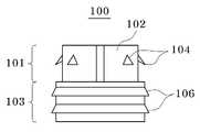
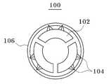
도 1a, 1b, 1c는 각각 본 발명의 바람직한 실시예에 따른 삽입관(100)의 사시도, 측면도, 평면도이다.1A, 1B and 1C are perspective, side and plan views, respectively, of an
도 1b에 도시된 바와 같이, 본 발명의 바람직한 실시예에 따른 삽입관(100)은 전단(101)과 후단(103)으로 나눌 수 있다. 전단(101)에는 참조번호 102로 나타낸 원통형 관에 외부로 돌출된 후크(104)가 다수개 부착되어 있다. 참조번호 102로 나타낸 원통형 관은 전체가 연결되어 있어도 되지만, 도 1a에 나타낸 것처럼 120도 간격으로 3개의 유격을 가져도 된다. 본 발명의 바람직한 실시예에 따르면, 120도 간격으로 분리된 원통형 관(102)의 각각에는 2개씩의 후크(104)가 배치되어 있다.As shown in Figure 1b, the
삽입관(100)의 후단(103)에는 링모양의 돌기(106)가 마련되어 있다. 도 1a 및 1b에 도시된 바와 같이 하나의 삽입관에 2개의 링모양의 돌기(106)가 배치되는 것이 바람직하다. 바람직한 실시예에 의하면, 전단(101)과 후단(103)을 합친 삽입관(100)의 총 길이는 약 4mm이고, 원통형 관의 외부 반지름은 2.25mm이며, 후크는 약 0.5mm의 높이를 가진다. 이러한 바람직한 실시예에 의한 크기는 미세수술에서 가장 흔히 문합하는 2~3 mm 직경의 혈관을 문합하기 위한 문합장치의 크기이며, 혈관 직경의 변화에 따라 문합장치가 크게 혹은 작게 조절될 수 있음은 당연하다.The
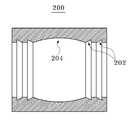
도 2a는 본 발명의 바람직한 실시예에 따른 연결관(200)의 단면도이고, 도 2b는 연결관(200)에 2개의 삽입관(100)이 삽입된 것을 설명하기 위한 도면이다.Figure 2a is a cross-sectional view of a
도 2a 및 도 2b를 참조하면, 연결관(200)은 2개의 삽입관(100)이 내부로 삽입될 수 있는 구조이다. 따라서, 연결관(200)의 내부는 원통형이며 삽입관의 링모양의 돌기(106)에 대응하는 홈(202)을 갖는다. 2개의 삽입관이 양끝에서 연결관의 내부로 삽입되는 구조이므로, 연결관(200)은 내부의 양쪽 끝에 2개씩의 홈(202)을 갖는다. 연결관(200)의 내부 중앙부분은 삽입관의 후크와 맞닿지 않을 정도의 공간(204)을 가져야 한다. 2A and 2B, the connecting
바람직한 실시예에 의하면, 연결관(200)의 길이는 8.1mm이고, 외부 반지름은 3mm이다.According to a preferred embodiment, the length of the connecting
이어서, 도 3a는 혈관(300)이 삽입관(100)에 끼워지기 전의 상태를 나타내고, 도 3b는 혈관(300)이 삽입관(100)에 끼워져 후크에 의해 고정된 후의 상태를 나타내며, 도 3c는 삽입관(100)과 연결관(200)에 의해 혈관(300)이 문합된 후의 상태를 나타낸다.3A shows a state before the
도 3a를 참조하면, 삽입관(100)을 이용하여 혈관(300)을 문합하기 위해 혈관(300)은 삽입관(100)의 내부에 끼워지게 된다. 그리고, 도 3b를 참조하면 혈관(300)이 삽입관(100)을 관통한 후 뒤집어져 후크(104)에 고정되게 된다. 반대쪽 다른 혈관에서도 동일한 방법으로 혈관이 삽입관에 끼워진다.Referring to FIG. 3A, the
도 3c를 참조하면, 혈관(300)이 끼워진 삽입관(100)은 연결관(200)의 양쪽 끝에서 삽입된다. 그러면, 삽입관(100)의 링모양의 돌기(106)에 의해 연결관(200)과 고정되고, 2개의 혈관이 끼워진 삽입관(100)은 연결관의 중앙에서 만나게 된다. 그러면 양 혈관의 내벽이 서로 접촉되어 혈관 내벽은 4~5일 내에 혈관 내피세포로 덮여서 문합이 이루어지게 된다.Referring to FIG. 3C, the
따라서, 이러한 2개의 삽입관과 1개의 연결관을 포함하는 혈관문합 장치를 이용하면, 짧은 시간 동안에 문합을 완료할 수 있고, 양 혈관의 직경이 달라도 그 차이를 손쉽게 극복할 수 있다. 또한, 술기 습득에 필요한 수련 기간이 길지 않으므로, 높은 성공율을 달성할 수 있다.Therefore, by using the vascular anastomosis device including these two insertion tubes and one connecting tube, the anastomosis can be completed in a short time, and even if the diameters of both blood vessels are different, the difference can be easily overcome. In addition, since the training period required for skill acquisition is not long, a high success rate can be achieved.
이러한 본 발명에 의한 혈관문합 장치는 흡수성이어야 한다. 즉, 혈관문합 후 혈관 내면의 간극이 혈관 내피세포로 완전히 메워지는 데는 단지 2-3주 내이면 충분하기 때문에, 흡수성 혈관문합 장치는 수개월 내에 생체에서 흡수되도록 PLGA(polylactic-glycolic acid)를 사용하는 것이 바람직하다. 이때 흡수 시간은 젖산(lactic acid)와 글리콜산(glycolic acid)의 혼합비율을 조정하여 조절하면 된다.The vascular anastomotic device according to the present invention should be absorbent. In other words, it is only 2-3 weeks for the gap between the vessel's inner surface to be completely filled with vascular endothelial cells after vascular anastomosis, so the absorbent vascular anastomosis device uses polylactic-glycolic acid (PLGA) to be absorbed in vivo within months. It is preferable. At this time, the absorption time is adjusted by adjusting the mixing ratio of lactic acid (gactic acid) and glycolic acid (glycolic acid).
구체적으로 설명하면, 생분해성 고분자의 분해는 주로 물이나 토양 속의 미생물에 의해 가수분해될 수 있는 주쇄 결합에서 일어나며, 분해가 진행됨에 따라 분자량을 감소시키고 최종적으로 단량체로 재생되거나 물과 이산화탄소로 분해된다.Specifically, the decomposition of biodegradable polymers occurs mainly in the main chain bonds that can be hydrolyzed by microorganisms in water or soil, and as the decomposition proceeds, the molecular weight is reduced and finally regenerated into monomers or finally decomposed into water and carbon dioxide. .
가수분해성 주쇄로는 'amide, ester, urea, urethane' 등이 잘 알려져 있는데, 이들 중 물리적, 화학적 물성을 가지면서 충분한 분해성을 보이며 미생물 혹은 화학적 합성으로부터 얻어지는 지방족 폴리에스테르가 중요하다. 지방족 폴리에스 테르들은 일반적으로 두 가지 그룹으로 분류되는데, 화학적 합성으로 얻어지는 PLA(poly lactide), PGA(polyglycolide), PCL(poly caprolactone) 등과 미생물로부터 합성되는 PHB(poly hydroxybutyrate)와 HB-co-HV(poly hydroxybutyrate-co-valerate)등으로 분류된다.Hydrolyzable main chains are known as 'amide, ester, urea, urethane', among which aliphatic polyesters having physical and chemical properties and sufficient degradability and obtained from microorganisms or chemical synthesis are important. Aliphatic polyesters are generally classified into two groups: poly lactide (PLA), polyglycolide (PGA), poly caprolactone (PCL), and polyhydroxybutyrate (PHB) and HB-co-HV synthesized from microorganisms. (poly hydroxybutyrate-co-valerate).
이 중에서 PLA는 생분해성, 생체적합성, 우수한 기계적 물성 및 공정 중에 범용 용매에 쉽게 용해되는 특성으로 인해 다양한 생체 의료용 재료로 널리 사용되고 있다. 그러나, PLA는 낮은 생분해 속도를 가지기 때문에 특정 생체 의료용 용도에 한계를 가진다. 따라서, 공중합을 통해 고분자 사슬 내에 글리콜라이드(glycolide)를 도입함으로써 생분해 속도를 제어할 수 있다. PLA와 PGA의 공중합체인 PLGA는 공중합체 내 LA와 GA의 비율에 의해 서로 다른 분해속도를 나타내는데, LA:GA의 비가 50:50일 때 가장 분해속도가 빨라 약 두 달 후에는 완전히 분해된다.Among them, PLA is widely used in various biomedical materials due to its biodegradability, biocompatibility, excellent mechanical properties, and the property of being easily dissolved in a general purpose solvent during the process. However, PLA has a low biodegradation rate and therefore is limited to certain biomedical applications. Accordingly, the rate of biodegradation can be controlled by introducing glycolide into the polymer chain through copolymerization. PLGA, which is a copolymer of PLA and PGA, shows different decomposition rates by the ratio of LA and GA in the copolymer. When the ratio of LA: GA is 50:50, the decomposition rate is fastest and completely degrades after about two months.
도 1a, 1b 및 1c는 각각 본 발명의 바람직한 실시예에 따른 삽입관의 사시도, 측면도 및 평면도이다.1A, 1B and 1C are perspective, side and plan views, respectively, of an insertion tube according to a preferred embodiment of the present invention.
도 2a는 본 발명의 바람직한 실시예에 따른 연결관의 단면도이고, 도 2b는 연결관에 2개의 삽입관이 삽입된 것을 설명하기 위한 도면이다.Figure 2a is a cross-sectional view of the connector according to a preferred embodiment of the present invention, Figure 2b is a view for explaining that two insertion tubes are inserted into the connector.
도 3a는 혈관이 삽입관에 끼워지기 전의 상태를 나타내는 도면, 도 3b는 혈관이 삽입관에 끼워져 후크에 의해 고정된 후의 상태를 나타내는 도면, 도 3c는 삽입관과 연결관에 의해 혈관이 문합된 후의 상태를 나타내는 도면이다.Figure 3a is a view showing a state before the blood vessel is inserted into the insertion tube, Figure 3b is a view showing a state after the blood vessel is inserted into the insertion tube fixed by the hook, Figure 3c is a blood vessel anastomosis by the insertion tube and the connecting tube It is a figure which shows the state after.
도 4는 종래기술에 의한 MAC 시스템을 설명하는 도면이다.4 is a view for explaining a MAC system according to the prior art.
도 5a 및 5b는 종래기술에 의한 MAC 시스템을 이용하여 혈관을 문합하는 방법을 설명하는 도면이다.5A and 5B illustrate a method of anastomosis of blood vessels using a MAC system according to the prior art.
Claims (4)
Translated fromKoreanPriority Applications (9)
| Application Number | Priority Date | Filing Date | Title |
|---|---|---|---|
| KR1020070087047AKR100876516B1 (en) | 2007-08-29 | 2007-08-29 | Absorbent Vascular Anastomosis Device |
| EP08778928AEP2182857A4 (en) | 2007-08-29 | 2008-07-24 | Absorbable vascular anastomotic system |
| US12/674,132US20110106118A1 (en) | 2007-08-29 | 2008-07-24 | Absorbable vascular anastomotic system |
| MX2010001949AMX2010001949A (en) | 2007-08-29 | 2008-07-24 | Absorbable vascular anastomotic system. |
| JP2010522790AJP2010536526A (en) | 2007-08-29 | 2008-07-24 | Absorptive vascular anastomosis device {Absorble vascular molecular system} |
| BRPI0815261ABRPI0815261A2 (en) | 2007-08-29 | 2008-07-24 | "absorbable vascular anastomotic system" |
| PCT/KR2008/004335WO2009028799A2 (en) | 2007-08-29 | 2008-07-24 | Absorbable vascular anastomotic system |
| CN2008801045623ACN101815473B (en) | 2007-08-29 | 2008-07-24 | Absorbable vascular anastomotic system |
| CA2696477ACA2696477A1 (en) | 2007-08-29 | 2008-07-24 | Absorbable vascular anastomotic system |
Applications Claiming Priority (1)
| Application Number | Priority Date | Filing Date | Title |
|---|---|---|---|
| KR1020070087047AKR100876516B1 (en) | 2007-08-29 | 2007-08-29 | Absorbent Vascular Anastomosis Device |
Publications (1)
| Publication Number | Publication Date |
|---|---|
| KR100876516B1true KR100876516B1 (en) | 2008-12-31 |
Family
ID=40373362
Family Applications (1)
| Application Number | Title | Priority Date | Filing Date |
|---|---|---|---|
| KR1020070087047AExpired - Fee RelatedKR100876516B1 (en) | 2007-08-29 | 2007-08-29 | Absorbent Vascular Anastomosis Device |
Country Status (9)
| Country | Link |
|---|---|
| US (1) | US20110106118A1 (en) |
| EP (1) | EP2182857A4 (en) |
| JP (1) | JP2010536526A (en) |
| KR (1) | KR100876516B1 (en) |
| CN (1) | CN101815473B (en) |
| BR (1) | BRPI0815261A2 (en) |
| CA (1) | CA2696477A1 (en) |
| MX (1) | MX2010001949A (en) |
| WO (1) | WO2009028799A2 (en) |
Cited By (7)
| Publication number | Priority date | Publication date | Assignee | Title |
|---|---|---|---|---|
| KR101026933B1 (en) | 2010-11-08 | 2011-04-04 | 주식회사 메타바이오메드 | Vascular anastomosis device |
| KR101070697B1 (en) | 2010-12-15 | 2011-10-07 | (주)트리플씨메디칼 | Bonded isomorph integral anastomosis ring set and isomorphic integrated anastomosis ring |
| KR101145404B1 (en) | 2011-12-12 | 2012-05-15 | 주식회사 메타바이오메드 | Vascular anastomosis device |
| WO2012074141A1 (en)* | 2010-11-29 | 2012-06-07 | (주)알씨티 | Automatic blood vessel anastomosis device using a suture |
| KR101688735B1 (en)* | 2015-06-22 | 2016-12-22 | 연세대학교 산학협력단 | Blood vessel anastomosis device with stent structure |
| CN117064474A (en)* | 2023-10-17 | 2023-11-17 | 山东百多安医疗器械股份有限公司 | Degradable vascular anastomosis device |
| WO2025198299A1 (en)* | 2024-03-19 | 2025-09-25 | 계명대학교 산학협력단 | Rotational convex-concave coupling vascular anastomosis device |
Families Citing this family (25)
| Publication number | Priority date | Publication date | Assignee | Title |
|---|---|---|---|---|
| US11207457B2 (en) | 2004-08-27 | 2021-12-28 | Edwards Lifesciences Corporation | Device and method for establishing an artificial arterio-venous fistula |
| WO2009144728A1 (en)* | 2008-05-28 | 2009-12-03 | Seamvad Ltd. | Anastomosis device |
| EP2421468B1 (en)* | 2009-04-20 | 2016-12-07 | Rox Medical, Inc. | Device for establishing an artificial arterio-venous fistula |
| EP2558004A4 (en)* | 2010-04-16 | 2015-04-29 | Univ Utah Res Found | METHODS, DEVICES, AND APPARATUS FOR REALIZING VASCULAR ANASTOMOSIS |
| WO2012161627A1 (en)* | 2011-05-23 | 2012-11-29 | Prozeo Vascular Implant Ab | A device, a tool means, a kit and a method for anastomosis |
| EP2851010A4 (en)* | 2012-01-30 | 2016-03-30 | Univ Kurume | DEVICE FOR VASCULAR ANASTOMOSIS AND METHOD FOR VASCULAR ANASTOMOSIS |
| CN106163424B (en)* | 2013-12-27 | 2019-08-20 | 犹他大学研究基金会 | Blood vessel coupling device |
| CN109257925A (en)* | 2016-03-17 | 2019-01-22 | 医药连接技术-医连技术-M.C.T.有限公司 | Medicine connector apparatus |
| TWI783067B (en)* | 2017-11-10 | 2022-11-11 | 凡克生醫科技股份有限公司 | Blood vessel anastomosis set |
| CN109199499B (en)* | 2018-10-17 | 2020-10-27 | 盐木医疗科技(北京)有限公司 | Small lumen anastomat |
| EP4017384A1 (en) | 2019-08-22 | 2022-06-29 | Edwards Lifesciences Corporation | Puncture needles |
| CN114929122A (en)* | 2019-11-08 | 2022-08-19 | 阿瓦萨有限公司 | Tubular tissue converter |
| CR20220218A (en) | 2019-11-14 | 2022-08-22 | Edwards Lifesciences Corp | Transcatheter medical implant delivery |
| US12329383B2 (en) | 2019-11-18 | 2025-06-17 | Buck Surgical, Inc. | Anastomotic coupler |
| US12303131B2 (en) | 2019-11-18 | 2025-05-20 | Buck Surgical, Inc. | Anastomotic coupler |
| BR112022004182B1 (en)* | 2019-11-18 | 2023-02-07 | Buck Surgical Llc | ANASTOMOTIC COUPLER |
| US12201298B2 (en) | 2019-11-18 | 2025-01-21 | Buck Surgical Llc | Anastomotic coupler |
| CN110811729A (en)* | 2019-12-11 | 2020-02-21 | 西安交通大学医学院第一附属医院 | Buckle formula blood vessel anastomosis device |
| CN110811728A (en)* | 2019-12-11 | 2020-02-21 | 西安交通大学医学院第一附属医院 | An anastomosis device of two-end clamping type vascular anastomosis |
| CN110811730A (en)* | 2019-12-11 | 2020-02-21 | 西安交通大学医学院第一附属医院 | A rivet type vascular anastomosis device |
| CN112998684B (en)* | 2021-02-24 | 2023-03-31 | 山东第一医科大学附属省立医院(山东省立医院) | Blood flow dynamic monitor |
| CN113648011B (en)* | 2021-08-05 | 2023-08-25 | 北京清华长庚医院 | Biodegradable blood vessel rapid anastomosis device |
| CN113413254B (en)* | 2021-08-24 | 2021-11-16 | 南通欣昌减震器有限公司 | Human tubular structure rubber support |
| CN116636893A (en)* | 2023-05-04 | 2023-08-25 | 北京航空航天大学 | Magnetic suction vessel anastomat |
| CN119366991B (en)* | 2024-12-31 | 2025-04-08 | 华融科创生物科技(天津)有限公司 | Split anastomosis locking assembly |
Citations (3)
| Publication number | Priority date | Publication date | Assignee | Title |
|---|---|---|---|---|
| US4523592A (en) | 1983-04-25 | 1985-06-18 | Rollin K. Daniel P.S.C. | Anastomotic coupling means capable of end-to-end and end-to-side anastomosis |
| WO2006009503A1 (en) | 2004-07-22 | 2006-01-26 | Vascon Ab | Anastomosis device and method |
| US20060085017A1 (en) | 2004-10-19 | 2006-04-20 | I. & S. Idee & Sviluppo S.R.L. | Vascular graft |
Family Cites Families (7)
| Publication number | Priority date | Publication date | Assignee | Title |
|---|---|---|---|---|
| US2179930A (en)* | 1937-09-10 | 1939-11-14 | George P Harrington | Hose coupling |
| US2453056A (en)* | 1947-03-12 | 1948-11-02 | Zack William Edwin | Surgical anastomosis apparatus and method |
| US3221746A (en)* | 1963-01-25 | 1965-12-07 | Noble John William | Surgical connecting device |
| US4214586A (en)* | 1978-11-30 | 1980-07-29 | Ethicon, Inc. | Anastomotic coupling device |
| US4948175A (en)* | 1980-10-29 | 1990-08-14 | Proprietary Technology, Inc. | Swivelable quick connector assembly |
| IT1320958B1 (en)* | 2000-03-28 | 2003-12-18 | New Age Costrunctions And Engi | APPARATUS AND METHOD FOR ANASTOMOSIS. |
| US20070142850A1 (en)* | 2005-12-15 | 2007-06-21 | David Fowler | Compression anastomosis device |
- 2007
- 2007-08-29KRKR1020070087047Apatent/KR100876516B1/ennot_activeExpired - Fee Related
- 2008
- 2008-07-24CACA2696477Apatent/CA2696477A1/ennot_activeAbandoned
- 2008-07-24BRBRPI0815261Apatent/BRPI0815261A2/ennot_activeIP Right Cessation
- 2008-07-24WOPCT/KR2008/004335patent/WO2009028799A2/enactiveApplication Filing
- 2008-07-24MXMX2010001949Apatent/MX2010001949A/ennot_activeApplication Discontinuation
- 2008-07-24USUS12/674,132patent/US20110106118A1/ennot_activeAbandoned
- 2008-07-24JPJP2010522790Apatent/JP2010536526A/enactivePending
- 2008-07-24EPEP08778928Apatent/EP2182857A4/ennot_activeWithdrawn
- 2008-07-24CNCN2008801045623Apatent/CN101815473B/ennot_activeExpired - Fee Related
Patent Citations (3)
| Publication number | Priority date | Publication date | Assignee | Title |
|---|---|---|---|---|
| US4523592A (en) | 1983-04-25 | 1985-06-18 | Rollin K. Daniel P.S.C. | Anastomotic coupling means capable of end-to-end and end-to-side anastomosis |
| WO2006009503A1 (en) | 2004-07-22 | 2006-01-26 | Vascon Ab | Anastomosis device and method |
| US20060085017A1 (en) | 2004-10-19 | 2006-04-20 | I. & S. Idee & Sviluppo S.R.L. | Vascular graft |
Cited By (8)
| Publication number | Priority date | Publication date | Assignee | Title |
|---|---|---|---|---|
| KR101026933B1 (en) | 2010-11-08 | 2011-04-04 | 주식회사 메타바이오메드 | Vascular anastomosis device |
| WO2012074141A1 (en)* | 2010-11-29 | 2012-06-07 | (주)알씨티 | Automatic blood vessel anastomosis device using a suture |
| KR101070697B1 (en) | 2010-12-15 | 2011-10-07 | (주)트리플씨메디칼 | Bonded isomorph integral anastomosis ring set and isomorphic integrated anastomosis ring |
| KR101145404B1 (en) | 2011-12-12 | 2012-05-15 | 주식회사 메타바이오메드 | Vascular anastomosis device |
| KR101688735B1 (en)* | 2015-06-22 | 2016-12-22 | 연세대학교 산학협력단 | Blood vessel anastomosis device with stent structure |
| CN117064474A (en)* | 2023-10-17 | 2023-11-17 | 山东百多安医疗器械股份有限公司 | Degradable vascular anastomosis device |
| CN117064474B (en)* | 2023-10-17 | 2024-01-05 | 山东百多安医疗器械股份有限公司 | Degradable vascular anastomosis device |
| WO2025198299A1 (en)* | 2024-03-19 | 2025-09-25 | 계명대학교 산학협력단 | Rotational convex-concave coupling vascular anastomosis device |
Also Published As
| Publication number | Publication date |
|---|---|
| JP2010536526A (en) | 2010-12-02 |
| EP2182857A2 (en) | 2010-05-12 |
| CN101815473A (en) | 2010-08-25 |
| US20110106118A1 (en) | 2011-05-05 |
| MX2010001949A (en) | 2010-03-10 |
| CN101815473B (en) | 2012-11-07 |
| WO2009028799A3 (en) | 2009-04-23 |
| BRPI0815261A2 (en) | 2015-09-08 |
| CA2696477A1 (en) | 2009-03-05 |
| WO2009028799A2 (en) | 2009-03-05 |
| EP2182857A4 (en) | 2010-12-15 |
Similar Documents
| Publication | Publication Date | Title |
|---|---|---|
| KR100876516B1 (en) | Absorbent Vascular Anastomosis Device | |
| US11911034B2 (en) | Adjunct materials and methods of using same in surgical methods for tissue sealing | |
| Martin et al. | Medical applications of poly-4-hydroxybutyrate: a strong flexible absorbable biomaterial | |
| KR101577602B1 (en) | Self-retaining sutures with bi-directional retainers or uni-directional retainers | |
| ES2295021T3 (en) | USE AND MEDICAL APPLICATIONS OF POLYMER POLYMERS (HYDROXIALCANOATS). | |
| CN102481149B (en) | There is the coating line of the anchoring structure for carrying out grappling in biological tissue | |
| ES2527857T3 (en) | Medical tissues and fibers of polyhydroxyalkanoate | |
| US9011485B2 (en) | Implantable biodegradable wound closure device and method | |
| JPH0686827A (en) | Vessel stent and vessel stent inserting device | |
| JP2007513648A (en) | Intravascular filter with bioabsorbable centering element | |
| CN1151859A (en) | One-way suture retaining device for braided sutures | |
| JPH0263465A (en) | Materials for periodontal tissue regeneration | |
| JPH11313895A (en) | Bellows medical structure and device using the same | |
| KR102224938B1 (en) | Vascular anastomosis device containing biodegradable shape memory polymer film and stent | |
| WO2019156230A1 (en) | Medical apparatus and adhesion promoting device using same | |
| JP6944162B2 (en) | Stent for anastomosis of different organs | |
| US8940012B2 (en) | Intravascular filter with biodegradable force-reducing element | |
| KR101748551B1 (en) | Shape memory polymer based vascular anastomosis device | |
| US20100305603A1 (en) | Shape-Changing Medical Device, Kit, Method Of Production, And Method Of Use | |
| US20130226277A1 (en) | Slide fastener bioabsorbable stent and application thereof | |
| Tammela et al. | Biodegradable urethral stents. | |
| KR20200138739A (en) | System for vascular bypass prosthesis placement | |
| US5854381A (en) | Use of lactide polymers for adhesion prophylaxis | |
| JP3038068B2 (en) | Connector for vascular anastomosis and method of manufacturing the same | |
| KR20130141977A (en) | Bioabsorbable vascular anastomosis device |
Legal Events
| Date | Code | Title | Description |
|---|---|---|---|
| A201 | Request for examination | ||
| PA0109 | Patent application | St.27 status event code:A-0-1-A10-A12-nap-PA0109 | |
| PA0201 | Request for examination | St.27 status event code:A-1-2-D10-D11-exm-PA0201 | |
| D13-X000 | Search requested | St.27 status event code:A-1-2-D10-D13-srh-X000 | |
| D14-X000 | Search report completed | St.27 status event code:A-1-2-D10-D14-srh-X000 | |
| R18-X000 | Changes to party contact information recorded | St.27 status event code:A-3-3-R10-R18-oth-X000 | |
| E701 | Decision to grant or registration of patent right | ||
| PE0701 | Decision of registration | St.27 status event code:A-1-2-D10-D22-exm-PE0701 | |
| GRNT | Written decision to grant | ||
| PR0701 | Registration of establishment | St.27 status event code:A-2-4-F10-F11-exm-PR0701 | |
| PR1002 | Payment of registration fee | St.27 status event code:A-2-2-U10-U11-oth-PR1002 Fee payment year number:1 | |
| PG1601 | Publication of registration | St.27 status event code:A-4-4-Q10-Q13-nap-PG1601 | |
| PN2301 | Change of applicant | St.27 status event code:A-5-5-R10-R11-asn-PN2301 | |
| PN2301 | Change of applicant | St.27 status event code:A-5-5-R10-R14-asn-PN2301 | |
| P14-X000 | Amendment of ip right document requested | St.27 status event code:A-5-5-P10-P14-nap-X000 | |
| P16-X000 | Ip right document amended | St.27 status event code:A-5-5-P10-P16-nap-X000 | |
| Q16-X000 | A copy of ip right certificate issued | St.27 status event code:A-4-4-Q10-Q16-nap-X000 | |
| R18-X000 | Changes to party contact information recorded | St.27 status event code:A-5-5-R10-R18-oth-X000 | |
| PR1001 | Payment of annual fee | St.27 status event code:A-4-4-U10-U11-oth-PR1001 Fee payment year number:4 | |
| FPAY | Annual fee payment | Payment date:20121109 Year of fee payment:5 | |
| PR1001 | Payment of annual fee | St.27 status event code:A-4-4-U10-U11-oth-PR1001 Fee payment year number:5 | |
| FPAY | Annual fee payment | Payment date:20131203 Year of fee payment:6 | |
| PR1001 | Payment of annual fee | St.27 status event code:A-4-4-U10-U11-oth-PR1001 Fee payment year number:6 | |
| R18-X000 | Changes to party contact information recorded | St.27 status event code:A-5-5-R10-R18-oth-X000 | |
| FPAY | Annual fee payment | Payment date:20141204 Year of fee payment:7 | |
| PR1001 | Payment of annual fee | St.27 status event code:A-4-4-U10-U11-oth-PR1001 Fee payment year number:7 | |
| R18-X000 | Changes to party contact information recorded | St.27 status event code:A-5-5-R10-R18-oth-X000 | |
| PR1001 | Payment of annual fee | St.27 status event code:A-4-4-U10-U11-oth-PR1001 Fee payment year number:8 | |
| FPAY | Annual fee payment | Payment date:20161222 Year of fee payment:9 | |
| PR1001 | Payment of annual fee | St.27 status event code:A-4-4-U10-U11-oth-PR1001 Fee payment year number:9 | |
| FPAY | Annual fee payment | Payment date:20171113 Year of fee payment:10 | |
| PR1001 | Payment of annual fee | St.27 status event code:A-4-4-U10-U11-oth-PR1001 Fee payment year number:10 | |
| PR1001 | Payment of annual fee | St.27 status event code:A-4-4-U10-U11-oth-PR1001 Fee payment year number:11 | |
| FPAY | Annual fee payment | Payment date:20191211 Year of fee payment:12 | |
| PR1001 | Payment of annual fee | St.27 status event code:A-4-4-U10-U11-oth-PR1001 Fee payment year number:12 | |
| PR1001 | Payment of annual fee | St.27 status event code:A-4-4-U10-U11-oth-PR1001 Fee payment year number:13 | |
| PR1001 | Payment of annual fee | St.27 status event code:A-4-4-U10-U11-oth-PR1001 Fee payment year number:14 | |
| PR1001 | Payment of annual fee | St.27 status event code:A-4-4-U10-U11-oth-PR1001 Fee payment year number:15 | |
| PC1903 | Unpaid annual fee | St.27 status event code:A-4-4-U10-U13-oth-PC1903 Not in force date:20231223 Payment event data comment text:Termination Category : DEFAULT_OF_REGISTRATION_FEE | |
| PC1903 | Unpaid annual fee | St.27 status event code:N-4-6-H10-H13-oth-PC1903 Ip right cessation event data comment text:Termination Category : DEFAULT_OF_REGISTRATION_FEE Not in force date:20231223 |