KR100875813B1 - Fluid Mass Flow Controller and Its Operation Method - Google Patents
Fluid Mass Flow Controller and Its Operation MethodDownload PDFInfo
- Publication number
- KR100875813B1 KR100875813B1KR1020077027614AKR20077027614AKR100875813B1KR 100875813 B1KR100875813 B1KR 100875813B1KR 1020077027614 AKR1020077027614 AKR 1020077027614AKR 20077027614 AKR20077027614 AKR 20077027614AKR 100875813 B1KR100875813 B1KR 100875813B1
- Authority
- KR
- South Korea
- Prior art keywords
- flow
- controller
- flow restrictor
- restrictor
- pressure
- Prior art date
- Legal status (The legal status is an assumption and is not a legal conclusion. Google has not performed a legal analysis and makes no representation as to the accuracy of the status listed.)
- Expired - Fee Related
Links
Images


Classifications
- G—PHYSICS
- G05—CONTROLLING; REGULATING
- G05D—SYSTEMS FOR CONTROLLING OR REGULATING NON-ELECTRIC VARIABLES
- G05D7/00—Control of flow
- G05D7/06—Control of flow characterised by the use of electric means
- G—PHYSICS
- G05—CONTROLLING; REGULATING
- G05D—SYSTEMS FOR CONTROLLING OR REGULATING NON-ELECTRIC VARIABLES
- G05D7/00—Control of flow
- G05D7/06—Control of flow characterised by the use of electric means
- G05D7/0617—Control of flow characterised by the use of electric means specially adapted for fluid materials
- G05D7/0629—Control of flow characterised by the use of electric means specially adapted for fluid materials characterised by the type of regulator means
- G05D7/0635—Control of flow characterised by the use of electric means specially adapted for fluid materials characterised by the type of regulator means by action on throttling means
- Y—GENERAL TAGGING OF NEW TECHNOLOGICAL DEVELOPMENTS; GENERAL TAGGING OF CROSS-SECTIONAL TECHNOLOGIES SPANNING OVER SEVERAL SECTIONS OF THE IPC; TECHNICAL SUBJECTS COVERED BY FORMER USPC CROSS-REFERENCE ART COLLECTIONS [XRACs] AND DIGESTS
- Y10—TECHNICAL SUBJECTS COVERED BY FORMER USPC
- Y10T—TECHNICAL SUBJECTS COVERED BY FORMER US CLASSIFICATION
- Y10T137/00—Fluid handling
- Y10T137/0318—Processes
- Y10T137/0324—With control of flow by a condition or characteristic of a fluid
- Y10T137/0368—By speed of fluid
- Y—GENERAL TAGGING OF NEW TECHNOLOGICAL DEVELOPMENTS; GENERAL TAGGING OF CROSS-SECTIONAL TECHNOLOGIES SPANNING OVER SEVERAL SECTIONS OF THE IPC; TECHNICAL SUBJECTS COVERED BY FORMER USPC CROSS-REFERENCE ART COLLECTIONS [XRACs] AND DIGESTS
- Y10—TECHNICAL SUBJECTS COVERED BY FORMER USPC
- Y10T—TECHNICAL SUBJECTS COVERED BY FORMER US CLASSIFICATION
- Y10T137/00—Fluid handling
- Y10T137/7722—Line condition change responsive valves
- Y10T137/7758—Pilot or servo controlled
- Y10T137/7759—Responsive to change in rate of fluid flow
- Y—GENERAL TAGGING OF NEW TECHNOLOGICAL DEVELOPMENTS; GENERAL TAGGING OF CROSS-SECTIONAL TECHNOLOGIES SPANNING OVER SEVERAL SECTIONS OF THE IPC; TECHNICAL SUBJECTS COVERED BY FORMER USPC CROSS-REFERENCE ART COLLECTIONS [XRACs] AND DIGESTS
- Y10—TECHNICAL SUBJECTS COVERED BY FORMER USPC
- Y10T—TECHNICAL SUBJECTS COVERED BY FORMER US CLASSIFICATION
- Y10T137/00—Fluid handling
- Y10T137/7722—Line condition change responsive valves
- Y10T137/7758—Pilot or servo controlled
- Y10T137/7761—Electrically actuated valve
Landscapes
- Physics & Mathematics (AREA)
- General Physics & Mathematics (AREA)
- Engineering & Computer Science (AREA)
- Automation & Control Theory (AREA)
- Flow Control (AREA)
- Electrical Discharge Machining, Electrochemical Machining, And Combined Machining (AREA)
Abstract
Description
Translated fromKorean본 발명은 유체 질량유량 제어기에 관한 것으로서, 특히 반도체 장치의 제조에 사용된 유독성 또는 고반응성 가스의 유동을 제어하는 유체 질량유량 제어기와, 상기 제어기의 유동 제한장치를 가로지른 유체 압력차와 상기 제어기에 의해 관찰된 하류 유체 압력을 상관시키는 데이터에 기초하여 제어기를 작동시키는 방법에 관한 것이다.The present invention relates to a fluid mass flow controller, in particular a fluid mass flow controller for controlling the flow of toxic or highly reactive gases used in the manufacture of semiconductor devices, a fluid pressure differential across the flow restrictor of the controller and the controller. A method of operating a controller based on data correlating downstream fluid pressure observed by
정밀한 유체 질량유량 제어기, 특히 예를 들면 반도체 장치의 제조에 사용된 유독성 또는 고반응성 가스와 같은 유체의 질량유동율을 제어하기 위한 유량 제어기가 개발되고 있다. 반도체 제조 분야에 있어서, 에칭 및 기상증착공정에 다양한 가스가 사용되고 있으며, 이들 가스는 인간에 해롭고 또한 대기에 노출되었을 때 고반응성을 가진다. 질량유량 제어기는 유체의 열 특성에 기초하여 전술한 형태의 유체의 유동율을 측정하고 제어하기 위해 개발되고 있다. 다른 유체 질량유량 제어기는 유동 제한장치 또는 오리피스를 가로지른 압력차를 측정하는 것에 기초하여 개발되고 있다. 종래 기술의 유체 질량유량 제어기는 유량 제어기의 많은 적용에 대해 의문점을 가지고 있다.Precision fluid mass flow controllers, in particular flow controllers for controlling the mass flow rate of fluids such as toxic or highly reactive gases used in the manufacture of semiconductor devices, have been developed. In the field of semiconductor manufacturing, various gases are used in etching and vapor deposition processes, which are harmful to humans and have high reactivity when exposed to the atmosphere. Mass flow controllers have been developed to measure and control the flow rates of fluids of the type described above based on the thermal properties of the fluid. Other fluid mass flow controllers have been developed based on measuring the pressure differential across the flow restrictor or orifice. Prior art fluid mass flow controllers have questions about many applications of flow controllers.
반도체 제조공정은 제조챔버내로 매우 정확한 양의 유체(가스)의 방출을 요구한다. 예를 들면, 분당 20리터 이상의 고속에서부터 분당 수십분의 1 세제곱센치미터의 저속범위의 유동율(CCM)이 요구될 수 있다. 더욱이, 반도체 제조에서의 반응성 가스를 제어하는데 사용된 유량 제어기의 반응시간과 안정성은 "온(ON)"신호에 대해 0.5 내지 1.0초내에서 요구된 유체 유동율을 안정화시킬 수 있는 제어기를 요구한다. 제조공정은 수초부터 수시간에 걸쳐 이루어질 수 있으며, 유체 유량 제어기의 정지 반응시간은 통상 1초 이내를 요구한다. 이러한 속도에서 열에 기초한 유체 질량유량 제어기의 반응 및 안정화에 대한 능력은 달성되기 어렵다.The semiconductor manufacturing process requires the release of a very accurate amount of fluid (gas) into the manufacturing chamber. For example, a flow rate (CCM) ranging from a high speed of more than 20 liters per minute to a few tens of cubic centimeters per minute may be required. Moreover, the reaction time and stability of the flow controllers used to control reactive gases in semiconductor fabrication require controllers that can stabilize the required fluid flow rates within 0.5 to 1.0 seconds for the " ON " signal. The manufacturing process can take from a few seconds to several hours and the stop reaction time of the fluid flow controller typically requires less than one second. At this rate, the ability to react and stabilize the heat-based fluid mass flow controller is difficult to achieve.
일반적인 형태의 종래 기술의 유체 질량유량 제어기와 결합된 다른 문제점은 다양한 처리 유체에 대해 제어기 측정 요건에 관한 것이다. 종래 기술의 유체 질량유량 제어기는 전환 인자 및 전환 데이터 세트의 개발을 요구하는 불활성 또는 비독성 유체를 사용하여 측정되고 있다. 각 제어기의 측정을 위해 유독성 또는 고반응성 유체를 사용하는 것은 금지되어 있고 조작하는 사람에게 위험하기 때문에 종래 기술의 유체 질량유량 제어기는 질소 또는 아르곤과 같은 불활성 가스 또는 질량유량 제어기에 의해 제어되는 공정 유체의 특성과 유사한 특성의 유체를 이용하여 측정한다. 측정 유체와 전환 인자를 사용하는 이 처리는 질량유량 제어기의 작동에 오류를 발생시켜 시간 소모를 일으키고 따라서 고비용이다. 종래 기술의 질량유량 제어기의 부정확함과, 교체 공정 뿐만아니라 초기 설정동안 제어기를 측정하는데 요구된 비용과 시간은 반도체 장치의 제조를 포함하는 많은 제조공정에 실질적인 비용증가를 가져오며 유체 질량유량 제어기의 어떤 개선이 높게 요구되고 있다.Another problem, combined with the conventional type of mass flow controller of the prior art, relates to controller measurement requirements for various processing fluids. Prior art fluid mass flow controllers are being measured using inert or non-toxic fluids that require the development of conversion factors and conversion data sets. Since the use of toxic or highly reactive fluids for the measurement of each controller is prohibited and dangerous to the operator, prior art fluid mass flow controllers are process fluids controlled by an inert gas such as nitrogen or argon or a mass flow controller. Measure with a fluid of similar properties to. This process, using the measuring fluid and the conversion factor, causes errors in the operation of the mass flow controller, which leads to time consuming and therefore high cost. The inaccuracies of the prior art mass flow controllers, and the cost and time required to measure the controllers during initial setup as well as replacement processes, result in substantial cost increases in many manufacturing processes, including the manufacture of semiconductor devices. Some improvement is highly demanded.
따라서, 유체 질량유량 제어기, 특히 전술한 것과 같은 제조공정에 사용된 형태의 질량유량 제어기에 대해 다수의 소망이 나타나고 있다. 이러한 소망은 제어기 설정포인트의 몇 퍼센트(적어도 1퍼센트가 바람직함)내의 제어기 정확성, 열 기초 질량유량 제어기에 의해 경험된 바와 같이 "정상"온도 상하 및 다양한 위치 또는 자세(즉, 우측은 올라가고, 비스듬하거나 또는 거꾸로된)에서 정확도의 손실없이 작동되며, 유동율의 넓은 범위에 걸쳐 정확한 측정 및 제어가 이루어지며, 안정된 유동 조건을 달성하도록 "작동(turn-on)"으로부터 빠르게 반응하며, 제조공정동안 유체 유량분배시스템 외부에서의 유량 제어기의 변경 및 서비스가가 용이할 것 등을 포함하고 있다. 유체 질량유량 제어기에서의 다른 소망은 제조 시간중 완성된 제어기를 측정하거나 또는 서비스후 제어기를 재측정하는 요구가 없고, 쉽게 교환할 수 있는 유동 제한장치 또는 오리피스, 서비스 또는 유량 제한장치의 교체후 유량 제어기의 작동성 및 정확도의 검증 용이, 유독성 및/또는 반응성 유체의 넓은 변화에 대한 유동율 제어의 정확성, 반도체 제조공정에 사용된 가스형태의 수많은 유체를 특정하는 것, 서로다른 가스 또는 액체 형태의 유체에 대한 유동율에 대해 제어기 가동 데이터의 쉬운 변경을 포함한다. 이들은 본 발명에 의해 개발되었다.Accordingly, a number of desires have emerged for fluid mass flow controllers, especially mass flow controllers of the type used in manufacturing processes such as those described above. This desire can be attributed to controller accuracy within a few percent of the controller setpoint (at least 1 percent is preferred), “normal” temperature up and down and various positions or postures (ie right to rise, skewed) as experienced by thermally based mass flow controllers. Or inverted) without loss of accuracy, accurate measurement and control over a wide range of flow rates, rapid response from "turn-on" to achieve stable flow conditions, and It is easy to change and service the flow controller outside the flow distribution system. Another desire in fluid mass flow controllers is that there is no need to measure the finished controller during manufacturing time or to re-measure the post-service controller, and it is easy to replace the flow restrictor or orifice, service or flow restrictor after replacement. Easy verification of the operability and accuracy of the controller, accuracy of flow rate control over wide variations of toxic and / or reactive fluids, specifying numerous fluids in the form of gases used in semiconductor manufacturing processes, fluids in different gas or liquid forms It includes easy change of controller operation data for flow rate for. These have been developed by the present invention.
본 발명은 개선된 유체 질량유량 제어기 및 그의 작동방법을 제공한다. 특히, 개선된 질량유량 제어기와 그의 작동방법은 반도체 장치의 제조에 사용된 가스형태의 유체의 유량을 제어하는 것과 조합하여 사용될 수 있다.The present invention provides an improved fluid mass flow controller and its operating method. In particular, the improved mass flow controller and its method of operation can be used in combination with controlling the flow rate of a gaseous fluid used in the manufacture of semiconductor devices.
본 발명의 한 관점에 따르면, 유동 제한장치를 가로지른 압력차와 상기 유동 제한장치의 하류 압력의 측정을 이용하여 특정 온도에서의 특정 유체의 실제 질량유량을 정확하게 판독할 수 있는 유체 질량유량 제어기를 제공한다. 이러한 측정은 2개의 압력 센서 또는 변환기만을 사용하여 실행되며 측정되어지는 유체의 폭넓은 온도범위에 걸쳐 실행될 수 있다.According to one aspect of the present invention, there is provided a fluid mass flow controller that can accurately read the actual mass flow rate of a particular fluid at a specific temperature using the measurement of the pressure difference across the flow restrictor and the downstream pressure of the flow restrictor. to provide. This measurement is carried out using only two pressure sensors or transducers and can be carried out over a wide temperature range of the fluid being measured.
본 발명은 개선된 유체 질량유량 제어기, 특히 반도체 장치의 제조에 사용된 유독성 및 반응성 가스의 질량유동율을 제어하는 제어기를 제공하는 것으로서, 유량 제어기는 소망 설정 포인트 유동율에서 안정화되도록 빠른 반응 시간과 설정 포인트 조건내의 1퍼센트 미만의 오류의 정확도를 가진다. 또한, 제어기는 100 내지 1의 최대 내지 최소 유동율의 폭넓은 범위로 질량유동율을 측정할 수 있다. 질량유량 제어기는 공정 유체 또는 측정 유체의 측정을 요구하지 않으며, 따라서 유동측정공정에 있어서 전환 인자를 요구하지 않는다.The present invention provides an improved fluid mass flow controller, in particular a controller for controlling the mass flow rate of toxic and reactive gases used in the manufacture of semiconductor devices, wherein the flow controller has a fast reaction time and set point to stabilize at the desired set point flow rate. Has an accuracy of less than 1 percent of error in the condition. In addition, the controller can measure the mass flow rate over a wide range of maximum to minimum flow rates of 100-1. The mass flow controller does not require measurement of the process fluid or the measurement fluid and therefore does not require a conversion factor in the flow measurement process.
또한, 본 발명은 제어기가 노출되고 제어기가 작동될 때의 압력차와 하류 압력 범위내의 선택된 유체의 질량유량에 대한 데이터를 이용하여 유동 제한장치를 가로지른 압력차와 유동 제한장치의 하류 압력의 측정에 의해 작동하는 개선된 질량유량 제어기를 제공한다. 본 발명의 질량유량 제어기와 유량계는 대기압으로부 터 유독성 또는 반응성 가스에 대한 안전 인도 시스템에서 경험된 진공 조건으로의 흡입 압력의 폭넓은 범위에 걸쳐 작동가능하다. 또한, 본 발명은 디지털 신호 프로세서와 같은 적절한 프로세서 회로, 상기 데이터를 기억하고 필요시 추가 데이터 세트를 수신하는 비휘발성 메모리를 포함하는 제어 시스템과 조합되는 유체 질량유량 제어기를 포함한다.In addition, the present invention measures the pressure differential across the flow restrictor and the downstream pressure of the flow restrictor using data on the pressure difference when the controller is exposed and the controller is operated and the mass flow rate of the selected fluid within the downstream pressure range. It provides an improved mass flow controller that operates by. The mass flow controllers and flow meters of the present invention are operable over a wide range of suction pressures from atmospheric pressure to vacuum conditions experienced in safety delivery systems for toxic or reactive gases. The invention also includes a fluid mass flow controller in combination with a suitable processor circuit, such as a digital signal processor, and a control system including a nonvolatile memory that stores the data and receives additional data sets as needed.
본 발명은 교체가능한 유동 제한장치, 하나 이상의 압력 변환기 및 제어기와 조합된 단일 유량제어밸브의 빠른 교체에 적합한 묘듈 형태의 기계적으로 미완성된 구성인 유체 질량유량 제어기를 제공한다.The present invention provides a fluid mass flow controller in a mechanically unfinished configuration in the form of a module suitable for quick replacement of a single flow control valve in combination with a replaceable flow restrictor, one or more pressure transducers and a controller.
또한, 본 발명은 본 발명에 따른 유체 질량유량 제어기 또는 유량계에 기초한 압력을 사용하기에 적합하며, 다른 적용에도 이용가능하며 유독성 및 반응성 가스를 대해 이용하기에 적합한 다양한 유체에 대한 데이터 세트로서 이용가능한 압력차와 하류 압력의 유동 데이터를 갖는 유동 제한장치를 제공한다.The invention is also suitable for use with a pressure based on a fluid mass flow controller or flow meter according to the invention, which is also applicable to other applications and as a data set for various fluids suitable for use with toxic and reactive gases. Provide a flow restrictor with flow data of pressure differential and downstream pressure.
또한, 본 발명은 유동 제한장치를 가로지른 압력차와 유동 제한장치의 하류 유체 압력을 측정하는 것에 의해 유체의 질량유동율을 측정 및/또는 제어하기 위한 방법, 특히 하류 압력이 대기압 이하인 작동 조건에 한정되지 않는 방법을 제공한다. 본 발명은 측정 유체로 제어기의 측정을 요구하지 않으며, 유독성 또는 고반응성의 다양한 형태의 공정 유체에 대해 제어기의 유동 제한장치에 대한 설정된 데이터 세트를 이용한다.The invention also relates to a method for measuring and / or controlling the mass flow rate of a fluid by measuring the pressure difference across the flow restrictor and the downstream fluid pressure of the flow restrictor, in particular for operating conditions where the downstream pressure is below atmospheric pressure. It does not provide a way. The present invention does not require the measurement of the controller with the measurement fluid and utilizes established data sets for the flow restrictor of the controller for various types of process fluids which are toxic or highly reactive.
또한, 본 발명은 2개의 압력 센서, 디지털 신호 처리 프로세서를 포함하는 마이크로제어기 또는 프로세서 장치, 온도 센서 및 명령 신호 입력로부터의 신호를 수신하여, 유체 질량유량 제어기와 조합된 제어 밸브에 대해 적절한 아날로그 출력 신호를 제공하는 유체 질량유량 제어기를 제공한다. 또한, 마이크로제어기는 원격으로 데이터를 수신하고, 시리얼 EEPROM으로 데이터를 지원,입력하기 위한 RS485 통신 및 다양한 네트워크 통신으로 작동가능하다. 따라서, 본 발명은 유체 질량유량 제어기의 작동방법에 있어서 다른 유체에 대해 유동 제한장치를 특정화하는 데이터 세트를 다양한 형태의 유체에 따른 제어기의 작동의 빠른 변경을 위해 네트워크를 통해 원격으로 얻을 수 있는 방법을 제공한다.In addition, the present invention receives signals from two pressure sensors, a microcontroller or processor device comprising a digital signal processing processor, a temperature sensor and a command signal input, and outputs an analog output suitable for a control valve in combination with a fluid mass flow controller. A fluid mass flow controller is provided that provides a signal. In addition, the microcontroller can be operated by RS485 communication and various network communication for receiving data remotely and supporting and inputting data to the serial EEPROM. Thus, the present invention provides a method for operating a fluid mass flow controller that can obtain a data set that specifies a flow restrictor for another fluid remotely over a network for quick change of operation of the controller according to various types of fluids. To provide.
본 발명이 속하는 기술분야의 당업자는 첨부한 도면을 참조하여 이하에서 설명하는 다른 중요한 관점과 함께 본 발명의 전술한 이점 및 특징을 이해할 수 있을 것이다.Those skilled in the art to which the present invention pertains will understand the above-mentioned advantages and features of the present invention together with other important aspects described below with reference to the accompanying drawings.
이하의 설명에 있어서, 유사한 구성요소에는 동일 참조부호를 병기한다. 첨부한 도면은 설명을 위해 개략적으로 도시하였다.In the following description, similar components are denoted by the same reference numerals. The accompanying drawings are schematically illustrated for the purpose of explanation.
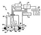
도 1 및 도 2를 참조하면, 본 발명에 따른 유체 질량유량 제어기는 참조부호 "20"으로 나타내었다. 질량유량 제어기(20)는 각각 협력하는 평면(24a, 26a)에서 종래의 기계식 조임장치(28)에 의해 서로 결합되는 직사각형 블록 형상의 제1, 2 본체부(24, 26, a first and second body part)를 포함하는 2개 부분 본체(22, a two-part body)를 포함한다. 제 1, 2 본체부(24, 26)에는 반도체 제조에 사용되는 가스형태의 유독성 또는 반응성 유체를 공급하기 위한 시스템용 도관에 유체 질량유량 제어기를 접속시키기 위한 유체 도관 접속부(25, 27, fluid conduct connector portions)가 제공되어 있다.1 and 2, the fluid mass flow controller according to the present invention is indicated by the reference numeral "20". The
도 2에 도시된 바와 같이, 질량유량 제어기(20)는 텅스텐 헥사플루오라이드, 클로린 또는 설퍼 헥사플루오라이드등과 같은 유체에 압력을 가하기 위한 압력 공급 용기(29)를 포함하는 제조 시스템에 개재될 수 있다. 압력 공급 용기(29)는 도관(30)을 통해 질량유량 제어기(20)에 접속되며, 퍼지 도관(32, a perge coduit)은 상기 도관(30)에 또한 접속되며 필요시 적절한 리시버(receiver) 또는 스크러브(scrubber)(34)로 유제 제어기를 퍼지시키기 위해 도시되지 않은 퍼지 가스 공급원(a source of purge gas)에 접속된다. 그러나, 질량유량 제어기(20)의 작동 동안, 유체의 정확한 유량을 도관(33)을 통해 반도체 제조 챔버(36) 또는 용기내로 도입하기 위해 제어된다. 제조 챔버(36)는 예를 들면 하나 이상의 진공펌프(37)에 의해 실질적으로 감압된 압력으로 유지된다. 도 2에 도시된 바와 같이 유량 제어기가 개재된 시스템은 유량 제어기의 하나의 바람직한 적용을 도시하기 위해 간략하게 도시되어 있다.As shown in FIG. 2, the
도 2를 참조하면, 제1 본체부(24)는 도시되지 않은 종래의 기계식 조임장치에 의해 제1 본체부(24)의 평면부(24b)에 탈착가능하게 장착된 전기 제어 유량 제어밸브(40)를 지지한다. 제어밸브(40)는 제1 본체부(24)의 내부 통로(42)로부터 제 1 본체부(24)의 제 2 내부 통로(44)로 스로틀 유체유동으로 작동가능한 전기작동 폐쇄부재(41)를 포함한다. 또한, 제어밸브(40)는 상기 폐쇄부재(41)용 액추에이터(43)를 포함한다. 액추에이터(43)는 폐쇄부재(41)의 빠른 응답 및 정밀도를 위해 솔레노이드 또는 압전 재료를 사용하는 형태가 바람직하다. 또한 제 1 압력 압력센서(46)가 제1 본체부(24)에 탈착가능하게 장착되어 통로(44)와 연통하는 제1 본체부(24)의 통로(47)와 연통한다. 제 2 압력 센서(48)는 제2 본체부(26)상에 탈착가능하게 장착되어 제조 챔버(36)로 인도되는 도관(33)에 접속되는 통로인 제1 본체부(6)의 길이방향 유로(50)내로 개구하는 통로(49)와 연통한다. 제1, 2 압력 센서(46, 48)는 하니웰 데이터 인스트루먼츠 디비젼사의 상업적으로 이용가능한 형태일 수 있다. 제어 밸브(40)와 제1, 2 압력 센서(46, 48)는 도 1의 질량유량 제어기(20)용의 제거가능한 커버(51)내에 배치될 수 있다.Referring to FIG. 2, the
도 3을 참조하면, 제1 본체부(24)는 본체내에 형성되며 유동 제한장치(56)를 수용하기 위한 통로(44)와 동심을 이루는 원통형 카운터보어(counterbore)(54)를 포함한다. 유동 제한장치(56)는 시일 링(62)사이의 카운터보어(54)에 지지된 관형 어댑터(60)에 장착될 수 있는 관형 슬리브(58)에 지지되어 있다. 따라서, 유동 제한장치(56)는 제1, 2본체부(24, 26)를 분리하는 것에 의해 2개 부분 본체(22)로부터 쉽게 제거될 수 있으며, 그의 지지 슬리브(58)와 함께 유동 제한장치를 제거하고 동일한 유동 특성 또는 선택된 다른 유동 특성의 적절한 제한장치로 유동 제한장치를 교체할 수 있다. 유동 제한장치(56)는 제1, 2 압력 센서(46, 48)에 의해 검지될 수 있는 압력차를 발생시키기에 충분한 유동을 허용하도록 설정된 기공도를 갖는 소결된 금속 원통형 플러그형상 부재를 포함한다. 유동 제한장치(56)는 스테인레스강 또는 소망 기공도와 유동 제한 특성을 제공하도록 적절하게 압축되고 소결된 니켈 입자로 제조될 수 있다. 유량 제어기(20)에서 유동 제한장치(56)는 제어밸브(40)의 하류에 배치된다.Referring to FIG. 3, the
도 1을 참조하면, 유량 제어기(20)는 EEPROM 메모리와 같은 비휘발성 메모리(72)에 작동가능하게 접속된 디지털 신호 압축기로 특정되는 디지털 신호 처리 프로세서를 포함하는 마이크로제어기(70), 전원(74) 및 적절한 밸브 구동회로(76)를 포함하는 제어회로 또는 시스템에 의해 작동된다. 마이크로제어기(70)는 구동기(76)에 의한 폐쇄부재(41)의 동작을 효과적으로 하기 위해 제어밸브(40)에 작동가능하게 접속되어 있다. 또한, 마이크로제어기(70)는 제1, 2 압력 센서(46, 48)에 작동가능하게 접속되어 있으며, 설정된 위치에서 제어기(20)를 통해 유동하는 유체의 온도를 검지하도록 위치될 수 있는 온도센서(78)에 작동가능하게 접속되어 있다. 또한, 마이크로제어기(70)는 다양한 공급원으로부터의 명령신호, 데이터 세트 및 프로그래밍 변경을 수신하기 위한 적절한 인터페이스(80)에 작동가능하게 접속되어 있다.Referring to FIG. 1, the
마이크로제어기(70)는 텍사스 인스트루먼츠 인코퍼레이티드사로부터 이용가능한 TMS320 LF2407 마이크로제어기가 바람직하다. 제1, 2 압력 센서(46, 48)는 자체의 A/D 및 D/A 컨버터를 수행하는 마이크로제어기(70)에 아날로그 입력으로서 14 내지 16비트 분해능(rsolution) 범위로 +/- 0.5볼트에서 작동한다. 다른 아날로그 입력은 온도 센서(78)에 대해 입력되며 12비트 분해능으로 명령 신호를 0 내지 5볼트 설정 포인트 명령 신호 입력이다. 또한, 마이크로제어기(70)는 구동기(76)를 통해 제어밸브(40)의 작동을 제어하기 위한 아날로그 출력 신호를 제공한다. 마이크로제어기(70)와의 통신은 RS4854-유선통신링크 및/또는 CAN(Controller Area Network)를 통해 이루어질 수 있다. 또한, 마이크로제어기(70)는 에뮬레이 션(emulation)과 디벅(debug)용 JTAG 인터페이스 및 프로그래밍용 파워업 부트로더(powerup bootloader)를 지원할 수 있다. 메모리(72)는 적어도 4000바이트의 EEPROM이 바람직하다.The
마이크로제어기(70)는 제1, 2 압력센서(46, 48)를 제어하기 위한 입력과 제어밸브(40)를 제어하기 위한 출력신호 사이에 초당 약 100배의 비율로 실행되는 폐루프 제어함수를 요구한다. 통신은 인터페이스(80)를 통해 실행되며, 제어 루프는 제어 루프 업데이트가 유지될 수 없을 때 메모리(72)에 새로운 데이터를 전송한다.The
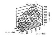
본 발명의 중요한 관점은 질량유량 제어기(20)의 정상 작동 범위를 발견하는 것으로, 유체 유동율은 제조 챔버(36)내의 압력에 실질적으로 대응하는 절대 하류 압력 뿐만 아니라 유동 제한장치(56)를 가로지른 압력차의 함수이다. 도 4는 유동 제한장치(56)를 가로지른 압력차(torr)의 함수 및 유로(50), 도관(33) 및 제조 챔버(36)내의 하류 압력(torr)의 함수로서 분당 표준 세제곱센티미터(SCCM)에서의 유동 특성을 나타낸다. 도 4는 유동 제한장치를 가로질러 유동하는 유체의 유동 특성을 도시하며, 압력 범위는 참조부호 "90"로 나타낸 3차원 면을 가질 수 있다. 유동 특성 또는 면(90)은 특정 온도에 대한 것이다. 도 4에 있어서, 유체에 대한 질량유량 특성(90)은 25℃에서 운영되었다. 도 4에 도시된 바와 같이, 저온에서 취해진 측정은 예를 들면 면(92, 94)으로 나타낸 유동 특성을 제공한다. 면 "92"로 나타낸 유동 특성은 면 "90"으로 나타낸 유동 특성에 대한 온도보다 낮은 온도에 대한 것이며, 상기 측정보다 낮은 온도인 면 "94"에 의해 결정된 유동 특성은 유동 특성 면 "92"를 발전시키기 위해 취해졌다.An important aspect of the present invention is to find the normal operating range of the
또한, 도 4에 도시된 것으로부터, 유동 제한장치를 가로지른 질량유동율, 특히 도 4에 나타낸 압력범위는 하류 압력으로 변화한다. 예를 들면, 하류 압력이 약 0.0torr이고 유체 제한장치를 가로지른 압력차가 약 1575.0torr이면, 특정 제한장치에 대한 유동율은 약 280SCCM이다. 그러나, 하류 압력이 760.0torr(표준 대기압)이면, 유체 제한장치를 가로지른 동일 압력차에 대한 유동율은 약 500SCCM이다. 따라서, 유동 제한장치를 가로지른 가스형태의 유체 유동 거동은 유동 제한장치의 하류 압력 뿐만 아니라 온도 및 압력차에 의존한다.Also, from what is shown in FIG. 4, the mass flow rate across the flow restrictor, in particular the pressure range shown in FIG. 4, changes to the downstream pressure. For example, if the downstream pressure is about 0.0torr and the pressure differential across the fluid restrictor is about 1575.0torr, the flow rate for the particular restrictor is about 280SCCM. However, if the downstream pressure is 760.0torr (standard atmospheric pressure), the flow rate for the same pressure differential across the fluid restrictor is about 500 SCCM. Thus, the gaseous fluid flow behavior across the flow restrictor depends on the temperature and pressure differential as well as the downstream pressure of the flow restrictor.
다양한 온도, 유동 제한장치를 가로지른 압력차 및 하류 압력에서의 도 4에 나타낸 유동 특성은 유동 제한장치(56)와 같은 소결된 금속형 유동 제한장치에 대한 것이다. 선택적으로, 도 6 에 도시된 바와 같은 유사한 유동 특성이 25℃에서의 침상형 원형 오리피스(95)에 대해 나타난다. 도 4 및 도 6에 도시된 특정 유동 특성은 질소가스에 대한 것이지만, 다른 가스도 본 명세서에 기술된 유동 특성의 형태에 대해 도 4 및 도 5에 도시된 일반 유동 특성에 따라 작용하도록 나타난다.The flow characteristics shown in FIG. 4 at various temperatures, pressure differentials across the flow restrictor and downstream pressure are for sintered metal type flow restrictors such as
따라서, 도 4 및 도 6에 따른 유동 특성은 제어기(20)와 같은 질량유량 제어기와 접속되어 사용된 유동 제한장치의 특정 형태 및 반도체 제조에 사용된 처리 가스 또는 증기를 포함하는 액체 및 가스 형태의 다양한 유체에 대해 개발될 수 있다.Thus, the flow characteristics according to FIGS. 4 and 6 are of particular form of flow restrictor used in connection with a mass flow controller such as
도 4의 면 "90, 92, 94"와 같은 3차원 유동 특성을 표시하는 데이터 점은 다양한 방식으로 개발되어 유량 제어기(20)의 메모리(72)내로 도입될 수 있다. 설정 포인트 모드에서 작동될 때 유량 제어기 마이크로제어기(70)는, 유동율이 마이크로제어기로의 명령 입력에 설정 포인트 또는 추적으로서 마이크로제어기(70)내로 프로그 램될 때까지, 실제 유동율을 결정하기 위해 제1, 2 압력 센서(46, 48)에 의해 유동 제한장치를 가로지른 압력차를 검지하는 것에 의해 설정포인트에 접근하도록 유량 제어기(20)를 통한 유동을 조절하기 위해 제어밸브(40)의 작동을 명령하도록 프로그램될 수 있다. 특정 가스에 대해 면 "90, 92, 94"를 나타내는 데이터 포인트는 종래의 유동측정설비를 사용하여 얻어질 수 있다.Data points indicative of three-dimensional flow characteristics, such as planes "90, 92, 94" in FIG. 4 may be developed in various ways and introduced into the
비율 변경 질량유량 측정장치가 데이터 포인트를 얻기위해 또한 사용될 수 있다. 더욱이, 이러한 유동 측정장치는 설계 사양서내의 유량 제어기(20)와 같은 유량 제어기의 작동을 입증하는데 사용될 수 있으며, 또한 설계 사양서내의 특정 유동 제한장치를 입증하는데 사용될 수 있다. 설계 사양서가 본 명세서에 기술된 형태의 유체 제어장치 및 유량 제어기에 대해 설계되면, 각각의 성능은 유독성 및 고반응성 가스가 각각 완성된 유량 제어기 또는 유동 제한장치의 검증 시험동안 사용되는 것이 요구되지 않도록 비율 변경 질량유량 측정장치 또는 질량유량 측정장치 및 불활성가스의 사용이 입증될 수 있다. 예를 들면, 데이터 포인트의 선택된 수는 제어기(20)와 같은 유량 제어기 또는 유동 제한장치(56)와 같은 유동 제한장치에 대해 대기인 배기압으로 30psig 불활성가스에서의 50, 100, 500 및 3,000 SCCM의 유동율에서 입증될 수 있다. 또한, 유량 제어기(20)의 설계 사양서를 나타내는 데이터 포인트는 전술한 비율 변경 유동 측정장치로 시험될 때 유량 제어기의 작동성을 입증하기 위해 메모리(70)내로 도입될 수 있다. 적절한 비율 변경 또는 상승률 질량유량 측정장치가 상업적으로 이용가능하다.Rate-change mass flow meters can also be used to obtain data points. Moreover, such flow measuring devices can be used to verify the operation of a flow controller, such as
더욱이, 유체 질량유량 제어기(20)는 유량 제어기(20)와 동일한 형태의 제어 기와 조합하여 시험된 어떠한 유체에 대한 데이터 공급원에 접속되는 네트워크를 구비한 인터페이스(80)를 통해 접속될 수 있다. 이 방식에 있어서, 유량 제어기(20)에 의해 제어되는 어떠한 가스는 적절한 프로세서에 기억된 데이터베이스를 즉시 조회하는 것에 의해 메모리(70)내로 도입된 그의 유동 특성을 가질 수 있다. 예를 들면, 유량 제어기(20)의 매각인은 폭넓은 가스에 대해 조합된 프로세서 및 메모리상에 기억된 선택된 데이터 세트를 가질 수 있으며, 데이터 세트 형태에 대응하는 각 데이터 세트는 유동 제한장치의 어떠한 한 형태에 대해 도 4 및 도 6에 도시된 유동 특성을 각각 제공할 것이다. 유량 제어기(20)와 같은 유량 제어기를 사용하고 특정 가스로 제어기를 사용하기를 원하는 고객은 예를 들면 인터넷과 같은 네트워크를 통해 마이크로제어기(70)와 그의 메모리(72)로 직접 필요한 데이터 세트를 공급 및 다운로드해줄 것을 즉시 매각인에게 요구할 수 있다.Moreover, the fluid
마이크로제어기(70)의 작동은 도 7 및 도 8를 참조하여 이하에서 상세히 설명한다. 마이크로제어기 또는 프로세서(70)는 폐루프 제어 및 통신 기능을 실행하도록 작동가능하다. 폐루프 제어는 초당 100배의 비율로 실행되는 것이 바람직하며 상향(lookup) 테이블 또는 다항식 계산의 실행을 요구한다. 모든 코드는 "C"로 표기될 것이다. 마이크로제어기 또는 프로세서(70)의 기능은 도 7의 플로우차트에 요약되어 있다. 도 7에서의 단계 100은 프로세서(70)의 키 함수를 구동하기 위한 10 밀리초 인터럽트를 나타낸다. 단계 102에 있어서, 프로세서는 하류 압력 "XD1"의 64개의 샘플과 이들 샘플의 평균을 획득한다. 단계 104에 있어서, 프로세서는 상류 압력 "XD2"의 64개의 샘플과 이들 샘플의 평균을 획득한다. 단계 106은 소프 트웨어 태그 "CV1_SN"으로 나타낸 제어밸브(40)의 제어를 위한 아날로그 출력 신호의 32개의 샘플의 평균이다. 단계 108은 단계 110에서의 0 내지 5볼트 설정 포인트 명령 신호 입력의 32개의 샘플과 단계 112에서의 0 내지 5볼트 아날로그 출력신호의 32개의 샘플을 얻기 위한 신호 모드에서의 프로세서(70)의 작동을 나타낸다. 단계 114는 아날로그 입력이 지면에 쇼트될 때를 나타낸다. 단계 116은 TE1로 나타낸 온도 센서(78)로부터의 신호의 32개의 샘플과 이들 샘플의 평균을 얻는 프로세서를 나타낸다. 단계 118은 신호 입력을 압력, 유동 및 온도의 영어 유닛(English units)으로의 전환을 제공한다. 도 7에서의 단계 120은 도 4의 면 "90, 92, 94"를 사용하는 유동 루틴의 계산의 실행이다. 새로운 프로세서는 단계 122에서 제어 모드로 진행한다.Operation of the
도 8은 예를 들면 각각의 작동 온도에 대해 면 "90, 92, 94"와 같은 3차원 지도의 세트를 사용하여 어떻게 유동 루틴의 계산이 실행되는지를 도시하며, 이에 의해 유동은 유동 제한장치(56)를 가로지른 압력차의 변화, 유통 유로(50)에서의 하류 압력 및 온도 센서(78)에 의해 검지된 온도의 함수로서 계산된다. 유동 설정은 하류 압력의 범위 전체에 걸쳐 이루어지며, 유동율은 유동 제한장치(56)에 대해 얻어진다. 이 데이터 세트는 3차원 곡선의 범위로 고정된다. 3차원 지도는 압력차 "XD2-XD1"로 지도화된 z축상의 유동, x축상의 유동 및 y축상의 방출 또는 하류 압력으로 지도화될 수 있다.Figure 8 shows how the calculation of the flow routine is performed using a set of three-dimensional maps such as planes "90, 92, 94" for each operating temperature, whereby the flow is controlled by the flow restrictor ( It is calculated as a function of the change in the pressure difference across 56, the downstream pressure in the
최고-비트 프로세스는 y축의 다양한 값에서 곡선을 발생시킨다. 대표적으로, x대 z의 곡선은 1, 50, 100, 300, 500 및 700torr와 같은 XD1에 대해 생성될 수 있다. 그 후, 프로세스는 다른 작동 온도에서 반복된다. 그 후, 측정 데이터는 유동 포인트로부터 프로세서에서 사용되는 고정된 포인트 양으로 지도화된다. 이들 테이블은 프로세서로 다운로드되며 유동 계산동안 불러낸다. 도 8에서의 단계 124의 측정 데이터를 얻는 것은 센서(78)에 의해 검지된 온도 상하에 가장 가까운 온도에서의 측정 지도 또는 면을 얻는 것에 의해 실행된다. 단계 126 및 128에서의 유동은 측정 데이터(CAL DATA)에서의 2개의 곡선에 대한 압력차 "XD2-XD1"을 내삽하는 것에 의해 계산된다. 현재 측정 온도에서의 유동은 측정 유동 데이터 포인트 사이에 내삽하는 것에 의해 계산된다. 단계 130 및 132에서 현재 측정 데이터에서의 유동은 XD1 값에 의한 Flow(0)과 Flow(i) 및 Flow(0)와 Flow(1)에 대한 y축 값 사이에 내삽하는 것에 의해 계산된다. 유동은 TE1의 값으로 Flow@Temp(0)과 Flow@Temp(1) 사이에 내삽하는 것에 의해 계산되며 2개의 측정 데이터 세트에 대한 온도가 선택된다.The most-bit process generates curves at various values on the y-axis. Representatively, curves of x vs z can be generated for XD1 such as 1, 50, 100, 300, 500 and 700 torr. Thereafter, the process is repeated at different operating temperatures. The measurement data is then mapped from the floating point to the fixed point amount used in the processor. These tables are downloaded to the processor and recalled during the flow calculation. Obtaining the measurement data of
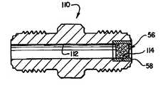
도 5를 참조하면, 전술한 바와 같이 유동 제한장치(56)는 다른 유동 제한장치 및 관련된 장치와 조합하여 작동될 수 있다. 유동 제한장치(56)는 예를 들면 면 시일 접합고정부(110)와 같은 종래의 고정으로 탈착가능하게 장착될 수 있다. 고정부(110)는 원통형 플러그 유동 제한장치(56)와 그의 관형 지지 슬리브(58)를 수용하기 위한 보어(114)를 제공하도록 한쪽 단부에서 카운터보어된 길이방향 관통통로(112)를 포함한다. 슬리브(58)는 보어(114)내에 가벼운 압력으로 고정될 수 있다. 유량 제어기(20)와 조합하여 사용하기 위한 유동 제한장치는 약 0.18인치의 직경과 약 0.18인치의 길이를 갖는 원통형 플러그일 수 있으며, 다공성 소결 스테 인레스강, 니켈 또는 하스텔로이 C-22의 형태일 수 있다. 고체 강 슬리브(58)는 316L 스테인레스강 형태일 수 있다. 유동 제한장치(56)의 제조 허용오차는 예를 들면 30psig의 제한장치의 하류 압력에서 50, 100, 500 및 3,000SCCM의 질량유동율을 입증하는 것에 의해 입증될 것을 요구할 수 있다.Referring to FIG. 5, as described above, the
따라서, 측정 또는 측정 전환 인자는 유동 제한장치(56) 또는 유량 제어기(20)에 대해 필요하지 않다. 사용시, 유량 제어기(20) 및/또는 유동 제한장치(56)는 전술한 비율 변경 유동측정장치 또는 유사한 장치를 사용하는 이들 장치를 통하여 불활성가스의 설정된 양을 유동시키는 것에 의해 작동성을 얻도록 입증될 수 있다. 유동 제한장치 및/또는 유량 제어기는 각각의 장치가 예를 들면 도 4에 도시된 것과 같은 유동 특성에 따라 실행되는 것을 보증하도록 위치되거나 또는 복귀될 수 있다.Thus, no measurement or measurement conversion factor is needed for the
질량유량 제어기(20)와 유동 제한장치(56)의 구성 및 작동 뿐만 아니라 전술한 설정과 같이 유량 제어기의 작동 방법은 본 발명이 속하는 기술분야의 당업자에 의해 쉽게 이해될 것이다. 더욱이, 유량 제어기(20)는 유량계로서 기능하며, 설정 포인트 조건으로 유체 유동율을 제어하기 위한 유량계로서 사용될 수 있다.The construction and operation of the
본 발명의 바람직한 실시예를 기술하였지만, 본 발명이 속하는 기술분야의 당업자에 의해 첨부한 특허청구범위의 기술사상을 일탈하지 않는 범위내에서 다양한 변형 빛 변경이 가능하다.Although preferred embodiments of the present invention have been described, various modifications and changes of light are possible by those skilled in the art to which the present invention pertains without departing from the spirit of the appended claims.
도 1은 본 발명의 유체 질량유량 제어기를 도시하는 개략도;1 is a schematic diagram illustrating a fluid mass flow controller of the present invention;
도 2는 도 1에 도시된 제어기의 종단면도로서 이에 조합된 유체 유동 회로를 도시하는 도면;FIG. 2 is a longitudinal sectional view of the controller shown in FIG. 1 showing a fluid flow circuit combined therewith; FIG.
도 3은 본 발명에 따른 도 1 및 도 2의 유량 제어기에 사용된 유동 제한장치의 상세 단면도;3 is a detailed cross-sectional view of the flow restrictor used in the flow controller of FIGS. 1 and 2 in accordance with the present invention;
도 4는 0torr 내지 2,000torr의 비교적 저압 범위내의 유동 제한장치를 가로지른 압력차와 하류 압력의 함수로서 가스 유체의 질량유동율을 도시하는 도면;4 shows the mass flow rate of gaseous fluid as a function of pressure difference and downstream pressure across a flow restrictor within a relatively low pressure range of 0 tor to 2,000 torr;
도 5는 본 발명에 따른 유동 제한장치와 지지체의 다른 예를 도시하는 종단면도;5 is a longitudinal sectional view showing another example of the flow restrictor and the support according to the present invention;
도 6은 유동 제한장치를 가로지른 압력차와 하류의 압력의 함수로서 유동 제한장치의다른 형태의 특성을 도시하는 도 4의 유사도; 및FIG. 6 is a view similar to FIG. 4 showing other types of characteristics of the flow restrictor as a function of the pressure differential across the flow restrictor and the pressure downstream; And
도 7 및 도 8은 1 및 도 2에 도시된 유체 질량유량 제어기의 조작실행 단계를 도시하는 플로우차트이다.7 and 8 are flowcharts showing the operation execution steps of the fluid mass flow controller shown in Figs.
Claims (4)
Translated fromKoreanApplications Claiming Priority (3)
| Application Number | Priority Date | Filing Date | Title |
|---|---|---|---|
| US09/666,039US6539968B1 (en) | 2000-09-20 | 2000-09-20 | Fluid flow controller and method of operation |
| US09/666,039 | 2000-09-20 | ||
| PCT/US2001/028665WO2002025391A1 (en) | 2000-09-20 | 2001-09-14 | Fluid flow controller and method of operation |
Related Parent Applications (1)
| Application Number | Title | Priority Date | Filing Date |
|---|---|---|---|
| KR1020037003975ADivisionKR100875775B1 (en) | 2000-09-20 | 2001-09-14 | Fluid Mass Flow Controller and Its Operation Method |
Publications (2)
| Publication Number | Publication Date |
|---|---|
| KR20070114857A KR20070114857A (en) | 2007-12-04 |
| KR100875813B1true KR100875813B1 (en) | 2008-12-26 |
Family
ID=24672579
Family Applications (2)
| Application Number | Title | Priority Date | Filing Date |
|---|---|---|---|
| KR1020037003975AExpired - LifetimeKR100875775B1 (en) | 2000-09-20 | 2001-09-14 | Fluid Mass Flow Controller and Its Operation Method |
| KR1020077027614AExpired - Fee RelatedKR100875813B1 (en) | 2000-09-20 | 2001-09-14 | Fluid Mass Flow Controller and Its Operation Method |
Family Applications Before (1)
| Application Number | Title | Priority Date | Filing Date |
|---|---|---|---|
| KR1020037003975AExpired - LifetimeKR100875775B1 (en) | 2000-09-20 | 2001-09-14 | Fluid Mass Flow Controller and Its Operation Method |
Country Status (11)
| Country | Link |
|---|---|
| US (1) | US6539968B1 (en) |
| EP (1) | EP1328854B1 (en) |
| JP (1) | JP4921684B2 (en) |
| KR (2) | KR100875775B1 (en) |
| CN (1) | CN100385359C (en) |
| AT (1) | ATE435448T1 (en) |
| AU (1) | AU2001292651A1 (en) |
| DE (1) | DE60139135D1 (en) |
| MY (1) | MY128274A (en) |
| TW (1) | TW505837B (en) |
| WO (1) | WO2002025391A1 (en) |
Cited By (1)
| Publication number | Priority date | Publication date | Assignee | Title |
|---|---|---|---|---|
| KR101455928B1 (en)* | 2013-04-05 | 2014-10-31 | 배정이 | Mass flow controller with motor driving circuit |
Families Citing this family (128)
| Publication number | Priority date | Publication date | Assignee | Title |
|---|---|---|---|---|
| US6152162A (en) | 1998-10-08 | 2000-11-28 | Mott Metallurgical Corporation | Fluid flow controlling |
| AUPR458201A0 (en)* | 2001-04-23 | 2001-05-24 | Commonwealth Scientific And Industrial Research Organisation | Fluid properties evaluation |
| USRE44943E1 (en)* | 2001-04-23 | 2014-06-10 | Commonwealth Scientific And Industrial Research Organisation | Fluid properties evaluation |
| JP4102564B2 (en)* | 2001-12-28 | 2008-06-18 | 忠弘 大見 | Improved pressure flow controller |
| US6704667B2 (en)* | 2002-05-13 | 2004-03-09 | Taiwan Semiconductor Manufacturing Co., Ltd | Real time mass flow control system with interlock |
| US7552015B2 (en)* | 2002-06-24 | 2009-06-23 | Mks Instruments, Inc. | Apparatus and method for displaying mass flow controller pressure |
| GB2419676B8 (en)* | 2002-06-24 | 2008-09-03 | Mks Instr Inc | Mass flow calibrator |
| US6948508B2 (en)* | 2002-06-24 | 2005-09-27 | Mks Instruments, Inc. | Apparatus and method for self-calibration of mass flow controller |
| US20030234047A1 (en)* | 2002-06-24 | 2003-12-25 | Ali Shajii | Apparatus and method for dual processor mass flow controller |
| US7809473B2 (en) | 2002-06-24 | 2010-10-05 | Mks Instruments, Inc. | Apparatus and method for pressure fluctuation insensitive mass flow control |
| US6868862B2 (en)* | 2002-06-24 | 2005-03-22 | Mks Instruments, Inc. | Apparatus and method for mass flow controller with a plurality of closed loop control code sets |
| US7136767B2 (en)* | 2002-06-24 | 2006-11-14 | Mks Instruments, Inc. | Apparatus and method for calibration of mass flow controller |
| US20030234045A1 (en)* | 2002-06-24 | 2003-12-25 | Ali Shajii | Apparatus and method for mass flow controller with on-line diagnostics |
| US7004191B2 (en)* | 2002-06-24 | 2006-02-28 | Mks Instruments, Inc. | Apparatus and method for mass flow controller with embedded web server |
| US6810308B2 (en) | 2002-06-24 | 2004-10-26 | Mks Instruments, Inc. | Apparatus and method for mass flow controller with network access to diagnostics |
| US6712084B2 (en) | 2002-06-24 | 2004-03-30 | Mks Instruments, Inc. | Apparatus and method for pressure fluctuation insensitive mass flow control |
| US7543595B2 (en)* | 2002-06-28 | 2009-06-09 | Siemens Building Technologies, Inc. | Valve calibration method and apparatus |
| CN100374768C (en)* | 2002-07-19 | 2008-03-12 | 诚实公司 | Liquid flow control apparatus and method |
| KR20050067388A (en)* | 2002-08-28 | 2005-07-01 | 호리바 스텍, 인크. | Higher accuracy pressure based flow controller |
| US6886929B2 (en) | 2002-10-25 | 2005-05-03 | Hewlett-Packard Development Company, L.P. | Techniques for improving pressure sensor shock robustness in fluid containment devices |
| JP4020016B2 (en)* | 2003-05-28 | 2007-12-12 | 株式会社島津製作所 | Gas chromatograph |
| US6955072B2 (en)* | 2003-06-25 | 2005-10-18 | Mks Instruments, Inc. | System and method for in-situ flow verification and calibration |
| KR100418684B1 (en)* | 2003-06-27 | 2004-02-14 | 주식회사 현대교정인증기술원 | Differential pressure type fluid mass flow controller for controlling flow gases used in semiconductor device fabrication |
| KR100418683B1 (en)* | 2003-06-27 | 2004-02-14 | 주식회사 현대교정인증기술원 | Differential pressure type fluid mass flow controller for controlling flow gases used in semiconductor device fabrication |
| US7216019B2 (en)* | 2004-07-08 | 2007-05-08 | Celerity, Inc. | Method and system for a mass flow controller with reduced pressure sensitivity |
| JP2008506116A (en)* | 2004-07-09 | 2008-02-28 | セレリティ・インコーポレイテッド | Method and system for flow measurement and mass flow regulator validation |
| US7412986B2 (en)* | 2004-07-09 | 2008-08-19 | Celerity, Inc. | Method and system for flow measurement and validation of a mass flow controller |
| JP4461329B2 (en)* | 2004-08-31 | 2010-05-12 | 旭有機材工業株式会社 | Fluid control device |
| US20080029174A1 (en)* | 2004-08-31 | 2008-02-07 | Asahi Organic Chemicals Industry Co., Ltd. | Fluid Control Device |
| US7383851B2 (en)* | 2004-10-07 | 2008-06-10 | Eaton Corporation | Closed loop pressure control system and electrically operated pressure control valve with integral pressure sensor and method of making same |
| CN1974025B (en)* | 2004-10-28 | 2010-06-23 | 博奥生物有限公司 | Micro liquid jetting system |
| CN1311913C (en)* | 2004-10-28 | 2007-04-25 | 博奥生物有限公司 | A micro-liquid injection system |
| US7255012B2 (en) | 2004-12-01 | 2007-08-14 | Rosemount Inc. | Process fluid flow device with variable orifice |
| US7150201B2 (en)* | 2004-12-15 | 2006-12-19 | Celerity, Inc. | System and method for measuring flow |
| US7584665B2 (en)* | 2005-01-14 | 2009-09-08 | Kulite Semiconductor Products, Inc. | Combustion transducer apparatus employing pressure restriction means |
| US7201066B1 (en)* | 2005-03-30 | 2007-04-10 | The Board Of Regents For Oklahoma State University | System for automatic tire inflation |
| US7468095B2 (en)* | 2005-05-12 | 2008-12-23 | Perkinelmer Las, Inc. | System for controlling flow into chromatographic column using transfer line impedance |
| JP4856905B2 (en) | 2005-06-27 | 2012-01-18 | 国立大学法人東北大学 | Flow rate variable type flow control device |
| US9383758B2 (en) | 2005-06-27 | 2016-07-05 | Fujikin Incorporated | Flow rate range variable type flow rate control apparatus |
| US9921089B2 (en) | 2005-06-27 | 2018-03-20 | Fujikin Incorporated | Flow rate range variable type flow rate control apparatus |
| JP2007034667A (en)* | 2005-07-27 | 2007-02-08 | Surpass Kogyo Kk | Flow controller, and regulator unit and valve unit used therefor |
| JP4690827B2 (en)* | 2005-08-26 | 2011-06-01 | 株式会社フジキン | Gasket type orifice and pressure type flow control device using the same |
| US7287432B2 (en)* | 2005-11-17 | 2007-10-30 | Rosemount Inc. | Process transmitter with overpressure vent |
| CN100444310C (en)* | 2005-12-07 | 2008-12-17 | 北京北方微电子基地设备工艺研究中心有限责任公司 | Mass flow controller on-line correction method |
| US7753066B2 (en)* | 2006-05-02 | 2010-07-13 | Thermojet Do Brasil Ltda. | Single system for low or high pressure gases control and high or low pressure gases control valve |
| US20070290382A1 (en)* | 2006-06-14 | 2007-12-20 | Marc Laverdiere | Systems and methods for managing heat transfer in a fluid handling device |
| US7726186B2 (en)* | 2006-07-19 | 2010-06-01 | Degree Controls, Inc. | Airflow sensor for filter blockage detection |
| EP2047154B1 (en)* | 2006-08-02 | 2013-06-12 | BorgWarner, Inc. | Egr system and egr valve with integrated pressure sensor |
| JP5029303B2 (en)* | 2006-11-13 | 2012-09-19 | 東京エレクトロン株式会社 | Process gas supply method, process gas supply system, and object processing system |
| US7896045B2 (en) | 2006-11-13 | 2011-03-01 | The Board Of Regents For Oklahoma State University | Apparatus for delivering air through powered axle assemblies |
| US7875109B1 (en)* | 2007-03-08 | 2011-01-25 | A+ Manufacturing, Llc | Integral flow restrictor valve |
| US8006571B2 (en)* | 2007-09-19 | 2011-08-30 | Siemens Industry, Inc. | Air flow measurement |
| US9297150B2 (en) | 2007-10-24 | 2016-03-29 | Michael Edward Klicpera | Water use monitoring apparatus and water damage prevention system |
| US7693606B2 (en)* | 2007-12-21 | 2010-04-06 | Rosemount Inc. | Diagnostics for mass flow control |
| US9288886B2 (en)* | 2008-05-30 | 2016-03-15 | Colorado State University Research Foundation | Plasma-based chemical source device and method of use thereof |
| JP5408916B2 (en)* | 2008-07-08 | 2014-02-05 | サーパス工業株式会社 | Differential pressure flow meter and flow controller |
| JP5220642B2 (en)* | 2009-02-05 | 2013-06-26 | サーパス工業株式会社 | Differential pressure flow meter and flow controller |
| US9605985B2 (en)* | 2009-10-01 | 2017-03-28 | Horiba Stec, Co., Ltd. | Flow rate measuring mechanism, mass flow controller, and pressure sensor |
| WO2011040409A1 (en)* | 2009-10-01 | 2011-04-07 | 株式会社堀場エステック | Flow rate measuring mechanism and mass flow controller |
| TWI435196B (en) | 2009-10-15 | 2014-04-21 | Pivotal Systems Corp | Method and apparatus for gas flow control |
| US8632512B2 (en)* | 2010-04-09 | 2014-01-21 | Kci Licensing, Inc. | Apparatuses, methods, and compositions for the treatment and prophylaxis of chronic wounds |
| SE534897C2 (en)* | 2010-05-17 | 2012-02-07 | Mindray Medical Sweden Ab | Piezoelectric controlled high pressure valve and method for controlling a high pressure valve |
| US20110284779A1 (en)* | 2010-05-18 | 2011-11-24 | Mindray Medical Sweden Ab | Method and apparatus for controlling a high-pressure valve |
| JP5605969B2 (en) | 2011-05-10 | 2014-10-15 | 株式会社フジキン | Pressure type flow rate control device with flow rate monitor, fluid supply system abnormality detection method using the same, and treatment method for monitor flow rate abnormality |
| US9976887B1 (en)* | 2011-06-22 | 2018-05-22 | Daniel T. Mudd | Wider dynamic accuracy range for gas delivery devices |
| JP5755958B2 (en) | 2011-07-08 | 2015-07-29 | 株式会社フジキン | Raw material gas supply equipment for semiconductor manufacturing equipment |
| JP5739261B2 (en)* | 2011-07-28 | 2015-06-24 | 株式会社堀場エステック | Gas supply system |
| US9448564B2 (en)* | 2013-02-15 | 2016-09-20 | Reno Technologies, Inc. | Gas delivery system for outputting fast square waves of process gas during semiconductor processing |
| US9188989B1 (en)* | 2011-08-20 | 2015-11-17 | Daniel T. Mudd | Flow node to deliver process gas using a remote pressure measurement device |
| US9958302B2 (en)* | 2011-08-20 | 2018-05-01 | Reno Technologies, Inc. | Flow control system, method, and apparatus |
| JP5647083B2 (en) | 2011-09-06 | 2014-12-24 | 株式会社フジキン | Raw material vaporization supply device with raw material concentration detection mechanism |
| US11022985B2 (en) | 2011-12-16 | 2021-06-01 | Fluid Handling Llc | Discrete valve flow rate converter |
| WO2014040002A2 (en)* | 2012-09-10 | 2014-03-13 | Mudd Daniel T | Pressure based mass flow controller |
| CN102873007A (en)* | 2012-09-18 | 2013-01-16 | 张家港市盛港绿色防火建材有限公司 | Material feeding device used for plate making machine |
| CN102873747A (en)* | 2012-09-18 | 2013-01-16 | 张家港市盛港绿色防火建材有限公司 | Discharging control device for plate maker |
| CN102984928B (en)* | 2012-12-31 | 2015-11-11 | 西安飞豹科技发展公司 | Airborne small-scale liquid device for cooling |
| US9857805B2 (en) | 2013-02-18 | 2018-01-02 | Flo Technologies, Inc. | Fluid monitoring and control system |
| US10962993B2 (en) | 2013-02-18 | 2021-03-30 | Flo Technologies, Inc. | Manual control for actuated fluid monitoring and control device |
| US11237574B2 (en)* | 2013-02-18 | 2022-02-01 | Flo Technologies, Inc. | Fluid monitoring and control system |
| US9454158B2 (en) | 2013-03-15 | 2016-09-27 | Bhushan Somani | Real time diagnostics for flow controller systems and methods |
| CN104678985B (en)* | 2013-12-03 | 2018-10-09 | 无锡华润华晶微电子有限公司 | A kind of device and method of verification mass flow controller |
| JP2015155845A (en)* | 2014-02-20 | 2015-08-27 | サーパス工業株式会社 | Differential pressure type flowmeter and flow rate controller including the same |
| US20150277447A1 (en)* | 2014-03-28 | 2015-10-01 | Bray International, Inc. | Pressure Independent Control Valve for Small Diameter Flow, Energy Use and/or Transfer |
| CN103859574B (en)* | 2014-03-31 | 2016-02-10 | 西南大学 | A kind of tobacco flue-curing house |
| EP3835629A1 (en) | 2014-04-17 | 2021-06-16 | Compart Systems Pte. Ltd. | Gasket with ultra-sealing effect for joining high purity fluid pathways |
| EP3234723B1 (en)* | 2014-12-15 | 2022-03-23 | Fluid Handling LLC. | A discrete valve flow rate converter |
| US9717455B2 (en)* | 2015-03-31 | 2017-08-01 | Empire Technology Development Llc | Portable flow meter for low volume applications |
| US9904299B2 (en)* | 2015-04-08 | 2018-02-27 | Tokyo Electron Limited | Gas supply control method |
| KR102371907B1 (en)* | 2015-07-10 | 2022-03-08 | 피포탈 시스템즈 코포레이션 | Gas flow control method and device |
| US9980672B2 (en) | 2015-07-16 | 2018-05-29 | Empire Technology Development Llc | Single-chambered sweat rate monitoring sensor |
| JP6651323B2 (en)* | 2015-10-02 | 2020-02-19 | サーパス工業株式会社 | Flow control device |
| CN105333207B (en)* | 2015-12-11 | 2018-08-24 | 中国航空工业集团公司西安飞机设计研究所 | A kind of bleed valve based on flow-rate adjustment |
| US11549837B2 (en) | 2016-02-04 | 2023-01-10 | Michael Edward Klicpera | Water meter and leak detection system |
| CN108780332B (en)* | 2016-02-29 | 2021-10-01 | 株式会社富士金 | Flow rate control device |
| GB2549286B (en) | 2016-04-11 | 2019-07-24 | Perkins Engines Co Ltd | EGR valve with integrated sensor |
| KR102079988B1 (en)* | 2016-04-28 | 2020-02-21 | 가부시키가이샤 후지킨 | Fluid control device, control method of fluid control device, and fluid control system |
| US10838437B2 (en) | 2018-02-22 | 2020-11-17 | Ichor Systems, Inc. | Apparatus for splitting flow of process gas and method of operating same |
| US11144075B2 (en) | 2016-06-30 | 2021-10-12 | Ichor Systems, Inc. | Flow control system, method, and apparatus |
| US10679880B2 (en) | 2016-09-27 | 2020-06-09 | Ichor Systems, Inc. | Method of achieving improved transient response in apparatus for controlling flow and system for accomplishing same |
| US10303189B2 (en) | 2016-06-30 | 2019-05-28 | Reno Technologies, Inc. | Flow control system, method, and apparatus |
| WO2018047644A1 (en)* | 2016-09-12 | 2018-03-15 | 株式会社堀場エステック | Flow ratio control device, program for flow ratio control device, and flow ratio control method |
| US10663337B2 (en) | 2016-12-30 | 2020-05-26 | Ichor Systems, Inc. | Apparatus for controlling flow and method of calibrating same |
| US9785154B2 (en)* | 2017-02-13 | 2017-10-10 | Robert M. McMillan | Reconfigurable modular fluid flow control system for liquids or gases |
| US10983538B2 (en) | 2017-02-27 | 2021-04-20 | Flow Devices And Systems Inc. | Systems and methods for flow sensor back pressure adjustment for mass flow controller |
| WO2019059040A1 (en)* | 2017-09-25 | 2019-03-28 | 株式会社フジキン | Valve device, adjustment information generating method, flow adjustment method, fluid control device, flow control method, semiconductor manufacturing device and semiconductor manufacturing method |
| US10527516B2 (en) | 2017-11-20 | 2020-01-07 | Phyn Llc | Passive leak detection for building water supply |
| US11095960B2 (en) | 2018-03-07 | 2021-08-17 | Michael Edward Klicpera | Water meter and leak detection system having communication with a intelligent central hub listening and speaking apparatus, wireless thermostat and/or home automation system |
| US11105512B2 (en) | 2018-03-30 | 2021-08-31 | Midea Group Co., Ltd | Method and system for controlling a flow curve of an electromechanical gas valve |
| JP2021536577A (en) | 2018-09-18 | 2021-12-27 | スウェージロック カンパニー | Fluid monitoring module structure |
| WO2020061127A1 (en) | 2018-09-19 | 2020-03-26 | Swagelok Company | Flow restricting fluid component |
| US11280651B2 (en) | 2019-03-25 | 2022-03-22 | Flo Technologies, Inc. | Thin film thermal mass flow sensor in fluid applications |
| KR20250057125A (en)* | 2019-04-15 | 2025-04-28 | 램 리써치 코포레이션 | Modular-component system for gas delivery |
| US11914407B2 (en)* | 2019-04-25 | 2024-02-27 | Fujikin Incorporated | Flow rate control device |
| US11624636B2 (en) | 2019-05-07 | 2023-04-11 | Fortune Brands Water Innovations LLC | Turbine design for flow meter |
| WO2021026222A1 (en)* | 2019-08-05 | 2021-02-11 | Ichor Systems, Inc. | Seal for a flow restrictor |
| US11841036B2 (en) | 2019-08-05 | 2023-12-12 | Ichor Systems, Inc. | Laminar flow restrictor and seal for same |
| TWI723489B (en)* | 2019-08-12 | 2021-04-01 | 鐳鋌科技有限公司 | Gas scrubber energy-saving control device |
| CN110500443B (en)* | 2019-08-26 | 2020-11-06 | 赵国栋 | Proportional pressure reducing valve capable of monitoring fluid speed before and after valve |
| US12334355B2 (en)* | 2019-12-25 | 2025-06-17 | Fujikin Incorporated | Pressure control device |
| US12181328B2 (en)* | 2020-04-17 | 2024-12-31 | Illinois Tool Works Inc. | Flow through pressure sensor structured to remove dead volume |
| US11262069B2 (en) | 2020-06-25 | 2022-03-01 | Midea Group Co., Ltd. | Method and system for auto-adjusting an active range of a gas cooking appliance |
| US11899477B2 (en) | 2021-03-03 | 2024-02-13 | Ichor Systems, Inc. | Fluid flow control system comprising a manifold assembly |
| US12085964B2 (en)* | 2021-12-03 | 2024-09-10 | Goodrich Corporation | Smart pressure regulator for emergency evacuation inflation system |
| US12000723B2 (en) | 2022-02-18 | 2024-06-04 | Mks Instruments, Inc. | Method and apparatus for pressure based mass flow control |
| US12029172B1 (en) | 2023-01-07 | 2024-07-09 | Lumo, Inc. | Water control device for agriculture |
| US12436049B2 (en) | 2023-02-16 | 2025-10-07 | Te Connectivity Solutions Gmbh | Sensor die with a diaphragm |
| US20240281007A1 (en)* | 2023-02-17 | 2024-08-22 | Mks Instruments, Inc. | Method and Apparatus for Integrated Pressure and Flow Controller |
| US12405184B1 (en) | 2023-11-22 | 2025-09-02 | Michael Edward Klicpera | Water meter and leak detection system |
Citations (3)
| Publication number | Priority date | Publication date | Assignee | Title |
|---|---|---|---|---|
| US3570807A (en) | 1969-01-14 | 1971-03-16 | Bell Aerospace Corp | Electromechanical control valve |
| US3841520A (en) | 1969-04-04 | 1974-10-15 | Airco Inc | Flame arresting vent valve |
| US4014626A (en) | 1975-09-08 | 1977-03-29 | Grenn James F | Centrifugal pump means |
Family Cites Families (84)
| Publication number | Priority date | Publication date | Assignee | Title |
|---|---|---|---|---|
| US2666297A (en) | 1950-03-14 | 1954-01-19 | Elmer C Skousgaard | Container and discharge valve therefor |
| US3335748A (en) | 1964-09-15 | 1967-08-15 | Henry B Peter | Adjustable control for metered flow |
| US3271994A (en) | 1965-04-19 | 1966-09-13 | Jered Ind Inc | Fluid flow comparator for use in calibrating fluid flow orifices |
| US3559482A (en) | 1968-11-27 | 1971-02-02 | Teledyne Inc | Fluid flow measuring apparatus |
| US3807456A (en) | 1970-06-25 | 1974-04-30 | Trw Inc | Hydraulic controller including rotary valve |
| US3814541A (en) | 1971-11-24 | 1974-06-04 | Delta Controls Ltd | Fluid supply apparatus |
| US3910113A (en) | 1972-11-20 | 1975-10-07 | William R Brown | Method of selectively varying the differential output and overall performance characteristics of a proportional differential pressure producing fluid flow device |
| US4026657A (en) | 1974-09-05 | 1977-05-31 | Textron, Inc. | Sintered spherical articles |
| US4015626A (en) | 1976-01-22 | 1977-04-05 | Thordarson, Inc. | Constant flow valve for low flow rates |
| US4096746A (en) | 1977-02-25 | 1978-06-27 | The Perkin-Elmer Corporation | Flow controller-flow sensor assembly for gas chromatographs and the like |
| US4275752A (en) | 1978-09-22 | 1981-06-30 | Collier Nigel A | Fluid flow apparatus and method |
| US4203465A (en) | 1979-03-27 | 1980-05-20 | General Motors Corporation | Precision pressure control valve |
| US4253156A (en) | 1979-06-22 | 1981-02-24 | The United States Of America As Represented By The Administrator Of The National Aeronautics And Space Administration | Automatic flowmeter calibration system |
| DE2929389C2 (en) | 1979-07-20 | 1984-05-17 | Machinefabriek Mokveld B.V., 2800 Gouda | Control valve |
| US4315523A (en) | 1980-03-06 | 1982-02-16 | American Flow Systems, Inc. | Electronically controlled flow meter and flow control system |
| EP0061856B1 (en)* | 1981-04-01 | 1987-08-26 | LUCAS INDUSTRIES public limited company | Measurement of air mass flow into an internal combustion engine |
| US4462915A (en) | 1981-09-23 | 1984-07-31 | Oil Process Systems, Inc. | Method and system for filtering cooking oil |
| AT381571B (en) | 1982-11-15 | 1986-11-10 | Oemv Ag | DEVICE FOR STAGE PRESSURE RELEASE WHEN RELAXING, IN PARTICULAR, HOT GASES |
| FR2543321B1 (en) | 1983-03-22 | 1985-08-16 | Electricite De France | DEVICE FOR CONTROLLING A FLOW OF FLUID, ESPECIALLY RADIOACTIVE FLUID |
| US4576043A (en) | 1984-05-17 | 1986-03-18 | Chevron Research Company | Methods for metering two-phase flow |
| US4687020A (en) | 1985-05-17 | 1987-08-18 | Doyle James H | Fluid mass flow controller |
| US4669052A (en) | 1985-07-02 | 1987-05-26 | Motorola, Inc. | Apparatus and method for calibrating a sensor |
| DE3538828A1 (en) | 1985-10-31 | 1987-05-07 | Druva Gmbh | BASIC FITTINGS, PARTICULARLY AS PART OF A PRESSURE REDUCER |
| US4718443A (en) | 1987-02-06 | 1988-01-12 | Conoco Inc. | Mass flowmeter apparatus |
| US5100551A (en) | 1987-03-27 | 1992-03-31 | Pall Corporation | Segmented filter disc with slotted support and drainage plate |
| GB8711931D0 (en) | 1987-05-20 | 1987-06-24 | British Petroleum Co Plc | Filtration/coalescence |
| CA1309954C (en) | 1987-07-29 | 1992-11-10 | Yasuo Yamada | Deaerator for particulates |
| GB8720356D0 (en) | 1987-08-28 | 1987-10-07 | Thorn Emi Flow Measurement Ltd | Fluid meter |
| US4918995A (en) | 1988-01-04 | 1990-04-24 | Gas Research Institute | Electronic gas meter |
| US4858643A (en) | 1988-03-14 | 1989-08-22 | Unit Instruments, Inc. | Fluid flow stabilizing apparatus |
| US4796651A (en) | 1988-03-30 | 1989-01-10 | LeRoy D. Ginn | Variable gas volume flow measuring and control methods and apparatus |
| NL9000339A (en) | 1990-02-13 | 1991-09-02 | System Engineering & Component | PRESSURE DROP REDUCTION DEVICE, AND VALVE FITTED WITH A PRESSURE DROP REDUCTION DEVICE. |
| US5419133A (en) | 1989-09-05 | 1995-05-30 | Schneider; Edward T. | High speed thermochemical actuator |
| US5080131A (en) | 1989-09-26 | 1992-01-14 | Lintec Co., Ltd. | Mass flow controller |
| DE3936619A1 (en) | 1989-11-03 | 1991-05-08 | Man Nutzfahrzeuge Ag | METHOD FOR INJECTING A FUEL INTO THE COMBUSTION CHAMBER OF AN AIR COMPRESSING, SELF-IGNITION ENGINE, AND APPARATUS FOR CARRYING OUT THIS METHOD |
| JPH03156509A (en) | 1989-11-14 | 1991-07-04 | Stec Kk | Mass flow controller |
| US5142483A (en) | 1990-04-24 | 1992-08-25 | Caltechnix Corporation | Pressure regulating system for positive shut-off pressure controller |
| US5237523A (en) | 1990-07-25 | 1993-08-17 | Honeywell Inc. | Flowmeter fluid composition and temperature correction |
| US5100100A (en) | 1990-09-12 | 1992-03-31 | Mks Instruments, Inc. | Fluid control and shut off valve |
| US5052363A (en) | 1990-10-22 | 1991-10-01 | Ford Motor Company | EGR control valve having ceramic elements |
| US5138869A (en) | 1990-12-14 | 1992-08-18 | Novapure Corporation | In-line detector system for real-time determination of impurity concentration in a flowing gas stream |
| US5583282A (en) | 1990-12-14 | 1996-12-10 | Millipore Investment Holdings Limited | Differential gas sensing in-line monitoring system |
| US5062446A (en) | 1991-01-07 | 1991-11-05 | Sematech, Inc. | Intelligent mass flow controller |
| JPH07111367B2 (en) | 1991-02-26 | 1995-11-29 | ディーエクスエル・インターナショナル・インコーポレーテッド | Flow rate sensor and its inspection method |
| US5359878A (en) | 1991-02-26 | 1994-11-01 | Dxl International, Inc. | Apparatus and method for in-line calibration verification of mass flow meters |
| US5114447A (en) | 1991-03-12 | 1992-05-19 | Mott Metallurgical Corporation | Ultra-high efficiency porous metal filter |
| DK0584242T3 (en) | 1991-05-17 | 1996-07-22 | Unit Instr Inc | Apparatus for calibrating a flow control device |
| US5146941A (en)* | 1991-09-12 | 1992-09-15 | Unitech Development Corp. | High turndown mass flow control system for regulating gas flow to a variable pressure system |
| JP3182807B2 (en)* | 1991-09-20 | 2001-07-03 | 株式会社日立製作所 | Multifunctional fluid measurement transmission device and fluid volume measurement control system using the same |
| US5311762A (en) | 1991-12-16 | 1994-05-17 | Dxl Usa | Flow sensor calibration |
| EP0547617B1 (en) | 1991-12-18 | 1996-07-10 | Pierre Delajoud | Mass flow meter and method |
| US5187972A (en) | 1992-01-17 | 1993-02-23 | Clean Air Engineering, Inc. | Gas monitor |
| US5190068A (en) | 1992-07-02 | 1993-03-02 | Brian Philbin | Control apparatus and method for controlling fluid flows and pressures |
| US5297427A (en) | 1992-09-03 | 1994-03-29 | Alicat Scientific, Inc. | Wide-range laminar flowmeter |
| JPH06138951A (en)* | 1992-10-26 | 1994-05-20 | Toyota Central Res & Dev Lab Inc | Gas mass flow rate controller |
| US5329966A (en) | 1993-03-08 | 1994-07-19 | Vici Metronics Incorporated | Gas flow controller |
| DE69401031T2 (en) | 1993-06-04 | 1997-04-30 | Millipore Corp | Metal filter element with high efficiency and process for its production |
| AU1435195A (en)* | 1993-12-23 | 1995-07-10 | Honeywell Inc. | Flow sensor package having dual integrated restrictors |
| US5511585A (en) | 1994-03-31 | 1996-04-30 | The Lee Company | Method and device for providing fluid resistance within a flow passageway |
| US5624409A (en) | 1994-06-10 | 1997-04-29 | Fluidsense Corporation | Variable-pulse dynamic fluid flow controller |
| US5730181A (en) | 1994-07-15 | 1998-03-24 | Unit Instruments, Inc. | Mass flow controller with vertical purifier |
| US5549272A (en) | 1994-08-11 | 1996-08-27 | Johnson Service Company | Combination pressure pulsation damper and check valve depressor |
| JPH0863235A (en)* | 1994-08-24 | 1996-03-08 | Burutsukusu Instr Kk | Differential pressure type mass flow rate control unit |
| US5542284A (en) | 1994-10-18 | 1996-08-06 | Queen's University At Kingston | Method and instrument for measuring differential oxygen concentration between two flowing gas streams |
| US5660207A (en) | 1994-12-29 | 1997-08-26 | Tylan General, Inc. | Flow controller, parts of flow controller, and related method |
| JP2837112B2 (en)* | 1995-06-09 | 1998-12-14 | 株式会社平井 | Mass flow control method and apparatus using sonic nozzle |
| JPH0961208A (en)* | 1995-08-29 | 1997-03-07 | Oval Corp | Laminar flowmeter |
| US6026847A (en) | 1995-10-11 | 2000-02-22 | Reinicke; Robert H. | Magnetostrictively actuated valve |
| US5804717A (en) | 1996-04-05 | 1998-09-08 | Mks Instruments, Inc. | Mass flow transducer having extended flow rate measurement range |
| CN2243092Y (en)* | 1996-05-10 | 1996-12-18 | 北京圣业科技发展有限公司 | Gas mass flow controller |
| US5868159A (en) | 1996-07-12 | 1999-02-09 | Mks Instruments, Inc. | Pressure-based mass flow controller |
| JP3580645B2 (en)* | 1996-08-12 | 2004-10-27 | 忠弘 大見 | Pressure type flow controller |
| US5944048A (en) | 1996-10-04 | 1999-08-31 | Emerson Electric Co. | Method and apparatus for detecting and controlling mass flow |
| US5911238A (en) | 1996-10-04 | 1999-06-15 | Emerson Electric Co. | Thermal mass flowmeter and mass flow controller, flowmetering system and method |
| US5918616A (en) | 1996-11-15 | 1999-07-06 | Sanfilippo; James J. | Apparatus and method of controlling gas flow |
| US5865205A (en) | 1997-04-17 | 1999-02-02 | Applied Materials, Inc. | Dynamic gas flow controller |
| US5904170A (en) | 1997-05-14 | 1999-05-18 | Applied Materials, Inc. | Pressure flow and concentration control of oxygen/ozone gas mixtures |
| US5917066A (en) | 1997-07-16 | 1999-06-29 | Mott Metallurgical Corporation | Inline ultra-high efficiency filter |
| US5970801A (en)* | 1997-12-30 | 1999-10-26 | Bear Medical Systems, Inc. | Variable orifice flow sensor |
| US6080219A (en) | 1998-05-08 | 2000-06-27 | Mott Metallurgical Corporation | Composite porous media |
| US5988211A (en) | 1998-07-06 | 1999-11-23 | Randolph W. Cornell | I.V. flow controller |
| JP2000163134A (en)* | 1998-09-24 | 2000-06-16 | Aisin Seiki Co Ltd | Flow control valve and fuel cell system |
| US6152162A (en)* | 1998-10-08 | 2000-11-28 | Mott Metallurgical Corporation | Fluid flow controlling |
| US6119710A (en) | 1999-05-26 | 2000-09-19 | Cyber Instrument Technologies Llc | Method for wide range gas flow system with real time flow measurement and correction |
- 2000
- 2000-09-20USUS09/666,039patent/US6539968B1/ennot_activeExpired - Lifetime
- 2001
- 2001-09-14KRKR1020037003975Apatent/KR100875775B1/ennot_activeExpired - Lifetime
- 2001-09-14KRKR1020077027614Apatent/KR100875813B1/ennot_activeExpired - Fee Related
- 2001-09-14JPJP2002529328Apatent/JP4921684B2/ennot_activeExpired - Lifetime
- 2001-09-14WOPCT/US2001/028665patent/WO2002025391A1/enactiveApplication Filing
- 2001-09-14ATAT01973028Tpatent/ATE435448T1/ennot_activeIP Right Cessation
- 2001-09-14CNCNB018159877Apatent/CN100385359C/ennot_activeExpired - Lifetime
- 2001-09-14DEDE60139135Tpatent/DE60139135D1/ennot_activeExpired - Lifetime
- 2001-09-14EPEP01973028Apatent/EP1328854B1/ennot_activeExpired - Lifetime
- 2001-09-14AUAU2001292651Apatent/AU2001292651A1/ennot_activeAbandoned
- 2001-09-19MYMYPI20014379Apatent/MY128274A/enunknown
- 2001-09-20TWTW090123230Apatent/TW505837B/ennot_activeIP Right Cessation
Patent Citations (3)
| Publication number | Priority date | Publication date | Assignee | Title |
|---|---|---|---|---|
| US3570807A (en) | 1969-01-14 | 1971-03-16 | Bell Aerospace Corp | Electromechanical control valve |
| US3841520A (en) | 1969-04-04 | 1974-10-15 | Airco Inc | Flame arresting vent valve |
| US4014626A (en) | 1975-09-08 | 1977-03-29 | Grenn James F | Centrifugal pump means |
Cited By (1)
| Publication number | Priority date | Publication date | Assignee | Title |
|---|---|---|---|---|
| KR101455928B1 (en)* | 2013-04-05 | 2014-10-31 | 배정이 | Mass flow controller with motor driving circuit |
Also Published As
| Publication number | Publication date |
|---|---|
| TW505837B (en) | 2002-10-11 |
| KR20070114857A (en) | 2007-12-04 |
| AU2001292651A1 (en) | 2002-04-02 |
| JP2004510225A (en) | 2004-04-02 |
| EP1328854A1 (en) | 2003-07-23 |
| EP1328854A4 (en) | 2005-01-19 |
| KR100875775B1 (en) | 2008-12-24 |
| KR20030040473A (en) | 2003-05-22 |
| WO2002025391A1 (en) | 2002-03-28 |
| DE60139135D1 (en) | 2009-08-13 |
| MY128274A (en) | 2007-01-31 |
| JP4921684B2 (en) | 2012-04-25 |
| EP1328854B1 (en) | 2009-07-01 |
| ATE435448T1 (en) | 2009-07-15 |
| US6539968B1 (en) | 2003-04-01 |
| CN100385359C (en) | 2008-04-30 |
| CN1461429A (en) | 2003-12-10 |
Similar Documents
| Publication | Publication Date | Title |
|---|---|---|
| KR100875813B1 (en) | Fluid Mass Flow Controller and Its Operation Method | |
| KR100937726B1 (en) | System and method for making and using a mass flow device | |
| US6631334B2 (en) | Pressure-based mass flow controller system | |
| CN104704434B (en) | Method and apparatus for self-calibration of pressure-type mass flow controllers | |
| US6216726B1 (en) | Wide range gas flow system with real time flow measurement and correction | |
| US9870006B2 (en) | Pressure type flow control system with flow monitoring | |
| JP4788920B2 (en) | Mass flow control device, verification method thereof, and semiconductor manufacturing device | |
| US6164116A (en) | Gas module valve automated test fixture | |
| JP4594728B2 (en) | Flow controller based on higher accuracy pressure | |
| CN101563663B (en) | Verification method of flow control device | |
| TWI503525B (en) | Mass flow meter, mass flow controller, and mass flow meter system and mass flow controller system having the same controller | |
| US6074691A (en) | Method for monitoring the flow of a gas into a vacuum reactor | |
| US5261452A (en) | Critical orifice dilution system and method | |
| JP2015509250A (en) | System and method for real-time monitoring of flow through a mass flow controller | |
| WO2002016885A1 (en) | Fluid mass flow meter with substantial measurement range | |
| JP4623806B2 (en) | Flow meter calibration device | |
| JP2013232101A (en) | Gas distributary supply device for semiconductor manufacturing device | |
| US11550341B2 (en) | Mass flow control system, and semiconductor manufacturing equipment and vaporizer including the system | |
| HK1061281A (en) | Fluid flow controller and method of operation |
Legal Events
| Date | Code | Title | Description |
|---|---|---|---|
| A107 | Divisional application of patent | ||
| A201 | Request for examination | ||
| PA0104 | Divisional application for international application | St.27 status event code:A-0-1-A10-A16-div-PA0104 St.27 status event code:A-0-1-A10-A18-div-PA0104 | |
| PA0201 | Request for examination | St.27 status event code:A-1-2-D10-D11-exm-PA0201 | |
| PG1501 | Laying open of application | St.27 status event code:A-1-1-Q10-Q12-nap-PG1501 | |
| E902 | Notification of reason for refusal | ||
| PE0902 | Notice of grounds for rejection | St.27 status event code:A-1-2-D10-D21-exm-PE0902 | |
| AMND | Amendment | ||
| P11-X000 | Amendment of application requested | St.27 status event code:A-2-2-P10-P11-nap-X000 | |
| P13-X000 | Application amended | St.27 status event code:A-2-2-P10-P13-nap-X000 | |
| E601 | Decision to refuse application | ||
| PE0601 | Decision on rejection of patent | St.27 status event code:N-2-6-B10-B15-exm-PE0601 | |
| AMND | Amendment | ||
| J201 | Request for trial against refusal decision | ||
| P11-X000 | Amendment of application requested | St.27 status event code:A-2-2-P10-P11-nap-X000 | |
| P13-X000 | Application amended | St.27 status event code:A-2-2-P10-P13-nap-X000 | |
| PJ0201 | Trial against decision of rejection | St.27 status event code:A-3-3-V10-V11-apl-PJ0201 | |
| R18-X000 | Changes to party contact information recorded | St.27 status event code:A-3-3-R10-R18-oth-X000 | |
| R18-X000 | Changes to party contact information recorded | St.27 status event code:A-3-3-R10-R18-oth-X000 | |
| PB0901 | Examination by re-examination before a trial | St.27 status event code:A-6-3-E10-E12-rex-PB0901 | |
| B701 | Decision to grant | ||
| PB0701 | Decision of registration after re-examination before a trial | St.27 status event code:A-3-4-F10-F13-rex-PB0701 | |
| GRNT | Written decision to grant | ||
| PR0701 | Registration of establishment | St.27 status event code:A-2-4-F10-F11-exm-PR0701 | |
| PR1002 | Payment of registration fee | Fee payment year number:1 St.27 status event code:A-2-2-U10-U12-oth-PR1002 | |
| PG1601 | Publication of registration | St.27 status event code:A-4-4-Q10-Q13-nap-PG1601 | |
| FPAY | Annual fee payment | Payment date:20111229 Year of fee payment:4 | |
| PR1001 | Payment of annual fee | Fee payment year number:4 St.27 status event code:A-4-4-U10-U11-oth-PR1001 | |
| LAPS | Lapse due to unpaid annual fee | ||
| PC1903 | Unpaid annual fee | Not in force date:20121218 Payment event data comment text:Termination Category : DEFAULT_OF_REGISTRATION_FEE St.27 status event code:A-4-4-U10-U13-oth-PC1903 | |
| PC1903 | Unpaid annual fee | Ip right cessation event data comment text:Termination Category : DEFAULT_OF_REGISTRATION_FEE Not in force date:20121218 St.27 status event code:N-4-6-H10-H13-oth-PC1903 | |
| R18-X000 | Changes to party contact information recorded | St.27 status event code:A-5-5-R10-R18-oth-X000 |