KR100875504B1 - Perlite Carbon Ground Module - Google Patents
Perlite Carbon Ground ModuleDownload PDFInfo
- Publication number
- KR100875504B1 KR100875504B1KR1020080073129AKR20080073129AKR100875504B1KR 100875504 B1KR100875504 B1KR 100875504B1KR 1020080073129 AKR1020080073129 AKR 1020080073129AKR 20080073129 AKR20080073129 AKR 20080073129AKR 100875504 B1KR100875504 B1KR 100875504B1
- Authority
- KR
- South Korea
- Prior art keywords
- perlite
- grounding
- ground
- grounding body
- carbon
- Prior art date
- Legal status (The legal status is an assumption and is not a legal conclusion. Google has not performed a legal analysis and makes no representation as to the accuracy of the status listed.)
- Expired - Fee Related
Links
Images


Classifications
- H—ELECTRICITY
- H01—ELECTRIC ELEMENTS
- H01R—ELECTRICALLY-CONDUCTIVE CONNECTIONS; STRUCTURAL ASSOCIATIONS OF A PLURALITY OF MUTUALLY-INSULATED ELECTRICAL CONNECTING ELEMENTS; COUPLING DEVICES; CURRENT COLLECTORS
- H01R4/00—Electrically-conductive connections between two or more conductive members in direct contact, i.e. touching one another; Means for effecting or maintaining such contact; Electrically-conductive connections having two or more spaced connecting locations for conductors and using contact members penetrating insulation
- H01R4/58—Electrically-conductive connections between two or more conductive members in direct contact, i.e. touching one another; Means for effecting or maintaining such contact; Electrically-conductive connections having two or more spaced connecting locations for conductors and using contact members penetrating insulation characterised by the form or material of the contacting members
- H01R4/66—Connections with the terrestrial mass, e.g. earth plate, earth pin
Landscapes
- Manufacturing Of Electrical Connectors (AREA)
Abstract
Translated fromKoreanDescription
Translated fromKorean본 발명은 접지 장치에 사용되는 퍼라이트 탄소 접지 모듈에 관한 것으로서, 더욱 상세하게는 과도임피던스 특성 및 낮은 저항값을 유지함과 동시에 그 접지 모듈이 매설된 대지와의 저항을 단계화시킴으로서 뇌서지 등 사고전류의 파동임피던스 특성을 개선시킨 퍼라이트 탄소 접지 모듈에 관한 것이다.The present invention relates to a perlite carbon grounding module used in a grounding device, and more particularly, to maintain a transient impedance and a low resistance value, and at the same time stage the resistance of the grounding module embedded therein, such as a surge surge, etc. The present invention relates to a perlite carbon grounding module with improved wave impedance characteristics.
일반적으로 접지 장치(grounding device)는 통신 장비, 전자 계측 장비, 피뢰 장치 및 전력 장비 등을 전기적으로 대지와 연결시켜 장비에 작용하는 과부하나 낙뢰 등에 의한 서지 전압을 지상으로 흘려 보낼 수 있도록 하는 장치를 말하며, 그 대표적인 예로 구리 접지봉(Copper grounding rod)을 들 수 있다.In general, a grounding device is a device that electrically connects communication equipment, electronic measuring equipment, lightning arresters, and power equipment with the ground to send a surge voltage caused by an overload or lightning strike on the equipment. The representative example is a copper grounding rod.
이러한 접지 장치(이하, 접지봉을 일예로 설명한다.)는 돌침부, 피뢰도선 및 접지 전극을 피뢰 도선으로 연결함으로써 접지 기능을 수행하게 된다. 따라서, 접지 전극은 돌침부에 작용하는 전기적 부하를 신속하게 대지로 방전하기 위하여 항상 낮은 저항과 낮은 과도임피던스 특성을 유지할 것이 요구된다.The grounding device (hereinafter, the grounding rod will be described as an example) performs a grounding function by connecting the protrusion, the lightning conductor, and the ground electrode with the lightning conductor. Therefore, the ground electrode is required to maintain low resistance and low transient impedance at all times in order to quickly discharge the electrical load acting on the protrusion to the ground.
이를 위하여 종래에는 본 발명의 출원인이 출원한 한국등록특허 제10-0610604호에 개시된 바와 같이 전기 전도성이 우수한 흑연 등의 탄소계 비금속 광 물과 전해질로 구성된 저 저항체 내부에 금속재 심봉이 박힌 형태의 탄소접지모듈을 사용하였다.To this end, conventionally, as disclosed in Korean Patent No. 10-0610604 filed by the applicant of the present invention, carbon having a metal core rod embedded in a low resistance body composed of an electrolyte and a carbon-based nonmetallic mineral such as graphite having excellent electrical conductivity Grounding module was used.
한편, 낙뢰를 형성하는 뇌운의 경우, 계절에 따라 예를 들면, 하절기에 (-)전하를 과도하게 포함하거나 동절기에 (+)전하를 과도하게 포함하게 된다. 이와 같이 낙뢰가 발생할 경우 종래의 탄소 접지 모듈은 전기 전도성이 우수하기 때문에 하절기에는 뇌운의 (-)전하를 급격하게 대지로 유입시키고, 동절기에는 대지의 (-)전하를 뇌운으로 급격하게 유출시킨다.On the other hand, in the case of a thundercloud forming a lightning strike, depending on the season, for example, excessive (+) charge in the summer or excessive (+) charge in the winter. As such, when a lightning strike occurs, the conventional carbon grounding module has excellent electrical conductivity, so that the negative charges of thunderclouds rapidly flow into the earth during the summer, and the negative charges of the earth rapidly flow into the thunderclouds during the winter season.
이때 종래의 탄소접지모듈은 흑연 소재 등을 사용하여 낮은 접지저항을 유지하여 구리동봉보다는 뛰어난 접지특성으로 서지전압을 대지로 신속히 전달할 수 있었으나 탄소접지모듈과 대지와의 급격한 저항 차이로 서지진행파가 대지로 진행되는 것에 장애가 있었다.In this case, the conventional carbon grounding module maintains low grounding resistance by using graphite materials, so that the surge voltage can be quickly transferred to the ground with better grounding characteristics than copper rods, but the surge progression wave is caused by the rapid resistance difference between the carbon grounding module and the ground. There was an obstacle to going on.
이러한 장애는 접지저항치가 낮더라도 뇌서지 진행파의 흐름을 방해하여 역서지 전압이 발생되는 원인이 된다.Such a disturbance may cause the surge voltage to be generated by interrupting the flow of the surge surge wave even if the ground resistance value is low.
본 발명은 상술한 바와 같은 종래 기술의 문제점을 해결하기 위한 것으로서, 낙뢰와 같은 서지 전압을 신속하게 대지로 전달함과 동시에 방전시킬 수 있는 퍼라이트 탄소 접지 모듈을 제공하는 것을 목적으로 한다.The present invention is to solve the problems of the prior art as described above, it is an object of the present invention to provide a perlite carbon grounding module capable of discharging at the same time as quickly transmitting a surge voltage such as lightning.
본 발명의 일 관점을 따르면, 전도성 금속재의 심봉, 상기 심봉이 그 내부에 일체로 형성되며 저저항 성분을 포함하는 제1 접지체 및 상기 제1 접지체의 외부에 일체로 형성되고 제2 접지체를 포함하며, 상기 제2 접지체의 저항값이 상기 제1 접지체의 저항값보다 큰 것을 특징으로 하는 퍼라이트 탄소 접지 모듈이 제공된다.According to an aspect of the present invention, a mandrel of a conductive metal material, the mandrel is formed integrally therein, and includes a low resistance component and a first grounding body integrally formed outside of the first grounding body, and a second grounding body. And a resistance value of the second grounding body is greater than a resistance value of the first grounding body.
상기 제2 접지체의 외부에는 크랙을 방지하는 탄소 섬유 시트가 더 포함될 수 있다.An outer side of the second grounding body may further include a carbon fiber sheet to prevent cracking.
상기 제1 접지체는 흑연과 타르(tar)로 이루어질 수 있으며, 예컨대, 83%의 흑연과 17%의 타르로 이루어질 수 있다.The first grounding body may be made of graphite and tar, for example, 83% graphite and 17% tar.
제1 접지체는 이건 발명자가 확보하고 있는 등록특허번호 “0610604”호에 제시된 방법 및 구성 성분에 의하여 제조된 접지봉으로 전기 저항이 0Ω에 근접되도록 한 탄소 또는 흑연 금속 분말들을 혼합한 접지체 일 수 있다.The first grounding body is a grounding rod manufactured by the method and components shown in Patent No. “0610604” secured by the inventor, and may be a grounding body mixed with carbon or graphite metal powders having an electrical resistance approaching 0 Ω. have.
상기 제1 접지체는 흑연 및 타르를 주성분으로 할 수 있다.The first grounding body may contain graphite and tar as main components.
상기 제2 접지체는 퍼라이트를 포함할 수 있다.The second ground body may include a ferrite.
상기 제2 접지체는 40wt%의 퍼라이트, 45wt%의 흑연, 10wt%의 도전성 시멘트, 4wt%의 산화철 및 1.0wt%의 은 나노 입자로 이루어질 수 있으며, 상기 퍼라이트, 흑연은 ±5% 범위, 도전성 시멘트는 ±2% 범위, 산화철은 ±0.5% 범위, 은 나노 입자는 ±0.3%범위 내에서 증감이 이루어질 수 있다.The second grounding body may be composed of 40 wt% perlite, 45 wt% graphite, 10 wt% conductive cement, 4 wt% iron oxide, and 1.0 wt% silver nanoparticles. Cement can be increased or decreased within ± 2%, iron oxide ± 0.5%, and silver nanoparticles within ± 0.3%.
또 다르게, 상기 제2 접지체는 47.62wt%의 퍼라이트, 33.33wt%의 흑연, 4.76wt%의 산화철, 4.76wt%의 산화 알루미늄, 9.53wt%의 도전성 시멘트로 이루어질 수 있으며, 상기 퍼라이트, 흑연은 ±5% 범위, 도전성 시멘트는 ±2% 범위, 산화철및 산화 알루미늄은 ±0.5% 범위 내에서 증감이 이루어질 수 있다.Alternatively, the second grounding body may be composed of 47.62 wt% perlite, 33.33 wt% graphite, 4.76 wt% iron oxide, 4.76 wt% aluminum oxide, 9.53 wt% conductive cement. Changes can be made in the range ± 5%, in the range of ± 2% for conductive cement and in the range of ± 0.5% for iron oxide and aluminum oxide.
상술한 바와 같은 퍼라이트 탄소 접지 모듈은 제1 접지체와 제2 접지체의 중량비가 4:1로 이루어지며, 그 비율은 ±10%의 범위 내에서 증감될 수 있다.In the above-described perlite carbon grounding module, the weight ratio of the first grounding body and the second grounding body is 4: 1, and the ratio may be increased or decreased within a range of ± 10%.
본 발명은 탄소 접지 모듈을 이루는 제1 접지체에 의해 낙뢰와 같은 서지 전압이 신속하게 전달되고, 제1 접지체의 외부에 일체로 형성되며 제1 접지체 보다 큰 저항을 가지는 제2 접지체에 의해 서지 전압을 신속하게 대지로 방류시킬 수 있다.According to the present invention, a surge voltage such as a lightning strike is rapidly transmitted by a first ground body constituting the carbon ground module, and is integrally formed outside the first ground body, and has a resistance greater than that of the first ground body. As a result, the surge voltage can be discharged to the ground quickly.
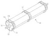
도 1은 본 발명의 일실시 예를 따른 접지 모듈의 구성을 도시한 사시도이다.1 is a perspective view showing the configuration of a ground module according to an embodiment of the present invention.
도 1을 참조하면, 퍼라이트 탄소 접지 모듈(10)은 저저항성 재료로 형성되며 그 내부에 전도성 금속재로 이루어진 심봉(11)이 박혀있는 제1 접지체(13)와 제1 접지체(13)의 외부에 일체로 형성되며, 흡습성이 뛰어난 퍼라이트 (perlite)를 포함하는 제2 접지체(15)를 포함한다.Referring to FIG. 1, the perlite
이에 더하여, 제2 접지체(15)의 외부에는 탄소 섬유 시트(17)가 추가로 마련되어 제1 접지체(13) 또는 제2 접지체(15)의 내부적 요인이나 외부적 요인에 의해 손상을 입게 될 경우 손상이 계속 진행되어 파괴되는 것을 방지한다. 탄소 섬유 시트(17)는 제2 접지체(15)의 양단부 및 대략 중앙부에 마련될 수 있다. 또 다르게 탄소 섬유 시트(17)는 제2 접지체(15)의 외부 전체면에 마련 될 수 있다. 이 탄성 섬유 시트(17)는 퍼라이트 탄소 접지 모듈(1) 외부의 크랙 등을 방지하기 위함이다.In addition, a
심봉(11)은 예컨대, 구리 또는 스테인레스 강으로 이루어진 고전도 체일 수 있다.The
제1 접지체(13)는 예컨대, 83wt%로 흑연이 주성분을 이루고, 성형을 위해 17wt%의 타르(tar)로 이루어져 전기 전도도가 약 99%에 이르도록 할 수 있다. 또 다르게, 제1 접지체(13)는 52wt%의 흑연 및 탄소 성분과 48wt%의 그 밖의 재료로 구성될 수 있다. 제1 접지체(13)는 각 성분을 혼합한 후 압축 성형 또는 소결 성형 될 수 있다.The
제1 접지체(13)는 저 저항성을 가지는 흑연을 주재료로 구성됨에 따라 낙뢰와 같은 서지 전압을 신속하게 대지로 전달할 수 있다.Since the
제1 접지체(13)에서 최소 순도 85~93%이상의 흑연을 83% 유지하는 것은 제조 후 전기저항성을 0Ω.m로 근접하게 유지하기 위함이며, 타르는 퍼라이트 탄소 모듈 성형을 유지하기 위한 최소량이다.Maintaining 83% of graphite with a minimum purity of 85 to 93% or more in the
상기와 같은 조건을 충족시키는 또 다른 형태의 접지체는 이건 발명의 발명자가 등록받은 “제0610604”호에 나타난 조성 성분에 의하여 제조된 접지체가 사용될 수 있음은 자명하다 할 것이다.As another type of grounding body which satisfies the above conditions, it will be apparent that the grounding body manufactured by the composition component shown in "0610604" registered by the inventor of the present invention can be used.
제2 접지체(15)는 제1 접지체(13)의 저항값보다 큰 저항값을 가지는 성분으로 성형된다. 그에 따라 낮은 저항을 유지하는 제1 접지체(13)와 대지와의 저항 차를 줄여주어 제1 접지체(13)를 통해 전달된 서지 전압이 신속하게 대지로 전달된다.The
이러한 제2 접지체(15)의 조성비는 다음과 같다.The composition ratio of the
다음 [표 1]에 나타낸 바와 같이 제2 접지체(15)는 47.62wt%의 퍼라이트, 33.33wt%의 흑연, 4.76wt%의 산화철, 4.76wt%의 산화 알루미늄, 9.53wt%의 도전성 시멘트로 혼합 반죽되어 대략 75kg/cm2±10% 로 가압 성형될 수 있다. 이와 같은 조성비를 따라 1,500g의 퍼라이트, 1,050g의 흑연, 150g의 산화철, 150g의 도전성 시멘트를 혼합하여 전체 무게가 3,150g인 제2 접지체(15)를 얻을 수 있었다.As shown in the following [Table 1], the
또 다르게, 제2 접지체(15)는 40.0wt%의 퍼라이트, 45.0wt%의 흑연, 4.0wt%의 산화철, 10.0wt%의 도전성 시멘트 및 1.0wt%의 은 나노 입자로 혼합 반죽되어 대략 75kg/cm2±10%로 가압 성형될 수 있다. 이와 같은 조성비를 따라 1,200g의 퍼라이트, 1,350g의 흑연, 120g의 산화철, 300g의 도전성 시멘트, 30g의 은나노 입자를 혼합하여 전체 무게가 3,000g인 제2 접지체(15)를 얻을 수 있었다.Alternatively, the
[표 1]TABLE 1
상술한 조성 비율은 본 출원인이 생산에 최적인 조건을 제시한 것에 불과하며, 생산 조건, 설계 조건 등에 따라 상기 퍼라이트 및 상기 흑연은 ±5% 범위, 상기 도전성 시멘트는 ±2% 범위, 상기 산화철 및 산화 알루미늄은 ±0.5% 범위, 상기 은 나노 입자는 ±0.3%범위 내에서 증감이 이루어질 수 있다.The above-described composition ratios are merely presenting the conditions for which the present applicant is optimal for production, and the perlite and the graphite in the range of ± 5%, the conductive cement in the range of ± 2%, the iron oxide and Aluminum oxide may be ± 0.5% range, the silver nanoparticles may be increased or decreased within ± 0.3% range.
제2 접지체(15)의 퍼라이트는 접지 시공 후 미세한 모공을 통한 모세관 현상에 의해 주변의 수분을 흡수, 유지함으로써 외부 환경변화에도 일정한 저항을 유지하게 해주기 위함이다.The perlite of the
또한, 제2 접지체(15)의 도전성 시멘트는 성형을 위하고, 흑연, 산화철, 산화알루미늄 및 은나노 입자는 전기 전도성을 개선하고 유지하기 위함이다.In addition, the conductive cement of the
퍼라이트는 다공성을 가짐에 따라 수분 흡수력과 습도 유지력을 향상시키는 이점을 제공함과 아울러서, 경량성 및 강도가 높은 성질들이 있어 제품을 무게를 경량화시키고 내구성을 좋게 하는 이점이 있다.Perlite has the advantage of improving the moisture absorption and humidity retention as it has a porosity, and also has the properties of light weight and high strength to lighten the product weight and durability.
퍼라이트는 2.5mm 이하의 표준 입도, 0.16kg/ℓ의 겉보기 비중, 4.0(ℓ/kg)의 최대 용수량, 0.045Kcal/mh℃의 열전도율을 가지며, 건조시 전기 저항률이 무한대이고, 수분 함침시 전기 저항률이 약 350KΩ·m 일 수 있다. Perlite has a standard particle size of 2.5mm or less, an apparent specific gravity of 0.16kg / ℓ, a maximum water content of 4.0 (ℓ / kg), a thermal conductivity of 0.045Kcal / mh ° C, an infinite electrical resistivity during drying, and an electrical resistivity during moisture impregnation. This may be about 350KΩ · m.
퍼라이트는 (주)미성 산업 등의 "파믹스 퍼라이트" 제품 또는 이와 동등한 제품을 사용할 수 있다.Perlite can use "Pamix perlite" products, such as Misung Industries Co., Ltd. or equivalent products.
이와 같은 특성을 가지는 퍼라이트를 이용하여 상기의 [표 1]과 같은 조성비로 제2 접지체(15)를 형성할 경우, 제2 접지체(15)의 전기 저항률은 1 내지 5Ω·m를 가질 수 있다. 이러한 전기 저항률은 성형 조건, 측정 조건 등에 따라 차이가 있을 수 있다.When the
은 나노는 입자 크기가 10nm 이하이고, 그 순도를 99.9%이상인 것이 적용될 수 있으며, (주)이앤비코리아 등에서 생산되는 은나노 입자를 사용할 수 있다.Silver nano particles having a particle size of 10 nm or less, the purity of 99.9% or more may be applied, and may be used silver nano particles produced by E & B Korea.
흑연은 입자 크기가 50㎛이고, 순도가 85%~93% 범위 내인 것으로 할 수 있 다.Graphite may have a particle size of 50 µm and a purity in the range of 85% to 93%.
산화철은 입자 크기를 0.65~1.0㎛의 범위 내로 적용할 수 있다.Iron oxide can be applied in the particle size in the range of 0.65 ~ 1.0㎛.
도전성 시멘트는 (주)고려전기상사의 "매직 어스" 제품 또는 이와 동등한 제품을 사용할 수 있다.As the conductive cement, "Magic Earth" products of Koryo Electric Co., Ltd. or equivalent products can be used.
제2 접지체(15)는 그 횡단면 형태가 원통형 또는 다각형으로 이루어지고, 그 표면에 길이 방향으로 복수의 골(15a)이 형성될 수 있다. 이와 같이 제2 접지체(15)는 복수의 골(15a)이 형성됨에 따라 그 표면적이 넓어지게 되어 지면에 매립되었을 때 수분 흡수력과 습도 유지력이 향상된다. 또 다르게, 제2 접지체 (15)의 내부에 제2 접지체(15)의 길이 방향을 따라 관통하는 홀(15c)을 길게 형성하여 수분 흡수력 및 습도 유지력이 향상되도록 할 수 있다.The
퍼라이트 탄소 접지모듈(10)의 크랙을 방지하기 위한 탄소 섬유 시트(17)는 그 섬유를 구성하는 탄소 원자의 결정 구조 때문에 높은 인장 강도와 인장 탄성 계수를 지니고 있으므로 제1 접지체(13) 또는 제2 접지체(15)를 유용하게 보강할 수 있다.The
탄소 섬유 시트(17)는 제2 접지체(15)의 외면 둘레에 대응하는 길이를 가지도록 띠형상으로 잘라서 예컨대, 상온 경화형 에폭시 수지와 같은 접착제를 통해 제2 접지체(15)에 접착된다.The
탄소 섬유 시트(17)는 전기 저항률이 0.002Ωm이고, 인장 강도가 2000㎫를 가질 수 있으며, 예컨대, 에스케이 케미칼(SK chemical)사의 SK-N200 제품 또는 이와 동등한 제품이 적용될 수 있다.The
상술한 바와 같은 퍼라이트 탄소 접지 모듈(10)은 제품 설계에 따라서 제 1접지체(13) 와 제2 접지체(15)의 중량비는 대략 4:1로 이루어질 수 있으며, ±10%의 범위 내에서 그 비율이 조정 될 수 있다.As described above, the perlite
일예로 퍼라이트 탄소 접지 모듈(10)은 5kg±10 wt%의 제1 접지체(13)와, 20kg±10 wt%의 제2 접지체(15)로 이루어질 수 있다.For example, the perlite
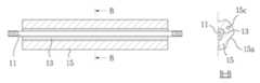
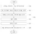
도 2a 내지 도 2c는 본 발명의 일실시 예를 따른 퍼라이트 탄소 모듈의 제조 과정을 설명하기 위한 도면이고, 도 3은 본 발명의 일실시 예를 따른 퍼라이트 탄소 접지 모듈의 제조 과정을 간략하게 나타낸 순서도이다.2a to 2c are views for explaining a manufacturing process of a perlite carbon module according to an embodiment of the present invention, Figure 3 is a flow chart briefly showing a manufacturing process of a perlite carbon grounding module according to an embodiment of the present invention to be.
도 2a 와 도 3과 같이, 먼저, 심재(11)를 포함하는 성형틀 내에 제1 접지체(13)를 이루는 원료 분말을 혼합 반죽한 재료를 충진하고, 압축 성형 또는/및 소결 성형을 통해 제1 접지체(13)를 형성한다(S10). 여기서, 제1 접지체(13)는 본 발명의 출원인이 이전에 출원한 등록특허번호 제06010604호의 "탄소 저저항 접지 모듈과 그 제조 방법"에 개시되어 있으며, 그 등록 특허의 내용은 본원 발명에 통합된다.2A and 3, first, a material obtained by mixing and kneading the raw material powder constituting the
다음 도 2b와 도 3과 같이, 제1 접지체(13)의 외부에 제2 접지체(15)를 압축 성형(pressing forming)(S20)하며, 그 구체적 제조 방법은 아래와 같다.Next, as shown in FIG. 2B and FIG. 3, the
먼저, 제2 접지체(15)를 이루는 원료 분말들을 혼합 반죽한 하고(S21), 성형틀 내에 혼합 반죽된 원료를 충진(S23)한다. 이때, 성형틀 내에는 심재(11)를 포함하는 제1 접지체(11)가 성형틀 내에 배치된 상태에서 혼합 반죽된 원료가 충진된다.First, mixing and kneading the raw material powders constituting the second grounding body 15 (S21), and filling the mixed kneaded raw material in the mold (S23). At this time, the raw material is mixed and kneaded in a state in which the
다음, 성형틀 내에 충진된 원료를 소정의 가압력 예컨대, 75kg/cm2±10%의 압력으로 가압(S25)한다. 이후, 성형틀을 제거(S27)하여 제2 접지체(15)를 제1 접지체(13)의 외부에 일체로 형성한다. 이때, 제2 접지체(15)의 외부 표면에는 그 길이 방향을 따라 복수의 골(15a)이 길게 형성되거나, 제2 접지체(15)의 내부에 그 길이 방향을 따라 관통되는 복수의 홀(15b)을 추가로 형성하여 수분 흡수력 및 습도 유지력 향상에 도움이 되도록 할 수 있다.Next, the raw material filled in the mold is pressurized (S25) at a predetermined pressing force, for example, a pressure of 75 kg / cm2 ± 10%. Thereafter, the mold is removed (S27) to form the
계속하여 도 2c와 도 3과 같이, 제2 접지체(15)의 외부 둘레와 대응되는 길이로 탄소 섬유 시트(17)를 자른 후 접착제를 이용하여 제2 접지체(15)의 외부에 접착(S30)하여 퍼라이트 탄소 접지 모듈(10)을 완성한다.Subsequently, as shown in FIGS. 2C and 3, the
상술한 내용에 있어서, 탄소 섬유 시트(17)가 제2 접지체(15)의 외부에 접착되는 방법을 예로 들어 설명하였으나, 이에 한정되지 않으며, 제2 접지체(15)를 성형하기 위한 성형틀 내부면에 탄소 섬유 시트(17)를 먼저 배치한 후, 제2 접지체(15)의 분말 원료를 충진한 후 가압 성형하는 것에 의해 퍼라이트 탄소 접지 모듈(10)을 완성할 수도 있다.In the above description, a method in which the
이상에서는 본 발명의 바람직한 실시 예를 설명하였으나, 본 발명의 범위는 이 같은 특정 실시 예에만 한정되지 않으며, 해당분야에서 통상의 지식을 가진 자라면 본 발명의 특허 청구 범위 내에 기재된 범주 내에서 적절하게 변경 또는 수정이 가능할 것이다.Although the preferred embodiments of the present invention have been described above, the scope of the present invention is not limited to such specific embodiments, and a person of ordinary skill in the art is properly within the scope described in the claims of the present invention. Changes or modifications may be made.
도 1은 본 발명의 일실시 예를 따른 퍼라이트 탄소 접지 모듈의 구성을 도시한 사시도이다.1 is a perspective view showing the configuration of a perlite carbon grounding module according to an embodiment of the present invention.
도 2a 내지 도 2c는 본 발명의 일실시 예를 따른 퍼라이트 탄소 접지 모듈의 제조 과정을 설명하기 위한 설명도이다. 그리고,2A to 2C are explanatory views for explaining a manufacturing process of a perlite carbon grounding module according to an embodiment of the present invention. And,
도 3은 본 발명의 일실시 예를 따른 퍼라이트 탄소 접지 모듈의 제조 과정을 설명하는 순서도이다.Figure 3 is a flow chart illustrating a manufacturing process of a perlite carbon ground module according to an embodiment of the present invention.
Claims (9)
Translated fromKoreanPriority Applications (1)
| Application Number | Priority Date | Filing Date | Title |
|---|---|---|---|
| KR1020080073129AKR100875504B1 (en) | 2008-07-25 | 2008-07-25 | Perlite Carbon Ground Module |
Applications Claiming Priority (1)
| Application Number | Priority Date | Filing Date | Title |
|---|---|---|---|
| KR1020080073129AKR100875504B1 (en) | 2008-07-25 | 2008-07-25 | Perlite Carbon Ground Module |
Publications (1)
| Publication Number | Publication Date |
|---|---|
| KR100875504B1true KR100875504B1 (en) | 2008-12-26 |
Family
ID=40373055
Family Applications (1)
| Application Number | Title | Priority Date | Filing Date |
|---|---|---|---|
| KR1020080073129AExpired - Fee RelatedKR100875504B1 (en) | 2008-07-25 | 2008-07-25 | Perlite Carbon Ground Module |
Country Status (1)
| Country | Link |
|---|---|
| KR (1) | KR100875504B1 (en) |
Cited By (9)
| Publication number | Priority date | Publication date | Assignee | Title |
|---|---|---|---|---|
| CN102237579A (en)* | 2010-04-30 | 2011-11-09 | 国网电力科学研究院武汉南瑞有限责任公司 | Magnetic ferric oxide electrode |
| CN102237578A (en)* | 2010-04-21 | 2011-11-09 | 三门峡电力设计有限责任公司 | Electric single-pole point type grounding device for urban area |
| KR101114999B1 (en) | 2010-10-11 | 2012-03-06 | (주)옴니엘피에스 | A device for assessing the length of carbon ground electrode module based on a two-level distributed parameter circuit model and the method thereof |
| WO2012027594A3 (en)* | 2010-08-27 | 2012-06-07 | Intel Corporation | Techniques for augmenting a digital on-screen graphic |
| KR101523645B1 (en)* | 2015-01-23 | 2015-05-29 | 정용기 | Grounding module made by combination of graphite, perlite and vermiculite |
| KR101524437B1 (en)* | 2015-01-23 | 2015-05-29 | 정용기 | Grounding module made by combination of graphite, perlite and vermiculite |
| CN105929274A (en)* | 2016-05-03 | 2016-09-07 | 国网江西省电力科学研究院 | Apparatus and method for impact current test of dimension adjustable grounding module |
| KR101733158B1 (en) | 2016-02-04 | 2017-05-08 | (주)옴니엘피에스 | Carbon resistors apparatus for grounding module |
| EP2528068A3 (en)* | 2011-05-19 | 2018-04-04 | Omni LPS. Co., Ltd. | Low-resistance carbon grounding module and method for manufacturing the same |
Citations (2)
| Publication number | Priority date | Publication date | Assignee | Title |
|---|---|---|---|---|
| JPH11260516A (en) | 1998-03-11 | 1999-09-24 | Toagosei Co Ltd | Grounding resistance reducing aggregate and grounding resistance reducing material |
| KR100805958B1 (en)* | 2007-06-12 | 2008-02-21 | (주)의제전기설비연구원 | Metal nano-coated ground electrode and its manufacturing method |
- 2008
- 2008-07-25KRKR1020080073129Apatent/KR100875504B1/ennot_activeExpired - Fee Related
Patent Citations (2)
| Publication number | Priority date | Publication date | Assignee | Title |
|---|---|---|---|---|
| JPH11260516A (en) | 1998-03-11 | 1999-09-24 | Toagosei Co Ltd | Grounding resistance reducing aggregate and grounding resistance reducing material |
| KR100805958B1 (en)* | 2007-06-12 | 2008-02-21 | (주)의제전기설비연구원 | Metal nano-coated ground electrode and its manufacturing method |
Cited By (16)
| Publication number | Priority date | Publication date | Assignee | Title |
|---|---|---|---|---|
| CN102237578A (en)* | 2010-04-21 | 2011-11-09 | 三门峡电力设计有限责任公司 | Electric single-pole point type grounding device for urban area |
| CN102237579A (en)* | 2010-04-30 | 2011-11-09 | 国网电力科学研究院武汉南瑞有限责任公司 | Magnetic ferric oxide electrode |
| CN102237579B (en)* | 2010-04-30 | 2013-03-06 | 国网电力科学研究院武汉南瑞有限责任公司 | Magnetic ferric oxide electrode |
| WO2012027594A3 (en)* | 2010-08-27 | 2012-06-07 | Intel Corporation | Techniques for augmenting a digital on-screen graphic |
| KR101114999B1 (en) | 2010-10-11 | 2012-03-06 | (주)옴니엘피에스 | A device for assessing the length of carbon ground electrode module based on a two-level distributed parameter circuit model and the method thereof |
| US20130197840A1 (en)* | 2010-10-11 | 2013-08-01 | Omni Lps. Co., Ltd. | Apparatus and method for calculating length of carbon grounding electrode module based on two-layered distributed constant circuit |
| EP2629372A4 (en)* | 2010-10-11 | 2014-11-12 | Omni Lps Co Ltd | Apparatus and method for calculating length of carbon grounding electrode module based on two-layered distributed constant circuit |
| EP2528068A3 (en)* | 2011-05-19 | 2018-04-04 | Omni LPS. Co., Ltd. | Low-resistance carbon grounding module and method for manufacturing the same |
| KR101524437B1 (en)* | 2015-01-23 | 2015-05-29 | 정용기 | Grounding module made by combination of graphite, perlite and vermiculite |
| WO2016117771A1 (en)* | 2015-01-23 | 2016-07-28 | 정용기 | Composite grounding module formed from graphite, pearlstone and vermiculite |
| WO2016117770A1 (en)* | 2015-01-23 | 2016-07-28 | 정용기 | Composite grounding module formed from graphite, pearlstone and vermiculite |
| CN107210546A (en)* | 2015-01-23 | 2017-09-26 | 郑龙基 | By the earthing module of the combination manufacture of graphite, perlite and vermiculite |
| CN107210547A (en)* | 2015-01-23 | 2017-09-26 | 郑龙基 | By the earthing module of the combination manufacture of graphite, perlite and vermiculite |
| KR101523645B1 (en)* | 2015-01-23 | 2015-05-29 | 정용기 | Grounding module made by combination of graphite, perlite and vermiculite |
| KR101733158B1 (en) | 2016-02-04 | 2017-05-08 | (주)옴니엘피에스 | Carbon resistors apparatus for grounding module |
| CN105929274A (en)* | 2016-05-03 | 2016-09-07 | 国网江西省电力科学研究院 | Apparatus and method for impact current test of dimension adjustable grounding module |
Similar Documents
| Publication | Publication Date | Title |
|---|---|---|
| KR100875504B1 (en) | Perlite Carbon Ground Module | |
| KR101477430B1 (en) | Multi-layered ceramic electronic part, manufacturing method thereof and board having the same mounted thereon | |
| CN1681052B (en) | Nonlinear electrical material for high and medium voltage applications | |
| KR102041629B1 (en) | Multilayer ceramic electronic component and method for manufacturing the same | |
| EP2124233B1 (en) | Zno varistor powder | |
| US9520234B2 (en) | Multilayer ceramic capacitor, manufacturing method thereof and board for mounting the same thereon | |
| CN106133849A (en) | Soft magnetism molded body, magnetic core and magnetic piece | |
| EP1624537A3 (en) | Screened surge arrester | |
| CN102142430B (en) | Chip type high polymer electrostatic discharge protecting element and manufacturing method thereof | |
| JP2004297020A (en) | Ceramic electronic component and its manufacturing method | |
| CN111986876B (en) | Laminated coil component | |
| WO2017022373A1 (en) | Temperature sensor | |
| JPWO2007148438A1 (en) | Magnetic antenna and ferrite sintered body | |
| CN104086170B (en) | The preparation method of low voltage varistor ceramic plate and preparation method thereof, low-voltage piezoresistor | |
| Bora et al. | Polyvinylbutyral–polyaniline nanocomposite for high microwave absorption efficiency | |
| KR102079178B1 (en) | Multilayer ceramic electronic parts | |
| KR101681386B1 (en) | Lead-free piezoelectric ceramic composition and Preparation method thereof | |
| KR101523645B1 (en) | Grounding module made by combination of graphite, perlite and vermiculite | |
| JP6089220B2 (en) | Voltage nonlinear resistor composition and multilayer varistor using the same | |
| JP2004022976A (en) | Stacked voltage nonlinear resistor and method of manufacturing the same | |
| CN101891461B (en) | Li2O-CoO-TiO2 ternary system microwave dielectric material and low-temperature sintering method | |
| KR101978426B1 (en) | Circuit protection device and mobile electronic device with the same | |
| JPH10229003A (en) | Varistor, chip-type varistor, and manufacture of varistor | |
| CN210091842U (en) | Novel SMD overcurrent protection component | |
| CN201229818Y (en) | Belt pin type high molecular PTC over-current over-warming protection element |
Legal Events
| Date | Code | Title | Description |
|---|---|---|---|
| A201 | Request for examination | ||
| PA0109 | Patent application | St.27 status event code:A-0-1-A10-A12-nap-PA0109 | |
| PA0201 | Request for examination | St.27 status event code:A-1-2-D10-D11-exm-PA0201 | |
| A302 | Request for accelerated examination | ||
| PA0302 | Request for accelerated examination | St.27 status event code:A-1-2-D10-D17-exm-PA0302 St.27 status event code:A-1-2-D10-D16-exm-PA0302 | |
| D13-X000 | Search requested | St.27 status event code:A-1-2-D10-D13-srh-X000 | |
| D14-X000 | Search report completed | St.27 status event code:A-1-2-D10-D14-srh-X000 | |
| E902 | Notification of reason for refusal | ||
| PE0902 | Notice of grounds for rejection | St.27 status event code:A-1-2-D10-D21-exm-PE0902 | |
| E13-X000 | Pre-grant limitation requested | St.27 status event code:A-2-3-E10-E13-lim-X000 | |
| P11-X000 | Amendment of application requested | St.27 status event code:A-2-2-P10-P11-nap-X000 | |
| P13-X000 | Application amended | St.27 status event code:A-2-2-P10-P13-nap-X000 | |
| E701 | Decision to grant or registration of patent right | ||
| PE0701 | Decision of registration | St.27 status event code:A-1-2-D10-D22-exm-PE0701 | |
| GRNT | Written decision to grant | ||
| PR0701 | Registration of establishment | St.27 status event code:A-2-4-F10-F11-exm-PR0701 | |
| PR1002 | Payment of registration fee | St.27 status event code:A-2-2-U10-U11-oth-PR1002 Fee payment year number:1 | |
| PG1601 | Publication of registration | St.27 status event code:A-4-4-Q10-Q13-nap-PG1601 | |
| PN2301 | Change of applicant | St.27 status event code:A-5-5-R10-R13-asn-PN2301 St.27 status event code:A-5-5-R10-R11-asn-PN2301 | |
| PR1001 | Payment of annual fee | St.27 status event code:A-4-4-U10-U11-oth-PR1001 Fee payment year number:4 | |
| R18-X000 | Changes to party contact information recorded | St.27 status event code:A-5-5-R10-R18-oth-X000 | |
| FPAY | Annual fee payment | Payment date:20121205 Year of fee payment:5 | |
| PR1001 | Payment of annual fee | St.27 status event code:A-4-4-U10-U11-oth-PR1001 Fee payment year number:5 | |
| PN2301 | Change of applicant | St.27 status event code:A-5-5-R10-R11-asn-PN2301 | |
| PN2301 | Change of applicant | St.27 status event code:A-5-5-R10-R14-asn-PN2301 | |
| S14-X000 | Exclusive voluntary license recorded | St.27 status event code:A-4-4-S10-S14-lic-X000 | |
| FPAY | Annual fee payment | Payment date:20131209 Year of fee payment:6 | |
| PR1001 | Payment of annual fee | St.27 status event code:A-4-4-U10-U11-oth-PR1001 Fee payment year number:6 | |
| FPAY | Annual fee payment | Payment date:20141212 Year of fee payment:7 | |
| PR1001 | Payment of annual fee | St.27 status event code:A-4-4-U10-U11-oth-PR1001 Fee payment year number:7 | |
| FPAY | Annual fee payment | Payment date:20151211 Year of fee payment:8 | |
| PR1001 | Payment of annual fee | St.27 status event code:A-4-4-U10-U11-oth-PR1001 Fee payment year number:8 | |
| R18-X000 | Changes to party contact information recorded | St.27 status event code:A-5-5-R10-R18-oth-X000 | |
| S14-X000 | Exclusive voluntary license recorded | St.27 status event code:A-4-4-S10-S14-lic-X000 | |
| FPAY | Annual fee payment | Payment date:20170602 Year of fee payment:9 | |
| PR1001 | Payment of annual fee | St.27 status event code:A-4-4-U10-U11-oth-PR1001 Fee payment year number:9 | |
| PC1903 | Unpaid annual fee | St.27 status event code:A-4-4-U10-U13-oth-PC1903 Not in force date:20171217 Payment event data comment text:Termination Category : DEFAULT_OF_REGISTRATION_FEE | |
| FPAY | Annual fee payment | Payment date:20180917 Year of fee payment:10 | |
| K11-X000 | Ip right revival requested | St.27 status event code:A-6-4-K10-K11-oth-X000 | |
| PC1903 | Unpaid annual fee | St.27 status event code:N-4-6-H10-H13-oth-PC1903 Ip right cessation event data comment text:Termination Category : DEFAULT_OF_REGISTRATION_FEE Not in force date:20171217 | |
| PR0401 | Registration of restoration | St.27 status event code:A-6-4-K10-K13-oth-PR0401 | |
| PR1001 | Payment of annual fee | St.27 status event code:A-4-4-U10-U11-oth-PR1001 Fee payment year number:10 | |
| R401 | Registration of restoration | ||
| FPAY | Annual fee payment | Payment date:20181218 Year of fee payment:11 | |
| PR1001 | Payment of annual fee | St.27 status event code:A-4-4-U10-U11-oth-PR1001 Fee payment year number:11 | |
| PR1001 | Payment of annual fee | St.27 status event code:A-4-4-U10-U11-oth-PR1001 Fee payment year number:12 | |
| PR1001 | Payment of annual fee | St.27 status event code:A-4-4-U10-U11-oth-PR1001 Fee payment year number:13 | |
| PN2301 | Change of applicant | St.27 status event code:A-5-5-R10-R11-asn-PN2301 | |
| PN2301 | Change of applicant | St.27 status event code:A-5-5-R10-R14-asn-PN2301 | |
| R18-X000 | Changes to party contact information recorded | St.27 status event code:A-5-5-R10-R18-oth-X000 | |
| P14-X000 | Amendment of ip right document requested | St.27 status event code:A-5-5-P10-P14-nap-X000 | |
| P16-X000 | Ip right document amended | St.27 status event code:A-5-5-P10-P16-nap-X000 | |
| Q16-X000 | A copy of ip right certificate issued | St.27 status event code:A-4-4-Q10-Q16-nap-X000 | |
| PR1001 | Payment of annual fee | St.27 status event code:A-4-4-U10-U11-oth-PR1001 Fee payment year number:14 | |
| S14-X000 | Exclusive voluntary license recorded | St.27 status event code:A-4-4-S10-S14-lic-X000 | |
| PR1001 | Payment of annual fee | St.27 status event code:A-4-4-U10-U11-oth-PR1001 Fee payment year number:15 | |
| PR1001 | Payment of annual fee | St.27 status event code:A-4-4-U10-U11-oth-PR1001 Fee payment year number:16 | |
| PR1001 | Payment of annual fee | St.27 status event code:A-4-4-U10-U11-oth-PR1001 Fee payment year number:17 |