KR100874519B1 - Mobile robot and clinical test device using the same - Google Patents
Mobile robot and clinical test device using the sameDownload PDFInfo
- Publication number
- KR100874519B1 KR100874519B1KR1020070069992AKR20070069992AKR100874519B1KR 100874519 B1KR100874519 B1KR 100874519B1KR 1020070069992 AKR1020070069992 AKR 1020070069992AKR 20070069992 AKR20070069992 AKR 20070069992AKR 100874519 B1KR100874519 B1KR 100874519B1
- Authority
- KR
- South Korea
- Prior art keywords
- mobile robot
- mobile
- gripper
- stage unit
- plate
- Prior art date
- Legal status (The legal status is an assumption and is not a legal conclusion. Google has not performed a legal analysis and makes no representation as to the accuracy of the status listed.)
- Expired - Fee Related
Links
Images


Classifications
- G—PHYSICS
- G01—MEASURING; TESTING
- G01N—INVESTIGATING OR ANALYSING MATERIALS BY DETERMINING THEIR CHEMICAL OR PHYSICAL PROPERTIES
- G01N35/00—Automatic analysis not limited to methods or materials provided for in any single one of groups G01N1/00 - G01N33/00; Handling materials therefor
- G01N35/10—Devices for transferring samples or any liquids to, in, or from, the analysis apparatus, e.g. suction devices, injection devices
- A—HUMAN NECESSITIES
- A61—MEDICAL OR VETERINARY SCIENCE; HYGIENE
- A61B—DIAGNOSIS; SURGERY; IDENTIFICATION
- A61B5/00—Measuring for diagnostic purposes; Identification of persons
- G—PHYSICS
- G01—MEASURING; TESTING
- G01N—INVESTIGATING OR ANALYSING MATERIALS BY DETERMINING THEIR CHEMICAL OR PHYSICAL PROPERTIES
- G01N35/00—Automatic analysis not limited to methods or materials provided for in any single one of groups G01N1/00 - G01N33/00; Handling materials therefor
- G—PHYSICS
- G01—MEASURING; TESTING
- G01N—INVESTIGATING OR ANALYSING MATERIALS BY DETERMINING THEIR CHEMICAL OR PHYSICAL PROPERTIES
- G01N35/00—Automatic analysis not limited to methods or materials provided for in any single one of groups G01N1/00 - G01N33/00; Handling materials therefor
- G01N35/0099—Automatic analysis not limited to methods or materials provided for in any single one of groups G01N1/00 - G01N33/00; Handling materials therefor comprising robots or similar manipulators
- G—PHYSICS
- G01—MEASURING; TESTING
- G01N—INVESTIGATING OR ANALYSING MATERIALS BY DETERMINING THEIR CHEMICAL OR PHYSICAL PROPERTIES
- G01N35/00—Automatic analysis not limited to methods or materials provided for in any single one of groups G01N1/00 - G01N33/00; Handling materials therefor
- G01N35/02—Automatic analysis not limited to methods or materials provided for in any single one of groups G01N1/00 - G01N33/00; Handling materials therefor using a plurality of sample containers moved by a conveyor system past one or more treatment or analysis stations
- G01N35/04—Details of the conveyor system
Landscapes
- Health & Medical Sciences (AREA)
- Life Sciences & Earth Sciences (AREA)
- General Health & Medical Sciences (AREA)
- Pathology (AREA)
- Physics & Mathematics (AREA)
- Immunology (AREA)
- Analytical Chemistry (AREA)
- Biochemistry (AREA)
- Chemical & Material Sciences (AREA)
- General Physics & Mathematics (AREA)
- Engineering & Computer Science (AREA)
- Heart & Thoracic Surgery (AREA)
- Biophysics (AREA)
- Biomedical Technology (AREA)
- Medical Informatics (AREA)
- Molecular Biology (AREA)
- Surgery (AREA)
- Animal Behavior & Ethology (AREA)
- Public Health (AREA)
- Veterinary Medicine (AREA)
- Robotics (AREA)
- Automatic Analysis And Handling Materials Therefor (AREA)
- Manipulator (AREA)
Abstract
Translated fromKoreanDescription
Translated fromKorean본 발명은 임상 시험을 수행하기 위한 장치에 관한 것으로, 보다 상세하게는 모바일 로봇을 이용한 임상 시험 장치에 관한 것이다.The present invention relates to a device for performing a clinical trial, and more particularly to a clinical trial device using a mobile robot.
인류가 지구상에 나타난 이래로 인간은 병에 걸리지 않고 오래 살기 위한 생명연장의 꿈을 이루기 위해 각종 수단과 방법을 동원하고 있다. 최근에는 각종 질병을 정복하고 생명을 비약적으로 연장할 수 있는 새로운 기술들이 개발되고 있으며, 인간의 삶이 부유해짐에 따라 자신과 가족의 건강에 대한 관심은 더욱 높아지고 있다.Since mankind appeared on earth, human beings have mobilized various means and methods to achieve their dream of prolonging life without disease. Recently, new technologies are being developed to overcome various diseases and prolong life dramatically, and as human life becomes rich, interest in self and family health is increasing.
병을 고치기 위해 병원을 찾아가던 시대에서, 이제는 병을 예방하기 위해 병원을 찾아가고 자신의 모든 건강상태를 검사하고 관리해 주는 시대로 바뀌고 있다. 개인의 건강 상태(health status)를 확인하기 위해 다양한 종류의 임상 시험이 수행되고 있다.From the days of visiting hospitals to cure sicknesses, it is now time to visit hospitals to prevent illnesses and to examine and manage all of your health conditions. Various types of clinical trials are being conducted to ascertain the health status of an individual.
임상 시험(clinical test)는 혈액 시험(hematological test), 면역 시험( immunoassay), 중독학(toxicology), 소변 검사(urinalysis) 및 혈액(blood), 혈 정(serum), 소변(urine) 등과 같은 생물학적 물질(biological material)의 시료(sample)를 시험하는 다른 특정 카테고리의 시험을 포함한다. 임상 시험은 각 개인의 건강 상태와 관련된 매우 귀중한(invaluable) 정보를 제공한다. 임상 시험의 결과는 일반적으로 진단 평가(diagnostic evaluation), 수술 결정(surgical decision making), 환자의 건강 상태에서 발생하는 변화의 인식을 위해 사용된다.Clinical tests include hematological tests, immunoassays, toxicology, urinalysis and biological tests such as blood, serum, urine, etc. It includes other specific categories of tests that test samples of biological materials. Clinical trials provide very valuable information related to the health status of each individual. The results of clinical trials are generally used for diagnostic evaluation, surgical decision making, and recognition of changes that occur in the patient's health.
임상 시험은 높은 정밀도를 갖는 정보를 생성하기 위해 비전의(esoteric) 비싼(costly) 과정을 포함한다. 임상 시험에 드는 비용을 절감하기 위해 자동화 장치가 등장하고 있다.Clinical trials include esoteric and expensive processes to generate information with high precision. Automated devices are emerging to reduce the cost of clinical trials.
"Conveyor System for clinical test apparatus"라는 제목의 미국특허 제6,374,989호는 임시 콘베이어 레인(auxiliary conveyor lane)을 구비한 임상 시험용 콘베이어 시스템을 개시한다. "Automated Sampling and Testing of Biological Materials"라는 제목의 미국특허 제5,623,415호는 전송 레인(transport lane)과 대기 레인(queue lane)을 두고, 시료를 대기 레인에서 전송 레인으로 이송하는 자동화 장치를 개시한다.U.S. Patent No. 6,374,989 entitled "Conveyor System for Clinical Test Apparatus" discloses a clinical trial conveyor system with an auxiliary conveyor lane. U.S. Patent No. 5,623,415 entitled "Automated Sampling and Testing of Biological Materials" discloses an automated apparatus for transporting a sample from a standby lane to a transmission lane with a transport lane and a queue lane.
콘베이어나 기타 다른 시료(sample)나 시약(reagnet)를 이송하기 위한 수단은 일반적으로 부피가 크고, 특정 임상 시험 장치에 특화되어 있다. 이들은 일단 시스템에 장착되면 바꾸기 어려운 영속성(permanance)와 비유연성(inflexbilibty)의 특징을 가진다. 예를 들어, 콘베이어에 이상이 발생하면 전체 시스템이 멈추어야 한다.Means for conveying conveyors or other samples or reagents are generally bulky and specialized for specific clinical trial devices. They are characterized by permanance and inflexbilibty that are difficult to change once mounted in the system. For example, if something goes wrong with the conveyor, the whole system should stop.
임상 시험에 드는 비용을 절감하기 위해서는 가능한 신속하게 수행할 필요가 있다. 종래의 컨베이어 시스템에 의하면, 하나의 콘베이어는 한번에 하나의 시료 또는 시약을 이송할 수 밖에 없으므로 한번에 하나의 임상 시험을 실시하는 직렬적인(serial) 구조가 될 수 밖에 없다.To reduce the cost of clinical trials, they need to be carried out as soon as possible. According to the conventional conveyor system, one conveyor can only transfer one sample or reagent at a time, and thus, a conveyor can be used as a serial structure for conducting one clinical test at a time.
앞으로의 임상 시험 경향에 따른 주문형 임상 시험을 실현하기 위해서는 유연성과 소형성을 갖춘 임상 시험 장치가 필요하다.In order to realize custom clinical trials according to future clinical trial trends, a clinical trial apparatus with flexibility and compactness is required.
본 발명이 이루고자 하는 기술적 과제는 다수의 임상 시험을 병렬적으로 수행할 수 있는 임상 시험 장치를 제공하는 데에 있다.The technical problem to be achieved by the present invention is to provide a clinical trial apparatus that can perform a number of clinical trials in parallel.
본 발명이 이루고자 하는 다른 기술적 과제는 임상 시험 장치에 유연성을 제공하는 모바일 로봇을 제공하는 데에 있다.Another technical problem to be achieved by the present invention is to provide a mobile robot that provides flexibility to a clinical trial device.
임상 시험을 위한 과정은 시험을 위한 스케줄링, 시약 및 시료의 적재, 시료 인식, 시료 및 시약의 분배, 이송, 인큐베이션 및 측정으로 구성된다. 임상 시험의 유연성과 다양성을 확보하기 위해, 시약 및 시료의 이송을 모바일 로봇이 담당한다.Procedures for clinical trials consist of scheduling for testing, loading of reagents and samples, sample recognition, dispensing, transport, incubation and measurement of samples and reagents. Mobile robots are responsible for the transfer of reagents and samples to ensure flexibility and diversity of clinical trials.
임상 시험 장치는 스테이지 유닛, 상기 스테이지 유닛에 마련되어 임상 시험을 수행하는 시험 스테이션, 상기 스테이지 유닛의 상부면을 이동하며, 시료 및 시약이 적재된 플레이트를 상기 시험 스테이션으로 이송하는 모바일 로봇 및 상기 스테이지 유닛에 배치되어 상기 모바일 로봇의 위치를 초기화하는 도킹 유닛을 포함한다.The clinical test apparatus includes a stage unit, a test station provided in the stage unit to perform a clinical test, a mobile robot and a stage unit moving a top surface of the stage unit and transferring a plate loaded with a sample and a reagent to the test station. It is disposed in the docking unit for initializing the position of the mobile robot.
모바일 로봇은 시료 및 시약이 적재되는 플레이트가 안착되는 진단 모듈 및The mobile robot includes a diagnostic module on which a plate on which samples and reagents are loaded is placed.
상기 진단 모듈이 장착되고, 상기 진단 모듈을 임상 시험을 수행하는 시험 스테이션으로 이송하기 위한 모바일 모듈을 포함한다.The diagnostic module is mounted and includes a mobile module for transferring the diagnostic module to a test station for conducting a clinical trial.
임상 시험을 위한 다양한 시험 스테이션이 통합되고, 다수의 모바일 로봇을 통해 동시에 시험을 수행할 수 있어, 임상 시험에 소요되는 시간을 줄일 수 있다. 또한, 소형의 모바일 로봇을 통해 임상 시험 장치에 설치의 유연성을 제공하고, 전체 장치의 부피를 줄일 수 있다.Various test stations for clinical trials are integrated and tests can be performed simultaneously via multiple mobile robots, reducing the time required for clinical trials. In addition, the small mobile robots provide installation flexibility in clinical trial devices and reduce the volume of the entire device.
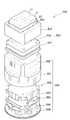
도 1은 임상 시험 장치를 나타낸 사시도이다.1 is a perspective view of a clinical trial apparatus.
도 1을 참조하면, 임상 시험 장치(100)는 스테이지 유닛(stage unit, 200), 시험 스테이션(test station, 300), 도킹 유닛(docking unit, 400), 모바일 로봇(500) 및 이송 유닛(transfer unit, 600)을 포함한다.Referring to FIG. 1, the
스테이지 유닛(200)은 전체 프레임을 형성하고, 그 상부에 시험 스테이션(300), 도킹 유닛(400) 및 이송 유닛(600)이 장착된다. 시험 스테이션(300) 하부의 스테이지 유닛(200) 내부에는 인큐베이터(미도시)가 마련된다. 모바일 로봇(500)은 스테이지 유닛(200)의 상부면을 돌아다니며, 모바일 로봇(500)에 장착된 플레이트(P)를 시험 스테이션(300), 도킹 유닛(400) 및 이송 유닛(600)으로 옮긴다. 스테이지 유닛(200)의 상부면에는 다수의 랜드마크(210)가 마련되어, 모바일 로봇(500)의 이동에 따른 위치 오차를 보정한다.The
시험 스테이션(300)은 실제 임상 시험을 수행하는 장치로, 이송된 플레이트(P)에 적재된 시약과 시료의 반응을 통해 임상 시험 결과를 추출한다. 후술하는 바와 같이 시험 스테이션(300)은 광원(미도시)을 구비하고, 광원은 빛을 시약과 시료가 적재된 플레이트(P)로 쏘고, 모바일 로봇(500)의 진단 모듈에 포함된 검출기 (도 2의 525)로부터 상기 빛의 투광도 등을 측정함으로써 임상 시험 결과를 산출한다.The
도킹 유닛(400)은 모바일 로봇(500)이 초기화 위치를 잡는 곳이다. 즉, 모바일 로봇(500)은 도킹 유닛(400)에 도킹되어 위치 정보를 초기화한다. 또한, 모바일 로봇(500)이 도킹 유닛(400)에 도킹되면, 모바일 로봇(500)에 내장된 배터리(미도시)를 충전한다.
이송 유닛(600)은 플레이트(P)를 모바일 로봇(500)으로 로딩/언로딩한다. 또한, 시료 및/또는 시약을 플레이트(P)에 투여한다.The
도 2는 모바일 로봇을 나타낸 분해 사시도이다.2 is an exploded perspective view showing a mobile robot.
도 2를 참조하면, 모바일 로봇(500)은 진단 모듈(520)과 모바일 모듈(550)을 포함한다. 모바일 모듈(550)은 진단 모듈(520)을 상단에 장착하고, 스테이지 유닛(200)의 상부면을 이동한다. 진단 모듈(520)은 플레이트(P)가 장착되어, 플레이트(P)로부터 임상 시험 정보를 인식하고, 시험 스테이션(300)과 연동하여 임상 시험 결과를 산출한다.Referring to FIG. 2, the
플레이트(P)는 다수의 홈(11)를 일정 간격으로 배열하여 각 홈(11)에 시료를 적재하고, 시약을 투여함으로써 임상 시험을 수행할 수 있도록 하는 의료용 플레이트이다. 플레이트(P)는 투명 재질로 이루어질 수 있다. 플레이트(P)에는 적재된 시료나 시약 등의 임상 시험 정보를 포함하는 RFID 태그(13)가 부착된다. RFID 태그(13)는 예시에 불과하고, 플레이트(P)에 바코드를 부착하여 임상 시험 정보를 포함시킬 수 있다.The plate P is a medical plate that arranges a plurality of
진단 모듈(520)은 진단 커버(521), RFID(Radio Frequency IDdentification) 리더(522), 검출기(525) 및 인터페이스 보드(527)를 포함한다.The
진단 커버(521)는 진단 모듈(520)의 외형을 형성하고, 상단에 플레이트(P)가 안착된다.The
RFID 리더(522)는 진단 커버(521)에 배치되어, 진단 커버(521)에 안착되는 플레이트(P)에 부착된 RFID 태그(13)를 읽는다. RFID 태그(13)는 환자 정보와 같은 임상 시험 정보를 포함한다. RFID 태그(13)로부터 읽혀지는 임상 시험 정보는 인터페이스 보드(527)를 통해 모바일 모듈(550)의 전기 기판(554)의 DSP(미도시)로 전달되고, 이는 다시 시험 스테이션(300)으로 전달된다.The RFID reader 522 is disposed on the
검출기(525)는 진단 커버(521)에 고정되어, 플레이트(P)의 배면과 대향하여 배치된다. 검출기(525)는 플레이트(P)가 시험 스테이션(300)으로 진입하여 임상 시험을 수행할 때, 임상 시험 결과를 측정한다. 검출기(525)는 분광 광도계(spectrophotometer)일 수 있다. 즉, 시험 스테이션(300)의 광원이 플레이트(P) 상부에서 빛을 방출하면, 시료와 시약이 반응한 곳을 지나는 빛의 투광도가 바뀌게 된다. 투광도가 바뀐 광을 플레이트(P)의 배면에 위치한 검출기(525)가 읽어 시험 스테이션(300)으로 전달함으로써 임상 시험 결과를 알 수 있다.The
인터페이스 보드(527)는 마이크로 프로세서를 포함하고, 모바일 모듈(550)의 전기 기판(554)과 연결되어, 전기 기판(554)에 배치된 DSP(Digital Signal Processor)와 통신한다.The
모바일 모듈(550)은 외형을 형성하는 외부 몸체(551) 및 상기 외부 몸 체(552) 내부에 마련되는 내부 몸체(552)를 포함한다. 내부 몸체(552)는 충전 커넥터(553), 전기 기판(554) 및 바퀴(556) 및 베이스(559)를 포함한다. 충전 커넥터(553)는 후술할 도킹 유닛(400)의 충전 단자와 연결되어 내부 몸체(552)에 장착된 배터리(미도시)를 충전한다. 배터리는 리튬-이온 배터리를 사용할 수 있다. 충전 커넥터(553)에 대응하는 외부 몸체(551)에는 홈(558)이 형성되어 충전 커넥터(553)를 외부로 노출시킨다. 전기 기판(554)은 모바일 로봇(500)의 제어기 역할을 하는 DSP(미도시)와 블루투스(Bluetooth) 모듈(미도시)이 장착된다. 내부 몸체(556)의 하부에는 베이스(559)가 마련되고, 베이스(559)에는 한 쌍의 바퀴(556)가 배치되어 모바일 로봇(500)의 구동력을 제공한다. 바퀴(556)에는 모터(미도시)가 연결되어 동력을 제공하고, 인코더(미도시)가 연결되어 모바일 로봇(500)의 위치를 측정한다.The
모바일 모듈(550)의 둘레에는 초음파 센서(미도시)가 장착되어, 다수의 모바일 로봇(500)을 운용함에 따라 발생할 수 있는 모바일 로봇(500)의 충돌을 감지하도록 할 수 있다.An ultrasonic sensor (not shown) may be mounted around the
도 3은 모바일 로봇의 밑면을 나타낸 사시도이다.3 is a perspective view showing the bottom of the mobile robot.
도 3을 참조하면, 모바일 모듈(550)의 베이스(559)에는 2개의 바퀴(556)이 외부로 돌출된다. 바퀴(556)는 스테이지 유닛(200)의 상부면에 접촉하여, 마찰력에 의해 모바일 로봇(500)이 스테이지 유닛(200)의 상부면을 이동할 수 있도록 한다. 또한, 2개의 바퀴(556)가 이루는 직선(이를 모바일 로봇(500)의 좌우 방향이라 한다)와 실질적으로 수직한 방향(이를 모바일 로봇(500)의 전후 방향이라 한다)으로 2개의 볼 캐스터(558)를 베이스(559)에 장착하여 모바일 로봇(500)이 이동할 때 전후로 모바일 로봇(500)이 기울어지는 것을 방지한다.Referring to FIG. 3, two
모바일 모듈(550)의 베이스(559) 밑면에는 4개의 홀 센서(Hall sensor, 557)이 배치된다. 홀 센서(557)는 사각형 형태로 배치되어, 홀 효과(Hall effect)를 이용하여 모바일 로봇(500)의 위치를 보정한다.Four
도 4는 스테이지 유닛에 배치되는 랜드마크를 나타낸다.4 shows a landmark arranged in the stage unit.
도 4를 참조하면, 랜드마크(210)는 스테이지 유닛(200)의 상부면에 다수개 배치되며, 4개의 영구자석(permanent magnet, 211)를 포함한다. 랜드마크(210)는 스테이지 유닛(200)의 절대적인 좌표라 할 수 있다.Referring to FIG. 4, a plurality of
모바일 로봇(500)는 스테이지 유닛(200) 상을 이동할 때 여러 가지 이유로 주행 오차가 발생하게 된다. 주행 오차의 발생 원인으로는 바퀴 제작 공차, 양쪽 바퀴의 접촉점의 차이, 스테이지 유닛(200)의 상부면에 접촉할 때의 오차(미끄러짐, 표면의 비균질) 등의 환경 인자부터 인코더의 분해능까지 많은 이유가 존재한다. 모바일 로봇(500)이 초기 위치에서 목표 위치까지 이동함으로써, 위치 오차는 누적되게 되고, 위치 오차로 인해 모바일 로봇(500)은 목표 위치가 아닌 다른 위치에 이를 수 있다. 임상 시험을 진행하기 위해서는 모바일 로봇(500)의 정확한 위치정보를 바탕으로 한 스케줄링이 요구되므로 위치 오차의 보정이 필요하다.When the
모바일 로봇(500)의 바닥면에 부착된 홀 센서(557)는 랜드마크(210)의 자기장을 인식한다. 모바일 로봇(500)이 랜드마크(210)를 지날 때, 홀 센서(557)가 영구자석(211)을 인식하고 자기장의 좌표와 모바일 로봇(500)의 좌표 사이의 오프셋 을 측정한다.The
홀 효과는 자기장 속에서 도체나 반도체에 직류 전압을 인가하였을 때, 도체나 반도체 표면에 전자와 홀의 이동이 발생하고, 이를 통해 전압의 변화를 측정하는 것이다. 그러나 영구 자석의 자기장을 홀 센서가 검출하는데 있어서 그 특징이 선형적이지 않기 때문에 거리를 검출하기 위해서는 센서 보정이 불가피하다. 홀 센서 보정은 홀 센서와 영구자석 사이의 거리가 고정되어 있기 때문에 자석과의 수직거리에 대한 교정은 필요하지 않으며, 수평위치에 의한 교정을 수행하면 거리에 따른 전압은 선형적으로 출력된다고 가정할 수 있다.The Hall effect is the movement of electrons and holes on the surface of a conductor or semiconductor when a direct current voltage is applied to the conductor or semiconductor in a magnetic field, thereby measuring the change in voltage. However, because the hall sensor detects the magnetic field of the permanent magnet, its characteristic is not linear, so sensor correction is inevitable to detect the distance. Hall sensor calibration does not require calibration of the vertical distance from the magnet because the distance between the Hall sensor and the permanent magnet is fixed, and it is assumed that the voltage according to the distance is output linearly when the horizontal position calibration is performed. Can be.
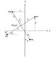
도 5는 위치추정 알고리듬을 나타내기 위한 좌표도이다.5 is a coordinate diagram for illustrating a location estimation algorithm.
도 5를 참조하면, x-y 좌표는 랜드마크(210)의 4개의 영구자석(211)에 대한 좌표이다. 4개의 점(P1, P2, P3, P4)은 모바일 로봇(500)에 부착된 4개의 홀 센서(577)의 위치를 나타낸다. 모바일 로봇(500)의 중심점 좌표를 P라 할 때, x-y 좌표의 원점으로부터 중심점 P의 좌표 (x,y)와 기울기 θ를 구한다.Referring to FIG. 5, the x-y coordinates are coordinates for four
중심점 P에서 각 점(P1, P2, P3, P4)의 거리를l1,l2라 하고, 점 P1의 x축과의 오프셋을 a, 점 P2의 y축과의 오프셋을 b, 점 P3의 x축과의 오프셋을 c, 점 P4의 x축과의 오프셋을 d라 할 때, 중심점 P의 좌표 (x,y)와 기울기 θ는 다음과 같다.The distance of each point (P1, P2, P3, P4) from the center point P isl1 ,l2 , the offset from the x-axis of point P1 is a, the offset from the y-axis of point P2 is b, and the When c is offset from the x-axis and d is offset from the x-axis of the point P4, the coordinates (x, y) and the slope θ of the center point P are as follows.


a, b, c, d 는 영구자석의 좌표와 에이전트 좌표 사이의 차이이다. x, y는 목표도달 위치와 오차 위치 사이의 거리를 나타낸다. θ는 모바일 로봇(500)의 목표 도달 기준 좌표와 실제 좌표의 각도 차이를 나타낸다. 따라서 모바일 로봇(500)이 목표 지점에 도착하였을 때, 실제 위치와 도달 위치 사이의 오차값이 측정되고, 다음 이동 목표 위치의 좌표를 수정하게 된다.a, b, c, d is the difference between the permanent magnet coordinates and the agent coordinates. x and y represent the distance between the target delivery position and the error position. θ represents an angle difference between the target arrival reference coordinate and the actual coordinate of the
여기서는 모바일 로봇(500)의 위치를 보정하기 위해 홀 센서를 사용하고 있으나, 본 발명의 기술적 사상은 이에 한정되지 않는다. 일 실시예로, 모바일 로봇(500)의 경로를 따라 마그네틱 선을 스테이지 유닛(200)에 매설하고, 모바일 로봇(500)이 상기 마그네틱 선을 따라 가면서 위치를 보정하도록 할 수 있다. 다른 실시예로, 스테이지 유닛(200)의 상부 측으로 이격되어 카메라를 설치하고, 카메라를 통해 모바일 로봇(500)의 위치를 실시간으로 추적하도록 할 수 있다.Here, although the Hall sensor is used to correct the position of the
한편, 스테이지 유닛(200) 상에서 모바일 로봇(500)의 절대적인 위치뿐만 아니라, 모바일 로봇(500)의 위치를 초기화할 필요가 있다. 또한, 모바일 로봇(500)의 소형화를 위해 배터리가 내장되는데, 배터리의 충전도 필요하다.On the other hand, it is necessary to initialize not only the absolute position of the
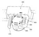
도 6은 모바일 로봇이 도킹 유닛에 진입하는 예를 나타낸다.6 shows an example in which the mobile robot enters the docking unit.
도 6을 참조하면, 도킹유닛(400)은 고정된 기준 그립퍼(410)과 수평으로 이동하는 이동 그립퍼(420)를 포함한다. 기준 그립퍼(410)는 스테이지 유닛(200)에 고정되어, 모바일 로봇(500)의 적어도 일면과 접촉하여 기준 위치를 잡는다. 이동 그립퍼(420)는 모바일 로봇(500)의 적어도 일면과 접촉한다. 즉, 이동 그립퍼(420)가 이동함에 따라 모바일 로봇(500)은 미끄러져, 기준 그립퍼(410)와의 사이에 끼워진다.Referring to FIG. 6, the
이동 그립퍼(420)를 이동시키기 위해 잘 알려진 직선 구동 메커니즘을 사용할 수 있다. 예를 들어, 공압 액츄에이터, 리니어 모터, 벨트 풀리 구조, 볼 스크류 등이 사용될 수 있다.A well known linear drive mechanism can be used to move the
이동 그립퍼(420)의 내측면(모바일 로봇(500)의 일면과 접촉하는 면)에는 충전 단자(425)가 마련된다. 이동 그립퍼(420)가 모바일 로봇(500)과 접촉함에 따라 충전 단자(425)는 모바일 로봇(500)의 충전 커넥터(553)와 접촉하여 모바일 로봇(500)의 배터리를 충전시킨다. 즉, 도킹 유닛(400)은 모바일 로봇(500)의 위치를 초기화할 뿐 아니라, 충전 기능도 수행한다. 여기서, 충전 단자(425)는 이동 그립 퍼(420)에 장착되고 있으나, 충전 단자(425)는 기준 그립퍼(410)에 장착될 수 있고, 또는 이동 그립퍼(420)와 기준 그립퍼(410) 모두에 장착될 수 있다.The charging
초기에 기준 그립퍼(410)와 이동 그립퍼(420)는 떨어져 있다. 모바일 로봇(500)이 도킹 유닛(400)에 근접하여, 기준 그립퍼(410)와 이동 그립퍼(420) 사이로 진입한다. 이동 그립퍼(420)가 기준 그립퍼(410) 측으로 이동함에 따라, 모바일 로봇(500)도 이동 그립퍼(420)와 접촉하여 이동한다. 이동 그립퍼(420)와 모바일 로봇(500)이 접촉함에 따라, 충전 단자(425)와 충전 커넥터(553)도 접촉한다.Initially, the
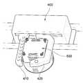
도 7은 도킹 유닛에 도킹된 모바일 로봇을 나타낸다.7 shows a mobile robot docked in a docking unit.
도 7을 참조하면, 도킹 유닛(400)의 기준 그립퍼(410)와 이동 그립퍼(420) 사이에 모바일 로봇(500)이 끼워져, 설정된 위치에서 도킹 유닛(400)과 모바일 로봇(500)이 접속된 상태이다. 모바일 로봇(500)이 기준 그립퍼(410)와 이동 그립퍼(420)에서 고정되면, 모바일 로봇(500)의 위치를 초기화하고, 이를 원점으로 한다. 도킹 유닛(400)과 모바일 로봇(500)이 접속되면 전원단자(425)를 통해 모바일 로봇(500)의 배터리가 충전된다.Referring to FIG. 7, the
도킹 유닛(400)에 의해 모바일 로봇(500)의 기준 위치를 설정할 수 있다. 주기적 또는 비주기적으로 모바일 로봇(500)이 도킹 유닛(400)을 경유하도록 함으로써 위치 오차로 인한 시스템의 에러를 최소화할 수 있다.A reference position of the
도 8은 도 1의 이송 유닛을 확대한 사시도이다.8 is an enlarged perspective view of the transfer unit of FIG. 1.
도 8을 참조하면, 이송 유닛(600)은 이송 로봇(610), 참조 로봇(620) 및 플레이트 승강부(630)를 포함한다.Referring to FIG. 8, the
이송 로봇(610)은 수평(X-Y) 및 수직(Z)으로 이동가능하며, 플레이트(P)와 시료/시약을 운반한다. 이송 로봇(610)은 XZ 구동부(611)와 XZ 구동부(611)에 연결되어 내측으로 연장되는 아암(612) 및 아암(612) 일측에 배치되는 플레이트 이송부(615)와 시료/시약 이송부(616)를 포함한다. XZ 구동부(611)는 X축과 Z축(수직)으로 이동 가능하다. 아암(612)은 XZ 구동부(611)에 연결되어 이동하고, Y축으로 신축된다.The
아암(612)의 일측에는 플레이트 이송부(615)와 시료/시약 이송부(616)가 장착된다. 플레이트 이송부(615)는 플레이트 승강부(630)로부터 공급된 플레이트(P)를 모바일 로봇(500)에 안착시키고, 또는 모바일 로봇(500)에 안착된 플레이트(P)를 배출구(240)로 버린다. 배출구(240)는 스테이지 유닛(200)의 상부에 마련된 홀로, 임상 시험이 완료된 플레이트(P)를 처리한다. 시료/시약 이송부(616)는 적재부(230)에 적재된 다수의 시험관으로부터 시료/시약을 추출하여, 플레이트(P)로 분배한다. 분배부(230)는 스테이지 유닛(200)의 상부에 마련되어 다수의 시험관이 배치된다. 다수의 시험관에는 시료 또는 시약이 적재된다.On one side of the
참조 로봇(620)는 진입하는 모바일 로봇(500)을 고정시켜, 이송 로봇(610)이 플레이트(P)를 안전하게 모바일 로봇(500)에 안착시키도록 한다. 참조 로봇(620)은 2개의 핑거(621, 622)로 구성되어, 2개의 핑거(621, 622) 사이로 모바일 로봇(500)이 진입하며, 적어도 하나의 핑거를 이동하여 모바일 로봇(500)을 고정한다.The
플레이트 승강부(630)는 스테이지 유닛(200) 내부에 장착되어, 스테이지 유닛(200) 내부에 적재된 플레이트(P)를 하나씩 공급한다.The
이제 임상 시험 장치의 동작에 대해 기술한다.The operation of the clinical trial device will now be described.
임상 시험 장치는 시약과 시료의 적재, 시료 식별, 임상 시험에 대한 스케줄링, 시료와 시약의 분주, 이송, 인큐베이션, 측정을 수행한다.Clinical trial devices perform loading of reagents and samples, sample identification, scheduling for clinical trials, dispensing, transport, incubation, and measurement of samples and reagents.
처음으로 시료와 시약이 담겨있는 시험관을 적재부(230)에 적재한다. 모바일 로봇(500)은 도킹 유닛(400)에서 초기화된다. RFID 시스템을 이용하여 시료를 식별한다. 사용자는 각 시료의 임상 시험에 대한 스케줄링을 입력한다.For the first time, a test tube containing a sample and a reagent is loaded in the
임상 시험이 개시되면 모바일 로봇(500)은 이송 유닛(600)의 참조 로봇(620)으로 이동하여, 참조 로봇(620)에 의해 대기 위치에서 대기한다. 플레이트 승강부(630)로부터 공급된 플레이트(P)에 이송 로봇(610)이 시료 및 시약을 분주한다. 이송 로봇(610)은 플레이트(P)를 모바일 로봇(500)에 안착시킨다.When the clinical trial is initiated, the
모바일 로봇(500)은 플레이트(P)를 시험 스테이션(300)으로 이송한다. 시험 스테이션(300) 내에서 모바일 로봇(500)의 진단 모듈(520)에 장착된 검출기(525)에 의해서 임상 시험 결과를 산출한다.The
임상 시험을 종료한 후 모바일 로봇(500)은 도킹 유닛(400)으로 돌아가, 초기 위치를 잡고, 충전을 개시한다.After completing the clinical trial, the
모바일 로봇에 통합되어 있는 진단 모듈을 통해 임상 시험을 수행함으로써 검사 과정을 단축할 수 있다. 또한 다수의 모바일 로봇을 통해 다수의 임상 시험을 진행할 수 있으므로, 병렬적인 검사가 가능하다.Diagnostic modules integrated into the mobile robot can speed up the testing process by conducting clinical trials. In addition, multiple clinical trials can be carried out with multiple mobile robots, enabling parallel testing.
모바일 로봇이 임상 시험 도중 고장이 나더라도, 쉽게 다른 모바일 로봇으로 대체가 가능하므로 전체 시스템의 수율에 영향을 미치지 않게 된다.If a mobile robot fails during a clinical trial, it can easily be replaced by another mobile robot, without affecting the overall system yield.
상술한 모든 기능은 상기 기능을 수행하도록 코딩된 소프트웨어나 프로그램 코드 등에 따른 마이크로프로세서, 제어기, 마이크로제어기, ASIC(Application Specific Integrated Circuit) 등과 같은 프로세서에 의해 수행될 수 있다. 상기 코드의 설계, 개발 및 구현은 본 발명의 설명에 기초하여 당업자에게 자명하다고 할 것이다.All of the above functions may be performed by a processor such as a microprocessor, a controller, a microcontroller, an application specific integrated circuit (ASIC), or the like according to software or program code coded to perform the function. The design, development and implementation of the code will be apparent to those skilled in the art based on the description of the present invention.
이상 본 발명에 대하여 실시예를 참조하여 설명하였지만, 해당 기술 분야의 통상의 지식을 가진 자는 본 발명의 기술적 사상 및 영역으로부터 벗어나지 않는 범위 내에서 본 발명을 다양하게 수정 및 변경시켜 실시할 수 있음을 이해할 수 있을 것이다. 따라서 상술한 실시예에 한정되지 않고, 본 발명은 이하의 특허청구범위의 범위 내의 모든 실시예들을 포함한다고 할 것이다.Although the present invention has been described above with reference to the embodiments, it will be apparent to those skilled in the art that the present invention may be modified and changed in various ways without departing from the spirit and scope of the present invention. I can understand. Therefore, the present invention is not limited to the above-described embodiment, and the present invention will include all embodiments within the scope of the following claims.
도 1은 임상 시험 장치를 나타낸 사시도이다.1 is a perspective view of a clinical trial apparatus.
도 2는 모바일 로봇을 나타낸 분해 사시도이다.2 is an exploded perspective view showing a mobile robot.
도 3은 모바일 로봇의 밑면을 나타낸 사시도이다.3 is a perspective view showing the bottom of the mobile robot.
도 4는 스테이지 유닛에 배치되는 랜드마크를 나타낸다.4 shows a landmark arranged in the stage unit.
도 5는 위치추정 알고리듬을 나타내기 위한 좌표도이다.5 is a coordinate diagram for illustrating a location estimation algorithm.
도 6은 모바일 로봇이 도킹 유닛에 진입하는 예를 나타낸다.6 shows an example in which the mobile robot enters the docking unit.
도 7은 도킹 유닛에 도킹된 모바일 로봇을 나타낸다.7 shows a mobile robot docked in a docking unit.
도 8은 도 1의 이송 유닛을 확대한 사시도이다.8 is an enlarged perspective view of the transfer unit of FIG. 1.
Claims (10)
Translated fromKoreanApplications Claiming Priority (2)
| Application Number | Priority Date | Filing Date | Title |
|---|---|---|---|
| KR1020060065662 | 2006-07-13 | ||
| KR20060065662 | 2006-07-13 |
Publications (2)
| Publication Number | Publication Date |
|---|---|
| KR20080007127A KR20080007127A (en) | 2008-01-17 |
| KR100874519B1true KR100874519B1 (en) | 2008-12-16 |
Family
ID=38923439
Family Applications (1)
| Application Number | Title | Priority Date | Filing Date |
|---|---|---|---|
| KR1020070069992AExpired - Fee RelatedKR100874519B1 (en) | 2006-07-13 | 2007-07-12 | Mobile robot and clinical test device using the same |
Country Status (3)
| Country | Link |
|---|---|
| US (1) | US8641970B2 (en) |
| KR (1) | KR100874519B1 (en) |
| WO (1) | WO2008007923A1 (en) |
Families Citing this family (83)
| Publication number | Priority date | Publication date | Assignee | Title |
|---|---|---|---|---|
| US8222048B2 (en) | 2007-11-05 | 2012-07-17 | Abbott Laboratories | Automated analyzer for clinical laboratory |
| KR101704193B1 (en)* | 2015-04-29 | 2017-02-08 | 목포대학교산학협력단 | The operating system of mobile robot having cross-shaped magnetic position sensor unit |
| EP4582813A3 (en) | 2015-06-26 | 2025-08-27 | Abbott Laboratories | Rotating device in a diagnostic analyzer |
| EP3314269A4 (en) | 2015-06-26 | 2019-01-23 | Abbott Laboratories | Reaction vessel exchanger device for a diagnostic analyzer |
| JP1551868S (en)* | 2015-12-01 | 2016-06-13 | ||
| USD896858S1 (en)* | 2017-12-14 | 2020-09-22 | The Hi-Tech Robotic Systemz Ltd | Mobile robot |
| USD907084S1 (en)* | 2017-12-14 | 2021-01-05 | The Hi-Tech Robotic Systemz Ltd | Mobile robot |
| USD906390S1 (en)* | 2017-12-14 | 2020-12-29 | The Hi-Tech Robotic Systemz Ltd | Mobile robot |
| USD879851S1 (en)* | 2017-12-29 | 2020-03-31 | Beijing Geekplus Technology Co., Ltd. | Robot |
| US10863668B2 (en)* | 2017-12-29 | 2020-12-15 | Dcentralized Systems, Inc. | Autonomous mobile platform with harvesting system and pest and weed suppression systems |
| USD888790S1 (en)* | 2018-01-18 | 2020-06-30 | Lingdong Technology (Beijing) Co.Ltd | Autonomy transportation vehicle |
| US11045811B2 (en) | 2018-02-02 | 2021-06-29 | HighRes Biosolutions, Inc. | Robotic processing system |
| US10955430B2 (en) | 2018-02-02 | 2021-03-23 | HighRes Biosolutions, Inc. | Auto-navigating robotic processing vehicle |
| USD918978S1 (en)* | 2018-04-17 | 2021-05-11 | Beijing Jingdong Qianshi Technology Co., Ltd. | Selecting robot (first generation) |
| USD911406S1 (en)* | 2018-08-17 | 2021-02-23 | Grey Orange Pte. Ltd | Robot for moving articles within a facility |
| USD890828S1 (en)* | 2018-09-19 | 2020-07-21 | Amazon Technologies, Inc. | Mobile conveyor unit |
| USD899475S1 (en)* | 2018-10-31 | 2020-10-20 | Hangzhou Hikrobot Technology Co., Ltd | Automatic guided transport vehicle |
| USD890239S1 (en)* | 2018-11-14 | 2020-07-14 | Grey Orange Pte. Ltd. | Modular cross belt sortation machine |
| USD915486S1 (en)* | 2018-12-31 | 2021-04-06 | Toyota Research Institute, Inc. | Virtual mobility robot |
| USD888791S1 (en)* | 2019-01-07 | 2020-06-30 | Lingdong Technology (Beijing) Co. Ltd | Logistic vehicle |
| USD924291S1 (en)* | 2019-01-18 | 2021-07-06 | Tata Consultancy Services Limited | Industrial robot |
| USD914780S1 (en)* | 2019-02-01 | 2021-03-30 | Hilti Aktiengesellschaft | Mobile jobsite robot |
| JP1646794S (en)* | 2019-03-14 | 2019-12-02 | ||
| JP1646793S (en)* | 2019-03-14 | 2019-12-02 | ||
| JP1646798S (en)* | 2019-03-14 | 2019-12-02 | ||
| JP1646800S (en)* | 2019-03-14 | 2019-12-02 | ||
| JP1646797S (en)* | 2019-03-14 | 2019-12-02 | ||
| JP1646795S (en)* | 2019-03-14 | 2019-12-02 | ||
| JP1646796S (en)* | 2019-03-14 | 2019-12-02 | ||
| JP1646799S (en)* | 2019-03-14 | 2019-12-02 | ||
| USD892188S1 (en)* | 2019-04-05 | 2020-08-04 | IAM Robotics, LLC | Autonomous mobile robot |
| USD908153S1 (en)* | 2019-06-24 | 2021-01-19 | 6 River Systems, Llc | Mobile cart |
| USD908152S1 (en)* | 2019-06-24 | 2021-01-19 | 6 River Systems, Llc | Mobile cart |
| USD909442S1 (en)* | 2019-07-25 | 2021-02-02 | Lingdong Technology (Beijing) Co. Ltd | Logistic vehicle |
| USD909441S1 (en)* | 2019-09-25 | 2021-02-02 | Lingdong Technology (Beijing) Co. Ltd | Logistic vehicle |
| USD991997S1 (en)* | 2020-04-07 | 2023-07-11 | W. Gessman GmbH | Transfer robot |
| USD1060455S1 (en)* | 2019-10-07 | 2025-02-04 | W. Gessmann Gmbh | Transfer robot |
| USD965656S1 (en)* | 2019-10-14 | 2022-10-04 | Omron Corporation | Mobile robot |
| USD976976S1 (en)* | 2019-12-09 | 2023-01-31 | Zebra Technologies Corporation | Mobile automation apparatus |
| USD937920S1 (en)* | 2019-12-19 | 2021-12-07 | Toyota Research Institute, Inc. | Virtual mobility robot |
| USD931922S1 (en)* | 2020-03-06 | 2021-09-28 | Grey Orange Pte. Ltd. | Modular sortation machine |
| USD960950S1 (en)* | 2020-03-31 | 2022-08-16 | Omron Corporation | Mobile robot |
| USD968492S1 (en)* | 2020-05-29 | 2022-11-01 | Blue Ocean Robotics Aps | UV-light disinfection robot |
| USD1018617S1 (en)* | 2020-08-13 | 2024-03-19 | Opex Corporation | Automated storage and retrieval vehicle |
| USD989143S1 (en)* | 2020-08-24 | 2023-06-13 | Hangzhou Hikrobot Co., Ltd. | Automated guided transport vehicle |
| USD963720S1 (en)* | 2020-09-15 | 2022-09-13 | Lingdong Technology (Beijing) Co.Ltd | Logistic vehicle |
| JP1698187S (en)* | 2020-12-21 | 2021-10-25 | ||
| USD967883S1 (en)* | 2021-01-06 | 2022-10-25 | Grey Orange International Inc. | Robot for handling goods in a facility |
| AU2022244220A1 (en)* | 2021-03-26 | 2023-10-12 | Boston Dynamics, Inc. | An integrated mobile manipulator robot with accessory interfaces |
| CA3214801A1 (en)* | 2021-03-26 | 2022-09-29 | Boston Dynamics, Inc. | An integrated mobile manipulator robot |
| USD1040204S1 (en)* | 2021-07-16 | 2024-08-27 | Sintai Optical (Shenzhen) Co., Ltd. | Mobile drive unit |
| USD978943S1 (en)* | 2021-09-10 | 2023-02-21 | Farobot Inc. | Robot |
| USD978944S1 (en)* | 2021-09-17 | 2023-02-21 | Farobot Inc. | Robot |
| USD1031804S1 (en)* | 2021-09-29 | 2024-06-18 | Hyundai Motor Company | Cargo box for portable robot |
| WO2023081778A1 (en)* | 2021-11-04 | 2023-05-11 | Access Medical Systems, Ltd. | Autonomous robotic system for biochemical testing in healthcare environments |
| CA207815S (en)* | 2021-11-12 | 2023-07-18 | Attabotics Inc | Robotic shuttle |
| USD1077008S1 (en)* | 2021-12-17 | 2025-05-27 | Ocado Innovation Limited | Load handling device |
| USD1042572S1 (en)* | 2021-12-22 | 2024-09-17 | Hyundai Motor Company | Docking device for a mobile robot |
| USD1077007S1 (en)* | 2022-01-19 | 2025-05-27 | Ocado Innovation Limited | Load handling device |
| JP1731454S (en)* | 2022-05-31 | 2022-12-06 | automated guided vehicle | |
| JP1731381S (en)* | 2022-05-31 | 2022-12-06 | automated guided vehicle | |
| JP1731453S (en)* | 2022-05-31 | 2022-12-06 | automated guided vehicle | |
| USD1064018S1 (en)* | 2022-06-27 | 2025-02-25 | Shanghai Quicktron Intelligen Technology Co., Ltd | Transfer robot |
| USD1067952S1 (en) | 2022-07-11 | 2025-03-25 | Amazon Technologies, Inc. | Mobile drive unit |
| USD1034729S1 (en)* | 2022-08-10 | 2024-07-09 | Boston Dynamics, Inc. | Robotic device |
| USD1018621S1 (en)* | 2022-08-10 | 2024-03-19 | Boston Dynamics, Inc. | Robotic device |
| USD1034728S1 (en) | 2022-08-10 | 2024-07-09 | Boston Dynamics, Inc. | Robotic device |
| USD1033501S1 (en) | 2022-08-10 | 2024-07-02 | Boston Dynamics, Inc. | Robotic device |
| USD1013001S1 (en)* | 2022-08-10 | 2024-01-30 | Boston Dynamics, Inc. | Robotic device |
| JP1734318S (en)* | 2022-08-22 | 2023-01-12 | Autonomous cart | |
| JP1738275S (en)* | 2022-10-14 | 2023-03-06 | transport robot | |
| KR102551955B1 (en)* | 2022-11-02 | 2023-07-05 | 주식회사 에프원소프트 | Cloud-based clinical data management system |
| USD1088083S1 (en)* | 2023-03-27 | 2025-08-12 | Beijing Youzhuju Network Technology Co., Ltd. | Robot |
| JP1762492S (en)* | 2023-04-07 | 2024-01-29 | autonomous mobile robot | |
| JP1762491S (en)* | 2023-04-07 | 2024-01-29 | autonomous mobile robot | |
| USD1054467S1 (en)* | 2023-04-20 | 2024-12-17 | Beijing Geekplus Technology Co., Ltd. | Transfer robot |
| USD1084078S1 (en)* | 2024-01-09 | 2025-07-15 | Saha Robotik Ve Teslimat Teknolojileri Anonim Sirketi | Service robot |
| USD1052635S1 (en)* | 2024-04-18 | 2024-11-26 | Xtend Ai Inc. | Modular robot with drawer inserts |
| USD1052633S1 (en)* | 2024-04-18 | 2024-11-26 | Xtend Ai Inc. | Modular robot with open cabinet and shelves |
| USD1052631S1 (en)* | 2024-04-18 | 2024-11-26 | Xtend Ai Inc. | Modular robot with closed cabinet and shelves |
| USD1072013S1 (en)* | 2024-12-05 | 2025-04-22 | Chang Industrial, LLC | Autonomous cart body |
| USD1072014S1 (en)* | 2024-12-05 | 2025-04-22 | Chang Industrial, LLC | Autonomous cart body |
| USD1073760S1 (en)* | 2025-01-21 | 2025-05-06 | Chang Robotics, Llc | Autonomous cart body |
Citations (2)
| Publication number | Priority date | Publication date | Assignee | Title |
|---|---|---|---|---|
| US5623415A (en) | 1995-02-16 | 1997-04-22 | Smithkline Beecham Corporation | Automated sampling and testing of biological materials |
| US6374989B1 (en) | 1997-11-14 | 2002-04-23 | Bayer Corporation | Conveyor system for clinical test apparatus |
Family Cites Families (9)
| Publication number | Priority date | Publication date | Assignee | Title |
|---|---|---|---|---|
| JPH04134262A (en) | 1990-09-27 | 1992-05-08 | Shimadzu Corp | Specimen sampling method |
| US6429016B1 (en)* | 1999-10-01 | 2002-08-06 | Isis Pharmaceuticals, Inc. | System and method for sample positioning in a robotic system |
| US6534014B1 (en)* | 2000-05-11 | 2003-03-18 | Irm Llc | Specimen plate lid and method of using |
| SE518683C2 (en)* | 2001-03-15 | 2002-11-05 | Electrolux Ab | Method and apparatus for determining the position of an autonomous apparatus |
| US7648678B2 (en)* | 2002-12-20 | 2010-01-19 | Dako Denmark A/S | Method and system for pretreatment of tissue slides |
| WO2004083806A2 (en)* | 2003-01-22 | 2004-09-30 | University Of South Florida | Autonomous genosensor apparatus and methods for use |
| US20040191923A1 (en)* | 2003-03-31 | 2004-09-30 | Tomasso David Angelo | Test element holder with a probe guide for an analyzer |
| US7729801B2 (en)* | 2004-02-03 | 2010-06-01 | F Robotics Acquisitions Ltd. | Robot docking station and robot for use therewith |
| KR100690669B1 (en)* | 2005-05-17 | 2007-03-09 | 엘지전자 주식회사 | Position Recognition System of Autonomous Robot |
- 2007
- 2007-07-12KRKR1020070069992Apatent/KR100874519B1/ennot_activeExpired - Fee Related
- 2007-07-13USUS12/162,131patent/US8641970B2/ennot_activeExpired - Fee Related
- 2007-07-13WOPCT/KR2007/003406patent/WO2008007923A1/enactiveApplication Filing
Patent Citations (2)
| Publication number | Priority date | Publication date | Assignee | Title |
|---|---|---|---|---|
| US5623415A (en) | 1995-02-16 | 1997-04-22 | Smithkline Beecham Corporation | Automated sampling and testing of biological materials |
| US6374989B1 (en) | 1997-11-14 | 2002-04-23 | Bayer Corporation | Conveyor system for clinical test apparatus |
Also Published As
| Publication number | Publication date |
|---|---|
| US8641970B2 (en) | 2014-02-04 |
| KR20080007127A (en) | 2008-01-17 |
| WO2008007923A1 (en) | 2008-01-17 |
| US20090035181A1 (en) | 2009-02-05 |
Similar Documents
| Publication | Publication Date | Title |
|---|---|---|
| KR100874519B1 (en) | Mobile robot and clinical test device using the same | |
| EP2298509A1 (en) | Carrier device, position-teaching method, and sensor jig | |
| KR100936085B1 (en) | Wireless substrate-like sensor | |
| US10890596B2 (en) | Sampling probes, systems, apparatuses, and methods | |
| TWI459010B (en) | Electronic component carrying device and electronic component carrying method | |
| US20230146784A1 (en) | Compact clinical diagnostics system with planar sample transport | |
| JP4607848B2 (en) | Substrate processing apparatus, substrate delivery position adjusting method, and storage medium | |
| CN103042531A (en) | An apparatus for gripping and holding diagnostic cassettes | |
| KR102023655B1 (en) | Transfer apparatus, transfer method, exposure apparatus, and device manufacturing method | |
| EP1721171B1 (en) | Magnetically attractive specimen-container rack for automated clinical instrument | |
| JP5184121B2 (en) | 2D sample handler | |
| JP5959138B2 (en) | Semiconductor wafer handling equipment | |
| CN114245767A (en) | Robot hand, robot system, and transfer method | |
| US20050194237A1 (en) | Magnetic specimen-transport system for automated clinical instrument | |
| US7724007B2 (en) | Probe apparatus and probing method | |
| US9372080B2 (en) | Adjustment system for a transfer system in an in-vitro diagnostics system | |
| CN110211889A (en) | Inspection system | |
| CN207866839U (en) | A kind of magnetic microparticle chemiluminescence immune assay instrument puma manipulator | |
| JP7730913B2 (en) | Apparatus and method for aligning components of a diagnostic laboratory system - Patent Application 20070122997 | |
| US7361920B2 (en) | Substrate processing apparatus and transfer positioning method thereof | |
| Fazal et al. | Multi-Modal Sensor for Fingertips of Anthropomorphic Grippers | |
| ES2898175T3 (en) | Adjustment system. | |
| Choi et al. | Development of robotic laboratory automation platform with intelligent mobile agents for clinical chemistry | |
| Choi et al. | Development of flexible laboratory automation platform using mobile agents in the clinical laboratory | |
| CN118922251A (en) | Incorporating functional units into modules of an automated diagnostic analysis system to increase functionality thereof |
Legal Events
| Date | Code | Title | Description |
|---|---|---|---|
| A201 | Request for examination | ||
| PA0109 | Patent application | St.27 status event code:A-0-1-A10-A12-nap-PA0109 | |
| PA0201 | Request for examination | St.27 status event code:A-1-2-D10-D11-exm-PA0201 | |
| R18-X000 | Changes to party contact information recorded | St.27 status event code:A-3-3-R10-R18-oth-X000 | |
| PG1501 | Laying open of application | St.27 status event code:A-1-1-Q10-Q12-nap-PG1501 | |
| E701 | Decision to grant or registration of patent right | ||
| PE0701 | Decision of registration | St.27 status event code:A-1-2-D10-D22-exm-PE0701 | |
| GRNT | Written decision to grant | ||
| PR0701 | Registration of establishment | St.27 status event code:A-2-4-F10-F11-exm-PR0701 | |
| PR1002 | Payment of registration fee | St.27 status event code:A-2-2-U10-U11-oth-PR1002 Fee payment year number:1 | |
| PG1601 | Publication of registration | St.27 status event code:A-4-4-Q10-Q13-nap-PG1601 | |
| FPAY | Annual fee payment | Payment date:20110916 Year of fee payment:4 | |
| PR1001 | Payment of annual fee | St.27 status event code:A-4-4-U10-U11-oth-PR1001 Fee payment year number:4 | |
| PN2301 | Change of applicant | St.27 status event code:A-5-5-R10-R11-asn-PN2301 | |
| PN2301 | Change of applicant | St.27 status event code:A-5-5-R10-R11-asn-PN2301 | |
| PN2301 | Change of applicant | St.27 status event code:A-5-5-R10-R14-asn-PN2301 | |
| FPAY | Annual fee payment | Payment date:20120511 Year of fee payment:6 | |
| PR1001 | Payment of annual fee | St.27 status event code:A-4-4-U10-U11-oth-PR1001 Fee payment year number:5 | |
| R18-X000 | Changes to party contact information recorded | St.27 status event code:A-5-5-R10-R18-oth-X000 | |
| R18-X000 | Changes to party contact information recorded | St.27 status event code:A-5-5-R10-R18-oth-X000 | |
| PN2301 | Change of applicant | St.27 status event code:A-5-5-R10-R13-asn-PN2301 St.27 status event code:A-5-5-R10-R11-asn-PN2301 | |
| PN2301 | Change of applicant | St.27 status event code:A-5-5-R10-R11-asn-PN2301 | |
| PN2301 | Change of applicant | St.27 status event code:A-5-5-R10-R13-asn-PN2301 St.27 status event code:A-5-5-R10-R11-asn-PN2301 | |
| R18-X000 | Changes to party contact information recorded | St.27 status event code:A-5-5-R10-R18-oth-X000 | |
| PN2301 | Change of applicant | St.27 status event code:A-5-5-R10-R14-asn-PN2301 | |
| LAPS | Lapse due to unpaid annual fee | ||
| PC1903 | Unpaid annual fee | St.27 status event code:A-4-4-U10-U13-oth-PC1903 Not in force date:20141211 Payment event data comment text:Termination Category : DEFAULT_OF_REGISTRATION_FEE | |
| PC1903 | Unpaid annual fee | St.27 status event code:N-4-6-H10-H13-oth-PC1903 Ip right cessation event data comment text:Termination Category : DEFAULT_OF_REGISTRATION_FEE Not in force date:20141211 | |
| PN2301 | Change of applicant | St.27 status event code:A-5-5-R10-R13-asn-PN2301 St.27 status event code:A-5-5-R10-R11-asn-PN2301 | |
| PN2301 | Change of applicant | St.27 status event code:A-5-5-R10-R13-asn-PN2301 St.27 status event code:A-5-5-R10-R11-asn-PN2301 | |
| R18-X000 | Changes to party contact information recorded | St.27 status event code:A-5-5-R10-R18-oth-X000 |