KR100873316B1 - Method and device for controlling and expanding multiple video devices - Google Patents
Method and device for controlling and expanding multiple video devicesDownload PDFInfo
- Publication number
- KR100873316B1 KR100873316B1KR1020027016119AKR20027016119AKR100873316B1KR 100873316 B1KR100873316 B1KR 100873316B1KR 1020027016119 AKR1020027016119 AKR 1020027016119AKR 20027016119 AKR20027016119 AKR 20027016119AKR 100873316 B1KR100873316 B1KR 100873316B1
- Authority
- KR
- South Korea
- Prior art keywords
- dvrc
- video
- video signals
- dvr
- network
- Prior art date
- Legal status (The legal status is an assumption and is not a legal conclusion. Google has not performed a legal analysis and makes no representation as to the accuracy of the status listed.)
- Expired - Fee Related
Links
Images

Classifications
- H—ELECTRICITY
- H04—ELECTRIC COMMUNICATION TECHNIQUE
- H04N—PICTORIAL COMMUNICATION, e.g. TELEVISION
- H04N7/00—Television systems
- H04N7/18—Closed-circuit television [CCTV] systems, i.e. systems in which the video signal is not broadcast
- H—ELECTRICITY
- H04—ELECTRIC COMMUNICATION TECHNIQUE
- H04N—PICTORIAL COMMUNICATION, e.g. TELEVISION
- H04N5/00—Details of television systems
- H04N5/76—Television signal recording
- H04N5/765—Interface circuits between an apparatus for recording and another apparatus
- H04N5/77—Interface circuits between an apparatus for recording and another apparatus between a recording apparatus and a television camera
- H—ELECTRICITY
- H04—ELECTRIC COMMUNICATION TECHNIQUE
- H04N—PICTORIAL COMMUNICATION, e.g. TELEVISION
- H04N5/00—Details of television systems
- H04N5/76—Television signal recording
- H04N5/765—Interface circuits between an apparatus for recording and another apparatus
- H—ELECTRICITY
- H04—ELECTRIC COMMUNICATION TECHNIQUE
- H04N—PICTORIAL COMMUNICATION, e.g. TELEVISION
- H04N5/00—Details of television systems
- H04N5/76—Television signal recording
- H04N5/765—Interface circuits between an apparatus for recording and another apparatus
- H04N5/775—Interface circuits between an apparatus for recording and another apparatus between a recording apparatus and a television receiver
- H—ELECTRICITY
- H04—ELECTRIC COMMUNICATION TECHNIQUE
- H04N—PICTORIAL COMMUNICATION, e.g. TELEVISION
- H04N9/00—Details of colour television systems
- H04N9/79—Processing of colour television signals in connection with recording
- H04N9/80—Transformation of the television signal for recording, e.g. modulation, frequency changing; Inverse transformation for playback
- H04N9/804—Transformation of the television signal for recording, e.g. modulation, frequency changing; Inverse transformation for playback involving pulse code modulation of the colour picture signal components
- H04N9/8042—Transformation of the television signal for recording, e.g. modulation, frequency changing; Inverse transformation for playback involving pulse code modulation of the colour picture signal components involving data reduction
Landscapes
- Engineering & Computer Science (AREA)
- Multimedia (AREA)
- Signal Processing (AREA)
- Closed-Circuit Television Systems (AREA)
- Television Signal Processing For Recording (AREA)
- Signal Processing For Digital Recording And Reproducing (AREA)
- Testing, Inspecting, Measuring Of Stereoscopic Televisions And Televisions (AREA)
- Testing And Monitoring For Control Systems (AREA)
- Studio Devices (AREA)
- Two-Way Televisions, Distribution Of Moving Picture Or The Like (AREA)
Abstract
Translated fromKoreanDescription
Translated fromKorean본 발명은 일반적으로 복수의 비디오 입력 장치들을 제어하기 위한 방법 및 시스템에 관한 것으로, 보다 구체적으로는, 복수의 비디오 카메라들로부터의 비디오 정보에 대한 중앙 제어(centralized controlling) 및 다중화된 기록(multiplexed recording) 및 선택적인 디스플레이를 위한 제어 스테이션에 관한 것이다.FIELD OF THE INVENTION The present invention generally relates to a method and system for controlling a plurality of video input devices, and more particularly to centralized controlling and multiplexed recording of video information from a plurality of video cameras. And a control station for optional display.
일군의 빌딩들에 설치되는 일반적인 비디오 감시 시스템에 있어서는 각 빌딩 내 미리결정된 위치들에 복수의 아날로그 비디오 카메라들이 배치될 것이며 하나 이상의 디지털 비디오 기록장치들(DVR)은 빌딩의 복수의 비디오 카메라들의 비디오를 기록 및/또는 선택적으로 디스플레이하기 위해 각 빌딩 내에 배치될 수 있다. 주어진 빌딩 내 복수의 카메라들로부터의 비디오는 그 빌딩 내 또는 그 빌딩에서 원격지에 있는 중앙 보안 감시 영역에서 볼 수 있다.In a typical video surveillance system installed in a group of buildings, a plurality of analog video cameras will be placed at predetermined locations within each building, and one or more digital video recorders (DVRs) will display video from a plurality of video cameras in the building. It can be placed in each building for recording and / or for optional display. Video from multiple cameras in a given building can be viewed in a central security surveillance area within or remote from the building.
이를테면 필립스 CSIs 4-채널 및 16-채널 DVR들과 같은 디지털 비디오 기록장치들(DVR)에 직접 유선으로 연결된 복수의(예를 들면 4개 또는 16개) 아날로그 비디오 카메라들에 의해 발생된 비디오 신호들의 프로그램된 선택을 기록하는 데에 이러한 DVR들이 흔히 사용된다. 단일의 제어 스테이션으로부터 복수의 디지털 비디오 기록장치들(DVR)을 시청하고 제어하는 현재의 방법들은 이들 DVR들 각각을 이를테면 필립스 LTC 2605/90 System4 비디오 관리기와 같은 특별한 외부 비디오 스위칭 장치, 또는 개인용 컴퓨터에 접속하는 것을 포함한다. 이러한 구성에서, 비디오 신호들 및 제어 신호들은 별도의 구별되는 라인들을 통해 전달될 것이며, 예를 들면 비디오는 복수의 동축 케이블들을 통해 아날로그 신호들로서 각 DVR에서 관리기로 전송될 수 있으며, 제어 신호들은 디지털 직렬 유선 접속을 통해 각 DVR에서 관리기로 전달될 수 있다. 각각의 디지털 비디오 기록장치(DVR)는 빌딩의 서로 다른 룸 내에 또는 완전히 별도의 빌딩 내에 있을 수 있다. 그리고 각 DVR은 이러한 관리기에 직접 유선으로 연결되어야 한다. 따라서, 복수의 공간적으로 분리된 DVR들을 단일의 관리기에 동작이 되게 접속하는 것은 복수의 긴 비디오 케이블들을 관리기에 잇는 것을 포함할 수 있고, 사용자들(예를 들면, 보안 직원)은 관리기의 단일의 위치에서 모든 비디오 채널들을 보고 제어할 수 있을 뿐이다.For example, video signals generated by multiple (eg four or sixteen) analog video cameras directly wired to digital video recorders (DVR), such as Philips CSIs 4-channel and 16-channel DVRs. These DVRs are commonly used to record programmed choices. Current methods of viewing and controlling a plurality of digital video recorders (DVRs) from a single control station may be directed to each of these DVRs, such as a special external video switching device such as the Philips LTC 2605/90 System4 video manager, or a personal computer. It involves connecting. In this configuration, the video signals and the control signals will be carried on separate distinct lines, for example video may be sent to each manager in each DVR as analog signals via a plurality of coaxial cables, the control signals being digital It can be delivered from each DVR to the manager via a serial wired connection. Each digital video recorder (DVR) may be in a different room of a building or in a completely separate building. Each DVR must be wired directly to this manager. Thus, operatively connecting a plurality of spatially separated DVRs to a single manager may include connecting a plurality of long video cables to the manager, such that users (eg, security personnel) You can only see and control all the video channels in place.
따라서, 본 발명의 제 1 특징은 네트워크상의 적어도 하나의 다른 장치, 이를테면 다른 DVRC(디지털 비디오 기록기-제어기 장치), DVR(예를 들면, 슬레이브 모드로 동작하는 DVRC), 개인용 컴퓨터, 또는 심지어는 이더넷 카메라에 DVRC를 통신 가능하게 접속하기 위한 네트워크 포트를 포함하는 디지털 비디오 기록기-제어기 장치(DVRC)를 제공하며, 여기서 DVRC는 디지털화된 비디오 신호들의 제1 선택을 네트워크 포트를 통해 전송하도록 구성되고, 제1 선택은 네트워크상의 다른 제1 장치, 이를테면 다른 DVRC나 개인용 컴퓨터에 전송되는 하나 이상의 디지털화된 비디오 신호들을 포함할 수 있고, DVRC는 디지털화된 비디오 신호들의 제2 선택을 네트워크 포트를 통해 수신하도록 또한 구성되며, 제2 선택은 네트워크상의 다른 제 2 장치, 이를테면 다른 DVRC, DVR, 또는 이더넷 카메라에 의해 전송되는 하나 이상의 디지털화된 비디오 신호들을 포함할 수 있고, DVRC는 또한 제2 선택의 디지털화된 비디오 신호들의 지정을 용이하게 하도록 구성되어 있다. DVRC는 또한 제1 선택 또는 제2 선택의 하나 이상의 디지털화된 비디오 신호들을 디스플레이하도록 구성된 복수의 비디오-아웃 포트들, 및 제1 선택 및 제2 선택의 디지털화된 비디오 신호들의 지정을 용이하게 하도록 구성된 적어도 하나의 제어 패널을 포함할 수 있다.Thus, a first feature of the invention is that at least one other device on the network, such as another DVRC (digital video recorder-controller device), DVR (eg, DVRC operating in slave mode), personal computer, or even Ethernet A digital video recorder-controller device (DVRC) comprising a network port for communicatively connecting a DVRC to a camera, wherein the DVRC is configured to send a first selection of digitized video signals through a network port, and The first selection may comprise one or more digitized video signals transmitted to another first device on the network, such as another DVRC or personal computer, wherein the DVRC is further configured to receive a second selection of digitized video signals through the network port. And the second choice is another second device on the network, such as another DVRC, DVR, or Ethernet may comprise one or more digitized video signals transmitted by the camera, DVRC is also configured to facilitate the designation of the digitized video signal of the second selection. The DVRC also includes a plurality of video-out ports configured to display one or more digitized video signals of the first selection or the second selection, and at least configured to facilitate designation of the digitized video signals of the first selection and the second selection. One control panel may be included.
본 발명의 제2 특징은 네트워크와, 네트워크상의 디지털 비디오 기록기-제어기 장치(DVRC)에 동작 가능하게 접속된 복수의 제1 비디오 카메라들과, 네트워크상의 디지털 비디오 기록기(DVR)에 동작 가능하게 접속된 복수의 제2 비디오 카메라들을 포함하는 디지털 비디오 시스템을 제공한다. DVR은 네트워크에서 DVRC에 DVR을 통신 가능하게 상호 접속하기 위한 네트워크 포트를 구비한다. DVR은 디지털화된 비디오 신호들의 선택을 네트워크 포트를 통해 전송하도록 구성되며, 상기 디지털화된 비디오 신호들의 선택은 포함한다. DVR은 하나 이상의 DVR 모니터들에 하나 이상의 비디오 신호들의 디스플레이를 용이하게 하도록 구성된 복수의 비디오-아웃 포트들을 더 포함할 수 있다. DVRC는 DVR의 모든 특징들과 하드웨어를 포함할 수 있고, 또한 DVRC는 DVR에 의해서 또는 네트워크상의 어떤 다른 비디오-전송 장치에 의해 전송된 하나 이상의 디지털화된 비디오 신호들을 포함할 수 있는 다른 선택의 디지털화된 비디오 신호들을 제1 네트워크 포트를 통해 수신하도록 구성된다. DVRC는 또한 네트워크상의 다른 비디오-전송 장치로의 제어 신호들의 전송을 용이하게 하기 위해, 키보드(즉, 외부 제어 패널) 또는 다른 외부 제어 장치용의 외부 제어 포트와 내장된 제어 패널 모두 또는 둘 중 어느 하나를 포함할 수도 있다.A second aspect of the invention is a network, a plurality of first video cameras operatively connected to a digital video recorder-controller device (DVRC) on the network, and a operatively connected to a digital video recorder (DVR) on the network. A digital video system comprising a plurality of second video cameras is provided. The DVR has a network port for communicatively interconnecting the DVR to the DVRC in the network. The DVR is configured to send a selection of digitized video signals through a network port, the selection of which is included. The DVR may further include a plurality of video-out ports configured to facilitate display of one or more video signals on one or more DVR monitors. The DVRC may include all the features and hardware of the DVR, and the DVRC may also include one or more digitized video signals that may include one or more digitized video signals transmitted by the DVR or by any other video-transmitting device on the network. And receive video signals through a first network port. The DVRC also provides an external control port for the keyboard (i.e., an external control panel) or other external control device and an embedded control panel, or both, to facilitate the transmission of control signals to other video-transmitting devices on the network. It may also include one.
본 발명의 제3 특징은 DVRC 네트워크 포트를 구비한 적어도 한 디지털 비디오 기록기-제어기 장치(DVRC), 및 적어도 한 제어 패널을 제공하는 것을 포함하는 디지털 비디오 시스템 확장 방법을 제공한다. 각각의 DVRC는 이의 DVRC 네트워크 포트를 통해서 디지털화된 비디오 신호들의 선택된 것을 수신하도록 구성되고 하나 이상의 비디오 신호들을 하나 이상의 비디오 모니터들에 디스플레이를 용이하게 하도록 충분한 수의 DVRC 비디오-아웃 포트들을 구비할 것이다. DVRC는 비디오 카메라들에 직접 아니면 동작 가능하게 접속하기 위한 하나 이상의 DVRC 비디오-인 포트들을 더 포함할 수 있다.A third aspect of the present invention provides a method of extending a digital video system comprising providing at least one digital video recorder-controller device (DVRC) having a DVRC network port, and at least one control panel. Each DVRC is configured to receive a selection of digitized video signals through its DVRC network port and will have a sufficient number of DVRC video-out ports to facilitate display of one or more video signals on one or more video monitors. The DVRC may further include one or more DVRC video-in ports for direct or operatively connecting to video cameras.
도 1은 제1 DVRC가, 슬레이브 모드로 동작하는 다른 DVRC들 및/또는 DVR들을 원격 제어하는 마스터 모드로 동작하는 본 발명의 디지털 비디오 기록기-제어기(DVRC)의 이더넷 네트워크의 간략화된 블록도.1 is a simplified block diagram of an Ethernet network of a digital video recorder-controller (DVRC) of the present invention in which the first DVRC operates in master mode for remotely controlling other DVRCs and / or DVRs in slave mode.
도 2는 본 발명의 실시예들에 따른 단일 디지털 비디오 기록기-제어기(DVRC)의 간략화된 블록도.2 is a simplified block diagram of a single digital video recorder-controller (DVRC) in accordance with embodiments of the present invention.
본 발명의 실시예들은 별도의 관리기의 필요성을 제거하며, 각각의 DVR을 네트워크상의 모든 다른 비디오 기록 장치들(DVR들)을 이더넷 네트워크를 통해 제어하도록 구성함으로써, 각 DVR의 사이트에 컴퓨터에 의존하지 않는 제어 스테이션을 제공한다. 그러므로 디지털 비디오 및 제어 신호들은 어떠한 외부 관리기들, 컴퓨터들 및/또는 특별한 비디오 스위치들의 필요성도 없이 본 발명의 디지털 비디오 기록기-제어기(DVRC)간에 이더넷을 통해 전송될 수 있다.Embodiments of the present invention eliminate the need for a separate manager and configure each DVR to control all other video recording devices (DVRs) on the network via an Ethernet network, thereby avoiding a computer dependency on the site of each DVR. Does not provide a control station. Therefore digital video and control signals can be transmitted via Ethernet between the digital video recorder-controller (DVRC) of the present invention without the need for any external managers, computers and / or special video switches.
각각의 DVRC는 제공된 네트워크 포트(예를 들면, 이더넷 네트워크 포트)를 포함하며, 네트워크상의 임의의 하나의 DVRC가 다른 네트워크된 DVRC들 또는 DVR들이 "슬레이브" 장치들로서 동작하는 동안 "마스터"로서 동작하는 것을 허용하는 하드웨어 및/또는 소프트웨어를 포함할 수 있다. DVRC는 동시에 마스터 및 슬레이브로서 동작할 수 있다. 마스터 DVRC는 제어 신호들을 슬레이브 장치들(예를 들면, 슬레이브 모드로 동작하는 DVR들 및/또는 DVRC들)에 보내며, 마스터는 제공된 네트워크 포트(예를 들면, 이더넷 인터페이스)를 통해 내내 슬레이브 DVRC들로부터 비디오를 수신, 복호, 및 디스플레이한다. 대안으로, 모든 DVRC들은 네트워크를 통해 외부 제어 스테이션(예를 들면, 관리기)에 의한 제어를 위해, 이를테면 네트워크된 PC에 의한 제어를 위해 또는 보다 원격으로 이를테면 원격 인터넷 기반의 제어 스테이션에 의한 제어를 위해 슬레이브들로서 구성될 수 있다. 본 발명의 DVRC들은 기존의 이더넷 스위치들, 케이블들, 및/또는 허브들을 통해 상호 접속될 수 있다.Each DVRC includes a provided network port (eg, an Ethernet network port), and any one DVRC on the network acts as a "master" while other networked DVRCs or DVRs operate as "slave" devices. Hardware and / or software that allows the data to be included. The DVRC can operate as a master and a slave at the same time. The master DVRC sends control signals to slave devices (e.g., DVRs and / or DVRCs operating in slave mode), and the master receives from slave DVRCs throughout the provided network port (e.g., Ethernet interface). Receive, decode, and display video. Alternatively, all DVRCs may be controlled by an external control station (eg, a manager) via a network, such as by a networked PC or more remotely, such as by a remote Internet-based control station. It can be configured as slaves. The DVRCs of the present invention may be interconnected via existing Ethernet switches, cables, and / or hubs.
도 1은 상업적으로 이용 가능한 이더넷 스위치(410)를 통해 이더넷 네트워크에 접속된 본 발명에 따른 N(N은 정수)개의 디지털 비디오 기록기 제어기들(예를 들면, DVRC-1, DVRC-2,...,DVRC-N)을 포함하는 비디오 감시 시스템(100)을 도시한 간략화된 블록도이다. 각 DVRC(예를 들면, DVRC-1, DVRC-2,...,DVRC-N)은 이의 직접 접속된 비디오 카메라들(310)의 비디오 신호들을 이더넷 네트워크상의 어떤 다른 DVRC에 이러한 비디오 이미지들의 원격 기록 및/또는 디스플레이를 위해 송신할 수 있다. 반대로, 각 DVRC(예를 들면, DVRC-1)는 이더넷으로부터 다른 DVRC들에 의해 전송된 비디오 신호들을 수신할 수 있다. 각 DVRC는 "라이브" 비디오 신호들을 송신 및/또는 디스플레이하는 바와 동일한 방식으로 저장된(즉, 이전에 기록된) 비디오 데이터를 전송 및/또는 디스플레이하도록 구성될 수 있다.1 shows N (N is an integer) digital video recorder controllers (e.g., DVRC-1, DVRC-2, ..) according to the present invention connected to an Ethernet network via a commercially available Ethernet
제1 DVRC(DVRC-1)는 슬레이브 모드로 동작하는 적어도 하나의 다른 DVRC(예를 들면, DVRC-2,...DVRC-N)을 원격으로 제어하는(및/또는 기 시판중의 적어도 하나의 필립스 DVR을 원격으로 제어하는) '마스터'(즉, 제어) 모드로 동작되는 것으로서 도시되었다. (슬레이브 모드로 동작하는 DVRC들은 DVR의 모든 기능적 특징들을 구비할 수 있고, DVR들이 비디오 감시 시스템(100)에서 몇몇 슬레이브 모드 DVRC들과 교체 가능하다.)The first DVRC (DVRC-1) remotely controls (and / or at least one on the market) at least one other DVRC (e.g., DVRC-2, ... DVRC-N) operating in slave mode. The remote control of the Philips DVR is shown as operating in 'master' (ie control) mode. (The DVRCs operating in slave mode may have all the functional features of the DVR, and the DVRs are interchangeable with some slave mode DVRCs in the
시스템(100) 내 DVRC들(예를 들면, DVRC-1, DVRC-2,...,DVRC-3) 각각은 직접 접속되거나(예를 들면 동축 비디오 케이블을 통해) 아니면, 도 1에 도시한 바와 같이 각각의 DVRC가 j개의(예를 들면, j는 도 1에 도시된 각각의 예시적인 DVRC에 대해 4개임) 복수의 비디오 카메라들(310)에 직접 접속되는, 적어도 한 비디오 카메라(310)에 동작적으로 접속될 수 있다(예를 들면, 무선 비디오 방송을 통해서). 도 1에 DVRC당 상수로서(즉, j=4) j개의 아날로그 비디오 카메라들(310)을 도시하고 있으나, 카메라들(310)의 수 j는 각 DVRC에 얼마나 많은 아날로그 비디오-인 포트들이 갖추어져 있는가에 따라서, 그리고 얼마나 많은 비디오 카메라들(310)을 사용자가 DVRC 비디오-인 포트들에 접속하였는가에 따라서 시스템(100) 내 각 DVRC마다 다를 수도 있다. 예를 들면 디지털 카메라들만을 접속하는 대안으로서의 실시예들에서, 아날로그 카메라 수(예를 들면, j)는 제로일 수 있다. 비디오 카메라들(310)은 다양한 시판중의 아날로그 비디오 카메라들 중에서 선택될 수 있고 각 카메라를 이들의 각각의 DVRC들 상의 비디오-인 포트들에 긴 동축 케이블들에 의해 접속하여 빌딩 또는 사이트 도처에 공간적으로 분산배치될 수 있다. 각 비디오 카메라(310)는 이 비디오 카메라로부터의 무선-주파수 비디오 방송과 같은 무선 접속을 통해 하나 이상의 DVR들 및/또는 DVRC들에 동작적으로 접속될 수 있음을 알 것이다. 비디오 신호원들(310)을 여기서는 "비디오 카메라들"로서 기술하였으나, 이를테면 스틸-카메라들, 타임-랩스 카메라들, 적외 센서들, 자외 센서들, 엑스레이 센서들, 소나, 레이다, 현미경 카메라들, 또는 컴퓨터로 생성되는 이미지 데이터와 같이 어떤 다른 2차원 이미지 소스, 또는 어떤 다른 프레임 기반의 데이터 스트림으로부터의 신호들은 사용자의 애플리케이션들이 명시하는 바대로 본 발명의 DVRC에 의해 수신되고 디스플레이되고 및/또는 기록될 수 있음을 알 것이다. 물론, 오디오 신호들 및 그 외 다른 동시에 발생된 데이터 신호들(예를 들면, 카메라(310)로부터의 움직임 검출기 알람, 상태 데이터, 또는 연관된 하드웨어에 의해 발생된 신호들)은 본 발명의 DVRC에 의해 동시에 수신되고 비디오 신호들과 함께 디스플레이되고 및/또는 기록될 수 있으며, 여기서 "비디오 신호들"이라는 것은 이러한 어떤 오디오 신호들 및 동시 발생된 데이터 신호들을 포함할 것이다. "비디오 장치"라는 용어는 비디오 신호들을 수신하여 디스플레이 및/또는 수신하여 기록하는, DVR 및 DVRC를 포함하는 장치를 포함한다.Each of the DVRCs (e.g., DVRC-1, DVRC-2, ..., DVRC-3) in the
각 DVRC는 j개의 아날로그 비디오-인 접속기들 및/또는 j개의 아날로그 비디오 카메라들에 접속하기 위한 무선 수신 포트들을 포함할 것이다. 또한, DVRC에 접속되는 비디오 카메라들 일부 또는 전부는 디지털 비디오 카메라들(310D, 예를 들면 도 2에서 디지털 카메라들(310D-1, 310D-k) 참조)일 수 있고, k(k는 정수)개의 디지털 비디오 카메라들을 접속하기 위한 적합한 수의 접속기들 및 디지털 포트들은 DVRC에 제공될 것이다. 디지털 비디오-인 포트들은 유니버설 직렬 버스(USB), 이더넷 포트, 파이어와이어 포트(fire wire port) 등과 같은 어떤 적합한 디지털 포트일 수 있다. (k개의 복수의 디지털 비디오 카메라들(310D)이 단일 포트(예를 들면, USB 또는 이더넷 포트)를 통해 DVRC에 접속된다면 이 복수의 디지털 카메라들로부터 k개의 디지털화된 비디오 신호들 전부를 수신하기에 충분할 수 있다). 각각의 DVRC는 이 DVRC에 직접 또는 동작 가능하게 접속된 복수의(예를 들면, j 또는 j+k) 비디오 카메라 각각으로부터 수신된 비디오 신호들을 기록( 및 디지털화 및/또는 압축)하는 능력을 갖추고 있을 것이다. 또한, 각각의 DVRC는 이에 복수의 직접 접속된 비디오 카메라들(예를 들면 310) 각각으로부터 수신된 비디오 신호들을 디지털화, 압축, 부호화하여 이더넷 네트워크상의 원격장치, 이를테면 또 다른 DVRC, 및/또는 개인용 컴퓨터에 송신한다. 이더넷 네트워크상의 DVR들(도시없음)에 의해서 또는 DVRC들(예를 들면, DVRC-2)에 의해 전송된 비디오 신호들은 적어도 한 외부 비디오 디스플레이 모니터(500)(예를 들면, 500-1 및/또는 500-2), 또는 집적 비디오-디스플레이 모니터(도시없음)에 동작적으로 접속되는 이더넷 네트워크상의 어떤 다른 DVRC에 원격으로 디스플레이될 수 있다.Each DVRC may include j analog video-in connectors and / or wireless receive ports for connecting to j analog video cameras. In addition, some or all of the video cameras connected to the DVRC may be
각각의 DVRC는 최대 M개(M은 정수)의 아날로그 또는 디지털 비디오 디스플레이 모니터들(500), 예를 들면 폐쇄회로 텔레비전 세트, 텔레비전, 컴퓨터 모니터들, LCD 패널들 등에 M 하드웨어(비디오-아웃) 포트들, 접속기들 및 이 기술에 숙련된 자들에 공지된 방식으로 설치된 케이블링을 통해 접속될 수 있다. 주어진 DVRC(예를 들면, DVRC-1)의 M개의 비디오-아웃 포트들에 접속될 수 있는 M개의 복수의 비디오-디스플레이모니터들 각각은 시스템(100)의 네트워크상의 어떤 DVR(도시없음) 또는 DVRC(예를 들면, DVRC-2 및/또는 DVRC-N)에 접속된 하나 이상의 비디오 카메라들(301)로부터 전송된 비디오 신호들을 디스플레이할 수 있다. 예를 들면, 모니터(500-1)는 DVRC-1에 직접 접속된 한 비디오 카메라(310)로부터의 풀-스크린 비디오 이미지들을 디스플레이할 수 있는 반면, 쿼드-모드(quad-mode)로 동작하는 모니터(500-2)는 DVRC-2에 직접 접속된 어떤 두 개의 카메라들의 비디오 신호들과 더불어 DVRC-N에 직접 접속된 임의의 두 카메라들의 비디오 신호들을 동시에 디스플레이할 수 있다. 모니터(500-2) 상에 디스플레이되는 4개의 비디오 신호들 각각은 이 모니터(500-2)의 화면의 미리지정된 또는 동적으로 선택된 화면의 부분에 디스플레이될 것이다. 각각의 DVRC는 각각의 부착된 모니터(500)가 m-모드에서 m개의 비디오 카메라들(310)까지의 비디오 신호들을 동시에 디스플레이하도록 동작될 수도 있게, 결합된 비디오 신호들을 출력하도록 구성될 수 있다. 주어진 모니터(500) 상에 디스플레이되는 m개의 비디오 신호들은 시스템(100) 내의 임의의 DVRC에 직접 또는 동작 가능하게 접속된 카메라들(310)로부터의 모든 비디오 신호들로부터 선택된 비디오 신호들의 선택일 수 있다. 다른 예와 같이, 쿼드-모드에서 동작하며 DVRC-2에 직접 접속된 모니터(500, 도시되지않음)는 DVRC-2에 직접 또는 동작 가능하게 접속된 임의의 하나 이상의 카메라들(310)의 비디오 신호들과 DVRC-N에 직접 또는 동작 가능하게 접속된 임의의 하나 이상의 비디오 카메라들(310)의 비디오 신호들과, DVRC-1에 직접 또는 동작 가능하게 접속된 임의의 하나 이상의 비디오 카메라들(310)의 비디오 신호들을 동시에 디스플레이할 수 있다.Each DVRC has a M hardware (video-out) port for up to M (M is integer) analog or digital video display monitors 500, e.g., closed circuit television sets, televisions, computer monitors, LCD panels, etc. , Connectors and cabling can be connected in a manner known to those skilled in the art. Each of the M plurality of video-display monitors, which may be connected to the M video-out ports of a given DVRC (e.g., DVRC-1), is any DVR (not shown) or DVRC on the network of the
각각의 DVRC는 시스템(100) 내 임의의 DVR 또는 DVRC에 직접 또는 동작 가능하게 접속될 수 있는 모든 V개의(예를 들면, V = N x j 또는 V=N x (j+k), 또는 일반적으로,

시스템 내 N개의 DVRC들 중 어느 하나에 의해 디스플레이 및/또는 기록할 비디오 신호들의 선택은 "마스터" 모드로 동작하는 동안의 임의의 DVRC에 의해 프로그램되어 제어될 수 있다.The selection of video signals to display and / or record by any one of the N DVRCs in the system can be programmed and controlled by any DVRC while operating in the " master " mode.
마스터 모드로 동작하는 DVCR(예를 들면, DVCR-1)는, 다른 (슬레이브) DVRC 또는 DVR이 j+k 카메라들(310 및 310D)로부터의 명시된 비디오 신호들(선택된 채널들)을 전송 및/또는 디스플레이하거나, 시스템(100)의 네트워크상의 다른 DVR들 또는 DVRC들로부터 수신된 비디오 신호들을 디스플레이 및/또는 기록하도록 명령하여, 슬레이브 모드로 동작하는 DVRC(예를 들면, DVRC-2, 또는 DVRC-N)에 (이더넷 스위치(410)를 통해서) 이더넷 네트워크상에 전해지는 제어 신호를 발급한다. 마스터 DVRC에 의해 발생된 제어 신호에 응답하여, 수신 DVR(또는 슬레이브-모드 DVRC들)은, 그가 그의 접속된 카메라들(310)로부터 또는 시스템(100)의 네트워크상의 다른 DVR들 또는 DVRC들로부터 수신하는 비디오 신호들의 명시된 선택을 전송, 디스플레이 및/또는 기록하도록 프로그램된다. 이 방식으로, 제1 슬레이브-모드 DVRC(또는 DVR)는 특정의 제2 슬레이브-모드 DVRC에 선택된 비디오 신호를 전송하도록 마스터-모드 DVRC에 의해 지시를 받을 수 있고, 제2 슬레이브-모드 DVRC도 마찬가지로 선택된 비디오 신호를 디스플레이하고 기록하도록 지시를 받을 수 있다.DVCR (e.g., DVCR-1) operating in master mode is characterized in that another (slave) DVRC or DVR transmits specified video signals (selected channels) from j +
(임의의 DVRC에서의 전송, 디스플레이 및/또는 기록을 위해) 비디오 신호들의 선택을 용이하게 하고 임의의 다른 DVRC(예를 들면, 슬레이브 모드로 동작하는 지정된 DVRC들 및/또는 DVR들)의 동작들(예를 들면, 전송, 디스플레이 및/또는 기록)의 원격 제어를 용이하게 하기 위해서, 도 1에 DVRC-1에 접속된 것으로 도시된 바와 같이 지정된 "마스터" DVRC 상의 외부 제어 포트에 외부 제어 키보드(212)가 영구적으로 고정 또는 착탈 가능하게 부착 또는 동작 가능하게 무선으로 접속될 수 있다. 내장 제어 패널 또는 외부 제어 패널(예를 들면, 외부 제어 포트를 통해 접속된 외부 제어 키보드(212), 이것은 기본적으로 내장 제어 패널의 기능을 갖는 외부 제어 패널임)은 네트워크상의 다른 장치에 의해 DVRC에 전송될 하나 이상의 디지털화된 비디오 신호들을 지정하는데 사용될 수 있다. 여기서 사용되는 "제어 패널"이라는 용어는 "외부 제어 포트"를 근본적으로 오디오 마이크 또는 비디오 카메라로 구성한 이를테면 오디오 음성 인식 기반의 또는 비디오 립-리딩 기반의 사용자 명령 해석 회로와 같은 종래의 및 비-종래의 등가물들을 포함한다.Operations of any other DVRC (e.g., designated DVRCs and / or DVRs operating in slave mode) to facilitate the selection of video signals (for transmission, display and / or recording on any DVRC) To facilitate remote control of (e.g., transmit, display and / or record), an external control keyboard (with an external control port on the designated "master" DVRC as shown connected to DVRC-1 in FIG. 212 can be permanently fixed or detachably attached or operatively connected wirelessly. The built-in control panel or external control panel (e.g., an
이러한 내장 제어 패널, 외부 제어 포트 및/또는 외부 제어 키보드(212)가 동작 가능하게 부착되는 임의의 DVRC는 마스터-모드 DVRC로서 동작될 수 있다. 이 기술에 숙련된 자들은 사용자들이 주어진 시스템(100)에 하나 이상의 제어 패널 및/또는 하나 이상의 마스터-모드 DVRC를 사용하거나 사용하려고 할 가능성을 처리하기 위해서 중재 방법 또는 슬레이브-모드 디폴트 프로토콜들을 제공할 수도 있다. 시스템(100) 내 카메라들(310)로부터의 비디오 신호들을 선택하고 시스템(100) 내 임의의 DVRC들 및/또는 DVR들의 원격제어를 하기 위해서 제어 키보드(22) 상의 키, 다이얼, 디스플레이 및 제어가 선택, 조종 및 최적화될 수 있다. 제어 키보드(212)는 모든 실시예들에서 모든 "쿼티(qwerty)"(알파벳) 키들을 포함할 필요는 없으나 라벨들, 주석, 및 명령라인들의 입력을 위한 키들을 포함할 수 있다. 제어 키보드(212)에는 시스템(10) 내 비디오 카메라들(310)을 이동시키거나 겨냥하기 위해서 제공되는 임의의 로보틱 팬-틸트형 기구들의 제어 및 조종(maneuvering)이 용이하게 되도록 조이스틱형 레버 또는 유사한 피봇 장치가 제공될 수도 있다. 기구식 제어 패널(예를 들면, 제어 키보드(212))에 대한 대안들은 이들이 사람 음성 명령 해석 제어 모듈들(도시없음) 또는 인공지능(AI) 및/또는 광학 패턴(예를 들면, 얼굴, 파이어, 모션) 인식 트리거들을 탑재한 프로그램 가능한 제어장치들(도시없음)을 포함할 수 있어, 이들이 이 기술에 숙련된 자들로부터 사용자들이 활용할 수 있게 될 때 대용으로 사용될 수 있다.Any DVRC to which this built-in control panel, external control port and / or
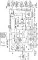
도 2는 본 발명의 실시예들에 따른 단일의 디지털 비디오 기록기 제어기(DVRC) 내 예시적인 내부회로들의 간략화된 기능 블록도를 도시한 것이다. 각각의 본 발명의 DVRC의 전술한 특징, 기능 및 동작은 본 발명의 DVRC들의 특징, 기능, 및 동작의 수행을 제공 및/또는 지시하도록 구성된 적합한 소프트웨어 제품들을 포함하여, 도 2에 도시한 장치와 같은 각종의 마이크로프로세서 기반의 장치로 구현될 수 있다. 필립스사의 모델 DMX-16과 같은, 원격 개인용 컴퓨터의 모니터에 디스플레이하기 위해 비디오 정보를 전송하기 위한 내장된 이더넷 포트들을 포함하는 현존의 마이크로프로세서 기반의 DVR들은, 본 발명의 DVRC들의 개시된 특징들, 기능들 및 동작들의 대부분 또는 모두를 수행할 수 있게 하고 이들을 수행하도록 지시하기 위해 내부 소프트웨어를 변경함으로써, 본 발명의 DVRC로 변형될 수 있을 것으로 생각된다. 따라서, 16 비디오 카메라들(예를 들면, 310-1, 310-2,...310-j, 여기서 j=16)용의 적어도 16-아날로그 비디오 입력 포트들; 제어 신호들을 수신 및/또는 송신하고 디스플레이 및/또는 기록을 위해 비디오 신호들을 수신 및/또는 송신하기 위한 하나의 10베이스-T 또는 하나의 100베이스-T 또는 보다 고속의 이더넷 제어기(241) 및 연관된 포트들; 로컬 비디오 이미지들(동일 DVRC의 접속된 카메라들로부터) 또는 원격 비디오 이미지들(시스템(100)내 이더넷 네트워크상의 다른 DVR들 또는 DVRC들에 접속된 카메라들로부터)의 디스플레이를 위한 적어도 두 개의 모니터들(500)(예를 들면, 500-1, 500-2, 500-3, 500-M)용의 적어도 두 개의 모니터 포트들(비디오-아웃 포트), 75 GB 또는 보다 큰 하드 디스크 드라이브(260), 및 프론트-패널(211) 상의 전용기능 버튼들, 제어 및 디스플레이들, 및 동일 또는 원격지의 DVRC들 및/또는 DVR들의 제어를 위한 외부 제어 키보드(212)를 구비한 본 발명의 DVRC가 쉽게 제작될 수 있다.2 shows a simplified functional block diagram of exemplary internal circuits in a single digital video recorder controller (DVRC) in accordance with embodiments of the present invention. Each of the foregoing features, functions, and operations of the DVRC of the present invention may include suitable software products configured to provide and / or direct the performance, features, and operations of the DVRCs of the present invention. The same may be implemented in various microprocessor-based devices. Existing microprocessor-based DVRs, including built-in Ethernet ports for transmitting video information for display on a monitor of a remote personal computer, such as Philips' Model DMX-16, are the disclosed features, functions of the DVRCs of the present invention. It is contemplated that modifications may be made to the DVRC of the present invention by modifying internal software to enable and / or instruct most or all of the examples and operations. Thus, at least 16-analog video input ports for 16 video cameras (eg, 310-1, 310-2, ... 310-j, where j = 16); One 10 base-T or one 100 base-T or
본 발명의 DVRC의 실시예들은 디지털 프로세서 BUS에 동작 가능하게 결합되는 중앙 프로세서(예를 들면, 디지털 마이크로프로세서 또는 디지털 신호 프로세서(DSP))를 포함한다. 중앙 프로세서(210)는 BUS에 결합되는 비휘발성 메모리에 저장되는 본 발명의 소프트웨어 제품에 제공된 명령들에 따라 동작한다. 소프트웨어 제품을 저장시키기 위한 비휘발성 메모리는 ROM(즉, read only memory) 또는 RAM(Random Access Memory) 또는 BUS에 동작 가능하게 결합되는 디지털 대량 기억장치(예를 들면, IDE HDD 제어기(262)에 의한 하드 디스크 드라이브(260),또는 DVD-RAM 장치(도시없음), 또는 테이프 드라이브(도시없음))일 수 있다.Embodiments of the DVRC of the present invention include a central processor (eg, digital microprocessor or digital signal processor (DSP)) operatively coupled to the digital processor BUS. The
접속된 비디오 카메라들(301 또는 310D)로부터 또는 원격지의 DVRC들로부터 이더넷 제어기(241)를 통해 DVRC에 의해 수신되는 모든 비디오 정보는 프로세서 BUS로 보내질 수 있다. 그러므로, RAM, 및/또는 BUS에 동작 가능하게 결합된 디지털 대량 저장 장치(예를 들면, HDD(260))는 복수의 로컬 및 원격 비디오 카메라들(310)로부터의 비디오 신호 정보를 기록 및 저장하는 DVRC 기능을 수행할 수도 있다.All video information received by the DVRC from the
아날로그 비디오 카메라에 결합된 DVRC는 프론트 패널 제어(211)에 의해서 또는 중앙 프로세서(210)를 통해 제어 키보드(212)에 의해 제어되는 내부 아날로그 비디오 스위치들(231)을 포함할 것이다. 이 기술에 숙련된 자들이 아는 바와 같이, 복수의 아날로그 비디오 카메라들(310)(예를 들면, 310-1, 310-2, 310-3, 310-j)은 각각의 비디오 디지타이저(digitizer; 230)가 메모리 제어기(234) 및 비디오-RAM(236)에 동작 가능하게 결합되는 이 하나 이상의 디지타이저(들)(230)에 결합되는 하나 이상의 비디오 스위치(들)(231)을 포함하는 서브-시스템을 통해 DVRC 내부 프로세서 BUS에 동작 가능하게 결합될 수 있다. 이들 회로들은 시간-베이스 보정(비동기된 아날로그 카메라들을 처리하는데 필요한)을 지원할 수 있다. 메모리 제어기(234)는 접속된 카메라들(310 및 310D)로부터 수신된 선택된 비디오 이미지 정보를 하나 이상의 압축엔진(들)(238)에 송신하며 압축엔진은 비디오 정보의 전송된 바이트들의 수를 공지의 방법들, 이를테면 프레임들 내 및/또는 프레임간 리던던트 정보를 제거하는 MPEG 비디오 압축 알고리즘을 채용함으로써 감소시킨다. 압축엔진(들)(238)은 또한 압축된 비디오의 압축해제를 수행할 수도 있다(예를 들면, 비디오의 로컬 디스플레이를 위해). 압축엔진(238)은 이더넷 제어기(241)를 통해 다른 DVRC들에 의해 원격 디스플레이 및/또는 기록을 위해 저장 및/또는 전송하기 위해서, 및/또는 RAM 및/또는 BUS 상의 디지털 대량 기억장치(예를 들면, HDD(260))에 의한 로컬 저장을 위해서 BUS에 압축된 비디오 데이터를 제공한다. 압축된 디지털화된 비디오 신호들은 복수의 모니터들(500)(예를 들면, 501-1, 500-2, 500-3,...500-M)에 이러한 비디오 신호들의 디스플레이를 위해 압축엔진(238)에 의해 압축해제될 수 있다. 모니터들이 아날로그 모니터들이면, 복수의 디지털 아날로그 변환기들(250)은 이러한 아날로그 모니터들에 디스플레이하기 위해 디지털화된 비디오 신호들을 아날로그 비디오 신호들로 변환하도록 제공될 수 있다.The DVRC coupled to the analog video camera will include internal analog video switches 231 controlled by the
본 발명을 전술한 실시예들에 관련하여 기술되었으나, 많은 대안, 수정 및 변형이 이 기술에 숙련된 자들에게 명백할 것임이 자명하다. 예를 들면, 복수의(예를 들면 N=3) 16채널 DVRC들(예를 들면, 16 아날로그 비디오 카메라들에 접속하기 위한 16 아날로그 비디오-인 포트들을 갖는 DVRC들)이 단일의 위치(예를 들면, 하나의 중앙 보안 및 감시 룸)에 설치되는 경우, 단일의 48채널 DVR처럼 보이게 하고 이와 같이 동작되게 하고 하나의 제어/감시 키보드(212)를 구비하여 이로부터 한 위치에서 모든 접속된 카메라들(310)을 액세스하도록 구성될 수 있다. 네트워크는 "이더넷" 네트워크로 한정될 필요는 없고, 충분한 대역폭을 갖거나 아니면 디지털 비디오 신호들 및 제어 신호들을 전송할 수 있는 어떤 다른 공지의 또는 장래의 디지털 네트워크 기술을 구비할 수 있을 것임을 알 것이다. 이러한 경우, 선택된 네트워크 기술에 적합한 네트워크 포트는 전술한 모든 기능들을 이더넷 포트의 기능들로서 수행하도록 본 발명의 DVRC에 부가되거나 이를 대용할 수 있을 것이다. 따라서, 상기 개시된 본 발명의 실시예들은 예시적인 것이고 한정하려는 것은 아니다. 다음의 청구범위에 정한 본 발명의 정신 및 범위로부터 일탈함이 없이 각종의 변경이 행해질 수 있다.Although the present invention has been described in connection with the foregoing embodiments, it will be apparent that many alternatives, modifications and variations will be apparent to those skilled in the art. For example, a plurality of (e.g., N = 3) 16-channel DVRCs (e.g., DVRCs with 16 analog video-in ports for connecting to 16 analog video cameras) may have a single location (e.g., For example, when installed in one central security and surveillance room, it can look like a single 48-channel DVR and behave like this and have a single control /
Claims (20)
Translated fromKoreanApplications Claiming Priority (3)
| Application Number | Priority Date | Filing Date | Title |
|---|---|---|---|
| US09/819,788 | 2001-03-28 | ||
| US09/819,788US7881585B2 (en) | 2001-03-28 | 2001-03-28 | Multi video device control and expansion method and apparatus |
| PCT/IB2002/000715WO2002080539A2 (en) | 2001-03-28 | 2002-03-11 | Multi video device control and expansion method and apparatus |
Publications (2)
| Publication Number | Publication Date |
|---|---|
| KR20030005416A KR20030005416A (en) | 2003-01-17 |
| KR100873316B1true KR100873316B1 (en) | 2008-12-12 |
Family
ID=25229071
Family Applications (1)
| Application Number | Title | Priority Date | Filing Date |
|---|---|---|---|
| KR1020027016119AExpired - Fee RelatedKR100873316B1 (en) | 2001-03-28 | 2002-03-11 | Method and device for controlling and expanding multiple video devices |
Country Status (7)
| Country | Link |
|---|---|
| US (1) | US7881585B2 (en) |
| EP (1) | EP1374577B1 (en) |
| JP (1) | JP4295990B2 (en) |
| KR (1) | KR100873316B1 (en) |
| AT (1) | ATE469508T1 (en) |
| DE (1) | DE60236500D1 (en) |
| WO (1) | WO2002080539A2 (en) |
Cited By (2)
| Publication number | Priority date | Publication date | Assignee | Title |
|---|---|---|---|---|
| KR101217101B1 (en) | 2011-04-15 | 2012-12-31 | 주식회사 윈포넷 | Digital video recoder with multi-display control function and multi-display control method in the digitall video recoder |
| KR101731592B1 (en)* | 2016-10-17 | 2017-04-28 | 주식회사하이트론씨스템즈 | Multiple video monitoring system for standalone type |
Families Citing this family (31)
| Publication number | Priority date | Publication date | Assignee | Title |
|---|---|---|---|---|
| US7576770B2 (en)* | 2003-02-11 | 2009-08-18 | Raymond Metzger | System for a plurality of video cameras disposed on a common network |
| US7698450B2 (en) | 2000-11-17 | 2010-04-13 | Monroe David A | Method and apparatus for distributing digitized streaming video over a network |
| US7623753B2 (en)* | 2001-10-26 | 2009-11-24 | Robert Bosch Gmbh | Method for viewing and controlling multiple DVR's |
| US7257309B1 (en)* | 2002-03-05 | 2007-08-14 | Avica Technology Corporation | Distributed storage of audio/video content |
| EP1450527B1 (en)* | 2002-04-19 | 2006-10-04 | Yamaha Corporation | Communication management apparatus |
| NZ524757A (en)* | 2003-03-14 | 2006-03-31 | Navman New Zealand | Radar installation |
| KR20040081841A (en)* | 2003-03-17 | 2004-09-23 | 주식회사 성진씨앤씨 | Digital video recorder having a internet phone and communicating method thereof |
| EP1627524A4 (en)* | 2003-03-20 | 2009-05-27 | Ge Security Inc | Systems and methods for multi-resolution image processing |
| US7457670B2 (en) | 2003-08-07 | 2008-11-25 | Production Resource Group, Llc | Gobo virtual machine |
| US20050086321A1 (en)* | 2003-10-21 | 2005-04-21 | Folk Robert H.Ii | Apparatus and method for providing a virtual common hard disk recorder resource |
| US20070247918A1 (en)* | 2004-08-30 | 2007-10-25 | Renesas Technology Corp. | Semiconductor Integrated Circuit |
| US20060176391A1 (en)* | 2005-02-07 | 2006-08-10 | Yi-Jen Cheng | Digital video recorder |
| JP4399809B2 (en)* | 2005-03-11 | 2010-01-20 | 日本ビクター株式会社 | Video recording control system |
| JP4634201B2 (en)* | 2005-04-01 | 2011-02-16 | パナソニック株式会社 | Information network system and information device |
| US20060271975A1 (en)* | 2005-05-23 | 2006-11-30 | Edmund Sun | Time-shifting audio and video programs |
| US7688544B1 (en)* | 2005-05-23 | 2010-03-30 | Seagate Technology Llc | Magnetic heads disk drives and methods with floating pole tip or shunted pole tip for reduced pole tip erasure |
| JP4514724B2 (en)* | 2006-03-22 | 2010-07-28 | 株式会社日立国際電気 | Video storage system |
| US7721313B2 (en) | 2006-06-30 | 2010-05-18 | Microsoft Corporation | Multi-DVR node communication |
| US20080022330A1 (en)* | 2006-06-30 | 2008-01-24 | Microsoft Corporation | Multi-DVR Content Management |
| US20080022331A1 (en)* | 2006-06-30 | 2008-01-24 | Microsoft Corporation | Multi-DVR Media Stream Transition |
| US20080218590A1 (en)* | 2007-03-08 | 2008-09-11 | Sang Jun Park | Method and system for multiple-codec surveillance video storage and retrieval |
| US9654718B2 (en)* | 2008-04-02 | 2017-05-16 | Bose Corporation | Method and apparatus for selecting a signal source |
| US20100077456A1 (en)* | 2008-08-25 | 2010-03-25 | Honeywell International Inc. | Operator device profiles in a surveillance system |
| KR100981591B1 (en)* | 2008-09-05 | 2010-09-13 | (주)아이디스 | DVW system |
| US8379090B1 (en)* | 2008-11-06 | 2013-02-19 | Target Brands, Inc. | Virtual visits |
| KR101045502B1 (en)* | 2009-06-05 | 2011-06-30 | 주식회사 씨. 아이. 테크 | Collective Image Selector |
| US9866609B2 (en)* | 2009-06-08 | 2018-01-09 | Time Warner Cable Enterprises Llc | Methods and apparatus for premises content distribution |
| US10028018B1 (en) | 2011-03-07 | 2018-07-17 | Verint Americas Inc. | Digital video recorder with additional video inputs over a packet link |
| US9734707B2 (en)* | 2012-01-09 | 2017-08-15 | Universal Electronics Inc. | Features for use with a multi-sided controlling device |
| US10379588B2 (en)* | 2016-09-09 | 2019-08-13 | Verint Americas Inc. | System and method of remote power/power over ethernet (POE) device controls |
| US20180357033A1 (en)* | 2017-06-08 | 2018-12-13 | Ve Virtual Environment Llc | Virtual video environment display systems |
Citations (2)
| Publication number | Priority date | Publication date | Assignee | Title |
|---|---|---|---|---|
| KR19980024003A (en)* | 1996-09-06 | 1998-07-06 | 윤종용 | Digital audio / video data transmission device and method |
| KR20000053787A (en)* | 2000-04-12 | 2000-09-05 | 권순도 | Processing System Of Multi-Function Digital Signal |
Family Cites Families (20)
| Publication number | Priority date | Publication date | Assignee | Title |
|---|---|---|---|---|
| CA223764A (en) | 1922-09-19 | Morgan Philip | Phonograph record holder | |
| DE3809129C2 (en)* | 1988-03-18 | 1994-06-09 | Broadcast Television Syst | Method and device for controlling video-technical devices |
| US4963995A (en)* | 1988-12-27 | 1990-10-16 | Explore Technology, Inc. | Audio/video transceiver apparatus including compression means |
| US5930473A (en)* | 1993-06-24 | 1999-07-27 | Teng; Peter | Video application server for mediating live video services |
| JP3090827B2 (en)* | 1993-10-30 | 2000-09-25 | ソニー株式会社 | Transmission signal forming method, bidirectional bus system receiving method, and communication system |
| GB9509616D0 (en) | 1995-05-12 | 1995-07-05 | Baxall Security Ltd | Closed circuit television system |
| US5724475A (en)* | 1995-05-18 | 1998-03-03 | Kirsten; Jeff P. | Compressed digital video reload and playback system |
| US5583796A (en)* | 1995-06-06 | 1996-12-10 | Philips Electronics North America Corporation | Video security backup system |
| US6181867B1 (en)* | 1995-06-07 | 2001-01-30 | Intervu, Inc. | Video storage and retrieval system |
| WO1997008896A1 (en) | 1995-08-23 | 1997-03-06 | Scientific-Atlanta, Inc. | Open area security system |
| US6002995A (en)* | 1995-12-19 | 1999-12-14 | Canon Kabushiki Kaisha | Apparatus and method for displaying control information of cameras connected to a network |
| US6208379B1 (en)* | 1996-02-20 | 2001-03-27 | Canon Kabushiki Kaisha | Camera display control and monitoring system |
| JPH09233412A (en)* | 1996-02-23 | 1997-09-05 | Mitsubishi Electric Corp | Video data recording / playback system |
| JP3309720B2 (en) | 1996-06-25 | 2002-07-29 | ソニー株式会社 | Video system control method |
| EP0895421A3 (en) | 1997-07-29 | 1999-11-17 | Canon Kabushiki Kaisha | Camera control system controlling different types of cameras |
| JP2000278672A (en)* | 1999-01-21 | 2000-10-06 | Matsushita Electric Ind Co Ltd | Network type monitoring device |
| JP2000278633A (en)* | 1999-03-26 | 2000-10-06 | Victor Co Of Japan Ltd | Digital video recorder, digital video recording and reproducing system and digital video recording method |
| US6330025B1 (en)* | 1999-05-10 | 2001-12-11 | Nice Systems Ltd. | Digital video logging system |
| CA2403270C (en)* | 2000-03-14 | 2011-05-17 | Joseph Robert Marchese | Digital video system using networked cameras |
| JP2002078633A (en) | 2000-09-07 | 2002-03-19 | Hitachi Chem Co Ltd | Shower apparatus for bathroom |
- 2001
- 2001-03-28USUS09/819,788patent/US7881585B2/ennot_activeExpired - Fee Related
- 2002
- 2002-03-11DEDE60236500Tpatent/DE60236500D1/ennot_activeExpired - Lifetime
- 2002-03-11JPJP2002577414Apatent/JP4295990B2/ennot_activeExpired - Fee Related
- 2002-03-11ATAT02703790Tpatent/ATE469508T1/ennot_activeIP Right Cessation
- 2002-03-11EPEP02703790Apatent/EP1374577B1/ennot_activeExpired - Lifetime
- 2002-03-11WOPCT/IB2002/000715patent/WO2002080539A2/enactiveApplication Filing
- 2002-03-11KRKR1020027016119Apatent/KR100873316B1/ennot_activeExpired - Fee Related
Patent Citations (2)
| Publication number | Priority date | Publication date | Assignee | Title |
|---|---|---|---|---|
| KR19980024003A (en)* | 1996-09-06 | 1998-07-06 | 윤종용 | Digital audio / video data transmission device and method |
| KR20000053787A (en)* | 2000-04-12 | 2000-09-05 | 권순도 | Processing System Of Multi-Function Digital Signal |
Cited By (3)
| Publication number | Priority date | Publication date | Assignee | Title |
|---|---|---|---|---|
| KR101217101B1 (en) | 2011-04-15 | 2012-12-31 | 주식회사 윈포넷 | Digital video recoder with multi-display control function and multi-display control method in the digitall video recoder |
| KR101731592B1 (en)* | 2016-10-17 | 2017-04-28 | 주식회사하이트론씨스템즈 | Multiple video monitoring system for standalone type |
| WO2018074691A1 (en)* | 2016-10-17 | 2018-04-26 | 주식회사 하이트론씨스템즈 | Stand-alone multiple video surveillance system |
Also Published As
| Publication number | Publication date |
|---|---|
| JP2004523984A (en) | 2004-08-05 |
| US7881585B2 (en) | 2011-02-01 |
| ATE469508T1 (en) | 2010-06-15 |
| US20020141732A1 (en) | 2002-10-03 |
| EP1374577B1 (en) | 2010-05-26 |
| EP1374577A2 (en) | 2004-01-02 |
| DE60236500D1 (en) | 2010-07-08 |
| WO2002080539A2 (en) | 2002-10-10 |
| KR20030005416A (en) | 2003-01-17 |
| JP4295990B2 (en) | 2009-07-15 |
| WO2002080539A3 (en) | 2003-06-05 |
Similar Documents
| Publication | Publication Date | Title |
|---|---|---|
| KR100873316B1 (en) | Method and device for controlling and expanding multiple video devices | |
| EP0738076B1 (en) | Camera control system and method of controlling same | |
| US20020031333A1 (en) | On-the fly video editing device for capturing and storing images from a video stream during playback for subsequent editing and recording | |
| JP4426780B2 (en) | Video recording / reproducing system and recording / reproducing method | |
| EP1654878A1 (en) | Portable surveillance camera and personal surveillance system using the same | |
| JP3996960B2 (en) | Camera control system | |
| KR20030039069A (en) | DVR(Digital Video-audio Recording) System Structured with non PC-based(Stand-alone) Type and Audio Channels | |
| KR20090056423A (en) | Virtual Matrix System and Control Method | |
| US6717611B2 (en) | Multiple channel video recording using a single video bus | |
| KR101924113B1 (en) | A video recorder locally controllable remote video recorders and method for controlling the same | |
| KR100434775B1 (en) | Video and digital recording system | |
| JP2010022028A (en) | Video-monitoring system | |
| CN219018883U (en) | Video segmentation recording system | |
| KR100725384B1 (en) | System keyboard with video input/output function and surveillance system for the system keyboard | |
| KR101365506B1 (en) | Integrated control system for video/audio device | |
| KR100466790B1 (en) | integerated DVR system | |
| JP4421857B2 (en) | Monitoring device and monitoring system | |
| KR200309017Y1 (en) | Matrix Switcher for Digital Video Recorder | |
| JP2001069493A (en) | Comprehensive monitoring system | |
| KR100389532B1 (en) | System for display and record of digital video image with providing analog video image selectively | |
| KR20050064437A (en) | Monitoring system using network camera | |
| KR20090128623A (en) | Surveillance system using DVD device | |
| JPH09252466A (en) | Monitor camera system | |
| HK1117319A (en) | System and method for digital type wireless monitoring | |
| JPH11187381A (en) | Monitor device for building |
Legal Events
| Date | Code | Title | Description |
|---|---|---|---|
| PA0105 | International application | St.27 status event code:A-0-1-A10-A15-nap-PA0105 | |
| PG1501 | Laying open of application | St.27 status event code:A-1-1-Q10-Q12-nap-PG1501 | |
| PN2301 | Change of applicant | St.27 status event code:A-3-3-R10-R11-asn-PN2301 | |
| R19-X000 | Request for party data change rejected | St.27 status event code:A-3-3-R10-R19-oth-X000 | |
| N231 | Notification of change of applicant | ||
| PN2301 | Change of applicant | St.27 status event code:A-3-3-R10-R13-asn-PN2301 St.27 status event code:A-3-3-R10-R11-asn-PN2301 | |
| R17-X000 | Change to representative recorded | St.27 status event code:A-3-3-R10-R17-oth-X000 | |
| R17-X000 | Change to representative recorded | St.27 status event code:A-3-3-R10-R17-oth-X000 | |
| A201 | Request for examination | ||
| P11-X000 | Amendment of application requested | St.27 status event code:A-2-2-P10-P11-nap-X000 | |
| P13-X000 | Application amended | St.27 status event code:A-2-2-P10-P13-nap-X000 | |
| PA0201 | Request for examination | St.27 status event code:A-1-2-D10-D11-exm-PA0201 | |
| R17-X000 | Change to representative recorded | St.27 status event code:A-3-3-R10-R17-oth-X000 | |
| R18-X000 | Changes to party contact information recorded | St.27 status event code:A-3-3-R10-R18-oth-X000 | |
| E902 | Notification of reason for refusal | ||
| PE0902 | Notice of grounds for rejection | St.27 status event code:A-1-2-D10-D21-exm-PE0902 | |
| T11-X000 | Administrative time limit extension requested | St.27 status event code:U-3-3-T10-T11-oth-X000 | |
| T11-X000 | Administrative time limit extension requested | St.27 status event code:U-3-3-T10-T11-oth-X000 | |
| P11-X000 | Amendment of application requested | St.27 status event code:A-2-2-P10-P11-nap-X000 | |
| P13-X000 | Application amended | St.27 status event code:A-2-2-P10-P13-nap-X000 | |
| E701 | Decision to grant or registration of patent right | ||
| PE0701 | Decision of registration | St.27 status event code:A-1-2-D10-D22-exm-PE0701 | |
| GRNT | Written decision to grant | ||
| PR0701 | Registration of establishment | St.27 status event code:A-2-4-F10-F11-exm-PR0701 | |
| PR1002 | Payment of registration fee | St.27 status event code:A-2-2-U10-U12-oth-PR1002 Fee payment year number:1 | |
| PG1601 | Publication of registration | St.27 status event code:A-4-4-Q10-Q13-nap-PG1601 | |
| R18-X000 | Changes to party contact information recorded | St.27 status event code:A-5-5-R10-R18-oth-X000 | |
| R18-X000 | Changes to party contact information recorded | St.27 status event code:A-5-5-R10-R18-oth-X000 | |
| FPAY | Annual fee payment | Payment date:20111123 Year of fee payment:4 | |
| PR1001 | Payment of annual fee | St.27 status event code:A-4-4-U10-U11-oth-PR1001 Fee payment year number:4 | |
| FPAY | Annual fee payment | Payment date:20121127 Year of fee payment:5 | |
| PR1001 | Payment of annual fee | St.27 status event code:A-4-4-U10-U11-oth-PR1001 Fee payment year number:5 | |
| LAPS | Lapse due to unpaid annual fee | ||
| PC1903 | Unpaid annual fee | St.27 status event code:A-4-4-U10-U13-oth-PC1903 Not in force date:20131205 Payment event data comment text:Termination Category : DEFAULT_OF_REGISTRATION_FEE | |
| PC1903 | Unpaid annual fee | St.27 status event code:N-4-6-H10-H13-oth-PC1903 Ip right cessation event data comment text:Termination Category : DEFAULT_OF_REGISTRATION_FEE Not in force date:20131205 | |
| R18-X000 | Changes to party contact information recorded | St.27 status event code:A-5-5-R10-R18-oth-X000 | |
| R18-X000 | Changes to party contact information recorded | St.27 status event code:A-5-5-R10-R18-oth-X000 |