KR100872776B1 - Method for Controlling Downstream Traffic Flow in Cable Network Headend - Google Patents
Method for Controlling Downstream Traffic Flow in Cable Network HeadendDownload PDFInfo
- Publication number
- KR100872776B1 KR100872776B1KR1020070053337AKR20070053337AKR100872776B1KR 100872776 B1KR100872776 B1KR 100872776B1KR 1020070053337 AKR1020070053337 AKR 1020070053337AKR 20070053337 AKR20070053337 AKR 20070053337AKR 100872776 B1KR100872776 B1KR 100872776B1
- Authority
- KR
- South Korea
- Prior art keywords
- traffic
- buffer status
- buffer
- status report
- message
- Prior art date
- Legal status (The legal status is an assumption and is not a legal conclusion. Google has not performed a legal analysis and makes no representation as to the accuracy of the status listed.)
- Expired - Fee Related
Links
Images


Classifications
- H—ELECTRICITY
- H04—ELECTRIC COMMUNICATION TECHNIQUE
- H04L—TRANSMISSION OF DIGITAL INFORMATION, e.g. TELEGRAPHIC COMMUNICATION
- H04L47/00—Traffic control in data switching networks
- H04L47/10—Flow control; Congestion control
- H—ELECTRICITY
- H04—ELECTRIC COMMUNICATION TECHNIQUE
- H04B—TRANSMISSION
- H04B3/00—Line transmission systems
- H—ELECTRICITY
- H04—ELECTRIC COMMUNICATION TECHNIQUE
- H04L—TRANSMISSION OF DIGITAL INFORMATION, e.g. TELEGRAPHIC COMMUNICATION
- H04L47/00—Traffic control in data switching networks
- H04L47/10—Flow control; Congestion control
- H04L47/26—Flow control; Congestion control using explicit feedback to the source, e.g. choke packets
- H04L47/263—Rate modification at the source after receiving feedback
- H—ELECTRICITY
- H04—ELECTRIC COMMUNICATION TECHNIQUE
- H04L—TRANSMISSION OF DIGITAL INFORMATION, e.g. TELEGRAPHIC COMMUNICATION
- H04L47/00—Traffic control in data switching networks
- H04L47/10—Flow control; Congestion control
- H04L47/30—Flow control; Congestion control in combination with information about buffer occupancy at either end or at transit nodes
- H—ELECTRICITY
- H04—ELECTRIC COMMUNICATION TECHNIQUE
- H04N—PICTORIAL COMMUNICATION, e.g. TELEVISION
- H04N21/00—Selective content distribution, e.g. interactive television or video on demand [VOD]
- H04N21/20—Servers specifically adapted for the distribution of content, e.g. VOD servers; Operations thereof
- H04N21/21—Server components or server architectures
- H04N21/222—Secondary servers, e.g. proxy server, cable television Head-end
- H04N21/2221—Secondary servers, e.g. proxy server, cable television Head-end being a cable television head-end
- H—ELECTRICITY
- H04—ELECTRIC COMMUNICATION TECHNIQUE
- H04N—PICTORIAL COMMUNICATION, e.g. TELEVISION
- H04N21/00—Selective content distribution, e.g. interactive television or video on demand [VOD]
- H04N21/20—Servers specifically adapted for the distribution of content, e.g. VOD servers; Operations thereof
- H04N21/23—Processing of content or additional data; Elementary server operations; Server middleware
- H04N21/24—Monitoring of processes or resources, e.g. monitoring of server load, available bandwidth, upstream requests
- H04N21/2402—Monitoring of the downstream path of the transmission network, e.g. bandwidth available
Landscapes
- Engineering & Computer Science (AREA)
- Signal Processing (AREA)
- Computer Networks & Wireless Communication (AREA)
- Multimedia (AREA)
- Data Exchanges In Wide-Area Networks (AREA)
Abstract
Translated fromKoreanDescription
Translated fromKorean도 1은 케이블 네트워크의 헤드엔드(headend) 구조를 개념적으로 도시한 블록도이다.1 is a block diagram conceptually illustrating a headend structure of a cable network.
도 2는 DEPI 프로토콜의 구성을 개념적으로 도시한 블록도이다.2 is a block diagram conceptually illustrating a configuration of a DEPI protocol.
도 3은 DEPI 프로토콜에서 사용되는 제어 패킷(Control Packet)의 형식을 도시한 도면이다.3 is a diagram illustrating a format of a control packet used in the DEPI protocol.
도 4는 DEPI 프로토콜에서 제어 패킷을 이용하여 세션을 설정하는 절차를 도시한 흐름도이다.4 is a flowchart illustrating a procedure for establishing a session using a control packet in the DEPI protocol.
도 5a, 도 5b 및 도 5c는 DEPI 프로토콜에서 세션 설정에 사용되는 AVP들을 도시한 도면이다.5A, 5B, and 5C illustrate AVPs used for session establishment in a DEPI protocol.
도 6a 및 도 6b는 본 발명의 일 실시예에 따른 버퍼 상태 보고 기준에 대한 추가 AVP 형식을 도시한 도면이다.6A and 6B illustrate additional AVP formats for buffer status reporting criteria according to an embodiment of the present invention.
도 7은 본 발명의 일 실시예에 따른 추가 AVP를 포함하는 제어 패킷을 이용하여 세션을 설정하는 절차를 도시한 흐름도이다.7 is a flowchart illustrating a procedure for establishing a session using a control packet including an additional AVP according to an embodiment of the present invention.
도 8는 본 발명의 일 실시예에 따라 버퍼 상태 보고를 요청하고 응답하는 절차를 도시한 흐름도이다.8 is a flowchart illustrating a procedure for requesting and responding to a buffer status report according to an embodiment of the present invention.
도 9a, 도 9b 및 도 9c는 본 발명의 일 실시예에 따른 DEPI 프로토콜을 통해 전송되는 데이터 패킷의 형식을 도시한 도면이다.9A, 9B, and 9C are diagrams illustrating a format of a data packet transmitted through a DEPI protocol according to an embodiment of the present invention.
본 발명은 케이블 네트워크의 헤드엔드에서 하향 트래픽의 흐름을 제어하는 방법에 관한 것으로서, 특히 트래픽이 저장되는 수신 버퍼의 상태를 트래픽 소스에 보고하여 트래픽의 흐름을 제어하는 케이블 네트워크 헤드엔드의 하향 트래픽 흐름 제어 방법에 관한 것이다.The present invention relates to a method of controlling the flow of downlink traffic at a head end of a cable network. In particular, the present invention relates to a downlink traffic flow of a cable network headend controlling a traffic flow by reporting a state of a reception buffer in which traffic is stored to a traffic source. It relates to a control method.
최근 케이블 네트워크를 통한 서비스는 데이터뿐만 아니라 음성 및 비디오 등과 같은 다양한 형태의 트래픽을 단일 QAM 장치를 통해 전송하는 형태로 발전하고 있다. 이에 따라 케이블 네트워크는 데이터 트래픽 전송에 주로 사용되던 DOCSIS 프로토콜에서 확장하여 IP(Internet Protocol)를 기반으로 하는 음성 및 비디오 트래픽 전송까지 수행하고 있다.Recently, the service through the cable network has been developed to transmit not only data but also various types of traffic such as voice and video through a single QAM device. Accordingly, the cable network extends from the DOCSIS protocol, which is mainly used for data traffic, to transmit voice and video traffic based on IP (Internet Protocol).
데이터 트래픽을 주로 전송하던 종래의 케이블 네트워크에 있어서, 공용 IP 네트워크(예를 들어, 인터넷)와 각각의 케이블 모뎀(Cable Modem)을 중계하는 중계소 역할을 하는 헤드엔드(headend)는 케이블 모뎀 단말 시스템(Cable Modem Termination System, 이하 CMTS라 칭함)으로 구성되고, 그중에서도 주로 MAC 계층 및 PHY 계층의 기능을 통합적으로 수행하는 통합형-CMTS 구조로 구성되었다.In a conventional cable network that mainly transmits data traffic, a headend serving as a relay station for relaying a public IP network (for example, the Internet) and each cable modem is connected to a cable modem terminal system ( Cable Modem Termination System (hereinafter referred to as CMTS), among which is mainly composed of an integrated-CMTS structure that performs the functions of the MAC layer and PHY layer integrally.
그러나, 데이터 이외에 음성 및 비디오 트래픽 전송을 요구하는 변화에 따라 헤드엔드는 CMTS의 기능을 모듈화하는 모듈식-CMTS(이하 M-CMTS라 칭함) 구조로 진화하였다. M-CMTS 구조는 기존의 CMTS를 DOCSIS MAC 프레이밍(Framing)을 담당하는 MAC 계층 역할을 하는 M-CMTS 코어(Core) 및 DOCSIS PHY 전송 기능을 담당하는 PHY 계층 역할을 하는 E-QAM(Edge Quadraple Amplitude Modulator) 장치로 모듈화한 것이다. 이러한 모듈화를 통해, E-QAM 장치는 M-CMTS 코어뿐만 아니라 비디오 서버로부터의 트래픽을 수신하고, 케이블 가입자 망을 통해 상기 트래픽을 사용자에게 전송할 수 있다.However, in response to changes requiring the transmission of voice and video traffic in addition to data, the headend has evolved into a modular-CMTS (hereinafter referred to as M-CMTS) structure that modularizes the functions of the CMTS. The M-CMTS structure is an E-QAM (Edge Quadraple Amplitude) that acts as an M-CMTS core serving as a MAC layer responsible for DOCSIS MAC framing and a PHY layer serving DOCSIS PHY transmission. Modulator) It is modularized as a device. Through this modularization, the E-QAM device can receive traffic from the video server as well as the M-CMTS core, and send the traffic to the user through a cable subscriber network.
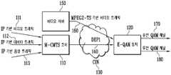
도 1은 케이블 네트워크의 헤드엔드 구조를 개념적으로 도시한 블록도이다.1 is a block diagram conceptually illustrating a headend structure of a cable network.
도 1을 참조하면, M-CMTS 코어(110)는 IP 기반 비디오 트래픽(111), IP 기반 데이터 트래픽(112) 및 IP 기반 음성 트래픽(113)을 수신하고, 상기 트래픽들을 DOCSIS MAC 프레이밍하여 E-QAM 장치(120)에게 전송한다. M-CMTS 코어(110) 및 E-QAM 장치(120)는 일반적으로 기가급 이더넷으로 구성되는 CIN(130, Converged Interconnect Network)을 통해 연결된다.Referring to FIG. 1, the M-
CIN(130)에 있어서, M-CMTS 코어(110) 및 E-QAM 장치(120)는 상호 간의 통신을 위해 IETF(Internet Engineering Task Force) 표준화 단체에서 제정한 계층-2 터널링 프로토콜 버전 3(Layer 2 Tunneling Protocol version 3, 이하 L2TPv3이라 칭함) 방식에 기반한 하향 외부 PHY 인터페이스(140, Downstream External PHY Interface, 이하 DEPI라 칭함) 프로토콜을 사용한다.In the
E-QAM 장치(120)는 방송 서비스 및 비디오 서비스를 위해 CIN(130)통하여 비 디오 서버(150)와 연결될 수 있다. 비디오 서버(150)는 일반적으로 IETF의 UDP 프로토콜을 이용하여 MPEG2-TS 기반 비디오 트래픽(160)을 E-QAM 장치(120)에게 전송한다.The E-QAM
E-QAM 장치(120)는 M-CMTS 코어(110) 및 비디오 서버(150)로부터 트래픽을 수신하여, 수신한 트래픽을 다양한 트래픽 조합으로 다중화하여 일정한 전송률을 갖는 단일 유선 QAM 채널(170)로 전송할 수 있다. 유선 QAM 채널(170)은 액세스 망 포설의 용이함 등을 장점으로 갖는 무선 QAM 채널(180)로 대체될 수 있으며, 무선 QAM 채널(180)을 사용하는 경우 E-QAM 장치(120)는 유선 QAM 채널(170)과 같은 일정한 전송률을 유지할 수 없다.The E-QAM
M-CMTS 코어(110) 및 비디오 서버(150)를 포함하는 각각의 트래픽 소스(Traffic Source)들로부터 E-QAM 장치(120)로 트래픽을 전송하는데 사용되는 프로토콜(예를 들어, DEPI 프로토콜)은 트래픽 다중화 과정에서 사용되는 수신 버퍼의 오버플로우(overflow)를 예방하기 위해 개방형 흐름 제어(Open-Loop Flow Control)를 사용한다. 다시 말해, 각각의 트래픽 소스는 유선 QAM 채널(170)의 일정한 출력 전송률 및 E-QAM 장치(120)의 트래픽 다중화 조합 설정에 기반하여 E-QAM 장치로 출력하는 트래픽 전송률을 고정적으로 설정한다.The protocol (e.g., DEPI protocol) used to transmit traffic from each traffic source including M-
종래의 케이블 네트워크에서 M-CMTS 코어 및 E-QAM 장치 간에 사용되는 DEPI 프로토콜의 구성 및 세션 연결 과정을 이하 도 2 내지 도 5c를 통해 설명하기로 한다.The configuration and session connection process of the DEPI protocol used between the M-CMTS core and the E-QAM device in the conventional cable network will be described below with reference to FIGS. 2 to 5C.
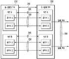
도 2는 DEPI 프로토콜의 구성을 개념적으로 도시한 블록도이다.2 is a block diagram conceptually illustrating a configuration of a DEPI protocol.
도 2를 참조하면, DEPI 프로토콜에 따르는 M-CMTS 코어(210) 및 E-QAM 장치(220)는 제어 메시지 교환에 사용되는 제어 연결(230, Control Connection) 및 데이터를 전송하기 위한 세션(240, Session)을 형성한다. 이때, 하나의 M-CMTS 코어(210)는 제어 연결(230)을 통해 하나의 E-QAM 장치(220)와 일대 일로 맵핑되어 제어 메시지들을 송수신할 수 있다.Referring to FIG. 2, the M-
제어 연결이 설정되면, 하나의 M-CMTS 코어(210)는 세션(240)을 통해 하나의 QAM 채널(260)과 일대 일로 맵핑되어 데이터를 송수신할 수 있다. 다시 말해, M-CMTS 코어(210)는 E-QAM 장치(220)와 최초에 제어 연결(230)을 설정하는 소정의 절차를 통하여 하나의 제어 연결(230)을 설정하게 되고, 상기 제어 연결(240)을 통하여 E-QAM 장치(220)내의 각 QAM 채널(260)과 세션(240)을 설정하게 된다.When the control connection is established, one M-
세션(240)을 설정하는 과정에 있어서, 한 개 이상의 데이터 전송 경로가 설정되는데 이를 데이터 플로우(250, Data Flow)라 한다. 세션은 데이터 플로우(250)상으로 전송되는 데이터 형식에 따라 D-MPT(DOCSIS MPEG Transport) 세션과 PSP(Packet Stream Protocol) 세션으로 분류될 수 있다.In the process of setting up the
D-MPT 세션은 하나의 데이터 플로우만 설정가능하며, M-CMTS 코어(210)에서 MPEG2-TS를 생성하여 전송하는 세션이다. 반면에, PSP 세션은 데이터의 우선순위에 따라 하나 이상의 데이터 플로우들을 설정할 수 있으며, E-QAM 장치(220)에서 MPEG2-TS를 생성하는 세션이다.Only one data flow can be set in the D-MPT session, and the M-
E-QAM 장치(220)는 버퍼를 이용하여 유입되는 트래픽들을 다중화하고 전송할 수 있다. E-QAM 장치(220)는 데이터 플로우 별로 고정 크기의 버퍼를 운용할 수도 있고, 또는 버퍼 풀(Pool)을 운용하여 각각의 데이터 플로우에 대하여 동적으로 버퍼를 할당할 수도 있다.The
도 3은 DEPI 프로토콜에서 사용되는 제어 패킷(Control Packet)의 형식을 도시한 도면이다.3 is a diagram illustrating a format of a control packet used in the DEPI protocol.
도 3을 참조하면, 제어 패킷은 14 바이트의 이더넷 802.3 헤더(310), 4 바이트의 이더넷 802.1Q 선택적 헤더(320), 20 바이트의 IPv4 헤더(330), 8 바이트의 UDP 헤더(340), 16 바이트의 L2TPv3 제어 헤더(350), 가변 길이의 AVP 리스트(360, List of AVP: Attribute Value Pair) 및 4 바이트의 CRC(370)를 포함하는 L2TPv3 프로토콜의 제어 패킷 형식을 사용하며, 이는 DEPI가 L2TPv3 프로토콜을 기본적으로 따르고 있기 때문이다. Referring to FIG. 3, the control packet includes 14 bytes of the Ethernet 802.3
제어 패킷은 UDP 헤더를 포함하는 제어패킷과 UDP 헤더를 포함하지 않는 제어패킷으로 분류된다. UDP 헤더를 포함하는 제어 패킷은 세션을 UDP 헤더로 구분하기 때문에 8 바이트의 UDP 헤더(340)는 포함하지만 L2TPv3 제어 헤더(350) 중 4 바이트의 세션 ID(351)는 포함하지 않는다. 반면 UDP 헤더를 포함하지 않는 제어 패킷은 세션을 구분하기 위해서 세션 ID를 이용하기 때문에 8 바이트의 UDP 헤더(340)를 포함하지 않지만 L2TPv3 제어 헤더(350) 중 4 바이트의 세션 ID(351)을 포함한다.The control packet is classified into a control packet including a UDP header and a control packet not including a UDP header. The control packet including the UDP header includes an 8-
L2TPv3 제어 헤더(350)는 패킷 형태를 나타내는 1 비트의 타입 필드(352, 제어 메시지는 1로 설정), 길이 필드의 유효함을 나타내는 1 비트의 길이 지시 필드(353), 순서 번호 필드의 유효함을 나타내는 1 비트의 순서 지시 필드(354), 프 로토콜 버전을 나타내는 3 비트의 버전 필드(355), 길이를 나타내는 2 바이트의 길이 필드(356), 제어 연결을 구분하기 위한 4 바이트의 제어 연결 ID 필드(357), 2 바이트의 전송 순서 번호 필드(358, Sending Sequencing Number: Ns) 및 2 바이트의 수신 순서 번호 필드(359, Received Sequencing Number: Nr)를 포함한다.The
AVP 리스트(360)는 제어 연결을 설정하는데 사용되는 하나 이상의 AVP(Attribute Value Pair)로 구성된다. 하나의 AVP는 AVP의 필요함을 나타내는 1 비트의 의부 필드(361, Mandatory bit: M), AVP의 암호화를 나타내는 1 비트의 히든 필드(362, Hidden bit: H), AVP의 길이를 나타내는 10 비트의 길이 필드(364), 각 벤더를 구분하기 위한 2 바이트의 벤더 ID 필드(365, DEPI에서는 4491값을 이용), AVP의 종류를 나타내는 2 바이트의 속성 타입 필드(366) 및 AVP의 값을 나타내는 가변 길이의 속성 값 필드(367)를 포함한다.
도 4는 DEPI 프로토콜에서 제어 패킷을 이용하여 세션을 설정하는 절차를 도시한 흐름도이다.4 is a flowchart illustrating a procedure for establishing a session using a control packet in the DEPI protocol.
도 4를 참조하면, M-CMTS 코어(401)는 E-QAM 장치(402)에게 메시지 타입, 시리얼 번호 등의 AVP를 포함하는 인커밍-콜-요구 메시지(410, Incoming-Call-Request: ICRQ)를 전송하여 세션 설정을 요구한다. 상기 인커밍-콜-요구 메시지(410)를 수신한 E-QAM 장치(402)는 메시지 타입, 지역 세션 ID 등의 AVP를 포함하는 인커밍-콜-응답 메시지(420, Incoming-Call-Reply: ICRP)를 M-CMTS 코어(401)에게 전송하여 요구에 대한 응답을 한다. 상기 응답을 수신한 M-CMTS 코어(401)는 연결 완료를 통보하는 인커밍-콜-연결 메시지(430, Incoming-Call-Connected: ICCN)를 다시 E-QAM 장치(402)에게 전송함으로써 세션 설정을 완료한다.Referring to FIG. 4, the M-
도 5a, 도 5b 및 도 5c는 DEPI 프로토콜에서 세션 설정에 사용되는 AVP들을 도시한 도면이다.5A, 5B, and 5C illustrate AVPs used for session establishment in a DEPI protocol.
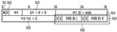
도 5a는 DEPI 자원 할당 요구(Resource Allocation Request) AVP(510)의 형식을 도시한 것이다. 도 5a를 참조하면, AVP의 기본 필드인 M 필드(511)는 ICRQ 메시지에 반드시 포함되어야 하기 때문에 1로 설정되고, 길이 필드(513)는 6+N으로 설정된다. 또한, 벤더 ID 필드(514)는 4491로 설정되고, 속성 타입 필드(515)는 2로 설정되고, 마지막으로 속성 값 필드(516)는 트래픽 우선순위를 나타내는 PHB ID 값으로 설정된다.5A illustrates the format of a DEPI Resource
도 5b는 DEPI 자원 할당 응답(Resource Allocation Reply) AVP(520)의 형식을 도시한 것이다. 도 5b를 참조하면, AVP의 기본 필드인 M 필드(521)는 ICRP 메시지에 반드시 포함되어야 하기 때문에 1로 설정되고, 길이 필드(523)는 8+4*N으로 설정된다. 또한 벤더 ID 필드(524)는 4491로 설정되고, 속성 타입 필드(525)는 2로 설정되고, 마지막으로 속성 값 필드(526)는 DEPI 자원 할당 요구 AVP(510)의 각 PHB ID에 대한 플로우 ID, UDP 목적지 포트의 값으로 설정된다.5B shows the format of a DEPI Resource
도 5c는 EQAM 능력(Capabilities) AVP(530)의 형식을 도시한 것이다. 도 5c를 참조하면, AVP의 기본 필드인 M 필드(521)는 ICRQ 메시지에 반드시 포함되어야 하기 때문에 1로 설정되고, 길이 필드(523)는 8로 설정된다. 벤더 ID 필드(534)는 4491로 설정되고, 속성 타입 필드(535)는 6으로 설정되고, 마지막으로 속성 값 필드(536)는 EQAM의 기능에 대한 비트 마스크 값을 가지는 EQAM 능력 필드로 설정된 다. 비트 0은 패킷 전송 지연을 보고하는 패킷을 생성에 대한 기능을 지시하는 비트 값이다. 비트 1부터 비트 15까지는 사용하지 않는 예약된 비트 값이다.5C illustrates the format of the
그러나, DEPI 프로토콜과 같은 프로토콜을 사용하는 종래의 개방형 흐름 제어 방식은 트래픽의 다중화를 제한하고, 특히 M-CMTS 코어 및 비디오 서버로부터의 가변비트율(Variable Bit Rate) 비디오 트래픽을 다른 트래픽과 다중화하는데 있어서 비효율적이다. 또한 E-QAM 장치(120)가 무선 QAM 채널을 사용하여 트래픽을 전송하는 경우, 무선 QAM 채널의 가변 전송률로 인해 오버플로우 또는 언더플로우(underflow)가 자주 발생할 수 있으므로, 능동적인 트래픽 흐름 제어가 필요하다.However, conventional open flow control schemes using protocols such as the DEPI protocol limit the multiplexing of traffic, especially in multiplexing variable bit rate video traffic from M-CMTS cores and video servers with other traffic. Inefficient In addition, when the
따라서, 본 발명에서 이루고자 하는 기술적 과제는 E-QAM 장치의 데이터 플로우에 대한 버퍼의 상태를 트래픽 소스에게 보고함으로써 능동적인 트래픽 전송률 조정이 가능한 폐쇄형 흐름 제어(Close-Loop Flow Control) 방식의 하향 트래픽 흐름 제어 방법을 제공하는 것이다.Therefore, the technical problem to be achieved in the present invention is to report the status of the buffer for the data flow of the E-QAM device to the traffic source, the traffic traffic of the closed-loop control (Close-Loop Flow Control) method that can actively adjust the traffic rate It is to provide a flow control method.
상술한 문제점을 해결하기 위한 본 발명의 일 측면은 변조 장치와 세션을 설정하는 단계; 상기 세션을 통해 상기 변조 장치에게 트래픽을 전송하는 단계; 및 상기 트래픽을 전송하는 도중 상기 변조 장치로부터 수신 버퍼의 상태를 보고하는 버퍼 상태 보고 메시지를 수신하는 단계를 통하여 케이블 네트워크 헤드엔드에서 트래픽 소스가 변조 장치에게 전송하는 하향 트래픽의 흐름을 제어하는 케이블 네트워크 헤드엔드의 하향 트래픽 흐름 제어 방법을 제공한다. 바람직하게는, 상기 세션을 설정하는 단계는 상기 트래픽 소스가 버퍼 상태 보고 기준을 포함하는 보고 기준 메시지를 생성하는 단계; 및 상기 트래픽 소스가 상기 생성된 보고 기준 메시지를 상기 변조 장치에게 전송하는 단계를 포함할 수 있다.One aspect of the present invention for solving the above problems is a step of establishing a session with the modulation device; Sending traffic to the modulation device over the session; And a cable network controlling a flow of downlink traffic transmitted from a traffic source to a modulation device at a cable network headend through a step of receiving a buffer status report message reporting a status of a reception buffer from the modulation device while transmitting the traffic. Provides a method for controlling downlink traffic flow of a headend. Advantageously, establishing the session comprises: generating, by the traffic source, a reporting criteria message comprising buffer status reporting criteria; And transmitting, by the traffic source, the generated reporting reference message to the modulation device.
본 발명의 다른 측면은 상기 변조 장치에게 버퍼 상태 보고 요청 메시지를 전송하는 단계; 및 상기 변조 장치로부터 상기 버퍼 상태 보고 요청 메시지에 응답하여 생성된 버퍼 상태 보고 메시지를 수신하는 단계를 통하여 케이블 네트워크 헤드엔드에서 트래픽 소스가 변조 장치에게 전송하는 하향 트래픽의 흐름을 제어하는 케이블 네트워크 헤드엔드의 하향 트래픽 흐름 제어 방법을 제공한다. 바람직하게는, 상기 버퍼 상태 보고 메시지를 수신하는 단계 이후에 상기 트래픽 소스가 버퍼 상태 보고 기준을 포함하는 버퍼 상태 보고 응답 메시지를 생성하는 단계; 및 상기 트래픽 소스가 상기 버퍼 상태 보고 응답 메시지를 상기 변조 장치에게 전송하는 단계를 더 포함할 수 있다.Another aspect of the present invention includes the steps of sending a buffer status report request message to the modulation device; And receiving a buffer status report message generated in response to the buffer status report request message from the modulation device to control the flow of downlink traffic transmitted by the traffic source to the modulation device in the cable network headend. It provides a downlink traffic flow control method. Advantageously, after receiving the buffer status report message, the traffic source generates a buffer status report response message that includes buffer status report criteria; And sending, by the traffic source, the buffer status report response message to the modulation device.
도 6a 및 도 6b는 본 발명의 일 실시예에 따른 버퍼 상태 보고 기준에 대한 추가 AVP 형식을 도시한 도면이다.6A and 6B illustrate additional AVP formats for buffer status reporting criteria according to an embodiment of the present invention.
도 6a는 해당 세션의 모든 데이터 플로우에 대한 버퍼 상태를 보고하는 기준을 표시하는 DEPI 버퍼 상태 보고 기준(DEPI Buffer Status Reporting Criteria) AVP(610)의 형식을 도시한다.FIG. 6A illustrates the format of the DEPI Buffer Status
도 6a를 참조하면, DEPI 버퍼 상태 보고 기준 AVP(610)는 1로 설정된 M 필드(611), 14로 설정된 길이 필드(613), 4491로 설정된 벤더 ID 필드(614), 21로 설정된 속성 타입 필드(615)를 포함한다. 또한, 속성 값 필드(616)는 세션 내의 모든 데이터 플로우들에 대하여 버퍼 상태를 보고하는 세 가지 기준 값을 포함할 수 있는다.Referring to FIG. 6A, the DEPI buffer status
첫 번째 기준 값으로써, 1 내지 100 퍼센트의 범위에서 설정되는 8 비트의 버퍼 채워짐 임계값(Buffer Occupancy Threshold)이 있다. E-QAM 장치는 특정 섹션의 임의의 버퍼의 채워짐 정도가 상기 버퍼 채워짐 기준값에 도달하면 세션의 모든 데이터 플로우에 대한 버퍼 상태를 M-CMTS 코어에게 보고한다.As a first reference value, there is an 8-bit Buffer Occupancy Threshold set in the range of 1 to 100 percent. The E-QAM device reports to the M-CMTS core the buffer status for all data flows in the session when the degree of filling of any buffer in a particular section reaches the buffer filling threshold.
두 번째 기준 값으로써, 1 내지 65535 msec의 범위에서 설정되는 16비트의 버퍼 상태 보고 타이머(Buffer Status Reporting Timer)가 있다. E-QAM 장치는 세션 연결 후, 최초 트래픽 수신시에 상기 버퍼 상태 보고 타이머 값으로 타이머를 구동한다. 이후, E-QAM 장치는 타이머가 만료될 때마다 세션의 모든 데이버 플로우에 대한 버퍼 상태를 M-CMTS 코어에게 보고하고 상기 타이머를 다시 구동한다.As a second reference value, there is a 16-bit buffer status reporting timer set in the range of 1 to 65535 msec. After the session connection, the E-QAM device drives a timer with the buffer status report timer value upon initial traffic reception. Thereafter, whenever the timer expires, the E-QAM device reports the buffer status for all data flows in the session to the M-CMTS core and drives the timer again.
세 번째 기준 값으로써, 16 비트의 수신 MPEG-TS 패킷 또는 세그먼트 수(Number of Received MPEG-TS Packets or Segments)가 있다. E-QAM 장치는 동일 세션에 속한 모든 데이터 플로우들의 수신 MPEG-TS 패킷 또는 세그먼트 수가 상기 수신 MPEG-TS 패킷 또는 세그먼트 수에 도달하면 해당 세션의 모든 데이터 플로우에 대한 버퍼 상태를 M-CMTS 코어에게 보고하고 상기 수신 패킷 또는 세그먼트 수를 초기화한다.As a third reference value, there are 16 bits of received MPEG-TS packets or segments. The E-QAM device reports to the M-CMTS core the buffer status for all data flows of the session when the number of received MPEG-TS packets or segments of all data flows belonging to the same session reaches the number of received MPEG-TS packets or segments. And initialize the number of received packets or segments.
도 6b는 세션의 모든 데이터 플로우에 대한 버퍼 상태를 보고하는 DEPI 버퍼 상태 보고(DEPI Buffer Status Reporting) AVP의 형식을 도시한다.6B illustrates the format of a DEPI Buffer Status Reporting AVP that reports buffer status for all data flows in a session.
도 6b를 참조하면, DEPI 버퍼 상태 보고 AVP(620)는 1로 설정된 M 필드(621), 6+6*N로 설정된 길이 필드 (623), 4491로 설정된 벤더 ID 필드(624), 22로 설정된 속성 타입 필드(625)를 포함한다. 또한, 속성 값 필드(626)는 세션 내의 데이터 플로우를 식별하기 위한 3 비트의 플로우 ID 값, 상기 플로우 ID 값을 갖는 데이터 플로우에 대한 버퍼의 여유 공간 크기를 나타내는 24 비트의 여유 버퍼 크기 필드 및 상기 버퍼에 저장된 수신 DEPI 페이로드의 최대 시퀀스 번호(Maximum Sequence Number of Received DEPI Payload) 필드를 포함한다.Referring to FIG. 6B, the DEPI buffer
상기 추가 AVP를 통해 M-CMTS 코어는 버퍼 상태 보고 기준을 설정하여 E-QAM 장치에게 전달하고, E-QAM 장치는 상기 기준에 기반하여 버퍼 상태를 보고하거나 일정 주기 마다 버퍼 상태를 보고할 수 있다.Through the additional AVP, the M-CMTS core sets a buffer status reporting criterion and delivers it to the E-QAM device, and the E-QAM device may report the buffer status or report the buffer status at regular intervals based on the criterion. .
도 7은 본 발명의 일 실시예에 따른 추가 AVP를 포함하는 제어 패킷을 이용하여 세션을 설정하는 절차를 도시한 흐름도이다.7 is a flowchart illustrating a procedure for establishing a session using a control packet including an additional AVP according to an embodiment of the present invention.
도 7을 참조하면, 세션을 설정하기 위해 최초에 M-CMTS 코어(701)는 E-QAM 장치(702)에게 ICRQ 메시지(710)를 전송하여 세션 설정을 요구한다. 이때 ICRQ 메시지(710)는 복수의 6 비트 PHB 값을 포함하는 DEPI 자원 할당 요구 AVP를 포함한다.Referring to FIG. 7, in order to establish a session, the M-
ICRQ 메시지(710)를 수신한 E-QAM 장치는 ICRQ 메시지(710)내의 DEPI 자원 할당 요구 AVP에 대한 응답으로 DEPI 자원 할당 응답 AVP를 포함한 ICRP 메시 지(720)를 전송한다. 이때 DEPI 자원 할당 응답 AVP는 M-CMTS 코어(701)에서 요구한 모든 PHB ID에 대해서 할당한 플로우 ID 값과 UDP 포트 번호를 포함하고 있다.Upon receiving the
ICRP 메시지(720)를 수신한 M-CMTS 코어(701)는 ICRP 메시지(720)내의 DEPI 자원 할당 응답 AVP 내의 값으로 설정된 플로우 수를 인지할 수 있다. M-CMTS 코어(701)는 플로우 수에 기반하여 버퍼 상태 보고 기준 AVP를 생성하고, 상기 버퍼 상태 보고 기준 AVP를 포함한 ICCN 메시지(730)를 전송함으로써 세션 설정을 완료한다.The M-
ICCN 메시지(730)를 수신한 E-QAM 장치(702)는 ICCN 메시지(730)에 포함된 버퍼 상태 보고 기준 AVP에 따라 버퍼 보고 기준을 설정하고 이후 설정된 기준에 따라 버퍼 상태를 보고한다. 이와 같은 세션 설정 절차를 통해, M-CMTS 코어(701)는 버퍼 상태 보고 기준을 E-QAM 장치(702)에게 전달할 수 있다. Upon receiving the
본 발명의 일 실시예에 따른 버퍼 상태 보고 방법으로서 M-CMTS 코어의 버퍼 상태 보고 요청에 따라 보고하는 방법 및 M-CMTS 코어에서 E-QAM 장치로 전송되는 데이터 패킷의 헤더 내 비트의 설정에 따라 보고 방법이 있다. 상기 추가적인 보고 방법에 대해서는 표 1 및 도 8 내지 도 9c를 통하여 후술하기로 한다.According to a buffer status reporting method according to an embodiment of the present invention, a method for reporting according to a buffer status report request of an M-CMTS core and a setting of bits in a header of a data packet transmitted from an M-CMTS core to an E-QAM device are provided. There is a way to report. The additional reporting method will be described later with reference to Table 1 and FIGS. 8 to 9C.
표 1은 본 발명의 일 실시예에 따라 M-CMTS 코어의 요청에 응답하여 버퍼 상태를 보고하는 방법에 관련한 추가 메시지를 나타낸 표이다.Table 1 is a table showing additional messages related to a method of reporting a buffer status in response to a request of an M-CMTS core according to an embodiment of the present invention.
표 1을 참조하면, BSRQ 메시지는 버퍼 상태 보고를 요청하기 위해 M-CMTS 코어에서 E-QAM 장치로 전송되는 메시지이고 BSRP 메시지는 버퍼 상태를 보고하기 위해 E-QAM 장치에서 M-CMTS 코어로 전송되는 메시지이다. BSRN 메시지는 버퍼 상태 보고 메시지에 대한 응답 메시지로 M-CMTS 코어에서 E-QAM 장치로 전송되는 메시지이다.Referring to Table 1, the BSRQ message is sent from the M-CMTS core to the E-QAM device to request buffer status reporting and the BSRP message is sent from the E-QAM device to the M-CMTS core to report buffer status. Message. The BSRN message is a message sent from the M-CMTS core to the E-QAM device in response to the buffer status report message.
도 8는 본 발명의 일 실시예에 따라 버퍼 상태 보고를 요청하고 응답하는 절차를 도시한 흐름도이다.8 is a flowchart illustrating a procedure for requesting and responding to a buffer status report according to an embodiment of the present invention.
도 8을 참조하면, M-CMTS 코어(801)는 E-QAM 장치(802)에게 BSRQ 메시지(810)를 전송하여 설정된 세션의 모든 데이터 플로우들에 대한 버퍼 상태 보고를 요청한다. 이때 BSRQ 메시지(810)는 BSRQ 메시지(810)임을 나타내는 메시지 타입 AVP, 해당 메시지에 대한 시리얼 번호 AVP, M-CMTS 코어에서 사용하는 세션 ID를 나타내는 지역 세션 ID AVP 및 E-QAM 장치에서 사용하는 세션 ID를 나타내는 원격 세션 ID AVP를 포함하고 있다.Referring to FIG. 8, the M-
BSRQ 메시지(810)를 수신한 E-QAM 장치(802)는 BSRQ 메시지(810)내의 원격 세션 ID AVP에 기반하여 해당 세션의 데이버 플로우별 버퍼 상태를 기록한 버퍼 상태 보고 AVP를 포함한 BSRP 메시지(820)를 생성하여 M-CMTS 코어(801)에게 전송한다.Receiving the
BSRP 메시지(820)를 수신한 M-CMTS 코어(801)는 BSRP 메시지(820)내의 버퍼 상태 보고 AVP를 이용하여 각 데이터 플로우별 버퍼 상태를 인지하고, 이에 기반하여 E-QAM 장치(802)에 전송하는 트래픽의 흐름을 제어한다.Receiving the
M-CMTS 코어(801)는 BSRP 메시지(820)에 대한 응답으로 BSRN 메시지(830)를 E-QAM 장치(802) 전송함으로써 버퍼 상태 보고 절차를 완료한다.The M-
여기서, BSRN 메시지(830)는 버퍼 상태 보고에 대한 기준을 다시 설정하는 버퍼 상태 보고 기준 AVP를 포함할 수 있다. 따라서, E-QAM 장치(802)는 수신한 BSRN 메시지(830)에 버퍼 상태 보고 기준 AVP가 포함되어 있는 경우, 각 데이터 플로우에 대한 버퍼 상태 보고 기준을 재설정하여 이후 설정된 기준에 따라 버퍼 상태를 보고한다.In this case, the
일 실시예에서, E-QAM 장치(802)는 BSRQ 메시지(810)에 의한 요청뿐만 아니라 ICCN 메시지(730) 또는 BSRN 메시지(830)를 통해 설정된 버퍼 상태 보고 기준에 따라 상기 BSRP 메시지(820)를 생성하여 M-CMTS 코어(801)로 전송할 수 있다. M-CMTS 코어(801)는 전술한 바와 같이 그에 대한 응답으로 새로운 버퍼 상태 보고 기준을 포함하는 BSRN 메시지(830)를 생성하여 전송할 수 있다.In one embodiment, the
도 9a, 도 9b 및 도 9c는 본 발명의 일 실시예에 따른 DEPI 프로토콜을 통해 전송되는 데이터 패킷의 형식을 도시한 도면이다.9A, 9B, and 9C are diagrams illustrating a format of a data packet transmitted through a DEPI protocol according to an embodiment of the present invention.
도 9a를 참조하면, 데이터 패킷 형식은 14 바이트의 이더넷 802.3 헤더(910), 4 바이트의 이더넷 802.1Q 선택적 헤더(920), 20 바이트의 IPv4 헤더(930), 8 바이트의 UDP 헤더(940), 4 또는 8 바이트의 L2TPv3 데이터 헤더(950), 4 또는 4+2*N 바이트의 L2TPv3 서브-계층 헤더(960) 및 4 바이트의 CRC(980)를 포함한다.Referring to FIG. 9A, the data packet format includes a 14 byte Ethernet 802.3
데이터 패킷은 UDP 헤더를 포함하는 데이터 패킷과 UDP 헤더를 포함하지 않는 데이터 패킷으로 분류된다. UDP 헤더를 포함하는 제어 패킷은 세션을 UDP 헤더로 구분하기 때문에 8 바이트의 UDP 헤더(940)를 포함하지만 L2TPv3 데이터 헤더(950) 중 4 바이트의 세션 ID를 포함하지 않는다. 반면, UDP 헤더를 포함하지 않는 데이터 패킷은 세션을 구분하기 때문에 8 바이트의 UDP 헤더(940)를 포함하지 않지만 L2TPv3 데이터 헤더(950) 중 4 바이트의 세션 ID를 포함한다.Data packets are classified into data packets including UDP headers and data packets not including UDP headers. The control packet including the UDP header includes 8 bytes of
데이터 패킷 내의 L2TPv3 서브-계층 헤더(960)는 데이터 패킷의 종류에 따라 다르게 구성되는데, 도 9b 및 도 9c는 전술한 각 D-MPT 세션 및 PSP 세션에서 사용되는 데이터 패킷의 L2TPv3 서브-계층 헤더 형식(960)을 도시한 것이다. 도 9b 및 도 9c를 참조하면, 플로우 ID 필드(964) 다음에 위치하는 사용하지 않는 1 비트(965)를 보고(Reporting: R) 비트 마스크 필드(965)로 사용하여 E-QAM 장치가 데이터 플로우의 버퍼 상태를 보고 하도록 할 수 있다. 즉, E-QAM 장치가 데이터 패킷을 수신할 때, 데이터 패킷의 L2TPv3 서브-계층 헤더(960) 내의 R 필드(965)가 1로 설정되어 있는 경우, E-QAM 장치는 해당 데이터 패킷이 속한 데이터 플로우에 대한 버퍼 상태를 보고할 수 있다.The
이상에서 설명한 본 발명은 전술한 실시예 및 첨부된 도면에 의해 한정되는 것은 아니고, 본 발명의 기술적 사상을 벗어나지 않는 범위 내에서 여러 가지 치환, 변형 및 변경이 가능하다는 것은 본 발명이 속하는 기술분야에서 통상의 지식을 가진 자에게 있어 명백할 것이다.The present invention described above is not limited to the above-described embodiments and the accompanying drawings, and various substitutions, modifications, and changes are possible in the art without departing from the technical spirit of the present invention. It will be clear to those of ordinary knowledge.
본 발명은 E-QAM 장치의 버퍼 상태 정보를 트래픽 소스에게 보고함으로써, 트래픽 소스가 E-QAM 장치로 전송하는 트래픽 전송률을 제어할 수 있도록 하고, 나아가 수신 버퍼의 오버플로우/언더플로우, 패킷 손실 및 채널 사용율 저하를 예방할 수 있다.The present invention reports the buffer status information of the E-QAM device to the traffic source, thereby controlling the traffic rate transmitted by the traffic source to the E-QAM device, furthermore, overflow / underflow of the receiving buffer, packet loss and The decrease in channel utilization can be prevented.
또한, 본 발명은 일정한 기준에 따라 E-QAM 장치의 버퍼 상태 정보를 트래픽 소스에게 보고하는 방법을 제공함으로써, 트래픽 흐름 제어 정책에 따라 보고 기준을 선택할 수 있는 유연성을 제공한다..In addition, the present invention provides a method of reporting buffer status information of an E-QAM device to a traffic source according to a predetermined criterion, thereby providing flexibility in selecting a reporting criterion according to a traffic flow control policy.
또한, 본 발명은 트래픽 소스가 요청 메시지 또는 데이터 패킷의 필드를 사용하여 버퍼 상태의 보고를 요청할 수 있는 방법을 제공함으로써, 버퍼의 오버플로우/언더플로우 등의 상황에 신속하게 대처할 수 있다.In addition, the present invention provides a method by which a traffic source can request a report of a buffer status using a field of a request message or a data packet, so that a situation such as overflow / underflow of a buffer can be quickly coped with.
Claims (22)
Translated fromKoreanPriority Applications (1)
| Application Number | Priority Date | Filing Date | Title |
|---|---|---|---|
| US11/947,519US20090016218A1 (en) | 2006-12-06 | 2007-11-29 | Method of controlling downstream traffic flow in cable network headend |
Applications Claiming Priority (2)
| Application Number | Priority Date | Filing Date | Title |
|---|---|---|---|
| KR1020060122890 | 2006-12-06 | ||
| KR20060122890 | 2006-12-06 |
Publications (2)
| Publication Number | Publication Date |
|---|---|
| KR20080052218A KR20080052218A (en) | 2008-06-11 |
| KR100872776B1true KR100872776B1 (en) | 2008-12-09 |
Family
ID=39807065
Family Applications (1)
| Application Number | Title | Priority Date | Filing Date |
|---|---|---|---|
| KR1020070053337AExpired - Fee RelatedKR100872776B1 (en) | 2006-12-06 | 2007-05-31 | Method for Controlling Downstream Traffic Flow in Cable Network Headend |
Country Status (2)
| Country | Link |
|---|---|
| US (1) | US20090016218A1 (en) |
| KR (1) | KR100872776B1 (en) |
Families Citing this family (10)
| Publication number | Priority date | Publication date | Assignee | Title |
|---|---|---|---|---|
| BRPI0709190A2 (en)* | 2006-03-29 | 2011-06-28 | Thomson Licensing | video via cable modem |
| US8655950B2 (en)* | 2008-08-06 | 2014-02-18 | International Business Machines Corporation | Contextual awareness in real time collaborative activity alerts |
| KR101182518B1 (en)* | 2009-01-22 | 2012-09-12 | 에스케이플래닛 주식회사 | Video streaming system and method |
| EP2756631B1 (en)* | 2011-09-16 | 2016-07-13 | Cisco Technology, Inc. | Generic control protocol |
| US9143808B2 (en)* | 2012-09-14 | 2015-09-22 | Cisco Technology, Inc. | Multi-channel MPEG between headend and fiber node |
| US9674098B2 (en)* | 2013-07-02 | 2017-06-06 | Intel Corporation | Credit flow control for ethernet |
| CA3172330A1 (en)* | 2020-03-20 | 2021-09-23 | Vasudevan JOTHILINGAM | Efficient remote phy dataplane management for a cable system |
| US11576117B1 (en)* | 2021-07-23 | 2023-02-07 | Charter Communications Operating, Llc | Methods and apparatus for cable network power management |
| US12003816B2 (en) | 2021-07-23 | 2024-06-04 | Charter Communications Operating, Llc | Methods and apparatus for dynamic cable network power management |
| US20230246899A1 (en)* | 2022-01-28 | 2023-08-03 | Arris Enterprises Llc | Priority based service to overcome qam overflow |
Citations (4)
| Publication number | Priority date | Publication date | Assignee | Title |
|---|---|---|---|---|
| KR20030037803A (en)* | 2001-11-06 | 2003-05-16 | 엘지전자 주식회사 | Message Exchanging Method between Cable Modem and Cable Modem Termination System |
| JP2004282210A (en) | 2003-03-13 | 2004-10-07 | Matsushita Electric Ind Co Ltd | Two-way cable TV receiver |
| US20050265376A1 (en) | 2004-05-25 | 2005-12-01 | Chapman John T | Wideband upstream protocol |
| KR20060003743A (en)* | 2004-07-07 | 2006-01-11 | 한국과학기술원 | TPC-friendly Streaming Method Using Decoder Buffer Controller |
Family Cites Families (6)
| Publication number | Priority date | Publication date | Assignee | Title |
|---|---|---|---|---|
| US7062568B1 (en)* | 2002-01-31 | 2006-06-13 | Forcelo Networks, Inc. | Point-to-point protocol flow control extension |
| KR100918435B1 (en)* | 2005-01-31 | 2009-09-24 | 삼성전자주식회사 | Data traffic control system and method in wireless communication system |
| US7823179B2 (en)* | 2005-04-18 | 2010-10-26 | Cisco Technology, Inc. | System and method for edge resource management |
| US7701951B2 (en)* | 2006-03-06 | 2010-04-20 | Cisco Technology, Inc. | Resource reservation and admission control for IP network |
| US20080095155A1 (en)* | 2006-10-24 | 2008-04-24 | Broadcom Corporation | Programmable communications system |
| US20080209489A1 (en)* | 2007-02-28 | 2008-08-28 | General Instrument Corporation | System and method for transmitting digital content using cable modem termination system (cmts) bypass architecture |
- 2007
- 2007-05-31KRKR1020070053337Apatent/KR100872776B1/ennot_activeExpired - Fee Related
- 2007-11-29USUS11/947,519patent/US20090016218A1/ennot_activeAbandoned
Patent Citations (4)
| Publication number | Priority date | Publication date | Assignee | Title |
|---|---|---|---|---|
| KR20030037803A (en)* | 2001-11-06 | 2003-05-16 | 엘지전자 주식회사 | Message Exchanging Method between Cable Modem and Cable Modem Termination System |
| JP2004282210A (en) | 2003-03-13 | 2004-10-07 | Matsushita Electric Ind Co Ltd | Two-way cable TV receiver |
| US20050265376A1 (en) | 2004-05-25 | 2005-12-01 | Chapman John T | Wideband upstream protocol |
| KR20060003743A (en)* | 2004-07-07 | 2006-01-11 | 한국과학기술원 | TPC-friendly Streaming Method Using Decoder Buffer Controller |
Also Published As
| Publication number | Publication date |
|---|---|
| KR20080052218A (en) | 2008-06-11 |
| US20090016218A1 (en) | 2009-01-15 |
Similar Documents
| Publication | Publication Date | Title |
|---|---|---|
| KR100872776B1 (en) | Method for Controlling Downstream Traffic Flow in Cable Network Headend | |
| CN101325547B (en) | Communication system, server, control apparatus and communication apparatus | |
| US6438123B1 (en) | Method and apparatus for supporting header suppression and multiple microflows in a network | |
| EP1965561B1 (en) | System and method for transmitting digital content using cable modem termination system (CMTS) bypass architecture | |
| US11558879B2 (en) | Handling network traffic via a fixed access | |
| US8179883B2 (en) | Apparatus, method and system for managing session encapsulation information within an internet protocol content bypass architecture | |
| JP4712014B2 (en) | Method for establishing wireless packet-based communication | |
| US7180904B2 (en) | Interface link layer device to build a distributed network | |
| US10171167B2 (en) | Multimedia network data processing system | |
| KR100837704B1 (en) | Data Transmission Method in Evolved MMTS Network System | |
| US8331269B2 (en) | Method and device for transmitting voice in wireless system | |
| EP1722523A1 (en) | Apparatus and method for reserving session resource in IPv4/IPv6 combination network | |
| US20090310596A1 (en) | Apparatus, method and system for managing bypass encapsulation of internet content within a bypass architecture | |
| US20070255793A1 (en) | Method for providing service between heterogeneous networks | |
| JP4703445B2 (en) | Host station and packet transmission method | |
| JP3519628B2 (en) | Relay device | |
| KR101515853B1 (en) | Gateway for data communication between MOST device and Ethernet device and method thereof | |
| KR100929083B1 (en) | How to provide heteromanganese services | |
| CN101170546B (en) | Data stream multiplexing method and data stream multiplexing system | |
| US9787801B2 (en) | Data transmission using a multihoming protocol as SCTP | |
| KR20090084602A (en) | Resource allocation request system and method in communication systems | |
| CN102905318A (en) | A method for allocating downlink bandwidth in a network, a network server and an AN |
Legal Events
| Date | Code | Title | Description |
|---|---|---|---|
| A201 | Request for examination | ||
| PA0109 | Patent application | St.27 status event code:A-0-1-A10-A12-nap-PA0109 | |
| PA0201 | Request for examination | St.27 status event code:A-1-2-D10-D11-exm-PA0201 | |
| D13-X000 | Search requested | St.27 status event code:A-1-2-D10-D13-srh-X000 | |
| D14-X000 | Search report completed | St.27 status event code:A-1-2-D10-D14-srh-X000 | |
| PG1501 | Laying open of application | St.27 status event code:A-1-1-Q10-Q12-nap-PG1501 | |
| E701 | Decision to grant or registration of patent right | ||
| PE0701 | Decision of registration | St.27 status event code:A-1-2-D10-D22-exm-PE0701 | |
| GRNT | Written decision to grant | ||
| PR0701 | Registration of establishment | St.27 status event code:A-2-4-F10-F11-exm-PR0701 | |
| PR1002 | Payment of registration fee | St.27 status event code:A-2-2-U10-U11-oth-PR1002 Fee payment year number:1 | |
| PG1601 | Publication of registration | St.27 status event code:A-4-4-Q10-Q13-nap-PG1601 | |
| PN2301 | Change of applicant | St.27 status event code:A-5-5-R10-R13-asn-PN2301 St.27 status event code:A-5-5-R10-R11-asn-PN2301 | |
| LAPS | Lapse due to unpaid annual fee | ||
| PC1903 | Unpaid annual fee | St.27 status event code:A-4-4-U10-U13-oth-PC1903 Not in force date:20111203 Payment event data comment text:Termination Category : DEFAULT_OF_REGISTRATION_FEE | |
| PC1903 | Unpaid annual fee | St.27 status event code:N-4-6-H10-H13-oth-PC1903 Ip right cessation event data comment text:Termination Category : DEFAULT_OF_REGISTRATION_FEE Not in force date:20111203 | |
| P22-X000 | Classification modified | St.27 status event code:A-4-4-P10-P22-nap-X000 | |
| PN2301 | Change of applicant | St.27 status event code:A-5-5-R10-R13-asn-PN2301 St.27 status event code:A-5-5-R10-R11-asn-PN2301 |